chapter 20 safety programming in the plcwevans/chap20_s.pdf · chapter 20 safety programming in the...
TRANSCRIPT
Ch 20 Safety Programming in the PLC 1
Chapter 20 Safety Programming in the PLC
Introduction
In engineering, redundancy is the duplication of critical components or functions of a system with the
intention of increasing reliability of the system, usually in the form of a backup or fail-safe, or to
improve actual system performance.
In many safety-critical systems, some parts of the control system may be triplicated, which is formally
termed triple modular redundancy (TMR). An error in one component may then be out-voted by the
other two. In a triply redundant system, the system has three sub components, all three of which must
fail before the system fails. Since each one rarely fails, and the sub components are expected to fail
independently, the probability of all three failing is calculated to be extraordinarily small; often
outweighed by other risk factors, such as human error. Redundancy sometimes produces less, instead
of greater reliability – it creates a more complex system which is prone to various issues, it may lead to
human neglect of duty, and may lead to higher production demands which by overstressing the system
may make it less safe
What is the difference between fault-tolerant designs and fail-safe designs? A fault-tolerant system is
designed to avoid total service failure caused by faults at any single point. Typically, a fault-tolerant
design applies redundancy or multiple safety barriers to enable the system to continue its intended
mission, possibly with reduced performance or increased response time in the event of some partial
failure, rather than to fail completely. An example of a fault-tolerant design is an aircraft with multiple
engines, so that it will keep flying even if one of the engines failed. A fail-safe system is designed to
fail in a safe and controlled manner, so that the failure will not endanger lives or properties, or at least
be no less safe than when it is operating correctly. For example, the brakes on a train are designed to
apply when the brake control system fails, to ensure safety by stopping the train. It must be noted that
a fail-safe system can also suffer 'wrong-side failure', as when, for example, a malfunctioning traffic
light shows green rather than flashing red or goes dark; but is to have a very low probability of this
occurring. In some cases, it may not be acceptable for one or even more failures to cause a system to
cease functioning. Unlike a fail-safe system that puts safety ahead of function or mission objective, a
'failoperational' system will continue to operate in spite of control systems failure. An example is the
thermostats in home air-conditioners.
PLC Systems use Fail-Safe Technology
Industrial automation is now considerably more flexible and open. Modern machines and systems also
stand out due to their significantly increased productivity. This is due in no small part to the fact that
relay technology has been replaced by the freely programmable controller and decentralization – at
least for demanding applications. In spite of this change in technology, very different products and
systems were often used until now for safety-oriented functions and standard tasks. If more complex
safety tasks are involved, however, the efficiency of an automation solution can be significantly
increased even if the safety technology consistently follows the trend toward intelligent PLCs.
A fail-safe PLC serves to control processes and immediately switches to a safer state or remains in the
current state if a fault occurs. It provides an integrated, efficient safety solution in systems with
increased safety requirements.
Programming is done in Siemens PLCs using the Step 7 languages LAD and FBD and TUV-certified
(German Technical Inspectorate) function blocks. The connection to the standard and safety-oriented
modules can be optionally made via PROFINET, the open Ethernet standard or via PROFIBUS.

Ch 20 Safety Programming in the PLC 2
The European guidelines apply today as those that reflect the highest safety standard and are accepted
far beyond the boundaries of Europe. In order to ensure the functional safety of a machine or system,
the safety-relevant parts of the protective and control systems behave in such a manner in the event of
a fault that the system remains in a safe state or is put into a safe state. To this end, special
requirements that are defined in standards are placed on the products. Corresponding product
certificates can document the compliance with these standards.
Any possible hazards to people and the environment cannot just be averted at the national level. They
must always comply with the regulations and rules of the location where the machine or system is
operated. Thus the free exchange of goods within the framework of global markets requires
internationally agreed codes of practice.
Safety requires protection against a variety of risks. These can be overcome as follows:
Design in accordance with risk-reducing design principles and risk assessment of the machine
Technical protection measures, if necessary by the use of safety-related controllers
Electrical safety
Functional safety involves the part of the safety of a machine or plant that depends on the correct
function of its control or protection equipment.
The analysis of risk follows a set procedure.
BGIA is now IFA
The name BGIA for years was associated with the German insurance industry responsible for setting
up rules for plant safety or workplace safety. The new name reflects a change in social accident
insurance.
The research institutes of the German Social Accident Insurance (DGUV) received new names and
abbreviations. As of 1 January 2010, the former BGIA in Sankt Augustin is now be named the
"Institute for Occupational Safety and Health of the German Social Accident Insurance", abbreviated
as "IFA". Why look to Germany? They have traditionally led the way in quantifying safety in the
workplace.
The Internet address of the institute changed accordingly:
As of 1 January 2010, the Institute for Occupational Safety and Health of the DGUV (IFA) is to be
found at www.dguv.de/ifa.
Application of the Machinery Directive 2006/42/EC [1] has been mandatory since 29 December 2009.
The directive lists products that are described as "logic units to ensure safety functions". These
products are stated in Annex IV of the Machinery Directive. This appendix lists products which owing
to their function are a source of particularly high hazards in the event of a fault. Accordingly, stricter
requirements apply to the conformity assessment method. The affected components and the possible
assessment methods are stated below.
1 What products are described as "logic units to ensure safety functions"? Products are affected by this
provision when:
a) they are safety components (see below) and are therefore governed by the Machinery Directive;
and

Ch 20 Safety Programming in the PLC 3
b) they are "logic units to ensure safety functions" in accordance with Annex IV, No. 21 (see
below).
Concerning a): safety component in accordance with the Machinery Directive Article 1 of the
Machinery Directive states its scope. The products considered here fall under c) safety components. In
Sub-point c), Article 2 contains the definition of a safety component:
c) “safety component” means a component
• which serves to fulfil a safety function
• which is independently placed on the market,
• the failure and/or malfunction of which endangers the safety of persons, and
• which is not necessary in order for the machinery to function, or for which normal
components may be substituted in order for the machinery to function.
If the above definition is applied for example to a safety PLC (Programmable Logic Controller), the
following conclusion is reached: a safety PLC
• serves to fulfil a safety function
• is placed independently on the market, i.e. it is not supplied solely fitted to a machine
• endangers the safety of persons in the event of its failure and/or malfunction
• is not necessary for the machinery to function when used solely for the implementation of
safety functions, or can be substituted by a conventional PLC for the purpose of the
functioning of the machine, if non safety related functions are also performed.
Under the provisions of the Machinery Directive, a safety PLC is therefore classified as a safety
component. As this example shows, the definition applies both to products which are employed solely
for safety functions and to products which at the same time fulfil both safety functions and machine
functions. An additional aid for determining whether a component is a safety component can be found
in Annex V of the Machinery Directive. This contains a non-exhaustive list of safety components.
Concerning b): logic units to ensure safety functions The background to the inclusion of these
components in Annex IV is the growing use of functional safety products in machine controls. The
Machinery Directive also lists the "logic units to ensure safety functions” in Annex V, but does not
define these components. Clarification is provided by the "Guide to application of the Machinery
Directive 2006/42/EG" [2]:
Ch 20 Safety Programming in the PLC 4
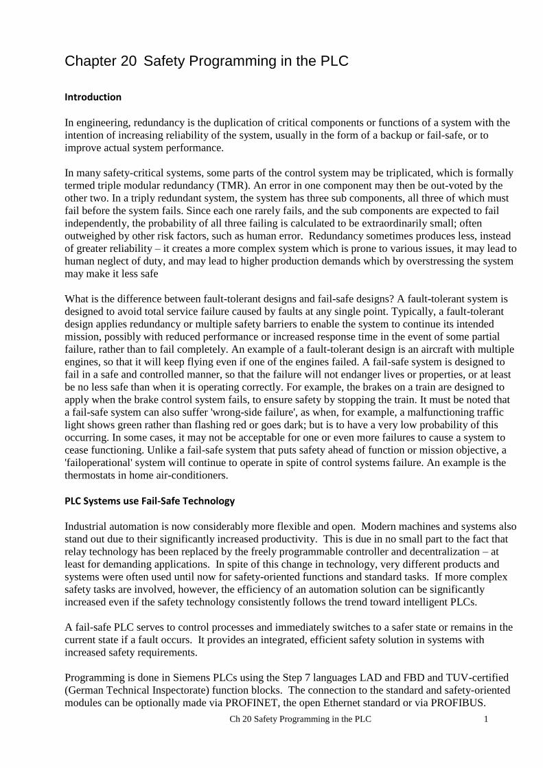
If these explanations are applied to products that are typically employed for the implementation of
safety functions on machines, the result is the list (not exhaustive) shown in Table 1 in which products
are classified according to whether they are logic units. This list, proposed by the IFA as early as 2009,
has since been adopted by the European Commission and published as "recommendations for use" for
mandatory application by the notified bodies [3]. Notified bodies are authorized to perform EC type
examinations.
This table is shown below:

Ch 20 Safety Programming in the PLC 5

Ch 20 Safety Programming in the PLC 6
Logic units to ensure safety functions
In accordance with Annex IV of the Machinery Directive
On 29 December 2009, application of the new Machinery Directive, 2006/42/EC, becomes mandatory.
One of the associated changes concerns "logic units to ensure safety functions". These are now
referred to in Annex IV of the directive. This product group is not precisely defined, however. Owing
to the reference to these products in Annex IV of the Machinery Directive, stricter requirements apply
to the conformity assessment procedure for application of the CE mark.
For the purpose of defining logic units to ensure safety functions, the IFA has made an article available
for download in which it classifies the components frequently employed in machine controls. The
products concerned include safety PLCs (programmable logic controllers), power drive systems with
integrated safety functions, safety switchgear, and any components for which the manufacturer states a
Category, Performance Level or Safety Integrity Level. The classification of a component as a "logic
unit to ensure safety functions" constitutes an estimation made by the IFA in liaison with other German
test bodies.
Ch 20 Safety Programming in the PLC 7
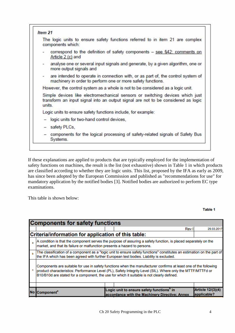
A risk is defined below:
A process to reduce risk is defined as:
Independent safety devices may be used in the design of a safety system. Two such devices are given
below. The first is a safety relay. The second is a two-hand safety circuit. Both are stand-alone and
are not to be incorporated in the PLC system other than as an add-on to an existing PLC system. They
have been supplanted by the safety PLC with the function of these devices incorporated into the PLC
itself after 2003 and the changes in standards permitting safety functions to be allowed inside the PLC.
Since we have heard much from Siemens and Allen-Bradley in this text, we allow another voice –
Schneider – the French automation giant who is the owner of multiple PLCs including the original
PLC – Modicon. The following, however, are not PLCs but rather discrete devices that pre-dated
PLCs for safety functions:

Ch 20 Safety Programming in the PLC 8
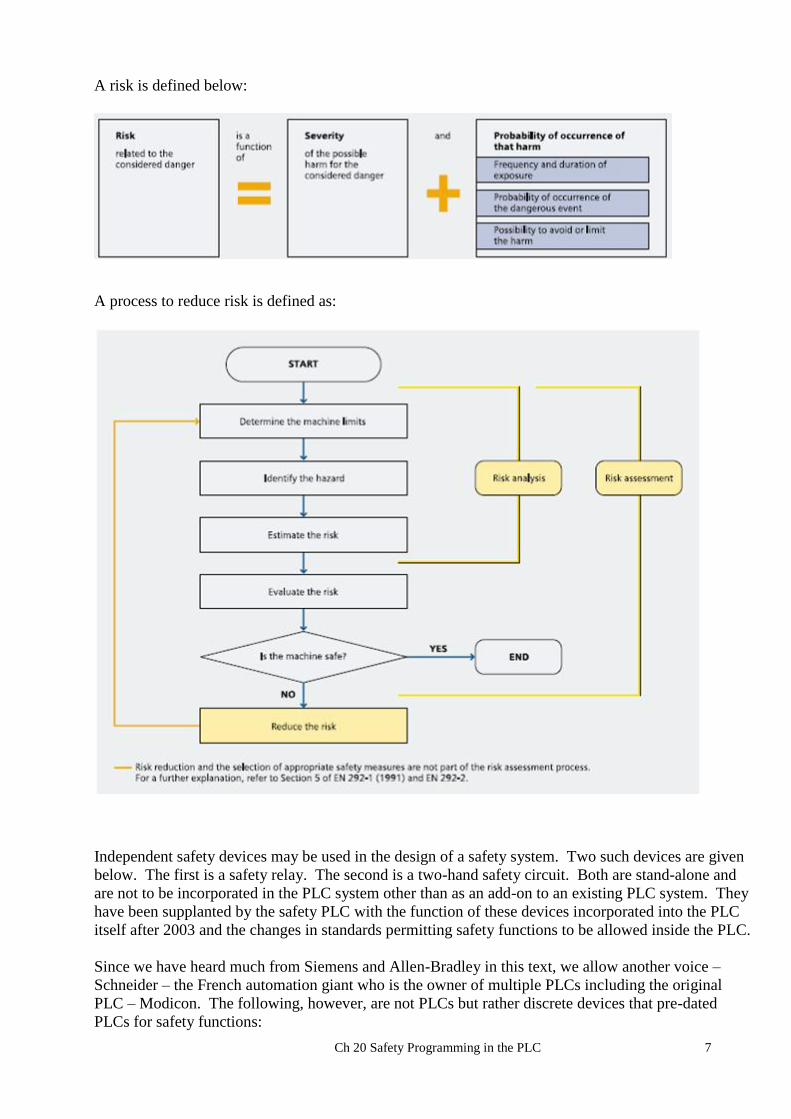
Schneider Electric XPSAC5121P
SAFETY RELAY, OUTPUTS: 3, AUX: 1 SOLID STATE, 24VAC/DC Operating principle
Safety modules XPSAC are used for monitoring Emergency stop circuits conforming to standards
EN/ISO 13850 and EN 60204-1 and also meet the safety requirements for the electrical monitoring of
switches in protection devices conforming to standard EN 1088/ISO 14119. They provide protection
for both the machine operator and the machine by immediately stopping the hazardous movement on
receipt of a stop instruction from the operator, or on detection of an anomaly in the safety circuit itself.
To aid diagnostics, the modules have LEDs which provide information on the monitoring circuit
status.
The XPSAC module has 3 safety outputs and a solid-state output for signaling to the PLC.
Ch 20 Safety Programming in the PLC 9
Ch 20 Safety Programming in the PLC 10
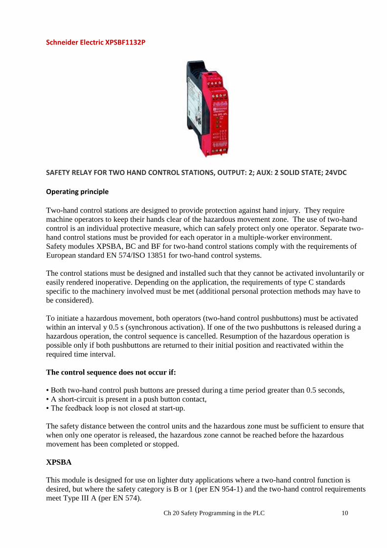
Schneider Electric XPSBF1132P
SAFETY RELAY FOR TWO HAND CONTROL STATIONS, OUTPUT: 2; AUX: 2 SOLID STATE; 24VDC Operating principle Two-hand control stations are designed to provide protection against hand injury. They require
machine operators to keep their hands clear of the hazardous movement zone. The use of two-hand
control is an individual protective measure, which can safely protect only one operator. Separate two-
hand control stations must be provided for each operator in a multiple-worker environment.
Safety modules XPSBA, BC and BF for two-hand control stations comply with the requirements of
European standard EN 574/ISO 13851 for two-hand control systems.
The control stations must be designed and installed such that they cannot be activated involuntarily or
easily rendered inoperative. Depending on the application, the requirements of type C standards
specific to the machinery involved must be met (additional personal protection methods may have to
be considered).
To initiate a hazardous movement, both operators (two-hand control pushbuttons) must be activated
within an interval y 0.5 s (synchronous activation). If one of the two pushbuttons is released during a
hazardous operation, the control sequence is cancelled. Resumption of the hazardous operation is
possible only if both pushbuttons are returned to their initial position and reactivated within the
required time interval.
The control sequence does not occur if:
• Both two-hand control push buttons are pressed during a time period greater than 0.5 seconds,
• A short-circuit is present in a push button contact,
• The feedback loop is not closed at start-up.
The safety distance between the control units and the hazardous zone must be sufficient to ensure that
when only one operator is released, the hazardous zone cannot be reached before the hazardous
movement has been completed or stopped.
XPSBA
This module is designed for use on lighter duty applications where a two-hand control function is
desired, but where the safety category is B or 1 (per EN 954-1) and the two-hand control requirements
meet Type III A (per EN 574).
Ch 20 Safety Programming in the PLC 11
This module is not to be used for applications, such as presses, which require a Type III C
module or where the application is not a category B or 1.
For press applications, for applications in category 2, 3, or 4, or if application calls for a Type III C
module, use XPSBC or XPSBF module.
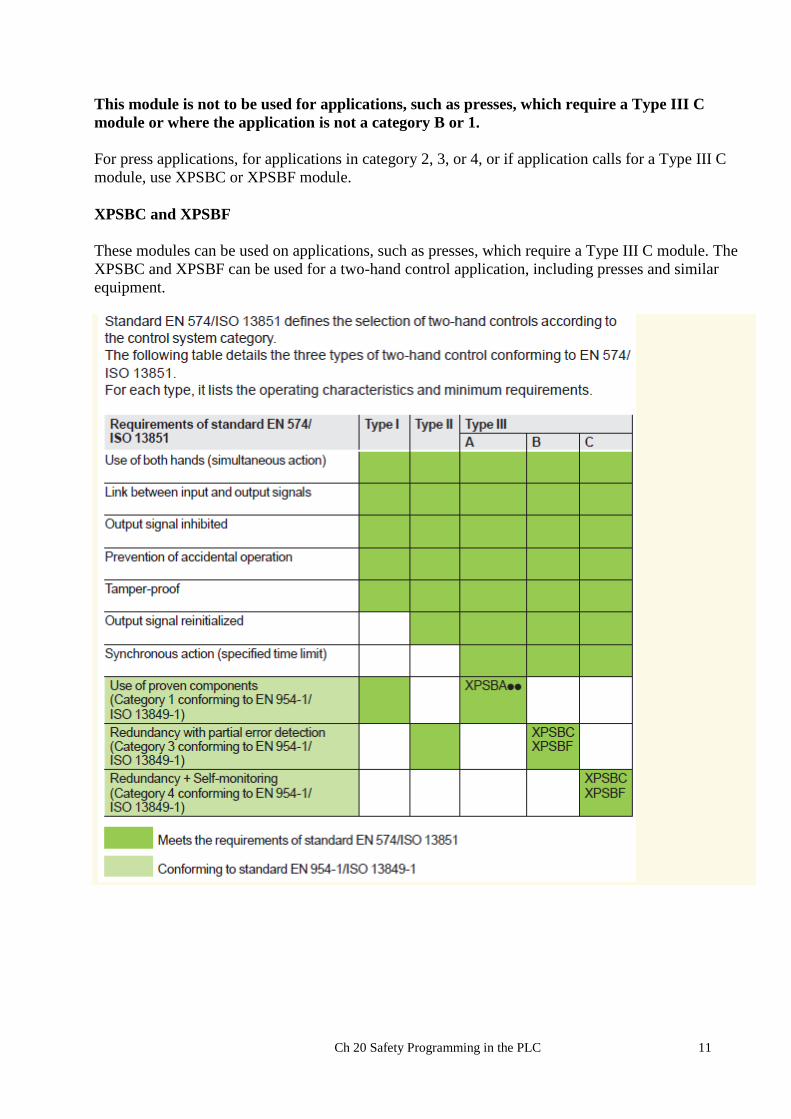
XPSBC and XPSBF
These modules can be used on applications, such as presses, which require a Type III C module. The
XPSBC and XPSBF can be used for a two-hand control application, including presses and similar
equipment.

Ch 20 Safety Programming in the PLC 12
Legal requirements and standards regarding safety at work in North America
An essential difference between the legislation associated with safety at work between North America
and Europe is the fact that in the US there is no standard legislation regarding machinery safety that
addresses the responsibility of the manufacturer/supplier. There is a general requirement that the
employer must provide a safe place of work.
US – general
The Occupational Safety and Health Act (OSHA) from 1970 is responsible in regulating the
requirement for employers to ensure safe working conditions. The core requirements of OSHA are
listed in Section 5 “Duties”:
(a) Each employer
(1) shall furnish to each of his employees employment and a place of employment which are
free from recognized hazards that are causing or are likely to cause death or serious
physical harm to his employees;
(2) shall comply with occupational safety and health standards promulgated under this Act.
The requirements from the OSH Act are administered and managed by the Occupational Safety and
Health Administration. OSHA deploys regional inspectors who check whether workplaces fulfill the
applicable regulations. The regulations, relevant for safety at work of the OSHA, are defined and
described in OSHA 29 CFR 1910.xxx.
The following is stated at the beginning of the regulations for the Safety and Health Program:
(b)(1) What are the employer’s basic obligations under the rule? Each employer must set up a
safety and health program to manage workplace safety and health to reduce injuries, illnesses and
fatalities by systematically achieving compliance with OSHA standards and the General Duty Clause.
And later
(e) Hazard prevention and control
(e) (1) What is the employer’s basic obligation? The employer’s basic obligation is to systematically
comply with the hazard prevention and control requirements of the General Duty Clause and OSHA
standards.
(h)(6)(xvii)
Controls with internally stored programs (e.g., mechanical, electro-mechanical, or electronic) shall
meet the requirements of paragraph (b)(13) of this section, and shall default to a predetermined safe
condition in the event of any single failure within the system. Programmable controllers which meet
the requirements for controls with internally stored programs stated above shall be permitted only if all
logic elements affecting the safety system and point of operation safety are internally stored and
protected in such a manner that they cannot be altered or manipulated by the user to an unsafe
condition.
The OSHA regulations define minimum requirements to guarantee safe places of employment.
However, they should not prevent employers from applying innovative methods and techniques, e.g.
“state of the art protective systems” in order to maximize the safety of employees.

Ch 20 Safety Programming in the PLC 13
In conjunction with specific applications, OSHA specifies that all electrical equipment used to protect
employees, must be certified for the intended application by a nationally recognized testing laboratory
(NRTL) authorized by OSHA. OSHA requires that all electrical products used by employees must be
treated and approved for their intended use by an OSHA Approved Nationally Recognized Testing
Laboratory.
NFPA 79
This Standard applies to the electrical equipment of industrial machines with rated voltages less than
600 V (a group of machines that operate together in a coordinated fashion is considered as a machine).
The comparison of European SIL and US Category (Cat) is shown below. Category 3 and 4 require
safety equipment installed to protect employees.

Ch 20 Safety Programming in the PLC 14
Block Diagram of Siemens PLC Program
While not familiar with Allen-Bradley’s safety PLC, the following article shows some of the concerns
when selecting the best safety PLC for the application. Usually, if one is familiar with Siemens, the
Siemens Safety PLC will be selected. Likewise, with Allen-Bradley, the Allen-Bradley Safety PLC
would be the choice. These tendencies may be strong but should be explored since the safety plc gives
one a good chance to once again ask which PLC is the best overall product for the application.

Ch 20 Safety Programming in the PLC 15
Siemens vs. Rockwell…from a Safety Perspective
Posted by Joan Jacinto on Wednesday, February 25, 2015 · 4 Comments
More than hardware or software, it’s their approach to safety and redundancy that differentiates vendors’ from protocols, controllers,
I/O and networks.
Choosing an industrial equipment supplier is a complex decision, one that can have implications for
years. It’s important to have an understanding of the many tradeoffs that come with this selection
process.
The criterion must cover the myriad aspects of a total solution: global support can be as important as
hardware and software concerns. Each of these three categories has layers of considerations. For many
companies, Siemens and Rockwell are the two primary choices in this selection process.
Based on U.S. customer feedback, Siemens is ahead on the hardware side and Rockwell Automation
has lead on the software side.
Many properties must be examined when product lines are being compared. In recent years, regulators
have made safety an important element in the selection process. In 2008, Rockwell ramped up its focus
on safety with Common Industrial Protocol (CIP) protocol compatibility.
Currently, software V20 version is shipping for Rockwell’s GuardLogix line. It communicates with
GLX controllers and other Ethernet/IP devices via unicast, transmitting safety I/O using DeviceNet.
Rockwell’s safety – line includes modular safety relays. The next step up is the Smart Guard 600,
which uses only DeviceNet. Rockwell does not have local safe I/O with GLX or cGLX, so all safety
communications must be distributed. Drives and safety PLCs remain separate entities, Safety PLCs
with CIP can support up to 64 CIP connections with CIP safety support, using produce/consume to talk
to safety I/O. Transferring data from one processor to the next requires creating a produce/consume tag
every time there is a connection.
The Siemens SIMATIC line has offered PROFIsafe since 1999, enough development time to result in
safety solutions such as PC-based safety, wireless safety and ET200 iSP fail-safe , to name a few. The
wireless capabilities have become increasingly important in recent years as tablets and smart phones
make their way into facilities that also use wireless to put sensors and other gear in hard-to-reach
locations.
The backbone of safety-oriented SIMATIC controllers are standard controllers and standard networks
with safety built into the firmware. Safety signals and control communications both travel over the
same networks, eliminating the need for dedicated networks. The operating system and hardware
Ch 20 Safety Programming in the PLC 16
components have been extended by various protection mechanisms allowing the user to mix and match
standard and safety functionalities in one system.
I/O is another important factor for most industrial environments. Rockwell’s Guard I/O detects failures
at the I/O and field device level, while helping enhance operator protection. Compact Block guard I/O
comes in three flavors: a relay out, input/output card and an input-only card.
Rockwell’s CGLX I/O modules have no onboard communications. Users must buy Ethernet-IP
scanners separately. They are limited to 64 connections. Each safety module takes one connection, and
some safety output modules take up two connections.
Siemens provides flexibility with the ET 200 distributed I/O line. A modular concept lets customers
build configurations that meet their current needs while simplifying expansion as needs change.
PROFINET connections are built in and also a range of Profibus and Profinet cards can be added
quickly for further expansion as required, minimizing downtime.
Fail Safe Operations
The global focus on safety also brings redundancy into more system designs. Many functional safety
requirements call for eliminating single-point failures. Duplicating key elements is an easy way to
avoid problems when a component fails.
SIMATIC controllers also make it simple to add redundancy to ensure unexpected downtime is
minimized. Siemens also provides redundancy support when new versions of its software ship. That’s
a contrast to Rockwell, which typically does not add redundant capabilities with initial software revs,
instead waiting a few months before adding that feature.
Testing is another critical aspect for safe operations. Siemens lets plant operators test standard and
safety software with the PLCSIM simulator tool. It can handle two runtime groups, so one cycle time
can run at different scan time than the other cycle time. For example, an application with100 door
switches can run at 30 ms scan time, while a second with two sets of light curtains can run at 10ms
scan time.
Rockwell has only instance data for add on instructions, so using AOI makes the safety program
cumbersome. There’s no dedicated Rockwell simulation tool. Users must buy the Emulation RSLogix
Emulate 5000 module, which requires a chassis monitor, test stand and Linx Lite for communication.
Ease of configuration is another difference between the two companies/ architectures. Siemens has
safety signatures for all safety FBs. They are safety certified for more precise safety traceability.
Newer modules have no DIP switch settings, which help simplify module replacement, increasing
uptime.
For Rockwell when a project is created, a safety signature is created for the initial download. If another
project is created or a module is changed, the processor’s safety signature has to be changed to add that
module. Users can’t just swap the module out to get running again. With Rockwell systems, standard
tags have to be mapped to safety tags to permit use with safety equipment.
Many other factors will come into play when companies pick their equipment supplier. The difficulty
of configuring and revising systems are important considerations, as is the ability to simulate elements
before they’re implemented. It’s important for companies to have a good understanding of the
available offerings and support services before making decisions that will determine much of the
corporation’s strategic focus for years.
Ch 20 Safety Programming in the PLC 17
Sounds like Siemens influenced this article. Use both and Rockwell has better hardware, software and
technical support. Ethics are completely different also.
Dear Sir or Madam:
–
I enjoyed your article on safety. As I recall, it was the Siemens PLC that was the target of the Stuxnet
attack. PLCs were doing things that no one could see on their PC, damaging equipment. To think,
Siemens PLCs briefly changed the balance of power in the Middle East. Quite an accomplishment. Or
maybe it wasn’t the PLCs. Maybe it was the poorly architected software.
–
Outta Control, LLC
Albuquerque, NM
Alan Peter
I’m using my first Rockwell Safety PLC at the moment and have used Siemens a few times before.
What I find about Rockwell is how inflexible it all seems.
I can’t seem to connect the output of a Safety AOI to a block on the standard but have to map the tag. I
have 3 Safety PLC in my project with 250 CAT3 and CAT4 (DOL, SoftStart and VFD) motors that are
requiring AOIs. I need hundreds of tags mapped.
Fortunately I can do this in the export file and reimport but it is a major pain.
Rockwell always seem to be playing catch-up.
An aside about the comments above:
What is Stuxnet?
From Wikipedia, the following:
Stuxnet is a malicious computer worm, first uncovered in 2010 by Kaspersky Lab. Thought to have been in development since at least 2005, Stuxnet targets SCADA systems and was responsible for causing substantial damage to Iran's nuclear program. Although neither country has openly admitted responsibility, the worm is believed to be a jointly built American/Israeli cyberweapon.[1][2]
Stuxnet specifically targets programmable logic controllers (PLCs), which allow the automation of electromechanical processes such as those used to control machinery on factory assembly lines, amusement rides, or centrifuges for separating nuclear material. Exploiting four zero-day flaws,[3] Stuxnet functions by targeting machines using the Microsoft Windows operating system and networks, then seeking out Siemens Step7 software. Stuxnet reportedly compromised Iranian PLCs, collecting information on industrial systems and causing the fast-spinning centrifuges to tear themselves apart.[4] Stuxnet’s design and architecture are not domain-specific and it could be tailored as a platform for attacking modern supervisory control and data acquisition (SCADA) and PLC systems (e.g., in factory assembly lines or power plants), the majority of which reside in Europe, Japan and the US.[5]Stuxnet reportedly ruined almost one fifth of Iran's nuclear centrifuges.[6] Targeting industrial control systems, the worm infected over 200,000 computers and caused 1,000 machines to physically degrade.[7]
Stuxnet has three modules: a worm that executes all routines related to the main payload of the attack; a link file that automatically executes the propagated copies of the worm; and a rootkit component responsible for hiding all malicious files and processes, preventing detection of the presence of Stuxnet.[8] It is typically introduced to the target environment via an infected USB flash drive. The worm then propagates across the network, scanning for Siemens Step7 software on computers controlling a PLC. In the absence of either criterion, Stuxnet becomes dormant inside the computer. If both the conditions are fulfilled, Stuxnet introduces the infected rootkit onto the PLC and Step7 software, modifying the codes and giving unexpected commands to the PLC while returning a loop of normal operations system values feedback to the users.[9][10]

Ch 20 Safety Programming in the PLC 18
In 2015, Kaspersky Labs noted that the Equation Group had used two of the same zero-day attacks, prior to their use in Stuxnet, and commented that: "the similar type of usage of both exploits together in different computer worms, at around the same time, indicates that the Equation Group and the Stuxnet developers are either the same or working closely together".[11]
So, buyer – beware!
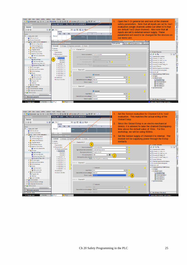
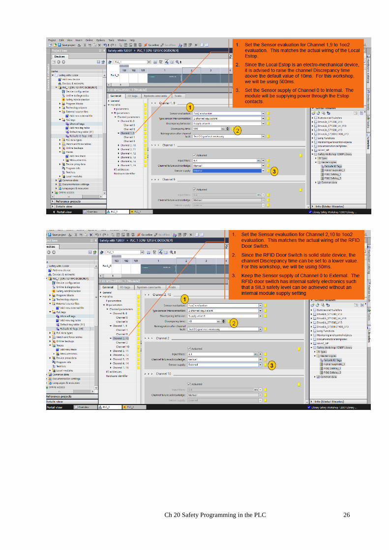
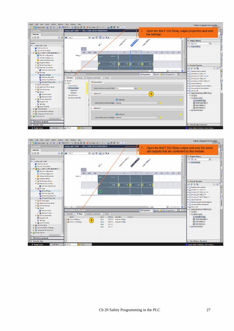
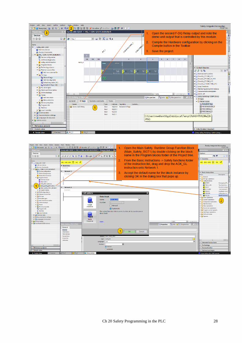
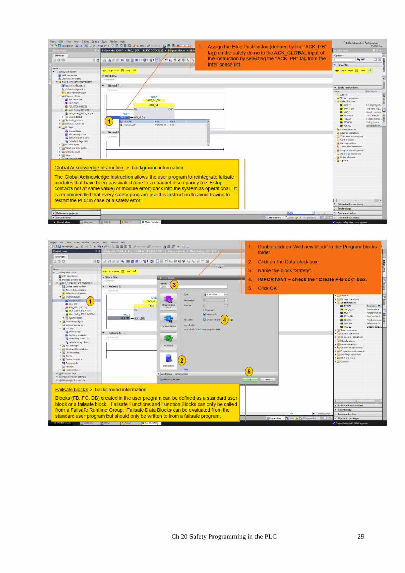
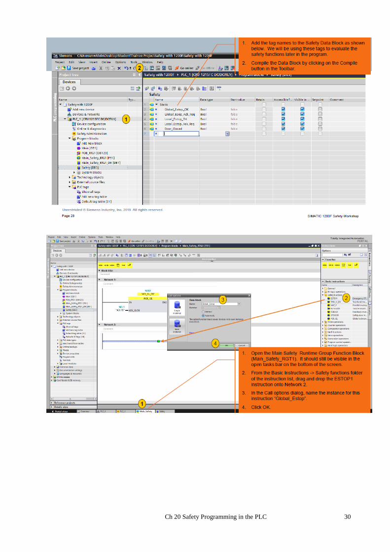
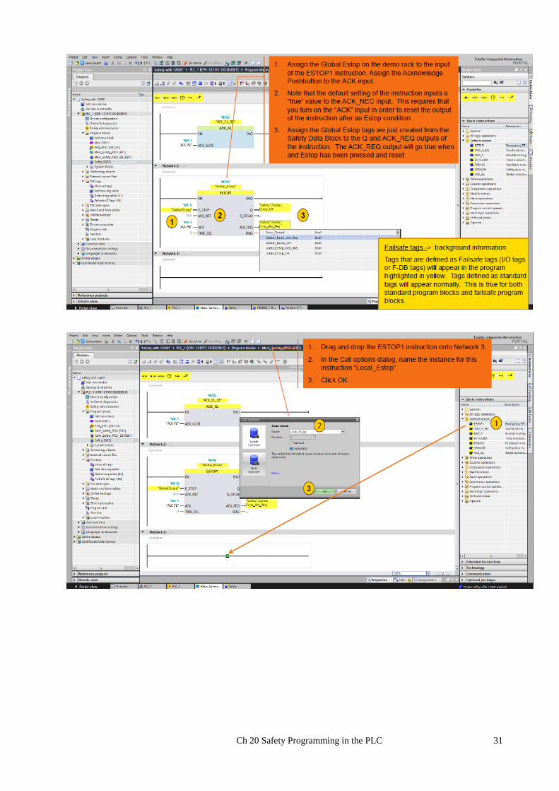
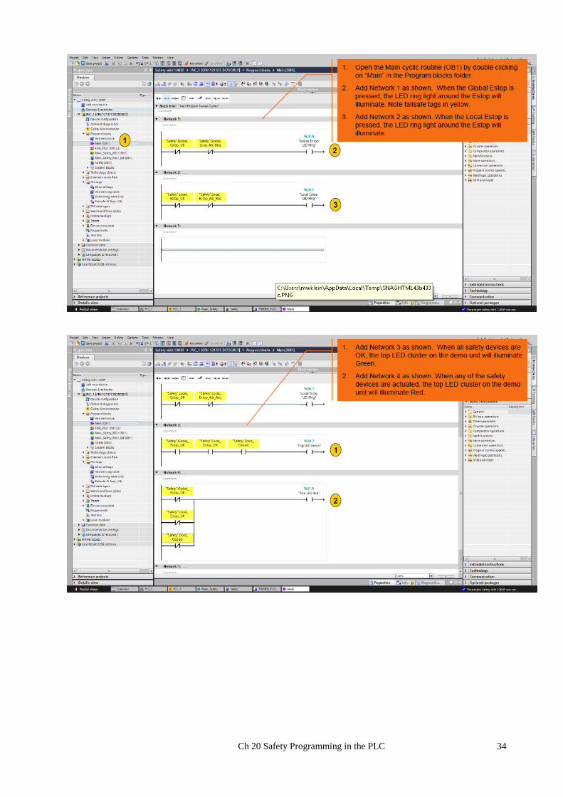
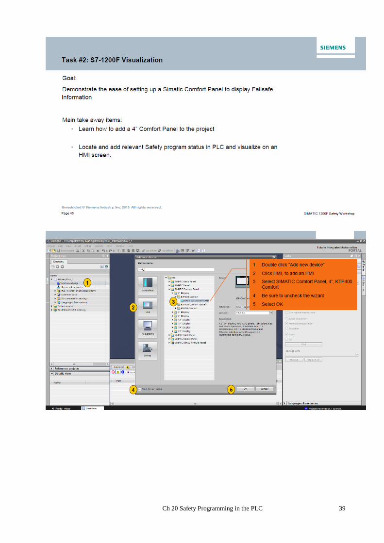
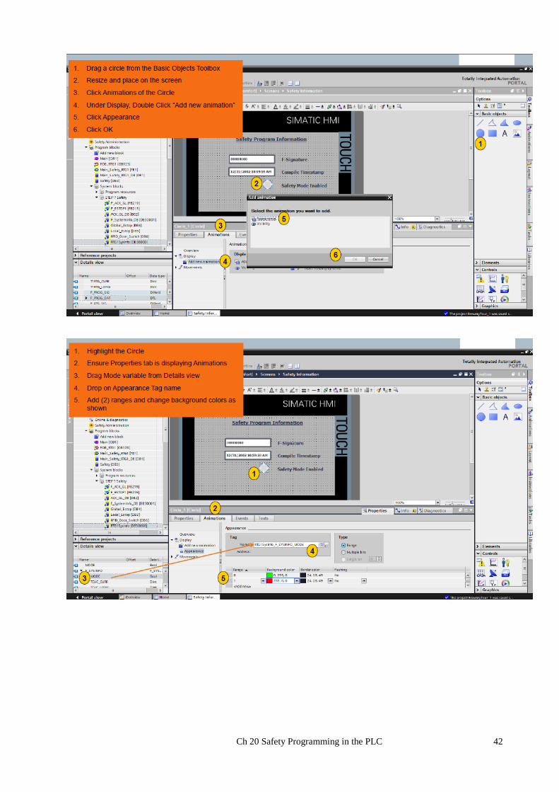
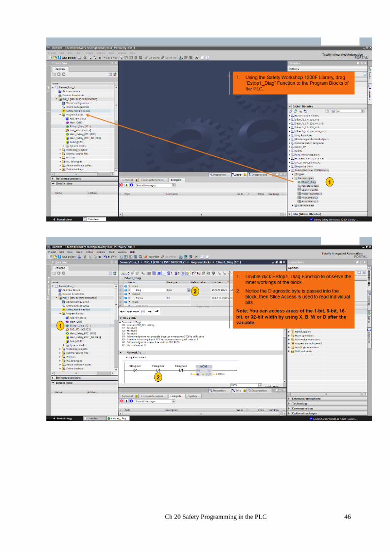
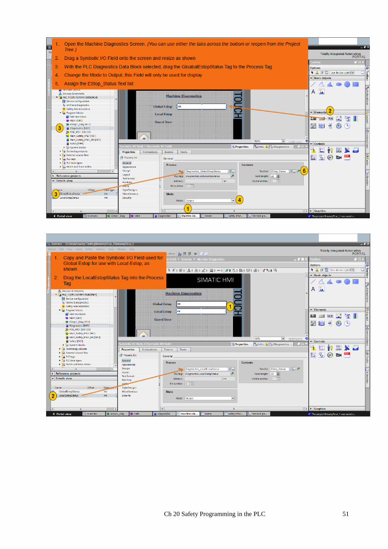
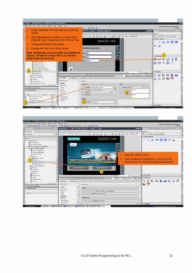
The following is a lab furnished by Siemens to demonstrate the functionality of their safety equipment.
Without many comments, the following is re-produced to give an example of safety programming and
configuring:
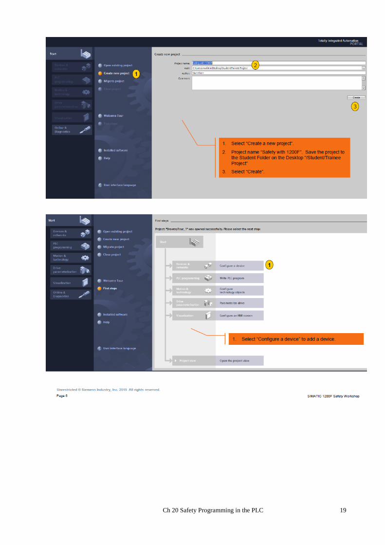
Ch 20 Safety Programming in the PLC 19
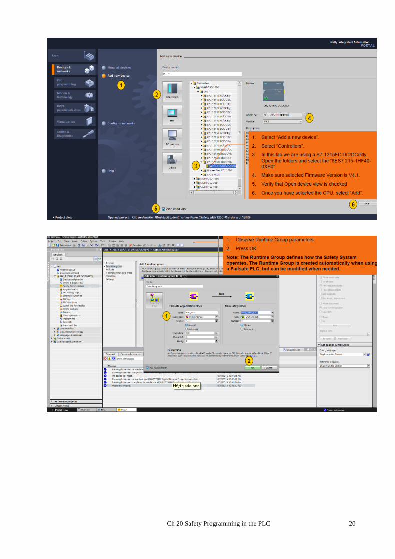
Ch 20 Safety Programming in the PLC 20

Ch 20 Safety Programming in the PLC 21
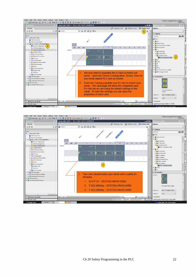
Ch 20 Safety Programming in the PLC 22

Ch 20 Safety Programming in the PLC 23
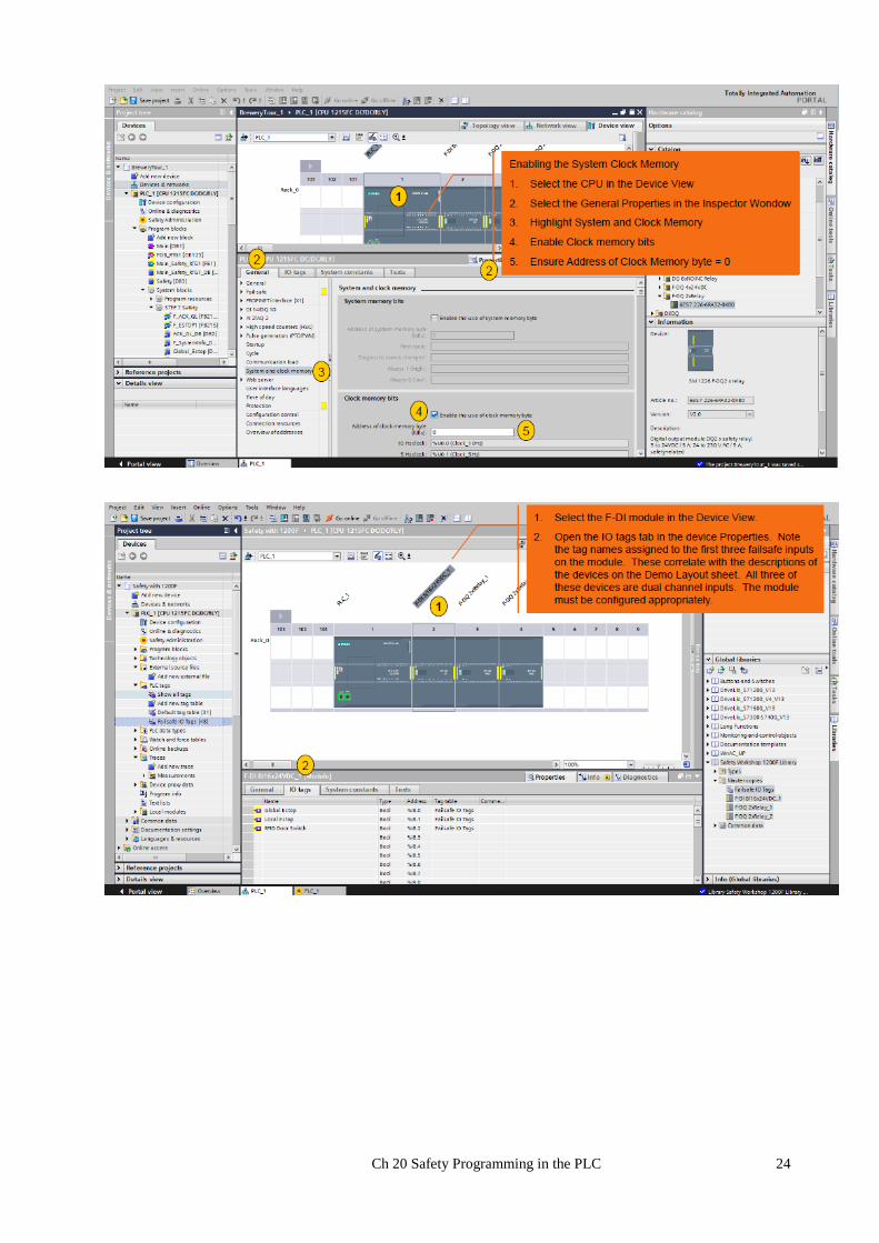
Ch 20 Safety Programming in the PLC 24
Ch 20 Safety Programming in the PLC 25
Ch 20 Safety Programming in the PLC 26
Ch 20 Safety Programming in the PLC 27
Ch 20 Safety Programming in the PLC 28
Ch 20 Safety Programming in the PLC 29
Ch 20 Safety Programming in the PLC 30
Ch 20 Safety Programming in the PLC 31

Ch 20 Safety Programming in the PLC 32

Ch 20 Safety Programming in the PLC 33
Ch 20 Safety Programming in the PLC 34

Ch 20 Safety Programming in the PLC 35

Ch 20 Safety Programming in the PLC 36

Ch 20 Safety Programming in the PLC 37

Ch 20 Safety Programming in the PLC 38
Ch 20 Safety Programming in the PLC 39

Ch 20 Safety Programming in the PLC 40

Ch 20 Safety Programming in the PLC 41
Ch 20 Safety Programming in the PLC 42

Ch 20 Safety Programming in the PLC 43

Ch 20 Safety Programming in the PLC 44

Ch 20 Safety Programming in the PLC 45
Ch 20 Safety Programming in the PLC 46

Ch 20 Safety Programming in the PLC 47

Ch 20 Safety Programming in the PLC 48

Ch 20 Safety Programming in the PLC 49

Ch 20 Safety Programming in the PLC 50
Ch 20 Safety Programming in the PLC 51
Ch 20 Safety Programming in the PLC 52

Ch 20 Safety Programming in the PLC 53
The examples of this lab give an insight into the implementation of a Safety PLC and its components.
Next will be a review of the process of determining whether the effort is needed – a risk assessment.
The article found is informative and general enough to give a good over-view. Using the combination
of the BGIA – German rule set along with common sense and those rules developed by a particular
industry will give a good foundation for implementing a safe PLC and safe process. Realize that this
effort is on-going and will continue to be a source of concern even after the start-up of a process.
Ch 20 Safety Programming in the PLC 54
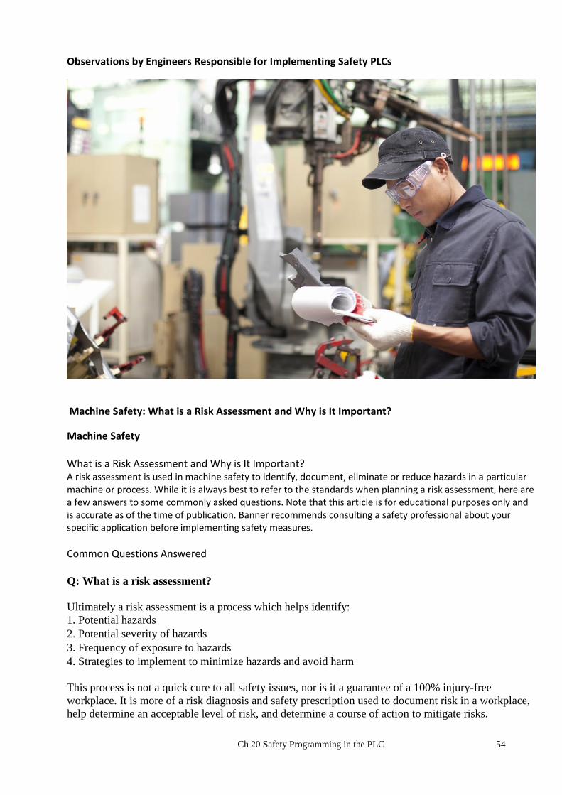
Observations by Engineers Responsible for Implementing Safety PLCs
Machine Safety: What is a Risk Assessment and Why is It Important?
Machine Safety What is a Risk Assessment and Why is It Important? A risk assessment is used in machine safety to identify, document, eliminate or reduce hazards in a particular machine or process. While it is always best to refer to the standards when planning a risk assessment, here are a few answers to some commonly asked questions. Note that this article is for educational purposes only and is accurate as of the time of publication. Banner recommends consulting a safety professional about your specific application before implementing safety measures.
Common Questions Answered Q: What is a risk assessment?
Ultimately a risk assessment is a process which helps identify:
1. Potential hazards
2. Potential severity of hazards
3. Frequency of exposure to hazards
4. Strategies to implement to minimize hazards and avoid harm
This process is not a quick cure to all safety issues, nor is it a guarantee of a 100% injury-free
workplace. It is more of a risk diagnosis and safety prescription used to document risk in a workplace,
help determine an acceptable level of risk, and determine a course of action to mitigate risks.

Ch 20 Safety Programming in the PLC 55
Q: What steps must be taken in a risk assessment? The fundamental steps in the risk assessment process include:
1. Identifying tasks and the associated hazards in the workplace
2. Assessing the probability and severity of harm
3. Reducing the risk of harm through the elimination of the hazard or through the use of safeguarding
methods
4. Documenting the process and the results.
Through the risk assessment process and the documentation it produces, a machine manufacturer and
an employer can prove due diligence in providing a safe work place and a quality product.
Q: What standards should be followed?
There are many standards! Among them:
ANSI/RIA R15.06 -1999, Safety Requirements for Industrial Robots and Robot Systems
ANSI B11 TR3, Risk Assessment and Risk Reduction
ISO 14121(EN 1050), Principles of Risk Assessment
OSHA 3071 Job Hazard Analysis
IEC 812 FMEA
Also refer to EN 1050 and ISO 13849-1 which outline the process of risk assessment and specific
categories of safety equipment. Standards help define a cohesive strategy or approach to the risk
assessment process, which, if followed, can lead to better decisions and more efficient utilization of
resources.
Q: Does OSHA endorse any certain standard?
OSHA (Occupational Safety and Health Administration) does not provide a prescription, but it does
provide the objective. It is a general expectation that industry-recognized abatement methods will be
applied whenever and wherever feasible.
Q: Who is responsible for conducting a risk assessment? In the US, ANSI (American National Standards Institute) standards that define Risk Assessment, such
as B100.0 2010 as well as RIA 15.06 2012, require that both the machine supplier and the user have
responsibilities towards ensuring safety. OSHA strongly recommends that a risk assessment be
conducted and that it should include the implementation of a plan for risk mitigation and that the entire
process should be thoroughly documented to demonstrate due diligence. In the EU, the machine
supplier is primarily responsible for ensuring that a safe machine is shipped. They will typically be the
ones who conduct the basic risk assessment.
Q: Who should be involved in the risk assessment process? Choose a diverse and well-respected group of individuals. Operators, maintenance, electrical,
mechanical engineers, shift leads, production supervisors, and health and safety professionals are all
potential candidates. These individuals should be empowered by an officer of the company who has
the responsibility of allocating resources. Management must provide visible leadership to make this
process credible.
Q: Can a consultant be hired to carry out a risk assessment? Competent consultants can greatly enhance the risk assessment process, but the final responsibility for
personnel safety is still that of the employer. Employees should also be trained to recognize hazards
and act appropriately.

Ch 20 Safety Programming in the PLC 56
Q: When should a risk assessment be conducted? Ideally a risk assessment should be conducted whenever changes are made, especially when new
machinery or systems are introduced, new tasks are added or a new routine is devised. When adding
new processes, evaluate what tasks may create the probability of a hazardous event.
Q: What needs to be assessed? Everything should be assessed, not just the potential hazards. Look at the work environment,
ergonomics, noise, etc. Keep all that in mind, in case of a violation or litigation, one must be able to
demonstrate that the risk assessment was sufficient for the given hazard.
Q: How should this process begin? The first thing that should be done is to get buy-in from front-line employees by explaining that the
goal of a risk assessment is to have a workplace free of hazards. It should be emphasized that each
employee is responsible for his/her own safety. It is a responsibility of the employee to report any
recognized hazards.
Q: What can be done to reduce the risk of injury on hard-to-guard hazardous machines? Do what is feasible from a design standpoint. Implement safeguards, use personal protective
equipment, raise the general level of awareness of the hazard, and develop safe work procedures for all
tasks where the hazard cannot be eliminated or controlled. The end result should be to achieve a
tolerable level of risk.
Q: How should risks be prioritized? Priority should always be given to the highest risk hazard. An ergonomic work station is less of a
priority than an unguarded stamp press.
Q: How do you determine which hazards are worse than others? Industry risk assessment models are designed to assist with this process.
Q: What industries use risk assessments?
Risk assessments are conducted in many different industries where work place accidents must be
minimized and where product quality and performance are critical. Some of these industries have made
an effort to standardize a process for evaluating risk, including:
Metal forming/cutting
Medical devices
Robotics
Insurance
Aerospace
Semiconductor
Transportation
Q: Do small companies need to record the results of a risk assessment?
Yes, it is strongly recommended that all companies, regardless of size, thoroughly document any risk
assessments that they conduct. If a safety-related incident should happen to occur, this documentation
can be used to demonstrate that a risk assessment was done properly and that all necessary risk
mitigation strategies were put into place.
Q: Do OEMs need to perform a risk assessment?

Ch 20 Safety Programming in the PLC 57
Yes. It is a minimum responsibility to consider risk associated with all reasonably foreseeable use
and/or misuse of equipment and to design out or minimize these risks where feasible. OEMs have a
duty to their customers to make them aware of any residual risk associated with the operation of
equipment.
The end-user should reduce any further identified risk through additional safeguards and
administrative measures including supervision, warning signs, and training.
Q: How can the accuracy of a risk assessment be verified?
Generally, a risk assessment can be considered accurate if it can be demonstrated that all the minimum
requirements established by an industry have been met or exceeded and that results are periodically
reviewed and confirmed.
Q: How can one be certain of compliance with standards in other countries?
Most countries have adopted ISO (International Organization for Standardization) standards. If you
have conducted a good risk assessment, it will satisfy standards in most countries.
Q: Where does a risk assessment fit into the safety program?
A risk assessment is listed In OSHA’s proposed safety program rule as the second of the five core
elements of a safety program. It immediately follows management leadership and employee
participation.
Q: What is an FMEA?
A Failure Mode and Effect Analysis (FMEA) is one specific procedure used to conduct a risk analysis.
When identifying hazards, it is sometimes necessary to look systematically at the components that
control the hazard or protect people from the hazard. Valves slow down, brakes wear out, mechanical
door switches can fail, etc. If components are relied upon for safety, the failure modes and their effect
on safety must be analyzed.
Ch 20 Safety Programming in the PLC 58
Summary
The chapter tries to define the type of safety needed in the factory. There is no need to provide the
same equipment as is provided for a rocket to the moon – especially one carrying human cargo.
However, equipment is to be safe and the need for safe PLCs has grown through the years.
The German BGIA approach is introduced. If one were to design a system especially for the European
market, these documents would be essential. Moving the machine from Europe to the US will show
many of the techniques employed to meet the standards of the EU.
There is included a major lab demonstrating the implementation of the safe PLC by Siemens. The S7-
1200 is used. Version 14 software is available. GO FOR IT!

Ch 20 Safety Programming in the PLC 59
Lab
Ch 20 Safety Programming in the PLC 60
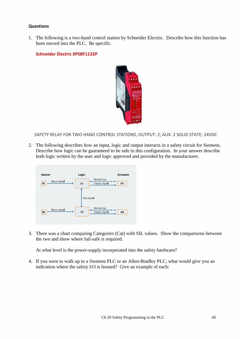
Questions 1. The following is a two-hand control station by Schneider Electric. Describe how this function has
been moved into the PLC. Be specific.
Schneider Electric XPSBF1132P
SAFETY RELAY FOR TWO HAND CONTROL STATIONS, OUTPUT: 2; AUX: 2 SOLID STATE; 24VDC
2. The following describes how an input, logic and output interacts in a safety circuit for Siemens.
Describe how logic can be guaranteed to be safe in this configuration. In your answer describe
both logic written by the user and logic approved and provided by the manufacturer.
3. There was a chart comparing Categories (Cat) with SIL values. Show the comparisons between
the two and show where fail-safe is required.
At what level is the power-supply incorporated into the safety hardware?
4. If you were to walk up to a Siemens PLC or an Allen-Bradley PLC, what would give you an
indication where the safety I/O is housed? Give an example of each: