chapter 2 strongly coupled organic microcavities€¦ · 2 strongly coupled organic microcavities...
TRANSCRIPT

39
Chapter 2Strongly Coupled Organic Microcavities
Paolo Michetti, Leonardo Mazza and Giuseppe C. La Rocca
© Springer-Verlag Berlin Heidelberg 2015 Y.S. Zhao (ed.), Organic Nanophotonics, Nano-Optics and Nanophotonics, DOI 10.1007/978-3-662-45082-6_2
Abstract The photophysics of planar microcavities which employ organic materials as the optically resonant medium to achieve the strong-coupling regime is discussed. While as a result of the light–matter coupling, cavity polariton branches appear which are analogous to those observed in inorganic microcavities, many properties of organic-based microcavities are qualitatively and quantitatively different. The electronic excitations involved are molecular Frenkel excitons, rather than large radius Wannier excitons, which lead to large Rabi splitting values. The effects of dis-order are typically much more pronounced as well as the exciton-phonon coupling, possibly leading to vibronic replicas. As a consequence, polariton relaxation and polariton-polariton scattering mechanisms also show features specific to the organic material employed. The field of organic-based microcavities is attracting an increas-ing interest as high excitation density phenomena such as polariton lasing have recently been reported. In view of their experimental relevance, two different kinds of organic microcavities, disordered J-aggregate-based microcavities and crystalline anthracene microcavities, are considered.
2.1 Introduction
The effort to improve the performance of optoelectronic devices drives the ongoing research of novel materials and architectures. In order to tame the light–matter interaction, while, on the one hand, compounds with improved linear and
P. Michetti (*) Institut für Theoretische Physik, Technische Universität Dresden, 01062 Dresden, Germanye-mail: [email protected]
L. Mazza NEST, Scuola Normale Superiore and Instituto Nanoscienze—CNR, 56126 Pisa, Italye-mail: [email protected]
G.C. La Rocca Scuola Normale Superiore and CNISM, Piazza dei Cavalieri 7, 56126 Pisa, Italye-mail: [email protected]

40 P. Michetti et al.
nonlinear optical properties have been synthesized, on the other hand, dielec-tric microstructures have been developed engineering the photonic dispersion law and density of states (DOS), a paramount instance being photonic crys-tals. Rather than tailoring each of the two players—matter and light—individu-ally to stretch the rules that govern their interaction, an alternative approach is to blend them together into hybrid entities—the polaritons—exhibiting novel potentialities.
This is precisely what happens in a high finesse microcavity (MC) in which the cavity mode is resonant with a narrow electronic excitation such that their cou-pling overcomes the damping mechanisms. In this strong-coupling regime, the rel-evant eigenmodes are no longer photons and the excitons individually, but rather their coherent superpositions, i.e., the lower polariton (LP) and the upper polariton (UP) modes, which become the key players.
2.1.1 Inorganic Microcavities
Strongly coupled MCs based on inorganic semiconductors have been investigated since the early 1990s culminating with the recent observation of macroscopic quantum coherent effects such as Bose-Einstein Condensation (BEC) of cavity polaritons (see, e.g., the reviews in [1–3]). The polariton notion in bulk crystals is a traditional one [4], and in inorganic semiconductors, it comprises both the case of exciton-polaritons, wherein the matter excitation is a large radius optically allowed Wannier exciton [5], and of phonon-polaritons, wherein the matter excita-tion is an optical phonon in a polar lattice [6]. Bulk polaritons are characterized by a conserved three-dimensional (3D) wave vector and are not easily accessible experimentally. In typical planar microcavities, instead, a quantum well exciton is coupled to a cavity photon, and cavity polaritons are characterized by a two-dimensional (2D) in-plane wave vector. In particular, if the cavity mode cutoff energy at vanishing in-plane wave vector is lower than the exciton energy (i.e., for a negatively detuned cavity), for increasing in-plane wavevectors, the cavity photon steep dispersion and the flat exciton dispersion would cross each other, but in the strong-coupling regime, the UP and LP branches do anticross: Their separa-tion is the Rabi splitting, proportional to the square root of the exciton oscillator strength (OS).
The MC mirrors which are usually distributed Bragg reflectors are not totally reflecting and the cavity polaritons are very weakly coupled to the 3D free-space photons having a matching in-plane wave vector and a vertical wave vector (which is not conserved) dictated by energy conservation. Injection and detec-tion of cavity polaritons can thus be directly accomplished via angle-dependent spectroscopy, and angle-resolved reflectivity spectra are routinely employed to map the cavity polariton dispersion. The typical signature of the strong-coupling regime is a doublet of reflectivity dips, as first observed by Weisbuch et al. [7] (see Fig. 2.1).

412 Strongly Coupled Organic Microcavities
While bulk polaritons have a lower branch with an energy linearly vanishing at small wave vectors, cavity polaritons have a lower branch with a minimum energy (which for a resonant cavity is the cavity mode cutoff energy minus half the Rabi splitting) and in its vicinity, a parabolic dispersion with a very small mass, deter-mined by the steep cavity mode dispersion, which flattens out as soon as the in-plane wave vector increases. Cavity polaritons behave as bosonic particles and, differently from free photons in vacuum, have a finite lifetime (due to leakage through the mirrors and exciton non-radiative recombination) and mutual inter-actions (due to the exciton-exciton scattering). Under resonant or non-resonant pumping, a bosonic-stimulated buildup of cavity polaritons at the bottom of the LP branch may occur leading eventually to a Bose-Einstein condensate—as first observed by Kasprzak et al. in 2006, see Fig. 2.2—and to superfluidity. From the technological viewpoint, interest in such phenomena has also been triggered by polariton lasing whereby the light emitted through the cavity mirrors inherits the coherence properties of the polariton ensemble. The field of inorganic-based MCs has flourished in recent years, and important new results keep being reported.
2.1.2 Organic and Hybrid Microcavities
An intrinsic limitation of inorganic-based MCs is the weak binding energy of Wannier excitons and their small OS leading to Rabi splitting values typically of the order of 10 meV. Much larger Rabi splitting values have been anticipated for MCs based on molecular Frenkel excitons [9] and already in the pioneer-ing experiment by Lidzey et al. [10] , a Rabi splitting as large as 160 meV has
Fig. 2.1 Low-temperature reflectivity of a strongly coupled MC containing 7 GaAs quantum wells. The three spectra correspond to different cavity detunings: Spectrum 2 is on resonance and directly shows the Rabi splitting (Adapted from [7], Copyright 1992, with the permission of The American Physical Society)

42 P. Michetti et al.
been observed [10] employing a porphirine molecule (4TBPPZn) blended in a polysterene film as optically resonant material at room temperature. Since then, strongly coupled MCs have been demonstrated using a variety of organic mate-rials (see, e.g., the reviews in [11–13]) which can be either classified as non-crystalline, e.g., J-aggregate blends, or (poly)crystalline, e.g., naphtalene and anthracene [14]. The knowledge accumulated for inorganic MCs can only par-tially be useful to understand organic MCs because, in particular, disorder effects and the electron–phonon interaction are much stronger [4, 14]. While the field of organic-based microcavities has not yet reached a maturity comparable to that of inorganic ones, very recently manifestations of nonlinearities and bosonic stimu-lation of organic cavity polaritons have been reported and attracted much atten-tion [15–17].
The strategy of combining in the same MC organic and inorganic optically resonant media has also been fruitfully pursed to realize hybrid cavity polaritons [18, 19] as earlier theoretically suggested [9]. Organic–inorganic systems may capitalize on the best properties of either constituent, such as the large OS and quantum yield of organics on the one hand and the good electrical injection and transport properties of inorganic semiconductors on the other one. In strongly coupled hybrid MC, the cavity mode and both the Frenkel and Wannier excitons coherently mix so that the hybrid cavity polaritons share the properties of both of them.
Hybrid systems and MCs have been reviewed in [13]. Here, our current under-standing of organic microcavities is discussed considering as illustrative examples of non-crystalline and crystalline systems disordered J-aggregate MCs and crystal-line anthracene MCs, respectively, because of their experimental relevance. The field indeed appears ripe for further theoretical and experimental developments which promise to rival those of inorganic MCs.
Fig. 2.2 Low-temperature angular distribution of light emitted by the LPs in a CdTe-based MC within a 23° cone around the normal direction following non-resonant excitation. The three spectra from left to right correspond to an excitation power below, at and above the threshold intensity IS for BEC, the latter case being dominated by the emission from polaritons with a van-ishing in-plane wavevector. (Adapted from [8], Copyright 2006, with permission of Macmillan Publishers Ltd: Nature)

432 Strongly Coupled Organic Microcavities
2.2 Amorphous J-Aggregate Microcavities
J-aggregates thin films represent the most commonly employed class of amor-phous organic optically active materials for the realization of strongly coupled sys-tems [20–22]. J-aggregates are obtained as a result of the aggregation of specific organic dyes (i.e., cyanine dyes) in polar solvents, under appropriate conditions. Upon aggregation, the optical features of the system spectacularly change into narrow and intense absorption and emission lines characterized by a very weak Frank-Condon shift, due to the rigidity of the molecular chain. These optical fea-tures are well understood as a manifestation of superradiance phenomena typical of one-dimensional Frenkel exciton systems [23]. At sufficiently low concentra-tion, in order to avoid strong inter-aggregate interaction (and therefore the broad-ening of the resonance line), J-aggregates are randomly arranged in an inert host matrix. Because of their optical features, such organic materials are ideal for the observation of strong light–matter coupling. A concrete example for a J-aggregate MC structure is presented in Fig. 2.3.
The following discussion is meant to provide an introduction to the physics of J-aggregate MCs. In Sect. 2.2.1, we more broadly discuss the effect of disorder in amorphous MCs, analyzed with a minimal model [24], where an inhomogeneously broadened ensemble of two-level chromophores undergos strong light–matter cou-pling. In Sect. 2.2.2, we present a theoretical model [25] of the photo-excitation dynamics of J-aggregate MCs under non-resonant pumping. This model is particu-larly instructive, because it allows the simulation of the photoluminescence (PL) of an organic MC, starting from a microscopical description of the bare optically active material.
Fig. 2.3 Example of an experimental structure of a J-aggregate MC consisting of a 220-nm-thick layer of TDBC J-aggregate dispersed in a polyvinyl alcohol matrix between two niobia–silica distributed Bragg reflectors (DBRs) of 11λ/4 pairs. (Adapted from [26], Copyright 2011, with permission of WILEY-VCH Verlag, Advanced Functional Materials)

44 P. Michetti et al.
2.2.1 Disorder Effects
In organic-based MCs, the optically active electronic resonances are quite dif-ferent with respect to the inorganic ones, being molecular excitations rather than large radius excitons. In particular, due to electron–phonon interaction or disor-der scattering the molecular Frenkel excitons may behave as incoherent (diffusive) excitations rather than Bloch plane waves having a well-defined wave vector and group velocity [27]. Moreover, excitons in molecular amorphous materials, such as J-aggregate dispersed in an host matrix, are by their nature localized within a molecular aggregate with typical extensions around tens of nm. It is only the light–matter interaction that, in strong-coupling, polarizes the medium giving birth to delocalized polaritons with a well-defined wave vector. Therefore, amorphous organic films intrinsically introduce excitonic disorder of orientational, positional, and diagonal kind in the strongly coupled system. The molecules are in fact ran-domly arranged in the host matrix, at least at low concentration, where ordering phenomena do not arise (such as liquid crystal arrangements). Each molecule feels a different environment, thus their molecular resonance energies are shifted with respect to their average transition energy, resulting in a static inhomogene-ously broadened excitonic resonance, also at low temperature. At finite tempera-ture, dynamical disorder, due the presence of vibrations, can also contribute to the inhomogeneous linewidth. Structural disorder scattering breaks the translational invariance and the coherence (in this context, a coherent state is a delocalized plane-wave-like state of definite momentum) imposed by the medium polariza-tion due to light–matter interaction, bringing about localized states quite different from plane-wave-like polaritons [24, 28]. On the other hand, orientational disor-der restores a macroscopic rotational symmetry in the plane of the film, which is generally absent in an organic crystalline environment, characterized, instead, by a strong anisotropy of the optical features.
A macroscopic approach to disorder consists in solving Maxwell equations for a transverse electromagnetic wave in presence of a broad and dispersionless exci-tonic resonance [4, 28]. This provides a first insight on the effect of disorder in a strongly coupled system. The equation for a wave of in-plane momentum q and frequency ω = E/� assumes the form
with the Rabi splitting �2 = fex4εb
, being fex the OS of the excitonic resonance line at energy Eex and εb the background dielectric constant, where Eph(q) is the disper-sion of the cavity mode and γex the total broadening of the excitonic resonance. Equation (2.1) is solved for the real energies, giving the UP (sign +) and LP polariton (sign −) dispersion curves E±(q) [see (2.9)], and for their imaginary part δE±(q), accounting for the energy uncertainty. One obtains that the energy uncer-tainty δE±(q) = γexC
(ex)± (q) is simply proportional to the exciton content of the
polaritonic state [see (2.8)]. For a given wave vector, the momentum uncertainty can be quantified through the group velocity
(2.1)[
E − Eph(q)]
(E − Eex + iγex) = �2/4,
452 Strongly Coupled Organic Microcavities
and regions where polaritons possess quality of ‘good’ quasi-particles must sat-isfy δq < q. This procedure allows to determine a minimum and a maximum end-point on the LP branch. Inside this range, polaritons have a coherent (delocalized) nature, while polariton localization occurs outside this region. Similarly, a mini-mum endpoint is defined for the UP branch, above which polaritons have a coher-ent nature.
Numerical and analytical results [24, 29–32] have confirmed the validity of the macroscopic model (see the following discussion in this section) and analyzed the effect of different kinds of structural disorder. Special attention has been given to the case of the disorder scattering at the bottom of the LP branch that, possessing small group velocity, is especially susceptible to suffer localization. Evidences of localized polaritons in J-aggregates have been found analyzing the reflectivity and luminescence spectra, in which a third peak between the UP and the LP branches appears [33]. This third emission peak at energy near the bare exciton resonance is found at all external angles and, being the angle related to the in-plane wave vec-tor, we can associate it to states of high wave vector uncertainty, therefore local-ized for the uncertainty principle.
Now, following [24], we set up a minimal quantum mechanical model for a one-dimensional MC of length L. The MC contains two kinds of one-excitation states: N localized excitons (two-level chromophores) placed at sites ri and delo-calized photon modes, coupled by the light–matter interaction. The system is described by the model Hamiltonian (neglecting all damping processes)
where cq is the annihilation operator for a photon of in-plane momentum q and bj the annihilation operator acting on the molecular exciton at the j-th site. The excitonic energies Ej have a random Gaussian distribution around their average value Eex, with standard deviation σ. We apply cyclic boundary conditions for the photons so that allowed wavevectors are q = 2πn/L with n ∈ N. A direct diago-nalization gives us access to the polariton eigenmodes of the system (which we arbitrarily define as the modes having a photon content larger then 5 %), which we can then completely analyze.
In an ideal situation Ej = Eex and rj = j L/N for j = 0, 1, . . . ,N − 1, after introducing the momentum basis for the exciton operators
(2.2)δq±(q) ≈ δE±(q)/�v±(q)
(2.3)v±(q) =1
�
dE±(q)
dq,
(2.4)H =∑
q
Eph(q)c+q cq +
∑
j
Ejb+j bj +
∑
q,j
(
Vj,qc+q bj + h.c.
)
(2.5)Vj,q =�
2√Ne−iqrj ,
46 P. Michetti et al.
the system eigenstates are described by ideal cavity polaritons (ICPs)
where the exciton and photon content is given by the Hopfield coefficients
and the corresponding eigenenergies are
In Fig. 2.4a, b, we present the analysis of the eigenstates for a single realization of the model in (2.5) with on-site energetic disorder. Plotting the eigenenergies against the average wave vector (calculated on the photonic component of the eigenstates) of eigenstates with photon component larger than 5 %, we easily iden-tify the upper and LP branches. Between the two branches, we note the presence of a large number of eigenstates, corresponding to energies similar to the bare excitation energy of the chromophores. Plotting the excitonic content of the eigen-states (in Fig. 2.4a), we note that such states are mostly exciton-like. The analysis of the standard deviation of the wave vector calculated on the photonic component [in Fig. 2.4b] reveals that these states have an incoherent nature (they do not have a well-defined momentum). Experimentally, this is consistent with the measure-ment of a PL peak for frequencies between the polariton branches, persisting at all observation angles [33]. In Fig. 2.4c, we plot the mean extension of the polari-tonic states averaged on 5,000 disorder configurations. This analysis confirms the existence of localized states with finite exciton–photon mixing between the two polariton branches (at energies near the bare exciton resonance) and at the bottom of the LP branch, and hence the validity of the previously discussed macroscopic approach.
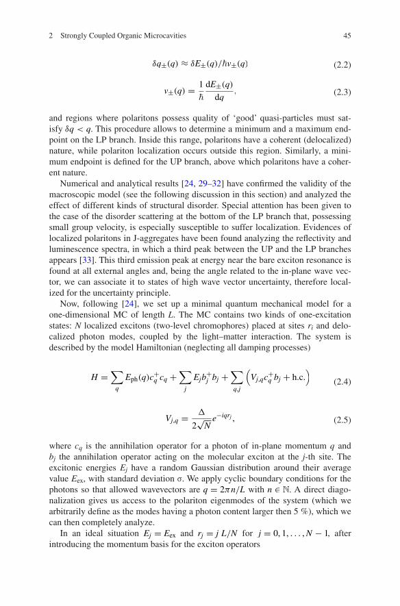
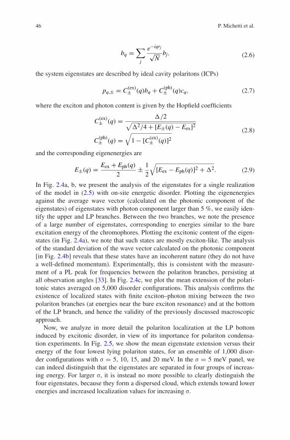
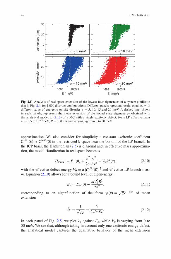
Now, we analyze in more detail the polariton localization at the LP bottom induced by excitonic disorder, in view of its importance for polariton condensa-tion experiments. In Fig. 2.5, we show the mean eigenstate extension versus their energy of the four lowest lying polariton states, for an ensemble of 1,000 disor-der configurations with σ = 5, 10, 15, and 20 meV. In the σ = 5 meV panel, we can indeed distinguish that the eigenstates are separated in four groups of increas-ing energy. For larger σ, it is instead no more possible to clearly distinguish the four eigenstates, because they form a dispersed cloud, which extends toward lower energies and increased localization values for increasing σ.
(2.6)bq =∑
j
e−iqrj
√N
bj,
(2.7)pq,± = C(ex)± (q)bq + C
(ph)± (q)cq,
(2.8)C(ex)± (q) =
�/2√
�2/4+ [E±(q)− Eex]2
C(ph)± (q) =
√
1− [C(ex)± (q)]2
(2.9)E±(q) =Eex + Eph(q)
2±
1
2
√
[Eex − Eph(q)]2 +�2.

472 Strongly Coupled Organic Microcavities
In order to better understand the mechanism that rules the localization of the lowest energy state, we now build a simplified analytical model for the LP bottom state in presence of a single exciton defect. Let us consider a model Hamiltonian (2.5), where all chromophores have the same excitation energy Eex with the excep-tion of a single defect in the origin of the real space, with the excitonic poten-tial energy is given by Eex − σRδ(x), with R the nearest neighbor distance being. We work on the reciprocal ICP space [span by (2.7)] near the bottom of the LP branch, for which the dispersion curve can be well captured by an effective mass
Fig. 2.4 Analysis of the eigenstates of a system of N = 1,000 chromophores of average on-site energy Eex = 1, 850meV and standard deviation σ = 20meV in a 1D MC of length L = 10−6 m realizing a Rabi splitting � = 120meV.a Color plot of the excitonic fraction of each eigenstates plotted against the average wave vector calculated on its the photonic part. b Standard deviation on the average wave vector calculated on the photonic part of the eigenstates. c Mean extension of the (polariton-like) eigenstates having photonic fraction >5 %, averaged on the spectral intervals and on an ensemble of 5,000 disorder configurations, for systems with σ = 5, 10 and 20 meV
1700 1800 1900 2000 2100
E (meV)
0
5
10
15
20
25
30
aver
age
exte
nsio
n (µ
m)
5 meV15 meV25 meV
LP UP
(a)
(b)
(c)
48 P. Michetti et al.
approximation. We also consider for simplicity a constant excitonic coefficient C(ex)− (k) ≈ C
(ex)− (0) in the restricted k-space near the bottom of the LP branch. In
the ICP basis, the Hamiltonian (2.5) is diagonal and, in effective mass approxima-tion, the model Hamiltonian in real space becomes
with the effective defect energy V0 = σ |C(ex)− (0)|2 and effective LP branch mass
m. Equation (2.10) allows for a bound level of eigenenergy
corresponding to an eigenfunction of the form ψ(x) = √χe−χ |x| of mean
extension
In each panel of Fig. 2.5, we plot �b against Eb, while V0 is varying from 0 to 50 meV. We see that, although taking in account only one excitonic energy defect, the analytical model captures the qualitative behavior of the mean extension
(2.10)Hmodel = E−(0)+�2
2m
d2
dx2− V0Rδ(x),
(2.11)Eb = E−(0)−mV2
0R2
2�2,
(2.12)�b =1√2χ
=�
2√mEb
,
0
10
20
30
exte
nsio
n (µ
m)
1663 1663,5
E (meV)
0
10
20
exte
nsio
n (µ
m)
1663 1663,5
E (meV)
σ = 5 meV
σ = 15 meV
σ = 10 meV
σ = 20 meV
Fig. 2.5 Analysis of real space extension of the lowest four eigenstates of a system similar to that in Fig. 2.4, for 1,000 disorder configurations. Different panels represent results obtained with different value of energetic on-site disorder σ = 5, 10, 15 and 20 meV. A dashed line, shown in each panels, represents the mean extension of the bound state eigenenergy obtained with the analytical model in (2.10) of a MC with a single excitonic defect, for a LP effective mass m = 0.5× 10⁻⁵meV, R = 100 nm and varying V0 from 0 to 50 meV
492 Strongly Coupled Organic Microcavities
with increasing disorder obtained from the numerical analysis. With diminishing energy, we can see an initial rapid decrease of the localization length (because the LP bottom has relatively flat dispersion curve), after a certain degree of localiza-tion, the Fourier components needed in order to further localize the wave function become higher in energy, therefore a further decrease of the localization length requires larger excitonic defects.
As a conclusion of this section, disorder in organic MCs leads to the coexist-ence of delocalized polariton states with localized ones, distributed in different spectral regions. Localization of strongly coupled states is expected at the LP bot-tom and near the bare exciton energy. From these two kind of polaritons, com-pletely different behaviors also from the point of view of their time evolutions properties have been predicted [31, 32], with delocalized polaritons featuring a ballistic motion and localized polaritons being instead diffusive.
2.2.2 Relaxation Dynamics
A complete microscopical analysis of the excitation dynamics of a strongly cou-pled MC should ideally start from a model describing the bare optically active material, and as a second step, this model should be refined for the strong-cou-pling limit. However, this procedure is difficult in organic MCs where, often, models describing the excitation dynamics in the bare materials are not known or very complex, or do not have a broad range of validity, even in the same class of materials. For this reason, the model developed for describing the full excitation dynamics of J-aggregate MCs in linear regimes [25, 34], which is directly derived as an extension of the Frenkel exciton model of the uncoupled material, assumes also a conceptual importance. This is made possible by the simple description of the bare J-aggregate film as an ensemble of one-dimensional Frenkel exciton systems [23, 35–37] and recurring to a phenomenological ansatz for the polariton wave function [25].
A linear J-aggregate can be considered as a chain composed of Nd monomers (dye molecules) described by the following Frenkel exciton Hamiltonian [23, 35]
The bi is the monomer exciton operator, and Ei = εi + Daggi is the sum of the bare
energy of the monomer excited state and energy shift due to the interaction of the ith excited molecule with the other molecules and the host medium in their ground states. The exciton transfer term is given by Vi,j = −J/|i − j|3, where J > 0 is the nearest neighbor coupling strength. When the molecules are put together, the inter-actions among them give rise to excitation transfer with the formation of delocal-ized Frenkel excitons (having a 1D energy dispersion curve called J-band) and
(2.13)H =Nd∑
i
Eib†i bi +
Nd∑
i �=j
Vi,j(b†i bj + b
†j bi)

50 P. Michetti et al.
thus to the superradiance phenomena. On the other hand, the presence of diagonal disorder is introduced as a Gaussian stochastic fluctuation of the monomer ener-gies; it brings about the fragmentation of the excitons in localized structures on the aggregate chain, especially in the spectral region at the bottom of J-band, with the consequence of inhomogeneous broadening. The diagonal disorder standard devia-tion is σ = σJ, where σ is used as a parameter of the disorder strength. The eigen-states are found by direct diagonalization of the Frenkel exciton Hamiltonian and are described by the following operators:
where cαi is the coefficient of the αth exciton on the ith molecule. The OS of each state is proportional to:
with ∑
α Fα = Nd, with the molecules of equal dipole transition, and with wave-length much greater than the aggregate dimension. In Fig. 2.6, we show the DOS and the OS for state for an ensemble of aggregates with disorder parameter σ = 0.54 and J = 75 meV, averaged over specific spectral intervals. Almost the whole OS of the film is concentrated among the superradiant excitons in a spectral region at the bottom of the J-band.
The Frenkel exciton model for the J-aggregates is then put into contact with a thermal bath that provides a mean for the thermalization of excitations [35–37]. The linear exciton–vibration coupling, treated with the Fermi golden rule, leads to the definition of scattering rates between initial and final excitonic states mediated by the emission/absorption of a vibrational quantum. For a continuous spectrum of vibrations, scattering rates have the following form [35–37]
(2.14)B†α =
∑
i
c(α)i b
†i
(2.15)Fα =
∣
∣
∣
∣
∣
∑
i
c(α)i
∣
∣
∣
∣
∣
2
Fig. 2.6 The DOS of the J-band dispersion (black) for an ensemble of J-aggregate with σ = 0.54 and the corresponding oscillator strength (red). The oscillator strength (OS) is accumulated in the states at the bottom of the J-band and inhomogeneously broadened by static disorder
512 Strongly Coupled Organic Microcavities
while for discrete optical vibrations we obtain
where i = (I ,α), with I running on different aggregates in the film and α on dif-ferent Frenkel excitons of the same aggregate, �E = Eα′ − Eα, Θ is the step func-tion, NE is the Bose-Einstein occupation factor of the states of the vibrational bath, W0 = 2πξJ/�, with ξ and p are parameters that describe the strength and spectral shape of the exciton scattering with vibrations [36, 37]. The overlap factor Ξi,i′ is defined as
The homogeneous linewidth of the states is due to the radiative lifetime and to the temperature-dependent dephasing processes that are dominated by the exciton-phonon scattering [37]. Each exciton state is broadened as a Lorentzian lineshape around the bare energy Eα:
with the energy uncertainty given by
We can now describe the excitation dynamics of a J-aggregate film, through the definition of rate equations for the Frenkel excitons in the low excitation density approximation
where we have added the radiative decay rate γα which, for excitons, is given by γα = Fαγ0, where γ0 is the spontaneous emission of the dye monomer, typically 0.3 ns−1. We also add a pump term Pα on the upper energy tail of the exciton DOS.
This model can be extended to a strongly coupled J-aggregate MC through the introduction of a model polariton wave function, for which we formulate the fol-lowing ansatz
(2.16)Wi′,i = W0�i,i′ × (N|�E| +�(�E))
(
|�E|J
)p
,
(2.17)Wi′,i =2πE2
υib
�Ξi,i′ × (N|�E| +Θ(�E))δ(|�E| − Evib),
(2.18)Ξi,i′ = δI ,I ′
Nd∑
n=1
∣
∣
∣c(α)i c
(α′)i
∣
∣
∣
2.
(2.19)gα(E) =�Eα/π
(Eα − E)2 + (�Eα)2
(2.20)�Eα = �(∑
α′Wα′,α + γα)
(2.21)nα =∑
α′(Wα,α′nα′ −Wα′,αnα)− γαnα + Pα
(2.22)p+k,± = C(ph)± (k)c+k +
C(ex)± (k)√
Nagg
Nagg∑
I
Nd∑
α
φ(k)α,I B
+α,I

52 P. Michetti et al.
where C(ex)k ,C
(ph)k
are given by (2.8) and |φ(k)α,I | =
√Fα/Nd . This allows us to cal-
culate the coupling of polariton states with the thermal bath acting on the molec-ular Frenkel excitons of the aggregates and to derive the form of the scattering rates between all states of the system [25, 34, 38]. The scattering rates have the same form as (2.16) and (2.17), where now i, i′ runs on the excitonic states of the film n′ = (α, I), i.e., the αth exciton of the Ith aggregate, and on the delocal-ized polaritons k = (±, q), ± polariton branch and momentum q. However, dif-ferent overlap factors Ξi,i′ have to be employed for different processes (we refer to the original literature for the full details [25]). We only mention that overlap factors involving polaritons (Ξk,n′, Ξn′,k, and Ξk′,k), are suppressed by a factor Nagg, being the number of sites on which the polariton state is delocalized. This is due to the contrast between extended polariton states and the localized nature of vibrations.
In addition to the phonon-mediated scattering, we have also considered a radia-tive pumping rate from exciton to polariton [25, 38] in the following form:
Such radiative scattering is proportional to the exciton OS and the transfer matches energy conservation, while the normalization is chosen to obtain a net exciton radiative decay toward polaritons of βrad times the spontaneous emission (γα). The broadening gα is given by (2.19), calculated for the cavity system. This process usually accounts for the presence of a residual weakly coupled excitons in the sys-tem, but can also more generally describe the presence of emitting weakly coupled excitons of different nature as it happens in [39], where the authors have engi-neered a MC with an exciton reservoir (ER) of weakly coupled molecules (chemi-cally different from the molecules giving the strong coupling) resonant with the LP branch bottom. The radiative process described by (2.23) is exploited to effi-ciently populate of the LP bottom from this ER (which is non-resonantly pumped).
To deal with the 2D MC, we assume isotropic conditions in which the polari-ton population depends only on the modulus of the wave vector. We describe the dynamics of excitation relaxation by means of a rate equation for the population of state fi(t):
where the indices i, i′ run over all the spectrum of excitations and can refers to both polariton (k, upper or lower) or localized excitons (n). The damping rate due to the escape through the cavity mirrors is given by Γk = |C(ph)
± (q)|2/τp. The typi-cal photon lifetime is about τp = 35 fs, corresponding to a photon linewidth of the order of 30 meV. P is the pumping rate that we apply as for the aggregate film to the high energy tail of the J-band. For the details of numerical implementation and solution of (2.24) for a J-aggregate MC with a sensible ensemble average over the J-aggregate disorder configurations, see [25].
(2.23)W radk,α = βradγα
|C(ph)k |2gα(Ek)
∑
k′ |C(ph)
k′ |2gα(Ek′).
(2.24)fi(t) = −Γifi(t)+∑
i′(Wi,i′ fi′(t)−Wi′,ifi(t))+ Pi
532 Strongly Coupled Organic Microcavities
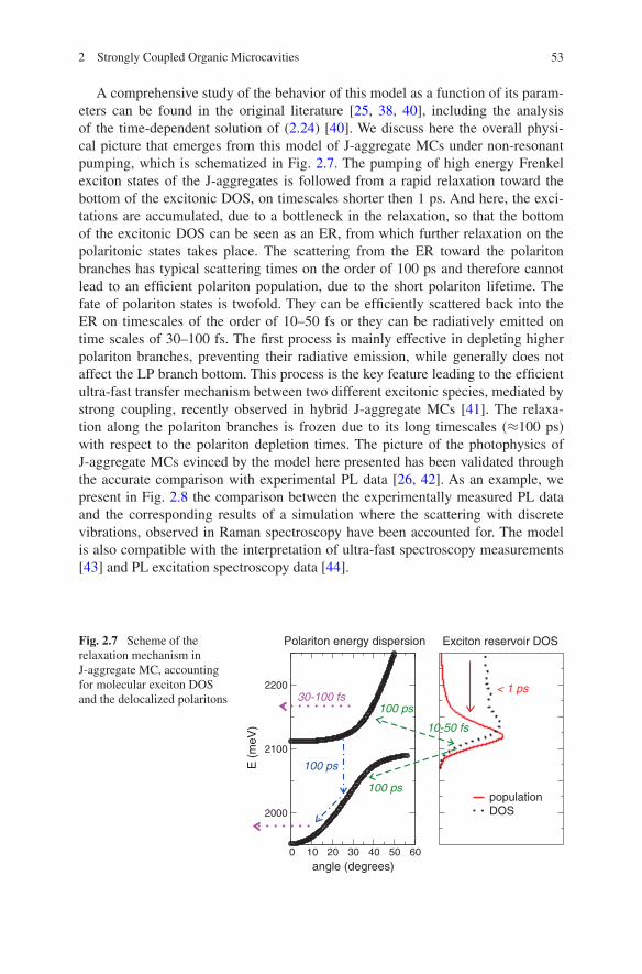
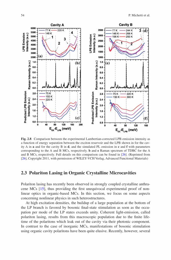
A comprehensive study of the behavior of this model as a function of its param-eters can be found in the original literature [25, 38, 40], including the analysis of the time-dependent solution of (2.24) [40]. We discuss here the overall physi-cal picture that emerges from this model of J-aggregate MCs under non-resonant pumping, which is schematized in Fig. 2.7. The pumping of high energy Frenkel exciton states of the J-aggregates is followed from a rapid relaxation toward the bottom of the excitonic DOS, on timescales shorter then 1 ps. And here, the exci-tations are accumulated, due to a bottleneck in the relaxation, so that the bottom of the excitonic DOS can be seen as an ER, from which further relaxation on the polaritonic states takes place. The scattering from the ER toward the polariton branches has typical scattering times on the order of 100 ps and therefore cannot lead to an efficient polariton population, due to the short polariton lifetime. The fate of polariton states is twofold. They can be efficiently scattered back into the ER on timescales of the order of 10–50 fs or they can be radiatively emitted on time scales of 30–100 fs. The first process is mainly effective in depleting higher polariton branches, preventing their radiative emission, while generally does not affect the LP branch bottom. This process is the key feature leading to the efficient ultra-fast transfer mechanism between two different excitonic species, mediated by strong coupling, recently observed in hybrid J-aggregate MCs [41]. The relaxa-tion along the polariton branches is frozen due to its long timescales (≈100 ps) with respect to the polariton depletion times. The picture of the photophysics of J-aggregate MCs evinced by the model here presented has been validated through the accurate comparison with experimental PL data [26, 42]. As an example, we present in Fig. 2.8 the comparison between the experimentally measured PL data and the corresponding results of a simulation where the scattering with discrete vibrations, observed in Raman spectroscopy have been accounted for. The model is also compatible with the interpretation of ultra-fast spectroscopy measurements [43] and PL excitation spectroscopy data [44].
Fig. 2.7 Scheme of the relaxation mechanism in J-aggregate MC, accounting for molecular exciton DOS and the delocalized polaritons
0 10 20 30 40 50 60angle (degrees)
2000
2100
2200
E (
meV
)
Polariton energy dispersion
populationDOS
Exciton reservoir DOS
< 1 ps30-100 fs
100 ps
10-50 fs
100 ps
100 ps
54 P. Michetti et al.
2.3 Polariton Lasing in Organic Crystalline Microcavities
Polariton lasing has recently been observed in strongly coupled crystalline anthra-cene MCs [15], thus providing the first unequivocal experimental proof of non-linear optics in organic-based MCs. In this section, we focus on some aspects concerning nonlinear physics in such heterostructures.
At high excitation densities, the buildup of a large population at the bottom of the LP branch is favored by bosonic final-state stimulation as soon as the occu-pation per mode of the LP states exceeds unity. Coherent light-emission, called polariton lasing, results from this macroscopic population due to the finite life-time of the polaritons which leak out of the cavity via their photonic component. In contrast to the case of inorganic MCs, manifestations of bosonic stimulation using organic cavity polaritons have been quite elusive. Recently, however, several
Fig. 2.8 Comparison between the experimental Lambertian-corrected LPB emission intensity as a function of energy separation between the exciton reservoir and the LPB shown in for the cav-ity A in a and for the cavity B in d, and the simulated PL emission in c and f with parameters corresponding to the A and B MCs, respectively. b and e Raman spectrum of TDBC for the A and B MCs, respectively. Full details on this comparison can be found in [26]. (Reprinted from [26], Copyright 2011, with permission of WILEY-VCH Verlag, Advanced Functional Materials)
552 Strongly Coupled Organic Microcavities
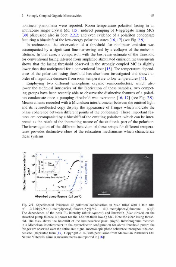
nonlinear phenomena were reported: Room temperature polariton lasing in an anthracene single crystal MC [15], indirect pumping of J-aggregate lasing MCs [39] (discussed also in Sect. 2.2.2) and even evidence of a polariton condensate featuring a blueshift of the low-energy polariton states [16, 17] (see Fig. 2.9).
In anthracene, the observation of a threshold for nonlinear emission was accompanied by a significant line narrowing and by a collapse of the emission lifetime. In that case, a comparison with the best-case estimate of the threshold for conventional lasing inferred from amplified stimulated emission measurements shows that the lasing threshold observed in the strongly coupled MC is slightly lower than that anticipated for a conventional laser [15]. The temperature depend-ence of the polariton lasing threshold has also been investigated and shows an order of magnitude decrease from room temperature to low temperatures [45].
Employing two different amorphous organic semiconductors, which also lower the technical intricacies of the fabrication of these samples, two compet-ing groups have been recently able to observe the distinctive features of a polari-ton condensate once a pumping threshold was overcome [16, 17] (see Fig. 2.9). Measurements recorded with a Michelson interferometer between the emitted light and its retroreflected copy display the appearance of fringes which indicate the phase coherence between different points of the condensate. These important fea-tures are accompanied by a blueshift of the emitting polariton, which can be inter-preted as the result of the interacting nature of the excitonic part of the polariton. The investigation of the different behaviors of these setups for different tempera-tures provides distinctive clues of the relaxation mechanisms which characterize these systems.
Fig. 2.9 Experimental evidences of polariton condensation in MCs filled with a thin film of 2,7-bis[9,9-di(4-methylphenyl)-fluoren-2-yl]-9,9- di(4-methylphenyl)fluorene. (Left) The dependence of the peak PL intensity (black squares) and linewidth (blue circles) on the absorbed pump fluence is shown for the 120-nm-thick low-Q MC. Note the clear lasing thresh-old. The inset shows the blueshift of the luminescence peak. (Right) Interferograms recorded in a Michelson interferometer in the retroreflector configuration for above-threshold pump; the fringes are observed over the entire area signal macroscopic phase coherence throughout the con-densate. (Reprinted from [17]. Copyright 2014, with permission from Macmillan Publishers Ltd: Nature Materials. Similar measurements are reported in [16])
56 P. Michetti et al.
These remarkable experiments are triggering new theoretical work. In [46], the authors investigate the condensation physics of polaritons where the matter exci-tations are vibrationally dressed, a typical situation in organic materials. Using mean-field methods, the authors argue on the appearance of sequences of normal-superradiant-normal phases as temperature is decreased. Moreover, for sufficiently strong vibrational couplings, the phase transition can become first order.
The possibility of observing nonlinear phenomena in MCs embedding organic amorphous solids, whose fabrication is easier with respect to inorganic and organic crystals, will surely trigger a boost in the field of polaritonics. Among the several fields where we expect important developments in the next future, we men-tion here the long-standing goal of realizing an electrically pumped organic laser: The possibility of overcoming the encountered difficulties via the strong-coupling physics is currently renewing the race [47].
In this section, we focus on the lasing measurements in anthracene MCs and present a simple model which describes the onset of the lasing threshold based on a master equation. The mechanism governing the buildup of the polariton population—namely bosonic-stimulated scattering from the ER via a vibronically assisted process—is characterized and its efficiency calculated on the basis of a microscopic theory [48–50].
2.3.1 Two-level Model for Polariton Lasing
In this section, we model the dynamics of the lasing process using a minimal rate–equation approach; we obtain an estimate for the typical timescale of the mecha-nism which selectively transfers excitations from the reservoir to the bottom of the polariton branch, without any assumptions on its microscopic nature.
2.3.1.1 The Master Equation
The anthracene crystal has two molecules per unit cell and strongly anisotropic optical properties [14, 51]. Excitations in this material are well described within the Frenkel exciton framework, which is based on the intramolecular promotion of an electron from the highest occupied molecular orbital to the lowest unoc-cupied one. Because of molecular dipole–dipole interaction, the excitation can propagate, resulting in two orthogonal transition dipole moments, µa,b, directed along the in-plane a and b axes. When a thin anthracene crystal is placed between two mirrors, light couples to both a- and b-polarized excitons and creates two orthogonally polarized LP branches. Measurements are usually reported for light polarized along a and b [15, 51]: In these cases, the p and s in-cavity light polari-zations separately couple to the dipole moments µa,b and no mixing effect is present.

572 Strongly Coupled Organic Microcavities
We focus only on b-polarized excitons [14], i.e., those with largest OS, for which lasing has been reported [15] and neglect other polaritonic and exci-tonic states. The initial relaxation of the pump excitations is also neglected, and the presence of an effective excitonic reservoir at a fixed energy independent on the cavity properties is considered [25]. We note that the experimental PL from anthracene MCs shows always a clear maximum at energy ~2.94 eV regardless of the cavity thickness [15, 52], and indeed lasing has been achieved in a cavity where the minimum of the LP is exactly at 2.95 eV. This is a signature that the microscopic dynamics resulting in the lasing phenomenon is that of a two-level process rather than that of the well-known polariton bottleneck. We thus develop a two-level master equation for ve(t) and vp(t), the surface density of reservoir exci-tons and of lasing polaritons located near k = 0, respectively.
We denote with A0 the subregion of the Brillouin zone located around k = 0 which is occupied by the lasing polaritons. Because states at the bot-tom of the LP branch do not have a well-defined wave vector k, we consider all of the localized wave packets with energy ∼ELP(k = 0) as equally contrib-uting to the lasing process. Npol is the number of such polaritonic states, while Nexc is the number of excitonic states. The polariton and exciton decay rates are Γp = |C(ex)|2/τe + |C(ph)|2/τp and Γe = 1/τe, respectively, where τp(τe) is the bare photon (exciton) lifetime and C(ph)
(
C(ex))
is the photonic (excitonic) Hopfield coefficient for the lasing polaritons.
The parameter Ze is the decay rate via other channels, such as phonons, LPs outside the A0 region and leaky modes, whereas bimolecular quenching pro-cesses are treated separately, with a rate γ ′. A standard pump term proportional to P′(t) is included; in order to take into account possible saturation effects the term (1− νe/νe) has been considered (νe = Nexc/A is the surface density of excitonic states and A is the area of the sample).
The rate of resonant excitation transfer from the reservoir to the lasing polari-tons is W ep. We retain the bosonic enhancement term (1+ νp/νp) responsible for lasing effects, where νp = Npol/A is the surface density of polaritonic states.
The master equation for ve(t) and vp(t), whose physics is sketched in Fig. 2.10, reads (see [50] for the full derivation and more comprehensive discussion):
Note that the resulting equations are completely analogous to those describing conventional lasing [53], with the important difference that the lasing state is a polariton and thus retains an excitonic component.
(2.25a)
νe =− Ŵeνe −Wepνe
(
1+νp
νp
)
− Zeνe − γ ′νe(
νe + |C(ex)|2νp)
+(
1−νe
νe
)
P′(t)
(2.25b)νp = −Γpνp +W epνe
(
1+νp
νp
)
− γ ′(
νe + |C(ex)|2νp)
|C(ex)|2νp

58 P. Michetti et al.
2.3.1.2 Parameters
We relate (2.25a) and (2.25b) to the experimental system in [15] using the follow-ing parameters.
Anthracene Crystal. The experimental MC embeds a crystal of anthracene with thickness Lz = 120 nm; the molecular density is ρ0 = 4.2× 1021cm−3: We ignore the monoclinic structure of the unit cell and instead estimate its linear size as a = (ρ0/2)
−1/3 = 7.8× 10⁻⁸cm, including the presence of two molecules per unit cell. The number of layers is estimated as N = Lz/a ≈ 153. The absorption maximum of the anthracene crystal is at energy E0 = 3.17 eV. The exciton meas-ured lifetime is of the order of τe ∼ 1− 3 ns and in the next simulations, we take the intermediate value τe = 2 ns. The contribution of Ze is neglected because it can be included into τe without any substantial difference as long as τe < 1/Ze, which can be safely assumed.
MC and Polaritons. If we assume homogeneous broadening, the cavity lifetime can be estimated from the polariton linewidth at k = 0, where it is mostly photon-like. Using this approach, we obtain a lower bound τp = 85 fs. An exact calculation assuming perfect interfaces for the mirrors results in an upper bound τp = 1 ps. We will estimate Wep corresponding to both extrema. The Hopfield coefficients of the LP branch are [51]: C(ph) = 0.92 and C(ex) = 0.39.
For small |k|, the A0 region has cylindrical symmetry [54–56]. Its radius, q0, can be estimated using ELP(q0)− ELP(k = 0) = Γ0/2, where Γ0 = 15meV is the linewidth of polaritons at k = 0 below threshold [15]; we obtain q0 = 2.2× 104 cm−1.
Pump. The pump density is: P′(t) = P′0 exp
[
−t2/(2σ 2t )]
(σt ∼ 64 fs), with P′0 = P0/(πr
20�ωpump) where r0 = 110 μm is the radius of the pump spot and
�ωpump = 3.45 eV is the energy of the pump photons. P0 can be derived from the
Pump P ′(t)
Efficienttransfer
Exciton
quenching γ′Bimolecular
decay Γe
Decay topolaritons
mechanism Wep
Lowerpolaritonbranch
reservoir, νeExciton
Ze
Lasingpolaritons,νp
Bimolecularquenching γ′
Luminescence Γp
Fig. 2.10 Sketch of the LP branch and of the physical processes and scattering mechanisms included in the master equation (2.1). (Reprinted from [50], Copyright 2013, with permission from American Physical Society)
592 Strongly Coupled Organic Microcavities
relation Etot =∫
P(t)dt =√2πP0σt, where Etot is the experimentally measured
total absorbed energy.Bimolecular Quenching Rate. To the best of our knowledge, there are no
measurements of the bimolecular quenching rate, γ ′, for 2D anthracene crystals. According to the standard theory for bimolecular quenching [14], γ3D = 8πRD, where R is the Förster radius of the exciton and sets the volume around the exci-ton in which annihilation happens, while D is the diffusion coefficient of exci-tons. Measurements for 3D anthracene crystals have yielded values of [14] γ3D = 10−8cm3s−1 and [14, 57] D ∼ 1− 10× 10−3cm2s−1. The corresponding diffusion length ℓ = (τeD)
1/2 ∼ 1− 3× 10⁻⁶ cm is smaller than Lz = 1.2× 10⁻⁵ and suggests that excitons can be treated as diffusing in a 3D environment. As a result, we initially fix γ ′ = γ3D/Lz = 7× 10⁻⁴ cm2s−1.
2.3.1.3 Results
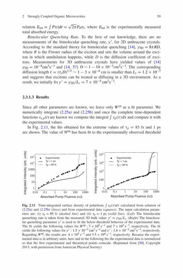
Since all other parameters are known, we leave only Wep as a fit parameter. We numerically integrate (2.25a) and (2.25b) and once the complete time-dependent functions νe,p(t) are known we compute the integral
∫
νp(τ )dτ and compare it with the experimental values.
In Fig. 2.11, the fits obtained for the extreme values of τp = 85 fs and 1 ps are shown. The value of Wep has been fit to the experimentally observed threshold
0.01 0.1 1 10 100 10001
10
100
1000
104
105
Absorbed Pump Fluence (nJ)
Inte
grat
ed In
tens
ity (
arb.
uni
ts)
Experimental= 1 ps
τpτp
= 85 fs
0.01 0.1 1 10 100 10001
100
104
106
108
Inte
grat
ed In
tens
ity (
arb.
uni
ts)
Absorbed Pump Fluence (nJ)
Experimental= 1 ps
τpτp
= 85 fs
Fig. 2.11 Time-integrated surface density of polaritons ∫
νp(τ )dτ calculated from solution of (2.25a) and (2.25b) (lines) and from experimental data (squares). The input calculation param-eters are: (i) τp = 85 fs (dashed line) and (ii) τp = 1 ps (solid line). (Left) The bimolecular quenching rate is taken from the measured 3D bulk value: γ ′ = γ3D/Lz. (Right) The bimolecu-lar quenching parameter γ ′ is used to fit the below-threshold behavior of the experimental data. The fit yields the following values for W ep : 7× 10⁵ s−1 and 7× 10⁵ s−1, respectively. The fit yields the following values for γ ′ : 1.5× 10⁻⁵ cm2 s−1 and γ ′ : 1.6× 10⁻⁵ cm2 s−1, respectively. Regarding W ep, the results are: 4× 10⁵ s−1 and 3.5× 10⁴ s−1, respectively. Because the experi-mental data is in arbitrary units, here and in the following fits the experimental data is normalized so that the first experimental and theoretical points coincide. (Reprinted from [50], Copyright 2013, with permission from American Physical Society)

60 P. Michetti et al.
value. In both cases, Wep is of the order 105 s−1. The agreement with the experi-ment is poor and it is apparent that the chosen value of γ ′ does not properly describe the transition between linear and sublinear region below threshold. Note that the exciton lifetime τe ∼ 2 ns is shorter than the reported bulk value [14] τe,bulk ∼ 10 ns; surface interactions or defects within the layers could explain this discrepancy. In this situation, the excitonic diffusion coefficient can be smaller, resulting in a reduced possibility for excitons to pairwise annihilate.
Because a fit of γ ′ which determines the onset of bimolecular quenching can be readily decoupled from that of Wep, both parameters are allowed to vary and the resulting fits are shown in Fig. 2.11. We obtain γ ′ ≈ 1.5× 10⁻⁵cm2s−1 indepen-dently of τp, as expected. Note that this value is two orders of magnitude smaller than γ3D/Lz. The resulting values for Wep are 4× 10⁵ s−1 and 3.5× 10⁴ s−1 for τp = 85 fs and 1 ps, respectively. Even if the scattering process acts on a sensi-bly longer timescale compared to the exciton and polariton lifetimes, it can lead to observable effects in presence of high excitonic densities. We can roughly esti-mate the surface density of excitons at threshold via Γpνp = W epνe(1+ νp/νp). Assuming that at threshold νp = νp, we obtain:
The density of excitations is thus extremely high, though not unrealistic. Moreover, this is consistent with what shown in Fig. 2.12, where at threshold, the peak exciton value is of few percents. Note that νe,th/νe does not depend on the value of q0, because both Wep and νp depend linearly on the size of the A0 region.
Note that even if the two fits yield very different values for Wep, the fit is not ill-conditioned. The fit of the below-threshold region depends only on two param-eters, τpW ep and γ ′ . It is our ignorance of τp, whose value can vary by more than one order of magnitude and still be compatible with the measurements, which propagates an uncertainty of one order of magnitude on Wep. In Sect. 2.3.2, we show a simple analytical model which corroborates this picture.
(2.26)νe,th
νe=
νp
νe
Γp
2Wep∼ 0.01
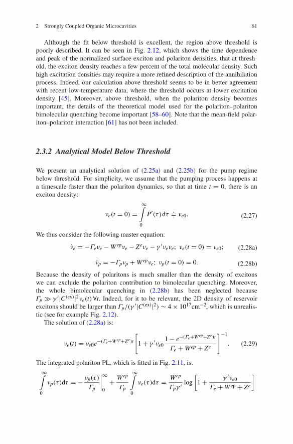
0.0 0.5 1.0 1.5 2.010 510 4
0.0010.010.1
110
Time ns0.01 0.1 1 10 100 1000
104106108
101010121014
Absorbed Pump Fluence nJ
Surf
ace
Den
sity
cm2
Fig. 2.12 (Left) Time dependence of the normalized surface density of excitons νe(t)/νe and of polaritons νp(t)/νp below threshold (≈ 0.047, dotted line and solid line, respectively) and at threshold (Etot = 150 nJ, dashed line and dashed-dotted line) plotted for −1 fs. Note that this time dependence is in good agreement with that reported in [15]. (Right) Maximal population density of excitons maxt νe(t) (squares) and of lasing photons maxt νp(t) (circles). See Fig. 2.11 for the parameters; τp = 85 fs (Reprinted from [50], Copyright 2013, with permission from American Physical Society)
612 Strongly Coupled Organic Microcavities
Although the fit below threshold is excellent, the region above threshold is poorly described. It can be seen in Fig. 2.12, which shows the time dependence and peak of the normalized surface exciton and polariton densities, that at thresh-old, the exciton density reaches a few percent of the total molecular density. Such high excitation densities may require a more refined description of the annihilation process. Indeed, our calculation above threshold seems to be in better agreement with recent low-temperature data, where the threshold occurs at lower excitation density [45]. Moreover, above threshold, when the polariton density becomes important, the details of the theoretical model used for the polariton–polariton bimolecular quenching become important [58–60]. Note that the mean-field polar-iton–polariton interaction [61] has not been included.
2.3.2 Analytical Model Below Threshold
We present an analytical solution of (2.25a) and (2.25b) for the pump regime below threshold. For simplicity, we assume that the pumping process happens at a timescale faster than the polariton dynamics, so that at time t = 0, there is an exciton density:
We thus consider the following master equation:
Because the density of polaritons is much smaller than the density of excitons we can exclude the polariton contribution to bimolecular quenching. Moreover, the whole bimolecular quenching in (2.28b) has been neglected because Γp ≫ γ ′|C(ex)|2νe(t) ∀t. Indeed, for it to be relevant, the 2D density of reservoir excitons should be larger than Γp/(γ
′|C(ex)|2) ∼ 4× 1017cm−2, which is unrealis-tic (see for example Fig. 2.12).
The solution of (2.28a) is:
The integrated polariton PL, which is fitted in Fig. 2.11, is:
(2.27)νe(t = 0) =∞∫
0
P′(τ )dτ.=· νe0.
(2.28a)νe = −Γeνe −Wepνe − Zeνe − γ ′νeνe; νe(t = 0) = νe0;
(2.28b)νp = −Γpνp +Wepνe; νp(t = 0) = 0.
(2.29)νe(t) = νe0e−(Γe+Wep+Ze)t
[
1+ γ ′νe01− e−(Γe+Wep+Ze)t
Γe +Wep + Ze
]−1
.
∞∫
0
νp(τ )dτ = −νp(τ )
Γp
∣
∣
∣
∣
∞
0
+Wep
Γp
∞∫
0
νe(τ )dτ =Wep
Γpγ ′ log
[
1+γ ′νe0
Γe +W ep + Ze
]

62 P. Michetti et al.
Let us now observe that in our system Γe ≫ W ep, Ze and that the experimen-tal data are proportional to
∫
νpdτ via an unknown constant, which in the fits in Sect. 2.3.1 is chosen so that the experimental and theoretical points for the lowest pump fluence coincide. This makes the fit of the below-threshold region dependent only on γ ′ and independent on Wep and τp.
2.3.3 The Scattering Mechanism
In this section, we focus on the microscopic origin of the excitation transfer of Sect. 2.3.1 and propose as the relevant scattering mechanism the radiative recom-bination of a molecular exciton assisted by the emission of a vibrational quantum of the electronic ground state. We show that the resulting scattering rate is in good agreement with that obtained in the previous section; we also consider an alterna-tive and possibly coexisting model based on the non-radiative emission of an opti-cal phonon [62].
2.3.3.1 Radiative Transition
The absorption and PL spectra of anthracene show several vibronic resonances [63]. The resonances observed in absorption correspond to the molecular vibra-tions of the first electronically excited state, and those in PL to the vibrations of the electronic ground state [14]. Strong light-matter coupling has only been demonstrated for the former [64], since the fraction of vibrationally excited ground-state molecules is negligible at room temperature. However, as shown schematically in Fig. 2.13, the transitions responsible for the vibronic struc-ture in PL result in the scattering of excitons to lower energy polaritons, where
Final stateProcess
Scattering
emissionradiative
Electronicexcitedstates
Electronicgroundstates
Initial stateElectronicexcitedstates
statesgroundElectronic
Molecularstates
Molecularstates (photon)
Polariton
assistedVibronically
Fig. 2.13 Sketch of the radiative microscopic mechanism responsible for the efficient excitation transfer in the Franck–Condon approximation. (Reprinted from [50], Copyright 2013, with per-mission from American Physical Society)
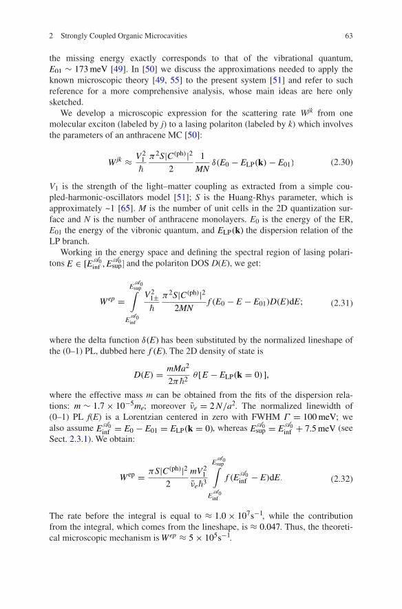
632 Strongly Coupled Organic Microcavities
the missing energy exactly corresponds to that of the vibrational quantum, E01 ∼ 173meV [49]. In [50] we discuss the approximations needed to apply the known microscopic theory [49, 55] to the present system [51] and refer to such reference for a more comprehensive analysis, whose main ideas are here only sketched.
We develop a microscopic expression for the scattering rate Wjk from one molecular exciton (labeled by j) to a lasing polariton (labeled by k) which involves the parameters of an anthracene MC [50]:
V1 is the strength of the light–matter coupling as extracted from a simple cou-pled-harmonic-oscillators model [51]; S is the Huang-Rhys parameter, which is approximately ~1 [65]. M is the number of unit cells in the 2D quantization sur-face and N is the number of anthracene monolayers. E0 is the energy of the ER, E01 the energy of the vibronic quantum, and ELP(k) the dispersion relation of the LP branch.
Working in the energy space and defining the spectral region of lasing polari-tons E ∈ [EA0
inf ,EA0sup] and the polariton DOS D(E), we get:
where the delta function δ(E) has been substituted by the normalized lineshape of the (0–1) PL, dubbed here f (E). The 2D density of state is
where the effective mass m can be obtained from the fits of the dispersion rela-tions: m ∼ 1.7× 10⁻⁵me; moreover νe = 2N/a2. The normalized linewidth of (0–1) PL f(E) is a Lorentzian centered in zero with FWHM Γ = 100meV; we also assume EA0
inf = E0 − E01 = ELP(k = 0), whereas EA0sup = E
A0
inf + 7.5meV (see Sect. 2.3.1). We obtain:
The rate before the integral is equal to ≈ 1.0× 10⁷s−1, while the contribution from the integral, which comes from the lineshape, is ≈ 0.047. Thus, the theoreti-cal microscopic mechanism is Wep ≈ 5× 10⁵s−1.
(2.30)Wjk ≈V21
�
π2S|C(ph)|2
2
1
MNδ(E0 − ELP(k)− E01)
(2.31)Wep =EA0sup∫
EA0inf
V21±�
π2S|C(ph)|2
2MNf (E0 − E − E01)D(E)dE;
D(E) =mMa2
2π�2θ [E − ELP(k = 0)],
(2.32)W ep =πS|C(ph)|2
2
mV21
νe�3
EA0sup∫
EA0inf
f (EA0
inf − E)dE.

64 P. Michetti et al.
Because the theoretical model neglects effects which can possibly lower the efficiency of the resonant scattering, we consider our estimate to be in good agree-ment with the values estimated from data in Sect. 2.3.1.
2.3.3.2 Non-radiative Transition
We now consider an alternative and possibly coexisting relaxation channel, which is non-radiative [62]. An exciton is scattered from the reservoir to one polariton state by the emission of a molecular vibration of the electronic excited state. This is due to the intramolecular exciton–phonon coupling [4, 66] which has been dem-onstrated to play a key role in the modeling of the PL of J-aggregates MCs [26, 38] (see also Sect. 2.2.2).
Note that in this case, the considered phonon belongs to the electronic excited state, whereas in the radiative case, it was related to the electronic ground state. Moreover, the resulting scattering element Wek includes the excitonic content of the out coming polariton, whereas (2.32) is weighted by the photonic Hopfield coefficient. The scattering rate from one molecular exciton (labeled by j) to one lasing polariton (labeled by k) is given by [62]:
where √S ∼ 1 is the strength of the exciton–phonon coupling [65] and E11 is the
energy quantum of a vibration of the excited state. Even if the Franck–Condon model which we are using prescribes E11 = E01, this is not necessarily true in gen-eral. The factor |C(ex)|2/(2NM) is the Hopfield coefficient for the exciton of the molecule j relative to the polariton k [62].
The comparison of (2.33) with (2.30) for the radiative case shows that the ratio of the two processes is:
Since both V1 and E11 are of the same order of magnitude, 100 meV, the efficiency ratio mainly depends on the Hopfield coefficients of the bottom polaritons. Thus, as in our case |C(ph)|2/|C(ex)|2 ≈ 5, we expect the radiative mechanism to be the main origin of the excitation transfer which results in lasing, even if to understand the impor-tance of the non-radiative transfer a more detailed analysis is necessary. An experimen-tal analysis exploring several organic crystals would thus be of the greatest interest.
2.3.4 The Effect of Temperature
Reported data for anthracene MCs show a reduction of the lasing threshold of slightly less than an order of magnitude once temperature is lowered from 300 to
(2.33)Wjk =2π
�SE2
11
|C(e)|2
2NMδ(E0 − ELP(k)− E11)
(2.34)W
jkRAD
WjkNON−RAD
=πV2
1
2E211
·|C(ph)|2
|C(ex)|2.
652 Strongly Coupled Organic Microcavities
12 K [45]. In this section, we discuss temperature effects within the framework of the developed model and the related consequences on the lasing properties.
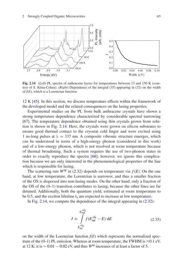
Experimental studies on the PL from bulk anthracene crystals have shown a strong temperature dependence characterized by considerable spectral narrowing [67]. The temperature dependence obtained using thin crystals grown from solu-tion is shown in Fig. 2.14. Here, the crystals were grown on silicon substrates to ensure good thermal contact to the cryostat cold finger and were excited using 1 ns-long pulses at λ = 337 nm. A composite vibronic structure emerges, which can be understood in terms of a high-energy phonon (considered in this work) and of a low-energy phonon, which is not resolved at room temperature because of thermal broadening. Such a system requires the use of two-phonon states in order to exactly reproduce the spectra [68]; however, we ignore this complica-tion because we are only interested in the phenomenological properties of the line which is responsible for lasing.
The scattering rate W ep in (2.32) depends on temperature via f (E). On the one hand, at low temperature, the Lorentzian is narrower, and thus a smaller fraction of the OS is dispersed into non-lasing modes. On the other hand, only a fraction of the OS of the (0–1) transition contributes to lasing, because the other lines are far detuned. Additionally, both the quantum yield, estimated at room temperature to be 0.5, and the exciton lifetime τe are expected to increase at low temperature.
In Fig. 2.14, we compute the dependence of the integral appearing in (2.32):
on the width of the Lorentzian function f(E) which represents the normalized spec-trum of the (0–1) PL emission. Whereas at room temperature, the FWHM is ≈0.1 eV, at 12 K, it is ∼ 0.01− 0.02 eV, and thus Wep increases of at least a factor of 5.
(2.35)I.=·
EA0sup∫
EA0inf
f (EA0
inf − E) dE
0.00 0.02 0.04 0.06 0.08 0.100.0
0.1
0.2
0.3
0.4
0.5
Width eV
I
Fig. 2.14 (Left) PL spectra of anthracene layers for temperatures between 13 and 150 K (cour-tesy of S. Kéna-Cohen). (Right) Dependence of the integral (35) appearing in (32) on the width of f(E), which is a Lorentzian function

66 P. Michetti et al.
Roughly speaking, the observed thermal reduction of the threshold is of less than one order of magnitude [45], and thus similar to the numbers of our esti-mates. This points out a possible connection between the temperature depend-ence of the laser threshold and of the PL of anthracene crystals. A more systematic analysis, both theoretical and experimental, goes beyond the scope of this work and will be the focus of future investigations. As long as the thermal linewidth nar-rowing is considered, we observe that when the radiative transition is not perfectly resonant with the lasing , it could even result in the opposite effect.
For the sake of completeness, in [50], we also include the thermal population of the vibrations of the molecular ground state in the master (2.25a) and demonstrate that it can be safely neglected.
Concluding, we have presented a minimal model to describe the polariton las-ing physics observed in crystalline anthracene MCs. Only the essential features of the physical processes involved have been included: The incoherently pumped ER, the vibronically assisted radiative scattering from the reservoir to the bottom of the LP branch, the onset of bosonic stimulation and the buildup of the polariton population with increasing pump intensity, the polariton losses through the mir-rors, and bimolecular quenching processes. All the relevant material parameters, except from the bimolecular quenching rate, have been determined independently from the experimental data on the pump dependence of the polariton emission. In particular, the efficiency of the scattering mechanism here considered—which takes into account the prominent role of vibronic replicas in the photophysics of anthracene MCs—has been calculated microscopically. The numerical simulations obtained are in good agreement with the data and describe well the onset of the nonlinear threshold for polariton lasing.
Acknowledgements We would like to thank for many insightful discussions V.M. Agranovich, S. Kéna-Cohen, D. Lidzey, R. Mahrt, L. Silvestri. We acknowledge financial support from the European FP7 ICARUS program (Grant Agreement No. 237900), the Regione Toscana POR FSE 2007-2013, and the Deutsche Forschungsgemeinschaft.
References
1. M.S. Skolnick, T.A. Fisher, D.M. Whittaker, Semicond. Sci. Technol. 13, 645 (1998) 2. A. Kavokin, J.J. Baumberg, G. Malpuech, F.P. Laussy, Microcavities (Oxford University
Press, Oxford, 2007) 3. I. Carusotto, C. Ciuti, Rev. Mod. Phys. 85, 299 (2013) 4. V.M. Agranovich, Excitations in Organic Solids (Oxford University Press, Oxford, 2009) 5. F. Bassani, G.P. Parravicini, Electronic States and Optical Transitions in Solids (Pergamon
Press, Oxford, 1975) 6. M. Born, K. Huang, Dynamical Theory of Crystal Lattices (Oxford University Press, Oxford,
1954) 7. C. Weisbuch, M. Nishioka, A. Ishikawa, Y. Arakawa, Phys. Rev. Lett. 69, 3314 (1992) 8. J. Kasprzak, M. Richard, S. Kundermann, A. Baas, P. Jeambrun, J.M.J. Keeling, F.M.
Marchetti, M.H. Szymańska, R. André, J.L. Staehli, V. Savona, P.B. Littlewood, B. Deveaud, L.S. Dang, Nature 443, 409 (2006)
672 Strongly Coupled Organic Microcavities
9. V.M. Agranovich, H. Benisty, C. Weisbuch, Solid State Commun. 102, 631 (1997) 10. D.G. Lidzey, D.D.C. Bradley, M.S. Skolnick, T. Virgili, S. Walker, D.M. Whittaker, Nature
(London) 395, 53 (1998) 11. R.F. Oulton, N. Takada, J. Koe, P.N. Stavrinou, D.C.C. Bradley, Semicond. Sci. Technol. 18,
S419 (2003) 12. D.G. Lidzey, in Electronic Excitations in Organic Based Nanostructures, ed. by V.M.
Agranovich, F. Bassani (Elsevier, Amsterdam, 2003), p. 355 13. V.M. Agranovich, Y.N. Gartstein, M. Litinskaya, Chem. Rev. 111, 5179 (2011) 14. M. Pope, C.E. Swenberg, Electronic Processes in Organic Crystals and Polymers (Oxford
University Press, Oxford, 1999) 15. S. Kéna-Cohen, S. Forrest, Nat. Photonics 4, 371 (2010) 16. J.D. Plumhof, T. Stoferle, L. Mai, U. Scherf, R.F. Mahrt, Nat. Mater. 13, 247 (2014) 17. K.S. Daskalakis, S.A. Maier, R. Murray, S. Kéna-Cohen, Nat. Mater. 13, 272 (2014) 18. R.J. Holmes, S. Kéna-Cohen, V.M. Menon, S.R. Forrest, Phys. Rev. B 74, 235211 (2006) 19. J. Wenus, R. Parashkov, S. Ceccarelli, A. Brehier, J.S. Lauret, M.S. Skolnick, E. Deleporte,
D.G. Lidzey, Phys. Rev. B 74, 235212 (2006) 20. D.G. Lidzey, D.D.C. Bradley, A. Armitage, M.S. Skolnick, Science 288, 1620 (2000) 21. P. Schouwink, H.V. Berlepsch, L. Dähne, R.F. Mahrt, Chem. Phys. Lett. 344, 352 (2001) 22. S. Ceccarelli, J. Wenus, M.S. Skolnick, D.G. Lidzey, Superlattices Microstruct. 41, 289
(2007) 23. T. Kobayashi (ed.), J-Aggregates, (World Scientific, Singapore, 1996) 24. P. Michetti, G.C. La Rocca, Phys. Rev. B 71, 115320 (2005) 25. P. Michetti, G.C. La Rocca, Phys. Rev. B 77, 195301 (2008) 26. D.M. Coles, P. Michetti, C. Clark, W.C. Tsoi, A.M. Adawi, J.-S. Kim, D.G. Lidzey, Adv.
Func. Mat. 21, 3691 (2011) 27. M.D. Fayer, in Spectroscopy and Excitation Dynamics of Condensed Molecular Systems, ed.
by V.M. Agranovich, R.M. Hochstrasser, (North-Holland, NY, 1983) p. 185 28. V.M. Agranovich, M. Litinskaia, D.G. Lidzey, Phys. Rev. B 67, 85311 (2003) 29. V.M. Agranovich, G.C. La Rocca, Solid State Commun. 135, 544 (2005) 30. M. Litinskaya, P. Reineker, Phys. Rev. B 74, 165320 (2006) 31. V.M. Agranovich, Y.N. Gartstein, Phys. Rev. B 75, 75302 (2007) 32. P. Michetti, G.C. La Rocca, Physica E 40, 1926 (2008) 33. D.G. Lidzey, D.D.C. Bradley, T. Virgili, A. Armitage, M.S. Skolnick, S. Walker, Phys. Rev.
Lett. 82, 3316 (1999) 34. P. Michetti, G.C. La Rocca, Phys. Status Solidi B 245, 1055 (2008) 35. M. Bednarz, V.A. Malyshev, J. Knoester, J. Chem. Phys. 117, 6200 (2002) 36. M. Bednarz, V.A. Malyshev, J. Knoester, Phys. Rev. Lett. 91, 217401 (2003) 37. D.J. Heijs, V.A. Malyshev, J. Knoester, Phys. Rev. Lett. 95, 177402 (2005) 38. P. Michetti, G.C. La Rocca, Phys. Rev. B 79, 035325 (2009) 39. G.M. Akselrod, E.R. Young, M.S. Bradley, V. Bulovic, Opt. Expr. 21, 12122 (2013) 40. P. Michetti, G.C. La Rocca, Phys. Status Solidi C 6, 403 (2009) 41. D.M. Coles, N. Somaschi, P. Michetti, C. Clark, P.G. Lagoudakis, P.G. Savvidis, D.G.
Lidzey, Nat. Mater. (2014). doi:10.1038/nmat3950 42. D.M. Coles, P. Michetti, C. Clark, A.M. Adawi, D.G. Lidzey, Phys. Rev. B 84, 205214 (2011) 43. T. Virgili, D. Coles, A.M. Adawi, C. Clark, P. Michetti, S.K. Rajendran, D. Brida, D. Polli, G.
Cerullo, D.G. Lidzey, Phys. Rev. B 24, 245309 (2011) 44. D.M. Coles, R.T. Grant, D.G. Lidzey, C. Clark, P.G. Lagoudakis, Phys. Rev. B 88, 121303
(2013) 45. M. Slootsky, Y. Zhang, S.R. Forrest, Phys. Rev. B 86, 045312 (2012) 46. J.A. Ćwik, S. Reja, P.B. Littlewood, J. Keeling, Europhys. Lett. 105, 47009 (2014) 47. P. Lagoudakis, Nature Mat. 13, 227 (2014) 48. L. Fontanesi, L. Mazza, G.C. La Rocca, Phys. Rev. B 80, 235313 (2009) 49. L. Mazza, L. Fontanesi, G.C. La Rocca, Phys. Rev. B 80, 235314 (2009)

68 P. Michetti et al.
50. L. Mazza, S. Kéna-Cohen, P. Michetti, G.C. La Rocca, Phys. Rev. B 88, 075321 (2013) 51. S. Kéna-Cohen, M. Davanço, S.R. Forrest, Phys. Rev. Lett. 101, 116401 (2008) 52. S. Kéna-Cohen, Ph.D. thesis, Princeton University, 2010 53. A.E. Siegman, Lasers (University Science Books, Mill Valley, 1986) 54. M. Litinskaya, P. Reineker, V.M. Agranovich, Phys. Stat. Solidi A 201, 646 (2004) 55. H. Zoubi, G.C. La Rocca, Phys. Rev. B 71, 235316 (2005) 56. S. Kéna-Cohen, M. Davanço, S.R. Forrest, Phys. Rev. B 78, 153102 (2008) 57. R.C. Powell, Z.G. Soos, J. Lumin. 11, 1 (1975) 58. G.M. Akselrod, Y.R. Tischler, E.R. Young, D.G. Nocera, V. Bulovic, Phys. Rev. B 82, 113106
(2010) 59. V.M. Agranovich, M. Litinskaya, G.C. La Rocca, D.G. Lidzey, in: Organic Nanophotonics
Nato Science Series II, vol. 100, ed. by F. Charra, V.M. Agranovich, F. Kajzar (2003), p. 291 60. M. Litinskaya, P. Reineker, V.M. Agranovich, J. Lumin. 119, 277 (2006) 61. H. Zoubi, G.C. La Rocca, Phys. Rev. B 72, 125306 (2005) 62. M. Litinskaya, P. Reineker, V.M. Agranovich, J. Lumin. 110, 364 (2004) 63. G.C. Morris, M.G. Sceats, Chem. Phys. 3, 164 (1973) 64. R.J. Holmes, S.R. Forrest, Phys. Rev. Lett. 93, 186404 (2004) 65. T.-S. Ahn, A.M. Müller, R.O. Al-Kaysi, F.C. Spano, J.E. Norton, D. Beljonne, J.-L. Brédas,
C.J. Bardeen, J. Chem. Phys. 128, 054505 (2008) 66. M. Hoffmann, Z.G. Soos, Phys. Rev. B 66, 024305 (2002) 67. L.E. Lyons, L.J. Warren, Aust. J. Chem. 25, 1411 (1972) 68. L. Silvestri, S. Tavazzi, P. Spearman, L. Raimondo, F.C. Spano, J. Chem. Phys. 160, 234701
(2009)

http://www.springer.com/978-3-662-45081-9