chapter 2. large mine cooling systems 2.1 introduction
TRANSCRIPT
22
CHAPTER 2. LARGE MINE COOLING SYSTEMS
2.1 Introduction
It has been shown that large cooling systems as found on deep level mines present good
opportunities to develop and implement new DSM electrical energy saving initiatives. Furthermore,
the need for a variable-flow strategy using VSD technology and integrated by a central energy
management tool has been identified.
It is necessary to review the state-of-the-art of large cooling system considerations relevant to the
investigation of a new DSM strategy before commencing with its development. These factors will be
reviewed in this chapter to contextualise strategy development. The review serves the dual purpose
of providing more detail about the needs for this study as well as providing background on concepts
relevant to the study.
Cooling systems are generally categorised as “large” when they contain one or more refrigeration
plants, or chillers, with a cooling capacity of more than 1 050 kW (ASHRAE 2001). Such systems
are typically found in industrial settings like manufacturing plants and mines. This chapter, along
with the majority of the thesis, focuses more specifically on large mine cooling systems. This is
because it has been shown that the South African electricity demand situation provides immediate
potential for new DSM method development on high energy consumers such as mines. There are
however numerous similarities to other large cooling systems and therefore the saving strategies will
be adaptable to these. The adaptation of the strategies to other large cooling systems is briefly
explored in Chapter 9.
The layout and typical operational methods of deep level mine cooling systems and their subsystems
are discussed to give background to the problem and to show the potential for further research.
Present energy saving measures on these cooling systems are then reviewed. Energy-conscious
initiatives on similar systems are also discussed to investigate the possible adaptation of existing
methods.

23
An overview of mine cooling system service delivery requirements and performance considerations
is given next to investigate the constraints, which must be adhered to when developing a new
strategy. Finally, existing energy management systems relevant to the research problem are reviewed
to investigate the requirements and availability of a suitable energy management system.

24
2.2 Layout and operation
In general, geothermal heat and auto-compression of air in deep mines lead to large heat loads that
must be removed by artificial cooling to ensure suitably safe conditions underground, as discussed in
Chapter 1. Artificial cooling of underground mines dates back to the late 19th
century when naturally
produced ice was taken underground in American and European mines. Technological advancement
saw the introduction of vapour-compression chillers to mine cooling systems in the 1930s (Hancock
1926).
South African gold mines are generally considered leaders in the historic development of large mine
cooling systems. This was necessitated by escalating cooling requirements resulting from increased
mining depths and mechanised mining activities during the 1960s (McPherson 1993). Initially, the
installation of centralised underground cooling systems consisting of chillers, cooling towers and air
coolers was common practice. However, limited heat rejection capacity of return air from the mine
led to the preference of surface cooling systems.
Large surface cooling systems are common on medium- and deep-level mines. Layouts and
operations vary according to mine-specific cooling needs and distribution networks, but the main
components and cooling methods essentially remain the same. These designs have not changed
significantly since their inception in the 1970s. A mine surface cooling system forms an important
part of the integrated water reticulation system. The basic layout of a generically simplified cooling
system as integrated with a mine water reticulation system is shown in Figure 5.

25
Figure 5 Schematic layout of a typical deep-mine cooling and water reticulation system
As shown in Figure 5, water is used in a semi-closed loop on a typical deep mine (Schutte 2007).
Chilled water, usually at a temperature of 3 ºC to 6 ºC, is supplied by the surface cooling system to a
network of end-users. These include cooling of machines used in operations (Wagner 2011),
underground local air cooling operations such as spot coolers as well as surface bulk ventilation air
cooling to comply with acceptable wet-bulb temperatures of South African mines (South African
Department of Water Affairs and Forestry 2008).
26
After use, the water is stored in various underground hot water dams, typically at about 30 ºC to
35 ºC, before being pumped back to the surface cooling system.
Hot water is pumped from underground into a surface hot water storage dam. It is then fed through
pre-cooling towers into a pre-cooling dam. From the pre-cooling dam the water is chilled by
pumping it through the evaporator heat exchanger of a chiller. There is usually an arrangement of
chillers, the specific layout depending on the plant specifications and the mine application. More
detail about different layouts is given later in this chapter.
The chilled water is stored in a chilled water dam, from where it is sent underground when required.
The water flowing out of the chilled water dam is usually controlled by means of an actuated valve
that opens and closes as the underground water demand varies throughout the day. Typical flow rates
encountered are in the order of 200 ℓ/s to 600 ℓ/s and total water volumes range from 10 Mℓ to about
40 Mℓ per day, depending on the scale of the specific mine operations (McPherson 1993).
Chilled water is also used to cool and dehumidify ambient air in a surface bulk air cooler (BAC). The
cold dehumidified air, usually at about 7 ºC wet-bulb, is forced into the ventilation shaft by way of
various arrangements of ventilation fans (McPherson 1993). The hot water that collects in the sump
dam of the BAC is usually returned to the pre-cooling dam.
Chillers used in mine cooling systems are usually water-cooled. A closed-loop condenser water
circuit expels the heat transferred from the chilled water by means of condenser cooling towers.
These towers are similar in size and operation to those used for pre-cooling the water. The water
temperature rise in the condenser is typically about 5 ºC to 7 ºC, depending on the application.
Condenser water flow rates are commonly designed to be about double the evaporator water flow
rate to enable the sensible use of condenser cooling towers (ASHRAE 2001).
To summarise the various flows of energy in the cooling system, it can be seen that electrical energy
input is provided to the chiller compressors and auxiliary equipment such as cooling tower fans,
BAC fans, chilled water pumps, cooling water pumps and various transfer water pumps.
27
Thermal energy is transferred from the water in the pre-cooling towers, condenser cooling towers
and chiller evaporators. Thermal energy is transferred to the water in the BAC and chiller
condensers.
Demand for chilled water underground is sporadic and usually relatively unpredictable as a result of
the complex network of end-users. The purpose of the hot and chilled water dams is thus to provide
storage capacity in the system (McPherson 1993). This ensures that peak water demands can be met,
while, at the same time, catering for the fluctuation in water flow requirements. The network of
cooling system storage dams is usually interconnected to allow the bypass and/or recirculation of
water as required by variations in operating conditions. Major variations in cooling requirements
resulting from seasonal changes are allowed for by varying the number of active chillers (Van der
Walt and De Kock 1984, Bailey-McEwan and Penman 1987).
A typical deep-mine cooling system operates at a predetermined design point water flow rate through
the chillers. These fixed flow rates are usually maintained by using a variable opening control valve.
When the chilled water dam is full, the water is returned to the pre-cooling dam by means of a back-
pass or recirculation pipeline, as shown in Figure 5. This continues until the chilled water is required
underground or for bulk air cooling. It is also not unusual for the actual demand flow rates to be
much lower than the designed supply flow rates, resulting in continuous recycling of the chilled
water from the chilled water dam.
As mentioned previously, variations of process designs and operational procedures accommodate
mine-specific cooling loads and requirements. An overview of the most common cooling system
layouts found on mines is shown in Figure 6 (Van der Walt and De Kock 1984).

28
Figure 6 Cooling system layout variations (Van der Walt and De Kock 1984)
As shown in Figure 6, a variable-flow system with multiple parallel chillers is typically used when
the cooling load is primarily determined by seasonal changes in water volume requirements. A mine
where underground chillers are linked to stope air coolers is an example of such a requirement. The
water temperature difference remains relatively constant and the number of active chillers is varied
as required by seasonal flow variations (Van der Walt and De Kock 1984).
A variable temperature system with chillers linked in series is common when the flow requirements
remain stable, but the chiller inlet temperatures vary throughout the year. This is typically the case
when there are large pre-cooling towers that significantly alter the pre-cooling temperature as a
function of seasonal ambient wet-bulb air temperatures. The number of active chillers is varied as
determined by the temperature variations. The condenser water circuit can either be linked in series
or in parallel, depending on the size and type of chillers, as indicated in Figure 6.
29
The most common process requirement found on mines is that of both variable-flow and temperature
throughout the year. This is typical when the surface cooling system provides chilled water for bulk
air cooling as well as for underground use.
As shown in Figure 6, a combination of the previous two arrangements is employed. This involves
multiple chillers in series that are connected in parallel with another set of series-connected chillers.
In this way, seasonal load changes can be accommodated by varying either series or parallel chiller
statuses.
A variation of the parallel-series layout is the separation of two sets of parallel chillers with an
intermediate storage dam in a cascade layout. Water can then be sent to end-users from either the
intermediate storage dam or the chilled water dam, depending on the required temperature.
Closed-loop cooling systems that only supply water to a BAC and therefore feature no storage dams
exist in cases where chilled service water is supplied to the mine by an alternative source, such as a
cooling system from another mine shaft. In certain special applications ice-making plants have also
been incorporated with chilled water systems to provide additional capacity or serve as thermal
storage systems (Sheer et al. 1985).
The supply of sufficient chilled water at a specified temperature is adequately achieved by the
described existing process designs and operational and control components of deep-mine cooling
systems. However, it is apparent that the chilled water supply often exceeds the demand without
taking into account optimal and energy efficient operations. For example, water flow control by
means of variable opening control valves and the practice of recycling chilled water to the pre-
cooling dam are very inefficient methods of operation (Wulfinghoff 1999). Considering that these
are common practices on most modern deep level mines, it is clear that an energy-conscious
awareness is necessary on mine cooling systems. Merely attempting to match supply flows with
demand flows by means of a variable water flow strategy indicates obvious potential.
From the overview of typical layouts and operations, it is apparent that the effective energy
management of mine cooling systems depends on at least two operational characteristics. First, the
interdependent operation of the subsystems and the various flows of thermal and electrical energy
30
must be collectively and optimally managed as an integrated system. This can typically be done by
developing subsystem variable-flow strategies that influence each other. Second, the wide spectrum
of design variations must be accommodated by a sufficiently generic and adaptable energy
management tool to be practically feasible.
2.3 Cooling system components
Before proceeding with an overview of present energy saving measures on mine cooling systems, it
is appropriate to briefly review the key components, or subsystems, that make up the integrated
cooling system. Understanding the fundamental operation principles and performance considerations
of the subsystems is important when developing a new energy efficiency method.
Chillers
The chillers used on mine cooling systems usually operate using the vapour-compression or the
ammonia absorption refrigeration cycles (Sonntag et al. 2003). When a liquid boils at a constant
temperature and pressure, it extracts latent heat from its surrounding medium. If this vapour is
transported to a different location and compressed to a higher pressure and temperature, it can be
condensed again, in turn rejecting heat of condensation to its new surroundings. This is the
underlying principle upon which refrigeration cycles such as the vapour-compression cycle are based
(McPherson 1993). Mine chillers can have individual cooling capacities of up to 20 MW, although
most are in the order of 6 MW.
Refrigeration fluids are chosen for specific applications based on their properties, such as pressure-
temperature relationships for the required cooling temperature ranges. Mine cooling requirements
involve chilling water from about 30 ºC to about 3 ºC. Refrigerants such as R134a or ammonia are
suitable and thus commonly used for these requirements. The toxicity and corrosiveness of ammonia
limit its use to surface applications, although it is a very efficient and economical refrigerant for
mine cooling applications.
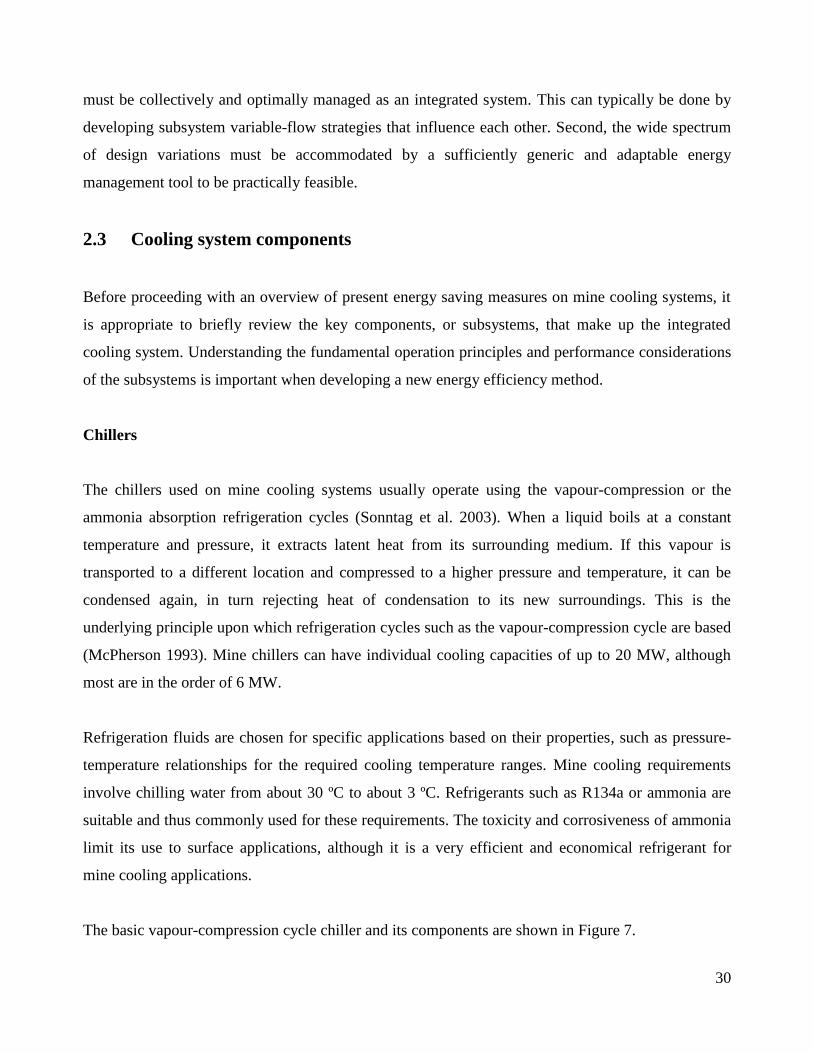
The basic vapour-compression cycle chiller and its components are shown in Figure 7.
31
Figure 7 Vapour-compression refrigeration cycle used in mine chillers
As shown in Figure 7, the main components of the chiller are the evaporator, condenser, compressor
and expansion valve. The evaporator and condenser are typically shell-and-tube heat exchangers,
although plate-type exchangers are also used where space constraints dominate the design (Çengel
2006). The refrigerant usually flows in the shell and the water inside the tubes. The latent heat of
evaporation in the refrigerant is used to transfer heat from the water in the evaporator, chilling the
water in the process. Inversely, the rejected heat of the process is transferred to the condenser water.
The refrigerant compressor drives the vapour-compression process by compressing the refrigerant
vapour and therefore shaft work input is required (Sonntag et al. 2003). The thermodynamic
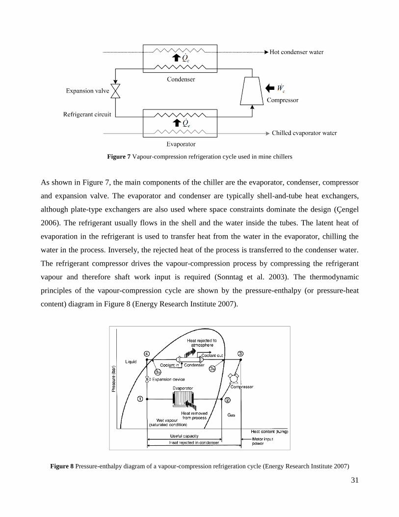
principles of the vapour-compression cycle are shown by the pressure-enthalpy (or pressure-heat
content) diagram in Figure 8 (Energy Research Institute 2007).
Figure 8 Pressure-enthalpy diagram of a vapour-compression refrigeration cycle (Energy Research Institute 2007)
32
Figure 8 shows that the superheated refrigerant is compressed by the compressor to a higher pressure
and associated temperature (2-3). The refrigerant then de-superheats and condenses at constant
pressure in the condenser (3-4), before being throttled by means of an expansion valve to a low
temperature and pressure (4-1). The refrigerant subsequently evaporates at constant low pressure and
temperature in the evaporator (1-2), before once again entering the suction side of the compressor
(Sonntag et al. 2003).
The ammonia absorption cycle is also used on some mine cooling systems. This cycle uses the same
basic principles already described to achieve the cooling effect. However, there are differences in the
manner that compression of the refrigerant is achieved. Absorption of low-pressure ammonia into
water and its compression and subsequent vapour extraction is achieved by a network consisting of a
pump, absorber, liquid receiver, surge drum and compressor. The main advantage is that refrigerant
compression uses less electrical energy input per cooling load output than in vapour-compression
cycles (Sonntag et al. 2003).
Centrifugal and screw compressors are most commonly used in vapour-compression and ammonia
absorption cycles, respectively. Cooling loads are controlled by means of guide vanes in centrifugal
compressors and slide valves in screw compressors (Widell and Eikevik 2010). These control
methods continuously adjust the refrigerant flow rate and hence the latent heat transfer and cooling
capacity to ensure that a set evaporator outlet water temperature is maintained for variable inlet water
conditions (McQuay International 2005).
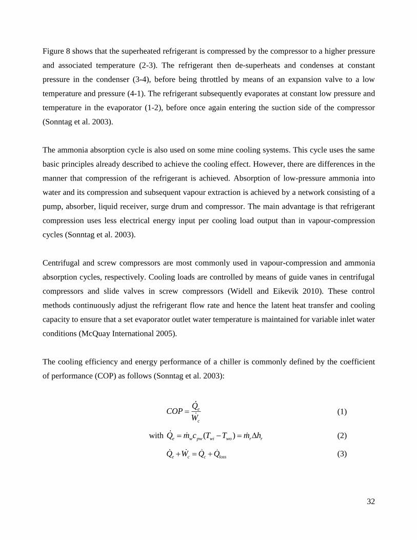
The cooling efficiency and energy performance of a chiller is commonly defined by the coefficient
of performance (COP) as follows (Sonntag et al. 2003):
e
c
QCOP
W
(1)
with ( )e w pw wi wo r rQ m c T T m h
(2)
e c c lossQ W Q Q
(3)
33
A high COP value indicates that a chiller is operating energy efficiently. The COP of small- to
medium-sized chillers (below 1 050 kW cooling capacity) is usually about 3, while it increases to
around 6 for large chillers as discussed in this study (Sonntag et al. 2003).
The COP is affected by relative changes in the cooling load and compressor input power. As
mentioned previously, the capacity control system of a chiller compressor ensures that a constant
evaporator water outlet temperature is maintained (McQuay International 2005). From Equation 2 it
can therefore be observed that the evaporator cooling load, for a set water outlet temperature, is
influenced by the water flow rate and the water inlet temperature.
When the water-side cooling load changes, the compressor capacity control ensures that the
refrigerant flow rate changes correspondingly. This results in a change in compressor input power.
Theoretically then, the COP of a thermally balanced chiller should remain relatively constant under
various operating conditions. However, in practice the COP is not always constant.
The tendencies of the COP to increase at reduced evaporator water flow rates and to decrease at
reduced condenser water flow rates have been reported (Gordon et al. 2000, Romero et al. 2011).
When water flow rates are varied, they must be optimally controlled to changing load conditions
while counterbalancing adjustments in compressor power controlling components, such as guide
vane controllers (Bahnfleth and Peyer 2004). The effect of a variable water flow strategy on the
chiller COP therefore depends on the control strategy and how well it manages the changing cooling
load.
The reliable mechanical performance of a chiller is also an important consideration. Degradation in
chiller performance will be reflected by a reduced COP, as already discussed, and by the machine
shutting down (“tripping”) as a fail-safe measure. This can be the result of various factors. Low
water flow rates or dirty water can cause sediment build-up and lead to poor heat transfer rates in the
heat exchangers (Çengel 2006). Low water flow rates and cold evaporator inlet temperatures can also
lead to compressor surges (McQuay International 2005). It is therefore not only important that COP
values are maintained, but also that the daily operation of machines is not adversely affected by
tripped conditions caused by perceived energy efficient changes to the cooling system.
34
Cooling towers
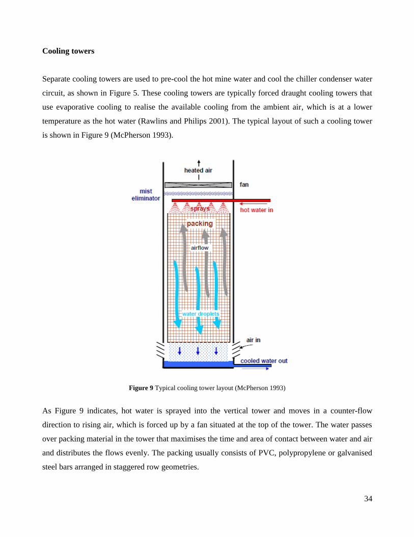
Separate cooling towers are used to pre-cool the hot mine water and cool the chiller condenser water
circuit, as shown in Figure 5. These cooling towers are typically forced draught cooling towers that
use evaporative cooling to realise the available cooling from the ambient air, which is at a lower
temperature as the hot water (Rawlins and Philips 2001). The typical layout of such a cooling tower
is shown in Figure 9 (McPherson 1993).
Figure 9 Typical cooling tower layout (McPherson 1993)
As Figure 9 indicates, hot water is sprayed into the vertical tower and moves in a counter-flow
direction to rising air, which is forced up by a fan situated at the top of the tower. The water passes
over packing material in the tower that maximises the time and area of contact between water and air
and distributes the flows evenly. The packing usually consists of PVC, polypropylene or galvanised
steel bars arranged in staggered row geometries.

35
Heat is transferred from the water droplets to the air by a combination of convection (sensible heat
transfer due to the temperature difference between water and air) and evaporation (latent heat
transfer driven by the water phase change). The cooled water collects in a dam and is pumped out to
its required end-user. Some water is lost to evaporation and is thus made up by adding new water.
This usually accounts for no more than 0.2% of the total water circuit flow (ASHRAE 1988).
The performance of cooling towers depends on the water flow rate and inlet temperature, air flow
rate and inlet psychrometric conditions as well as the duration and quality of contact between air and
water droplets (McPherson 1993). Various measures are used to evaluate the performance of cooling
towers. These include the water- and air-side efficiencies, the cooling tower effectiveness and the
cooling tower factor of merit (Whillier 1977). These evaluations all depend on the influencing
factors mentioned previously.
The simplest way to evaluate the heat transfer efficiency of a cooling tower when only water-side
and inlet air conditions are measurable (as is most often the case in practice) is to consider the
cooling tower range, approach and water-side efficiency as follows (McPherson 1993):
wi woRange T T
(4)
( )wo ai wbApproach T T
(5)
( )
actual wi wow
ideal wi ai wb
Q T T
Q T T
(6)
It is apparent that an efficient cooling tower is indicated by a low approach value and thus also a high
water-side efficiency. The range merely quantifies the water-side temperature drop and should be
considered relative to the approach.
At steady state, the heat rejected from the cooling tower is equal to the heat gained in the process for
which cooling is required, such as the condenser or the underground mine processes. The theoretical
rate of heat rejected from the tower is therefore not dependent on its efficiency. However, changes in
the cooling tower efficiency will lead to changes in the temperature range achieved and therefore
directly influence the achieved steady-state water temperature supplied by the cooling tower.

36
Changing controllable factors such as air and water flow rates will directly influence the
effectiveness of cooling towers. For example, if the water flow and pressure is reduced unacceptably,
the spray pattern of a conventional fixed-orifice nozzle will cause uneven wetting of the fill material.
This may lead to reduced efficiencies and increased rates of scaling on the dry areas. The efficiency
can also be adversely affected by factors such as fouling of cooling tower fill material (Stroh 1982).
It is important to consider these effects when developing and implementing energy saving strategies
that involve altering design parameters.
Bulk air coolers
The BAC is also an evaporative spray chamber type of heat exchanger, similar to cooling towers.
However, the heat transfer direction is the inverse of the cooling tower because the inlet water is now
colder than the intake air wet-bulb temperature. The air is thus cooled to a lower wet-bulb
temperature. Vertical BACs are essentially the same in configuration as shown for cooling towers in
Figure 9. A duct is added to the air outlet to direct the cold air towards the required area. Horizontal
BACs are also common and can have multiple stages for versatility, as indicated in Figure 10
(McPherson 1993).
Figure 10 Typical horizontal BAC with two stages (McPherson 1993)
BACs and similar evaporative air coolers are used extensively on mines. The largest installations are
typically found as part of surface cooling systems as discussed previously. The main purpose of these
surface BACs is to cool the main shaft and haulages.
37
Underground BACs are found in cases where shaft ventilation air is at acceptable conditions, but
haulage and rock face conditions are not (ASHRAE 1988). Small cross-cut and spray chamber spot
coolers that use the same cooling principles are often used and positioned near the working face (Le
Roux 1975).
The performance indicators of a cooling tower stay exactly the same for a BAC, except that the
parameters are the opposite way around as depicted in Equations 4 to 6. This is because of the
reversed direction of heat transfer. One can therefore simply take the negative of the results obtained
from Equations 4 to 6.
Pumps
The water pumps used to distribute water in the chilled water, condenser water and BAC water
networks of mine cooling systems are usually centrifugal pumps that operate at fixed speeds. The
arrangement and size of the pumps and their motors depend on the application and required pressures
and flows. Electrical input power typically varies between 45 kW and 400 kW per pump.
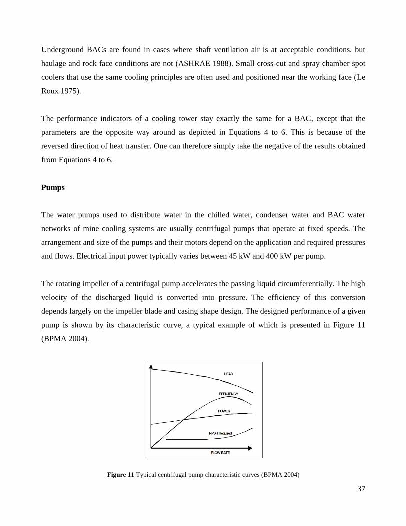
The rotating impeller of a centrifugal pump accelerates the passing liquid circumferentially. The high
velocity of the discharged liquid is converted into pressure. The efficiency of this conversion
depends largely on the impeller blade and casing shape design. The designed performance of a given
pump is shown by its characteristic curve, a typical example of which is presented in Figure 11
(BPMA 2004).
Figure 11 Typical centrifugal pump characteristic curves (BPMA 2004)

38
The curves in Figure 11 plot the pump’s delivered head, efficiency, power and required net positive
suction head (NPSH) as functions of the liquid flow rate. The region of optimal pumping efficiency
should be selected to coincide with the operating point of the pump. This point is the intersection of
the pump characteristic curve and the system resistance curve plotting the required pressure or head
against the system flow rate (White 2008).
Changes in pump impeller speed result in changes in the pump characteristic curves. This is because
affinity laws dictate that flow rate is proportional to rotational speed, pressure head increase is
proportional to the square of the rotational speed and input power is proportional to the cube of the
rotational speed (White 2008). Changes to the system, such as valve openings, have the effect of
changing the system resistance and the associated pressure and flow requirements. Figure 12 shows
the typical changes to pump curves when reducing the pump rotational speed by VSD (BPMA 2004).
Figure 12 Typical changes in pump characteristic curves when using a VSD (BPMA 2004)
The system curve plotted in Figure 12 is typical of a system that is dominated by frictional pressure
losses as opposed to static pressure losses. This is typically the scenario in cooling systems where the
pressure requirements are dictated by heat exchanger and cooling tower components. It can be seen
that speed reduction by VSD causes the operating point to move down an iso-efficiency line, thereby
maintaining the pumping efficiency while significantly reducing the absorbed power. This implies
that cooling system pumps should theoretically be well suited to speed reduction.

39
However, it is important to consider all the variables since reduced pump efficiencies lead to
increased wear rates and subsequently result in more frequent maintenance requirements and
increased lifecycle costs. It is thus important that the trade-off between reduced flow rate energy
savings and changes in pump efficiencies is considered.
There are also other factors that must be evaluated to ensure that pump lifecycle costs do not increase
significantly as a result of energy saving interventions. For example, the NPSH achieved must
remain higher than required to ensure that no cavitation problems occur. Also, the starting and
stopping methods of the pumps must also be such that no unnecessarily high mechanical stresses are
induced on rotating parts and bearings (BPMA 2004).
40
2.4 Existing energy saving measures
The discussion of large mine cooling system designs and their components provided a suitable
background for the following review of energy saving measures that have been developed in the
field. This is necessary to gain further insight into existing energy research and to identify areas of
potential improvement.
Large mine cooling system savings
Ideally, the original design features present on any cooling system should be optimally selected to
enable energy efficient operation. Various alternative configurations of subsystems and operation
methods should be considered for any specific application by considering atmospheric, thermal
loading and required operation conditions (Koziol and Chwiolka 2001).
On deep mines the overall efficiency of cooling operations was investigated in the 1980s when mine
deepening began to severely increase thermal loads. This resulted in system design changes, such as
BACs being installed on surface cooling systems, energy recovery water turbines being installed in
the water columns underground and the introduction of ice plants to support cooling operations (Van
der Walt and De Kock 1984). Although mine depths have increased even further since then, no major
system design changes have been widely implemented from an energy efficiency perspective. It is
therefore worthwhile to investigate and apply DSM incentives on the existing systems.
There have been DSM initiatives on mine cooling systems in recent times. The optimal use of
thermal storage in the form of underground chilled water dams in conjunction with load shifting
possibilities for underground cooling systems was investigated by Swart (2003). A simulation model
was developed to simulate and optimise the energy costs of existing underground cooling systems.
Focus was limited to an underground system of one mine and the potential for load shifting by
thermal storage.

41
A simple real-time control system to simulate and implement load shifting generically on cooling
systems was described by Van der Bijl (2007). The main focus was on moving chiller operations out
of the peak times (Eskom 2012). The system was implemented on two surface cooling systems,
shifting loads of 3.6 MW and 4.0 MW respectively. Load shifting by scheduling chillers optimally
was further implemented on a parallel chiller cooling system by Calitz (2006). In this way a daily
average electrical load of 3.6 MW was shifted. A similar load shifting study was done by Schutte
(2007) on a cascade surface cooling system, realising an average daily load shift of 4.2 MW.
Although these load shifts translated to significant cost savings and peak-time demand reductions,
the average energy usage of the systems remained constant.
The optimal scheduling of pre-cooling tower supply water and the control of evaporator inlet water
temperature by purposefully recycling chilled water was reported by Pelzer et al. (2010). The main
objective was to improve chiller COP by reducing the inlet water temperature. Annual energy
savings of 32 416 MWh were reported between three sites. However, the energy savings were not
offset against the added daily cooling load caused by the recirculation of chilled water.
The described DSM methods were all successful in achieving or showing potential energy cost
savings on cooling systems. However, the majority focused on load shifting models and did not
thereby improve the energy efficiency of the systems. Furthermore, all of the initiatives were based
on improving the control of existing system equipment, some of which have been operational for
years. As discussed earlier, mine cooling system operational methods are often very energy
inefficient. A continual review and employment of the latest available technology is required if the
changing needs of the mining industry are to be met (Van der Walt and Whillier 1978).
An important strategy that can be considered when attempting to reduce cooling system energy usage
is to consider lowering the cooling demand itself. This is most commonly done when there is
relatively simple control over the cooling loads such as in residential applications (Hatamipour et al.
2007) or commercial building cooling systems (Bahman et al. 2012).
Mine cooling demands are generally more complex because of the variety and nature of the chilled
water users. Methods have been developed to reduce and manage water usage in the water
reticulation systems of mines (Gunson et al. 2010, Vosloo et al. 2012).
42
These methods reduce the cooling load by reducing the total volume of water that must be chilled.
However, the exact effects on the energy usage of mine cooling systems have not been quantified
properly. It is possible that the inefficient operation methods of most cooling systems lead to the
chilled water volume demand reduction not realising its full saving potential.
It can therefore be said that energy saving measures have been taken on the cooling demand side and
the optimal control of existing mine cooling systems. However, insufficient work has been done in
implementing available technologies to address the inefficient operation methods of these large
cooling systems.
Other cooling system savings
It is worthwhile to consider energy saving methods based on available technologies that are currently
applied to other cooling systems in order to investigate viable opportunities on large mine cooling
systems. An area in which a lot of energy-related research has been done is cooling systems in
residential and commercial buildings’ central heating, ventilation and air conditioning (HVAC)
systems. The incentive for research in buildings’ HVAC energy usage is their widespread global use
and the fact that it accounts for about 35% of total building electrical energy usage (Henze 1995).
Many energy efficient initiatives have been investigated and implemented on medium-sized HVAC
systems. Load-based speed control of condenser pumps and condenser cooling tower fans was
investigated and applied on different chiller systems by Yu et al. (2008, 2010). Hackner et al. (1984)
presented an equal loading rate method to operate chillers, a method now commonly used in HVAC
systems. Khandelwal et al. (2011) showed that the use of regenerative evaporative coolers presents
considerable electrical energy savings. A model to determine the optimal condenser water flow rate
and evaporator water outlet temperature set point was presented by Yao et al. (2004). The
improvement in the energy performance of chillers by considering variable evaporator water flow
rate has also gained considerable attention (Lee and Yik 2002, Yu and Chan 2008).

43
The cooling systems on which the discussed initiatives are applicable are typically smaller in size
and present different thermal loading requirements to those found on mines and in large industrial
settings (Lu et al. 2011). This makes it not directly applicable to mine cooling systems. However, a
good overview of popular energy management practices and available technology is gained. One
concept commonly used in HVAC investigations to enhance the energy performance of cooling
systems is the application of VSD technology in variable-flow strategies (Yu and Chan 2010).
Since the 1970s, major technology and material advances in power electronics have led to VSD
technology becoming a key factor in the energy efficient design of suitable systems (Bose 2000).
VSDs modulate the electrical frequency supplied to electric motors and thereby provide continuous
control over the motor speed. The operation capacity of the driven system can thus be varied
according to the demand. This realises electrical energy savings in part-load conditions (Saidur et al.
2011). VSDs are applied to various systems such as compressors, conveyors, winders, pumps and
fans (De Almeida et al. 1990, Saidur 2010).
As described in previous sections, mine cooling systems are good examples of systems with variable
pump duty requirements. Buffering is provided by the hot and chilled water storage dams,
unnecessary recycling of chilled water is often employed when dams are full and water flow
throttling is usually used for constant water flow control. These factors indicate that mine cooling
systems should be well suited to variable water flow strategies. Because of the apparent potential
shown by VSD application on mines, VSDs are discussed further in Chapter 3 where their potential
on mine cooling systems is evaluated in greater detail.
It can be concluded that mine cooling system designs were improved over the past 40 years and
recent advances have been made in load shifting and control improvement of existing cooling
systems. More work is required however, especially regarding the application of available energy
efficient technology on these plants. Energy saving measures commonly employed in building
HVAC systems were investigated and it was found that variable-speed strategies are widely used.
Mine cooling systems present good potential for variable pumping applications. It therefore seems
reasonable to introduce VSDs on mine cooling systems, given that the water flow can be well
modulated according to the loads and unique requirements of the mine systems through a new
control strategy. This emphasises the conclusive findings of Chapter 1.3.

44
2.5 Mine service delivery requirements
Mine cooling systems play integral roles in the productive functioning and safety of deep mines. It is
therefore important to consider the general as well as the specific service delivery requirements of
these systems when formulating an energy saving strategy. Such requirements will also be used to
measure the success of strategy implementation.
The foremost priority of a mine cooling system is to enable the complete mine cooling and
ventilation system to function properly and reliably (Van der Walt and De Kock 1984). The chilled
water supplied to the mine and to the BAC must therefore always be at the correct temperature and
immediately available on demand. Practically, this means that the chilled water dam temperature and
level should be maintained within the limits specified by the mine at all times (Calitz 2006).
The daily average value of the required chilled water dam temperature and level should not be the
only requirements to be maintained after implementing an energy saving intervention. The daily
profiles are equally important. This is because a typical daily profile of the chilled water dam level
reflects the demand profile throughout the day. The water demand remains unchanged after an
energy intervention on the cooling system. Therefore, the supply profile should remain unchanged
accordingly, or improve if possible.
A further implication of mine service delivery requirements is that the ventilation air sent
underground must always ensure and maintain an acceptable and productive working environment. It
has been shown that worker productivity decreases when wet-bulb temperatures exceed 28 ºC
(Le Roux 1990). South African mines therefore restrict the working area wet-bulb temperature to
27.5 ºC (Vosloo et al. 2012). This value must be adhered to in a cooling energy saving intervention
applied to the BAC system. At the very least, current underground air wet-bulb temperatures must
not be adversely affected.

45
Productivity and safety are main priorities on any mine (Schutte 2007). If it is ensured that the
specified chilled water dam temperature and chilled water availability as well as the underground air
wet-bulb temperatures remain acceptable to the mine, there will be no adverse effects on productivity
and safety of the mine and its workers. These requirements must be adhered to when developing a
new DSM method that involves altering cooling systems component operations.
46
2.6 Cooling system performance considerations
The performance of mine cooling system components is also of prime concern when developing an
energy saving strategy. It would be futile to realise energy savings with system components
operating unacceptably inefficient, resulting in long-term cost increases relating to higher
maintenance and replacement costs.
The main objective regarding system performance is that an energy saving intervention should not
degrade the existing state and operation of the system in any way (Calitz 2006). Factors that typically
need to be considered include COPs (of both the chillers and the integrated cooling system), general
chiller performance, cooling tower, BAC and water pump efficiencies, as well as effects on the
electrical power supply system.
The energy efficient operation of an integrated cooling system is usually evaluated by the global
system COP as follows (Sonntag et al. 2003):
cooling system
cooling system
QGlobal COP
W
(7)
with , ( )cooling system w daily avg pw hot dam chilled damQ m c T T
(8)
cooling systemW W in cooling system
(9)
It can be seen that the thermal load considered is the total load of the integrated cooling system and
that the input power includes all electrical energy users, such as chiller compressors, water pumps
and cooling tower fans. A reduction in the average electrical energy usage without proportionally
reducing the cooling load will be indicated by an increased global COP. A global energy efficiency
strategy can therefore conveniently be evaluated by this parameter.
The evaluation of chiller COPs as well as cooling tower, BAC and pump efficiencies are discussed in
Chapter 2.3 under the respective headings. More detail of considerations with regards to the
electrical system is given in Chapter 3 when discussing VSDs.

47
It can be concluded that performance considerations of large cooling system equipment need to be
taken into account as far as possible in the development of a variable water flow energy saving
strategy. This will ensure that realised energy savings are not cancelled out by degraded performance
of subsystems. It is also important that the mentioned factors are evaluated for comparable
conditions before and after strategy implementation to determine the effect of an energy saving
intervention on the performance of the mine cooling system and its components.
48
2.7 Existing energy management systems
There is a strong relation between energy efficiency, energy management and control systems when
considering them in terms of performance, operation, equipment and technology (Xia and Zhang
2010). This is to be expected, since the high level objectives of an energy efficiency strategy are
usually required to be realised by the objectives of a lower level control system. It follows that it is
necessary to develop a new and suitable energy management system to integrate and implement the
energy saving strategies developed in this study.
It has been shown that optimised system control should occur as close as possible to real-time to
react to system disturbances and enable maximum energy savings (Van Staden et al. 2011). The
importance of transforming and simplifying complex modelling and control problems, such as the
global optimisation of cooling systems, has also been demonstrated (Lu et al. 2005). Furthermore,
Chai and Yeo (2012) recommend an integrated systems approach to energy efficiency as this is
usually important to ensure sustainability. An effective energy management system should therefore
be simple, robust, practical and suitable to real-time applications.
Mine cooling energy management systems
Mine ventilation control systems were initially investigated by McPherson et al. (1972) and
Meriluoto (1983). A high order nonlinear control model of coal mine ventilation networks that
requires full state measurement throughout the entire network was developed by Hu et al. (2003). A
similar, but decentralised mine ventilation control model was developed by Koroleva et al. (2007).
The shortcomings of these models are that they are very complex and do not include the control of
integrated cooling systems of mine ventilation networks.
49
Integrated simulation models of mine ventilation networks have also been developed and are
commercially available (ENVIRON 1997, Wu and Topuz 1998, Bluhm et al. 2012). These packages
typically perform a full thermodynamic analysis of the heat distribution in mine systems and can
make recommendations regarding the cooling system design. They are well suited as tools to
optimise the energy efficient design of a given system. However, the models are independent
packages and are not suitable for use as dynamic real-time cooling system energy managers.
Van der Bijl (2007) developed an energy management system that connects to a mine cooling
Supervisory, Control and Data Acquisition (SCADA) system in real-time. The energy management
system is able to read and control existing equipment with the objective of implementing load shifts
as discussed earlier. This system proved to be practically feasible. However, it did not consider the
integrated dynamic control of new technologies to realise DSM energy savings, but instead merely
focused on scheduling existing equipment.
Other energy management systems
As was the case with the review of existing energy saving strategies, it is worth considering state-of-
the-art energy management systems in other fields. Real-time control systems have been developed
for water pumping networks. A model predictive control system was developed by Van Staden et al.
(2011) for load shifting of water pumping schemes. Blanchini and Viaro (2010) reported a switched
control technique to drive a large water distribution system to equilibrium disturbances presented by
the water demand. Vosloo et al. (2012) described a system that simulates, optimises and controls the
water pump system of mines. Although these methods do not pertain to large mine cooling systems,
they do provide insight into the energy-conscious control of water systems.
Various real-time control systems have been developed in the field of building HVAC systems. Ma
and Wang (2009) developed an optimal sequence controller for central air-conditioning water pumps
fitted with VSDs. Wang et al. (2004) investigated the real-time control of HVAC system cooling
coils. The optimal control of variable speed pumps in HVAC systems were reported by Tillack and
Rishel (1998) as well as by Green (1994). Lee et al. (2011) developed an energy management system
to be used jointly with facility monitoring and control systems (FMCS). This system monitors and
optimises HVAC and chiller energy consumption of industrial information technology (IT) plants.

50
These control methods provide a good background of what is presently available. However, the
system requirements of large cooling systems on mines differ significantly, so that these models
cannot simply be adjusted to suit mine cooling needs.
Bayindir et al. (2011) emphasises the general need for simple, integrated energy management
methods that provide remote control and real-time energy consumption monitoring. One such
method has been developed for building systems by Marinakis et al. (2012). The interactive software
tool of the developed system is shown in Figure 13 as an example of a typical energy management
platform (Marinakis et al. 2012).
Figure 13 Typical example of an energy management system user platform (Marinakis et al. 2012)
It can be seen in Figure 13 that the system has the ability to monitor in real-time, or extract historic
trends of critical system parameters such as temperatures, power and energy usage of the integrated
system. The parameters are presented simply and clearly. However, from a real-time monitoring
perspective it is not immediately clear what the system layout looks like or what the energy
management system controls. Graphic representations that are intuitive and easy to use are therefore
recommended as part of the requirements for such a system by Avouris (2001).
51
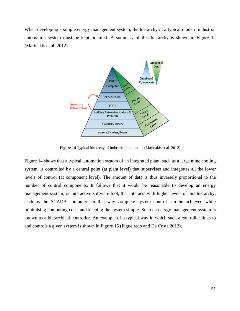
When developing a simple energy management system, the hierarchy in a typical modern industrial
automation system must be kept in mind. A summary of this hierarchy is shown in Figure 14
(Marinakis et al. 2012).
Figure 14 Typical hierarchy of industrial automation (Marinakis et al. 2012)
Figure 14 shows that a typical automation system of an integrated plant, such as a large mine cooling
system, is controlled by a central point (at plant level) that supervises and integrates all the lower
levels of control (at component level). The amount of data is thus inversely proportional to the
number of control components. It follows that it would be reasonable to develop an energy
management system, or interactive software tool, that interacts with higher levels of this hierarchy,
such as the SCADA computer. In this way complete system control can be achieved while
minimising computing costs and keeping the system simple. Such an energy management system is
known as a hierarchical controller. An example of a typical way in which such a controller links to
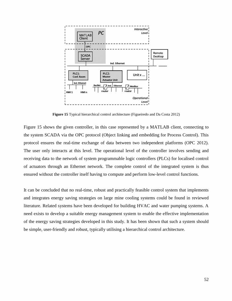
and controls a given system is shown in Figure 15 (Figueiredo and Da Costa 2012).
52
Figure 15 Typical hierarchical control architecture (Figueiredo and Da Costa 2012)
Figure 15 shows the given controller, in this case represented by a MATLAB client, connecting to
the system SCADA via the OPC protocol (Object linking and embedding for Process Control). This
protocol ensures the real-time exchange of data between two independent platforms (OPC 2012).
The user only interacts at this level. The operational level of the controller involves sending and
receiving data to the network of system programmable logic controllers (PLCs) for localised control
of actuators through an Ethernet network. The complete control of the integrated system is thus
ensured without the controller itself having to compute and perform low-level control functions.
It can be concluded that no real-time, robust and practically feasible control system that implements
and integrates energy saving strategies on large mine cooling systems could be found in reviewed
literature. Related systems have been developed for building HVAC and water pumping systems. A
need exists to develop a suitable energy management system to enable the effective implementation
of the energy saving strategies developed in this study. It has been shown that such a system should
be simple, user-friendly and robust, typically utilising a hierarchical control architecture.
53
2.8 Conclusion
Considerations relevant to large cooling systems and important for the successful development of a
new energy saving strategy were reviewed. It was found that existing layouts and operational
methods of mine cooling systems often result in the chilled water supply exceeding the demand
without taking into account optimal and energy efficient equipment operations. The potential for an
energy efficiency strategy to better match supply to demand is therefore apparent on these systems.
An overview was given of the various components that make up mine cooling systems. This included
basic operational principles and typical performance indicators that will have to be calculated to
assess an energy efficiency intervention.
A review of existing energy saving initiatives showed that recent advances have been made in load
shifting and control improvement of cooling systems. However, more work is required regarding the
implementation of available technologies. Energy saving measures employed in building HVAC
systems were investigated and it was found that variable-speed strategies are widely used. Given the
suitability of mine systems to variable chilled water supply, it would be reasonable to formulate a
strategy to implement VSDs on mine cooling systems.
Mine cooling system service delivery requirements were investigated. It was shown that if the chilled
water temperature and availability as well as underground wet-bulb temperatures are maintained
within acceptable limits, there will be no adverse effects on productivity and safety of the mine and
its workers. An overview of integrated cooling system performance considerations indicated that
various subsystem parameters need to be considered to ensure that realised energy savings are not
cancelled out by degraded system performance.
A review of relevant energy management systems indicated that no real-time, robust and practically
feasible control system that implements and integrates energy saving strategies specifically on large
mine cooling systems currently exists. There is therefore a need to develop a unique and suitable
control and energy management system to enable the effective implementation of the energy saving
strategies developed in this study.

54
It is concluded that the reviewed large cooling system considerations emphasised the perceived need
for a variable water flow strategy and energy management system for mine cooling systems. The
context and constraints of such an initiative were provided. It is necessary to proceed by preliminary
investigating and estimating the savings that could be realised on large mine cooling systems in a
large context and to identify where exactly the most potential lies before developing and
implementing the new DSM method.