chapter 2: heating envelope building measures
TRANSCRIPT
Wisconsin Weatherization Field Guide 2-1 July 2021
Chapter 2: Heating Envelope Building Measures
2.1 Heating Envelope Insulation
The building heating envelope comprises those surfaces that function as the thermal boundary
between conditioned and unconditioned spaces. These surfaces may include, but are not
limited to, exterior walls, attics, foundations, and exposed floors. Insulation reduces heat
transmission by slowing conduction, convection, or radiation through the building envelope. The
various insulating materials in the building make up the thermal boundary — the boundary that
separates conditioned space from unconditioned space. Airtight materials that cover the walls,
floor, and ceiling to prevent air movement form the pressure boundary. The thermal and
pressure boundaries should be as continuous as possible and aligned properly so the insulation
works effectively. The pressure boundary must be addressed before proceeding with work on
the thermal boundary except in circumstances where both pressure and thermal boundaries are
addressed at the same time, through measures such as dense-pack insulation. See Chapter 1 –
Section 1.5.3 for information on how to address the pressure boundary.
When insulation is installed, a dated insulation certificate is affixed near an attic hatch, electrical
panel, or other visible location, with information including:
1. Insulation type
2. Coverage area
3. R-value
4. Installed thickness and settled thickness
5. Number of bags installed in accordance with manufacturer instructions
6. SPF insulation shall include:
a) Type of two-part foam
b) Density
c) Flame and smoke spread
Spray Polyurethan Foam (SPF) and rigid insulation require a flame spread and smoke
development index of 75/450 or less when testing in accordance with ASTM E84 or UL 723, and
all other insulation requires an index of 25/450 or less. SPF used for duct sealing or insulation
requires a flame spread and smoke development index of 25/450 or less. Refer to Appendix C
in the Weatherization Program Manual for additional material specifications.
2.2 Attic and Roof Insulation
2.2.1 Pre-insulation Attic and Roof Insulation Prep
Perform these preparatory steps and safety procedures before installing attic insulation:
1. Vent all exhaust appliances to the outdoors, as specified in Chapter 3 – Section 3.13
using a dedicated exhaust termination. Seal and insulate exhaust ducts to R-8 to prevent

2-2 Wisconsin Weatherization Field Guide July 2021
condensation inside the duct. Check all fans for proper backdraft-damper operation.
Repair or replace the damper, or the entire fan assembly, if the damper does not operate
freely.
2. Isolate insulation a minimum of 3 inches from masonry chimneys and per manufacturer
instruction for metal vents, using rigid damming material. Do not allow insulation to spill
into clearance spaces.
3. Repair roof leaks and address other attic-related moisture problems before insulating
attic.
4. Confirm all wire splices are enclosed in electrical junction boxes. Mark all junction boxes
that will be covered with insulation with a sign or flag.
5. When not removing knob-and-tube wiring, maintain a 3-inch clearance from insulation
around live knob-and-tube wiring using appropriate materials. See Electrical Safety in
Chapter 5 – Section 5.7.
6. Remove or perforate existing vapor retarders on the cold side of the insulation.
7. Check the manufacturer’s instructions to determine if fixtures can be covered with
insulation. If fixtures cannot be covered with insulation, or if Insulation Contact (IC) rating
is unknown, keep all insulation three inches from these fixtures and do not install
insulation over the top of the cover.
8. If heating system ductwork runs through the attic, seal and insulate as appropriate (see
Duct Leakage and Duct Insulation in Chapter 3 – Sections 3.4.2 and 3.4.3). Do not apply
duct insulation to ducts that will be surrounded by R-8 or more of loose-fill insulation.
9. If the attic is used for storage, eliminate or reduce the amount of storage area with the
customer’s approval. Build an insulation dam around the area. If items are present
during insulation, temporarily either remove items from area or cover with plastic or a
tarp.
10. Install depth markers for installed insulation every 300 square feet of attic area, with the
measurement beginning at the air barrier.
11. When a whole-house fan is encountered in a home, construct a box around the fan at a
height to protect the fan housing and motor from insulation. Insulate the exposed sides
and top of the box assembly to the same R-value as the adjoining insulation. Use the
appropriate adhesive or mechanical fasteners.
12. Consider placing a fiberglass batt on top of the exhaust fan housing in the attic before
blowing insulation. The batt will prevent loose-fill insulation from spilling into the home if
the fan is replaced in the future.

Wisconsin Weatherization Field Guide 2-3 July 2021
2.2.2 Attic Ventilation
Install attic ventilation when it is needed. When
installing ventilation, there should be an equal
distribution of vent area across all attic areas
whenever possible. Split the net free area of attic
ventilation equally between high and low venting, if
possible. Consult state and local building codes for
requirements on the minimum amount of attic
ventilation.
Gable Vents
Install gable end vents as high in the gable end as possible and above the final level of
the attic insulation. Build a dam in front of existing gable vents if insulation comes up to
the bottom of the vent.
Roof Vents
Install the top flashing of the roof vents under asphalt shingles and mechanically fasten and seal
with plastic roof cement or with products specifically designed for this purpose. Center all roof
vents between rafters. Where possible, mount vents no closer than 12 inches (measured
vertically) from the ridge of the roof.
Soffit Vents
When soffit venting is required, use products
specifically designed for this purpose. Eave chutes
allow the installation of the maximum amount of
insulation over the exterior top-plate. Chutes can
also prevent wind-washing of the insulation, which
degrades the insulation’s R-value. Install eave
chutes as necessary to promote sufficient
ventilation of the attic.
Mechanically fasten eave chutes at the top and
install blocking at the base to prevent insulation
from spilling over into the soffit area. In rafter
cavities where a chute is not installed, make sure
the cavity is blocked with fiberglass batts or a rigid
barrier to prevent spillover into the soffit area.
Chutes must be long enough to extend at least 6
inches above the final insulation level, and at least
one inch of clearance between the insulation and
roof deck material.
Low and high attic ventilation: A moderate amount of ventilation creates air exchange with outdoors.
Soffit chute: Allows installation of maximum amount of insulation in this cold area. Also prevents wind washing and
airway blockage by blown insulation.

2-4 Wisconsin Weatherization Field Guide July 2021
2.2.3 Attic Accesses, Walk-up Stairways, and Doors Attic Accesses
Perform these tasks to address attic accesses, walk-up stairways, and doors prior to insulation:
1. Insulate accessible attic accesses to the R-
value of the adjacent attic insulation or to the
maximum structurally allowable, whichever is
lower. Permanently attach the insulation and
ensure it is in complete contact with the air
barrier. Access must be operable, weather-
stripped, and air sealed.
2. Install durable damming material to maintain the
R-value of the attic insulation up to the access,
allow repeated access to the attic, and to
prevent loose-fill insulation from entering the
home.
3. Post warnings in access to attics with asbestos-containing materials or vermiculite. See
the Wisconsin Weatherization Program Manual (Chapter 9 – Health & Safety) for more
information about asbestos.
Walk-Up Stairways and Doors
Establish a continuous insulation and air barrier around or over the top of an attic stairway. If the
attic is accessed using a stairwell and standard vertical door, there are two methods for
treatment.
Method 1
Insulate the walls of the stairwell, as well as beneath
landings, stair treads, and risers. Insulate and weather-
strip the back of the door to the R-value of the adjacent
wall insulation or the maximum structurally allowable,
whichever is lower.
When planning to insulate stairwells, investigate for
barriers, such as fire blocking, that might prevent
insulation from filling cavities. Consider which
passageways may lead to other areas where insulation
should not be installed, such as closets or chimney
chases. Balloon framed walls and deep stair cavities
complicate this measure.
Wisconsin Weatherization Field Guide 2-5 July 2021
Method 2
Establish the thermal boundary at the ceiling level by installing an insulated and air sealed
horizontal hatch at the top of the stairs. Insulate the hatch to the R-value of the adjacent attic
insulation or the maximum structurally allowable, whichever is lower.
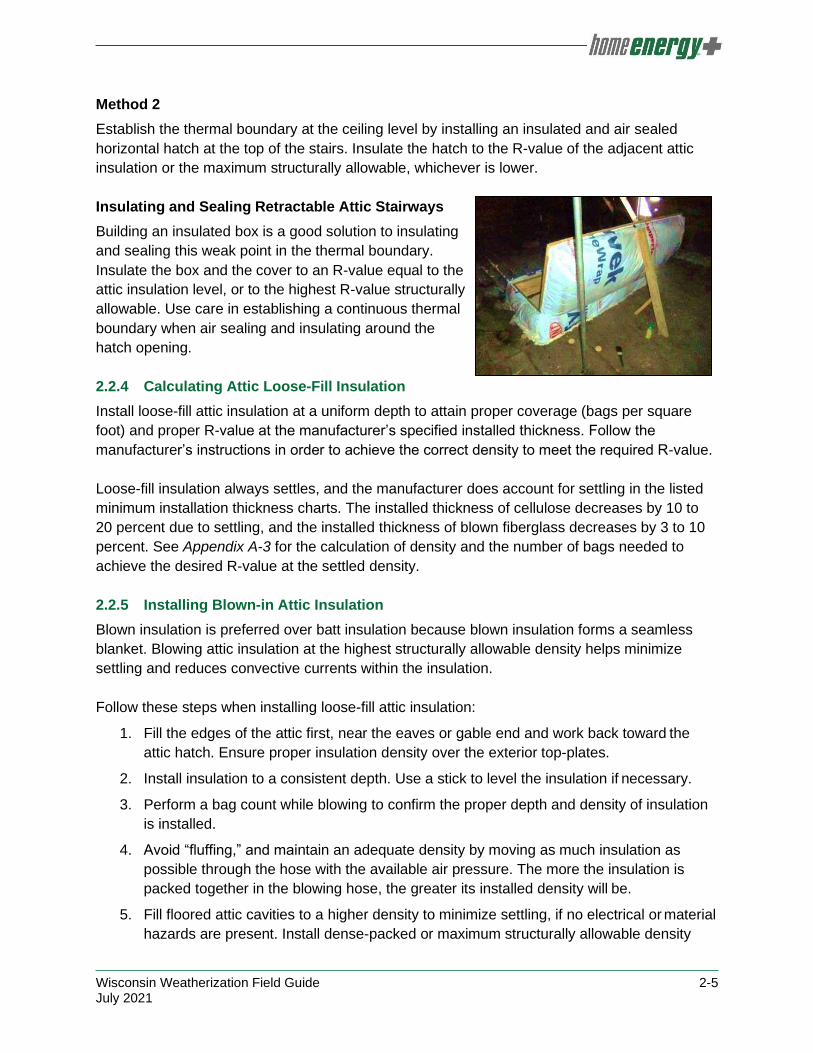
Insulating and Sealing Retractable Attic Stairways
Building an insulated box is a good solution to insulating
and sealing this weak point in the thermal boundary.
Insulate the box and the cover to an R-value equal to the
attic insulation level, or to the highest R-value structurally
allowable. Use care in establishing a continuous thermal
boundary when air sealing and insulating around the
hatch opening.
2.2.4 Calculating Attic Loose-Fill Insulation
Install loose-fill attic insulation at a uniform depth to attain proper coverage (bags per square
foot) and proper R-value at the manufacturer’s specified installed thickness. Follow the
manufacturer’s instructions in order to achieve the correct density to meet the required R-value.
Loose-fill insulation always settles, and the manufacturer does account for settling in the listed
minimum installation thickness charts. The installed thickness of cellulose decreases by 10 to
20 percent due to settling, and the installed thickness of blown fiberglass decreases by 3 to 10
percent. See Appendix A-3 for the calculation of density and the number of bags needed to
achieve the desired R-value at the settled density.
2.2.5 Installing Blown-in Attic Insulation
Blown insulation is preferred over batt insulation because blown insulation forms a seamless
blanket. Blowing attic insulation at the highest structurally allowable density helps minimize
settling and reduces convective currents within the insulation.
Follow these steps when installing loose-fill attic insulation:
1. Fill the edges of the attic first, near the eaves or gable end and work back toward the
attic hatch. Ensure proper insulation density over the exterior top-plates.
2. Install insulation to a consistent depth. Use a stick to level the insulation if necessary.
3. Perform a bag count while blowing to confirm the proper depth and density of insulation
is installed.
4. Avoid “fluffing,” and maintain an adequate density by moving as much insulation as
possible through the hose with the available air pressure. The more the insulation is
packed together in the blowing hose, the greater its installed density will be.
5. Fill floored attic cavities to a higher density to minimize settling, if no electrical or material
hazards are present. Install dense-packed or maximum structurally allowable density
2-6 Wisconsin Weatherization Field Guide July 2021
insulation in floored attic cavities when hidden bypasses have not been addressed by
other methods.
6. Add additional insulation over floored attics not used for storage, as needed to achieve
the specified R-value.
2.2.6 Installing Attic Batt Insulation
Follow these steps when installing fiberglass batts horizontally in the attic:
1. Install unfaced fiberglass batt insulation. Cut batts carefully to ensure a tight fit against
the ceiling joists and other framing.
2. Install two layers of batt insulation at a right angle to each other. This practice minimizes
voids and produces better thermal resistance.
2.2.7 Installing Attic Insulation in 1½ Story Homes (Finished Attics)
Finished attics in 1½-story homes
require special care when installing
insulation. They often include four
separate attic sections requiring
different sealing and insulating
methods:
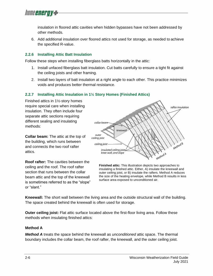
Collar beam: The attic at the top of
the building, which runs between
and connects the two roof rafter
attics.
Roof rafter: The cavities between the
ceiling and the roof. The roof rafter
section that runs between the collar
beam attic and the top of the kneewall
is sometimes referred to as the “slope”
or “slant.”
Kneewall: The short wall between the living area and the outside structural wall of the building.
The space created behind the kneewall is often used for storage.
Outer ceiling joist: Flat attic surface located above the first-floor living area. Follow these
methods when insulating finished attics:
Method A
Method A treats the space behind the kneewall as unconditioned attic space. The thermal
boundary includes the collar beam, the roof rafter, the kneewall, and the outer ceiling joist.
outer ceiling joist
Finished attic: This illustration depicts two approaches to insulating a finished attic. Either, A) insulate the kneewall and outer ceiling joist, or B) insulate the rafters. Method A reduces the size of the heating envelope, while Method B results in less surface area exposed to unconditioned air.

Wisconsin Weatherization Field Guide 2-7 July 2021
Follow these steps to treat the attics using Method A:
1. Seal and carefully insulate built-in closets, dressers, or cabinets that protrude into the
thermal boundary through the kneewall. Two-part foam can be effective at sealing and
insulating these areas from inside the kneewall attic. See General Information on Spray
Polyurethane Foam (SPF) in Appendix A-4 for additional information.
2. Create an airtight, permanent seal in the floor-joist space under the kneewall. Insert
pieces of rigid board insulation, drywall, or ductboard in between each joist, and seal the
perimeter of each piece with one-part foam; or by inserting a fiberglass batt into the
cavity and spraying its face with two-part foam, or by using the Bag Method to blow a
tight plug of dense-packed cellulose into the joist cavities.
To use the Bag Method: place a
plastic or mesh bag over the end of
the fill tube and insert the tube and
bag into the cavity. While holding on
to the bag, start blowing insulation
into the bag until full, then push the
remaining part of the bag into the
cavity. The bag will limit the amount
of insulation it takes to plug this
area.
3. Ensure insulation coverage is
adequate where the kneewall meets
the roof rafter and where the roof
rafter meets the collar beam.
4. Insulate the roof rafters using
dense-packed insulation. The roof
rafters can be insulated from either
the collar beam attic or the outer
ceiling joist attic. Ensure the
opposite end has a barrier installed.
Alternatively, dam both ends of each
cavity and blow the roof rafters from
the interior, like interior wall
insulation. See Dense-Packed Wall Insulation from the Interior in Chapter 2 ̶ Section
2.3.5.
air barrier
Finished attic best practices: Air sealing and insulation combine to dramatically reduce heat transmission and air
leakage in homes with finished attics.

2-8 Wisconsin Weatherization Field Guide July 2021
5. Insulate kneewalls using dense-packed
insulation, fiberglass batts, or two-part foam. If
dense-packing the kneewalls, prepare for
insulation installation by fastening a vapor-
permeable material to the cold side of the
kneewall studs with reinforcement as needed.
If the attic area remains accessible two-part
foam insulation must be covered with a
thermal barrier.
6. When insulating kneewalls with batt insulation,
use appropriately sized batts to fit into the stud
cavities.
7. Cover existing and/or installed fiberglass batt
insulation with a vapor-permeable material to
prevent wind wash. Wrap or seal the vapor-
permeable material around the studs at each
end to prevent air movement behind the
material. If a second layer of batt insulation leaves the studs inaccessible, fasten the
vapor-permeable material to the roof rafters and deck at the top and to the floor at the
bottom of the wall.
8. Insulate attic access panels in the kneewall to the R-value of the adjacent kneewall
insulation, or to the maximum structurally allowable, whichever is lower. Operable panels
must be weather-stripped and must close with a tight seal. Vertical access panels
require mechanical fasteners to maintain a tight seal.
9. Install a dam if needed to maintain the insulation’s R-value near the access and to
prevent loose-fill outer ceiling joist insulation from spilling into the living area. Secondary
access panels in a kneewall may be sealed permanently, with the building owner’s
approval.
10. Follow steps in Insulating Attics with Limited Accessibility in Chapter 2 ̶ Section 2.2.8 for
insulating the collar beam and outer ceiling joist attics.
Method B
Method B treats the attic space behind the kneewall as
conditioned space. The thermal boundary is located at
the roof deck and at the gable end walls.
Follow these steps to treat the attics using Method B:
1. Create an airtight, permanent seal in the joist
space over the top of the first-floor exterior top-
plate. This can be done by inserting pieces of
rigid board insulation, drywall, or duct board
and foaming the perimeter of each piece with
Method B, using foil-faced polyiso foam board as vapor barrier and air barrier.

Wisconsin Weatherization Field Guide 2-9 July 2021
one- part foam; or by inserting a fiberglass batt into the cavity and spraying its face with
two-part foam; or by using the Bag Method to blow dense-packed cellulose into the joist
cavities. See Method A above for information about the Bag Method. See the General
Information on Spray Polyurethane Foam (SPF) in Appendix A-4 for additional
information.
2. Air seal along the gable end walls. Since the attic will become conditioned space, do not
air seal at the floor of the outer ceiling joist, or at the floor-cavity key juncture beneath
the kneewall.
3. Ensure insulation coverage is adequate and continuous where the roof rafter meets the
outer ceiling joist and exterior top-plate.
4. Insulate the roof rafters and gable ends.
a. Dense-pack insulation method:
i. Existing sheathing: Drill holes and install dense-pack insulation using tubing
method. Patch all drilled holes. The roof rafters can be insulated from the collar
beam attic using the tubing method.
ii. Exposed studs or rafters: If the cavities are to be dense-packed, prepare them
for blowing by fastening a non-vapor-permeable material on the warm side of
the rafters with reinforcement, as needed. Seal the edges to achieve a
continuous vapor retarder. Blow the cavities from the outer ceiling joist attic
through holes cut in the non-vapor-permeable material. Patch all cut holes. The
roof rafters can be insulated from the collar beam attic using the tubing method.
b. Batt insulation method: If batt insulation is installed, cover it with a vapor retarder. Air
seal the material, since it will now act as the primary pressure boundary.
c. Two-part foam method: If two-part foam is installed, do not install a vapor retarder,
since two-part foam acts as both insulation and as an air seal. Typically, two-part
foam insulation costs more than installing dense-packed cellulose or air sealing and
then installing batts. If the side attic is to remain accessible, the foam must be
covered with a thermal barrier.
5. Follow steps in Section 2.2.8 for insulating the collar beam attic.
2.2.8 Insulating Attics with Limited Accessibility
In attics with limited access and no electrical or material hazards are present, insulate with loose
fill insulation to a sufficient density to minimize settling. Install dense-packed insulation in
inaccessible attic cavities when hidden bypasses have not been addressed by other methods.
These areas may include, but are not limited to:
✓ Shed style roof
✓ Inaccessible collar beam attic
✓ Inaccessible outer ceiling joist attic and kneewall areas

2-10 Wisconsin Weatherization Field Guide July 2021
When insulating attics with limited access:
1. Inspect the roof to verify it is in good condition, without visible deterioration.
2. Access the cavity through the gable ends, rafter tails, roof deck, or through the ceiling.
3. Inspect the attic for any air bypasses to the conditioned space. Seal discovered
bypasses as directed in Air Sealing and Indoor Air Quality in Chapter 1 – Section 1.4.
4. Install blown-in insulation using an appropriate method.
2.2.9 Insulating Closed Roof Cavities
Insulate closed roof cavities with loose fill insulation at a sufficient density to minimize settling, if
no electrical or other hazards are present. Install dense-packed insulation in attic cavities when
hidden bypasses have not been addressed by other methods.
These areas may include, but are not limited to:
✓ Cathedral roof
✓ Flat roof
✓ Dormers
✓ Above bump-outs
When insulating closed roof cavities:
1. Inspect the roof to verify it is in good condition, without visible deterioration.
2. Access the cavity through its gable ends, rafter tails, roof deck, or through the ceiling.
3. Blow the insulation using an appropriate method to ensure proper density of installed
insulation.
2.3 Wall Insulation
Properly installed dense-packed wall insulation
reduces air leakage through walls and other closed
building cavities because the fibers are driven into the
cracks by the blowing machine.
Empty or partially empty wall cavities encourage air
flow like chimneys. Convection currents or air leakage
can significantly reduce wall insulation’s thermal
performance if spaces remain for air to flow. Installing
dense-packed wall insulation with uniform coverage
and density is important. The tube-fill dense-pack
method is Wisconsin’s chosen wall insulation method
because it ensures adequate coverage and density of
insulation.

Wisconsin Weatherization Field Guide 2-11 July 2021
Caution is necessary when tube-filling walls because the process puts pressure on the interior
and exterior wall surfaces. If the pressure becomes too great on a particular material — such as
plaster, drywall, or paneling — the wall could crack or burst. It is also important to check for
hidden holes in exterior walls and balloon framed structures where insulation can escape into
basements, attics, closets, and other spaces. Inspect exterior walls to identify cavities that are
open to, contain, or are part of the forced-air distribution system. Seal distribution systems in
cavities to be insulated. Use extreme care to ensure insulation does not fill wall cavities that are
part of the distribution system, which may result in damage to the furnace.
Adequate insulation coverage and density of
insulation may be confirmed using an infrared
camera or laser thermometer or by using a blower
door with artificial smoke. Whenever possible, use
these tools to verify complete insulation coverage.
Uninsulated and poorly insulated parts of the wall will
display differently on an infrared camera than a well-
insulated wall. The tool is best used whenever a
substantial temperature difference exists, or can be
created, on either side of the wall.
When cavities are packed to the proper density, chemical smoke will not be seen to move
through penetrations, even when the building is brought to a pressure differential of 50 pascals.
2.3.1 Calculating Wall Coverage and Density
Dense-packed wall insulation should be installed to a density of 3.5 to 4.5 pounds per cubic foot
for cellulose, and 2.0 to 2.5 pounds per cubic foot for fiberglass. These calculations serve to
determine the number of bags necessary to insulate walls and to judge density after completing
the wall insulation job. See Appendix A-3 for the calculation of density and the number of bags
needed to achieve the R-value at the settled density.
Infrared scanner: Allows the user to see temperature differences, which verify insulation coverage in a wall cavity.
Infrared images of exterior surfaces: Dark patches indicate areas with little or no insulation ─ either insulation voids or framing members.
2-12 Wisconsin Weatherization Field Guide July 2021
2.3.2 Inspecting and Repairing Walls Before Installing Insulation
1. Inspect walls for evidence of moisture damage.
2. Seal obvious gaps in external window trim or other areas that may permit the penetration
of water into the wall.
3. Before removing siding, detach any clamps that secure gutters and electrical conduit,
etc. to the exterior siding.
4. Inspect indoor surfaces of exterior walls to ensure they are strong enough to withstand
the force of dense-packing. Temporarily reinforce or permanently repair weak walls
where necessary, prior to dense-packing.
5. Inspect for interior openings from which insulation may escape, such as pocket doors,
un-backed cabinets, interior soffits, closets, and balloon framing openings in the attic or
crawl space. Taking a few minutes to investigate these areas will save a lot of time and
mess later, if openings do exist. Seal openings as necessary to prevent blown insulation
from escaping.
6. Do not insulate cavities used as forced-air distribution. Also, do not insulate cavities
containing live knob-and-tube wiring, bare wires, open junctions, or unboxed wire
connections. In the customer file, document the location of cavities used as distribution
and with live knob-and-tube wiring. See Electrical Safety in Chapter 5 – Section 5.7.
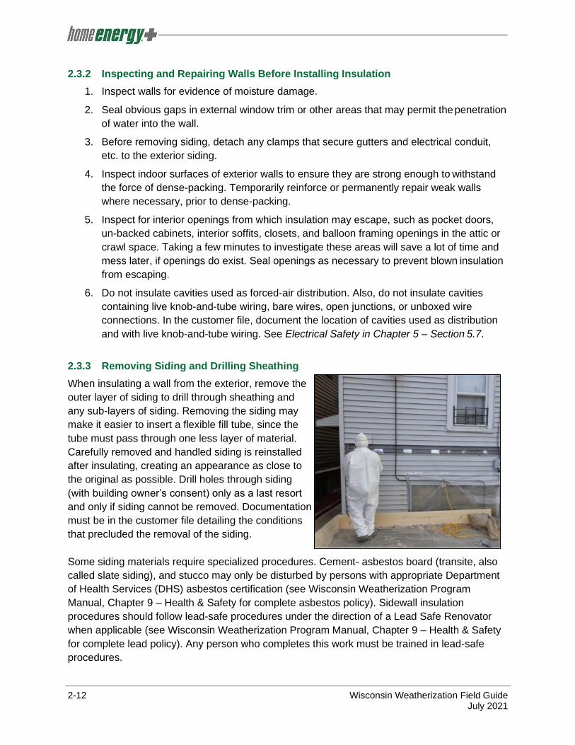
2.3.3 Removing Siding and Drilling Sheathing
When insulating a wall from the exterior, remove the
outer layer of siding to drill through sheathing and
any sub-layers of siding. Removing the siding may
make it easier to insert a flexible fill tube, since the
tube must pass through one less layer of material.
Carefully removed and handled siding is reinstalled
after insulating, creating an appearance as close to
the original as possible. Drill holes through siding
(with building owner’s consent) only as a last resort
and only if siding cannot be removed. Documentation
must be in the customer file detailing the conditions
that precluded the removal of the siding.
Some siding materials require specialized procedures. Cement- asbestos board (transite, also
called slate siding), and stucco may only be disturbed by persons with appropriate Department
of Health Services (DHS) asbestos certification (see Wisconsin Weatherization Program
Manual, Chapter 9 – Health & Safety for complete asbestos policy). Sidewall insulation
procedures should follow lead-safe procedures under the direction of a Lead Safe Renovator
when applicable (see Wisconsin Weatherization Program Manual, Chapter 9 – Health & Safety
for complete lead policy). Any person who completes this work must be trained in lead-safe
procedures.

Wisconsin Weatherization Field Guide 2-13 July 2021
1. Metal or vinyl siding may be removed with a zip tool.
2. Lap siding requires careful prying with a flat bar
underneath the nails that fasten the siding to the
framing. Cut the paint between pieces of siding with a
utility knife before prying.
For more information regarding siding removal, refer to
“Dense-Pack Sidewall Insulation” video, available on the HE
Plus TTA website.
2.3.4 Dense-Packed Wall Insulation from the Exterior
Dense-packed wall insulation is best installed using the tube
method with an insulation blower equipped with separate controls for air and material feed. Mark
the fill tube in one-foot intervals so the installer knows when the tube has reached the top of the
wall cavity and when the end of the tube is almost removed upon completion of dense-packing
the cavity.
To prevent settling, loose-fill insulation must be blown at the
recommended density of 3.5 to 4.5 pounds per cubic foot for
cellulose and 2.0 to 2.5 pounds per cubic foot for fiberglass.
To insulate sidewalls from the exterior:
1. Remove siding, following lead-safe practices if
required. See Lead Paint and Lead-safe Work in
Chapter 5 – Section 5.5. Transite (slate) siding shall
be removed intact only by persons with appropriate
DHS asbestos certification, unless the siding has
been tested and does not contain asbestos.
2. Drill or cut a two- to three-inch diameter hole to
access each cavity to be insulated.
3. Probe all wall cavities through holes, to identify fire
blocking, diagonal bracing, and other obstacles. After
probing, drill or cut whatever additional holes are
necessary to ensure complete coverage.
Insulation hoses, fittings, and the fill tube: Gradual reductions in the hose diameter will reduce the chance of plugging the hose with insulation. The goal is to achieve a material to air mixture that maximizes production and correct density.
Tube-filling walls: This method can be accomplished from inside or outside the home. It is the preferred wall insulation method because it is a reliable way to achieve a uniform coverage and density.
Removing metal or vinyl siding: A zip tool separates joints in vinyl and metal siding.

2-14 Wisconsin Weatherization Field Guide July 2021
4. Start by insulating several full-height, unobstructed wall
cavities with a known quantity of insulation so the installed
density can be calculated and the blower controls can be
set properly.
5. Depending on the location of the hole, insert the tube all the
way to one end of the cavity. Start the machine and back
the hose out slowly as the cavity fills. Work the hose back
and forth in the cavity to pack the insulation tighter, if
necessary.
6. Shut off the flow of material when approximately one foot
of tube is remaining in the wall. Re-insert the tube to the
opposite end of the cavity, and repeat Step 5. Shut off the
flow of material when the cavity is completely full.
7. Plug the holes, seal the plugs to prevent water and air infiltration, and replace the siding.
When insulating balloon framed walls or the band joist areas on
multi-story buildings, insulate the perimeter between the two floors
by blowing insulation into each floor cavity to create an insulation
plug. This technique also prevents air movement through the floor
cavity.
If the process is requiring too much insulation, use the Bag
Method. See Method A in Chapter 2 ̶ Section 2.2.7 for
information about the Bag Method.
2.3.5 Dense-Packed Wall Insulation from the Interior
In homes where the walls cannot be insulated from the exterior,
insulating from the interior may be necessary. Holes drilled for
insulation must be returned to an appearance as close to original
as possible, or so the result is satisfactory to the customer.
To insulate sidewalls from the interior:
1. Practice lead-safe work techniques. See Lead Paint and Lead-safe Work in Chapter 5 –
Section 5.5.
2. When testing results require, follow asbestos protocols. See Chapter 9 (Health & Safety)
of the Wisconsin Weatherization Program Manual for comprehensive asbestos policies.
3. Remove the baseboard or chair rail when possible to allow drilling. Use wood or foam
plugs and joint compound or quick-setting plaster to seal the holes before re-installing
the baseboard or chair rail. Or, drill holes and stagger them by at least six inches up and
down, which will reduce horizontal cracking in lath-and-plaster walls.
4. Use a non-conductive probe to determine where to drill into the next cavity.
Tube-filling walls: Insulation is dense-packed into walls using a fill tube inserted into the wall cavity.
Plugging a balloon framed floor cavity: Blow a plug of insulation into balloon framed
second-floor cavities.
bag

Wisconsin Weatherization Field Guide 2-15 July 2021
5. Insert a fill tube, and dense-pack the cavity following the procedures detailed in Dense-
Packed Wall Insulation from the Exterior in Chapter 2 - Section 2.3.4.
6. Use wood or foam plugs along with joint compound or quick-setting plaster to seal and
patch the holes.
7. Chair rail or wallpaper trim can be installed to conceal the holes if necessary.
2.3.6 Dense-Packing from Other Access Locations
Balloon framed cavities can often be insulated from either the attic or basement where the
cavity is open. In these cases, use a temporary dam to completely fill the cavity with dense-
packed insulation, following the procedures described in Installing Attic Insulation in 1½-Story
Homes (Finished Attics) in Chapter 2 – Section 2.2.7.
2.3.7 Interior Open-Cavity Wall Insulation
Fiberglass batts achieve their rated R-value only when
installed correctly. If gaps exist between the cavity and batt
at the top and bottom, or if the batt is compressed, the
effective R-value can decrease by as much as 30 percent.
Fiberglass insulation must have a flame spread and smoke
development index of 24/450 or less and backing material
with a smoke development index of 450 or less when tested
in accordance with ASTM E84 or UL 723.
To insulate open interior-wall cavities:
1. Prior to installing insulation, air seal the exterior wall
sheathing.
2. Use appropriately sized, unfaced friction-fit fiberglass batt insulation where possible.
3. Choose high-density batts whenever possible and install to the maximum structurally
allowable.
4. Install the batt to fill the entire cavity, without spaces
at the corners or edges.
5. Cut batt insulation to the exact height of the cavity. A
short batt creates air spaces above and beneath the
batt, allowing convection. A long batt bunches up,
creating air pockets.
6. Split batts around wiring, rather than letting the wiring
bunch the batt to one side of the cavity.
7. Insulate behind and around obstacles with scrap
pieces of batt.
8. Prior to installing drywall, cover exposed unfaced insulation with an airtight polyethylene
vapor retarder. Install the vapor retarder to the warm side of the wall.
Batt split around a cable: The batt attains its rated R- value.
Fiberglass batts compressed by a cable: This reduces the wall’s R-value by creating a void between the insulation and interior wallboard.

2-16 Wisconsin Weatherization Field Guide July 2021
9. Kraft- or foil-faced insulation exposed to the interior living space must be covered with a
thermal barrier such as a minimum half-inch gypsum board.
Dense-packed insulation may sometimes be blown into open stud cavities through an air barrier
or plastic mesh. This is a good option if the insulation is packed densely enough to resist
settling. The mesh will bulge if installed at the proper density; however, it could hinder drywall
installation. Instead, consider cutting holes in the drywall to tube-fill the cavities with dense-
packed insulation after installing drywall.
2.4 Crawl Space Requirements
Crawl spaces are usually small and difficult areas to complete work. Agencies should have a
written policy for the minimum working requirements to effectively complete the necessary work
in a crawl space.
2.4.1 Crawl Space Access Requirements
When creating new access to a crawl space, the following access sizing guide should be
implemented:
Access Type Size
Floor access 18" x 24"
Perimeter wall access 16" x 24"
A new access may need to be smaller if the existing framing members constrain work. Do not
disturb framing or structural systems to install the access hatch.
2.4.2 Crawl Space Signage
A laminated sign, at least 8½" x 11" in size, should be posted at every access, inside of the
crawl space. The sign will include the following information:
✓ List of mechanical components installed in the crawl space.
✓ Statement prohibiting the storage of hazardous and flammable materials.
✓ Caution statement for those entering the crawl space not to damage the air barrier,
ground vapor retarder, and/or insulation.
✓ Installer contact information will be included on the sign in case there are questions or
need for repairs.
2.5 Floor and Foundation Insulation
Insulation and air sealing of the foundation combine to complete the thermal boundary at the
base of the building. As parts of the foundation are identified and defined as inside of the
thermal and pressure boundaries, it is very important to ensure exposed soil is covered with a
ground vapor retarder. Assess the crawl space ground area for health and safety issues and
debris. Remove any vegetation or items greater than one inch that might penetrate through the
ground vapor retarder or cause injury. Properly dispose of any identified items.

Wisconsin Weatherization Field Guide 2-17 July 2021
Install a ground vapor retarder in accordance with the SWS section 2.0202 (minimum 6 mil in
thickness of 0.1 perm or less) over exposed earth. Install a thicker ground vapor retarder if items
are present in the crawl space that could reduce the effectiveness and durability of the barrier.
Overlap the seams of the ground vapor retarder a minimum of 12 inches with a “reverse
shingle” or “upslope lapping” technique (e.g., overlapping so water leaking through the
foundation wall will not flow in between the seams). Seal all seams, and around all penetrations.
Install the wall vapor retarder under the ground vapor retarder at the wall to floor connection.
The air barrier and ground vapor retarder should not interfere with the established drainage
pattern. Interior drainage collection points must remain accessible. Secure the ground vapor
retarder with fasteners or ballasts on sloping ground or if the area is routinely used for
maintenance or storage to avoid uplift. All penetrations in the ground vapor retarder along with
seams and connections to the foundation must be sealed with a durable and compatible
sealant.
Ensure the ground vapor retarder is not damaged when installed or when performing work. Seal
holes and rips with the appropriate materials if it is damaged in the work process.
If an existing drain is present, the installed ground vapor retarder should not prevent flow of
moisture to the drain.
The choice between insulating the floor or the foundation should be made based on accessibility
and if heating distribution or plumbing runs through the area. Basements are generally not
insulated during weatherization, but sealing is typically required to stop air infiltration. For other
considerations, see Locating the Pressure/Thermal Boundary in Chapter 1 – Section 1.5.3.
2.5.1 Establishing a Thermal Boundary
To establish an effective thermal boundary, the insulation and air barrier should be adjacent to
each other, with the air barrier located between the insulation and the conditioned space.
In most northern climates, the preferred method is to insulate and air seal the foundation walls
and not the floor. This includes sealing crawl space vents. This strategy encloses the furnace,
ducts, pipes, and other features within the thermal and pressure boundaries.
2.5.2 Rim Joist and Box Sill Insulation
The joist spaces at the perimeter of the floor can be a weak point in the thermal boundary.
Insulating both the rim joist and longitudinal box joist are appropriate either as individual
procedures or as part of floor or foundation insulation.
Air seal stud cavities in balloon framed homes as a part of insulating the rim joist. If the box sill
will be insulated, two-part foam can be useful as it insulates and air seals in one application.
One primary advantage of two-part foam is its ease of installation in areas of limited
accessibility. Follow the foam manufacturer’s installation instructions and applicable building

2-18 Wisconsin Weatherization Field Guide July 2021
codes when installing two-part foam. Before
applying spray foam, ensure the substrate is
dry and reasonably clean. Do not apply more
than 3 inches of spray foam in the box sill area.
Two-part spray foam shall be installed at a
density of 0.5 – 2.0 lb/ft3. SPF installed below
the sill box requires a thermal barrier from the
interior of the dwelling.
Use appropriate personal protective equipment
(PPE) when installing two-part foam. Follow the
manufacturer recommendations for safety
precautions. See Personal Protective
Equipment in Chapter 5 – Section 5.1 and the General Information on Spray Polyurethane
Foam (SPF) Appendix A-4 for additional information.
Rigid board insulation is also good for insulating and air sealing the rim joist area. If foam board
is used to insulate the rim, spray foam can be used to seal around the edges. Longitudinal box
joist cavities, enclosed by a floor joist, may be sealed and blown with wall insulation unless
there is evidence of a moisture problem in the area. If the insulation will be in direct contact with
the foundation, cellulose insulation should not be used to prevent potential moisture issues.
Use faced fiberglass batt insulation with caution. Air can circulate around the fiberglass, causing
condensation and encouraging mold on the cold rim joist. Fiberglass batts may be used to
insulate the rim joist only when:
1. The box sill is effectively air sealed.
2. The batts are cut to the proper size and completely fill the cavity.
2.5.3 Floor Insulation
Prior to insulating the floor, take all appropriate measures to establish an effective air barrier at
the floor, in order to prevent air from passing through or around floor insulation.
Insulating Open Floor Cavities
Install a ground vapor retarder that runs up the
foundation walls at least six inches in crawl spaces.
Seal the ground vapor retarder to the foundation wall
with appropriate material and seal all penetrations.
Caution: Vapor retarders are typically for use in crawl
spaces. In basements, restrict their use to basements
with dirt floors and limited access. If the ground vapor
retarder is installed in a seldom-used basement, install
walk boards to prevent residents from slipping.
Insulating and air sealing rim joist: Rigid board insulation installed in joist cavities, with spray foam to seal at the edges.

Wisconsin Weatherization Field Guide 2-19 July 2021
Problems such as plumbing leaks or bad site drainage must be addressed prior to installing the
barrier, to avoid water pooling on or under the barrier.
Complete the following when insulating open floor cavities:
1. If the walls are balloon framed, contain wall insulation by air sealing the bottoms of the
stud cavities prior to installing floor insulation.
2. Install the maximum thickness of insulation between floor joists that the structure allows.
Fill the entire joist space if possible. Fit floor insulation tightly against the subfloor and
the rim joist to reduce air convection.
3. Install insulation without voids, edge gaps, or end gaps. Fit insulation closely around
cross bracing and other obstructions.
4. Securely support batt insulation within each cavity with insulation hangers, plastic mesh,
a vapor-permeable air barrier, or other supporting material.
5. Seal and insulate ducts remaining in the crawl space or unoccupied basement. See
Forced-Air Furnace Air Distribution in Chapter 3 – Section 3.4 for information on sealing
and insulating ductwork.
6. Consider installing a vapor-permeable air barrier to prevent convective looping, support
the insulation, and keep pests out.
Insulating Enclosed Floor Cavities Install dense-pack insulation in floor cavities. Confirm the cavities are enclosed by rigid
sheeting. This method works well in garage ceilings, cantilevered floors, and beneath bay
windows.
2.5.4 Foundation Insulation
Foundation insulation is usually installed on the inside of the foundation wall. Less frequently,
foundation insulation is applied from the home’s exterior. Where termite pressure may exist,
removable band joist insulation will be installed.
Blowing a garage floor cavity: Uninsulated floor cavities can be insulated with blown fiberglass or cellulose insulation, using a fill tube.

2-20 Wisconsin Weatherization Field Guide July 2021
Interior Foundation Insulation
1. Attach insulation to the inside wall surface with
appropriate fasteners and/or adhesive. Install
insulation with no significant voids or edge gaps.
2. Foil Scrim Kraft (FSK) fiberglass insulation
should be attached to the sill plate, floor joists,
and/or floor. Insulate the rim joists with unfaced
fiberglass before installing the FSK-faced
insulation to prevent a void behind the FSK
insulation at the rim joist.
3. Securely attach extruded or expanded
polystyrene or foil-faced polyisocyanurate
insulation boards when installed on flat foundation walls.
4. Spray two-part foam on the interior surface of the foundation to maintain the required
insulation level. This may require application of more than one coat to ensure full curing
of the material. Take proper precautions for the safety of the crews and occupants
during installation. Follow the manufacturer’s recommendations for application and for
safety equipment to be used. Follow all applicable building codes. When applied
correctly, two-part foam will insulate and air seal the foundation. Typically, two-part foam
expands to twice the thickness of the initial application, so be careful not to over-
insulate. See the General Information on Spray Polyurethane Foam (SPF) in Appendix
A-4 for additional information.
Fiberglass foundation insulation: Use this method only in dry conditions where the drainage outdoors is effective.
Two-part foam sprayed on rubble masonry: Rubble masonry walls can be insulated on the interior with sprayed foam.
Foam-insulated crawl space: Two-part foam insulates and seals the rim joist as well as insulating the foundation walls.

Wisconsin Weatherization Field Guide 2-21 July 2021
5. In cold weather, apply a skim-coat of foam first, before fully spraying the wall. The skim-
coat will heat up the wall, which will help the foam adhere to the wall.
6. When two-part foam is used, a thermal barrier is required to separate the foam plastic
from the living area. Thermal barriers can be applied to a wall that separates crawl
space insulation from a basement. For buildings with only a crawl space, the plywood
flooring serves as the separation.
7. Attach outside access hatches securely to the foundation wall, latched and weather-
stripped. The hatch should be lockable. Insulate the hatch only when it is part of the
thermal boundary.
Exterior Foundation Insulation
1. Install exterior foam insulation to a minimum depth of six inches below grade, unless
restricted by non-excavatable ground, such as a sidewalk. Apply a durable covering or
coating to the entire surface of the insulation, including joints and corners.
2. Completely cover the exposed foundation with insulation.
3. All connecting joints must form a seal or be sealed with appropriate sealant.
4. If the insulation is not protected by the siding, install a drip edge.

2-22 Wisconsin Weatherization Field Guide July 2021
Final Inspection and Quality Assurance Standards
Acceptable installations shall meet the following standards.
Attic Insulation
Attic Insulation Storage Area
1. The storage area is as small as possible and still meets the homeowner’s needs.
2. Floor plugs installed if needed.
3. The insulation installed beneath the storage area is installed to the R-value specified by
the computerized energy audit.
4. The storage area presents no hazards to occupant.
5. Items in the storage area were protected from insulation.
6. Floorboards were re-installed properly.
Damming and Boxing
1. The dam is higher than the surrounding insulation and does not interfere with opening
the access.
2. The dam is effective in performing its specified function.
3. When necessary, the dam is constructed of non-combustible material.
4. The chimney dam is at least three inches from an active chimney or per manufacturer’s
instructions.
5. Active chimneys meet chimney guidelines (e.g., no cracking, no creosote present,
structurally sound, etc.).
Attic Access
1. Allows for repeated access to attic.
2. All trim is properly sealed and weather-stripped.
3. Access panel is insulated to same R-value as the attic or the maximum structurally
allowable, whichever is lower.
4. Access is covered with an appropriate fire rated material (as required by code).
5. Insulation certificate is completed and placed near an attic hatch or in another visible
location such as near an electrical panel.
Attic Bypass Sealing
1. Bypasses are sealed to the level called for under Wisconsin’s Weatherization Program
requirements.
2. Bypasses are sealed with an appropriate material and amount of material.
3. All equipment mounted in the ceiling is properly air sealed.

Wisconsin Weatherization Field Guide 2-23 July 2021
Roof Leaks
1. No visible evidence of roof leaking is present.
Attic Wiring
1. All electrical boxes are covered, sealed, and flagged if concealed by insulation.
2. All live knob-and-tube wiring is boxed out prior to insulation, the boxing ends are sealed,
and the boxing is flagged.
3. Rewired (permit pulled, if applicable) and inspected (if required).
Heat Producing Products (lights, chimneys, flues, attic furnaces, and non-IC rate
fixtures)
1. Boxing is a minimum of three inches from device. Boxing material is gypsum wallboard,
cement board, or other code-approved material.
Exhaust Fans and Vent Stacks
1. Vents will exhaust the specified area to the outdoors.
2. Stacks are properly sealed at intersection with building materials.
Attic Vapor Retarders
1. Installed correctly toward the warm side.
2. Installed in continuous manner, with edges sealed.
Attic Venting
1. Allows air to pass through vent.
2. 40-50% of installed vents are within 3 feet of the highest point in the vented space.
3. Vents are made of corrosion-resistant material appropriate for their specific location.
4. Vents have screens with non-corroding wire mesh with openings of 1/16" to ¼" to prevent
pest entry (e.g., birds, bats, and bees).
Attic Floor Insulation, Open Blow
1. Installed to the R-value selected by the audit.
2. Insulation is installed to a uniform R-value, with no variances of greater than two inches.
3. All wiring is properly flagged, no bare wiring, junction boxes have covers.
4. Live knob-and-tube wiring is properly dammed, maintaining 3 inch clearance to
insulation.
5. Insulation depth markers are in place.

2-24 Wisconsin Weatherization Field Guide July 2021
Attic Cavities (site-built)
1. All areas specified are insulated.
Kneewall Attic Walls
1. All cavities are filled with insulation to the maximum structurally allowable, with no voids
present.
2. The vapor permeable air barrier seams and edges are sealed, and it is mechanically
fastened.
Sidewall Insulation (site-built)
1. All cavities are properly insulated to the maximum allowable amount and proper density.
When cavities are dense-packed to reduce air leakage, artificial smoke does not move
through penetrations when the building is pressurized to 50 pascals.
2. Blown insulation is installed from the exterior or the attic unless limited by the building
structure or health and safety issues, with prior approval of the building owner.
3. Based on file documentation (photos), work has been completed in a lead-safe manner.
4. All siding that is suspect ACM has been addressed under the supervision of a competent
person.
Sidewall Wiring
1. All hazards are addressed prior to insulating.
Floors Over Unheated Areas (site-built including cantilevers)
1. Insulated to the maximum structurally allowable. When cavities are dense-packed to
reduce air leakage, artificial smoke does not move through penetrations when the
building is pressurized to 50 pascals.
2. Vapor-permeable air barriers may be used on the cold side of the insulation.
3. Weather and pest-proof cover between cantilever insulation and the outside.
Box Sill Insulation
1. Area is sealed and filled to the R-value selected by the audit.
Interior Foundation Insulation
1. Area is insulated to the R-value selected by the audit.
2. If two-part foam is installed, there must be a thermal barrier between the area of
application and living area of the building, including in unintentionally heated basements.
3. Continuous ground vapor retarder covers all exposed soil surfaces and is sealed to the
wall. A minimum of a 12-inch overlap of seams is maintained using the reverse or
upslope lapping technique. The ground vapor retarder is fastened down using durable

Wisconsin Weatherization Field Guide 2-25 July 2021
fasteners or ballasts in areas routinely used for maintenance or storage or where sloping
ground exists to avoid uplift. All seams, penetrations, and connections to the foundation
are sealed with a durable, compatible sealant.
Exterior Foundation Insulation
1. A minimum of R-5 insulation installed.
2. NEAT documentation in the file.
3. Depth of the insulation is at least six inches and not greater than 14 inches.
4. Material has protective coating at least six inches below grade.
5. An effective drip edge makes a positive seal between the foundation and the wall
assembly.