chapter 2 data representation in computer systems
Post on 20-Dec-2015
384 views
TRANSCRIPT
Chapter 2Data Representation in
Computer Systems

2
2.4 Signed Integer Representation
• For example, in 8-bit signed magnitude, positive 3 is:00000011
• Negative 3 is: 10000011• Computers perform arithmetic operations on
signed magnitude numbers in much the same way as humans carry out pencil and paper arithmetic.– Humans often ignore the signs of the operands
while performing a calculation, applying the appropriate sign after the calculation is complete.

3
2.4 Signed Integer Representation
• Binary addition is as easy as it gets. You need to know only four rules:
0 + 0 = 0 0 + 1 = 11 + 0 = 1 1 + 1 = 10
• The simplicity of this system makes it possible for digital circuits to carry out arithmetic operations.– We will describe these circuits in Chapter 3.
Let’s see how the addition rules work with signed magnitude numbers . . .

4
Examples
• A. 3 – 3 or 3 + (-3)• 3 – 00000011• -3 – 11111101 (Two’s complement)• 32 – 18 = 14 -- 32 + (-18)• 32 00100000• +18 = 0001010• 01110101 (One’s complement)• 11110110 (Two’s complement)• Therefore, 00100000 (32)• +11110110 (-18)• 00010110 (14)

5
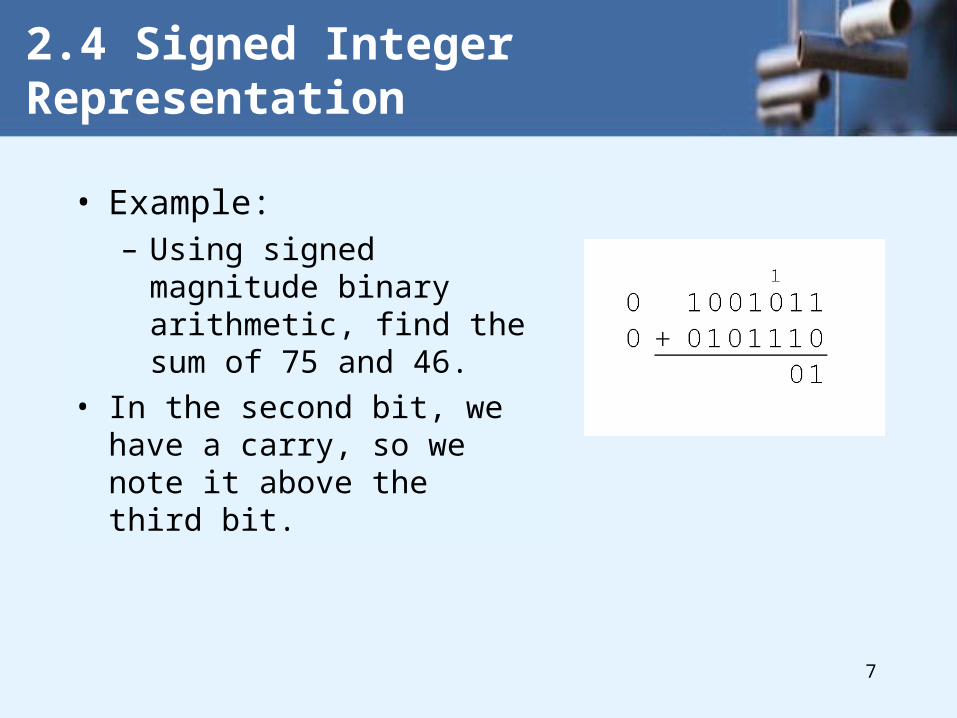
2.4 Signed Integer Representation
• Example:– Using signed magnitude
binary arithmetic, find the sum of 75 and 46.
• First, convert 75 and 46 to binary, and arrange as a sum, but separate the (positive) sign bits from the magnitude bits.

6
2.4 Signed Integer Representation
• Example:– Using signed magnitude
binary arithmetic, find the sum of 75 and 46.
• Just as in decimal arithmetic, we find the sum starting with the rightmost bit and work left.
7
2.4 Signed Integer Representation
• Example:– Using signed magnitude
binary arithmetic, find the sum of 75 and 46.
• In the second bit, we have a carry, so we note it above the third bit.
8
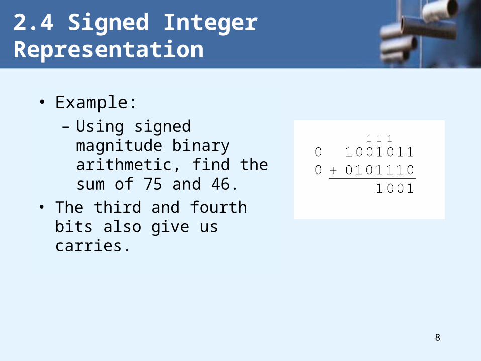
2.4 Signed Integer Representation
• Example:– Using signed magnitude
binary arithmetic, find the sum of 75 and 46.
• The third and fourth bits also give us carries.

9
2.4 Signed Integer Representation
• Example:– Using signed magnitude binary
arithmetic, find the sum of 75 and 46.
• Once we have worked our way through all eight bits, we are done.
In this example, we were careful careful to pick two values whose sum would fit into seven bits. If that is not the case, we have a problem.
10
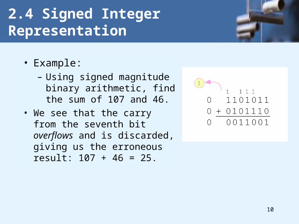
2.4 Signed Integer Representation
• Example:– Using signed magnitude binary
arithmetic, find the sum of 107 and 46.
• We see that the carry from the seventh bit overflows and is discarded, giving us the erroneous result: 107 + 46 = 25.

11
2.4 Signed Integer Representation
• Signed magnitude representation is easy for people to understand, but it requires complicated computer hardware.
• Another disadvantage of signed magnitude is that it allows two different representations for zero: positive zero and negative zero.
• For these reasons (among others) computers systems employ complement systems for numeric value representation.

12
2.4 Signed Integer Representation
• In complement systems, negative values are represented by some difference between a number and its base.
• In diminished radix complement systems, a negative value is given by the difference between the absolute value of a number and one less than its base.
• In the binary system, this gives us one’s complement. It amounts to little more than flipping the bits of a binary number.
13
2.4 Signed Integer Representation
• For example, in 8-bit one’s complement, positive 3 is: 00000011
• Negative 3 is: 11111100– In one’s complement, as with signed magnitude,
negative values are indicated by a 1 in the high order bit.• Complement systems are useful because they
eliminate the need for special circuitry for subtraction. The difference of two values is found by adding the minuend to the complement of the subtrahend.

14
2.4 Signed Integer Representation
• With one’s complement addition, the carry bit is “carried around” and added to the sum.– Example: Using one’s
complement binary arithmetic, find the sum of 48 and - 19
We note that 19 in one’s complement is 00010011,
so -19 in one’s complement is: 11101100.

15
2.4 Signed Integer Representation
• Although the “end carry around” adds some complexity, one’s complement is simpler to implement than signed magnitude.
• But it still has the disadvantage of having two different representations for zero: positive zero and negative zero.
• Two’s complement solves this problem.
• Two’s complement is the radix complement of the binary numbering system.

16
2.4 Signed Integer Representation
• To express a value in two’s complement:– If the number is positive, just convert it to binary and
you’re done.
– If the number is negative, find the one’s complement of the number and then add 1.
• Example: – In 8-bit one’s complement, positive 3 is: 00000011– Negative 3 in one’s complement is: 11111100– Adding 1 gives us -3 in two’s complement form: 11111101.
17
2.4 Signed Integer Representation
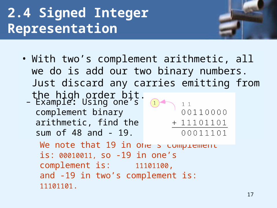
• With two’s complement arithmetic, all we do is add our two binary numbers. Just discard any carries emitting from the high order bit.
We note that 19 in one’s complement is: 00010011,
so -19 in one’s complement is: 11101100,and -19 in two’s complement is: 11101101.
– Example: Using one’s complement binary arithmetic, find the sum of 48 and - 19.
18
2.4 Signed Integer Representation
• When we use any finite number of bits to represent a number, we always run the risk of the result of our calculations becoming too large to be stored in the computer.
• While we can’t always prevent overflow, we can always detect overflow.
• In complement arithmetic, an overflow condition is easy to detect.

19
2.4 Signed Integer Representation
• Example:– Using two’s complement binary
arithmetic, find the sum of 107 and 46.
• We see that the nonzero carry from the seventh bit overflows into the sign bit, giving us the erroneous result: 107 + 46 = -103.
Rule for detecting two’s complement overflow: When the “carry in” and the “carry out” of the sign bit differ, overflow has occurred.

20
Principles of Floating Number• 1. Purpose• To express a large range of numbers• A small number: the mass of the electron• 0.0000000000000000000000000009 grams
• A large number: the mass of the sun• 2000000000000000000000000000000000 g
• Total 32 zeros• The range exceeding 10E60
Total 27 zeros

21
IEEE Floating-Point Standard 754• Until 1980, each computer manufacturer
had its own floating-point format.
• In 1985, IEEE Standard 754 was born.
• Most CPUs these days (including the Intel, Sun Micros’ SPARC and JVM) conform this standard.
•
22
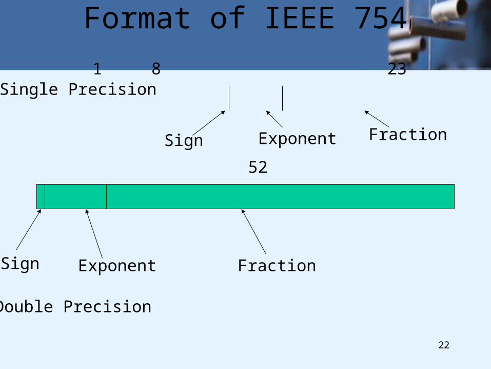
Format of IEEE 754
Sign Exponent Fraction
Sign Exponent Fraction
1 8 23 (Bits)
1 11 52 (Bits)
Single Precision
Double Precision

23
Implied 1, binary point and Fraction
• Conventional fraction in floating-point
. 1 The rest of the fraction
.The IEEE 754
We called this fraction as “significand”1.Implied 1 & an implied binary point 23 or 52 bits

24
Slide 22 of 28

25
Denormalized Numbers in IEEE 754• Previously--- Either set it (a number smaller
than it can be expressed) to zero or cause a floating-point underflow trap.
• For the numbers large than than the system can expressed----Overflow
• Now---IEEE 754 introduced the denormalized numbers

26
The smallest number and the largest number
• The smallest number:
• -150 (-23+(-127))2
The largest number: 2150
Two zeros are present in this scheme: Positive zero and negative zero both havean exponent zero and fraction zero & theImplied 1 before implied binary point becomes 0. It will follow all the math rules About infinity.NoN (not a number) to express I/I

27
2.5 Floating-Point Representation
• The signed magnitude, one’s complement, and two’s complement representation that we have just presented deal with integer values only.
• Without modification, these formats are not useful in scientific or business applications that deal with real number values.
• Floating-point representation solves this problem.

28
2.5 Floating-Point Representation
• If we are clever programmers, we can perform floating-point calculations using any integer format.
• This is called floating-point emulation, because floating point values aren’t stored as such, we just create programs that make it seem as if floating-point values are being used.
• Most of today’s computers are equipped with specialized hardware that performs floating-point arithmetic with no special programming required.

29
2.5 Floating-Point Representation
• Floating-point numbers allow an arbitrary number of decimal places to the right of the decimal point.– For example: 0.5 0.25 = 0.125
• They are often expressed in scientific notation. – For example:
0.125 = 1.25 10-1
5,000,000 = 5.0 106

30
2.5 Floating-Point Representation
• Computers use a form of scientific notation for floating-point representation
• Numbers written in scientific notation have three components:
31
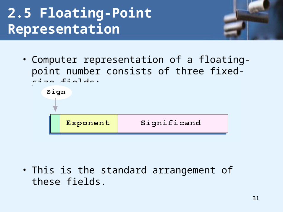
• Computer representation of a floating-point number consists of three fixed-size fields:
• This is the standard arrangement of these fields.
2.5 Floating-Point Representation

32
• The one-bit sign field is the sign of the stored value.
• The size of the exponent field, determines the range of values that can be represented.
• The size of the significand determines the precision of the representation.
2.5 Floating-Point Representation

33
• The IEEE-754 single precision floating point standard uses an 8-bit exponent and a 23-bit significand.
• The IEEE-754 double precision standard uses an 11-bit exponent and a 52-bit significand.
2.5 Floating-Point Representation
For illustrative purposes, we will use a 14-bit model with a 5-bit exponent and an 8-bit significand.

34
• The significand of a floating-point number is always preceded by an implied binary point.
• Thus, the significand always contains a fractional binary value.
• The exponent indicates the power of 2 to which the significand is raised.
2.5 Floating-Point Representation
35
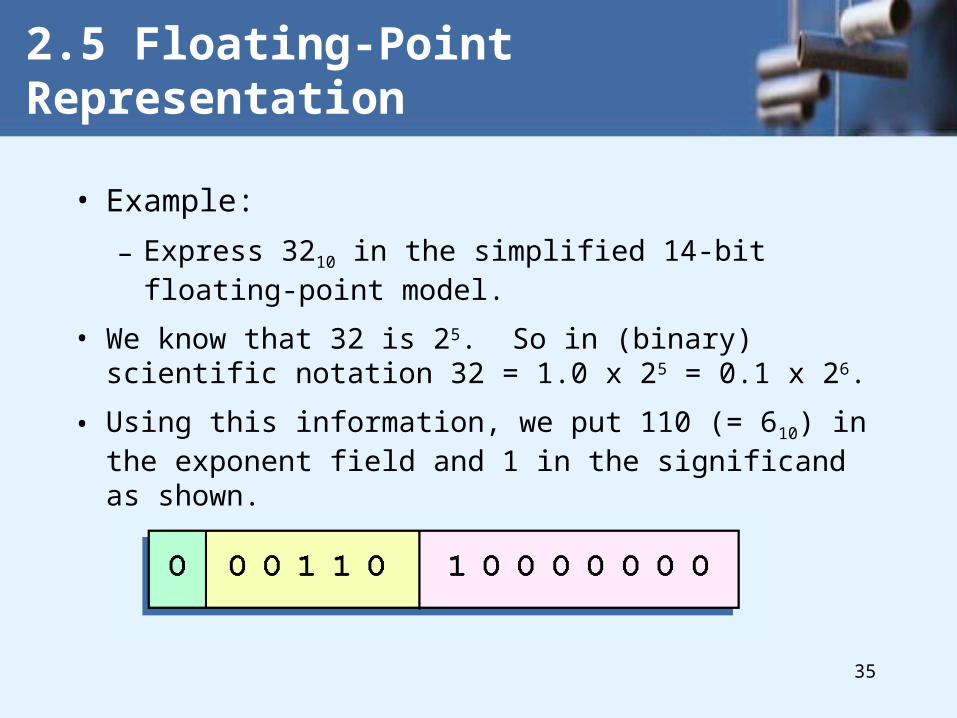
• Example:
– Express 3210 in the simplified 14-bit floating-point model.
• We know that 32 is 25. So in (binary) scientific notation 32 = 1.0 x 25 = 0.1 x 26.
• Using this information, we put 110 (= 610) in the exponent field and 1 in the significand as shown.
2.5 Floating-Point Representation

36
• The illustrations shown at the right are all equivalent representations for 32 using our simplified model.
• Not only do these synonymous representations waste space, but they can also cause confusion.
2.5 Floating-Point Representation

37
• Another problem with our system is that we have made no allowances for negative exponents. We have no way to express 0.5 (=2 -1)! (Notice that there is no sign in the exponent field!)
2.5 Floating-Point Representation
All of these problems can be fixed with no changes to our basic model.

38
• To resolve the problem of synonymous forms, we will establish a rule that the first digit of the significand must be 1. This results in a unique pattern for each floating-point number.– In the IEEE-754 standard, this 1 is implied meaning
that a 1 is assumed after the binary point.
– By using an implied 1, we increase the precision of the representation by a power of two. (Why?)
2.5 Floating-Point Representation
In our simple instructional model, we will use no implied bits.

39
• To provide for negative exponents, we will use a biased exponent.
• A bias is a number that is approximately midway in the range of values expressible by the exponent. We subtract the bias from the value in the exponent to determine its true value.– In our case, we have a 5-bit exponent. We will use 16
for our bias. This is called excess-16 representation.
• In our model, exponent values less than 16 are negative, representing fractional numbers.
2.5 Floating-Point Representation
40
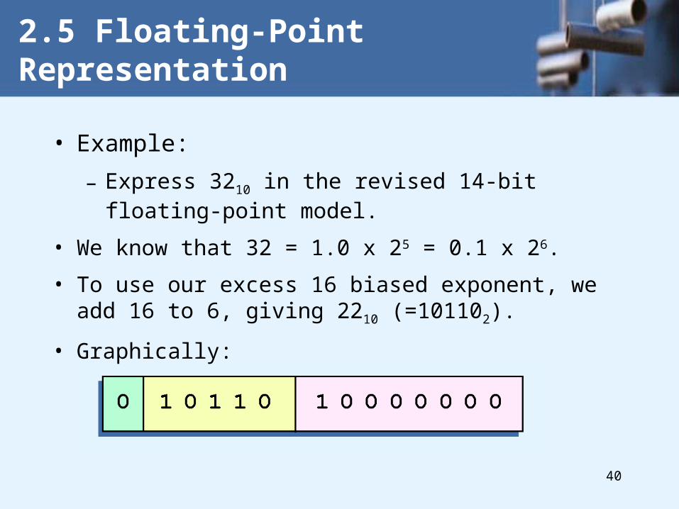
• Example:
– Express 3210 in the revised 14-bit floating-point model.
• We know that 32 = 1.0 x 25 = 0.1 x 26.
• To use our excess 16 biased exponent, we add 16 to 6, giving 2210 (=101102).
• Graphically:
2.5 Floating-Point Representation

41
• Example:– Express 0.062510 in the revised 14-bit floating-point
model.
• We know that 0.0625 is 2-4. So in (binary) scientific notation 0.0625 = 1.0 x 2-4 = 0.1 x 2 -3.
• To use our excess 16 biased exponent, we add 16 to -3, giving 1310 (=011012).
2.5 Floating-Point Representation

42
• Example:– Express -26.62510 in the revised 14-bit floating-point
model.
• We find 26.62510 = 11010.1012. Normalizing, we have: 26.62510 = 0.11010101 x 2 5.
• To use our excess 16 biased exponent, we add 16 to 5, giving 2110 (=101012). We also need a 1 in the sign bit.
2.5 Floating-Point Representation
43
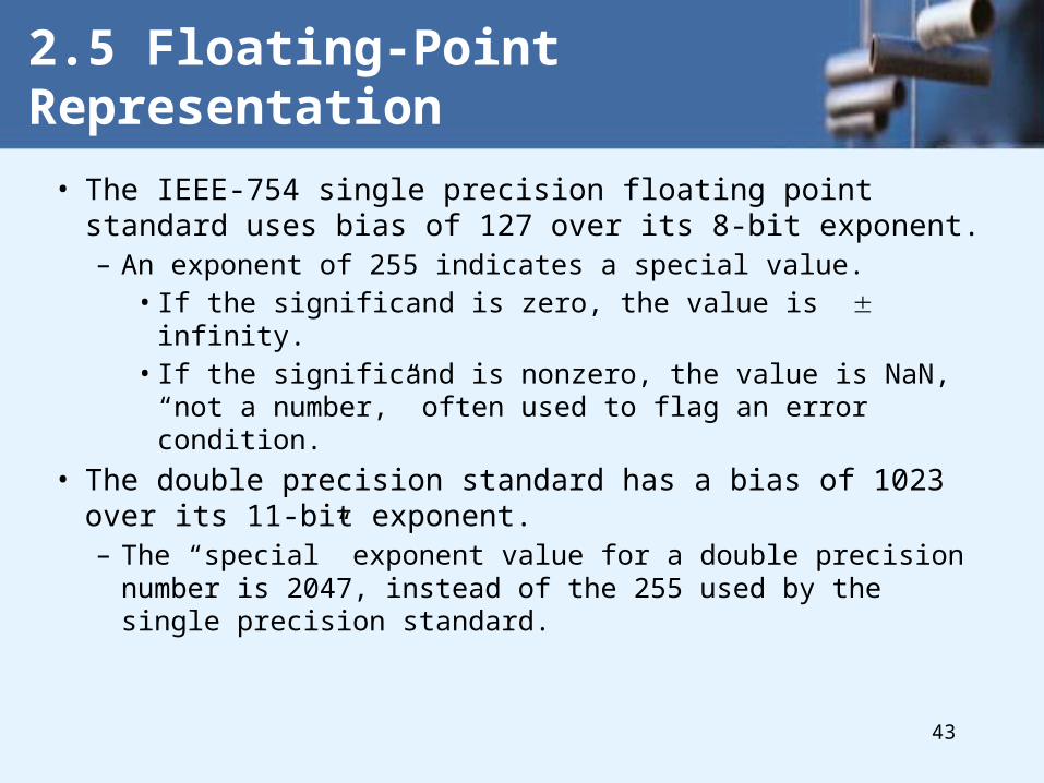
• The IEEE-754 single precision floating point standard uses bias of 127 over its 8-bit exponent. – An exponent of 255 indicates a special value.
• If the significand is zero, the value is infinity.• If the significand is nonzero, the value is NaN, “not a
number,” often used to flag an error condition.
• The double precision standard has a bias of 1023 over its 11-bit exponent.– The “special” exponent value for a double precision number
is 2047, instead of the 255 used by the single precision standard.
2.5 Floating-Point Representation
44
• Both the 14-bit model that we have presented and the IEEE-754 floating point standard allow two representations for zero.
– Zero is indicated by all zeros in the exponent and the significand, but the sign bit can be either 0 or 1.
• This is why programmers should avoid testing a floating-point value for equality to zero.
– Negative zero does not equal positive zero.
2.5 Floating-Point Representation

45
• Floating-point addition and subtraction are done using methods analogous to how we perform calculations using pencil and paper.
• The first thing that we do is express both operands in the same exponential power, then add the numbers, preserving the exponent in the sum.
• If the exponent requires adjustment, we do so at the end of the calculation.
2.5 Floating-Point Representation

46
• Example:– Find the sum of 1210 and 1.2510 using the 14-bit floating-
point model.
• We find 1210 = 0.1100 x 2 4. And 1.2510 = 0.101 x 2 1 = 0.000101 x 2 4.
2.5 Floating-Point Representation
• Thus, our sum is 0.110101 x 2 4.

47
• Floating-point multiplication is also carried out in a manner akin to how we perform multiplication using pencil and paper.
• We multiply the two operands and add their exponents.
• If the exponent requires adjustment, we do so at the end of the calculation.
2.5 Floating-Point Representation

48
• Example:– Find the product of 1210 and 1.2510 using the 14-bit
floating-point model.
• We find 1210 = 0.1100 x 2 4. And 1.2510 = 0.101 x 2 1.
2.5 Floating-Point Representation
• Thus, our product is 0.0111100 x 2 5 =
0.1111 x 2 4.
• The normalized product requires an exponent of 2010 = 101102.
49
• No matter how many bits we use in a floating-point representation, our model must be finite.
• The real number system is, of course, infinite, so our models can give nothing more than an approximation of a real value.
• At some point, every model breaks down, introducing errors into our calculations.
• By using a greater number of bits in our model, we can reduce these errors, but we can never totally eliminate them.
2.5 Floating-Point Representation
50
• Our job becomes one of reducing error, or at least being aware of the possible magnitude of error in our calculations.
• We must also be aware that errors can compound through repetitive arithmetic operations.
• For example, our 14-bit model cannot exactly represent the decimal value 128.5. In binary, it is 9 bits wide: 10000000.12 = 128.510
2.5 Floating-Point Representation

51
• When we try to express 128.510 in our 14-bit model, we lose the low-order bit, giving a relative error of:
• If we had a procedure that repetitively added 0.5 to 128.5, we would have an error of nearly 2% after only four iterations.
2.5 Floating-Point Representation
128.5 - 128
128
0.39%

52
• Floating-point errors can be reduced when we use operands that are similar in magnitude.
• If we were repetitively adding 0.5 to 128.5, it would have been better to iteratively add 0.5 to itself and then add 128.5 to this sum.
• In this example, the error was caused by loss of the low-order bit.
• Loss of the high-order bit is more problematic.
2.5 Floating-Point Representation

53
• Floating-point overflow and underflow can cause programs to crash.
• Overflow occurs when there is no room to store the high-order bits resulting from a calculation.
• Underflow occurs when a value is too small to store, possibly resulting in division by zero.
2.5 Floating-Point Representation
Experienced programmers know that it’s better for a program to crash than to have it produce incorrect, but plausible, results.

54
• Calculations aren’t useful until their results can be displayed in a manner that is meaningful to people.
• We also need to store the results of calculations, and provide a means for data input.
• Thus, human-understandable characters must be converted to computer-understandable bit patterns using some sort of character encoding scheme.
2.6 Character Codes

55
• As computers have evolved, character codes have evolved.
• Larger computer memories and storage devices permit richer character codes.
• The earliest computer coding systems used six bits.
• Binary-coded decimal (BCD) was one of these early codes. It was used by IBM mainframes in the 1950s and 1960s.
2.6 Character Codes

56
• In 1964, BCD was extended to an 8-bit code, Extended Binary-Coded Decimal Interchange Code (EBCDIC).
• EBCDIC was one of the first widely-used computer codes that supported upper and lowercase alphabetic characters, in addition to special characters, such as punctuation and control characters.
• EBCDIC and BCD are still in use by IBM mainframes today.
2.6 Character Codes

57
• Other computer manufacturers chose the 7-bit ASCII (American Standard Code for Information Interchange) as a replacement for 6-bit codes.
• While BCD and EBCDIC were based upon punched card codes, ASCII was based upon telecommunications (Telex) codes.
• Until recently, ASCII was the dominant character code outside the IBM mainframe world.
2.6 Character Codes

58
• Many of today’s systems embrace Unicode, a 16-bit system that can encode the characters of every language in the world.
– The Java programming language, and some operating systems now use Unicode as their default character code.
• The Unicode codespace is divided into six parts. The first part is for Western alphabet codes, including English, Greek, and Russian.
2.6 Character Codes

59
• The Unicode codes- pace allocation is shown at the right.
• The lowest-numbered Unicode characters comprise the ASCII code.
• The highest provide for user-defined codes.
2.6 Character Codes

60
• When character codes or numeric values are stored in computer memory, their values are unambiguous.
• This is not always the case when data is stored on magnetic disk or transmitted over a distance of more than a few feet.– Owing to the physical irregularities of data storage and
transmission media, bytes can become garbled.
• Data errors are reduced by use of suitable coding methods as well as through the use of various error-detection techniques.
2.7 Codes for Data Recording And Transmission

61
• To transmit data, pulses of “high” and “low” voltage are sent across communications media.
• To store data, changes are induced in the magnetic polarity of the recording medium.
– These polarity changes are called flux reversals.
• The period of time during which a bit is transmitted, or the area of magnetic storage within which a bit is stored is called a bit cell.
2.7 Codes for Data Recording And Transmission

62
• The simplest data recording and transmission code is the non-return-to-zero (NRZ) code.
• NRZ encodes 1 as “high” and 0 as “low.”
• The coding of OK (in ASCII) is shown below.
2.7 Codes for Data Recording And Transmission

63
• The problem with NRZ code is that long strings of zeros and ones cause synchronization loss.
• Non-return-to-zero-invert (NRZI) reduces this synchronization loss by providing a transition (either low-to-high or high-to-low) for each binary 1.
2.7 Codes for Data Recording And Transmission

64
• Although it prevents loss of synchronization over long strings of binary ones, NRZI coding does nothing to prevent synchronization loss within long strings of zeros.
• Manchester coding (also known as phase modulation) prevents this problem by encoding a binary one with an “up” transition and a binary zero with a “down” transition.
2.7 Codes for Data Recording And Transmission

65
• For many years, Manchester code was the dominant transmission code for local area networks.
• It is, however, wasteful of communications capacity because there is a transition on every bit cell.
• A more efficient coding method is based upon the frequency modulation (FM) code. In FM, a transition is provided at each cell boundary. Cells containing binary ones have a mid-cell transition.
2.7 Codes for Data Recording And Transmission

66
• At first glance, FM is worse than Manchester code, because it requires a transition at each cell boundary.
• If we can eliminate some of these transitions, we would have a more economical code.
• Modified FM does just this. It provides a cell boundary transition only when adjacent cells contain zeros.
• An MFM cell containing a binary one has a transition in the middle as in regular FM.
2.7 Codes for Data Recording And Transmission
67
• The main challenge for data recording and trans-mission is how to retain synchronization without chewing up more resources than necessary.
• Run-length-limited, RLL, is a code specifically designed to reduce the number of consecutive ones and zeros.
– Some extra bits are inserted into the code.
– But even with these extra bits RLL is remarkably efficient.
2.7 Codes for Data Recording And Transmission

68
• An RLL(d,k) code dictates a minimum of d and a maximum of k consecutive zeros between any pair of consecutive ones. – RLL(2,7) has been the dominant disk storage coding
method for many years.
• An RLL(2,7) code contains more bit cells than its corresponding ASCII or EBCDIC character.
• However, the coding method allows bit cells to be smaller, thus closer together, than in MFM or any other code.
2.7 Codes for Data Recording And Transmission

69
• The RLL(2,7) coding for OK is shown below, compared to MFM. The RLL code (bottom) contains 25% fewer transitions than the MFM code (top).
2.7 Codes for Data Recording And Transmission
The details as to how this code is derived are given in the text.

70
• It is physically impossible for any data recording or transmission medium to be 100% perfect 100% of the time over its entire expected useful life.
• As more bits are packed onto a square centimeter of disk storage, as communications transmission speeds increase, the likelihood of error increases-- sometimes geometrically.
• Thus, error detection and correction is critical to accurate data transmission, storage and retrieval.
2.8 Error Detection and Correction

71
• Check digits, appended to the end of a long number can provide some protection against data input errors.
– The last character of UPC barcodes and ISBNs are check digits.
• Longer data streams require more economical and sophisticated error detection mechanisms.
• Cyclic redundancy checking (CRC) codes provide error detection for large blocks of data.
2.8 Error Detection and Correction

72
• Checksums and CRCs are examples of systematic error detection.
• In systematic error detection a group of error control bits is appended to the end of the block of transmitted data.– This group of bits is called a syndrome.
• CRCs are polynomials over the modulo 2 arithmetic field.
2.8 Error Detection and Correction
The mathematical theory behind modulo 2 polynomials is beyond our scope. However, we can easily work with it without knowing its theoretical underpinnings.

73
• Modulo 2 arithmetic works like clock arithmetic.
• In clock arithmetic, if we add 2 hours to 11:00, we get 1:00.
• In modulo 2 arithmetic if we add 1 to 1, we get 0. The addition rules couldn’t be simpler:
2.8 Error Detection and Correction
You will fully understand why modulo 2 arithmetic is so handy after you study digital circuits in Chapter 3.
0 + 0 = 0 0 + 1 = 1
1 + 0 = 1 1 + 1 = 0

74
• Find the quotient and remainder when 1111101 is divided by 1101 in modulo 2 arithmetic.
– As with traditional division, we note that the dividend is divisible once by the divisor.
– We place the divisor under the dividend and perform modulo 2 subtraction.
2.8 Error Detection and Correction

75
• Find the quotient and remainder when 1111101 is divided by 1101 in modulo 2 arithmetic…
– Now we bring down the next bit of the dividend.
– We see that 00101 is not divisible by 1101. So we place a zero in the quotient.
2.8 Error Detection and Correction

76
• Find the quotient and remainder when 1111101 is divided by 1101 in modulo 2 arithmetic…
– 1010 is divisible by 1101 in modulo 2.
– We perform the modulo 2 subtraction.
2.8 Error Detection and Correction

77
• Find the quotient and remainder when 1111101 is divided by 1101 in modulo 2 arithmetic…
– We find the quotient is 1011, and the remainder is 0010.
• This procedure is very useful to us in calculating CRC syndromes.
2.8 Error Detection and Correction
Note: The divisor in this example corresponds to a modulo 2 polynomial: X 3 + X 2 + 1.

78
• Suppose we want to transmit the information string: 1111101.
• The receiver and sender decide to use the (arbitrary) polynomial pattern, 1101.
• The information string is shifted left by one position less than the number of positions in the divisor.
• The remainder is found through modulo 2 division (at right) and added to the information string: 1111101000 + 111 = 1111101111.
2.8 Error Detection and Correction

79
• If no bits are lost or corrupted, dividing the received information string by the agreed upon pattern will give a remainder of zero.
• We see this is so in the calculation at the right.
• Real applications use longer polynomials to cover larger information strings.
– Some of the standard poly-nomials are listed in the text.
2.8 Error Detection and Correction

80
• Data transmission errors are easy to fix once an error is detected.
– Just ask the sender to transmit the data again.
• In computer memory and data storage, however, this cannot be done.
– Too often the only copy of something important is in memory or on disk.
• Thus, to provide data integrity over the long term, error correcting codes are required.
2.8 Error Detection and Correction

81
• Hamming codes and Reed-Soloman codes are two important error correcting codes.
• Reed-Soloman codes are particularly useful in correcting burst errors that occur when a series of adjacent bits are damaged.– Because CD-ROMs are easily scratched, they employ a type
of Reed-Soloman error correction.
• Because the mathematics of Hamming codes is much simpler than Reed-Soloman, we discuss Hamming codes in detail.
2.8 Error Detection and Correction

82
• Hamming codes are code words formed by adding redundant check bits, or parity bits, to a data word.
• The Hamming distance between two code words is the number of bits in which two code words differ.
• The minimum Hamming distance for a code is the smallest Hamming distance between all pairs of words in the code.
2.8 Error Detection and Correction
This pair of bytes has a Hamming distance of 3:
83
• The minimum Hamming distance for a code, D(min), determines its error detecting and error correcting capability.
• For any code word, X, to be interpreted as a different valid code word, Y, at least D(min) single-bit errors must occur in X.
• Thus, to detect k (or fewer) single-bit errors, the code must have a Hamming distance of D(min) = k + 1.
2.8 Error Detection and Correction

84
• Hamming codes can detect D(min) - 1 errors
and correct errors
• Thus, a Hamming distance of 2k + 1 is required to be able to correct k errors in any data word.
• Hamming distance is provided by adding a suitable number of parity bits to a data word.
2.8 Error Detection and Correction

85
• Suppose we have a set of n-bit code words consisting of m data bits and r (redundant) parity bits.
• An error could occur in any of the n bits, so each code word can be associated with n erroneous words at a Hamming distance of 1.
• Therefore,we have n + 1 bit patterns for each code word: one valid code word, and n erroneous words.
2.8 Error Detection and Correction

86
• With n-bit code words, we have 2 n possible code words consisting of 2 m data bits (where m = n + r).
• This gives us the inequality:
(n + 1) 2 m 2 n
• Because m = n + r, we can rewrite the inequality as:
(m + r + 1) 2 m 2 m + r or (m + r + 1) 2 r
– This inequality gives us a lower limit on the number of check bits that we need in our code words.
2.8 Error Detection and Correction

87
• Suppose we have data words of length m = 4. Then:
(4 + r + 1) 2 r
implies that r must be greater than or equal to 3.
• This means to build a code with 4-bit data words that will correct single-bit errors, we must add 3 check bits.
• Finding the number of check bits is the hard part. The rest is easy.
2.8 Error Detection and Correction

88
• Suppose we have data words of length m = 8. Then:
(8 + r + 1) 2 r
implies that r must be greater than or equal to 4.
• This means to build a code with 8-bit data words that will correct single-bit errors, we must add 4 check bits, creating code words of length 12.
• So how do we assign values to these check bits?
2.8 Error Detection and Correction

89
• With code words of length 12, we observe that each of the digits, 1 though 12, can be expressed in powers of 2. Thus: 1 = 2 0 5 = 2 2 + 2 0 9 = 2 3 + 2 0
2 = 2 1 6 = 2 2 + 2 1 10 = 2 3 + 2 1
3 = 2 1 + 2 0 7 = 2 2 + 2 1 + 2 0 11 = 2 3 + 2 1 + 2 0
4 = 2 2 8 = 2 3 12 = 2 3 + 2 2
– 1 (= 20) contributes to all of the odd-numbered digits.– 2 (= 21) contributes to the digits, 2, 3, 6, 7, 10, and 11.– . . . And so forth . . .
• We can use this idea in the creation of our check bits.
2.8 Error Detection and Correction

90
• Using our code words of length 12, number each bit position starting with 1 in the low-order bit.
• Each bit position corresponding to an even power of 2 will be occupied by a check bit.
• These check bits contain the parity of each bit position for which it participates in the sum.
2.8 Error Detection and Correction

91
• Since 2 (= 21) contributes to the digits, 2, 3, 6, 7, 10, and 11. Position 2 will contain the parity for bits 3, 6, 7, 10, and 11.
• When we use even parity, this is the modulo 2 sum of the participating bit values.
• For the bit values shown, we have a parity value of 0 in the second bit position.
2.8 Error Detection and Correction
What are the values for the other parity bits?

92
• The completed code word is shown above.– Bit 1checks the digits, 3, 5, 7, 9, and 11, so its value is 1.– Bit 4 checks the digits, 5, 6, 7, and 12, so its value is 1.– Bit 8 checks the digits, 9, 10, 11, and 12, so its value is
also 1.• Using the Hamming algorithm, we can not only
detect single bit errors in this code word, but also correct them!
2.8 Error Detection and Correction

93
• Suppose an error occurs in bit 5, as shown above. Our parity bit values are:
– Bit 1 checks digits, 3, 5, 7, 9, and 11. Its value is 1, but should be zero.
– Bit 2 checks digits 2, 3, 6, 7, 10, and 11. The zero is correct. – Bit 4 checks digits, 5, 6, 7, and 12. Its value is 1, but should
be zero.– Bit 8 checks digits, 9, 10, 11, and 12. This bit is correct.
2.8 Error Detection and Correction

94
• We have erroneous bits in positions 1 and 4.
• With two parity bits that don’t check, we know that the error is in the data, and not in a parity bit.
• Which data bits are in error? We find out by adding the bit positions of the erroneous bits.
• Simply, 1 + 4 = 5. This tells us that the error is in bit 5. If we change bit 5 to a 1, all parity bits check and our data is restored.
2.8 Error Detection and Correction

95
• Calculating the Hamming Code • The key to the Hamming Code is the use of extra parity bits to allow the identification
of a single error. Create the code word as follows: • Mark all bit positions that are powers of two as parity bits. (positions 1, 2, 4, 8, 16, 32,
64, etc.) • All other bit positions are for the data to be encoded. (positions 3, 5, 6, 7, 9, 10, 11,
12, 13, 14, 15, 17, etc.) • Each parity bit calculates the parity for some of the bits in the code word. The
position of the parity bit determines the sequence of bits that it alternately checks and skips. Position 1: check 1 bit, skip 1 bit, check 1 bit, skip 1 bit, etc. (1,3,5,7,9,11,13,15,...)Position 2: check 2 bits, skip 2 bits, check 2 bits, skip 2 bits, etc. (2,3,6,7,10,11,14,15,...)Position 4: check 4 bits, skip 4 bits, check 4 bits, skip 4 bits, etc. (4,5,6,7,12,13,14,15,20,21,22,23,...)Position 8: check 8 bits, skip 8 bits, check 8 bits, skip 8 bits, etc. (8-15,24-31,40-47,...)Position 16: check 16 bits, skip 16 bits, check 16 bits, skip 16 bits, etc. (16-31,48-63,80-95,...)Position 32: check 32 bits, skip 32 bits, check 32 bits, skip 32 bits, etc. (32-63,96-127,160-191,...)etc.
• Set a parity bit to 1 if the total number of ones in the positions it checks is odd. Set a parity bit to 0 if the total number of ones in the positions it checks is even

96
• Here is an example: • A byte of data: 10011010
Create the data word, leaving spaces for the parity bits: _ _ 1 _ 0 0 1 _ 1 0 1 0Calculate the parity for each parity bit (a ? represents the bit position being set):
• Position 1 checks bits 1,3,5,7,9,11: ? _ 1 _ 0 0 1 _ 1 0 1 0. Even parity so set position 1 to a 0: 0 _ 1 _ 0 0 1 _ 1 0 1 0
• Position 2 checks bits 2,3,6,7,10,11:0 ? 1 _ 0 0 1 _ 1 0 1 0. Odd parity so set position 2 to a 1: 0 1 1 _ 0 0 1 _ 1 0 1 0
• Position 4 checks bits 4,5,6,7,12:0 1 1 ? 0 0 1 _ 1 0 1 0. Odd parity so set position 4 to a 1: 0 1 1 1 0 0 1 _ 1 0 1 0
• Position 8 checks bits 8,9,10,11,12:0 1 1 1 0 0 1 ? 1 0 1 0. Even parity so set position 8 to a 0: 0 1 1 1 0 0 1 0 1 0 1 0
• Code word: 011100101010.

97

98
How do we use the the code?• .
1 1 Code bit 02 12 22 32 42
23456789101112131415161718192021
21 2
41 4
2 41 2 4
81 8
2 81 2 8
4 81 4 8
2 4 81 2 4 8
161 16
2 161 2 16
4 161 4 16

99
• Computers store data in the form of bits, bytes, and words using the binary numbering system.
• Hexadecimal numbers are formed using four-bit groups called nibbles (or nybbles).
• Signed integers can be stored in one’s complement, two’s complement, or signed magnitude representation.
• Floating-point numbers are usually coded using the IEEE 754 floating-point standard.
Chapter 2 Conclusion
100
• Character data is stored using ASCII, EBCDIC, or Unicode.
• Data transmission and storage codes are devised to convey or store bytes reliably and economically.
• Error detecting and correcting codes are necessary because we can expect no transmission or storage medium to be perfect.
• CRC, Reed-Soloman, and Hamming codes are three important error control codes.
Chapter 2 Conclusion

101
End of Chapter 2