chapter 2: conventional wastewater treatmentbaiyu/engi 9605 files/lecture-2-1_updated.pdf ·...
TRANSCRIPT
1
Chapter 2:
Conventional Wastewater
TreatmentWinter 2011
Faculty of Engineering & Applied Science
ENGI 9605 – Advanced Wastewater Treatment
Wastewater frequently contain
suspended and floating debris varying in size
from logs to small rags those solids can
blog and damage pumps or impede flow in
open channels and pipes
Screening the first step in treating
wastewater containing large solids
2.1 Physical treatment processes
(1) Why screening
2
1. Screening

(2) Screens in wastewater treatment
Coarse bar racks (Screens) have openings ≤ 2.5 in. protect wastewater lift pumps
set in a channel inclined 22º-45º to the horizontal to
facilitate cleaning
Mechanical cleaned medium screens
have bar openings 5/8 – 1.75 in.
the maximum velocity through the openings 2.5fps
Fine screens
have bar openings 1/32 in. remove suspended and
settleable solids in pretreating certain industrial waste streams
high head loss + high installation and operation cost rarely
employed in handling municipal wastewater3

Preliminary wastewater treatment(Viessman et al., Water Supply and Pollution Control, 2009 )
4
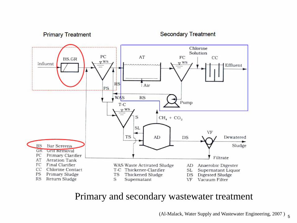
Primary and secondary wastewater treatment
(Al-Malack, Water Supply and Wastewater Engineering, 2007 )5

(Viessman et al., Water Supply and Pollution Control, 2009 )
Coarse bar racks
6
Mechanical cleaned medium screen
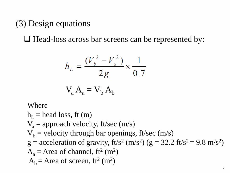
(3) Design equations
Head-loss across bar screens can be represented by:
Where
hL = head loss, ft (m)
Va = approach velocity, ft/sec (m/s)
Vb = velocity through bar openings, ft/sec (m/s)
g = acceleration of gravity, ft/s2 (m/s2) (g = 32.2 ft/s2 = 9.8 m/s2)
Aa = Area of channel, ft2 (m2)
Ab = Area of screen, ft2 (m2)
Va Aa = Vb Ab
7
Example 2-1: A mechanical bar screen is to be used in an
approach channel with a maximum velocity of 1 m/s. The
bars are 15 mm thick, and the openings are 25 mm wide.
Determine:
(1) The velocity between the bars
(2) The head loss in meters
(4) Shredding
Grinders/ barminutors/ comminutors installed before
screening during wastewater treatment in some cases
Cut solids to about ¼ to ¾ in. in size
8

Mixing can be classified as
2. Mixing and flocculation
(1) Why mixing and flocculation
Continuous-rapid mixing (less than 30s) or rapid
mixing
9
blending of chemicals with wastewater (e.g., the addition
of alum or iron salts prior to flocculation + dispersion of
chlorine into wastewater for disinfection)
blending of miscible liquids
addition of chemicals to sludge and biosolids to improve
their dewatering characteristics
microflocs are produced

10
Continuous mixing (i.e., ongoing)
used where contents of a reactor or holding tank or basin
must kept in suspension (e.g., in equalization basins,
flocculation basins, suspended growth biological treatment
processes, aerated lagoons, and aerobic digesters)
Flocculation one application of continuous
mixing
form aggregates or flocs from finely divided particles and
from chemically destabilized particles
follow rapid mixing where chemicals have been added to
destabilize the particles agglomerate microflocs to
larger ones that can be removed readily by settling or
filtration

Primary and secondary wastewater treatment
(Al-Malack, Water Supply and Wastewater Engineering, 2007 )11

Tertiary wastewater treatment processes
(Al-Malack, Water Supply and Wastewater Engineering, 2007 )12
13
Mixing devices
(2) System design for rapid mixing
Mechanical agitators most common
(e.g., using an impeller in a tank with stator
baffles) type of impellers
Pneumatic agitators through hydraulic
action (e.g., a jet injector mixer)
Static in-line blenders inserted into a
pipe for blending normally for gas-water
contact
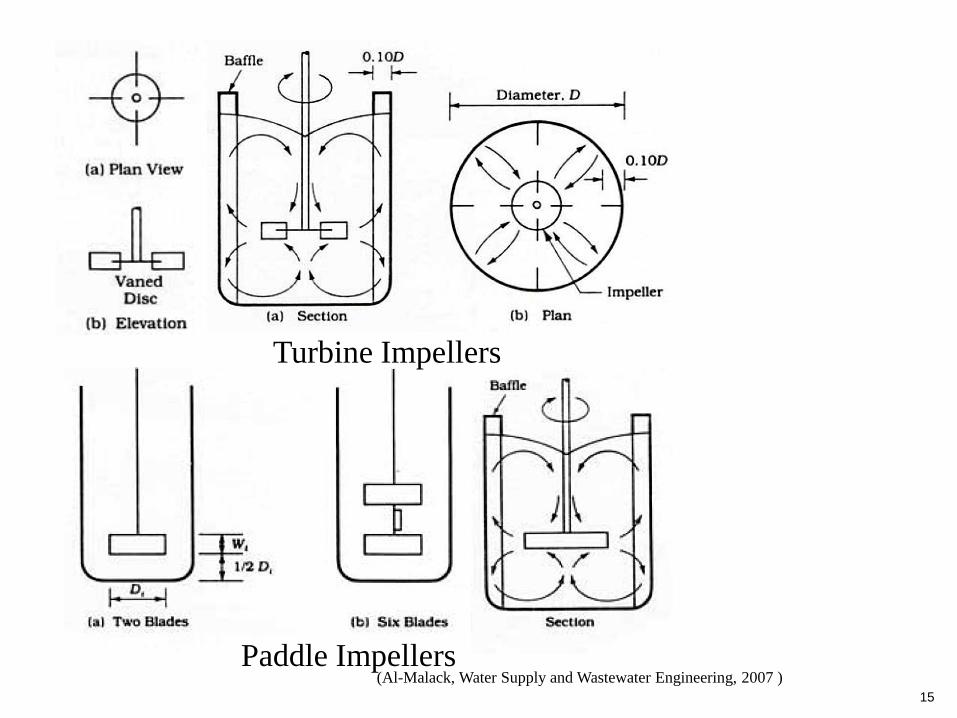
Turbine Impellers
Paddle Impellers
Propeller Impellers

(Viessman et al., Water Supply and Pollution Control, 2009 )
A vertical-shaft impeller-type mechanical rapid
mixer for dispersion of chemicals into water
14
15
Turbine Impellers
Paddle Impellers(Al-Malack, Water Supply and Wastewater Engineering, 2007 )
16
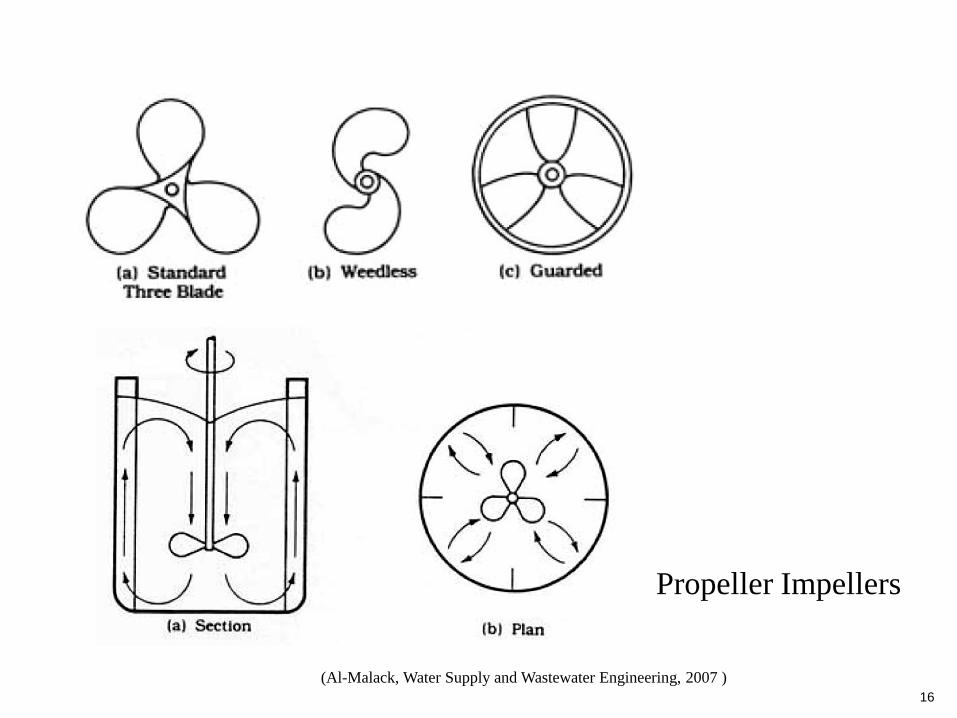
Propeller Impellers
(Al-Malack, Water Supply and Wastewater Engineering, 2007 )

17
(Viessman et al., Water Supply and Pollution Control, 2009 )
Jet injection mixer
Jet injection of chemical
into the water flow in a
pipe
Static mixing elements
that are inserted into a
pipe for in-line blending
of chemicals
18
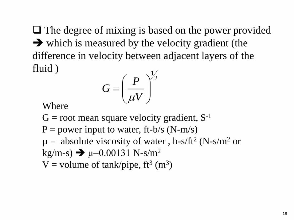
The degree of mixing is based on the power provided
which is measured by the velocity gradient (the
difference in velocity between adjacent layers of the
fluid )2
1
V
PG
Where
G = root mean square velocity gradient, S-1
P = power input to water, ft-b/s (N-m/s)
µ = absolute viscosity of water , b-s/ft2 (N-s/m2 or
kg/m-s) μ=0.00131 N-s/m2
V = volume of tank/pipe, ft3 (m3)

19
RtQV Where
V = volume of tank/pipe, ft3 (m3)
Q = discharge rate, cfs (m3/s)
tR = the mean residence time, s
The volume of the tank or pipe containing the
water can be computed by the equation
G (Sec-1 )tR (Sec )
Typical tR and G for rapid mixing basins
Example 2-2: Chemical addition in a 25-mgd
wastewater treatment plant will be performed in two
parallel mixing basins with mechanical mixers. The
mixing intensity as measured by the root mean velocity
gradient should be a minimum of 750 s-1, and the mean
residence time should be 15 s at the design flow. Find the
volume of the tanks and the power required for the mixers.
The water temperature varies between 15 and 20 ºC
annually. Assume the mechanical mixer is 70% efficient
in transferring power to the water.
20

21
(Viessman et al., Water Supply and Pollution Control, 2009 )

22
Mixing devices
(3) System design for flocculation
The common mechanical mixing devices paddle
(reel) flocculators and vertical-turbine mixers
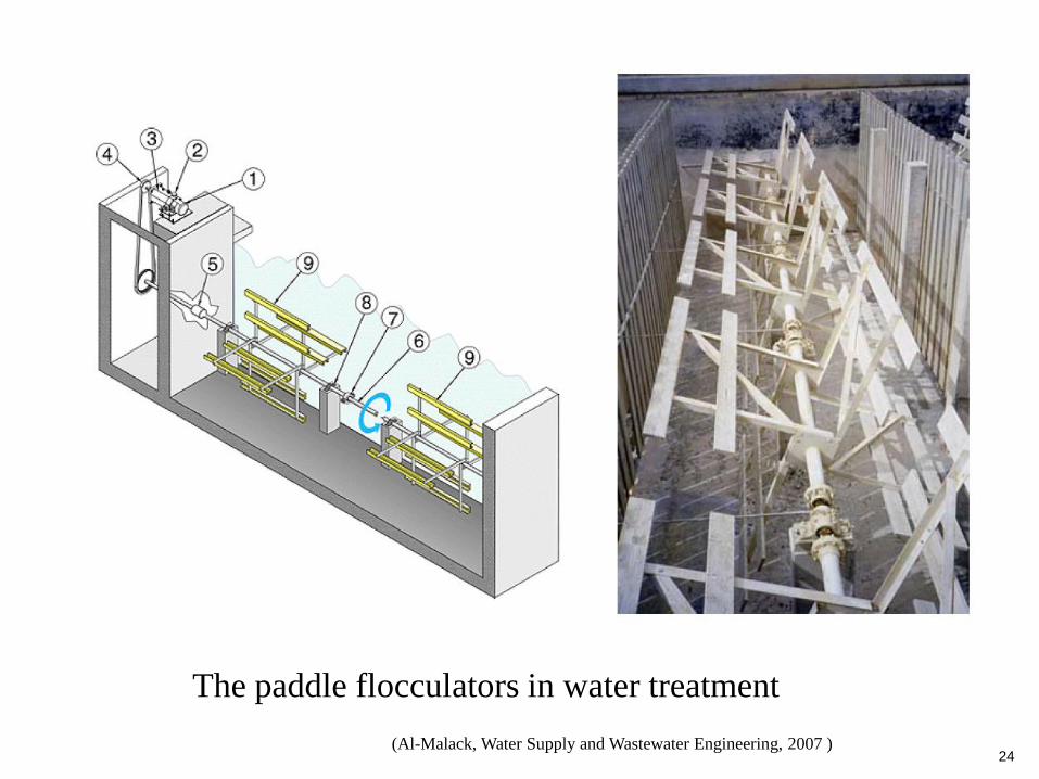
The paddle flocculator consists of a shaft with
protruding steel arms that support wooden, plastic or
steel blades the paddle shaft could be located
transverse (more common) or parallel to the flow The paddle units slowly rotate (1-10 rpm) collision
among the floc particles that are held in suspension by
the agitation growth of the suspended particles from
colloids to settable floc

23
(Viessman et al., Water Supply and Pollution Control, 2009 )
The paddle flocculator
The vertical-turbine mixer
24
The paddle flocculators in water treatment
(Al-Malack, Water Supply and Wastewater Engineering, 2007 )

25
The paddle flocculator with the paddle shaft located
transverse to the flow
The paddle flocculator with the paddle shaft located
parallel to the flow(Al-Malack, Water Supply and Wastewater Engineering, 2007 )

26
The power dissipated in water by a paddle flocculator
can be calculated as:
2
13
kACP
pd
Where
P = power dissipated, ft-b/s (N-m/s)
Cd = coefficient of drag
A = Paddle area, ft2 (m2)
ρ = density of the water, b-s2/ft4 (kg/m3)
vp = velocity of the paddle relative to water, ft/s (m/s)
K = ratio of the rotational velocity of water to the
velocity of the paddle, normally 0.25-0.50, with 0.3
being a common value
27
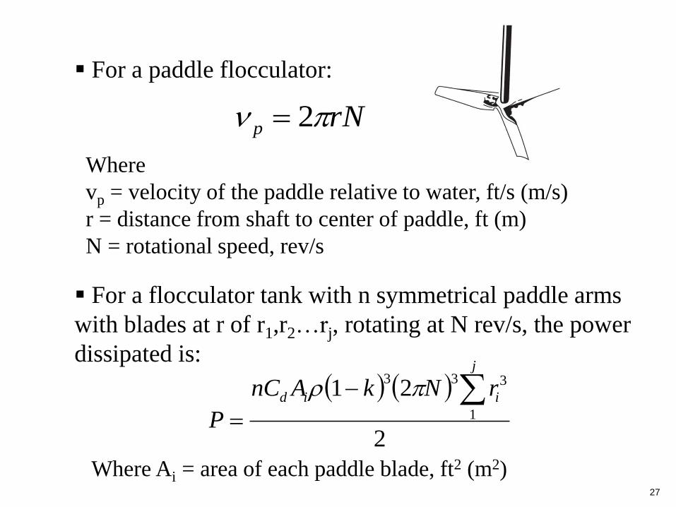
For a paddle flocculator:
rNp 2
Where
vp = velocity of the paddle relative to water, ft/s (m/s)
r = distance from shaft to center of paddle, ft (m)
N = rotational speed, rev/s
For a flocculator tank with n symmetrical paddle arms
with blades at r of r1,r2…rj, rotating at N rev/s, the power
dissipated is:
2
211
333
j
iid rNkAnC
P
Where Ai = area of each paddle blade, ft2 (m2)
Example 2-3: A 25-mgd wastewater treatment plant has
a flocculation tank 64 ft long and 100 ft wide with a water
depth of 16 ft. The four horizontal shafts of paddle
flocculator are in compartments separated by baffles. All
the paddle units have four arms with two blades, with
radii of 3.0 and 6.0 ft measured from the shaft to the
center of the 0.80-ft-wide boards. The total length of the
paddle boards across the tank is 90 ft. Assume a ratio of
water velocity to paddle velocity of 0.3, rotational speed
of 3 rev/min, Cd equal to 1.8, and water temperature of
50F. Calculate the velocity gradient.
28

To separate solids from liquid using the force of
gravity in sedimentation, only suspended solids
(SS) are removed
3. Sedimentation
(1) Why sedimentation
29
Particles pollutants with adverse impacts to
aquatic life (e.g., damage fish gills, smother coral
reefs)
Particle settling clogs river, fills up reservoirs
Particles may carry adsorbed chemicals (e.g.,
PCBs in Hudson river)
30
(2) Type of sedimentation (settling)
Type I settling (free settling)
Type II settling (settling of flocculated particles)
Type III settling (zone or hindered settling)
Type IV settling (compression settling)
In wastewater treatment plants sedimentation is
used to reduce SS in the influent wastewater and to
remove settleable solids after biological treatment

Primary and secondary wastewater treatment
(Al-Malack, Water Supply and Wastewater Engineering, 2007 )31

Tertiary wastewater treatment processes
(Al-Malack, Water Supply and Wastewater Engineering, 2007 )32

33
(3) Type I settling (free settling or discrete settling)
The gravitational force on particle (FI, kg-m/s2)
Where
ρp = particle density and ρw = water density (kg/m3)
VP = particle volume (m3) and d = particle diameter (m)
g = acceleration due to gravity (9.81 m/s2)
3
6dggVF wppwpI
It means settling of discrete (nonflocculent)
particles (e.g., settling of sand particles in grit
chamber)
In type I settling a particle will accelerate
until the drag force (FD) equals the impelling
gravitational (due to weight) force on particle (FI)
settling occurs at a constant velocity, Vs (m/s)
(2.1)
34
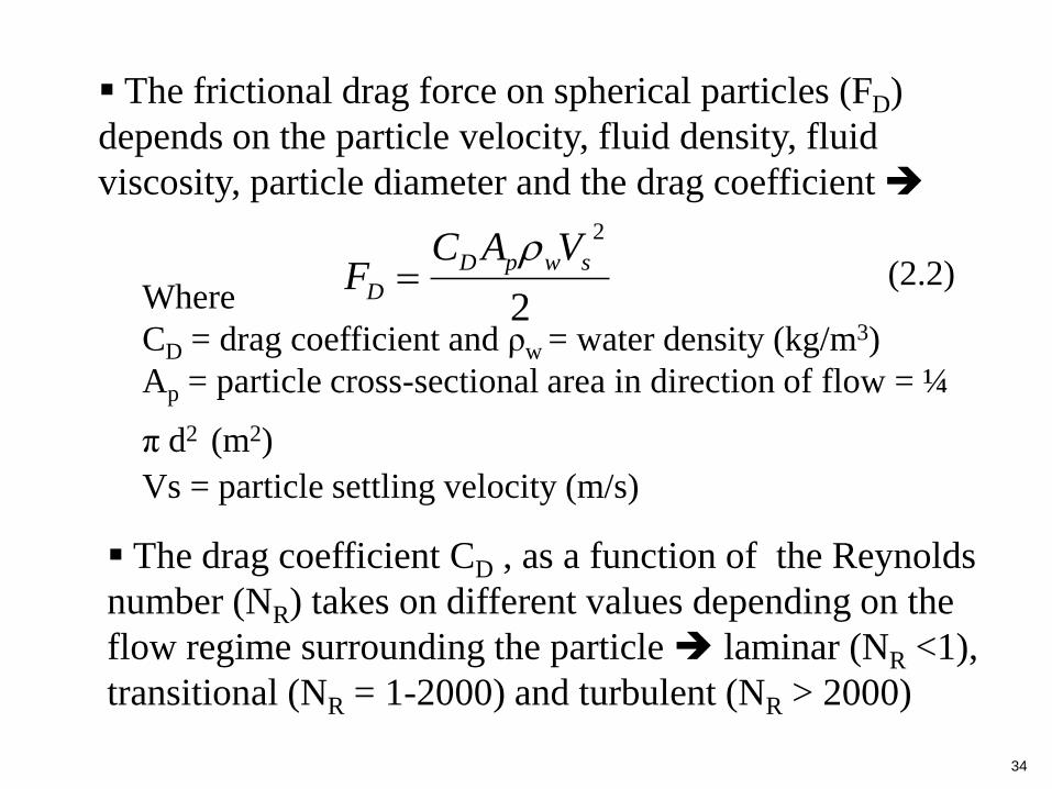
The frictional drag force on spherical particles (FD)
depends on the particle velocity, fluid density, fluid
viscosity, particle diameter and the drag coefficient
2
2
swpD
D
VACF
Where
CD = drag coefficient and ρw = water density (kg/m3)
Ap = particle cross-sectional area in direction of flow = ¼
π d2 (m2)
Vs = particle settling velocity (m/s)
The drag coefficient CD , as a function of the Reynolds
number (NR) takes on different values depending on the
flow regime surrounding the particle laminar (NR <1),
transitional (NR = 1-2000) and turbulent (NR > 2000)
(2.2)
35
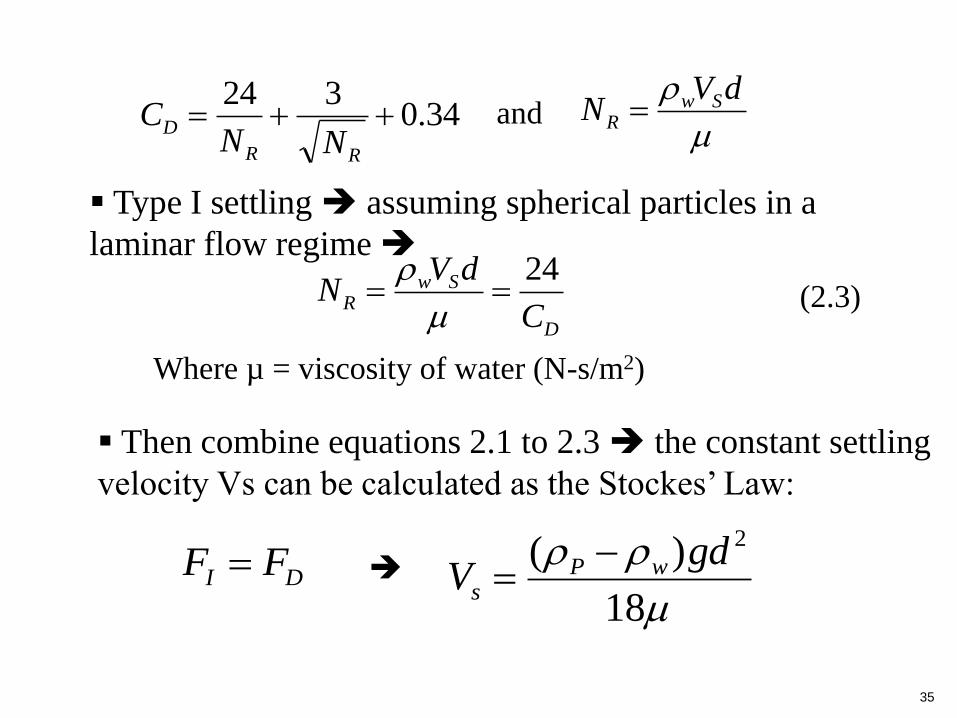
Where µ = viscosity of water (N-s/m2)
Type I settling assuming spherical particles in a
laminar flow regime
D
SwR
C
dVN
24
Then combine equations 2.1 to 2.3 the constant settling
velocity Vs can be calculated as the Stockes’ Law:
dVN Sw
R 34.0324
RR
DNN
C and
(2.3)
DI FF
18
)( 2gdV wP
s
36
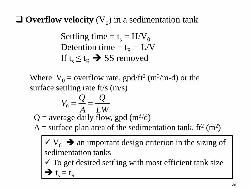
Overflow velocity (V0) in a sedimentation tank
Settling time = ts = H/V0
Detention time = tR = L/V
If ts ≤ tR SS removed
Q = average daily flow, gpd (m3/d)
A = surface plan area of the sedimentation tank, ft2 (m2)
LW
Q
A
QV 0
V0 an important design criterion in the sizing of
sedimentation tanks
To get desired settling with most efficient tank size
ts = tR
Where V0 = overflow rate, gpd/ft2 (m3/m-d) or the
surface settling rate ft/s (m/s)
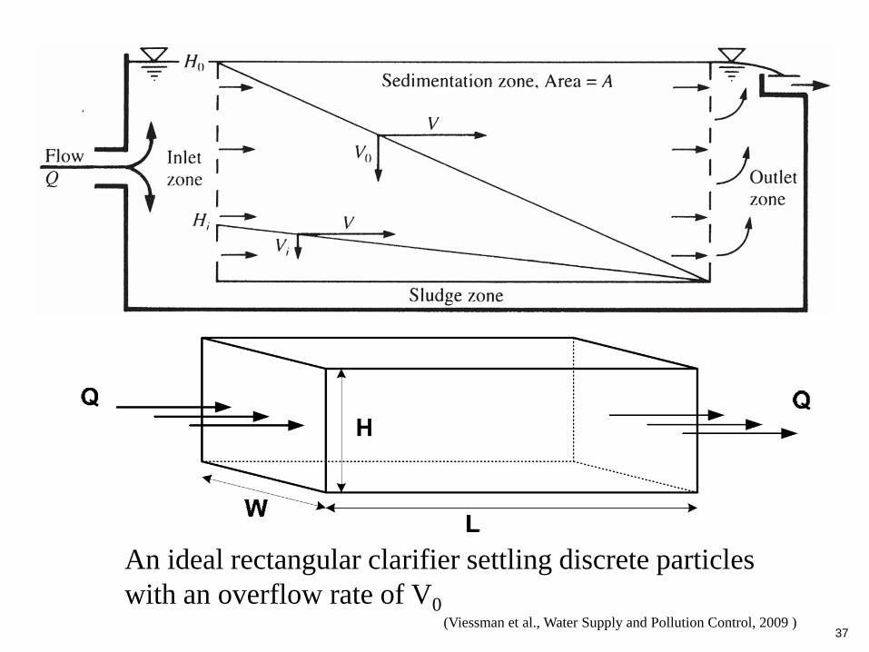
37(Viessman et al., Water Supply and Pollution Control, 2009 )
An ideal rectangular clarifier settling discrete particles
with an overflow rate of V0

38
Sedimentation efficiency under different H?
(Shanahan, Water and Wastewater Treatment Engineering, 2006 )
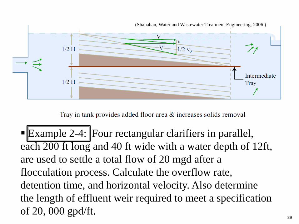
39
Example 2-4: Four rectangular clarifiers in parallel,
each 200 ft long and 40 ft wide with a water depth of 12ft,
are used to settle a total flow of 20 mgd after a
flocculation process. Calculate the overflow rate,
detention time, and horizontal velocity. Also determine
the length of effluent weir required to meet a specification
of 20, 000 gpd/ft.
(Shanahan, Water and Wastewater Treatment Engineering, 2006 )
40
(4) Type II settling (settling of flocculated particles)
Type I settling assume uniform settling velocity
it relatively rare in water, especially wastewater
treatment
In treatment, many particles are present as a
particle falls, it collides with other particles and
they stick together to form larger particles
Chemicals are also added to enhance
coagulation and flocculation chemicals are
added to (quickly) cause coagulation
(destabilization and initial coalescing of colloidal
particles), which then (slowly) flocculate
(formation of large particles, flocs, from smaller
particles)
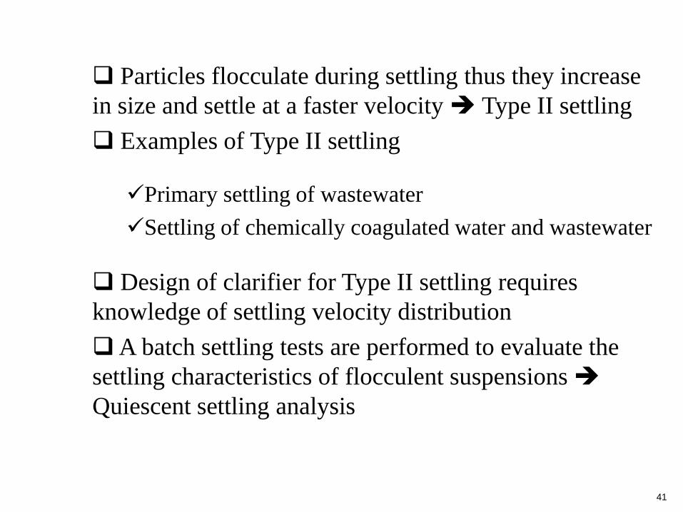
41
Particles flocculate during settling thus they increase
in size and settle at a faster velocity Type II settling
Examples of Type II settling
Design of clarifier for Type II settling requires
knowledge of settling velocity distribution
A batch settling tests are performed to evaluate the
settling characteristics of flocculent suspensions
Quiescent settling analysis
Primary settling of wastewater
Settling of chemically coagulated water and wastewater

42(Shanahan, Water and Wastewater Treatment Engineering, 2006 )
Apparatus for Quiescent settling analysis
Lab apparatus is a column
with diameter ≥ 5 inches to
reduce wall effects
Apparatus has a depth of 8
to 10 ft and sampling ports
every 2 ft.
Initially suspended
sediment is poured into
column, well mixed and
allowed to settle
Samples are taken at each
port (#1-#5) with selected
time intervals C/C0
determined
C/C0 vs time and depth is
plotted on a graph

43
(Tchobanoglous et al., Wastewater Engineering, 2003)
The percentage removal at certain time t2
2222
54
5
443
5
332
5
221
5
1 RR
h
hRR
h
hRR
h
hRR
h
h
44
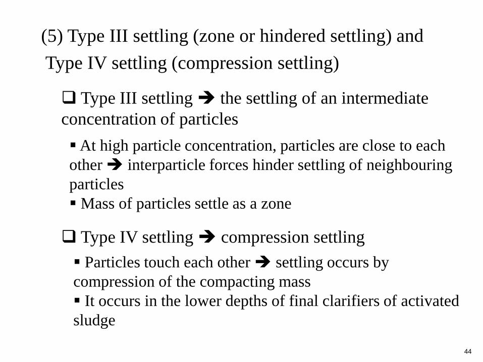
(5) Type III settling (zone or hindered settling) and
Type IV settling (compression settling)
Type III settling the settling of an intermediate
concentration of particles
At high particle concentration, particles are close to each
other interparticle forces hinder settling of neighbouring
particles
Mass of particles settle as a zone
Type IV settling compression settling
Particles touch each other settling occurs by
compression of the compacting mass
It occurs in the lower depths of final clarifiers of activated
sludge
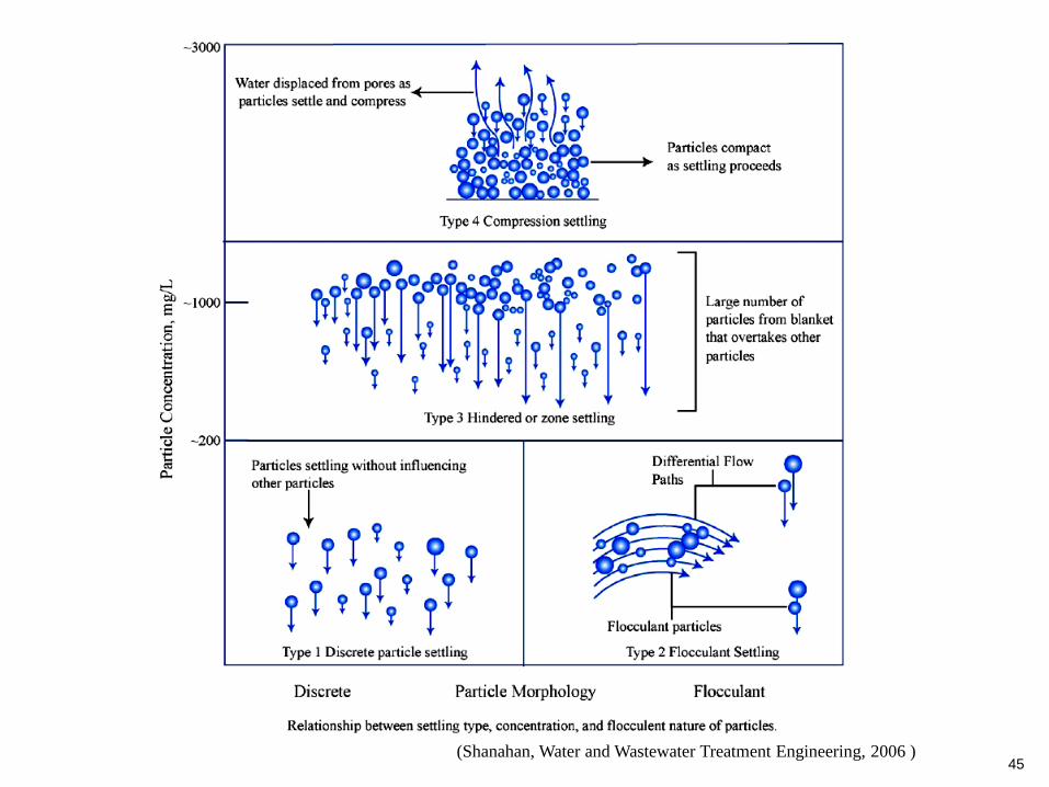
45(Shanahan, Water and Wastewater Treatment Engineering, 2006 )

46
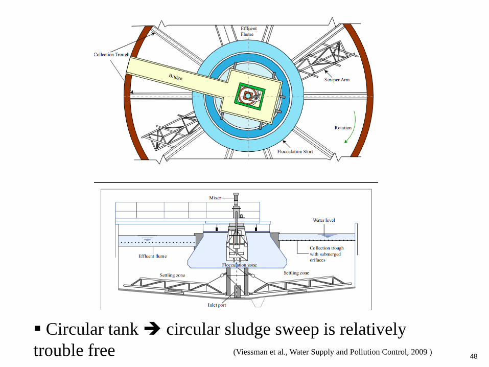
(6) Type of sedimentation tanks
Rectangular and circular settling tank
Rectangular tank usually have chain-drive scrapers
to bring sludge to withdrawal trough in tank bottom
typically 3m deep for water treatment
Circular tank inflow at center and outflow along
perimeter weir or radial collection troughs circular
rake arm to rake sludge to center (in water treatment) or
with suction pipes (in wastewater treatment)
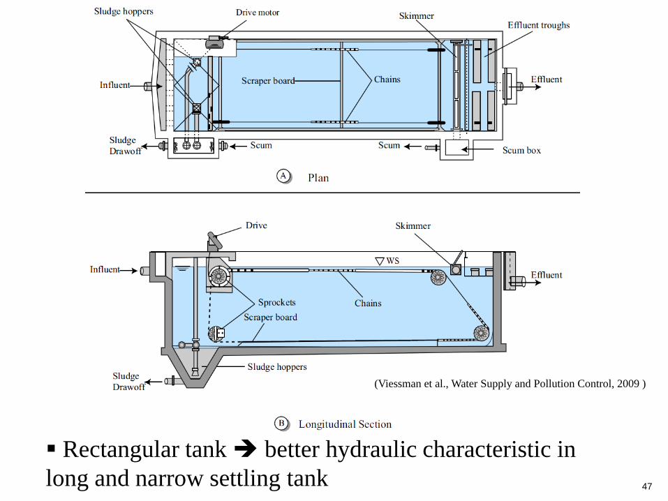
47
Rectangular tank better hydraulic characteristic in
long and narrow settling tank
(Viessman et al., Water Supply and Pollution Control, 2009 )
48(Viessman et al., Water Supply and Pollution Control, 2009 )
Circular tank circular sludge sweep is relatively
trouble free

49
(Viessman et al., Water Supply and Pollution Control, 2009 )
Sedimentation tanks for wastewater treatment
After the water has been settled, some fine
solids/flocs may still be in suspension removal of
these fine solids can be achieved by filtration
Filtration follows sedimentation to separate
nonsettleable solids from wastewater by passing
through a porous medium
Filtration help to produce high-quality
wastewater effluent
4. Filtration
(1) Why filtration
50
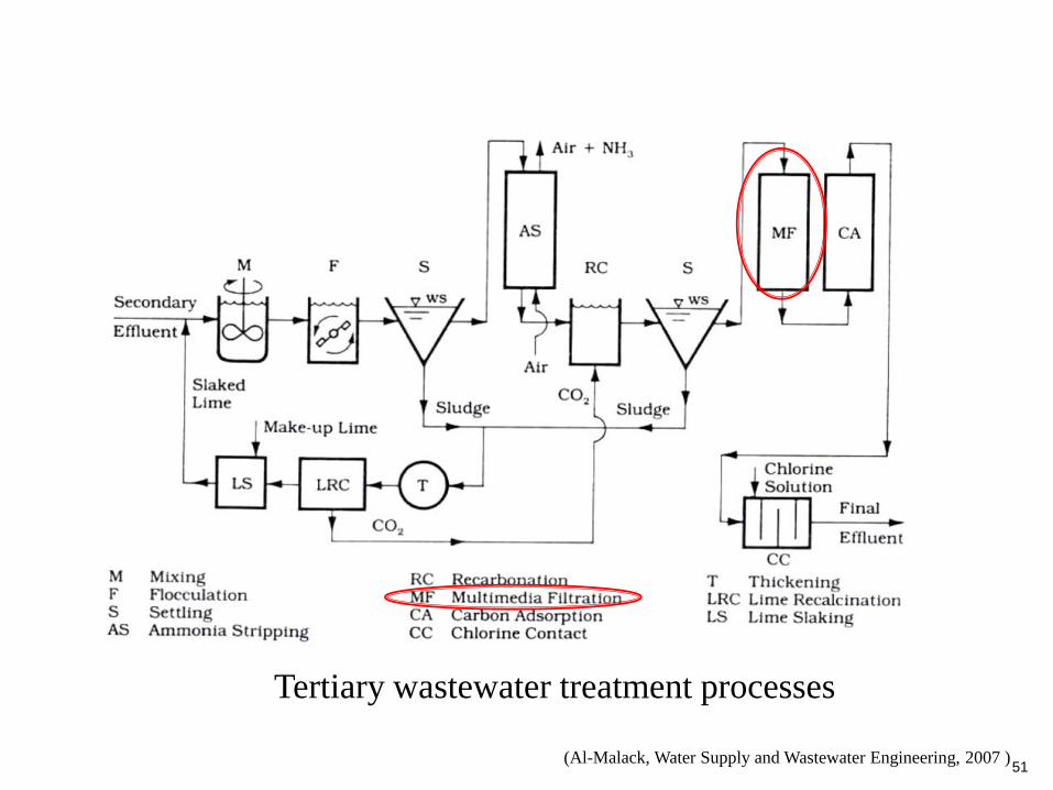
Tertiary wastewater treatment processes
(Al-Malack, Water Supply and Wastewater Engineering, 2007 )51

52
(2) Description of a typical granular filter system
(Shanahan, Water and Wastewater Treatment Engineering, 2006 )

53
During filtration, water level is 0.91 to 1.2 m above sand
water passes downward through the media water
passes into the underdrain system
Flow of filtered water flow is controlled by the rate of
flow controller (RFC) standard filtration rate is 1.36
l/s-m2 of filter bed
Influent and effluent valves are open + washwater and
waste washwater valves are closed
Particles larger than 1µm captured by sedimentation
and interception
Particles smaller than 1µm captured by diffusion
Most diffcult particles to capture about 1µm in size
Dual media provide better capture than single media

54(Viessman et al., Water Supply and Pollution Control, 2009 )
usually
sand
crushed
anthracite
garnet
Cross section of the media in a dual-media fiter
Filter media
55
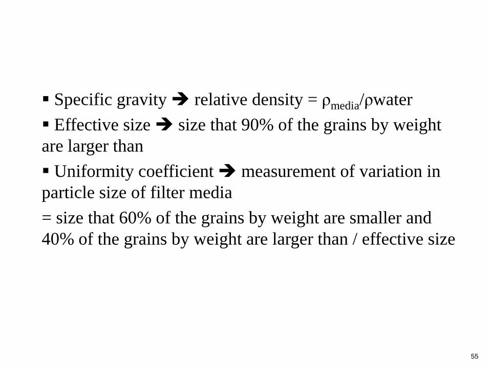
Specific gravity relative density = ρmedia/ρwater
Effective size size that 90% of the grains by weight
are larger than
Uniformity coefficient measurement of variation in
particle size of filter media
= size that 60% of the grains by weight are smaller and
40% of the grains by weight are larger than / effective size
56
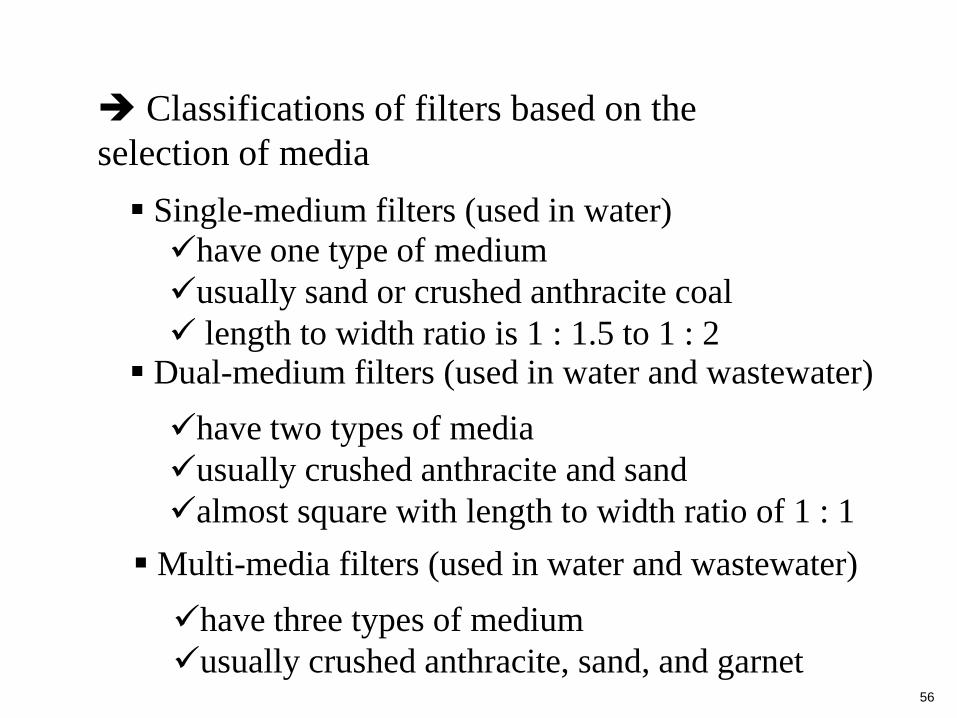
Classifications of filters based on the
selection of media
Single-medium filters (used in water)
have one type of medium
usually sand or crushed anthracite coal
length to width ratio is 1 : 1.5 to 1 : 2 Dual-medium filters (used in water and wastewater)
have two types of media
usually crushed anthracite and sand
almost square with length to width ratio of 1 : 1
Multi-media filters (used in water and wastewater)
have three types of medium
usually crushed anthracite, sand, and garnet
57
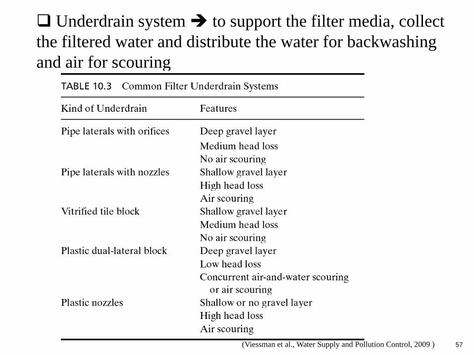
Underdrain system to support the filter media, collect
the filtered water and distribute the water for backwashing
and air for scouring
(Viessman et al., Water Supply and Pollution Control, 2009 )
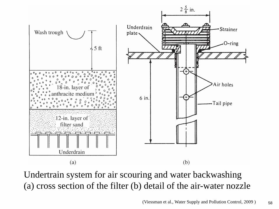
58(Viessman et al., Water Supply and Pollution Control, 2009 )
Undertrain system for air scouring and water backwashing
(a) cross section of the filter (b) detail of the air-water nozzle

59
(3) Head lost and backwash
Head loss caused by accumulation of
particles on top and within the depth of the
filter
Head loss through a clean granular-media
filter generally less than 3ft (0.9m)
With accumulation of impurities head
loss gradually increases until the filter is
backwashed usually at 8-10ft (2.4-3.0 m)
60
Objective of backwash to remove
accumulated particles on the surface and within
the filter medium
Backwash performed using wash water or
air scouring
During backwash, the sand bed expands bed
expansion is between 20 to 50%
Backwash flow between 10.2 to 13.6 l/s-m2
Backwash continues till the waste washwater is
relatively clear