chapter 1ct
TRANSCRIPT
8/8/2019 Chapter 1ct
http://slidepdf.com/reader/full/chapter-1ct 1/26
CHAPTER 1
BASICS OF CIRCUIT ANALYSIS
Classification of Circuit Element
1. Active element [energy sources]
They are voltage and current sources. E.g. Generator, Vaccum tubeTransistors etc.
2. Passive element
These elements either dissipate energy in the form of heat or store energy
E.g. R, L, C
R- Dissipate energy in the form of heat.
L- Stores energy in its magnetic field.
C- Stores energy in its electrostatic field.
Electrical Network
The connection of passive and active elements by mean of conductor iscalled an active network. Any arrangement of the various electrical sourcesalong with the different circuit elements is called and electrical network.
Lumped and Distributed Element s
Physically separate elements such as resistor, capacitor and inductor arecalled lumped elements.
A distributed element is one which is not separable for electrical purposes. A transmission line has distributed resistance, capacitance andinductance along with its length.
Bilateral and Unilateral Elements
In a bilateral element the voltage current relation is the same for currentflowing either direction.
A unilateral element has different relation between voltage and current
for the two possible direction of current.

8/8/2019 Chapter 1ct
http://slidepdf.com/reader/full/chapter-1ct 2/26
E.g. Bilateral Element: Resistor, Inductor, Capacitor
E.g. Unilateral Element: Vaccum tubes, Silicon diodes, Metal rectifier etc.
Linear and Non-Linear Elements
An element is said to be linear if it satisfies the linear voltage currentrelationship. It means that for linear elements the relation between V and I islinear.
For example the current passing through a resistor proportional to thevoltage applied. All elements which do not satisfy linear voltage currentrelationship are called non-linear element.
Element Voltage across elements Current through
elements
R v= iR i=
Lv= L i= ∫ vdt
Cv= ∫ idt
i= C
Series Combination of Resistance
= + +
=I =I =I
= = =
Total power P = VI = [ ] I
P = V =

8/8/2019 Chapter 1ct
http://slidepdf.com/reader/full/chapter-1ct 3/26
P = + +
P = =
for ac circuits
By kvl V = [Phasor Sum]
By ohm’s law V = I
=I =I =I
I = = I [ ]
=
Average power P = VI cos
Cos = Power factor =
Parallel Combination of Resistance
= or =
= =
V = I = I =
V = =
For ac circuit R is replaced by Z in the formula
Parallel Combination of Admittance
=
= V = V
8/8/2019 Chapter 1ct
http://slidepdf.com/reader/full/chapter-1ct 4/26
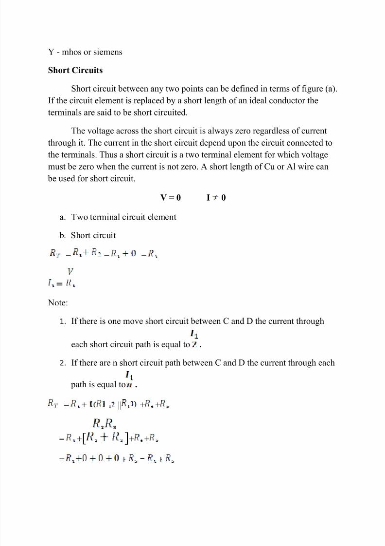
Y - mhos or siemens
Short Circuits
Short circuit between any two points can be defined in terms of figure (a).If the circuit element is replaced by a short length of an ideal conductor theterminals are said to be short circuited.
The voltage across the short circuit is always zero regardless of currentthrough it. The current in the short circuit depend upon the circuit connected tothe terminals. Thus a short circuit is a two terminal element for which voltagemust be zero when the current is not zero. A short length of Cu or Al wire can
be used for short circuit.
V = 0 I 0
a. Two terminal circuit element
b. Short circuit
= = =
=
Note:
1. If there is one move short circuit between C and D the current through
each short circuit path is equal to .
2. If there are n short circuit path between C and D the current through each
path is equal to .
= + || + +
= +[ ]+ +
=

8/8/2019 Chapter 1ct
http://slidepdf.com/reader/full/chapter-1ct 5/26
=
Note:
The resistance are not effective whatever may be their values.Itis because they are short circuit. The current through resistance which are shortcircuit will always be zero.
Open Circuits
The current in an open circuit is always zero regardless of the voltage
across it. V 0 I = 0
I =
Network
Any interconnections of passive and active element constitute an electricnetwork. A network contain passive elements is called passive network. Anetwork contain active elements is called active network.
Node
A node is a point in a network where two or more elements are joined.Junction of three of more elements is called is principle node. Junction of onlytwo elements is called a simple node.
Branch
The element or element in series connected between two principle nodesis called a branch.
Mesh (or Loop)
Mesh (or Loop) is a set of branches forming a closed path in a network issuch a way that if one branch is removed then remaining branches do not form aclosed path. A loop is a single closed path for current flow.
It has eight elements they are .

8/8/2019 Chapter 1ct
http://slidepdf.com/reader/full/chapter-1ct 6/26
It has seven loops: AOBA, AOCA, BOCB, BAOCB, BOACD, BOCAB, andABCA.
It has two simple nodes: a, b.
It has four principle nodes: O, A, B, C.
The network has six branches: AB, BC, CA, OA, OB, and OC.
No. of independent loop = b n+1
=6 4+1 = 3= no. of branch current
Kirchhoff’s Law
Voltage Law
In any network, the algebraic sum of the voltage drops across the circuitelements of any closed path (or loop or mesh) is equal to the algebraic sum of the electromotive forces in the path.
Around a closed path ∑ v = 0
Current Law
In any network, the algebraic sum of all the current meeting at a junction point is equal to the total current flowing away from that junction point. Thetotal current flowing towards a junction point is equal to the total currentflowing away from that junction point.
There are three method using these laws,
1. Branch current method: Apply both kcl & kvl.
2. Loop current method: Apply kvl only.
3. Node voltage method: Apply kcl only.
∑ I at junction point = 0
∑ I at junction point O = 0
+ = 0 i.e. + = +
Loop Current Method

8/8/2019 Chapter 1ct
http://slidepdf.com/reader/full/chapter-1ct 7/26
b=5 n=3 l=b n+1 = 5 3+1=3
Apply kvl in loop 1,
+( + ) =+ =
[ ] = --------------- 1
Apply kvl in loop 2,
=0
=0
------------------ 2
Apply kvl in loop 3,
+[ ] =
= --------------------- 3
Solving equation 1, 2 and 3Find the value of
1--» [ ] =
2--»
3--» =
Where
Self resistance of loop 1 =
Self resistance of loop 2 =
Self resistance of loop 3 =
=
+

8/8/2019 Chapter 1ct
http://slidepdf.com/reader/full/chapter-1ct 8/26
are mutual resistances,
In general
Note:
• If directions of loop current are not given assume all of them to beclockwise blindly. After solving if a particular loop current is found to benegative reverse only the direction of that loop current.
• The self resistances are always taken positive.
• The mutual resistance is negative if the current through it is the differenceof two loop current.
• The mutual resistance is positive if the current through it is the sum of two loop current.
•
• Loop current method can also be used for ac current circuits there youhave to replace R by Z.
•
If the network consists of practical current sources if it is convenient toconvert it into practical voltage source for loop current analysis.
Problem:
1. Write the mesh equation for the circuits shown in the figure find the eachloop current by also a) inspection method b) loop equation method.
By kvl

8/8/2019 Chapter 1ct
http://slidepdf.com/reader/full/chapter-1ct 9/26
For loop 1 7[ ] + 4[ ] =480 ---------------1
For loop 2 7[ ] + 4[ ] = -600 --------------2
For loop 3 12 --------3
Solving equation 1, 2, and 3
=5 = -55 = -10
By inspection method
∆ = 864
=
= - 8640 = -10A
=10A
Mesh Equation:
11
= - 600
= 0
Do it urself:
Write the mesh equation for the circuit shown in the figure and solve thecurrent in the 12Ω resistor.

8/8/2019 Chapter 1ct
http://slidepdf.com/reader/full/chapter-1ct 10/26
2. Write the mesh equation for the network shown in figure and find theloop current and power observed by 8Ω resistor and also to the loopcurrent.
By kvl
For loop 1 8 [ ] = 100
For loop 2 4[ ] + 10 = 0
For loop 3 = - 40
Solving equation 1, 2 and 3
=8.44A = 0.3067A = -2.638A
∆ = 2608
=
= 22000
= 8.44A
Mesh Equation:
12
24 = 0
= - 40

8/8/2019 Chapter 1ct
http://slidepdf.com/reader/full/chapter-1ct 11/26
3. Write the mesh equation by loop current method and find the loop current for the following network circuit and find the power absorbed by 3Ω resistor.
By kvl
For loop 1 2 [ ] = 13V
For loop 2 + 3 = 0
For loop 3 = 2A
Solving equation 1, 2 and 3
=2A = 1A = 3A
Power in 3Ω resistor =
= 23
= = 46 = = - 23
= 2A = 1A
Power = = =
Mesh Equation:
12
24 = 0
= - 40

8/8/2019 Chapter 1ct
http://slidepdf.com/reader/full/chapter-1ct 12/26
4. Write the mesh equation and find the loop current for the below network.
AC circuits:
1. Apply the mesh current method and determine current through theresistor of the network shown in figure.
Apply kvl in loop 1
2 = 10
3
=
Apply kvl in loop 2
= 0
= 0
Current through 2Ω resistor =
Current through 1Ω resistor =
Current through 3Ω resistor
By inspection method
∆ = 11 = 40 = 10
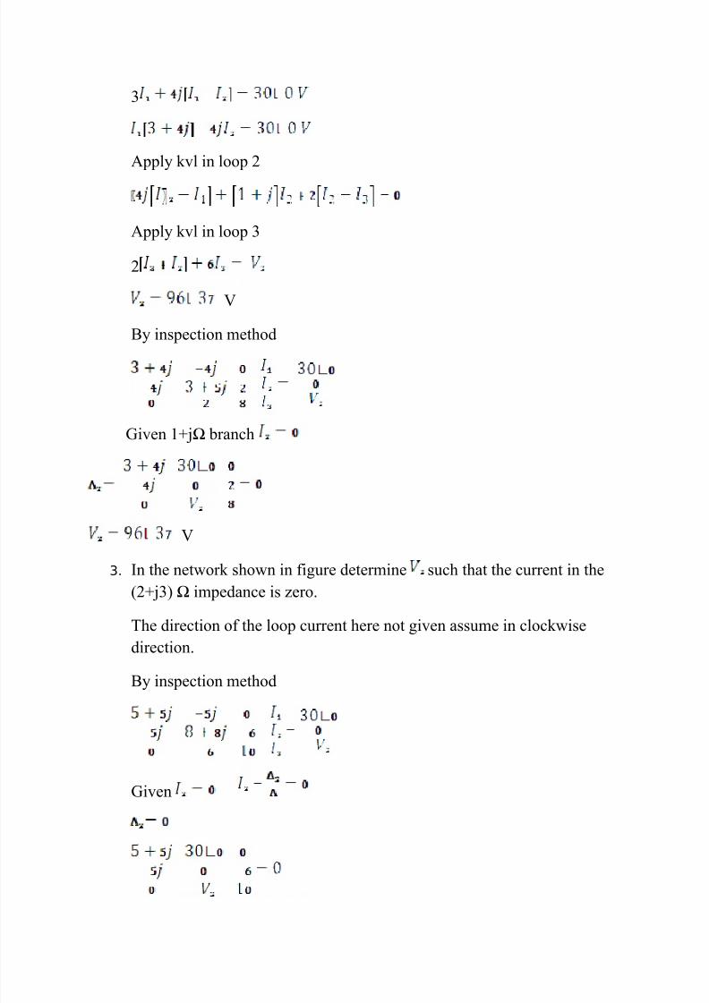
2. In the network shown in figure find the such that the current in the(1+j1) Ω branch is zero.
Apply kvl in loop 1
8/8/2019 Chapter 1ct
http://slidepdf.com/reader/full/chapter-1ct 13/26
3
Apply kvl in loop 2
Apply kvl in loop 3
2
V
By inspection method
Given 1+jΩ branch
V
3. In the network shown in figure determine such that the current in the(2+j3) Ω impedance is zero.
The direction of the loop current here not given assume in clockwisedirection.
By inspection method
Given
8/8/2019 Chapter 1ct
http://slidepdf.com/reader/full/chapter-1ct 14/26
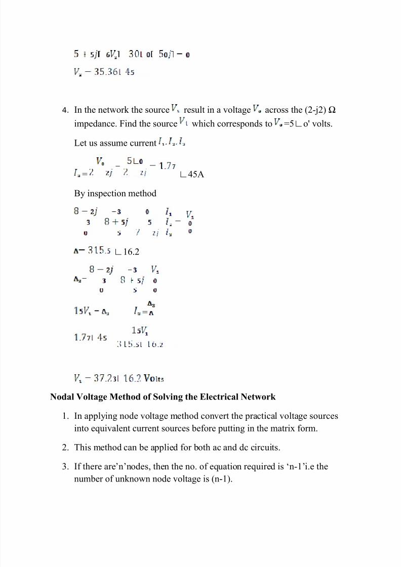
4. In the network the source result in a voltage across the (2-j2) Ω
impedance. Find the source which corresponds to =5∟o' volts.
Let us assume current
= ∟45A
By inspection method
∟16.2
=
Nodal Voltage Method of Solving the Electrical Network
1. In applying node voltage method convert the practical voltage sourcesinto equivalent current sources before putting in the matrix form.
2. This method can be applied for both ac and dc circuits.
3. If there are’n’nodes, then the no. of equation required is ‘n-1’i.e thenumber of unknown node voltage is (n-1).

8/8/2019 Chapter 1ct
http://slidepdf.com/reader/full/chapter-1ct 15/26
4. It is to be note whether given passive element is resistance (ohm) or conductor (mho or siemens) for dc admittance for ac.
5. Apply only kcl (note not used in kvl)
6. Assign voltage at each node.
7.
At node 1 apply kcl we get
At node 2 apply kcl we get
Solving 1 and 2 we get the value of
By inspection method
Problems
1. Frame the nodal equation of the network of figure below and hence find thedifference of potential between nodes 2 and 4.

8/8/2019 Chapter 1ct
http://slidepdf.com/reader/full/chapter-1ct 16/26
Let , be the node voltage at node 1, 2, 3 and node 4 is referencenode the voltage is zero .
By inspection method
To find
Apply kcl in node 1
Apply kcl in node 2
Apply kcl in node 3
But
2. Compare the nodal voltage of the given circuits
By inspection method
8/8/2019 Chapter 1ct
http://slidepdf.com/reader/full/chapter-1ct 17/26
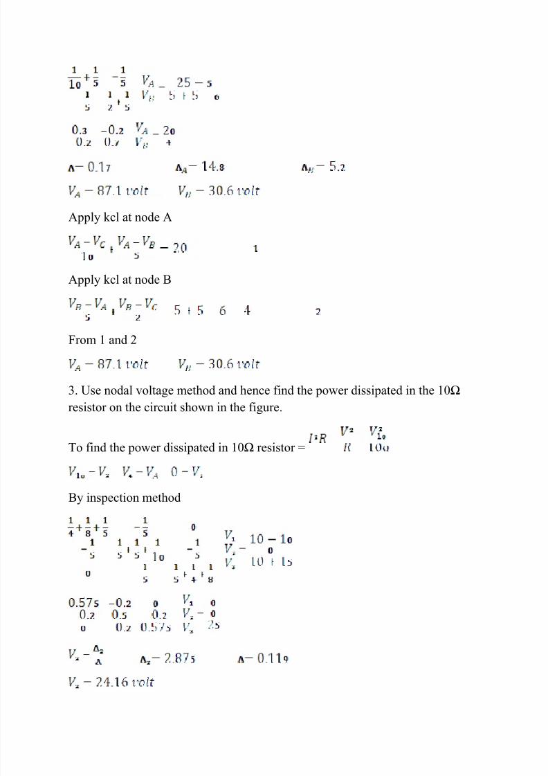
Apply kcl at node A
Apply kcl at node B
From 1 and 2
3. Use nodal voltage method and hence find the power dissipated in the 10Ω
resistor on the circuit shown in the figure.
To find the power dissipated in 10Ω resistor =
By inspection method

8/8/2019 Chapter 1ct
http://slidepdf.com/reader/full/chapter-1ct 18/26
Power =
4. Find the current , and the voltage , in the network using nodalanalysis.
By inspection method
8.33
8.33
Also
Substituting equation 1 in 2 we get
From original figure
=
=
=
5. Find the current through the galvanometer in the circuit shown by nodalmethod.
Note: on nodal method the ideal voltage source is connected between twonodes.

8/8/2019 Chapter 1ct
http://slidepdf.com/reader/full/chapter-1ct 19/26
In this problem the ideal voltage source is connected between two nodes. Takeone of these nodes as references preferably the node to which negative polarityof source is connected is taken as reference node (say node 4). Then the voltageof the other node (i.e. node 1)
To find current through Galvanometer
At node 2 apply kcl
At node 3 apply kcl
Solving 1 and 2
=
Note:
1. In the problem we cannot write matrix form by inspection.
2. The answer obtained by solving either by branch current or meshcurrent method will be same.
3. The same method is applicable for A.C circuit with ideal voltagesource.
6. Draw a possible network having the following nodal equation and determinethe nodal voltage.

8/8/2019 Chapter 1ct
http://slidepdf.com/reader/full/chapter-1ct 20/26
The nodal equation is matrix form
]
Network
The entire passive elements are admittance measured in mho.
AC Circuit by Nodal Analysis
1. Using nodal analysis find the node voltage and the voltage across and currentthrough 4Ω resistor in the circuit below.
By inspection method
∆=0.513 or 0.475 j0.195

8/8/2019 Chapter 1ct
http://slidepdf.com/reader/full/chapter-1ct 21/26
Current through 4Ω resistor,
Voltage across 4Ω resistor,
2. In the network shown in the figure find the node voltage Find also thecurrent supplied by the source.
By inspection method
∆=0.278 or 0.276 j0.033
Source Current,
3. Given the nodes 1 and 2 in network find the ratio of node voltage .
By inspection method
0.2
0.2
8/8/2019 Chapter 1ct
http://slidepdf.com/reader/full/chapter-1ct 22/26
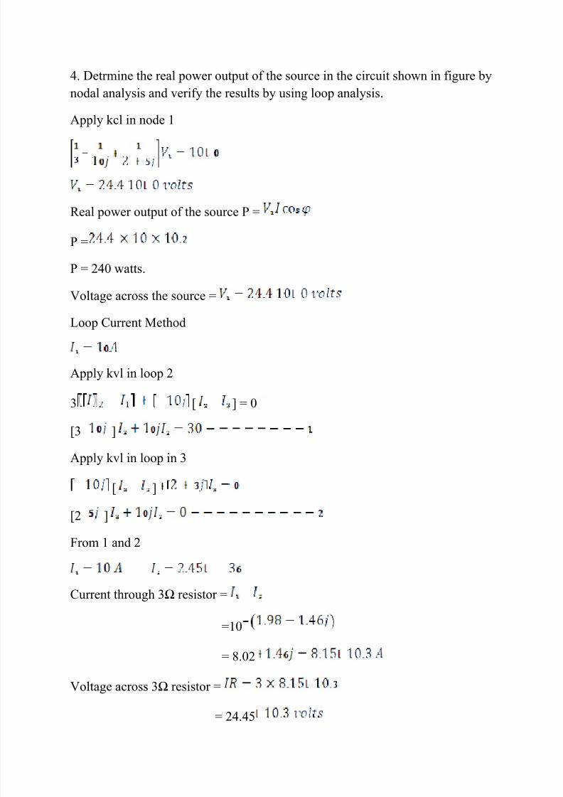
4. Detrmine the real power output of the source in the circuit shown in figure bynodal analysis and verify the results by using loop analysis.
Apply kcl in node 1
Real power output of the source P =
P =
P = 240 watts.
Voltage across the source =
Loop Current Method
Apply kvl in loop 2
3 [ ] = 0
[3 ]
Apply kvl in loop in 3
[ ]
[2 ]
From 1 and 2
Current through 3Ω resistor =
=10
= 8.02
Voltage across 3Ω resistor =
= 24.45

8/8/2019 Chapter 1ct
http://slidepdf.com/reader/full/chapter-1ct 23/26

8/8/2019 Chapter 1ct
http://slidepdf.com/reader/full/chapter-1ct 24/26
17. Find the current in 10Ω resistor in the network.
18. Find the current in 10Ω resistor in the network.
19. Find the current through the 2.5Ω resistor in the network by meshmethod. Also find the power supplied by the batteries.
20. Find the current through 10Ω ammeter connected between A & B of thenetwork by mesh method.
21. Find the current I in the network by mesh method.
22. Find the current flowing in all loops in the given network.
23.
In the circuit shown in figure . Find the value of resistor 24. Write loop equation for the following network and find the current
supplied by 8v source.
25. Find the current supplied by the voltage source and the voltage across thecurrent source in the network.
26.Find the voltage across the 10Ω resistor in the network by loop method.
Dependent Source
Current Controlled Voltage Source
1. Determine the current through 4Ωresistor of the network.
=
Energy Sources
8/8/2019 Chapter 1ct
http://slidepdf.com/reader/full/chapter-1ct 25/26
There are basically two types of energy sources, voltage source andcurrent source. These are classified as i) Ideal source and ii) Practical source.
Voltage Source
Ideal voltage source is defined as the energy source which gives constantvoltage across its terminals irrespective of the current drawn through itsterminals. The symbol for ideal voltage source is shown in the fig. at any timethe value of voltage at load terminals remain same. This is indicated by V-Icharacteristics shown in the fig.
But practically, every voltage source has small internal resistance shownin series with voltage source and is represented by as shown in the fig.
Because of the , voltage across terminals decreases slightly with increase incurrent and it is given by expression,
For ideal voltage source
i. Time invariant sources:
The sources in which voltage is not varying with time are known as
time invariant voltage sources or D.C. sources.
ii. Time variant sources:
The sources in which voltage is varying with time are known astime variant voltage sources or A.C. sources.
Current Sources
Ideal sources are the sources which gives constant current at its terminals
irrespective of the voltage appearing across its terminals. The symbol for idealcurrent sources is shown in fig. This is connected to the load as shown in the
fig. At any time, the value of the current flowing through load is same i.e. isirrespective of voltage appearing across its terminals. This is explained by V-Icharacteristics shown in the fig.
But practically, every current source has high internal resistance, shownin parallel with current sources and it is represented by . This is shown in
the fig.

8/8/2019 Chapter 1ct
http://slidepdf.com/reader/full/chapter-1ct 26/26
For ideal current source,
i) Time invariant sources:
The sources in which current is not varying with time are known astime invariant current sources or D.C. sources.
ii) Time variant sources:
The sources in which current is varying with time are known astime variant current sources or A.C. sources.
The sources which are discussed above are independent sources because thesesources do not depend on other voltages or currents in the network for their
value. These are represented by a circle with a polarity of voltage or direction of current indicated inside.
Dependent Sources
Dependent sources are those whose value of source depends on voltage or current in the circuit. Such sources are indicated by diamond as shown in thefig. and further classified as,
i) Voltage Dependent Voltage Source: It produces a voltage as a function of voltages elsewhere in the given circuit. This is called VDVS. It is shown in thefig.
ii) Current Dependent Current Source: It produces a current as a function of currents elsewhere in the given circuit. This is called CDCS. It is shown in thefig.
iii) Current Dependent Voltage Source: It produces a voltage as a function of
current elsewhere in the given circuit. This is called CDVS. It is shown in thefig.
iv) Voltage Dependent current Source: It produces a current as a function of voltage elsewhere in the given circuit. This is called VDCS. It is shown in thefig.