chapter 18 vlans - arista networks · pdf filechapter 18: vlans vlan conceptual overview 903...
TRANSCRIPT
901
Chapter 18
VLANsThis chapter describes Arista’s VLAN implementation and MAC address tables.
Sections in this chapter include:
• Section 18.1: VLAN Introduction
• Section 18.2: VLAN Conceptual Overview
• Section 18.3: VLAN Configuration Procedures
• Section 18.4: VLAN Configuration Commands
18.1 VLAN IntroductionArista switches support industry standard 802.1q VLANs. Arista EOS provides tools to manage andextend VLANs throughout the data center network.
18.2 VLAN Conceptual Overview
18.2.1 VLAN Definition
A virtual local area network (VLAN) allows a group of devices to communicate as if they were in thesame network regardless of their physical location. VLANs are layer 2 structures based on the 802.1Qstandard.
These parameters are associated with a VLAN:
• VLAN number (1-4094): VLAN numbers uniquely identify the VLAN within a network. VLAN 1exists by default; all other VLANs only exist after they are configured.
• VLAN name (optional): The VLAN name is a text string that describes the VLAN.
• VLAN state (active or suspended): The state specifies the VLAN transmission status within theswitch. In the suspended state, VLAN traffic is blocked on all switch ports. The default state isactive.
VLANs define layer 2 broadcast domains in a layer 2 network, in which each device can receivebroadcast frames sent by any other within the domain. Switches accommodating multiple broadcastdomains serve as multi-port bridges where each broadcast domain is a distinct virtual bridge. Trafficdoes not pass directly between different VLANs within a switch or between two switches.
18.2.2 VLAN Switching
Ethernet and port channel interfaces are configured as switched ports by default. Switched ports areconfigurable as members of one or more VLANs. Switched ports ignore all IP-level configurationcommands, including IP address assignments.

902
VLAN Conceptual Overview Chapter 18: VLANs
18.2.2.1 VLAN Trunking and Trunk Groups
Trunking extends multiple VLANs beyond the switch through a common interface or port channel.
A trunk group is the set of physical interfaces that comprise the trunk and the collection of VLANswhose traffic is carried on the trunk. The traffic of a VLAN that belongs to one or more trunk groups iscarried only on ports that are members of trunk groups to which the VLAN belongs, i.e., VLANsconfigured in a trunk group are ‘pruned’ off all ports that are not associated with the trunk group. Seethe Trunk Ports example section for further details.
Important! Be cautious when using allowed VLAN lists or trunk groups to ensure that the VLAN topology isconsistent with any Layer-2 control protocol topology, or unpredictable results can occur.
VLAN traffic is carried through Ethernet or LAG ports. A port’s switchport mode defines the number ofVLANs for which the port can carry traffic.
• Access ports carry traffic for one VLAN – the access VLAN. Access ports associate untaggedframes with the access VLAN. Access ports drop tagged frames that are not tagged with theaccess VLAN.
• Trunk ports carry traffic for multiple VLANs. Tag frames specify the VLAN for which trunk portsprocess packets.
18.2.2.2 Q-in-Q Trunking
A Q-in-Q network is a multi-tier layer 2 VLAN network. A typical Q-in-Q network is composed of aservice provider network (tier 1) where each node connects to a customer network (tier 2).
802.1ad is a networking standard that supports Q-in-Q networks by allowing multiple 802.1Q tags inan Ethernet frame.
Each interface in a customer network is assigned to a customer-VLAN (c-VLAN). Packets in c-VLANscontain 802.1q tags that switch traffic within the network. c-VLANs access the service provider VLAN(s-VLAN) through a provider switch. Customer switch ports connect to an s-VLAN through providerswitch edge ports, which are configured as dot1q ports and operate as follows:
• Inbound traffic (from customer switches): adds an s-VLAN tag, then forwards packets to theprovider network.
• Outbound traffic (to customer switches): removes the s-VLAN tag, then forwards packets to thecustomer network.
18.2.2.3 TPID (Configurable Ethertypes)
By default, VLAN-tagged packets carry a tag protocol identifier (TPID) of 0x8100. On some Aristaplatforms, however, the TPID of a switchport can be modified in accordance with IEEE 802.1ad to allowfor the use of 802.1q TPIDs other than 0x8100. Well known and standard tags include:
• 0x8100 customer VLAN
• 0x88a8 service VLAN tag used in provider bridging
• 0x9100 service VLAN tag used in provider bridging (common, but not standardized)
Other non-standard TPID values may also be configured for interoperability with legacy equipment ornon-standard systems. Values range from 0x600 (1536) through 0xFFFF (65535).
Non-default TPID values are most commonly used for provider bridging on a network-to-networkinterface.

Chapter 18: VLANs VLAN Conceptual Overview
903
18.2.3 VLAN Routing
Each VLAN can be associated with a switch virtual interface (SVI), also called a VLAN interface. TheVLAN interface functions in a routed network (layer 3) with an assigned IP subnet address. Connectingdifferent VLANs requires layer 3 networking.
18.2.3.1 VLAN Interfaces
A switched virtual interface (SVI) connects to the VLAN segment on the switch to provide layer 3processing for packets from the VLAN. An SVI can be activated only after it is connected to a VLAN.SVIs are typically configured for a VLAN to a default gateway for a subnet to facilitate traffic routing withother subnets.
In a layer 3 network, each VLAN SVI is associated with an IP subnet, with all stations in the subnetmembers of the VLAN. Traffic between different VLANs is routed when IP routing is enabled.
18.2.3.2 Internal VLANs
A routed port is an Ethernet or port channel interface that functions as a layer 3 interface. Routed portsdo not bridge frames nor switch VLAN traffic. Routed ports have IP addresses assigned to them andpackets are routed directly to and from the port.
The switch allocates an internal VLAN for an interface when it is configured as a routed port. Theinternal VLAN is assigned a previously unused VLAN ID. The switch prohibits the subsequentconfiguration of VLANs and VLAN interfaces with IDs corresponding to allocated internal VLANs.
18.2.3.3 VLAN Translation
VLAN translation allows you to map packets from one VLAN to another.

904
VLAN Configuration Procedures Chapter 18: VLANs
18.3 VLAN Configuration ProceduresThese sections describe basic VLAN configuration tasks.
• Section 18.3.1: Creating and Configuring VLANs
• Section 18.3.2: Configuring VLAN Switching
• Section 18.3.3: Creating and Configuring VLAN Interfaces
• Section 18.3.4: Allocating Internal VLANs
• Section 18.3.5: VLAN Translation
18.3.1 Creating and Configuring VLANs
The CLI provides two methods of creating VLANs.
• Explicitly through the vlan command.
• Implicitly through the switchport access vlan command.
The switchport access vlan command generates a warning message when it creates a VLAN.
To create a VLAN, use the vlan command in global configuration mode. Valid VLAN numbers rangebetween 1 and 4094. To create multiple VLANs, specify a range of VLAN numbers.
To edit an existing VLAN, enter the vlan command with the number of the existing VLAN.
Example
• This command creates VLAN 45 and enters VLAN configuration mode for the new VLAN.
switch(config)#vlan 45switch(config-vlan-45)#
Use the name (VLAN configuration mode) command to assign a name to a VLAN.
Example
• These commands assign the name Marketing to VLAN 45.
switch(config)#vlan 45switch(config-vlan-45)#name Marketingswitch(config-vlan-45)#show vlan 45VLAN Name Status Ports---- -------------------------------- --------- ------------------------45 Marketing active Et1
switch(config-vlan-45)#
To change a VLAN’s state, use the state command in VLAN configuration mode.
Examples
• These commands suspend VLAN 45. VLAN traffic is blocked on all switch ports.
switch(config)#vlan 45switch(config-vlan-45)#state suspendswitch(config-vlan-45)#show vlan 45VLAN Name Status Ports---- -------------------------------- --------- ------------------------45 Marketing suspended
switch(config-vlan-45)#

Chapter 18: VLANs VLAN Configuration Procedures
905
• These commands activate VLAN 45.
switch(config)#vlan 45switch(config-vlan-45)#state activeswitch(config-vlan-45)#show vlan 45VLAN Name Status Ports---- -------------------------------- --------- ------------------------45 Marketing active Et1
switch(config-vlan-45)#
18.3.2 Configuring VLAN Switching
The following describe the configuration of VLAN ports.
18.3.2.1 Access Ports
Access ports carry traffic for one VLAN, as designated by a switchport access vlan command.Access ports associate untagged frames with the access VLAN. Tagged frames received by theinterface are dropped unless they are tagged with the access VLAN.
To configure an interface group as an access port, use the switchport mode command.
Example
• These commands configure Ethernet interface 1 as an access port.
switch(config)#interface ethernet 1switch(config-if-Et1)#switchport mode accessswitch(config-if-Et1)#
To specify the port’s access VLAN, use the switchport access vlan command.
Examples
• These commands configure VLAN 15 as the access VLAN for Ethernet interface 5.
switch(config)#interface ethernet 5switch(config-if-Et5)#switchport access vlan 15switch(config-if-Et5)#
• These commands configure Ethernet interface 1 through 3 as access ports that process untaggedframes as VLAN 5 traffic.
switch(config)#interface Ethernet 1-3switch(config-if-Et1-3)#switchport mode accessswitch(config-if-Et1-3)#switchport access vlan 5switch(config-if-Et1-3)#show interfaces ethernet 1-3 vlansPort Untagged TaggedEt1 None 23,25Et2 18 -Et3 None 14switch(config-if-Et1-3)#
18.3.2.2 Trunk Ports
Trunk ports carry traffic for multiple VLANs. Messages use tagged frames to specify the VLAN for whichtrunk ports process traffic.
• The vlan trunk list specifies the VLANs for which the port handles tagged frames. The port dropsany packets tagged for VLANs not in the VLAN list.
• The native vlan is the VLAN where the port switches untagged frames.

906
VLAN Configuration Procedures Chapter 18: VLANs
To configure an interface group as a trunk port, use the switchport mode command.
Example
• These commands configure Ethernet interface 8 as a trunk port.
switch(config)#interface ethernet 8switch(config-if-Et8)#switchport mode trunkswitch(config-if-Et8)#
By default all VLANs are permitted on a port configured with ‘switchport mode trunk’. To limit the port’sVLAN trunk list, use the switchport trunk allowed vlan command. Only VLANs in the allowed list willbe permitted.
Examples
• These commands configure VLAN 15, 20, 21, 22, 40, and 75 as the explicitly permitted VLAN trunklist for Ethernet interface 12-16.
switch(config)#interface ethernet 12-16switch(config-if-Et12-16)#switchport trunk allowed vlan 15,20-22,40,75switch(config-if-Et12-16)#
• These commands explicitly permit VLAN 100 through 120 to the VLAN trunk list for Ethernetinterface 14.
switch(config)#interface ethernet 14switch(config-if-Et14)#switchport trunk allowed vlan add 100-120switch(config-if-Et14)#
To specify the port’s native VLAN, use the switchport trunk native vlan command.
Example
• These commands configure VLAN 12 as the native VLAN trunk for Ethernet interface 10.
switch(config)#interface ethernet 10switch(config-if-Et10)#switchport trunk native vlan 12switch(config-if-Et10)#
By default, ports send native VLAN traffic with untagged frames. The switchport trunk native vlancommand can also configure the port to send native VLAN traffic with tag frames.
Examples
• These commands configure Ethernet interface 10 to send native VLAN traffic as tagged.
switch(config)#interface ethernet 10switch(config-if-Et10)#switchport trunk native vlan tagswitch(config-if-Et10)#
• These commands configure Ethernet interface 12 as a trunk with VLAN 15 as the native VLAN.The port’s trunk list includes all VLANs except 201-300.
switch(config)#interface ethernet 12switch(config-if-Et12)#switchport mode trunkswitch(config-if-Et12)#switchport trunk native vlan 15switch(config-if-Et12)#switchport trunk allowed vlan except 201-300switch(config-if-Et12)#

Chapter 18: VLANs VLAN Configuration Procedures
907
Example
• Assume that all ports on the switch are configured with switchport mode trunk similar to ethernet1 and 2 shown below:
!interface ethernet 1 switchport mode trunk!interface ethernet 2 switchport mode trunk!
Further assume that VLAN 30 is not configured as part of a trunk group
switch#show vlanVLAN Name Status Ports----- -------------------------------- --------- -------------------------------1 default active Et1, Et230 vlan30 active Et1, Et2
Now configure VLAN 30 as part of trunk group 30:
switch(config)#vlan 30switch(config-vlan-30)#trunk group 30This updates the VLAN membership for VLAN 30.
switch#show vlanVLAN Name Status Ports----- -------------------------------- --------- -------------------------------1 default active Et1, Et230 vlan30 active
Note: Vlan 30 is no longer on Et1, Et2 i.e. it has been ‘pruned’ due to the trunk group command inthe vlan configuration.
To permit VLAN 30 on Et1 you need to associate the interface with the trunk group as follows:
switch(config-if-Et1)#switchport trunk group 30
Now we see Et1 included in the vlan 30 list
switch#show vlanVLAN Name Status Ports----- -------------------------------- --------- -------------------------------1 default active Et1, Et230 vlan30 active Et1
The trunk group command is not additive to the allowed vlan command
interface ethernet 1 switchport mode trunk switchport trunk allowed vlan 10 switchport trunk group trunk30
Vlan 30 will not be permitted on the interface as it is not listed in the allowed vlan list.

908
VLAN Configuration Procedures Chapter 18: VLANs
18.3.2.3 Dot1q Tunnel Ports
Dot1q (802.1Q) is a tunneling protocol that encapsulates traffic from multiple customer (c-tag) VLANsin an additional single outer service provider (s-tag) VLAN for transit across a larger network structurethat includes traffic from all customers. Tunneling eliminates the service provider requirement thatevery VLAN be configured from multiple customers, avoiding overlapping address space issues.
Tunneling preserves the inner VLANs through the tunneled network; these inner VLANs are ignored byintermediate devices that make forwarding decisions based only on the outermost VLAN tag (S-Tag)
A dot1q-tunnel port sits at the edge of the tunneled network. Unlike regular access ports, adot1q-tunnel port does not drop traffic that arrives with 802.1Q tags in place; it ignores existing 802.1Qinformation and associates arriving traffic (with or without 802.1Q headers) with a new tunnel VLAN ID.
Packets arriving at a tunnel port are encapsulated with an additional 802.1Q tag that can be trunkedbetween multiple devices like any traditional VLAN. When exiting a dot1-tunnel port, the S-Tag isremoved to revert the customer traffic to its original tagged or untagged state.
To configure an interface group as a dot1q tunnel port, use the switchport mode command.
Example
• These commands configure Ethernet interface 12 as a dot1q tunnel port.
switch(config)#interface ethernet 12switch(config-if-Et12)#switchport mode dot1q-tunnelswitch(config-if-Et12)#
To specify the dot1q-tunnel port’s access VLAN, use the switchport access vlan command. The portthen handles all inbound traffic as untagged VLAN traffic.
Example
• These commands configure VLAN 60 as the access VLAN for Ethernet interface 12.
switch(config)#interface ethernet 12switch(config-if-Et12)#switchport access vlan 60switch(config-if-Et12)#
18.3.2.4 TPID Configuration
The default tag protocol identifier (TPID, also called dot1q ethertype) on all switch ports is 0x8100. Toconfigure a different TPID on a port, use the switchport dot1q ethertype command. This feature isavailable only on 7280E and 7500E platforms.
Important! If dot1q tunneling is enabled on the interface, a TPID configured on the interface becomes irrelevant.
Example
• In this provider bridging example, Ethernet interface 1 is the user network interface and Ethernetinterface 2 is the network-to-network interface. These commands configure dot1q tunneling onEthernet interface 1 and set the TPID of Ethernet interface 2 to 0x9100.
switch(config)#interface ethernet 1switch(config-if-Et1)#switchport mode dot1q-tunnelswitch(config-if-Et1)#interface ethernet 2switch(config-if-Et2)#switchport mode trunkswitch(config-if-Et2)#switchport dot1q ethertype 0x9100switch(config-if-Et2)#

Chapter 18: VLANs VLAN Configuration Procedures
909
In the above configuration, packets from Et1 to Et2 will undergo dot1q-tunneling (stacking of anadditional dot1q tag), with an outer TPID of 0x9100 at egress, while packets with outer TPID 0x9100going from Et2 to Et1 will have the outer tag removed at egress.
18.3.2.5 Layer 2 802.1Q Encapsulation
Layer 2 traffic encapsulation is enabled on the configuration mode interface for a specified VLANthrough l2-protocol encapsulation dot1q vlan.
Example
• These commands enable traffic encapsulation for VLAN 200 traffic passing through Ethernetinterface 2/5.
switch(config)#interface ethernet 5/2switch(config-if-Et5/2)#l2-protocol encapsulation dot1q vlan 200
18.3.3 Creating and Configuring VLAN Interfaces
The interface vlan command places the switch in VLAN-interface configuration mode for modifying anSVI. An SVI provides a management address point and Layer 3 processing for packets from all VLANports.
Example
• This command enters VLAN-interface configuration mode for VLAN 12. The command alsocreates VLAN 12 interface if it was not previously created.
switch#config tswitch(config)#interface vlan 12switch(config-if-Vl12)#
18.3.4 Allocating Internal VLANs
The vlan internal allocation policy command specifies the VLANs that the switch allocates asinternal VLANs when configuring routed ports and the order of their allocation. By default, the switchallocates VLANs in ascending order. The default allocation range is between VLAN 1006 and VLAN4094.
The no switchport command converts an Ethernet or port channel interface into a routed port,disabling layer 2 switching for the interface.
Examples
• This command configures the switch to allocate internal VLANs in ascending order starting with1006.
switch(config)#vlan internal allocation policy ascendingswitch(config)#
• This command configures the switch to allocate internal VLANs in descending order starting with4094.
switch(config)#vlan internal allocation policy descendingswitch(config)#
• This command configures the switch to allocate internal VLANs in descending order from 4094through 4000.
switch(config)#vlan internal allocation policy descending range 4000 4094switch(config)#
910
VLAN Configuration Procedures Chapter 18: VLANs
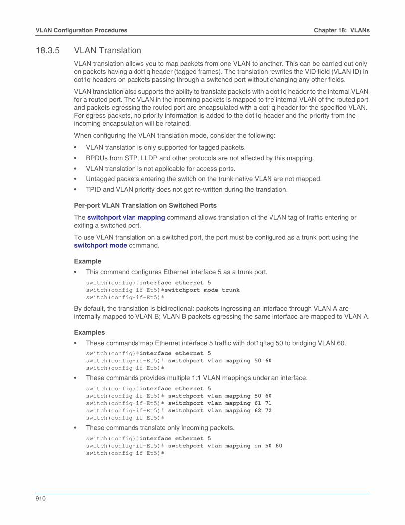
18.3.5 VLAN Translation
VLAN translation allows you to map packets from one VLAN to another. This can be carried out onlyon packets having a dot1q header (tagged frames). The translation rewrites the VID field (VLAN ID) indot1q headers on packets passing through a switched port without changing any other fields.
VLAN translation also supports the ability to translate packets with a dot1q header to the internal VLANfor a routed port. The VLAN in the incoming packets is mapped to the internal VLAN of the routed portand packets egressing the routed port are encapsulated with a dot1q header for the specified VLAN.For egress packets, no priority information is added to the dot1q header and the priority from theincoming encapsulation will be retained.
When configuring the VLAN translation mode, consider the following:
• VLAN translation is only supported for tagged packets.
• BPDUs from STP, LLDP and other protocols are not affected by this mapping.
• VLAN translation is not applicable for access ports.
• Untagged packets entering the switch on the trunk native VLAN are not mapped.
• TPID and VLAN priority does not get re-written during the translation.
Per-port VLAN Translation on Switched Ports
The switchport vlan mapping command allows translation of the VLAN tag of traffic entering orexiting a switched port.
To use VLAN translation on a switched port, the port must be configured as a trunk port using theswitchport mode command.
Example
• This command configures Ethernet interface 5 as a trunk port.
switch(config)#interface ethernet 5switch(config-if-Et5)#switchport mode trunkswitch(config-if-Et5)#
By default, the translation is bidirectional: packets ingressing an interface through VLAN A areinternally mapped to VLAN B; VLAN B packets egressing the same interface are mapped to VLAN A.
Examples
• These commands map Ethernet interface 5 traffic with dot1q tag 50 to bridging VLAN 60.
switch(config)#interface ethernet 5switch(config-if-Et5)# switchport vlan mapping 50 60switch(config-if-Et5)#
• These commands provides multiple 1:1 VLAN mappings under an interface.
switch(config)#interface ethernet 5switch(config-if-Et5)# switchport vlan mapping 50 60switch(config-if-Et5)# switchport vlan mapping 61 71switch(config-if-Et5)# switchport vlan mapping 62 72switch(config-if-Et5)#
• These commands translate only incoming packets.
switch(config)#interface ethernet 5switch(config-if-Et5)# switchport vlan mapping in 50 60switch(config-if-Et5)#

Chapter 18: VLANs VLAN Configuration Procedures
911
• These commands translate only egress packets.
switch(config)#interface ethernet 5switch(config-if-Et5)#switchport vlan mapping out 60 50switch(config-if-Et5)#
Per-port VLAN Translation on Routed Ports
On routed ports, the encapsulation dot1q vlan command (permitted only on routed ports) configuresthe VLAN on the interface to act as the native VLAN. This command will map packets ingressing withthe specified VLAN ID to the internal VLAN ID of the routed port. All traffic egressing out of the routedport will be tagged with the VLAN ID specified in the command.
Examples
• These commands translate between VLAN 50 and the internal VLAN for Ethernet interface 5 (arouted port).
switch(config)#interface ethernet 5switch(config-if-Et5)# no switchportswitch(config-if-Et5)# encapsulation dot1q vlan 50switch(config-if-Et5)#

912
VLAN Configuration Commands Chapter 18: VLANs
18.4 VLAN Configuration CommandsGlobal VLAN Configuration Commands• interface vlan• vlan• vlan internal allocation policy
VLAN Configuration Mode Commands• name (VLAN configuration mode)• state• trunk group
Layer 2 Interface (Ethernet and Port Channel) Configuration Commands• switchport access vlan• switchport mode• switchport trunk allowed vlan• switchport trunk group• switchport trunk native vlan• switchport vlan mapping
VLAN Interface Configuration Mode Commands• autostate• encapsulation dot1q vlan• l2-protocol encapsulation dot1q vlan
Show Commands• show dot1q-tunnel• show interfaces switchport• show interfaces switchport backup• show interfaces trunk• show interfaces vlans• show vlan• show vlan dynamic• show vlan internal allocation policy• show vlan internal usage• show vlan summary• show vlan trunk group

Chapter 18: VLANs VLAN Configuration Commands
913
autostate
When autostate is enabled, the VLAN interface will be up when:
• the corresponding VLAN exists and is in the active state.
• one or more layer 2 ports in the VLAN are up and in spanning-tree forwarding state.
• the VLAN interface exists and is not in a shutdown state.
Autostate is enabled by default. When autostate is disabled, the VLAN interface is forced to be active.
• The no autostate command disables autostate on the configuration mode interface. The noautostate command is stored to running-config.
• The autostate command enables the autostate function on the configuration mode VLAN SVI byremoving the corresponding no autostate statement from running-config.
• The default autostate command restores the autostate default state of enabled by removing thecorresponding no autostate statement from running-config.
Command ModeInterface-VLAN Configuration
Command Syntaxautostateno autostatedefault autostate
GuidelinesAutostate should be disabled on SVIs configured as an MLAG local interface.
Examples• These commands disable autostate on VLAN 100.
switch(config)#interface vlan 100switch(config-if-Vl100)#no autostateswitch(config-if-Vl100)#
• These commands enable autostate on VLAN 100.
switch(config)#interface vlan 100switch(config-if-Vl100)#autostateswitch(config-if-Vl100)#

914
VLAN Configuration Commands Chapter 18: VLANs
encapsulation dot1q vlan
Routed Port VLAN Translation
In the configuration mode for an Ethernet or port channel interface, the encapsulation dot1q vlantranslates packets with a dot1q header to the internal VLAN for a routed port. The VLAN in the incomingpackets is mapped to the internal VLAN of the routed port, and packets egressing the routed port areencapsulated with a dot1q header for the specified VLAN. For egress packets, no priority informationis added to the dot1q header and the priority from the incoming encapsulation will be retained.
Subinterface VLAN Assignment
When used in the configuration mode for an Ethernet or port channel subinterface, however, theencapsulation dot1q vlan command assigns a dot1q tag to the subinterface. Traffic ingressing on theparent interface with that dot1q tag will then be sent to the configured subinterface. See Subinterfacesand Subinterface Configuration for details.
The no encapsulation dot1q vlan and default encapsulation dot1q vlan commands restore thedefault VLAN to the configuration mode interface by removing the corresponding encapsulation dot1qvlan command from running-config.
Command ModeInterface-Ethernet ConfigurationInterface-port-channel ConfigurationSubinterface-Ethernet ConfigurationSubinterface-port-channel Configuration
Command Syntaxencapsulation dot1q vlan vlan_idno encapsulation dot1q vlandefault encapsulation dot1q vlan
Parameters• vlan_id For VLAN translation, the ID of the external VLAN to be translated; for subinterface
configuration, the VLAN of the subinterface. Values range from 1 to 4094.
Example• These commands translate between VLAN 50 and the internal VLAN for Ethernet interface 5 (a
routed port).
switch(config)#interface ethernet 5switch(config-if-Et5)# no switchportswitch(config-if-Et5)# encapsulation dot1q vlan 50switch(config-if-Et5)#
• These commands assign packets ingressing on Ethernet interface 1/1 with VLAN ID 100 toEthernet subinterface 1/1.1.
switch(config)#interface ethernet1/1.1switch(config-if-Et1/1.1)# no switchportswitch(config-if-Et1/1.1)#encapsulation dot1q vlan 100switch(config-if-Et1/1.1)#

Chapter 18: VLANs VLAN Configuration Commands
915
interface vlan
The interface vlan command places the switch in VLAN-interface configuration mode for modifyingparameters of the switch virtual interface (SVI). An SVI provides Layer 3 processing for packets fromall ports associated with the VLAN. There is no physical interface for the VLAN.
When entering configuration mode to modify existing SVIs, the command can specify multipleinterfaces. The command creates an SVI if the specified interface does not exist prior to issuing thecommand. When creating an SVI, the command can only specify a single interface.
The no interface vlan command deletes the specified SVI interfaces from running-config. Thedefault interface vlan commands remove all configuration statements for the specified SVI interfacesfrom running-config without deleting the interfaces.
Command ModeGlobal Configuration
Command Syntaxinterface vlan v_rangeno interface vlan v_rangedefault interface vlan v_range
Parameter• v_range VLAN interfaces (number, range, or comma-delimited list of numbers and ranges).
VLAN number ranges from 1 to 4094.
RestrictionsInternal VLANs: A VLAN interface cannot be created or configured for internal VLAN IDs. The switchrejects any interface vlan command that specifies an internal VLAN ID.
Example• This example creates an SVI for VLAN 12:
switch#configswitch(config)#interface vlan 12switch(config-if-Vl12)#

916
VLAN Configuration Commands Chapter 18: VLANs
l2-protocol encapsulation dot1q vlan
The l2-protocol encapsulation dot1q vlan command enables Layer 2 802.1Q traffic encapsulationon the configuration mode interface for a specified VLAN. The default VLAN for all interfaces is VLAN 1.
The no l2-protocol encapsulation dot1q vlan and default l2-protocol encapsulation dot1q vlancommands disable the specified encapsulation on the configuration mode interface by removing thecorresponding l2-protocol encapsulation dot1q vlan command from running-config.
Command ModeInterface-Ethernet ConfigurationInterface-Port-channel Configuration
Command Syntaxl2-protocol encapsulation dot1q vlan vlan_idno l2-protocol encapsulation dot1q vlandefault l2-protocol encapsulation dot1q vlan
Parameters• vlan_id the ID of the native VLAN. Values range from 1 to 4094.
Example• These commands enable 802.1Q encapsulation of traffic on VLAN 200.
switch(config)#interface ethernet 5/2switch(config-if-Et5/2)#l2-protocol encapsulation dot1q vlan 200switch(s1)(config-if-Et5/2)#show activeinterface Ethernet5/2 l2-protocol encapsulation dot1q vlan 200switch(config-if-Et5/2)#

Chapter 18: VLANs VLAN Configuration Commands
917
name (VLAN configuration mode)
The name command configures the VLAN name. The name can have up to 32 characters. The defaultname for VLAN 1 is default. The default name for all other VLANs is VLANxxxx, where xxxx is theVLAN number. The default name for VLAN 55 is VLAN0055. The show vlan command displays theVLAN name.
The name command accepts all characters except the space.
The no name and default name commands restore the default name by removing the name commandfrom running-config.
Command ModeVLAN Configuration
Command Syntaxname label_textno namedefault name
Parameters• label_text character string assigned to name attribute. Maximum length is 32 characters. The
space character is not permitted in the name string.
Examples• These commands assign corporate_100 as the name for VLAN 25, then displays the VLAN name.
switch(config)#vlan 25switch(config-vlan-25)#name corporate_100switch(config-vlan-25)#show vlan 25VLAN Name Status Ports----- -------------------------------- --------- -------------------------------25 corporate_100 active
switch(config-vlan-25)#

918
VLAN Configuration Commands Chapter 18: VLANs
show dot1q-tunnel
The show dot1q-tunnel command displays the ports that are configured in dot1q-tunnel switchingmode. The switchport mode command configures the switching mode for the configuration modeinterface.
Command ModeEXEC
Command Syntaxshow dot1q-tunnel [INTERFACE]
Parameters• INTERFACE Interface type and numbers. Options include:
• <no parameter> Display information for all interfaces.
• ethernet e_range Ethernet interface range specified by e_range.
• loopback l_range Loopback interface specified by l_range.
• management m_range Management interface range specified by m_range.
• port-channel p_range Port-Channel Interface range specified by p_range.
• vlan v_range VLAN interface range specified by v_range.
• vxlan vx_range VXLAN interface range specified by vx_range.
Valid range formats include number, number range, or comma-delimited list of numbers andranges.
Example• This command displays the ports that are configured in dot1q-tunnel switching mode.
switch>show dot1q-tunneldot1q-tunnel mode LAN Port (s)------------------------------Po4Po21Po22switch>

Chapter 18: VLANs VLAN Configuration Commands
919
show interfaces switchport
The show interfaces switchport command displays the switching configuration and operationalstatus of the specified ports.
Command ModeEXEC
Command Syntaxshow interfaces [INTERFACE] switchport
Parameters• INTERFACE Interface type and numbers. Options include:
• <no parameter> Display the switching status for all interfaces.
• ethernet e_range Ethernet interface range specified by e_range.
• loopback l_range Loopback interface specified by l_range.
• management m_range Management interface range specified by m_range.
• port-channel p_range Port-Channel Interface range specified by p_range.
• vlan v_range VLAN interface range specified by v_range.
Valid e_range, l_range, m_range, p_range, and v_range formats include number, numberrange, or comma-delimited list of numbers and ranges.
Example• This command displays the switching status for all interfaces.
switch(config)#show interface switchportDefault switchport mode: access
Name: Et5/1Switchport: EnabledAdministrative Mode: static accessOperational Mode: static accessMAC Address Learning: enabledAccess Mode VLAN: 1 (default)Trunking Native Mode VLAN: 1 (default)Administrative Native VLAN tagging: disabledTrunking VLANs Enabled: ALLStatic Trunk Groups: Dynamic Trunk Groups:
Name: Et5/2Switchport: EnabledAdministrative Mode: static accessOperational Mode: static accessMAC Address Learning: enabledAccess Mode VLAN: 1 (default)Trunking Native Mode VLAN: 1 (default)Administrative Native VLAN tagging: disabledTrunking VLANs Enabled: ALLStatic Trunk Groups: Dynamic Trunk Groups:
[...]
switch(config)#

920
VLAN Configuration Commands Chapter 18: VLANs
• This command displays the switching status of port channel interfaces 21 and 22.
switch>show interface port-channel 21-22 switchportName: Po21Switchport: EnabledAdministrative Mode: tunnelOperational Mode: tunnelAccess Mode VLAN: 1 (inactive)Trunking Native Mode VLAN: 100 (VLAN0100)Administrative Native VLAN tagging: disabledTrunking VLANs Enabled: ALLTrunk Groups: foo
Name: Po22Switchport: EnabledAdministrative Mode: tunnelOperational Mode: tunnelAccess Mode VLAN: 1 (inactive)Trunking Native Mode VLAN: 1 (inactive)Administrative Native VLAN tagging: disabledTrunking VLANs Enabled: ALLTrunk Groups:
switch>

Chapter 18: VLANs VLAN Configuration Commands
921
show interfaces switchport backup
The show interfaces switchport backup command displays interfaces that are configured asswitchport backup pairs and the operational status of each interface. For each pair, the commanddisplays the names, roles, status, and VLAN traffic of each interface.
Command ModeEXEC
Command Syntaxshow interfaces [INTERFACE] switchport backup
Parameters• INTERFACE Interface type and numbers. Options include:
• <no parameter> Display information for all interfaces.
• ethernet e_range Ethernet interface range specified by e_range.
• loopback l_range Loopback interface specified by l_range.
• management m_range Management interface range specified by m_range.
• port-channel p_range Port-Channel Interface range specified by p_range.
• vlan v_range VLAN interface range specified by v_range.
Valid e_range, l_range, m_range, p_range, and v_range formats include number, numberrange, or comma-delimited list of numbers and ranges.
Display Values• State Operational status of the interface. Values include:
• Up Spanning tree mode is backup, interface status is up.
• Down Spanning tree mode is backup, interface status is down.
• Inactive Configuration The spanning tree mode is not backup.
• Forwarding vlans VLANs forwarded by the interface. Depends on interface operation statusand prefer option specified by the switchport backup command.
Example• This command displays the configured switchport primary-backup pairs.
switch>show interfaces switchport backupSwitch backup interface pair: Ethernet17, Ethernet18Primary Interface: Ethernet17 State: UpBackup Interface: Ethernet18 State: UpEthernet17 forwarding vlans: 1-20Ethernet18 forwarding vlans:
922
VLAN Configuration Commands Chapter 18: VLANs
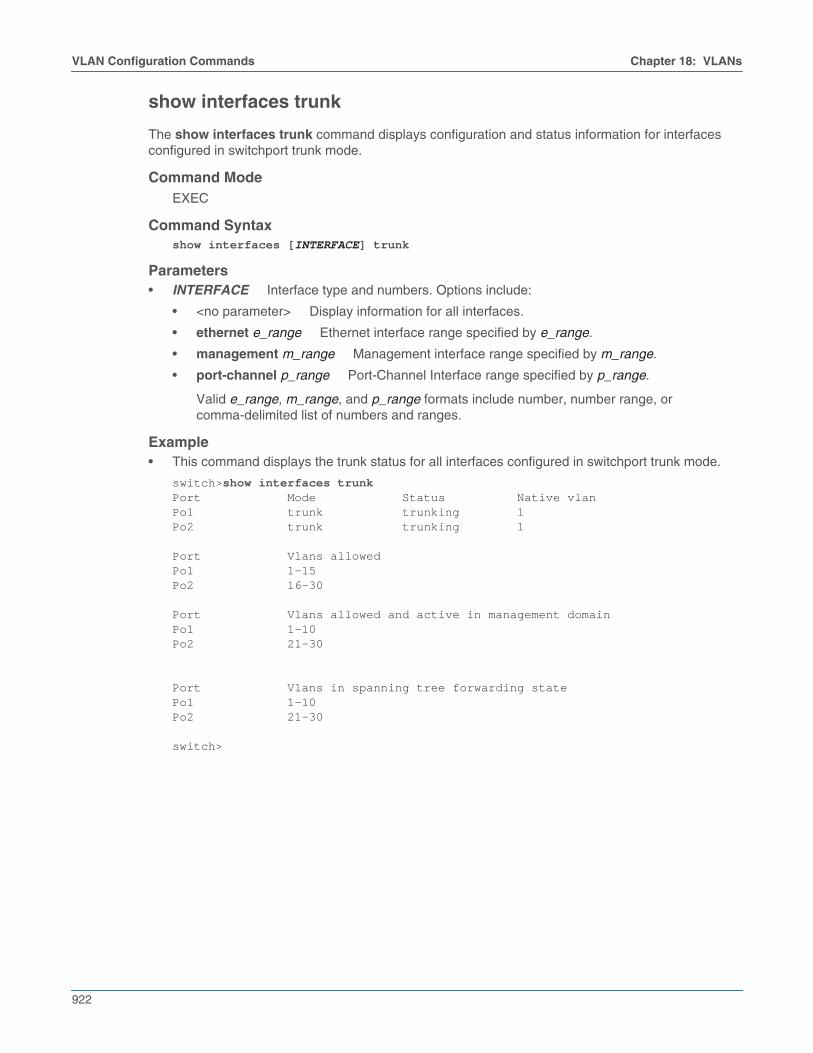
show interfaces trunk
The show interfaces trunk command displays configuration and status information for interfacesconfigured in switchport trunk mode.
Command ModeEXEC
Command Syntaxshow interfaces [INTERFACE] trunk
Parameters• INTERFACE Interface type and numbers. Options include:
• <no parameter> Display information for all interfaces.
• ethernet e_range Ethernet interface range specified by e_range.
• management m_range Management interface range specified by m_range.
• port-channel p_range Port-Channel Interface range specified by p_range.
Valid e_range, m_range, and p_range formats include number, number range, orcomma-delimited list of numbers and ranges.
Example• This command displays the trunk status for all interfaces configured in switchport trunk mode.
switch>show interfaces trunkPort Mode Status Native vlanPo1 trunk trunking 1Po2 trunk trunking 1
Port Vlans allowedPo1 1-15Po2 16-30
Port Vlans allowed and active in management domainPo1 1-10Po2 21-30
Port Vlans in spanning tree forwarding statePo1 1-10Po2 21-30
switch>

Chapter 18: VLANs VLAN Configuration Commands
923
show interfaces vlans
The show interfaces vlans command displays a table that lists the VLANs that are carried by thespecified interfaces. Interfaces that do not carry VLANs are not listed in the table. The table lists theuntagged (native or access) and tagged VLANs for each interface.
Command ModeEXEC
Command Syntaxshow interfaces [INT_NAME] vlans
Parameters• INT_NAME Interface type and number. Values include
• ethernet e_num Ethernet interface specified by e_num.
• management m_num Management interface specified by m_num.
• port-channel p_num Port-Channel Interface specified by p_num.
Example• This command displays the VLANs carried by all L2 ports.
switch>show interfaces vlansPort Untagged TaggedEt9 3910 -Et11 3912 -Et16 500 -Et17 3908 -Et18 3908 -Po1 1 101-102,500,721,3000,Po2 101 -Po4 3902 -Po5 3903 -Po6 3992 -Po7 661 -Po8 3911 -

924
VLAN Configuration Commands Chapter 18: VLANs
show vlan
The show vlan command displays the VLAN ID, name, status, and member ports of all configuredVLANs. The command only displays active ports by default; by specifying configured-ports, thecommand displays all ports that are members of a configured VLAN regardless of their activity status,including Ethernet ports that are members of a port channel.
Command ModeEXEC
Command Syntaxshow vlan [VLAN_LIST] [PORT_ACTIVITY]
Parameters• VLAN_LIST List of VLANs displayed by command. Options include:
• <no parameter> all VLANs.
• v_range VLANs specified by v_range.
• id v_range VLANs specified by v_range.
• name v_name VLANs specified by the VLAN name v_name.
v_range formats include number, number range, or comma-delimited list of numbers and ranges.
• PORT_ACTIVITY Ports listed in table. Options include:
• <no parameter> table displays only active ports (same as active-configuration option).
• active-configuration table displays only active ports.
• configured-ports table displays all configured ports.
Display Values• VLAN The VLAN ID.
• Name The name of the VLAN.
• Status The status of the VLAN.
• Ports The ports that are members of the VLAN.
Example• This command displays status and ports of VLANs 1-1000.
switch>show vlan 1-1000VLAN Name Status Ports----- -------------------------------- --------- -------------------------------1 default active Po1184 fet.arka active Cpu, Po1, Po2262 mgq.net active PPo2, Po1512 sant.test active Cpu, Et16, Po1821 ipv6.net active Cpu, Po1, Po7
switch>
Chapter 18: VLANs VLAN Configuration Commands
925
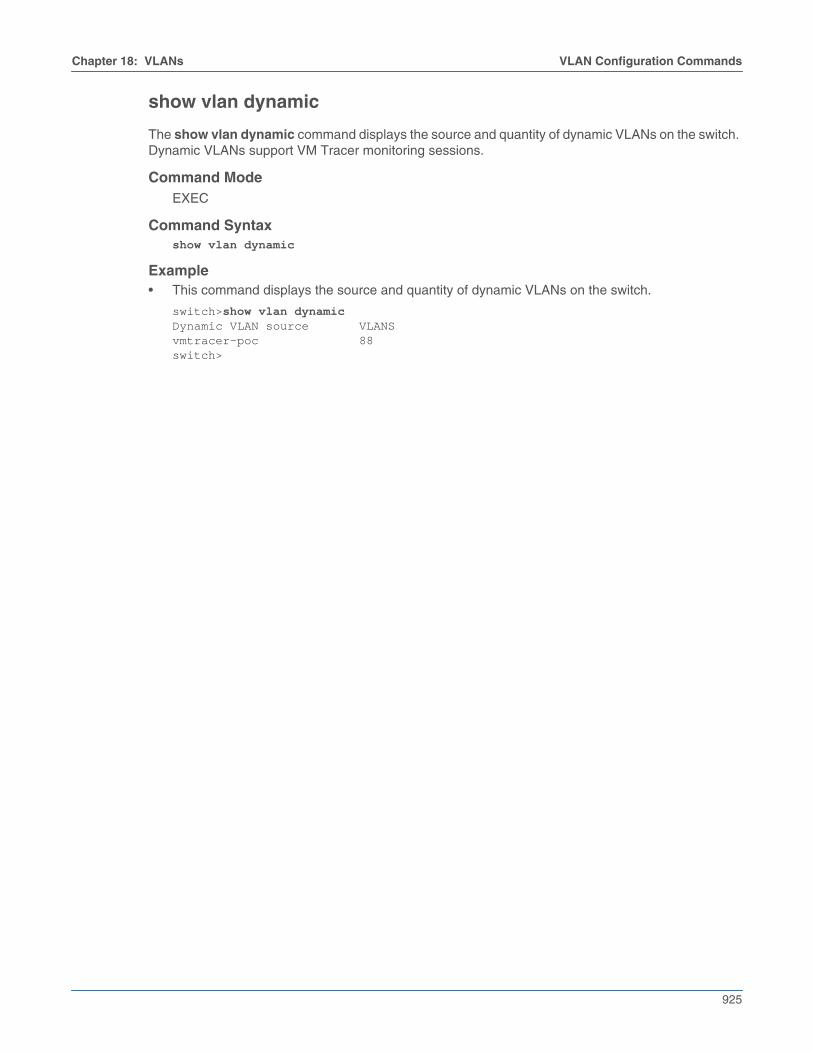
show vlan dynamic
The show vlan dynamic command displays the source and quantity of dynamic VLANs on the switch.Dynamic VLANs support VM Tracer monitoring sessions.
Command ModeEXEC
Command Syntaxshow vlan dynamic
Example• This command displays the source and quantity of dynamic VLANs on the switch.
switch>show vlan dynamicDynamic VLAN source VLANSvmtracer-poc 88switch>

926
VLAN Configuration Commands Chapter 18: VLANs
show vlan internal allocation policy
The show vlan internal allocation policy command displays the method the switch uses to allocateVLANs to routed ports. The vlan internal allocation policy command configures the allocationmethod.
The allocation method consists of two configurable components:
• range: the list of VLANs that are allocated to routed ports.
• direction: the direction by which VLANs are allocated (ascending or descending).
Command ModeEXEC
Command Syntaxshow vlan internal allocation policy
Example• This command displays the internal allocation policy.
switch>show vlan internal allocation policyInternal VLAN Allocation Policy: ascendingInternal VLAN Allocation Range: 1006-4094switch>
Chapter 18: VLANs VLAN Configuration Commands
927
show vlan internal usage
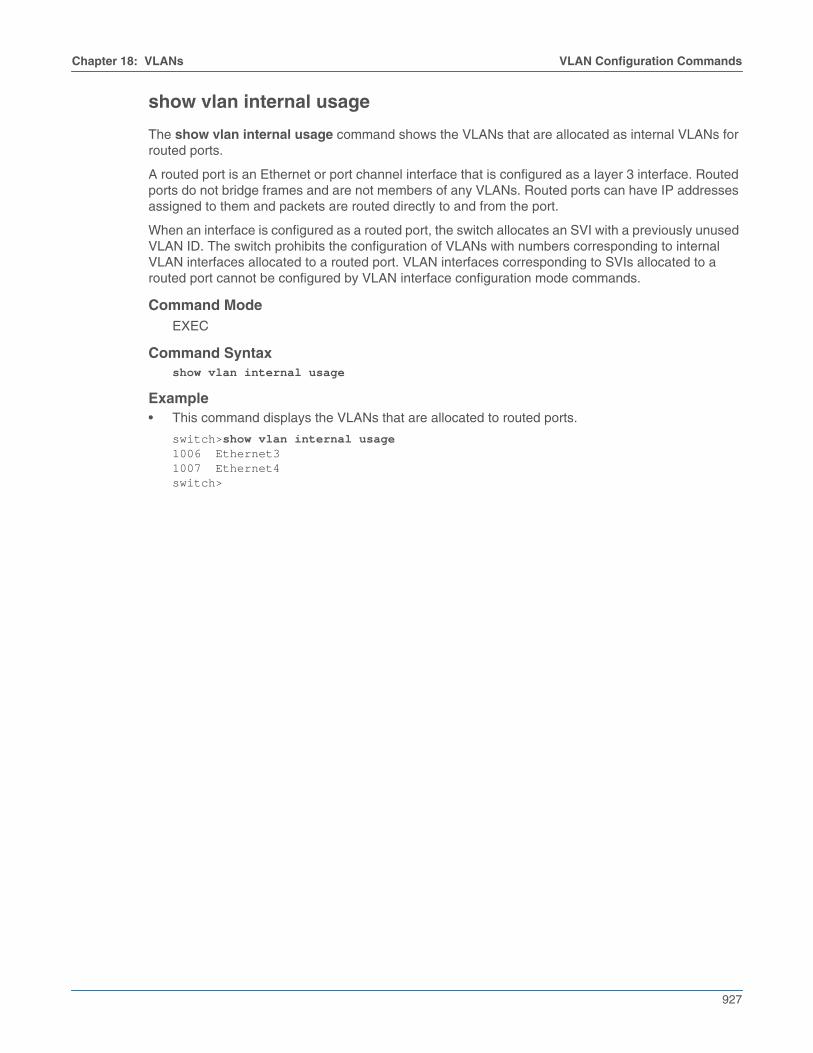
The show vlan internal usage command shows the VLANs that are allocated as internal VLANs forrouted ports.
A routed port is an Ethernet or port channel interface that is configured as a layer 3 interface. Routedports do not bridge frames and are not members of any VLANs. Routed ports can have IP addressesassigned to them and packets are routed directly to and from the port.
When an interface is configured as a routed port, the switch allocates an SVI with a previously unusedVLAN ID. The switch prohibits the configuration of VLANs with numbers corresponding to internalVLAN interfaces allocated to a routed port. VLAN interfaces corresponding to SVIs allocated to arouted port cannot be configured by VLAN interface configuration mode commands.
Command ModeEXEC
Command Syntaxshow vlan internal usage
Example• This command displays the VLANs that are allocated to routed ports.
switch>show vlan internal usage1006 Ethernet31007 Ethernet4switch>

928
VLAN Configuration Commands Chapter 18: VLANs
show vlan summary
The show vlan summary command displays the number of VLANs that are configured on the switch.
Command ModeEXEC
Command Syntaxshow vlan summary
Example• This command displays the number of VLANs on the switch.
switch>show vlan summaryNumber of existing VLANs : 18
switch>

Chapter 18: VLANs VLAN Configuration Commands
929
show vlan trunk group
The show vlan trunk group command displays the trunk group membership of the specified VLANs.
Command ModeEXEC
Command Syntaxshow vlan [VLAN_LIST] trunk group
Parameters• VLAN_LIST VLAN list. Options include:
• <no parameter> all VLANs.
• v_range VLANs specified by v_range.
• id v_range VLANs specified by v_range.
• name v_name VLANs specified by the VLAN name v_name.
Display Values• VLAN VLAN ID.
• Trunk Groups Trunk groups associated with the listed VLANs.
Example• This command displays the trunk group membership of all configured VLANs.
switch>show vlan trunk groupVLAN Trunk Groups---- ----------------------------------------------------------------------510 first_group1240 second_group100 third_group101 middle_group102200
switch>
930
VLAN Configuration Commands Chapter 18: VLANs
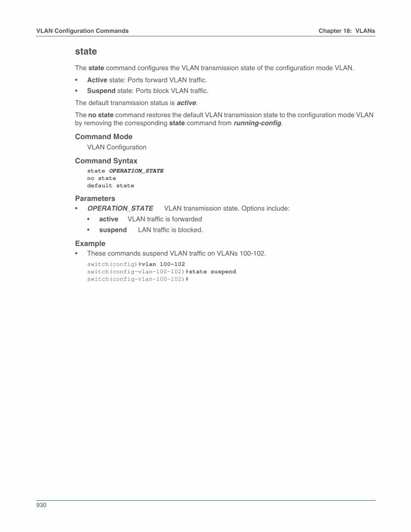
state
The state command configures the VLAN transmission state of the configuration mode VLAN.
• Active state: Ports forward VLAN traffic.
• Suspend state: Ports block VLAN traffic.
The default transmission status is active.
The no state command restores the default VLAN transmission state to the configuration mode VLANby removing the corresponding state command from running-config.
Command ModeVLAN Configuration
Command Syntaxstate OPERATION_STATEno statedefault state
Parameters• OPERATION_STATE VLAN transmission state. Options include:
• active VLAN traffic is forwarded
• suspend LAN traffic is blocked.
Example• These commands suspend VLAN traffic on VLANs 100-102.
switch(config)#vlan 100-102switch(config-vlan-100-102)#state suspendswitch(config-vlan-100-102)#

Chapter 18: VLANs VLAN Configuration Commands
931
switchport dot1q ethertype
The switchport dot1q ethertype command configures the tag protocol identifier (TPID, also knownas a dot1q ethertype), of the configuration mode interface. By default, all switch ports use the standardTPID of 0x8100.
The no switchport dot1q ethertype and default switchport dot1q ethertype commands restore theTPID to 0x8100 by removing the corresponding switchport dot1q ethertype statement fromrunning-config.
Command ModeInterface-Ethernet Configuration
Command Syntaxswitchport dot1q ethertype ethertypeno switchport dot1q ethertypedefault switchport dot1q ethertype
Parameters• ethertype ethertype number (TPID). Value ranges from 0x600 (1536) through 0xFFFF (65535),
and can be entered in decimal or hexadecimal notation. Value is stored and displayed inhexadecimal form; the default value is 0x8100.
Example• These commands configure 0x9100 as the TPID of Ethernet interface 5.
switch(config)#interface ethernet 5switch(config-if-Et5)#switchport dot1q ethertype 0x9100switch(config-if-Et5)#

932
VLAN Configuration Commands Chapter 18: VLANs
switchport access vlan
The switchport access vlan command specifies the access VLAN of the configuration modeinterface. Ethernet or port channel interfaces that are in access mode are members of only the accessVLAN. Untagged frames that the interface receives are associated with the access VLAN. Framestagged with the access VLAN are also associated with the access VLAN. The interface drops all othertagged frames that it receives. By default, VLAN 1 is the access VLAN of all Ethernet and port channelinterfaces.
An interface's access mode is effective only when the interface is in access mode or dot1q-tunnelmode, as specified by the switchport mode command. Interfaces in dot1q-tunnel mode handle inboundtraffic as untagged traffic and associate all traffic with the access VLAN. Interfaces configured toswitchport trunk mode maintain and ignore existing switchport access commands.
The no switchport access vlan and default switchport access vlan commands restore VLAN 1 asthe access VLAN of the configuration mode interface by removing the corresponding switchportaccess vlan statement from running-config.
Command ModeInterface-Ethernet ConfigurationInterface-Port-channel Configuration
Command Syntaxswitchport access vlan v_numno switchport access vlandefault switchport access vlan
Parameters• v_num number of access VLAN. Value ranges from 1 to 4094. Default is 1.
Example• These commands assign VLAN 100 as the access VLAN to Ethernet interface 5.
switch(config)#interface ethernet 5switch(config-if-Et5)#switchport access vlan 100switch(config-if-Et5)#

Chapter 18: VLANs VLAN Configuration Commands
933
switchport mode
The switchport mode command specifies the switching mode of the configuration mode interface. Theswitch supports five switching modes: access, trunk, dot1q-tunnel, tap, and tool.
• Access switching mode: The interface is a member of one VLAN, called the access VLAN, asspecified by the switchport access vlan command. Tagged frames received on the interface aredropped unless they are tagged with the access VLAN. Frames transmitted from the interface arealways untagged.
• Trunk switching mode: The interface may be a member of multiple VLANs, as configured by theswitchport trunk allowed vlan command. Untagged traffic is associated with the interface'snative VLAN, as configured with the switchport trunk native vlan command.
• Dot1q-tunnel switching mode: The interface treats all inbound packets as untagged traffic andhandles them as traffic of its access VLAN, as specified by the switchport access vlan command.
• Tap mode: The interface operates as a tap port. Tap ports receive traffic for replication on one ormore tool ports.The interface may be a member of multiple VLANs, as configured by theswitchport tap allowed vlan command. Untagged traffic is associated with the interface's nativeVLAN, as configured with the switchport tap native vlan command.
Tap ports are in STP forwarding state and prohibit egress traffic. MAC learning, control planeinteraction and traps for inbound traffic are disabled.
• Tool mode: The interface operates as a tool port. Tool ports replicate traffic received by tap ports.The interface may be a member of multiple VLANs, as configured by the switchport tool allowedvlan command. MAC learning, control plane interaction and traps for inbound traffic are disabled.
Tool ports are in STP forwarding state and prohibit ingress traffic that uses port settings.
The status of switchport configured ports depends on the switch’s tap aggregation mode (which canbe viewed by using the mode (tap-agg configuration mode) command):
• tap aggregation mode enabled: tap and tool ports are enabled. Switching ports are errdisabled.
• tap aggregation mode disabled: tap and tool ports are errdisabled. Switching ports are enabled.
The no switchport mode and default switchport mode commands return the configuration modeinterface to its default setting as an access port by deleting the corresponding switchport modecommand from running-config.
Command ModeInterface-Ethernet ConfigurationInterface-Port-channel Configuration
Command Syntaxswitchport mode MODE_TYPEno switchport modedefault switchport mode
Parameters• MODE_TYPE switching mode of the configuration mode interfaces. Options include:
• access access switching mode.
• dot1q-tunnel dot1q-tunnel switching mode.
• tap tap switching mode.
• tool tool switching mode.
• trunk trunk switching mode.

934
VLAN Configuration Commands Chapter 18: VLANs
RestrictionsDot1q-tunnel switching mode is not available on Petra platform switches.
Tap aggregation (tap and tool modes) is available on FM6000 and Arad platform switches.
Example• These commands configure Ethernet 4 interface as a trunk port.
switch(config)#interface ethernet 4switch(config-if-Et4)#switchport mode trunkswitch(config-if-Et4)#

Chapter 18: VLANs VLAN Configuration Commands
935
switchport trunk allowed vlan
The switchport trunk allowed vlan command creates or modifies the list of VLANs for which theconfiguration mode interface, in trunk mode, handles tagged traffic. By default, interfaces handletagged traffic for all VLANs. Command settings persist in running-config without taking effect whenthe switch is in tap aggregation mode or the interface is not in trunk mode.
The no switchport trunk allowed vlan and default switchport trunk allowed vlan commandsrestore the trunk mode default allowed VLAN setting of all by removing the corresponding switchporttrunk allowed vlan statement from running-config.
Command ModeInterface-Ethernet ConfigurationInterface-Port-channel Configuration
Command Syntaxswitchport trunk allowed vlan EDIT_ACTIONno switchport trunk allowed vlandefault switchport trunk allowed vlan
Parameters• EDIT_ACTION modifications to the VLAN list.
• v_range Creates VLAN list from v_range.
• add v_range Adds specified VLANs to current list.
• all VLAN list contains all VLANs.
• except v_range VLAN list contains all VLANs except those specified.
• none VLAN list is empty (no VLANs).
• remove v_range Removes specified VLANs from current list.
Valid v_range formats include number, range, or comma-delimited list of numbers and ranges.
Example• These commands create the trunk mode allowed VLAN list of 6-10 for Ethernet interface 14, then
verifies the VLAN list.
switch(config)#interface ethernet 14switch(config-if-Et14)#switchport trunk allowed vlan 6-10switch(config-if-Et14)#show interfaces ethernet 14 switchportName: Et14Switchport: EnabledAdministrative Mode: trunkOperational Mode: trunkAccess Mode VLAN: 1 (inactive)Trunking Native Mode VLAN: 1 (inactive)Administrative Native VLAN tagging: disabledTrunking VLANs Enabled: 6-10Trunk Groups:
switch(config-if-Et14)#

936
VLAN Configuration Commands Chapter 18: VLANs
switchport trunk group
The switchport trunk group command assigns the configuration mode interface to the specified trunkgroup. Trunk group ports handle traffic of the VLANs assigned to the group.
The no switchport trunk group and default switchport trunk group commands remove theconfiguration mode interface from the specified trunk group by deleting the corresponding statementfrom running-config. If the command does not specify a trunk group, the interface is removed from alltrunk groups to which it is assigned.
Note On platforms which support the use of port channels as mirror destinations, a port channel which isbeing used as a mirror destination must not be assigned to an MLAG.
Command ModeInterface-Ethernet ConfigurationInterface-Port-channel Configuration
Command Syntaxswitchport trunk group group_nameno switchport trunk group [group_name]default switchport trunk group [group_name]
Parameters• group_name trunk group name.
Example• These commands assign port channel 4 to trunk group fe-1.
switch(config)#interface port-channel 4switch(config-if-Po4)#switchport trunk group fe-1switch(config-if-Po4)#

Chapter 18: VLANs VLAN Configuration Commands
937
switchport trunk native vlan
The switchport trunk native vlan command specifies the trunk mode native VLAN for theconfiguration mode interface. Interfaces in trunk mode associate untagged frames with the nativeVLAN. Trunk mode interfaces can also be configured to drop untagged frames. The default nativeVLAN for all interfaces is VLAN 1.
The no switchport trunk native vlan and default switchport trunk native vlan commands restoreVLAN 1 as the trunk mode native VLAN to the configuration mode interface by removing thecorresponding switchport trunk native vlan command from running-config.
Command ModeInterface-Ethernet ConfigurationInterface-Port-channel Configuration
Command Syntaxswitchport trunk native vlan VLAN_IDno switchport trunk native vlandefault switchport trunk native vlan
Parameters• VLAN_ID the ID of the native VLAN. Options include
• v_num VLAN number. Value ranges from 1 to 4094
• tag interface drops all untagged frames.
Example• These commands configure VLAN 100 as the native VLAN for port channel 21.
switch(config)#interface port-channel 21switch(config-if-Po21)#switchport trunk native vlan 100switch(config-if-Po21)#

938
VLAN Configuration Commands Chapter 18: VLANs
switchport vlan mapping
The switchport vlan mapping command allows you to map packets from one VLAN to another usingVLAN translation. This can be carried out only on packets having a dot1q header (tagged frames). Thetranslation rewrites the VID field (VLAND ID) in dot1q headers on packets passing through a switchedport without changing any other fields.
By default, the translation is bidirectional: packets ingressing an interface through VLAN A areinternally mapped to VLAN B; VLAN B packets egressing the same interface are mapped to VLAN A.
To use VLAN translation on a switched port, the port must be configured as a trunk port using theswitchport mode command.
VLAN translation on routed ports is accomplished through the encapsulation dot1q vlan command.
The no switchport vlan mapping and default switchport vlan mapping commands remove VLANmapping by removing the switchport vlan mapping command from running-config.
Command ModeInterface-Ethernet ConfigurationInterface-Port-channel Configuration
Command Syntaxswitchport vlan mapping [DIRECTION] incoming_vlanid new_vlanidno switchport vlan mapping incoming_vlanid new_vlanidno switchport vlan mapping DIRECTION incoming_vlaniddefault switchport vlan mapping incoming_vlanid new_vlaniddefault switchport vlan mapping DIRECTION incoming_vlanid
Parameters• DIRECTION transmission direction of traffic to be translated.
• <no parameter> translates the specified VLAN IDs for transmitted and received traffic.
• in translates the specified VLAN IDs for received traffic only.
• out translates the specified VLAN IDs for transmitted traffic only.
• incoming_vlanid The VLAN ID to be translated. Value ranges from 1 to 4094.
• new_vlanid The new VLAN ID or bridging VLAN ID which will be used internally. Value rangesfrom 1 to 4094.
Example• These commands translate only incoming packets, changing the VID to 2008 in the dot1q header
of packets ingressing on VLAN 201.
switch(config)# interface ethernet 5switch(config-if-Et5)# switchport vlan mapping in 201 2008 switch(config-if-Et5)#
• These commands translate multiple VLAN mappings under an interface.
switch(config)#interface ethernet 5switch(config-if-Et5)# switchport vlan mapping 50 60switch(config-if-Et5)# switchport vlan mapping 61 71switch(config-if-Et5)# switchport vlan mapping 62 72switch(config-if-Et5)#

Chapter 18: VLANs VLAN Configuration Commands
939
trunk group
The trunk group command assigns the configuration mode VLAN to a specified trunk group.
A trunk group is the set of physical interfaces that comprise the trunk and the collection of VLANswhose traffic is carried on the trunk. The traffic of a VLAN that belongs to one or more trunk groups iscarried only on ports that are members of trunk groups to which the VLAN belongs. Switchportcommands specify the physical interfaces that carry trunk group traffic.
The no trunk group and default trunk group commands remove the configuration mode VLAN fromthe specified trunk group by removing the corresponding trunk group statement from running-config.If a trunk group is not specified, the commands remove the configuration mode VLAN from all trunkgroups.
Command ModeVLAN Configuration
Command Syntaxtrunk group nameno trunk group [name]default trunk group [name]
Parameters• name a name representing the trunk group.
Example• These commands assigns VLAN 49 to the trunk group mlagpeer:
switch(config)#vlan 49switch(config-vlan-49)#trunk group mlagpeerswitch(config-vlan-49)#

940
VLAN Configuration Commands Chapter 18: VLANs
vlan
The vlan command places the switch in VLAN configuration mode to configure a set of virtual LANs.The command creates the specified VLANs if they do not exist prior to issuing the command. A VLANthat is in use as an internal VLAN may not be created or configured. The switch rejects any vlancommand that specifies an internal VLAN ID.
The default vlan and no vlan commands removes the VLAN statements from running-config for thespecified VLANs.
The exit command returns the switch to global configuration mode.
Command ModeGlobal Configuration
Command Syntaxvlan vlan_rangeno vlan vlan_rangedefault vlan vlan_range
Parameters• vlan_range VLAN list.
Formats include a name, number, number range, or comma-delimited list of numbers and ranges.
Commands Available in VLAN configuration mode• name (VLAN configuration mode)
• state
• trunk group
GuidelinesIn MLAG configurations, VLANs operate as follows:
• The VLAN must be configured identically on both MLAG peer switches.
• The port-specific bridging configuration originates on the switch where the port is physicallylocated. This configuration includes the switchport access VLAN, switchport mode (trunk oraccess), trunk-allowed VLANs, the trunk native VLAN, and the switchport trunk groups.
Example• This command creates VLAN 49 and enters VLAN configuration mode for the new VLAN:
switch(config)#vlan 49switch(config-vlan-49)#

Chapter 18: VLANs VLAN Configuration Commands
941
vlan internal allocation policy
The vlan internal allocation policy command specifies the range that the switch can allocate asinternal VLANs when configuring routed ports and the order of their allocation. By default, the switchallocates VLANs in ascending order from VLAN 1006 to VLAN 4094.
The no vlan internal allocation policy and default vlan internal allocation policy commands revertthe policy to its default.
Command ModeGlobal Configuration
Command Syntaxvlan internal allocation policy DIRECTION [RANGE_VLAN]no vlan internal allocation policydefault vlan internal allocation policy
Parameters• DIRECTION VLAN allocation number direction. Options include:
• ascending allocates internal VLANs from lower VLAN bound to upper VLAN bound.
• descending allocates internal VLAN from upper VLAN bound to lower VLAN bound.
• RANGE_VLAN allocation range. Options include:
• <no parameter> 1006 (lower bound) to 4094 (upper bound).
• range lower upper specifies lower bound (lower) and upper bound (upper).
Examples• This command configures the switch to allocate internal VLANS from 3000 through 3999.
switch(config)#vlan internal allocation policy ascending range 3000 3999switch(config)#
• This command configures the switch to allocate internal VLANS from 4094 through 1006.
switch(config)#vlan internal allocation policy descendingswitch(config)#
• This command configures the switch to allocate internal VLANS from 4094 down through 4000.
switch(config)#vlan internal allocation policy descending range 4000 4094switch(config)#
• This command reverts the allocation policy to its default (ascending, between 1006 and 4094).
switch(config)#no vlan internal allocation policyswitch(config)#

942
VLAN Configuration Commands Chapter 18: VLANs