chapter 17: the global positioning systemn0gsg.com/ecfp/ch17_sample.pdf© 2017 tom a. wheeler....
TRANSCRIPT

© 2017 Tom A. Wheeler. Sample for Evaluation. WWW.N0GSG.COM/ECFP 690
Chapter 17: The Global Positioning System
Chapter 17 Objectives At the conclusion of this chapter, the reader will be able to: Since the beginning of recorded history, humans have been intensely interested in
knowing where they are, and where they are going. The earliest people probably used stones, logs, or other objects as markers to guide people from place to place. Of course, these markers could be covered by snow, washed away by floods, or tampered with by enemies -- and at sea, you couldn't use markers like these at all!
One thing that was relatively constant is the position of the stars, and for a long period of time, the only way of navigating by sea was to use them. Navigating by stars required special skills, was only accurate within a mile or two, and only worked at night under a clear sky. This was hardly good enough when a ship was looking for a safe harbor on a stormy night! The use of lighted beacons and buoys certainly helped, but these devices required maintenance. Buoys could be washed out of position in storms.
The first electronic navigation systems were developed during World War II. Among these was the long-range navigation or LORAN system. LORAN transmitters were located along coastal areas, and each LORAN transmitter sent a special timing signal on a LF (below 300 kHz) frequency. A LORAN receiver tuned to three LORAN transmitters and by doing a little arithmetic, it computed its position. LORAN worked only in areas where transmitters have been set up, and was not very accurate, especially in a moving vehicle; errors of 10 miles were common. However, LORAN represented a great advance over previous navigation methods.
The United States has been studying space-based navigation since the 1960s. One of the early successful satellite positioning systems was TRANSIT, the Navy Navigation Satellite System, which was released for commercial use in 1967. Unfortunately, TRANSIT satellites are in a low earth orbit, and their transmission frequencies of 150 MHz and 400 MHz are fairly susceptible to ionospheric interference. TRANSIT satellites are visible for only about 20 minutes, and a position fix can be obtained once every 1 to 3 hours.
The global positioning system, or GPS, is the first system designed to provide world-wide, continuous, and highly accurate navigation coverage. It was developed by the US Department of Defense, and consists of a nominal array of 24 orbiting satellites. (There are actually more than 24 active satellites at present, but only 24 are required for a fully-functioning system.) Because of the large number of available satellites, a user can get a position reading at any time, in any location on the globe.
A GPS receiver gives the end user three important pieces of information. First, the receiver derives an accurate value for time, which is based upon the atomic clocks in the satellites. Second, the receiver gives the three-dimensional position (latitude, longitude,
• Describe briefly the history of navigation. • Explain the orbital parameters of satellites using Kepler's laws. • List and explain the three segments of the current GPS system. • Identify navigation signals. • Define essential GPS terminology. • Describe the operation of various types of GPS receivers. • Explain how position is determined. • Interpret correction methods as they relate to accuracy of position. • Use simple handheld GPS navigational devices. • Describe civilian applications for GPS. • Troubleshoot civilian GPS installations.

© 2017 Tom A. Wheeler. Sample for Evaluation. WWW.N0GSG.COM/ECFP 691
and altitude), which what most users desire. Finally, by doing a little arithmetic with subsequent position readings, a GPS receiver can report speed or velocity.
The possible applications of GPS are endless. Civilians have access to the C/A (Coarse/Acquisition) code channel, and use GPS during hiking, boating, and other outdoor activities. General Motors uses GPS as part of their OnStar system, which includes a GPS receiver in the automobile -- which is linked to a cellular phone. In the event of a serious accident (detected by in-car sensors), the OnStar system automatically dispatches help to the scene.
The military uses GPS for precise navigation and uses the P (Precision) Code channel. The P code channel operates at a much higher data rate than the civilian C/A channel, and in theory offers better accuracy than the C/A code. Advances in receiver design (such as differential GPS techniques) have diminished the accuracy difference between the C/A and P code channels. The P channel information can be encrypted (it is then referred to as the Y channel), and under this condition it cannot be demodulated by the general public. This would likely occur in a time of war (but could occur at any time), so that enemies would be denied access to precision navigation services.
GPS chipsets have fallen in price (they're now less than $10 thanks to the cellular phone industry) are now incorporated into a wide variety of devices. In addition, the combination of GPS data received from satellites and information from mapping databases allows anyone to get real-time map and navigation instructions at the push of a button. This technology would have been considered either science fiction or magic a century ago!
17-1 Satellites and Orbits
All satellite communication systems rely upon one or more space vehicles, or satellites that are made to orbit the earth in predetermined way. With GPS satellites this is especially important, for it is important to be able to accurately calculate the position of each satellite. The motion of satellites, planets and other bodies in space can be described by Kepler's laws of planetary motion.
Johannes Kepler published the first two of these laws in 1609, and the third nearly a
decade later, in 1618. His laws are as follows:
1. A planet describes an ellipse in its orbit around the Sun, with the Sun at one focus. 2. A ray directed from the Sun to a planet sweeps out equal areas in equal times. 3. The square of the period of a planet's orbit p is proportional to the cube of its semimajor
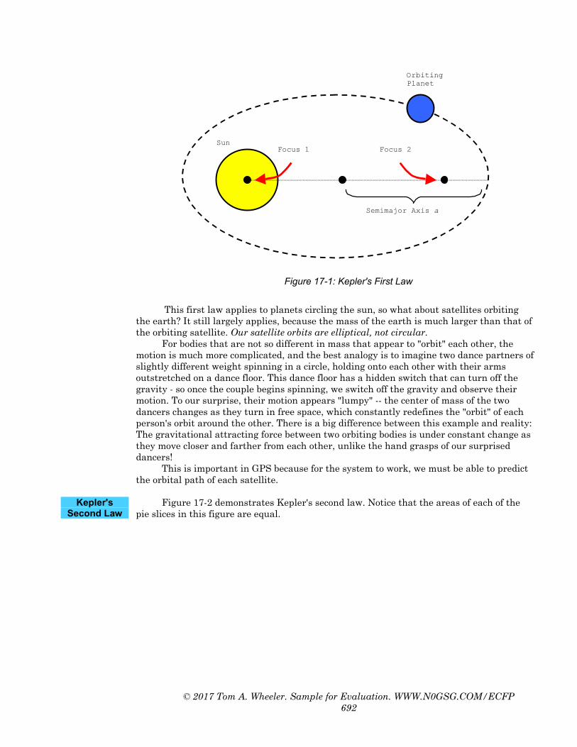
axis a (p2 ∝ a3). (Note that the symbol "∝" means "is proportional to.") Kepler's first law is illustrated in Figure 17-1. What it tells us is that planetary
orbits are elliptical or oval shapes. Most people think that orbits are perfectly round or circular, but that's only approximately true; for celestial objects, a circle does not adequately describe the positions of the orbiting masses.
Kepler's Laws of Planetary
Motion
Kepler's First Law
© 2017 Tom A. Wheeler. Sample for Evaluation. WWW.N0GSG.COM/ECFP 692
Focus 1 Focus 2
OrbitingPlanet
Sun
Semimajor Axis a
Figure 17-1: Kepler's First Law
This first law applies to planets circling the sun, so what about satellites orbiting
the earth? It still largely applies, because the mass of the earth is much larger than that of the orbiting satellite. Our satellite orbits are elliptical, not circular.
For bodies that are not so different in mass that appear to "orbit" each other, the motion is much more complicated, and the best analogy is to imagine two dance partners of slightly different weight spinning in a circle, holding onto each other with their arms outstretched on a dance floor. This dance floor has a hidden switch that can turn off the gravity - so once the couple begins spinning, we switch off the gravity and observe their motion. To our surprise, their motion appears "lumpy" -- the center of mass of the two dancers changes as they turn in free space, which constantly redefines the "orbit" of each person's orbit around the other. There is a big difference between this example and reality: The gravitational attracting force between two orbiting bodies is under constant change as they move closer and farther from each other, unlike the hand grasps of our surprised dancers!
This is important in GPS because for the system to work, we must be able to predict the orbital path of each satellite.
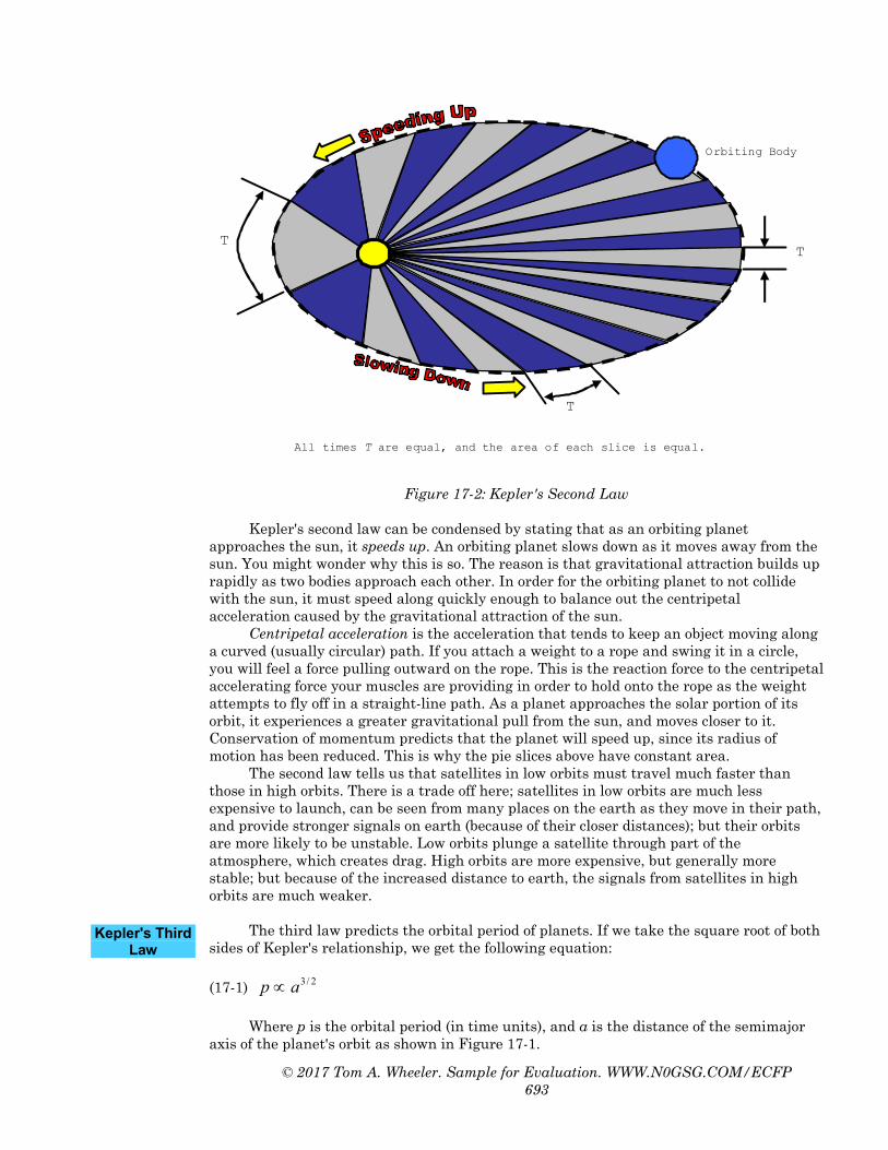
Figure 17-2 demonstrates Kepler's second law. Notice that the areas of each of the
pie slices in this figure are equal.
Kepler's Second Law
© 2017 Tom A. Wheeler. Sample for Evaluation. WWW.N0GSG.COM/ECFP 693
T
All times T are equal, and the area of each slice is equal.
T
T
Orbiting Body
Figure 17-2: Kepler's Second Law
Kepler's second law can be condensed by stating that as an orbiting planet
approaches the sun, it speeds up. An orbiting planet slows down as it moves away from the sun. You might wonder why this is so. The reason is that gravitational attraction builds up rapidly as two bodies approach each other. In order for the orbiting planet to not collide with the sun, it must speed along quickly enough to balance out the centripetal acceleration caused by the gravitational attraction of the sun.
Centripetal acceleration is the acceleration that tends to keep an object moving along a curved (usually circular) path. If you attach a weight to a rope and swing it in a circle, you will feel a force pulling outward on the rope. This is the reaction force to the centripetal accelerating force your muscles are providing in order to hold onto the rope as the weight attempts to fly off in a straight-line path. As a planet approaches the solar portion of its orbit, it experiences a greater gravitational pull from the sun, and moves closer to it. Conservation of momentum predicts that the planet will speed up, since its radius of motion has been reduced. This is why the pie slices above have constant area.
The second law tells us that satellites in low orbits must travel much faster than those in high orbits. There is a trade off here; satellites in low orbits are much less expensive to launch, can be seen from many places on the earth as they move in their path, and provide stronger signals on earth (because of their closer distances); but their orbits are more likely to be unstable. Low orbits plunge a satellite through part of the atmosphere, which creates drag. High orbits are more expensive, but generally more stable; but because of the increased distance to earth, the signals from satellites in high orbits are much weaker.
The third law predicts the orbital period of planets. If we take the square root of both
sides of Kepler's relationship, we get the following equation:
(17-1) 2/3ap ∝
Where p is the orbital period (in time units), and a is the distance of the semimajor axis of the planet's orbit as shown in Figure 17-1.
Kepler's Third Law

© 2017 Tom A. Wheeler. Sample for Evaluation. WWW.N0GSG.COM/ECFP 694
What Equation 17-1 tells us is that the orbital period of a satellite (the time that it
takes to complete one orbital round-trip) increases as the height of a satellite is increased, but not in linear proportion (the exponent is 3/2 in Equation 17-1). We control the orbital period of a satellite by controlling the height of its orbit.
There are three primary types of satellite orbits, as shown below in Figure 17-3.
These are polar, inclined, and equatorial.
a) Polar b) Inclined c) Equatorial
Figure 17-3: Types of Orbits
Polar orbits are used for low-flying satellite missions such as reconaissance. In such
an orbit, the satellite flies over both poles. The satellite path looks like a string that is being wrapped around a slowly-turning ball. The exact track (and thus the positions "seen" on earth by the satellite) depend on the orbital altitude.
Inclined orbits are used for communications work where coverage is needed mainly around the earth's middle regions, and continuous communication is not needed. GPS satellites use this type of orbit.
Equatorial orbits are used for geostationary satellites. You'll recall that Kepler's third law predicts the orbital period of a satellite in terms of the length of its semimajor axis. For earth satellites, an altitude of 22,300 miles leads to a geostationary orbit, where the satellite takes 24 hours to make one round trip. When placed over the equator in such an orbit, the satellite appears fixed at a point in space, which makes it immensely useful for long-distance communications. About 40% of the earth can be covered by one geostationary satellite; three such satellites can cover about 95% of the earth's surface (the polar regions are hard to reach.)
The equatorial orbit locations are prime real estate. They were originally spaced every 4 degrees, for (360/4) or 90 "parking spaces." Improvements in technology have resulted in a decrease to 2 degree spaces, and 1 degree spaces are not far off.
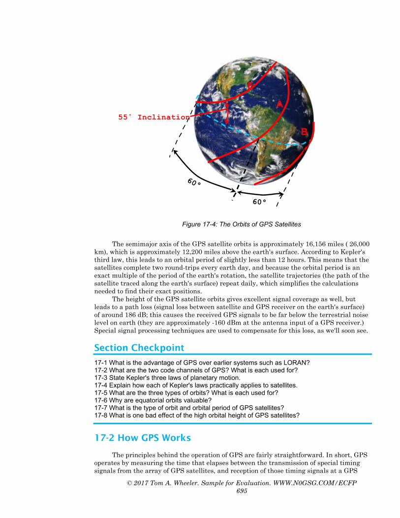
GPS satellites are placed in orbits that are at 55 degrees inclination with respect to
the equator. These satellites orbit within six equally-spaced planes (labeled A through F), which appear as overlapping rings circling the globe as shown below in Figure 17-4. There are nominally four satellites in each of these six planes, but they are not equally spaced in order to optimize world-wide visibility.◦○˚
Types of Orbits
Orbits of GPS Satellites
© 2017 Tom A. Wheeler. Sample for Evaluation. WWW.N0GSG.COM/ECFP 695
F
A
B
60° 60°
55˚ Inclination
Figure 17-4: The Orbits of GPS Satellites
The semimajor axis of the GPS satellite orbits is approximately 16,156 miles ( 26,000
km), which is approximately 12,200 miles above the earth's surface. According to Kepler's third law, this leads to an orbital period of slightly less than 12 hours. This means that the satellites complete two round-trips every earth day, and because the orbital period is an exact multiple of the period of the earth's rotation, the satellite trajectories (the path of the satellite traced along the earth's surface) repeat daily, which simplifies the calculations needed to find their exact positions.
The height of the GPS satellite orbits gives excellent signal coverage as well, but leads to a path loss (signal loss between satellite and GPS receiver on the earth's surface) of around 186 dB; this causes the received GPS signals to be far below the terrestrial noise level on earth (they are approximately -160 dBm at the antenna input of a GPS receiver.) Special signal processing techniques are used to compensate for this loss, as we'll soon see.
Section Checkpoint
17-1 What is the advantage of GPS over earlier systems such as LORAN? 17-2 What are the two code channels of GPS? What is each used for? 17-3 State Kepler's three laws of planetary motion. 17-4 Explain how each of Kepler's laws practically applies to satellites. 17-5 What are the three types of orbits? What is each used for? 17-6 Why are equatorial orbits valuable? 17-7 What is the type of orbit and orbital period of GPS satellites? 17-8 What is one bad effect of the high orbital height of GPS satellites?
17-2 How GPS Works
The principles behind the operation of GPS are fairly straightforward. In short, GPS operates by measuring the time that elapses between the transmission of special timing signals from the array of GPS satellites, and reception of those timing signals at a GPS
© 2017 Tom A. Wheeler. Sample for Evaluation. WWW.N0GSG.COM/ECFP 696
receiver. Since these signals are carried by radio waves, which travel at an approximately constant speed, we can calculate the range (distance) to each satellite we have locked onto, and thus find our position in space. This involves nothing more complicated than that old standby formula from high school, "distance is rate times time." Stated algebraically:
(17-2) TRD ×= Where D is the distance traveled, R is the rate at which radio wave energy travels (the speed of light, 3 x 10⁸ m/s), and T is the elapsed time between transmission and reception.
In order to carry on a discussion about how this works, we'll need to assume that we
know a few things beforehand. Later on we will see how these details are calculated. In order for a GPS receiver to calculate its position in space, it needs to know the
following information: • An accurate value for time. The receiver needs to know this so that it can
calculate the time of travel for each signal it receives from a satellite. We will see that the receiver can get this from the satellites.
• The position in space of each satellite it is measuring from. This is possible to know because the orbital characteristics of the satellites are known.
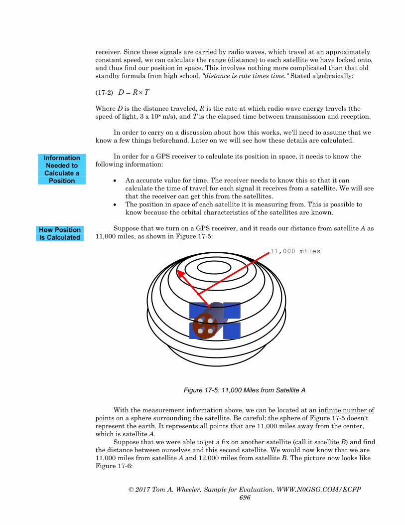
Suppose that we turn on a GPS receiver, and it reads our distance from satellite A as
11,000 miles, as shown in Figure 17-5:
11,000 miles
Figure 17-5: 11,000 Miles from Satellite A
With the measurement information above, we can be located at an infinite number of
points on a sphere surrounding the satellite. Be careful; the sphere of Figure 17-5 doesn't represent the earth. It represents all points that are 11,000 miles away from the center, which is satellite A.
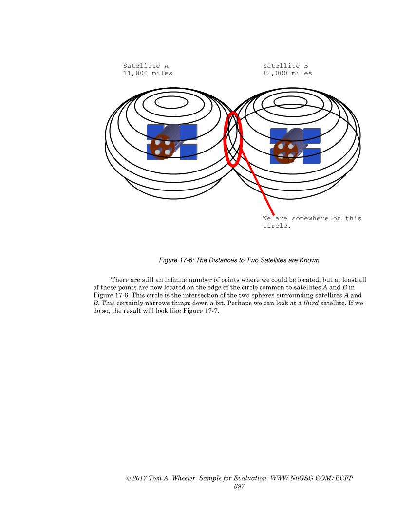
Suppose that we were able to get a fix on another satellite (call it satellite B) and find the distance between ourselves and this second satellite. We would now know that we are 11,000 miles from satellite A and 12,000 miles from satellite B. The picture now looks like Figure 17-6:
Information Needed to Calculate a
Position
How Position is Calculated
© 2017 Tom A. Wheeler. Sample for Evaluation. WWW.N0GSG.COM/ECFP 697
Satellite A 11,000 miles
Satellite B 12,000 miles
We are somewhere on this circle.
Figure 17-6: The Distances to Two Satellites are Known
There are still an infinite number of points where we could be located, but at least all
of these points are now located on the edge of the circle common to satellites A and B in Figure 17-6. This circle is the intersection of the two spheres surrounding satellites A and B. This certainly narrows things down a bit. Perhaps we can look at a third satellite. If we do so, the result will look like Figure 17-7.
© 2017 Tom A. Wheeler. Sample for Evaluation. WWW.N0GSG.COM/ECFP 698
Satellite A 11,000 miles
Satellite B 12,000 miles
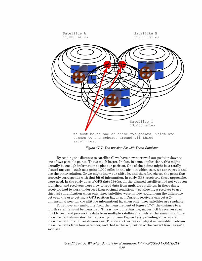
We must be at one of these two points, which are common to the spheres around all three satellites.
Satellite C 13,000 miles
Figure 17-7: The position Fix with Three Satellites
By reading the distance to satellite C, we have now narrowed our position down to
one of two possible points. That's much better. In fact, in some applications, this might actually be enough information to plot our position. One of the points might be a totally absurd answer -- such as a point 1,000 miles in the air -- in which case, we can reject it and use the other solution. Or we might know our altitude, and therefore choose the point that correctly corresponds with that bit of information. In early GPS receivers, these approaches were used. In the early days of GPS (late 1980s), all the planned satellites had not yet been launched, and receivers were slow to read data from multiple satellites. In those days, receivers had to work under less than optimal conditions -- so allowing a receiver to use this last simplification when only three satellites were in view could mean the difference between the user getting a GPS position fix, or not. Current receivers can get a 2-dimensional position (no altitude information) fix when only three satellites are readable.
To remove any ambiguity from the measurement of Figure 17-7, the distance to a fourth satellite must be measured. This is now quite feasible; modern GPS receivers can quickly read and process the data from multiple satellite channels at the same time. This measurement eliminates the incorrect point from Figure 17-7, providing an accurate measurement in all three dimensions. There's another reason why it is desirable to obtain measurements from four satellites, and that is the acquisition of the correct time, as we'll soon see.

© 2017 Tom A. Wheeler. Sample for Evaluation. WWW.N0GSG.COM/ECFP 699
A GPS receiver can give the end-user three important pieces of information. First, the user's position in three dimensions (altitude, longitude, and latitude) is reported by the calculation method above. Second, the time is available, as the receiver is able to receive the time information from the satellites themselves, which have extremely precise atomic clocks onboard. Finally, the speed or velocity of the receiver is available. The receiver calculates its speed by using equation 17-3 below. All the GPS receiver needs to do in order to calculate velocity is to take two successive distance measurements and divide them by the time interval between them:
(17-3) txv
∆∆
=
Where ∆x is the difference between two position readings, and ∆t is the difference
between the two points in time where these positions were measured. Accurate timing is essential to the operation of GPS, because radio waves travel at a
very high speed ( 3 x 10⁸ m/s, or 186,000 miles/sec ). A timing error of just 10 µs represents a distance measurement error of 3,000 meters (1.86 miles, or 9840 feet)!
Each of the satellites contains several atomic clocks. These are very accurate timekeeping devices that use the natural frequency of either cesium or rhubidium atoms to control their oscillator circuit (much like using a quartz crystal in a conventional oscillator). Because each satellite has several of these clocks on board, their timing errors can be mathematically cancelled to provide superb accuracy (and extra reliability, in case one of them happens to fail). In addition, the satellite clocks are periodically corrected by the master control station located at Falcon Air Force base, near Colorado Springs, Colorado.
Atomic clocks are very expensive; the satellite clocks cost over $50,000 apiece. If a receiver were required to have such a clock on board, only the very rich could afford to use GPS! However, by using a little algebra, and comparing the measurements from several satellites, a GPS receiver can correct its own internal clock to match that of the satellites. Figure 17-8 shows the effect of timing errors on position.
In the figure we have restricted the discussion to two dimensions, which makes it easier to draw the diagrams and understand the results. These results will also be valid in three dimensions. We have also shown distances in units of time, rather than distance. This makes it easier to see how the corrections can be applied (since we know that distance is obtained by multiplying time and velocity).
Our actual position is point X, which is one of the two points of intersection from the ranges derived from satellites A and B. Our receiver has reported that it took 50 ms for the signal to get to us from satellite A (a distance of 9300 miles), and 60 ms from satellite B (a distance of 11,160 miles). If all of our timing sources (both satellites and the receiver) agree, then this is the point that will be reported.
What Data are Presented by a GPS Receiver?
Getting Accurate Time

© 2017 Tom A. Wheeler. Sample for Evaluation. WWW.N0GSG.COM/ECFP 700
Our Actual Position
True Range A 50 mS
True Range B 60 mS
Satellite A Satellite B
Pseudo Range Reported Position with Error
10 mS Timing Error 10 mS Timing
Error
X
Figure 17-8: The Effect of Timing Errors
However, what happens if our receiver clock is 10 ms fast? It will report a larger
distance to each of the satellites, which is represented by the dashed circles. The receiver now thinks that it is 60 ms (11,160 miles) to satellite A, and 70 ms (13,020 miles) to satellite B. In other words, the 10 ms of clock error caused the range to each satellite to be off by 1,860 miles! These ranges containing timing errors are sometimes called pseudo-ranges, meaning that they are false range measurements. This problem can be resolved by taking a range measurement from a third satellite, as shown in Figure 17-9.

© 2017 Tom A. Wheeler. Sample for Evaluation. WWW.N0GSG.COM/ECFP 701
Receiver's time baseis adjusted until therange readings fromall three satellitesconverge at thispoint, which will bethe true position.
True Range A50 mS
True Range B60 mS
Satellite A Satellite B
10 mS TimingError10 mS Timing
Error
X
True Range C70 mS
Satellite C
Figure 17-9: Correcting the Time
If our receiver measures from a third satellite, it will find a similar timing error (10
ms) in the range measurement. A little geometry will also reveal that the receiver will "discover" that the three pseudo-range circles do not coincide at our actual position. The receiver then knows that its internal clock is off, and can then make an adjustment to correct itself.
This adjustment is not made by trial and error. Because four satellites are actually used in three dimensions, a system of four equations in four unknowns must be solved to determine the nature of the timing error. These calculations are carried out by the microprocessor in the GPS receiver and are of little consequence to the technician. Once the receiver has corrected its time clock, it can calculate its position with high accuracy.
GPS receivers use a precision crystal oscillator as their internal clock source, and constantly perform this correction as they receive data from the satellites. This is one reason that you can really trust the time given on the display of a GPS receiver, as long as the GPS unit has recently locked onto at least four satellites, and has been set for the correct time zone. The GPS system uses coordinated universal time (UTC) as its standard, not the regional time of any particular location.
In order to calculate position from the satellite timing signals, the positions of the
satellites must be known. Each satellite has a specific and precise orbit and orbital position that is predictable, and this information is programmed into a lookup table called an almanac that is contained within the software in the GPS receiver. The almanac of a GPS
Finding the Satellite
Positions

© 2017 Tom A. Wheeler. Sample for Evaluation. WWW.N0GSG.COM/ECFP 702
receiver contains the planned orbital patterns of all GPS satellites in the receiver's memory.
GPS satellites travel in orbits that are 12,200 miles above the earth's surface, and are designed to orbit the earth once every 12 hours. This is part of the GPS master plan, and it allows all the satellites to periodically pass over the Colorado Springs master control station for maintenance and updating.
At an altitude of 12,200 miles, a satellite must travel at an average speed of 8,500 mph in order to have a stable orbit. If the satellite moves too fast or slow, it will leave the intended orbit with disastrous results. Fortunately, at this height, there is no significant atmosphere to interfere with the motion of the satellite, and the primary forces acting on the satellite are the gravitation pulls of the earth, sun, and moon.
Each satellite has a specific identification code, and these codes are programmed into the receiver's almanac. Therefore, when a GPS receiver receives a message from a satellite, it can determine the satellite's position in space by looking up its ID code in the almanac, and then applying the almanac information into the satellite's orbital equations.
In spite of the extreme precision involved in planning the orbits of GPS satellites,
orbital changes do occur. Errors build up in the orbital position of a satellite, and are caused by the gravitation pulls of the sun and moon, and the changing effect of solar radiation.
Solar radiation tends to exert a push on satellites, but because the earth, sun, and the satellite are in an ever-changing arrangement, this extra push can cause very complicated changes in the orbit, especially when the earth passes between the satellite and the sun (where the solar push temporarily disappears).
Since a GPS satellite passes by one of the Department of Defense monitoring stations twice a day, its altitude, position, and speed can be accurately measured, and this information can be relayed back up to the satellite. The satellite then retransmits this data, called the ephemeris data, along with its timing message. The word "ephemeris" means short-lived -- the ephemeris data provide essentially short-term, fine-tuning adjustments to the orbital information in the GPS almanac.
The almanac in a receiver gives the planned orbital data for each GPS satellite, while the ephemeris provides the same information that has been "fine-tuned" by the master control station to reflect the actual orbital conditions of the satellite. By using the ephemeris data, GPS receivers always know the most up-to-date and exact orbital information for each satellite. This is important, for to calculate position accurately, the receiver must be able to calculate the position of each satellite with precision.
GPS has the potential to be useful to enemies of the United States, and because of
that, the Department of Defense has implemented selective availability, or SA. When selective availability is enabled, errors are deliberately introduced into the system. For example, random errors can be introduced into the ephemeris and timing messages on the C/A (civilian) channel, which directly degrades the accuracy of GPS measurements. Even with selective ability enabled, innovative GPS receiver manufacturers have found ways of coping with these errors, as we'll see in a later section.
Anti-spoofing or AS is an additional mode that can be selectively turned on or off by the government. The purpose of anti-spoofing is to prevent an enemy from transmitting false navigation codes on top of the authentic satellite data. When AS is enabled, the P code is further encrypted to form the Y code.
Ephemeris Information
Selective Availability
Anti-Spoofing

© 2017 Tom A. Wheeler. Sample for Evaluation. WWW.N0GSG.COM/ECFP 703
Section Checkpoint
17-9 What two pieces of information must a GPS receiver possess in order to find its position in space?
17-10 Explain how a position "fix" can be obtained from three and four satellites. 17-11 List the three types of information a GPS receiver can provide for the user. 17-12 What type of clocks are used in GPS satellites? Why are these practical for receivers? 17-13 Explain how a GPS receiver finds the correct time. 17-14 How does a GPS receiver know the exact position of each satellite? 17-15 What forces can move a satellite from its planned orbit? 17-15 Explain what the purpose of ephemeris data is. What is the difference between almanac
and ephemeris data? 17-16 What is selective availability? How is it implemented?
17-3 GPS Segments and Navigation Signal Processing
The GPS system contains an impressive array of technologies. Because of this, understanding how all the pieces of the system fit together can be a little intimidating at first. GPS can be best understood if it is analyzed in pieces or segments. The GPS system is divided into three parts. These are the space segment, the control segment, and the user segment.
The GPS satellites make up the space segment. The satellites transmit the navigation messages on two different phase-modulated frequencies (we will see why two frequencies are used later).
The control segment runs the entire GPS system. It consists of a master control station or MCS which is located at Falcon Air Force base near Colorado Springs, CO, and a number of monitoring stations distributed around the globe. The primary mission of the control segment is to track the position and health of all GPS satellites, and update the navigation messages transmitted by each satellite. Part of the navigation message includes the ephemeris data. The ephemeris is the set of recently-computed (and short-lived) information about the GPS satellite's orbit. The ephemeris data is transmitted periodically to each GPS satellites by the master control station, which has received data about each "bird" from the various tracking stations around the world. The satellite then retransmits this information along with the navigation message. In this way, all GPS receivers have exact and up-to-date information about the orbital position of each satellite, which compensates for errors that accumulate in the satellite orbits.
The user segment consists of all receivers in use on and near the earth. A GPS receiver has a tremendous computational task; it must lock onto at least four different satellites, and compute its position from the received timing signals. Most GPS end-users are intimately familiar with their own equipment (the receivers), but have no real idea of the complex network of resources that supports the receiver's operation.
The GPS satellites have been released in blocks (groups) since the system's inception in 1978. There are currently 29 active satellites in this segment, divided into blocks. Ten Block I satellites were launched between February 1978 and October 1985. These were used as a test bed to demonstrate the capabilities of the system, and all of them have long since been turned off, or have failed. The Block I satellites lacked SA capability, and could only provide 3-4 days of positioning service without ground station contact.
Nine Block II satellites are in existence, and eight of them are still operational. These are an improvement over the Block I units, and have enough memory for 14 days of unsupervised operation. Their design life span is about 7.5 years, and their weight is 1860 pounds when inserted into orbit. These satellites were launched between 1989 and 1990.
Space Segment

© 2017 Tom A. Wheeler. Sample for Evaluation. WWW.N0GSG.COM/ECFP 704
The Block IIA satellites were launched between 1990 and 1994, and have expanded memory capabilities. They can provide 180 days of service without contact with the control segment, with some degradation of positional accuracy over time. There are 18 functional Block IIA satellites in orbit.
The Block IIR satellites are designed as replacements for the aging fleet of Block II and Block IIA units; the first of these was unsuccessfully launched in 1997. These satellites are further refined in that they can operate at least 14 days without contact from the control segment, and up to 180 days when operating in the autonomous navigation (AUTONAV) mode. Full accuracy is maintained without control segment contact by using inter-satellite ranging and communication. The data obtained automatically updates the navigation message from each satellite. Each Block IIR satellite is designed to live for 7.8 years.
Figure 17-10 shows the status of the Block II GPS satellites as of the time of this writing.
Launch Order Service Vehicle Number (SVN)
Launch Date Orbital Plane
USSC Object Number
II-2 13 10 JUN 1989 B3 20061 II-5 17 11 DEC 1989 D3 20361 II-9 15 01 OCT 1990 D2 20830 IIA-10 23 26 NOV 1990 E4 20959 IIA-11 24 04 JUL 1991 D1 21552 IIA-12 25 23 FEB 1992 A2 21890 IIA-14 26 07 JUL 1992 F2 22014 IIA-15 27 09 SEP 1992 A3 22108 IIA-16 32 22 NOV 1992 F1 22231 IIA-17 29 18 DEC 1992 F4 22275 IIA-19 31 30 MAR 1993 C3 22581 IIA-20 37 13 MAY 1993 C4 22657 IIA-21 39 26 JUN 1993 A1 22700 IIA-22 35 30 AUG 1993 B4 22779 IIA-23 34 26 OCT 1993 D4 22877 IIA-24 36 10 MAR 1994 C1 23027 IIA-25 33 28 MAR 1996 C2 23833 IIA-26 40 16 JUL 1996 E3 23953 IIA-27 30 12 SEP 1996 B2 24320 IIA-28 38 06 NOV 1997 A5 25030 IIR-2 43 23 JUL 1997 F5 24876 IIR-3 46 07 OCT 1999 D2 25933 IIR-4 51 11 MAY 2000 E1 26360 IIR-5 44 16 JUL 2000 B3 26407 IIR-6 41 10 NOV 2000 F1 26605 IIR-7 54 30 JAN 2001 E4 26690 IIR-8 56 29 JAN 2003 B1 27663 IIR-9 45 31 MAR 2003 D3 27704 IIR-10 47 21 DEC 2003 E2 -
Figure 17-10: GPS Block II/IIA/IIR Satellite Status
The satellites repeatedly transmit a navigation message that is sent at a data rate of
50 BPS. The complete navigation message consists of 25 frames (data blocks), each containing 1500 bits. Each frame is divided into five 300-bit subframes, which are 10 words of 30 bits each. At the 50 bps data rate, it takes 6 seconds to send a subframe, 30 seconds
Navigation Messages

© 2017 Tom A. Wheeler. Sample for Evaluation. WWW.N0GSG.COM/ECFP 705
for a frame, and 12.5 minutes for the entire navigation message. Figure 17-11 shows the basic structure of the navigation message frames.
Figure 17-11: Navigation Message Frame Structure
Each subframe starts with the telemetry word, and handover word (HOW). The
handover word gives critical timing information for extracting the P code. When the HOW is multiplied by 4, it gives the current position called x1 for the next subframe within the P code. The P code doesn't repeat for 266.4 days, so receivers need extra help in locking onto it (otherwise it might take a receiver years to lock onto the P code!) Of course, the receiver must be programmed with the P code in order to use the handover word. In this respect, you can see that the C/A code must first be acquired before the P code can be locked onto by a receiver.
Notice that subframes 1,2, and 3 contain timely information. These contain the clock correction factor and satellite ephemeris (recently updated orbital data) that are needed for a receiver to accurately calculate position. These are transmitted with every complete frame (30-second transmission), so their information is available every 30 seconds.
Subframes 4 and 5 are less time-critical. They are used to build a long message string containing the general telemetry data and timebase information, as well as the satellite almanac and health status. 25 complete sets of subframes 4 and 5 are needed to construct these messages completely. Therefore, it takes (25)(30) seconds (12.5 minutes) to send the entire "page" of information transmitted in subframes 4 and 5.
You can think of the contents of subframes 4 and 5 as individual paragraphs that are used to construct two different document "pages," one of which will contain a complete message about the UTC time and almanac (orbital data) for satellites with a service vehicle number 25 or greater. The other "page" which will contain the almanac data for satellites with SVNs 1 through 24 and internal housekeeping information (such as the operational "health" status of the various satellite subsystems.) It always takes 25 complete paragraphs to build these two document pages. Note that with the almanac information from any one satellite, the receiver can get a rough indication of the position for any other satellite in the array. This is very useful, as it allows the receiver's internal almanac data
Telemetry Word HOW
0 30 60
Clock Correction Data
300 Bit Number
Telemetry Word HOW Ephemeris Data
Telemetry Word HOW Ephemeris Data
Telemetry Word HOW Almanac, UTC, Nav Message
Telemetry Word HOW Housekeeping / Almanac
Subframe 1
Subframe 2
Subframe 3
Subframe 4
Subframe 5
These are repeated every 30 seconds
1/25th of the two "document"
pages