chapter 13 ventilation - food and agriculture …chapter 13 – ventilation 331 from the...
TRANSCRIPT
329
Chapter 13
Ventilation
IntroductIon The quality of the environment in agricultural buildings is governed by such factors as temperature, light, moisture, air quality and movement, dust, odours and disease agents. The environment affects animal comfort and health – and ultimately production. It also influences the quality and longevity of stored products. From an engineering standpoint, the environment can be closely controlled. However, economic factors often limit the extent to which control can be justified.
The particular region of the country and the associated climatic zone will influence the manner in which environmental requirements are met. A humid area may require homes with open construction to provide continual ventilation for comfort, whereas an arid region may need buildings of great thermal capacity to protect against daytime heat and night-time chill.
As a general rule, tropical climates are found within the tropics. However, the influence of the climate on structures makes the techniques used applicable to many regions outside the tropics, e.g. the Middle East.
The following brief discussion of Africa’s climatic zones is general and such zones can be found worldwide in the tropics. It illustrates the wide variety of situations with which engineers are faced when designing environmentally suitable buildings for people, animals and products.
clImatIc zonesThere are several climatic zones on the African continent, with widely varying characteristics.
1. Low-latitude, wet equatorial: high rainfall and humid, with a mean temperature close to 27 °C throughout the year. (Congo Basin).
2. Monsoon and trade wind littoral: climate dominated by trade winds. Maximum rain in high-sun season; minimum rain following low-sun season. Intense showers in eastern coastal zone. Warm throughout the year. (Central and western Africa and east coast).
3. Wet–dry tropical: typified by very wet high-sun season and a very dry low-sun season, (West and southern Africa).
4. Dry tropical: characterized by extreme heat in the high-sun season and cool in low-sun periods. Gradually changes from arid to semi-arid and into wet–dry tropical zone. (Sahara, South Africa).
5. Dry subtropical: a north–south extension of the dry tropical zone. Greater annual temperature range. (North and south Africa).
6. Altitude-modified wet–dry tropical: increases in altitude generally result in an increase in precipitation and a reduction in mean temperatures. Precipitation is seasonal and varies from 500 to 1 500 mm, depending on local conditions. (Inland east and southeast Africa).
Climate can also vary greatly over relatively small areas, in particular where the country is hilly.
For design purposes, local climatic data from a nearby meteorological station should be obtained if possible.
VentIlatIon processVentilation is one of several methods used to control the environment in farm buildings where it fulfils two main functions: controlling the temperature and controlling the moisture within a building. Ventilation may also be necessary to maintain adequate levels of oxygen and to remove generated gases, dust, odours and pathogens.
There is a considerable range of ventilation requirements that depend on the local climatic conditions and the specific enterprise being served. This is illustrated by the following examples:
1. A cattle shelter in a tropical climate requires little more than shade from a roof with the structure located to obtain maximum breeze.
2. A cattle shelter in a cold climate (seasonal frost) may be open on the sunny side and provided with ventilation openings at the ridge and along the rear eaves. The temperature will be cold but condensation will be controlled.
3. A poultry house (with cages) in a cold climate, if heavily insulated, can be kept comfortably warm while mechanical ventilation removes excess moisture and odours.
4. Potatoes that are stored in either a mild or a cold climate may be cooled by ventilation alone. Continual air movement is required to maintain a uniform environment. The amount of insulation used will be dictated by the lowest temperature expected.
A great deal of research has been carried out to determine the ideal environmental conditions for

330 Rural structures in the tropics: design and development
various classes of livestock, types of plant and animal products. Within economic constraints, the better these ideal conditions can be maintained, the more successful the enterprise will be. Meat animals will gain weight faster and more efficiently, dairy cattle will produce more milk, and stored produce will maintain better quality and suffer fewer losses.
determination of ventilation ratesThe objective of designing a ventilation system is to determine the ventilation rate to maintain an acceptable temperature, as well as acceptable moisture and contaminant levels, inside a building. To determine the ventilation rates, heat and moisture balance calculations have to be performed on a building envelope. Chapter 10 [Table 10.2] presents the heat and moisture production rates of some selected animals. The sensible heat balance is used to determine the maximum ventilation rate for summer conditions, while the moisture balance is used to determine the minimum ventilation rate for winter conditions. The following examples illustrate these methods.
Heat balance for determinationof maximum ventilation rateFigure 13.1 below illustrates sensible heat balance in an animal house.
Figure 13.1 sensible heat balance in a typical animal house
The steady-state heat balance in Figure 13.1 requires heat gains to equal heat losses. These are illustrated below. The heat gains are:
• sensible heat from animals (qs)• sensible heat from motors and lights (qm)• sensible heat from the sun (qso)• sensible heat from heaters (qh)• sensible heat from the ventilation system (qvi)
The heat losses are:• sensible heat loss through the ventilation system
(qvo)• sensible heat loss through the building shell (qw)• sensible heat loss through the floor (qf)• sensible heat loss used to evaporate moisture (qe)
qw
qvoqf
fan
qw
qmqhqviinlet
vapour
heater
lights motor
water
qsoqs
qe
The sensible heat loss used to evaporate moisture (qe) is normally included in the qs term and thus not expressed explicitly.
The overall steady-state equation is:
where:U = overall unit area thermal conductance of component (W/m2K). Table 12.1 shows U values for some selected structural componentsA = area of structural component (m2)c = path of heat transfer, which may be a wall or roof component P = building perimeter (m) F = an experimentally determined perimeter heat loss factor (W/mK). The values of F for an un-insulated and unheated slab floor on grade range between 1.4 and 1.6 W/mK, depending on how low the ambient temperature is Cp = specific heat of moist air (J/kgK) r = air density (kg/m3) V = the volumetric airflow rate (m3/s) ti and to = indoor and outdoor temperatures (°C).
The above equation is used to determine: (i) the required ventilation rate to maintain a given inside temperature for a given heater capacity; (ii) the minimum outside temperature (balance temperature) to maintain the desired inside temperature without using supplemental heat (qh = 0) at a given ventilation rate; and (iii) the size of heater required to maintain the desired inside temperature for a given ventilation rate and outside (design) temperature.
ExampleDetermine the ventilation rate for a laying-hen house with 30 000 hens having an average body mass of 1.40 kg. The inside temperature is to be maintained at 18 °C, with relative humidity of 60 percent. Assumptions: no supplemental heating; no solar heat; no heat from motors; the ∑AU and FP factors are 1 001 and 272 W/°C, respectively. The outside temperature is 0 °C.
SolutionUsing the above equation, the unknowns are qs and r.
Find qs:
From Table 10.2, the sensible heat production per bird is 3.9 W/kg.
Therefore,
qs = 3.9 W/kg × 1.40 kg/bird × 30 000 birds/house = 163 800 W/house.
c
to)(tiVCpFP(AU)cqhqsoqmqs −
⋅⋅++=+++ ∑ ρ

331Chapter 13 – Ventilation
From the psychrometric chart, with a dry-bulb temperature of 18 °C and 60 percent relative humidity, the specific volume is 0.826 m3/kg. The density is the inverse of specific volume, so the density is 1.21 kg/m3.
Hence, ( )( )
( )01821.110060182721001163800
−⋅⋅−+−
=V
= 6.4 m3/s-house
moisture balance for determination of minimum ventilation rateFigure 13.2 below illustrates moisture balance in an animal house.
Figure 13.2 moisture balance in a typical animal house
The steady-state moisture balance in Figure 13.2 requires that:
mvo = mvi + mp
where:mvo = the rate at which moisture is carried out of the airspace by ventilation air (kg/s)mvi = the rate at which moisture is carried into the airspace by ventilation air (kg/s)mp = the rate at which moisture is produced within the airspace (kg/s).
After a few steps, the above equation can be rewritten as:
where:ma = mass flow rate of moisture (kg/s)r = density (kg/m3)V = volumetric flow rate (m3/s)mp = moisture production of the animals (kg/s)Wi and Wo = humidity ratio of inside and outside air conditions (kgw/kg da).
ExampleA total of 70 dairy cows at 500 kg body mass are housed in a mechanically ventilated building. What must be the ventilation rate in order to maintain 70 percent relative
mpmvi
water
mvowatervapour
−
=⋅=WoWi
mpVmaρ
humidity at 20 °C if the outside temperature is 5 °C, with 90 percent relative humidity?
SolutionFrom the psychrometric chart, at 5 °C and 90 percent relative humidity, Wo = 0.0049 kgw/kg da. At 20 °C and 70 percent relative humidity, Wi = 0.0102 kgw/kg da.
From Table 10.2, the moisture production data are shown at 12 °C (445 g/h-animal) and 25 °C (910 g/h-animal). Since we need the moisture to be produced at 20 °C, we interpolate to obtain the moisture production. This yields 731 g/h-animal.
The moisture content may also be expressed as:
Therefore:
Total moisture produced = 0.000203 kg water/s-cow× 70 cows/house = 0.014214 kg water/s-house
Then:
For inlet conditions, ri = 1.27 kg/m3
Hence,
gkg
sh
h-cow=⋅⋅ 000203 kg water/s-cow.0
10001
36001731 g water
Ma (0.0102 − 0.0049) kgw/kg da0.014214 kgw/s ⋅ house
= = 2.68 kg da/s-house
MaVi ρi
= = = 2.11 m3/s27.168.2
MaVi ρi
= = = 2.23 m3/s20.168.2
For outlet conditions, ro = 1.20 kg/m3
Hence,
gkg
sh
h-cow=⋅⋅ 000203 kg water/s-cow.0
10001
36001731 g water
Ma (0.0102 − 0.0049) kgw/kg da0.014214 kgw/s ⋅ house
= = 2.68 kg da/s-house
MaVi ρi
= = = 2.11 m3/s27.168.2
MaVi ρi
= = = 2.23 m3/s20.168.2
Figure 13.3 shows an example of a ventilation curve for both temperature and moisture control. In summer, the main objective of ventilation is temperature control, while in winter the main objective is moisture control.
Figure 13.3 a sample ventilation curve for both temperature and moisture control
gkg
sh
h-cow=⋅⋅ 000203 kg water/s-cow.0
10001
36001731 g water
Ma (0.0102 − 0.0049) kgw/kg da0.014214 kgw/s ⋅ house
= = 2.68 kg da/s-house
MaVi ρi
= = = 2.11 m3/s27.168.2
MaVi ρi
= = = 2.23 m3/s20.168.2
gkg
sh
h-cow=⋅⋅ 000203 kg water/s-cow.0
10001
36001731 g water
Ma (0.0102 − 0.0049) kgw/kg da0.014214 kgw/s ⋅ house
= = 2.68 kg da/s-house
MaVi ρi
= = = 2.11 m3/s27.168.2
MaVi ρi
= = = 2.23 m3/s20.168.2
-30 -25 -20 -15 -10
Outside temperature °C
Ventilation forhumidity control
Ventilation fortemperature control
Ven
tila
tio
n r
ate
-5 5 10 30 3520 2515-0

332 Rural structures in the tropics: design and development
natural ventilation
Thermal convection or stack effectNatural ventilation is provided from two sources: thermal convection and wind. Air that is hotter than the surrounding air is less dense and experiences an upthrust caused by thermal buoyancy.
Whenever a building contains livestock, the production of sensible metabolic energy is always available to warm the air entering from the outside. Similarly, air may be heated in a greenhouse by incoming radiation. Provided there are two apertures with a height differential, convection currents will force the heated, less dense air out of the upper aperture to be replaced by an equal volume of cooler, denser air from outside. This is referred to as the ‘stack effect’.
Natural ventilation caused by the stack effect can provide the minimum ventilation requirement under winter conditions. While this system may be less
expensive than a mechanical system, it will also be less positive in its ventilation action and more difficult to control.
A building that is open on one side may be ventilated naturally by leaving the ridge open for an outlet and a slot along the rear for an inlet. An enclosed building may be more positively ventilated with stack outlets and correctly sized inlets.
Determination of air inlet and outlet sizesTo determine the inlet and outlet areas required to provide a given ventilation rate by thermal convection, the following equation, based on stack effect theory, can be used:
( )2
211V 2WVSTi
HphgAi
2Ao+⋅⋅
⋅⋅==
ρ
Figure 13.4a natural ventilation stack design (dryer)
CB
A
1
8
X 1
0-3
AR
EA O
F A
i AN
D A
o O
PEN
ING
S m
2
X 1
0-2X
10-1
X 10-1X 10-2X 10-3
6
5
4
3
2
1
8
6
5
4
3
2
1
8
6
5
4
3
2
11 2 3 4 5 6 8 1 2 3 4 5 6 8 1 2 3 4 5 6 8 1
VENTILATION RATE m3/s
333Chapter 13 – Ventilation
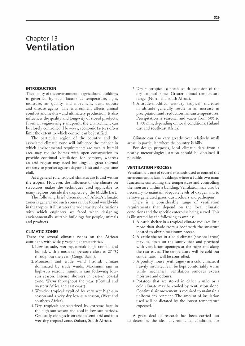
where:Ai = inlet (m²)Ao = outlet area (m²)g = acceleration due to gravity (9.76 m/s2)h = height difference, inlet to outlet (m)Hp = heat supplied to building (W)Ti = absolute temperature in building (K, K = (°C + 273))r = density of air in building (kg/m³), 1.175 at 25 °CS = specific heat of air (1 005 J/kg °C)V = ventilation rate (m³/s)W = heat loss through building shell (W/°C).
The values in Figure 13.4a and Figure 13.4b were developed using this equation. The values in (a) are for a solar-flue dryer, while those in (b) fit the conditions in a building more closely.
Natural ventilating systems may be non-adjustable, manually adjustable, or automatically controlled. As natural systems are likely to be chosen for economy
reasons where conditions are not severe, manual adjustment should be the method of choice in most cases.
Wind ventilationAs the wind flows around a building, gusts and lulls create regions where the static pressure is above or below the atmospheric pressure in the free air stream. In general, these pressures are positive on the windward side, resulting in an inflow of air, and negative on the leeward side, resulting in an outflow of air. Pressures are generally negative over low-pitched roofs. Figure 13.5 shows natural ventilation in a gable-roof building primarily as a result of wind blowing over the ridge.
Factors to consider in the design of a naturally ventilated structure The following factors should be considered in the design of a naturally ventilated structure:
Figure 13.4b natural ventilation stack design (barn)
C D
BA
1
8
X 1
0-0
AR
EA O
F A
i + A
o O
PEN
ING
S m
2
X 1
0-1X
10-2
X 10-0X 10-1X 10-2
6
5
4
3
2
1
8
6
5
4
3
2
1
8
6
5
4
3
2
11 2 3 4 5 6 8 1 2 3 4 5 6 8 1 2 3 4 5 6 8 1
VENTILATION RATE m3/s

334 Rural structures in the tropics: design and development
Figure 13.5 natural wind ventilation over a gable-roof building
Location of the structure: The structure should be located so that the ridge of the building is perpendicular to the prevailing summer winds. When structures are set side by side, the following equation may be useful in determining the separation distance:
where: DSD = separation distance (metres)H = total height of the obstruction (metres)L = the length of the obstruction (metres).
Insulation: The walls and ceilings should be insulated in order to reduce excessive heat transmission into and out of the building.
Ceiling slope: The ceiling slope depends on the configuration of the building. If no ceiling is used, the lower side of the roof should slope between 1:3 and 1:2 to allow air to move up toward the ridge at an adequate rate.
Ventilation openings: The size of the ventilation openings is critical to ensure proper ventilation rates.
Ways of controlling natural ventilationNatural ventilation is difficult to control. However, manipulation of the following parts of the structure may help.
Gentle upward movement
Winter ventilation - no wind outside
slow overturnof air
Winter ventilation - wind blowing
Sun heat Ridge vent removeshot air near roof
Summer ventilator - sidewall doors open
LHDSD ××= 4.0
Building width: The wider buildings become, the more difficult it becomes to distribute fresh air to all parts of the building. The widest buildings may be found in areas with higher average wind speeds and may not exceed about 14 metres. Wider buildings will require mechanical ventilation assistance.
Sidewall openings: Openings along the length of the building provide a means for fresh air to enter. Moveable curtains are used for controlling the opening size to accommodate various wind speeds and outside temperatures. Insulated curtains reduce conductive heat loss and the infiltration of cold air during winter periods.
Ridge openings: The purpose of the ridge-vent system (Figure 13.6) is to generate fresh-air ventilation during cold winter periods, thereby removing stale, moist air from the building. When the wind flows perpendicular to the ridge, it produces suction at the ridge which, when combined with thermal buoyancy, provides the force to extract air from the building. Upstands (Figure 13.7) of 15–30 cm above the ridge increase suction at the ridge and thus increase the ventilation rate. A baffle control can then be used to decrease ventilation if the need arises.
Figure 13.6 the ridge-vent system with adjustable louvers
Figure 13.7 ridge ventilator with upstands to prevent rain and increase suction
mecHanIcal VentIlatIonCompared with natural ventilation, mechanical ventilation using fans is more positive in its action, less affected by wind, and more easily controlled.
Louvers
Upstand
335Chapter 13 – Ventilation
Initial installation usually costs more and there is the added cost of operation. However, in many cases the advantages of mechanical ventilation outweigh the added expense.
Exhaust versus pressure systemsThere are two main types of mechanical ventilating system: pressure and exhaust. In a pressure system, the fan blows air through inlet openings into the building, creating a positive indoor pressure that pushes air out of the building through the outlet openings. In exhaust ventilation, the fan expels air from the building, creating a lower-than-atmospheric pressure inside the building. It is the pressure difference between outside and inside that causes the ventilation air to flow in through the inlets. For good control of the airflow, it is important for the building to be tightly sealed.
The exhaust ventilation system is popular because it is easier to control the distribution of the incoming air, and is generally less expensive, as well as being less complex than a pressure system. However, there are situations when the pressure system (one that forces air into the building) performs better. These include:
• very dusty conditions that tend to load up the fans• buildings with excessively loose construction
(many cracks)• when continuous recirculation is required.
Under some circumstances, pressure systems may cause humid air to be forced into building walls and ceilings. This can result in condensation and damage to wood and other materials.
A mechanical ventilation system comprises three main components: fans, air-distribution system and controls to regulate the fans.
Fans and blowersA fan is a mechanical device that uses energy inputs to move air, and can be described as the ‘heart’ of a mechanical ventilation system.
The two general types of fan are axial-flow and centrifugal. Axial-flow fans are normally divided into propeller and tube-axial types. They move air parallel to the shaft and are the most widely used types. Centrifugal (radial flow) fans (blowers) discharge air at right angles to the shaft and often operate at substantial pressures.
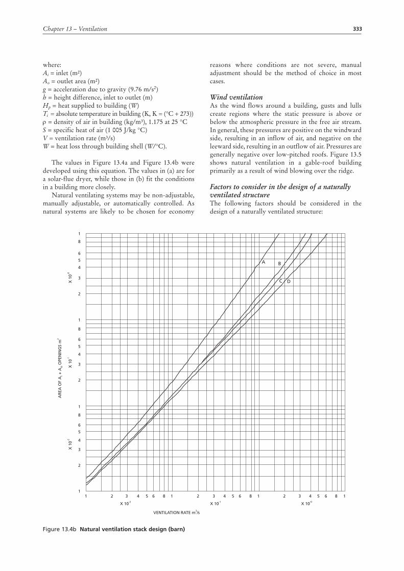
Propeller fans are the least expensive and the easiest to install. A propeller fan may have two to six (or more) blades. In general, the more blades a fan has, the greater the pressure the fan will develop. The best propeller fans have a close-fitting, curved inlet shroud or inlet ring, which improves the efficiency of the fan. Propeller fans are best suited to moving large volumes of air at pressures in the range of 30–50 Pa (3–5 mm of water), and they are the most commonly used in conventional farm building ventilation (Figure 13.8).
Figure 13.8 a propeller fan
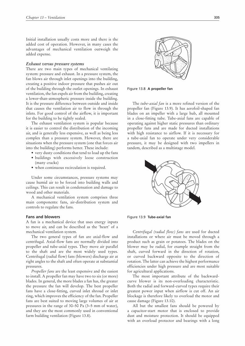
The tube-axial fan is a more refined version of the propeller fan (Figure 13.9). It has aerofoil-shaped fan blades on an impeller with a large hub, all mounted in a close-fitting tube. Tube-axial fans are capable of operating against higher static pressures than ordinary propeller fans and are made for ducted installations with high resistance to airflow. If it is necessary for a tube-axial fan to operate under very considerable pressure, it may be designed with two impellers in tandem, described as a multistage model.
Figure 13.9 tube-axial fan
Centrifugal (radial flow) fans are used for ducted installations or where air must be moved through a product such as grain or potatoes. The blades on the blower may be radial, for example straight from the shaft, curved forward in the direction of rotation, or curved backward opposite to the direction of rotation. The latter can achieve the highest performance efficiencies under high pressure and are most suitable for agricultural applications.
The most important attribute of the backward-curve blower is its non-overloading characteristic. Both the radial and forward-curved types require their greatest power input when airflow is cut off. An air blockage is therefore likely to overload the motor and cause damage (Figure 13.10).
All but the smallest fans should be powered by a capacitor-start motor that is enclosed to provide dust and moisture protection. It should be equipped with an overload protector and bearings with a long
336 Rural structures in the tropics: design and development
lubrication life. The fan should be enclosed with a wire safety guard. Shutters and hoods are necessary in cold climates but should not be needed in mild climates.
The type of fan selected is largely related to operating pressure. It is important to choose a fan with high performance efficiency in the required range of operating pressures in order to avoid unnecessarily high energy consumption.
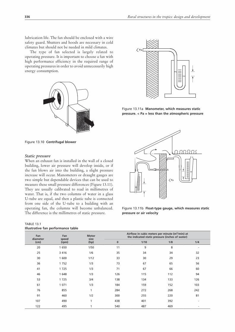
Figure 13.10 centrifugal blower
Static pressureWhen an exhaust fan is installed in the wall of a closed building, lower air pressure will develop inside, or if the fan blows air into the building, a slight pressure increase will occur. Manometers or draught gauges are two simple but dependable devices that can be used to measure these small pressure differences (Figure 13.11). They are usually calibrated to read in millimetres of water. That is, if the two columns of water in a glass U-tube are equal, and then a plastic tube is connected from one side of the U-tube to a building with an operating fan, the columns will become unbalanced. The difference is the millimetres of static pressure.
Figure 13.11a manometer, which measures static pressure. < pa = less than the atmospheric pressure
Figure 13.11b Float-type gauge, which measures static pressure or air velocity
Pa
o
o
Pa
Table 13.1Illustrative fan performance table
Fan diameter
(cm)
Fan speed (rpm)
motor size (hp)
airflow in cubic meters per minute (m3/min) atthe indicated static pressure (inches of water)
0 1/10 1/8 1/4
20 1 650 1/50 11 9 8 -
25 3 416 1/6 35 34 34 32
30 1 600 1/12 33 30 29 23
36 1 752 1/3 73 67 65 56
41 1 725 1/3 71 67 66 60
46 1 648 1/3 126 115 112 94
53 1 725 3/4 138 134 133 126
61 1 071 1/3 184 159 152 103
76 855 1 284 272 268 242
91 460 1/2 300 255 220 81
107 490 1 438 401 392 -
122 495 1 540 487 469 -

337Chapter 13 – Ventilation
Fan performance and selectionFan performance is expressed as the volume of air moved in cubic metres per second (m³/s), or pressure or resistance to airflow in Pa or millimetres of water static pressure (mm WG). Fan performance tables and/or curves are available from the manufacturers. These tables illustrate the maximum or cut-off pressure, efficiency and sound levels at different rotation velocities (rpm) and blade-angle settings, as well as the power requirements for various operating conditions. An illustration of fan performance data is given in Table 13.1.
Fan efficiency and efficiency ratiosFan efficiency is measured as the amount of air moved by the fan motor per unit of electrical energy input. Factors that influence the energy efficiency of a fan are motor efficiency, speed, blade design, blade-to-housing clearance and fan housing design.
Fan lawsWhen fan blades are mounted directly onto the motor shaft, it is assumed that the manufacturer has correctly matched the combination. However, some fans are belt-driven, allowing for a motor with a different speed, or pulleys of different sizes, to be substituted while the fan is in operation. Knowledge of the following basic fan laws can reduce problems:
• The delivery volume of a fan varies directly with its speed.
• The cut-off pressure of a fan varies directly as the square of its speed.
• The power requirement of a fan varies directly as the cube of its speed.
For example, assume a fan is belt-driven by a 300 W output and 1 725 rpm motor. If that motor is replaced by a 300W/3 400 rpm motor without changing pulleys, the following would occur: the volume discharged would be doubled, the cut-off pressure would be quadrupled and the horsepower requirement would be increased eightfold. The result would be such a badly overloaded motor that it would burn out unless the overload protector stopped the motor before any damage was done.
The mild climate of east and southeast Africa greatly simplifies the housing requirements for most animals and some plant products. However, it seems worthwhile to discuss several ventilation factors that apply primarily to cooler climates.
VentIlatIon system desIgn: cool clImates Fan location: Assuming an enclosed building, one to three fans can be located at ceiling level midpoint on the protected side (opposite the prevailing wind) of the building. A greater number of fans may be distributed along the protected side. The high level on the wall is desirable for summer heat removal and has little effect on the efficiency of moisture removal in cold weather.
Efficiency, in this case, means the amount of moisture removed per unit of heat used or lost. If outlet ducts are required, they should be insulated to an R of 0.5 to prevent condensation.
air distributionIn addition to the ventilation rate, it is necessary to consider the distribution of incoming air throughout the building. This is particularly important in both livestock-production buildings and product stores.
When considering fresh-air distribution, two distinct temperature situations are involved. In areas with winter frost, the outside air is cooler than the air inside the buildings, and fresh air must be delivered away from the stock to avoid cold draughts. However, in summer the animals may be subject to heat stress and may suffer considerably unless cooling air currents are directed to remove excess heat from their vicinity. A good air-distribution system also ensures that the animals receive an adequate supply of oxygen and that noxious gases are removed.
Air inletsVentilation is accomplished in an exhaust-type mechanical system by reducing the pressure within the building to below outside pressure, causing fresh air to enter wherever openings exist. The principal factors affecting the airflow pattern in a building are the speed and direction of the incoming fresh air. The size, location and configuration of the air inlets are therefore important factors when designing the distribution system.
The flow of air that streams through openings has been closely investigated and the results are summarized by the following statements:
• The speed at which the air stream travels is directly affected by its initial speed through the inlet.
• The distance the air stream travels is proportional to the initial speed at the inlet.
• The higher the initial speed of air entering the building, the greater the mixing of incoming air with the existing air.
• The higher the speed of cool air entering the building, the less it will sink.
It can be deduced from these findings that, in winter, openings should be small enough to provide sufficiently high velocities to avoid cold air falling directly onto the stock, to provide good air mixing, and to maintain the required airflow pattern at the low winter ventilation rate.
Velocities of around 3.5 to 5 m/s usually satisfy these requirements. However, at these velocities it is important to consider the effect of internal partitions, structural members and other obstructions to the flow, and it is also important for the building to be relatively airtight.
When air flows through an opening of any shape, the cross-section area of the issuing jet is reduced to
338 Rural structures in the tropics: design and development
60–80 percent of the total free area of the opening. A reasonable design value is 70 percent. This phenomenon, the vena contracta effect, increases the velocity of air emerging from the opening. The total area of air inlet must be proportional to total fan capacity. According to a common rule of thumb, the size of air inlets should be 0.4 m² of area for each m³/s of fan capacity (Table 13.2).
Table 13.2Ventilation inlet data (vena contracta = 0.7)
static pressure (mm H2o)
Velocity (m/s)
Inlet area (m² per m³/s)
5 2.9 0.493
10 4.1 0.348
15 5.0 0.286
20 5.8 0.246
25 6.5 0.219
32 7.3 0.196
The pressure drop across the inlet affects fan performance and therefore should be no higher than necessary. A draught gauge may be used to check the pressure difference across the inlet (between the inside and outside of the building at the inlet). A pressure difference of 10–20 Pa indicates a velocity of 4–6 m/s. Inlet openings, regardless of type, must be adjustable so that the correct air velocity can be maintained throughout the year.
Compared with inlets, the fan outlets have a minor role to play in the distribution of fresh air in a livestock building. The effect of an outlet is to cause a general slow drift of air towards the outlet position. This drift is easily overcome by convection, animal movements or the pattern of air movement established by the inlets. Only near the fan (within approximately 1 metre) can a positive air movement be detected. This applies to outlets in both exhaust and pressurized systems of ventilation. However, it is recommended that no inlet be placed closer than 3 metres to a fan.
Wind has a major effect on ventilation systems because it causes pressure gradients around buildings and directly impinges on components of the system. The pressure gradients will cause problems of uneven air entry, with more air entering on the windward side than on the leeward side of the building. Wind blowing against a fan reduces output and hoods do little to alleviate the problem. Wind blowing across a ridge chimney outlet may cause overventilation.
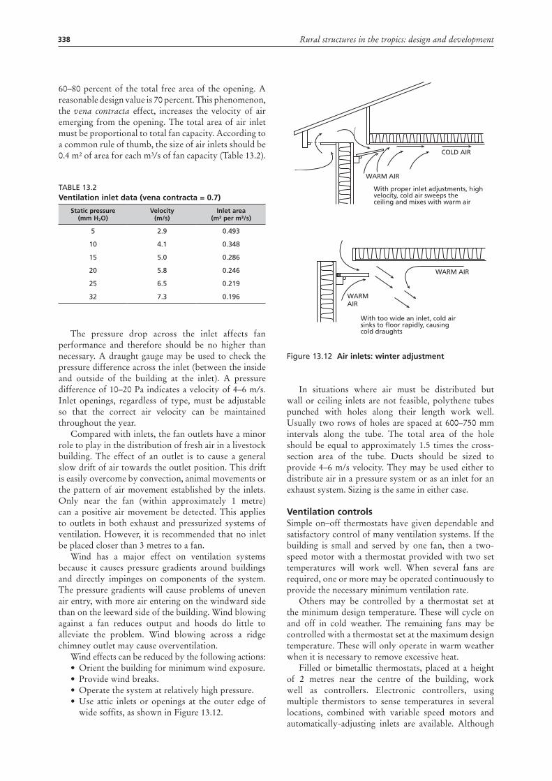
Wind effects can be reduced by the following actions: • Orient the building for minimum wind exposure.• Provide wind breaks.• Operate the system at relatively high pressure.• Use attic inlets or openings at the outer edge of
wide soffits, as shown in Figure 13.12.
Figure 13.12 air inlets: winter adjustment
In situations where air must be distributed but wall or ceiling inlets are not feasible, polythene tubes punched with holes along their length work well. Usually two rows of holes are spaced at 600–750 mm intervals along the tube. The total area of the hole should be equal to approximately 1.5 times the cross-section area of the tube. Ducts should be sized to provide 4–6 m/s velocity. They may be used either to distribute air in a pressure system or as an inlet for an exhaust system. Sizing is the same in either case.
Ventilation controlsSimple on–off thermostats have given dependable and satisfactory control of many ventilation systems. If the building is small and served by one fan, then a two-speed motor with a thermostat provided with two set temperatures will work well. When several fans are required, one or more may be operated continuously to provide the necessary minimum ventilation rate.
Others may be controlled by a thermostat set at the minimum design temperature. These will cycle on and off in cold weather. The remaining fans may be controlled with a thermostat set at the maximum design temperature. These will only operate in warm weather when it is necessary to remove excessive heat.
Filled or bimetallic thermostats, placed at a height of 2 metres near the centre of the building, work well as controllers. Electronic controllers, using multiple thermistors to sense temperatures in several locations, combined with variable speed motors and automatically-adjusting inlets are available. Although
COLD AIR
WARM AIR
WARMAIR
WARM AIR
With proper inlet adjustments, highvelocity, cold air sweeps theceiling and mixes with warm air
With too wide an inlet, cold airsinks to floor rapidly, causingcold draughts
339Chapter 13 – Ventilation
they undoubtedly do a more precise job of controlling the building environment, their additional cost is difficult to justify. Humidistats have not proved very satisfactory as controllers for mechanized ventilation systems.
Ventilation design exampleAlthough calculating the heat and moisture balance for a building in cold weather (below 0 °C) is not a typical problem for tropical climates, a sample will show how the psychrometric chart is used, as well as the possible difficulties encountered in cold climates.
Assume a farm has sixty 600-kg cows housed in a 10 m by 40 m by 3 m barn, with 20 m² of windows and 12 m² of doors. R values are: window 0.17, door 1.0, ceiling 2.6 and wall 2.1. The temperature and relative humidity are - 10 °C and 90 percent outside and + 12 °C and 75 percent inside. The total heat and latent moisture production from the animals is found in Table 10.2 and is 1 130 W and 0.485 kg/hr per cow.
From Appendix V:6, the 1 500 metre psychrometric chart, - 10 °C and 90 percent equals - 6 kJ/kg enthalpy and 0.0016 kg/kg specific humidity. Also + 12 °C and 75 percent equals 31 kJ enthalpy and 0.0078 kg/kg specific humidity. From the chart, the humid volume at 12 °C and 75 percent equals 0.98 m³/kg the value at which the fans are exhausting air. 1 kJ = 1/3.6W.
ProcedureHeat production 60 × 1 130 = 67 800 WRespired moisture production 60 × 0.485 = 29.1 kg/hrHeat loss through:
Ceiling 400 × 1 / 2.6 × 22 = 3 385 WWall (300-32) × 1 / 2.1 × 22 = 2 808 WWindows 20 × 1 / 0.17 × 22 = 2 588 WDoors 12 × 1 / 1.0 × 22 = 264 W
Total heat loss 9 045 W Heat available for ventilation 67 800 – 9 045 = 58 755 WMinimum airflow to remove moisture29.1 / (0.0078-0.0016) = 4 694 kg/hr Fan capacity at minimum flow4 694 × 0.980 / 3600 = 1.28m³/sHeat removed by airflow4 694 × (31.5-(-6) / 3.6) = 48 896 W
As the heat available for ventilation is greater than the heat actually removed by the minimum ventilation rate, the inside temperature will tend to rise or the relative humidity will fall, but a cycling of additional fan capacity will maintain the desired temperature.
It should be pointed out that, although the values for moisture production in Table 10.2 include normal evaporation from feed, manure and urine, the real evaporation may well be higher or lower, depending primarily on how large a surface area of wet floor is exposed from which evaporation can take place.
Greater evaporation would reduce the moisture to be removed with the manure.
If the heat removed by the ventilation is greater than that available for ventilation, the inside temperature will fall as a result unless the insulation of the building is improved and/or supplemental heating is installed. It should be noted that a lower minimum ventilation rate aimed at maintaining the temperature may cause the inside air to become saturated and result in condensation on cold surfaces such as windows.
Calculations using outside summer temperatures, e.g. 21 °C, would show the need for additional fan capacity to remove heat and maintain an acceptable temperature difference between inside and outside, e.g. 4 °C.
Maximum ventilation rate is the product of sensible heat production divided by temperature difference (inside–outside) and isobaric specific heat capacity.
The sensible heat production, according to Table 10.2, is 465 W per animal at 25 °C (inside temperature) and the maximum ventilation rate is therefore:
(60 × 465) / (4 × 0.35) = 19 950 m³/hr or 5.54m³/s.
Between the cold- and warm-weather rates, thermostats trigger a cycling of fan operation to maintain temperatures within the desired range.
coolIngDuring high-temperature periods, ventilation alone may be insufficient to maintain satisfactory temperatures in animal buildings. The following cooling system can be used effectively in totally enclosed buildings. Other cooling techniques, such as spray cooling, are discussed in later sections.
evaporative coolingThe evaporative cooler operates on the simple principle of a fan drawing hot air into the building from outside through a wet pad. The hot air is cooled by evaporating water, which changes sensible heat in the air into latent heat in the vaporized moisture, thereby lowering the temperature.
Air temperature reductions of as much as 11 °C can be achieved in buildings during hot periods with low humidity. Although in humid weather the cooling effect is considerably reduced, in many areas the system may be suitable for the greater part of the hot season.
Commercial evaporative coolers are available in sizes varying in capacity from 1 to 95 m³/s. Since they are sold complete with built-in fans, it is essential to select suitable units with correct ducting, diffuser and register sizes to allow balanced air distribution in the building. Ample exhaust vents should be provided around the perimeter of the building to allow the free outlet of air. A thermostat is advisable to control the units.
Where humidity control is required, a humidistat can be added to the control circuit. Some designs incorporate
340 Rural structures in the tropics: design and development
a heat exchanger. In these designs, the air that has been cooled while passing through the wet pads is used to cool other air, which actually enters the building. Although this results in less humid air being used for ventilation, the extra step causes a loss in efficiency.
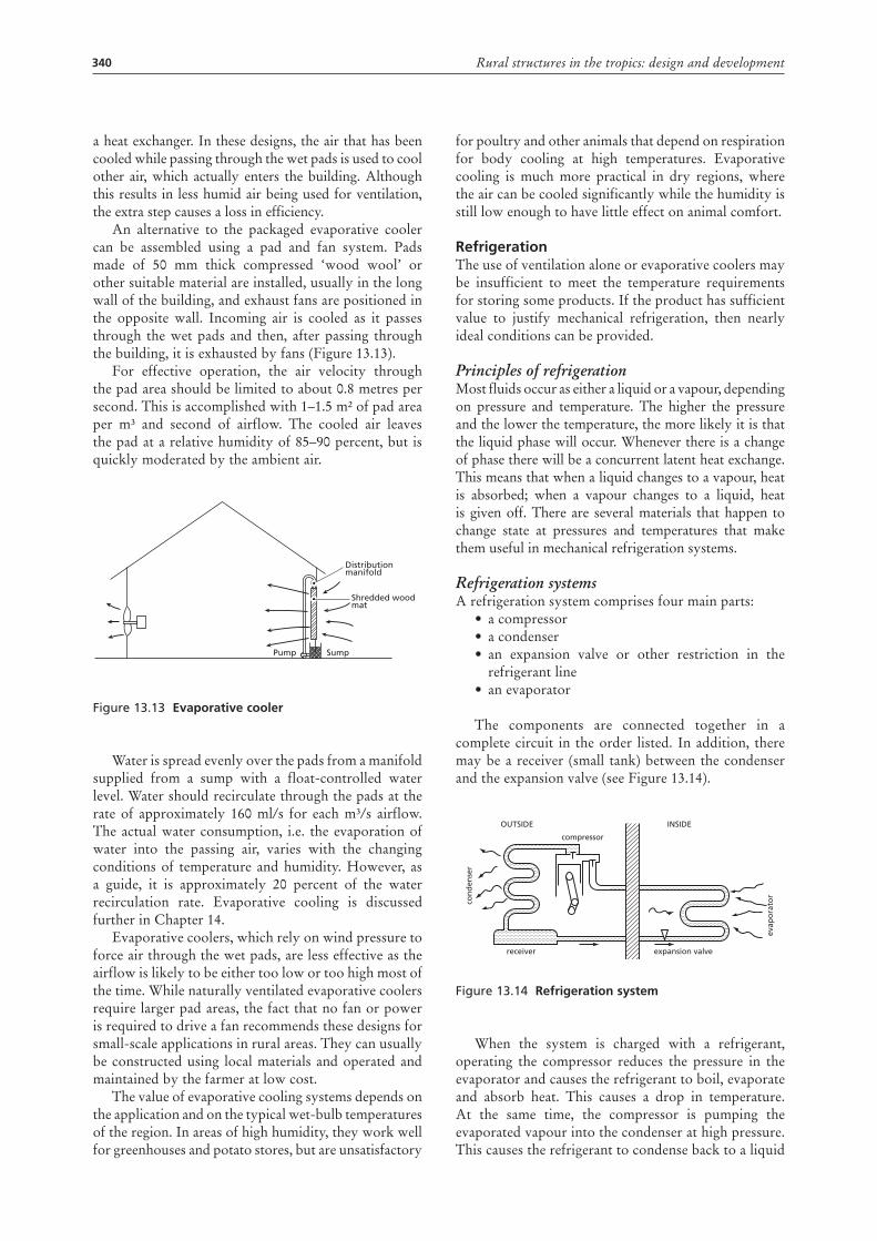
An alternative to the packaged evaporative cooler can be assembled using a pad and fan system. Pads made of 50 mm thick compressed ‘wood wool’ or other suitable material are installed, usually in the long wall of the building, and exhaust fans are positioned in the opposite wall. Incoming air is cooled as it passes through the wet pads and then, after passing through the building, it is exhausted by fans (Figure 13.13).
For effective operation, the air velocity through the pad area should be limited to about 0.8 metres per second. This is accomplished with 1–1.5 m² of pad area per m³ and second of airflow. The cooled air leaves the pad at a relative humidity of 85–90 percent, but is quickly moderated by the ambient air.
Figure 13.13 evaporative cooler
Water is spread evenly over the pads from a manifold supplied from a sump with a float-controlled water level. Water should recirculate through the pads at the rate of approximately 160 ml/s for each m³/s airflow. The actual water consumption, i.e. the evaporation of water into the passing air, varies with the changing conditions of temperature and humidity. However, as a guide, it is approximately 20 percent of the water recirculation rate. Evaporative cooling is discussed further in Chapter 14.
Evaporative coolers, which rely on wind pressure to force air through the wet pads, are less effective as the airflow is likely to be either too low or too high most of the time. While naturally ventilated evaporative coolers require larger pad areas, the fact that no fan or power is required to drive a fan recommends these designs for small-scale applications in rural areas. They can usually be constructed using local materials and operated and maintained by the farmer at low cost.
The value of evaporative cooling systems depends on the application and on the typical wet-bulb temperatures of the region. In areas of high humidity, they work well for greenhouses and potato stores, but are unsatisfactory
Pump Sump
Shredded woodmat
Distributionmanifold
for poultry and other animals that depend on respiration for body cooling at high temperatures. Evaporative cooling is much more practical in dry regions, where the air can be cooled significantly while the humidity is still low enough to have little effect on animal comfort.
refrigerationThe use of ventilation alone or evaporative coolers may be insufficient to meet the temperature requirements for storing some products. If the product has sufficient value to justify mechanical refrigeration, then nearly ideal conditions can be provided.
Principles of refrigerationMost fluids occur as either a liquid or a vapour, depending on pressure and temperature. The higher the pressure and the lower the temperature, the more likely it is that the liquid phase will occur. Whenever there is a change of phase there will be a concurrent latent heat exchange. This means that when a liquid changes to a vapour, heat is absorbed; when a vapour changes to a liquid, heat is given off. There are several materials that happen to change state at pressures and temperatures that make them useful in mechanical refrigeration systems.
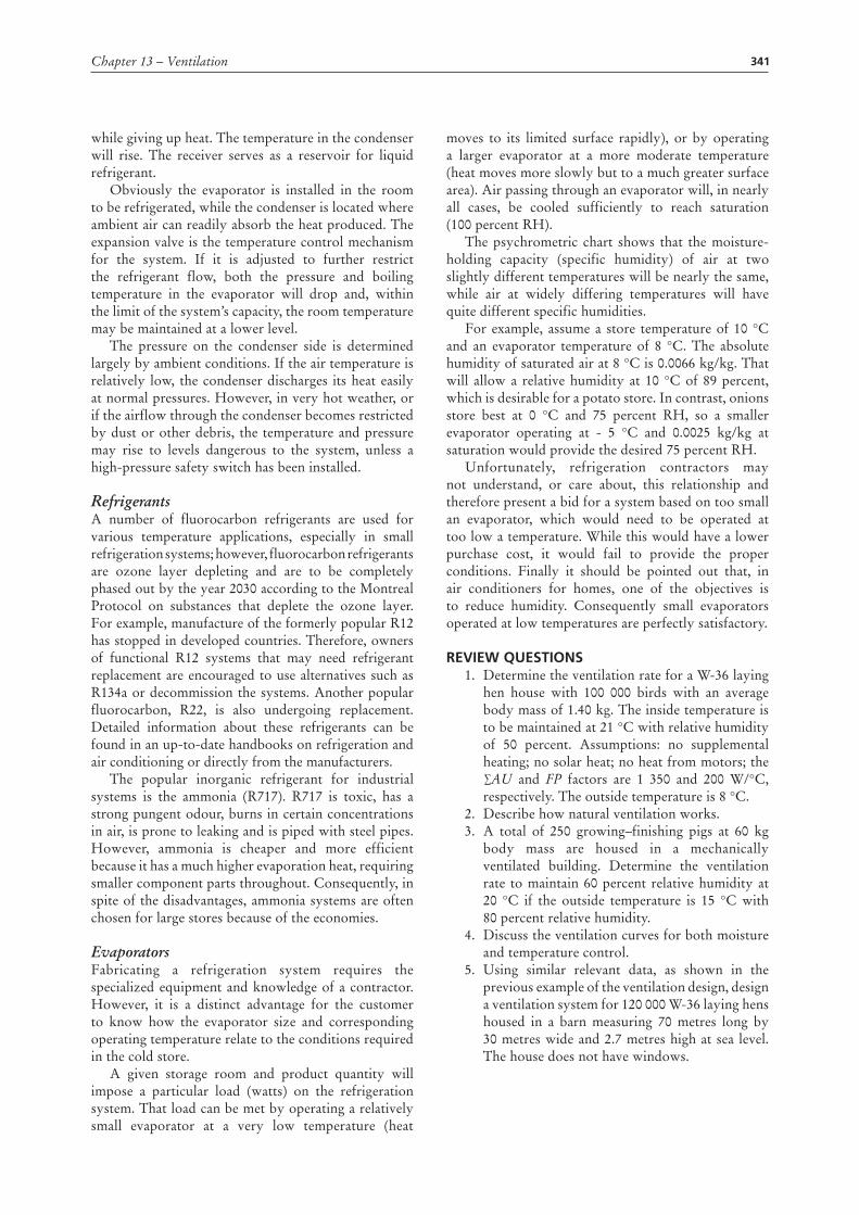
Refrigeration systems A refrigeration system comprises four main parts:
• a compressor• a condenser• an expansion valve or other restriction in the
refrigerant line• an evaporator
The components are connected together in a complete circuit in the order listed. In addition, there may be a receiver (small tank) between the condenser and the expansion valve (see Figure 13.14).
Figure 13.14 refrigeration system
When the system is charged with a refrigerant, operating the compressor reduces the pressure in the evaporator and causes the refrigerant to boil, evaporate and absorb heat. This causes a drop in temperature. At the same time, the compressor is pumping the evaporated vapour into the condenser at high pressure. This causes the refrigerant to condense back to a liquid
OUTSIDE INSIDE
compressor
receiver expansion valve
evap
ora
tor
con
den
ser
341Chapter 13 – Ventilation
while giving up heat. The temperature in the condenser will rise. The receiver serves as a reservoir for liquid refrigerant.
Obviously the evaporator is installed in the room to be refrigerated, while the condenser is located where ambient air can readily absorb the heat produced. The expansion valve is the temperature control mechanism for the system. If it is adjusted to further restrict the refrigerant flow, both the pressure and boiling temperature in the evaporator will drop and, within the limit of the system’s capacity, the room temperature may be maintained at a lower level.
The pressure on the condenser side is determined largely by ambient conditions. If the air temperature is relatively low, the condenser discharges its heat easily at normal pressures. However, in very hot weather, or if the airflow through the condenser becomes restricted by dust or other debris, the temperature and pressure may rise to levels dangerous to the system, unless a high-pressure safety switch has been installed.
RefrigerantsA number of fluorocarbon refrigerants are used for various temperature applications, especially in small refrigeration systems; however, fluorocarbon refrigerants are ozone layer depleting and are to be completely phased out by the year 2030 according to the Montreal Protocol on substances that deplete the ozone layer. For example, manufacture of the formerly popular R12 has stopped in developed countries. Therefore, owners of functional R12 systems that may need refrigerant replacement are encouraged to use alternatives such as R134a or decommission the systems. Another popular fluorocarbon, R22, is also undergoing replacement. Detailed information about these refrigerants can be found in an up-to-date handbooks on refrigeration and air conditioning or directly from the manufacturers.
The popular inorganic refrigerant for industrial systems is the ammonia (R717). R717 is toxic, has a strong pungent odour, burns in certain concentrations in air, is prone to leaking and is piped with steel pipes. However, ammonia is cheaper and more efficient because it has a much higher evaporation heat, requiring smaller component parts throughout. Consequently, in spite of the disadvantages, ammonia systems are often chosen for large stores because of the economies.
EvaporatorsFabricating a refrigeration system requires the specialized equipment and knowledge of a contractor. However, it is a distinct advantage for the customer to know how the evaporator size and corresponding operating temperature relate to the conditions required in the cold store.
A given storage room and product quantity will impose a particular load (watts) on the refrigeration system. That load can be met by operating a relatively small evaporator at a very low temperature (heat
moves to its limited surface rapidly), or by operating a larger evaporator at a more moderate temperature (heat moves more slowly but to a much greater surface area). Air passing through an evaporator will, in nearly all cases, be cooled sufficiently to reach saturation (100 percent RH).
The psychrometric chart shows that the moisture-holding capacity (specific humidity) of air at two slightly different temperatures will be nearly the same, while air at widely differing temperatures will have quite different specific humidities.
For example, assume a store temperature of 10 °C and an evaporator temperature of 8 °C. The absolute humidity of saturated air at 8 °C is 0.0066 kg/kg. That will allow a relative humidity at 10 °C of 89 percent, which is desirable for a potato store. In contrast, onions store best at 0 °C and 75 percent RH, so a smaller evaporator operating at - 5 °C and 0.0025 kg/kg at saturation would provide the desired 75 percent RH.
Unfortunately, refrigeration contractors may not understand, or care about, this relationship and therefore present a bid for a system based on too small an evaporator, which would need to be operated at too low a temperature. While this would have a lower purchase cost, it would fail to provide the proper conditions. Finally it should be pointed out that, in air conditioners for homes, one of the objectives is to reduce humidity. Consequently small evaporators operated at low temperatures are perfectly satisfactory.
reVIew questIons1. Determine the ventilation rate for a W-36 laying
hen house with 100 000 birds with an average body mass of 1.40 kg. The inside temperature is to be maintained at 21 °C with relative humidity of 50 percent. Assumptions: no supplemental heating; no solar heat; no heat from motors; the ∑AU and FP factors are 1 350 and 200 W/°C, respectively. The outside temperature is 8 °C.
2. Describe how natural ventilation works.3. A total of 250 growing–finishing pigs at 60 kg
body mass are housed in a mechanically ventilated building. Determine the ventilation rate to maintain 60 percent relative humidity at 20 °C if the outside temperature is 15 °C with 80 percent relative humidity.
4. Discuss the ventilation curves for both moisture and temperature control.
5. Using similar relevant data, as shown in the previous example of the ventilation design, design a ventilation system for 120 000 W-36 laying hens housed in a barn measuring 70 metres long by 30 metres wide and 2.7 metres high at sea level. The house does not have windows.
342 Rural structures in the tropics: design and development
FurtHer readIngAlbright, L.D. 1990. Environment control for animals
and plants. St. Joseph, Michigan, United States of America, American Society of Agricultural Engineers (ASAE).
American Society of Heating, Refrigeration and Air-conditioning Engineers (ASHRAE). 2005. ASHRAE handbook of fundamentals. Atlanta, Georgia. United States of America.
Building Research Establishment, Overseas Division. 1972. Building in earthquake areas. Overseas Building Notes No. 143. Garston, Watford, United Kingdom.
Burberry, P. 1979. Environment and services. Mitchell’s Building Series. London, B.T. Batsford Ltd.
Chepete, H.J. & Xin, H. 2004. Heat and moisture production of poultry and their housing systems: molting hens. ASHRAE Transactions 110: 274–285.
Chepete, H.J., Xin, H., Puma, M.C. & Gates, R.S. 2004. Heat and moisture production of poultry and their housing systems: pullets and layers. ASHRAE Transactions 110: 286–299.
Midwest Plan Service (MWPS). 1983. Structures and environment handbook. MWPS-33. Iowa State University, Ames, Iowa.
Redding, G.J. 1981. Functional design handbook for Australian farm buildings. Melbourne, Agricultural Engineering Section, University of Melbourne.
United Nations, Department of Economic and Social Affairs. 1975. Low-cost construction resistant to earthquake and hurricanes. New York.
Van Straaten, J.F. 1967. Thermal performance of buildings. Amsterdam, Elsevier.
Whitaker, J.H. 1979. Agricultural buildings and structures. Reston, Virginia, Reston Publishing Co.
343
Chapter 14
Greenhouses
IntroductIonA greenhouse is a structure using natural light within which optimum conditions may be achieved for the propagation and growing of horticultural crops, for plant research, or for isolating plants from diseases or insects. In the 1970s, in the tropical areas of Africa, applications were limited because there were only a few situations in which a greenhouse could be justified owing to the optimum growing conditions required for a high-value crop or a research project. However, as from the 1980s, with the establishment of an export-oriented horticulture industry (Kenya’s horticulture industry is one of its largest foreign-exchange earners), greenhouses are now found in most countries of Africa.
The cost of various greenhouse designs varies greatly and a careful assessment is required to match the requirements for a given enterprise to the cost of the greenhouse. For example, a greenhouse used for all-year flower production can justify the cost of glass, while a greenhouse used for a month or two for starting vegetable plants can only justify a polythene covering.
Location of the greenhouseThe following factors should be considered when deciding where to locate a greenhouse.
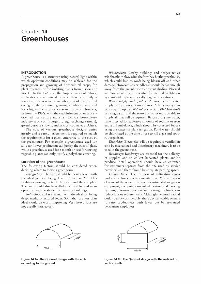
Topography: The land should be nearly level, with the ideal gradient being 1 in 100 to l in 200. This facilitates moving carts of plants around the complex. The land should also be well-drained and located in an open area with no shade from trees or buildings.
Soils: Good soil is essential, with the ideal soil being deep, medium-textured loam. Soils that are less than ideal would be worth improving. Very heavy soils are not usually satisfactory.
Windbreaks: Nearby buildings and hedges act as windbreaks to slow winds before they hit the greenhouse, which could lead to roofs being blown off and other damage. However, any windbreak should be far enough away from the greenhouse to prevent shading. Normal air movement is also essential for natural ventilation systems and to prevent locally stagnant conditions.
Water supply and quality: A good, clean water supply is of paramount importance. A full crop system may require up to 8 400 m³ per hectare (840 litres/m²) in a single year, and the source of water must be able to supply all that will be required. Before using any water, have it tested for excessive amounts of sodium or iron and a pH imbalance, which should be corrected before using the water for plant irrigation. Pond water should be chlorinated at the time of use to kill algae and root-rot organisms.
Electricity: Electricity will be required if ventilation is to be mechanized and if stationary machinery is to be used in the greenhouse.
Roadways: Roadways are essential for the delivery of supplies and to collect harvested plants and/or produce. Retail operations should have an entrance for customers separate from the one used by service providers and there should be adequate parking space.
Labour force: The business of cultivating crops under greenhouses is labour-intensive. Mechanization of some of the operations, such as automated irrigation equipment, computer-controlled heating and cooling systems, automated seeders and potting machines, can reduce labour requirements. Although the initial capital outlay can be considerable, these devices enable owners to raise productivity with fewer but better-trained permanent employees.
Figure 14.1a the Quonset design with the arch extending to the ground
Width
Length
Figure 14.1b the Quonset design with the arch set on vertical walls
Width
Hei
gh
t
Length
344 Rural structures in the tropics: design and development
Types of greenhouse There is a wide variety of greenhouse designs. However, most of these are derived from two basic designs: the Quonset and the A-frame. The Quonset is based on an arched roof that permits stresses on the structure to be efficiently transferred to the ground. Quonset greenhouses are normally available in two basic designs.
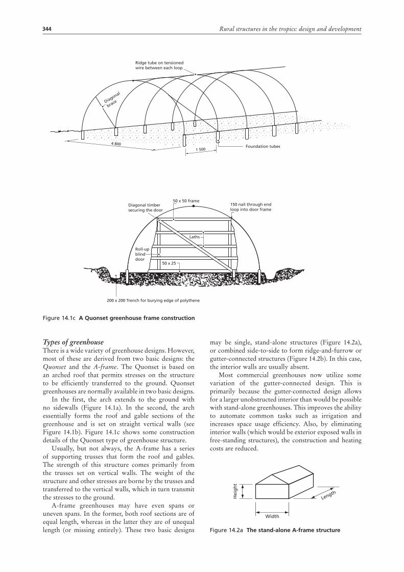
In the first, the arch extends to the ground with no sidewalls (Figure 14.1a). In the second, the arch essentially forms the roof and gable sections of the greenhouse and is set on straight vertical walls (see Figure 14.1b). Figure 14.1c shows some construction details of the Quonset type of greenhouse structure.
Usually, but not always, the A-frame has a series of supporting trusses that form the roof and gables. The strength of this structure comes primarily from the trusses set on vertical walls. The weight of the structure and other stresses are borne by the trusses and transferred to the vertical walls, which in turn transmit the stresses to the ground.
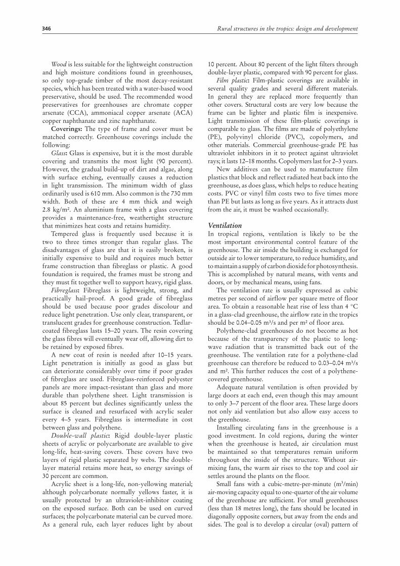
A-frame greenhouses may have even spans or uneven spans. In the former, both roof sections are of equal length, whereas in the latter they are of unequal length (or missing entirely). These two basic designs
may be single, stand-alone structures (Figure 14.2a), or combined side-to-side to form ridge-and-furrow or gutter-connected structures (Figure 14.2b). In this case, the interior walls are usually absent.
Most commercial greenhouses now utilize some variation of the gutter-connected design. This is primarily because the gutter-connected design allows for a larger unobstructed interior than would be possible with stand-alone greenhouses. This improves the ability to automate common tasks such as irrigation and increases space usage efficiency. Also, by eliminating interior walls (which would be exterior exposed walls in free-standing structures), the construction and heating costs are reduced.
Figure 14.2a the stand-alone A-frame structure
Width
Length
Hei
gh
t
Figure 14.1c A Quonset greenhouse frame construction
Foundation tubes
Ridge tube on tensionedwire between each loop
Diagonal
brace
150 nail through endloop into door frame
1 500
4 800
50 x 50 frame
50 x 25
Laths
Roll-upblinddoor
Diagonal timbersecuring the door
200 x 200 Trench for burying edge of polythene

345Chapter 14 – Greenhouses
Figure 14.2b the gutter-connected A-frame structure
There are several potential drawbacks with gutter-connected facilities. As the entire production area is a single space, the ability to maintain different environmental conditions (as is possible using numerous individual structures) is lost. In addition, as the size of the gutter-connected span increases, uniformity and control of light, temperature, airflow and humidity may be reduced.
One way to minimize these drawbacks is to have drop-walls or curtains made of polyethylene film that can be raised or lowered between sections. This allows sections within the structure to be partially isolated so that different temperatures or relative humidity levels can be maintained – if only to a limited degree.
Greenhouse design parametersIncreasingly in recent years, most greenhouses are designed by engineering firms or are constructed from packages developed by engineering firms. The design and all the materials may be provided by the design firm. In many cases, the design firm will also build the structure. However, it is useful to understand the basic design considerations.
Light: It is important for crops being grown in a greenhouse to receive the optimum amount of light, not only when the skies are clear (direct light), but also when they are cloudy (diffuse light). The shape and construction of the greenhouse should be such that it allows the best possible entry of light. The size and cross-section of all the load-bearing members have a pronounced effect on light transmission.
The gutters of multispan roofs produce considerable shade, and similarly, in widespan greenhouses, the heavier roof trusses tend to cause more shading. Thus, open trusses with narrow-section members are desirable. Light colours and reflective surfaces improve light transmission. In spite of a good design for natural light, artificial lighting may be needed for the production of photoperiod-sensitive plants.
Design loads: The greenhouse should be able to withstand both the dead load and the live load. The dead load includes the weight of the structure, framing, glazing, permanent equipment, heating and cooling units and vents. The live load includes the weight of people working on the roof, hanging plants and wind loads.
The foundation: The foundation must support the structure and transfer loads to the ground. In some cases, the structure may be set on an intact concrete foundation or slab. Supports may be bolted onto the foundation. In other cases, whether or not a concrete
foundation is present, the structure may be supported by vertical beams placed on concrete footings.
Orientation: Within the latitudes found in the tropics it is desirable to orient the ridges of greenhouses north–south to reduce the overall shading by the framing members. This is true for all types of frame, including multi-span greenhouses.
Size: While multi-span blocks of 3.2 metres each are the least expensive to build, wider spans allow somewhat better light transmission. Furthermore, the general management in wider greenhouses (movement of machines, optimum cropping layouts, etc.) may justify the extra cost. As a general rule, the cost is lowest when the length is four to five times the span width. This is particularly true with wide-span greenhouses.
Height: The height of a greenhouse should be sufficient for the operation of machinery and the comfort of the workers. An increase in height improves natural ventilation during still conditions and makes it easier to obtain the desired plant climate. However, with very high roofs, maintenance becomes more difficult. Gutter heights of 2.8–3.0 metres are recommended for multi-span greenhouses to allow machines to move freely. In single-span greenhouses, eave height should be at least 2 metres to provide unrestricted work space.
Structural materialsThese can be grouped into floors, frames and coverings.
Floors: Floors may be constructed of porous concrete, Portland cement, gravel or compacted clay covered with a strong polypropylene fabric. Porous concrete is usually strong enough to bear most loads encountered in greenhouse situations, and allows for drainage through the surface. Portland cement is more expensive and does not allow drainage through the surface. However, Portland cement might be desirable in traffic areas where heavy loads occur.
Concrete floors should have a slight gradient to promote drainage and prevent puddling of water. Gravel is inexpensive and allows drainage, but can allow the growth of weeds and may not accommodate all types of equipment. Although polypropylene fabric may be a low-cost alternative, the floor can become uneven over time and can cause puddling and algae growth.
Frames: Greenhouse frames range from simple to complex, depending on the imagination of the designer and the engineering requirements. Greenhouses are generally built of steel, aluminium or wood and are glazed with good-quality glass, clear polythene sheet, or fibreglass-reinforced polyester panels.
Steel must be galvanized after fabrication, as any welding or drilling breaks the galvanized layer. Steel is cheaper than aluminium and is ideal for the main roof frame.
Aluminium is very resistant to corrosion and is easily formed into complex sections. While it is expensive, it is most suitable for glazing bars. As it cannot be welded economically, bolted construction is used.
346 Rural structures in the tropics: design and development
Wood is less suitable for the lightweight construction and high moisture conditions found in greenhouses, so only top-grade timber of the most decay-resistant species, which has been treated with a water-based wood preservative, should be used. The recommended wood preservatives for greenhouses are chromate copper arsenate (CCA), ammoniacal copper arsenate (ACA) copper naphthanate and zinc naphthanate.
Coverings: The type of frame and cover must be matched correctly. Greenhouse coverings include the following:
Glass: Glass is expensive, but it is the most durable covering and transmits the most light (90 percent). However, the gradual build-up of dirt and algae, along with surface etching, eventually causes a reduction in light transmission. The minimum width of glass ordinarily used is 610 mm. Also common is the 730 mm width. Both of these are 4 mm thick and weigh 2.8 kg/m². An aluminium frame with a glass covering provides a maintenance-free, weathertight structure that minimizes heat costs and retains humidity.
Tempered glass is frequently used because it is two to three times stronger than regular glass. The disadvantages of glass are that it is easily broken, is initially expensive to build and requires much better frame construction than fibreglass or plastic. A good foundation is required, the frames must be strong and they must fit together well to support heavy, rigid glass.
Fibreglass: Fibreglass is lightweight, strong, and practically hail-proof. A good grade of fibreglass should be used because poor grades discolour and reduce light penetration. Use only clear, transparent, or translucent grades for greenhouse construction. Tedlar-coated fibreglass lasts 15–20 years. The resin covering the glass fibres will eventually wear off, allowing dirt to be retained by exposed fibres.
A new coat of resin is needed after 10–15 years. Light penetration is initially as good as glass but can deteriorate considerably over time if poor grades of fibreglass are used. Fibreglass-reinforced polyester panels are more impact-resistant than glass and more durable than polythene sheet. Light transmission is about 85 percent but declines significantly unless the surface is cleaned and resurfaced with acrylic sealer every 4–5 years. Fibreglass is intermediate in cost between glass and polythene.
Double-wall plastic: Rigid double-layer plastic sheets of acrylic or polycarbonate are available to give long-life, heat-saving covers. These covers have two layers of rigid plastic separated by webs. The double-layer material retains more heat, so energy savings of 30 percent are common.
Acrylic sheet is a long-life, non-yellowing material; although polycarbonate normally yellows faster, it is usually protected by an ultraviolet-inhibitor coating on the exposed surface. Both can be used on curved surfaces; the polycarbonate material can be curved more. As a general rule, each layer reduces light by about
10 percent. About 80 percent of the light filters through double-layer plastic, compared with 90 percent for glass.
Film plastic: Film-plastic coverings are available in several quality grades and several different materials. In general they are replaced more frequently than other covers. Structural costs are very low because the frame can be lighter and plastic film is inexpensive. Light transmission of these film-plastic coverings is comparable to glass. The films are made of polyethylene (PE), polyvinyl chloride (PVC), copolymers, and other materials. Commercial greenhouse-grade PE has ultraviolet inhibitors in it to protect against ultraviolet rays; it lasts 12–18 months. Copolymers last for 2–3 years.
New additives can be used to manufacture film plastics that block and reflect radiated heat back into the greenhouse, as does glass, which helps to reduce heating costs. PVC or vinyl film costs two to five times more than PE but lasts as long as five years. As it attracts dust from the air, it must be washed occasionally.
VentilationIn tropical regions, ventilation is likely to be the most important environmental control feature of the greenhouse. The air inside the building is exchanged for outside air to lower temperature, to reduce humidity, and to maintain a supply of carbon dioxide for photosynthesis. This is accomplished by natural means, with vents and doors, or by mechanical means, using fans.
The ventilation rate is usually expressed as cubic metres per second of airflow per square metre of floor area. To obtain a reasonable heat rise of less than 4 °C in a glass-clad greenhouse, the airflow rate in the tropics should be 0.04–0.05 m³/s and per m² of floor area.
Polythene-clad greenhouses do not become as hot because of the transparency of the plastic to long-wave radiation that is transmitted back out of the greenhouse. The ventilation rate for a polythene-clad greenhouse can therefore be reduced to 0.03–0.04 m³/s and m². This further reduces the cost of a polythene-covered greenhouse.
Adequate natural ventilation is often provided by large doors at each end, even though this may amount to only 3–7 percent of the floor area. These large doors not only aid ventilation but also allow easy access to the greenhouse.
Installing circulating fans in the greenhouse is a good investment. In cold regions, during the winter when the greenhouse is heated, air circulation must be maintained so that temperatures remain uniform throughout the inside of the structure. Without air-mixing fans, the warm air rises to the top and cool air settles around the plants on the floor.
Small fans with a cubic-metre-per-minute (m3/min) air-moving capacity equal to one-quarter of the air volume of the greenhouse are sufficient. For small greenhouses (less than 18 metres long), the fans should be located in diagonally opposite corners, but away from the ends and sides. The goal is to develop a circular (oval) pattern of
347Chapter 14 – Greenhouses
air movement. In addition, the fans should be operated continuously during the winter and turned off during the summer when the greenhouse will need to be ventilated.
CoolingAs a result of the long hot season in the tropics, the greenhouse must be cooled to achieve the desired conditions. Glazing materials allow shorter-wavelength radiation (i.e. visible light) to pass through, but long-wavelength radiation such as infrared (heat) is trapped inside the greenhouse. The temperature inside a greenhouse may be up to 20–30 oC higher than the ambient temperature outside (hence the greenhouse effect). Owing to the greenhouse effect, greenhouses require both summer and winter cooling systems.
Summer cooling systemsPassive systemsVenting: High summer temperatures mean that there is a constant need to remove heat from the greenhouse. This may be accomplished by replacing existing air in the greenhouse with cooler air from outside the structure. If outside temperatures are low enough, and if temperatures in the greenhouses are not excessive, warm air may be passively exhausted through roof vents.
The upward and outward movement of warm air pulls in cool air from side- or end-vents. This system is most effective in the winter, spring and autumn. It is limited in its effectiveness for summer cooling, as the incoming solar load and the outside air temperature may exceed the capabilities of this system.
Shading: Shading is another method of passive cooling used to reduce the amount of light transmitted into the greenhouse, thereby reducing the solar load. In glass houses, shading may be achieved simply by applying water-based whitewash to the inside of the roof to cut down light transmission. When the weather conditions are steady and reliable, whitewash is cheap and effective and easily washed off when it is no longer needed. Whitewash seems particularly appropriate for shading in tropical areas.
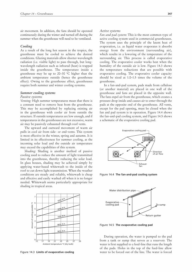
Figure 14.3 Limits of evaporative cooling
Ambient temperature °C [dry bulb]
Am
ou
nt
of
coo
ling
po
ssib
le °
C
150
1
2
3
4
5
6
7
17 19 21
90% R.H.
80% R.H.
70% R.H.
60% R.H.
50% R.H.
23 25 27 29
Active systemsFan-and-pad system: This is the most common type of active cooling system used in commercial greenhouses. The system uses the principle of the latent heat of evaporation, i.e. as liquid water evaporates it absorbs energy from the environment (surrounding air), which results in a lowering of the temperature of the surrounding air. This process is called evaporative cooling. The evaporative cooler works best when the humidity of the outside air is low. Figure 14.3 shows the temperature reductions that are possible with evaporative cooling. The evaporative cooler capacity should be sized at 1.0–1.5 times the volume of the greenhouse.
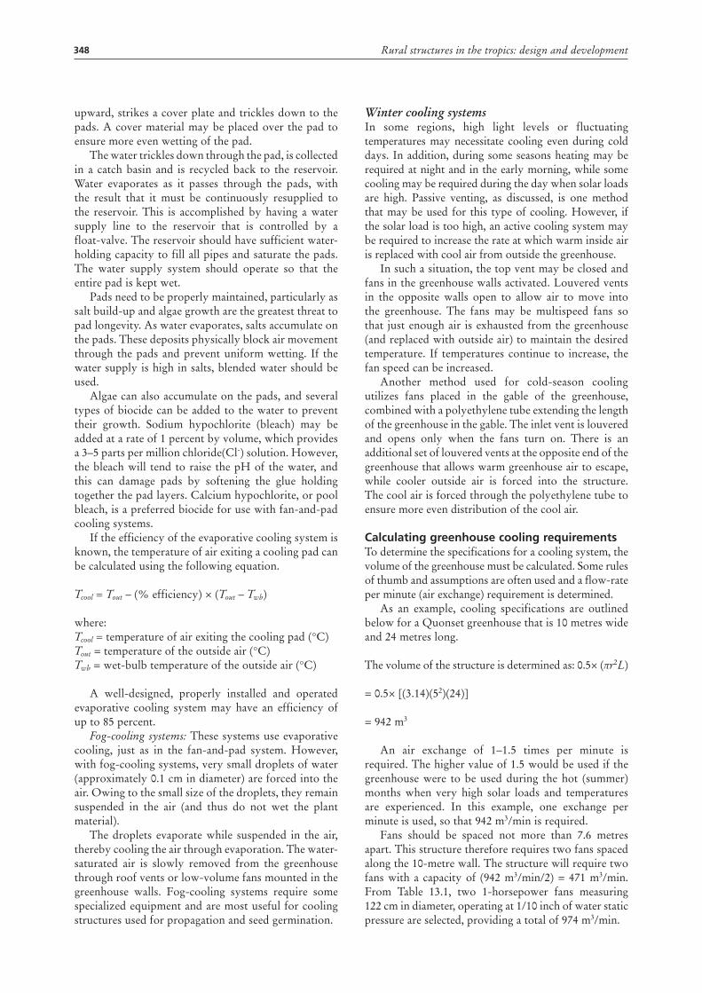
In a fan-and-pad system, pads made from cellulose (or another material) are placed in one wall of the greenhouse and fans are placed in the opposite wall. The fans expel air from the greenhouse, which creates a pressure drop inside and causes air to enter through the pads at the opposite end of the greenhouse. All vents, except for the pad opening, must be closed when the fan and pad system is in operation. Figure 14.4 shows the fan-and-pad cooling system, and Figure 14.5 shows a schematic of the evaporative cooling pad.
Figure 14.4 the fan-and-pad cooling system
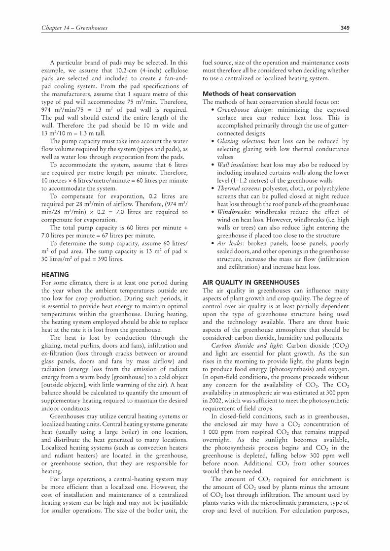
Figure 14.5 the evaporative cooling pad
During operation, the water is pumped to the pad from a tank or sump that serves as a reservoir. The water is first supplied to a feed-line that runs the length of the pads. Holes in the top of the feed-line allow water to be forced out of the line. The water is forced
Evaporative cooling pad
Direction of air flow
Exhaustfan
Water distribution pipe
Evaporativecooling pad To sump
Return gutter
348 Rural structures in the tropics: design and development
upward, strikes a cover plate and trickles down to the pads. A cover material may be placed over the pad to ensure more even wetting of the pad.
The water trickles down through the pad, is collected in a catch basin and is recycled back to the reservoir. Water evaporates as it passes through the pads, with the result that it must be continuously resupplied to the reservoir. This is accomplished by having a water supply line to the reservoir that is controlled by a float-valve. The reservoir should have sufficient water-holding capacity to fill all pipes and saturate the pads. The water supply system should operate so that the entire pad is kept wet.
Pads need to be properly maintained, particularly as salt build-up and algae growth are the greatest threat to pad longevity. As water evaporates, salts accumulate on the pads. These deposits physically block air movement through the pads and prevent uniform wetting. If the water supply is high in salts, blended water should be used.
Algae can also accumulate on the pads, and several types of biocide can be added to the water to prevent their growth. Sodium hypochlorite (bleach) may be added at a rate of 1 percent by volume, which provides a 3–5 parts per million chloride(Cl-) solution. However, the bleach will tend to raise the pH of the water, and this can damage pads by softening the glue holding together the pad layers. Calcium hypochlorite, or pool bleach, is a preferred biocide for use with fan-and-pad cooling systems.
If the efficiency of the evaporative cooling system is known, the temperature of air exiting a cooling pad can be calculated using the following equation.
Tcool = Tout – (% efficiency) × (Tout – Twb)
where:Tcool = temperature of air exiting the cooling pad (°C)Tout = temperature of the outside air (°C)Twb = wet-bulb temperature of the outside air (°C)
A well-designed, properly installed and operated evaporative cooling system may have an efficiency of up to 85 percent.
Fog-cooling systems: These systems use evaporative cooling, just as in the fan-and-pad system. However, with fog-cooling systems, very small droplets of water (approximately 0.1 cm in diameter) are forced into the air. Owing to the small size of the droplets, they remain suspended in the air (and thus do not wet the plant material).
The droplets evaporate while suspended in the air, thereby cooling the air through evaporation. The water-saturated air is slowly removed from the greenhouse through roof vents or low-volume fans mounted in the greenhouse walls. Fog-cooling systems require some specialized equipment and are most useful for cooling structures used for propagation and seed germination.
Winter cooling systemsIn some regions, high light levels or fluctuating temperatures may necessitate cooling even during cold days. In addition, during some seasons heating may be required at night and in the early morning, while some cooling may be required during the day when solar loads are high. Passive venting, as discussed, is one method that may be used for this type of cooling. However, if the solar load is too high, an active cooling system may be required to increase the rate at which warm inside air is replaced with cool air from outside the greenhouse.
In such a situation, the top vent may be closed and fans in the greenhouse walls activated. Louvered vents in the opposite walls open to allow air to move into the greenhouse. The fans may be multispeed fans so that just enough air is exhausted from the greenhouse (and replaced with outside air) to maintain the desired temperature. If temperatures continue to increase, the fan speed can be increased.
Another method used for cold-season cooling utilizes fans placed in the gable of the greenhouse, combined with a polyethylene tube extending the length of the greenhouse in the gable. The inlet vent is louvered and opens only when the fans turn on. There is an additional set of louvered vents at the opposite end of the greenhouse that allows warm greenhouse air to escape, while cooler outside air is forced into the structure. The cool air is forced through the polyethylene tube to ensure more even distribution of the cool air.
calculating greenhouse cooling requirements To determine the specifications for a cooling system, the volume of the greenhouse must be calculated. Some rules of thumb and assumptions are often used and a flow-rate per minute (air exchange) requirement is determined.
As an example, cooling specifications are outlined below for a Quonset greenhouse that is 10 metres wide and 24 metres long.
The volume of the structure is determined as: 0.5× (πr2L)
= 0.5× [(3.14)(52)(24)]
= 942 m3
An air exchange of 1–1.5 times per minute is required. The higher value of 1.5 would be used if the greenhouse were to be used during the hot (summer) months when very high solar loads and temperatures are experienced. In this example, one exchange per minute is used, so that 942 m3/min is required.
Fans should be spaced not more than 7.6 metres apart. This structure therefore requires two fans spaced along the 10-metre wall. The structure will require two fans with a capacity of (942 m3/min/2) = 471 m3/min. From Table 13.1, two 1-horsepower fans measuring 122 cm in diameter, operating at 1/10 inch of water static pressure are selected, providing a total of 974 m3/min.
349Chapter 14 – Greenhouses
A particular brand of pads may be selected. In this example, we assume that 10.2-cm (4-inch) cellulose pads are selected and included to create a fan-and-pad cooling system. From the pad specifications of the manufacturers, assume that 1 square metre of this type of pad will accommodate 75 m3/min. Therefore, 974 m3/min/75 = 13 m2 of pad wall is required. The pad wall should extend the entire length of the wall. Therefore the pad should be 10 m wide and 13 m2/10 m = 1.3 m tall.
The pump capacity must take into account the water flow volume required by the system (pipes and pads), as well as water loss through evaporation from the pads.
To accommodate the system, assume that 6 litres are required per metre length per minute. Therefore, 10 metres × 6 litres/metre/minute = 60 litres per minute to accommodate the system.
To compensate for evaporation, 0.2 litres are required per 28 m3/min of airflow. Therefore, (974 m3/min/28 m3/min) × 0.2 = 7.0 litres are required to compensate for evaporation.
The total pump capacity is 60 litres per minute + 7.0 litres per minute = 67 litres per minute.
To determine the sump capacity, assume 60 litres/m2 of pad area. The sump capacity is 13 m2 of pad × 30 litres/m2 of pad = 390 litres.
HEAtInG For some climates, there is at least one period during the year when the ambient temperatures outside are too low for crop production. During such periods, it is essential to provide heat energy to maintain optimal temperatures within the greenhouse. During heating, the heating system employed should be able to replace heat at the rate it is lost from the greenhouse.
The heat is lost by conduction (through the glazing, metal purlins, doors and fans), infiltration and ex-filtration (loss through cracks between or around glass panels, doors and fans by mass airflow) and radiation (energy loss from the emission of radiant energy from a warm body [greenhouse] to a cold object [outside objects], with little warming of the air). A heat balance should be calculated to quantify the amount of supplementary heating required to maintain the desired indoor conditions.
Greenhouses may utilize central heating systems or localized heating units. Central heating systems generate heat (usually using a large boiler) in one location, and distribute the heat generated to many locations. Localized heating systems (such as convection heaters and radiant heaters) are located in the greenhouse, or greenhouse section, that they are responsible for heating.
For large operations, a central-heating system may be more efficient than a localized one. However, the cost of installation and maintenance of a centralized heating system can be high and may not be justifiable for smaller operations. The size of the boiler unit, the
fuel source, size of the operation and maintenance costs must therefore all be considered when deciding whether to use a centralized or localized heating system.
Methods of heat conservation The methods of heat conservation should focus on:
•Greenhouse design: minimizing the exposed surface area can reduce heat loss. This is accomplished primarily through the use of gutter-connected designs
•Glazing selection: heat loss can be reduced by selecting glazing with low thermal conductance values
•Wall insulation: heat loss may also be reduced by including insulated curtains walls along the lower level (1–1.2 metres) of the greenhouse walls
•Thermal screens: polyester, cloth, or polyethylene screens that can be pulled closed at night reduce heat loss through the roof panels of the greenhouse
•Windbreaks: windbreaks reduce the effect of wind on heat loss. However, windbreaks (i.e. high walls or trees) can also reduce light entering the greenhouse if placed too close to the structure
•Air leaks: broken panels, loose panels, poorly sealed doors, and other openings in the greenhouse structure, increase the mass air flow (infiltration and exfiltration) and increase heat loss.
AIr QuALIty In GrEEnHousEs The air quality in greenhouses can influence many aspects of plant growth and crop quality. The degree of control over air quality is at least partially dependent upon the type of greenhouse structure being used and the technology available. There are three basic aspects of the greenhouse atmosphere that should be considered: carbon dioxide, humidity and pollutants.
Carbon dioxide and light: Carbon dioxide (CO2) and light are essential for plant growth. As the sun rises in the morning to provide light, the plants begin to produce food energy (photosynthesis) and oxygen. In open-field conditions, the process proceeds without any concern for the availability of CO2. The CO2 availability in atmospheric air was estimated at 300 ppm in 2002, which was sufficient to meet the photosynthetic requirement of field crops.
In closed-field conditions, such as in greenhouses, the enclosed air may have a CO2 concentration of 1 000 ppm from respired CO2 that remains trapped overnight. As the sunlight becomes available, the photosynthesis process begins and CO2 in the greenhouse is depleted, falling below 300 ppm well before noon. Additional CO2 from other sources would then be needed.
The amount of CO2 required for enrichment is the amount of CO2 used by plants minus the amount of CO2 lost through infiltration. The amount used by plants varies with the microclimatic parameters, type of crop and level of nutrition. For calculation purposes,
350 Rural structures in the tropics: design and development
the general range varies from 0.6–1.2 litres per hour per m2 of floor area. The loss of CO2 is greater in glass than in plastic film greenhouses as a result of differences in infiltration rates. The infiltration loss can be determined using the expression given below:
IL = Vg × N × 10-6 × (DL – 300)
where:IL = infiltration loss (m3/h)Vg = volume of greenhouse (m3)N = number of air changes per hourDL = designed CO2 level (ppm).
The CO2 in the greenhouse is replenished through ventilation. As CO2 and light complement each other, electric lighting combined with the injection of CO2
is used to increase yields of vegetable and flowering crops. Bottled CO2, dry ice and combustion of sulphur-free fuels can be used as CO2 sources. Commercial greenhouses use such methods.
Relative humidity: High humidity promotes the development of certain diseases (e.g. black spot and powdery mildew), as well as various physiological abnormalities (e.g. leaf-edge burn in poinsettia and blossom-end rot of tomatoes) in some greenhouse crops. In addition, high humidity can increase condensation on the inside of the glazing, reducing light levels and causing water to drip onto plants.
During the summer, vents are usually open and the ambient relative humidity outdoors is the humidity at which the greenhouse will be maintained (although the relative humidity in the greenhouse may still be higher than that outside because of evaporation–transpiration). However, during cool months when vents are closed and heating is required, very high relative humidities can occur. To control this, growers will periodically increase greenhouse temperatures to saturate the air with water vapour and then vent the warm saturated air out of the greenhouse.
Pollutants and toxic substances: Carbon monoxide is dangerous to humans. It is generated by malfunctioning heaters and other machinery with internal combustion engines. Unit heaters without internal heat exchangers should be avoided, as they emit exhaust and carbon monoxide directly into the structure they are intended to heat. Malfunctioning heaters may also generate ethylene, which is damaging to plants. Numerous chemicals, including herbicides, paints and cleaning materials, may release potentially damaging volatile chemicals and caution should be exercised when using them in or around greenhouses.
Equipment maintenance Proper maintenance of all equipment used in the greenhouse is critical. Maintenance should include appropriate cleaning and checking of the air intake, exhaust system, fuel lines and fans. The burner system
and the heat exchanger should be checked periodically. Calibration of the thermostat, as well as checks of the structural integrity, and any other maintenance items prescribed by the manufacturer on all pieces of equipment used, should be undertaken periodically.
rEvIEw QuEstIons1. Discuss the factors that must be considered when
designing a greenhouse.2. Calculate how far apart the fans should be spaced
in a greenhouse given a fan capacity of 700 m3/min, ventilation rate of 4.0 m3/min/m2 and a distance between the fan and outlet of 45 metres.
3. Outline the procedure for determining the size of an evaporative cooling pad and the capacity of the cooling water tank in a greenhouse.
4. Describe the evaporative cooling phenomenon.5. Identify a greenhouse near you and perform an
energy analysis on it to determine whether it requires heating or cooling.
FurtHEr rEAdInGAldrich, R.A. & Bartok Jr., J.W. 1994. Greenhouse
engineering. Ithaca, New York, United States of America, Natural Resource, Agriculture and Engineering Service (NRAES-33), Cooperative Extension.
American Society of Heating, Refrigerating and Air-conditioning Engineers (ASHRAE). 1995. HVAC applications. ASHRAE handbook. Atlanta, Georgia, United States of America.
FAO. 1960. Agricultural machinery workshops: design, equipment and management, FAO Agricultural Development Paper No. 66. Rome.
FAO. 1982. Plastic greenhouses for warm climates, by K. Virhammar. FAO Agricultural Services Bulletin No. 48. Rome
FAO. 1999. Greenhouses and shelter structures for tropical regions, by C. von Zabeltitz & W.O. Baudoin. FAO Plant Production and Protection Paper No. 154. Rome, Italy.
Iowa State University (Cooperative Extension Service). 1980. Planning and equipping a service center for your farm. Ames, Iowa, United States of America.
Noton, N.H. 1982. Farm buildings. Reading, United Kingdom, College of Estate Management.
Tiwari, G.N. 2003. Greenhouse technology for controlled environment. Pangbourne, United Kingdom, Alpha Science International Ltd.
Whitaker, J.H. 1979. Agricultural buildings and structures, Reston, Virginia, Reston Publishing Co.

351
Chapter 15
Handling semi-perishable and perishable crops
Semi-periSHable cropSFood crops fall into two broad categories: perishable crops and non-perishable crops. This normally refers to the rate at which a crop deteriorates after harvest and thus the length of time it can be stored. While some crops fall clearly into one or other category, others are less easy to categorize. For example, cereal grains can be stored for over a year and are considered to be non-perishable, whereas tomatoes are perishable crops and, when picked fresh, will deteriorate in a few days. However, tubers, such as potatoes, may be successfully stored for periods extending to several months.
Although there are methods for preserving many of the perishable crops, such as canning and freeze-drying, these are normally industrialized processes and are not found on farms. However, it is possible to apply farm-scale methods of preservation to cereals and pulses, as well as the less perishable crops such as potatoes. To do this successfully, it is necessary to know the ways in which a crop can deteriorate, and hence the methods for controlling this process.
Crops may need conditioning at harvest time to make them storable, and they may also require periodic inspection and care during the storage period. The viability of seed must be maintained and susceptibility to damage by fungal and insect pests must be minimized.
In contrast to grain, crops such as potatoes, yams, carrots and onions are more perishable and require carefully managed storage conditions to maintain top quality. While market value is seldom great enough to justify the expense of ideal levels of temperature and humidity control, first the desired conditions will be discussed and then various methods of achieving levels as close to ideal as is economically justifiable will be described.
propertiesThe properties of the many horticultural crops are far more varied than those of grains and pulses. This in turn results in highly varied storage characteristics. For example, yams and potatoes can be stored adequately for several months, while cassava, if not processed, can be kept for only a few days without deterioration.
The initial moisture content after harvest is much higher in these mature crops than in grains. With grains, a loss of moisture is desirable for storage and does not affect the subsequent use of the crop. This is not the case with fruits and vegetables. Loss of moisture may
cause the crop to become unmarketable. Yet, with high moisture content, storage of these crops is more difficult because there is a greater likelihood of insect and fungal damage.
Whereas lowering the moisture content of grain inhibits sprouting without affecting viability, the high-moisture vegetable crops, which cannot be allowed to dry out, are more prone to sprouting. However, there is generally a period of dormancy following harvest that can be used to good advantage.
Perishable and semi-perishable crops are living organisms and, as such, continue to respire. Consequently, any storage will need ventilation to remove the heat and moisture of respiration and to prevent condensation on cool surfaces.
Fruits and vegetables are nearly always susceptible to physical damage such as bruising, cutting and cracking. Much of this results from dropping the fruits or tubers onto hard surfaces or onto other fruits and tubers while they are being loaded into containers or bins. In many cases, 200–300 mm is the maximum safe drop.
Further losses can occur if the heat of respiration is allowed to cause a temperature rise. For example, ‘black heart’ in potatoes is a serious problem resulting from high temperatures under storage conditions. In contrast, low temperatures approaching freezing produce a characteristic sweetening in potatoes.
Losses can also be caused by disease. This tends to be worse if the crop has been damaged, allowing the organisms that cause disease to enter through surface cuts and cracks. Removal of soils adhering to the crop and careful loading before storage can help to reduce this problem.
Storage requirements for potatoes and other horticultural cropsPotatoes are the most commonly stored root crop, for which the greatest amount of research has been conducted into ideal storage requirements. However, very similar facilities and operating conditions are suitable for several other crops with varying perishability characteristics. Although the following sections deal primarily with potatoes, much of the information, including the storage facilities described, also applies to other semiperishable crops.
As mentioned, some bruising and cutting of the tubers is likely to occur during harvesting. These fresh wounds provide an ideal entry point for disease and rot

352 Rural structures in the tropics: design and development
organisms. The infection can be minimized by storing the potatoes for the first 1–2 weeks at a temperature of 13–20 °C and a relative humidity of 90–95 percent. During this curing period the skin toughens, making the tubers much less subject to further injury or disease.
Potatoes are naturally dormant for about 2 months. However, it is often necessary to store them for longer periods of time by extending the dormancy period and by keeping shrinkage to a minimum. Temperature and humidity are important factors in this respect. Suitable temperatures for long-term storage are related to the eventual use of the potatoes.
For seed stock, temperatures of 3–5 °C will delay sprouting for up to 8 months. For ware potatoes, 4–8 °C will allow 4–8 months of storage without serious sprouting, while lower temperatures increase the risk of sweetening, that is, the conversion of starch to sugar. Finally, for processing potatoes, a minimum temperature of 7–10 °C is required in order to prevent discoloration and to keep sweetening to an absolute minimum. In stores with higher temperatures, it is possible to control sprouting in ware and processing potatoes for up to 6–8 months by using a sprout-suppressant chemical.
The relative humidity (RH) of the air in the store is of great importance. Low RH will lead to shrinkage and weight loss, while excessively high RH will cause condensation on the surfaces. This is undesirable because free water on the potatoes greatly increases the possibility of rot and the spread of disease. A potato tuber comprises roughly 80 percent water and, strictly speaking, air is in equilibrium with the tuber at a relative humidity of 98 percent. However, in practice the relative humidity is kept between 90 percent and 96 percent, to avoid condensation.
Potatoes exposed to direct or indirect sunlight will turn green and develop a bitter taste, which is poisonous and makes the tubers unsuitable for human consumption. Stores should therefore have no windows and ventilation openings should have light traps.
Potatoes that have been held at low temperatures tend to be brittle and subject to considerable damage when being handled. If the store has been maintained at low temperatures throughout the storage period, it is best to warm the store to about 10 °C for a few days prior to removing the potatoes.
Storage without buildings
Delayed harvestThe simplest form of storage for some crops is to leave them in the ground and harvest them only as required. There is a risk of pest and rodent damage, but any deterioration that may take place after harvest may exceed field losses; hence delayed harvest is a reasonable choice. This is particularly useful for cassava, where field deterioration is normally substantially less than post-harvest losses even for short-term storage. On the other hand, some crops deteriorate substantially in
quality if left in the ground beyond a certain stage. For example, carrots tend to become tough and woody.
ClampIn areas that have low mean soil temperatures, a simple ground clamp (Figure 15.1) may be suitable, especially for potatoes. The potatoes are piled on the ground in a long row and covered with 150–200 mm of straw or coarse grass. Chicken wire is laid all around the base to protect against rodents, and then soil is dug out around the pile and placed on the straw. This store is not likely to be satisfactory for more than a month or two unless the soil temperature is near 10 °C and air temperatures at night are 10 °C or lower. To control soil pests, the ground can be treated with an insecticide before the clamp is made.
Figure 15.1 Simple root-crop clamp
Covered clampAnother simple solution for short-term storage is the covered clamp (see Figure 15.2) consisting of a raised platform on which the potatoes are heaped and then covered with 10 cm of grass or straw. Air is free to circulate through both produce and straw. A thatch roof overhead provides shade to help reduce daytime temperatures. Protection from rodents will be required.
Figure 15.2 covered clamp raised from the ground
Drainage trench
150 mm
150 mm
Crop
1 to 2∙5 m wide
Rodent protection wire netting buriedand turned outwards
15−20 cm Straw orcourse grass
Sides and endsleft open
Thatched roof
Crop
15 cm grass cover Simple wooden lattice
1 to 2·5 m wide

353Chapter 15 – Handling semi-perishable and perishable crops
Storage in multipurpose buildings
Slatted boxes or binsSquare boxes of slatted construction, each holding about 1 m³ of potatoes, provide a good option for both small- and large-scale stores. The boxes can be larger, but not deeper, than 1 metre. If they are located in a well-insulated building, fluctuations in daytime temperatures will be reduced. The boxes should be raised about 250–300 mm above the floor to enable air to circulate freely. With little insulation and only natural ventilation, this method is best suited to cooler areas, but only for relatively short storage periods of 3–4 months.
Smaller boxes can be handled manually, while larger boxes of 1 m³ or more cannot be moved manually when filled (see Figure 15.3).
Figure 15.3 box store for root crops
Clamp on floorUsing a building similar to that shown in Figure 15.3, a clamp offers an alternative to boxes. To allow adequate ventilation with cool night air, a duct under the crop is included, as shown in Figure 15.4.
Figure 15.4 Duct under produce heap
PLAN SIDE
1·00 mCLEARANCE OF 250-300 mm
ABOVE GROUNDPLANKS ALL SPACED 10 mm
VENTILATION WITH COOL NIGHT AIR IS BY OPENING DOORS AND HINGED FLAPS IF FITTED
BOXES PLACED IN TRADITIONALTHATCHED, MUDOR BRICK WALL HOUSE
1·00 m
150
200
Naturally ventilated storesFigure 15.5 shows an example of how to build a potato store suitable for small-scale production. The store, which holds about 1 500 kg, is naturally ventilated and measures 150 × 160 cm square. The walls are 150 cm high and a slatted floor is placed 90 cm off the ground to keep rodents away.
The store shown in Figure 15.5 is made of offcuts, but other materials may be just as good. For insulation, the walls have a 20 cm-thick layer of straw, which will be compressed to about 10 cm when the store is loaded. The floor should be covered with about 5 cm of straw before loading, and 20 cm of straw should be spread evenly on the top to protect the potatoes from sunlight and drying.
Figure 15.5 a naturally ventilated store
The method of operating the store is dependent on the average temperature of the location. If the average temperature is above 20 °C, it is necessary to extend the walls on three sides down to the ground, like an apron. The fourth side will have a flap that is kept open only at night in order to take advantage of the cooler air for ventilation.
At higher altitudes with mean temperatures below 20 °C, it is possible to operate this potato store with continuous ventilation, and the apron and the flap can be left out. In this case, the store legs should be fitted with rat guards. There should be just enough ventilation to remove the heat caused by respiration, without causing an excessive loss of moisture.
larger storesBuildings for storing large quantities of potatoes or other root crops in bulk must be of substantial construction to resist the force of the crop against
Prevailing wind
Offcuts Offcuts
200 mm straw insulation100 mm after filling
Air catchbox
450
1 500
200
1 50
090
0

354 Rural structures in the tropics: design and development
the walls. In addition, the walls and ceiling must be well insulated, regardless of whether outside air or refrigeration is used for cooling.
The wall sills must be securely anchored and the studs firmly fastened to the sill in order to withstand the considerable lateral force of the potatoes. It is desirable for the concrete floor to be tied to the foundation with reinforcing bars. Tie beams should connect the top of the sidewalls on opposite sides of the building to resist the load, with braces at frequent intervals to withstand uneven loading.
Insulation and vapour barriersRegardless of the climate of the area in which they are built, large air-cooled or refrigerated stores should be well insulated. In the uplands (e.g. in southern Africa), some insulation will prevent freezing of the potatoes in midwinter. In contrast, in hot regions where mechanical refrigeration may be necessary, substantial insulation will help to reduce the operating cost. An R value of 4–5 in the ceiling and 3–3.75 in the walls should be adequate to prevent condensation in a cold climate and to ensure economical operation in warm areas. These large stores are expensive buildings and it is important to install high-quality commercial insulation.
Vapour barriers are essential to prevent the accumulation of moisture in the insulation. Moisture
migrates from the warm side to the cold side of a wall or ceiling, requiring a vapour barrier to be installed on the warm side. In a refrigerated store in a warm area, the proper place to install a polythene vapour barrier is on the outside of the wall and ceiling, where the temperature is highest.
However, air-cooled stores are much more difficult to design, as the outside temperature may be higher at the start of the storage season, and the inside temperature may be higher later on. A very careful assessment must be made when deciding whether or not to use a vapour barrier and, if so, on which side to install the vapour barrier. Alternatively, non-permeable rigid insulation can be installed to resist moisture penetration from either side.
Ventilation systemThere are many different types of air distribution system incorporated into large stores, not only for potatoes, but for several other fruits and vegetables. They range from simple natural ventilation to manually controlled fans and inlets, and finally to complex automatically controlled dampers and variable-speed fans. The choice of system is determined not only by environmental needs, but also by economic factors.
A ventilation system of medium complexity, as shown in Figure 15.6, can be installed in a store
Figure 15.6 Ventilation system
B
A
B
A
B
A
A. 100% airchange B. Proportioning
Inlet air
Outlet air
A. Differential thermostat
B. Proportional thermostat
Wire mensh
min2d
C. 100% recirculation

355Chapter 15 – Handling semi-perishable and perishable crops
similar to that shown in Figure 15.7. The ventilation system allows a complete exchange of air, as well as complete recirculation, or various combinations of both. Although automatic controls will provide more accurate regulation of the system, manual control is possible because conditions change slowly in a large store. To control the relative humidity in the store and the temperature of the incoming air, a humidifier can be installed in the ventilation system.
Air distributionAir from the proportioning system is forced into a main distribution duct, and from there into lateral ducts cast into the concrete floor. The laterals may be covered with removable 50 by 100 mm wood slats, allowing an elevator to be set up in the duct for unloading the bin.
The spacing of the lateral ducts is limited to 80 percent of the height of the heap, i.e. 0.8 H between centres, and dimensioned to limit air velocity to no more than 5 m/s. The ducts should be tapered or stepped, in order to maintain a fairly uniform velocity as air is fed off to one bin after another. As the potatoes cover about 75 percent of the open area, the wood slats should be spaced to give four times the area needed for the correct velocity.
Evaporator sizeAs described earlier, the size of an evaporator influences the temperature at which it can operate, and the difference between the temperature of the evaporator and that of the store greatly affects the relative humidity of the store.
It is satisfactory to choose an evaporator size that will require roughly a 6 °C temperature difference during the loading period. When the field heat has dissipated and
the heat load is much smaller, the difference can then be reduced to less than 2 °C and an adequate humidity level will be maintained. Unit-blower evaporators are most commonly chosen for the storage of produce.
Any cool store should have an adjacent room for grading, packing and shipping the produce. It should be well lit and adequate in size to store empty containers and packed produce for immediate shipment.
As mentioned earlier, prior to handling potatoes that have spent a period in cold storage, they need to be warmed to at least 10 °C. If they have been stored in bulk in the store, they must be warmed where they lie. If they have been stored in pallet boxes, they may be warmed in the packing room, which can be maintained at a comfortable temperature for the workers. If the cool store is used for other produce, it may be desirable to have some refrigeration in the packing room so that grading and packaging of perishable produce can be completed under cool conditions.
Later in this chapter the storage requirements for a number of fruits and vegetables are discussed. In many cases, the temperature and humidity requirements are similar to those for potatoes and many of the points covered in relation to potatoes apply equally to other produce, with a few exceptions. If produce is held in storage for a short time, the air-distribution system is probably not necessary and unit-blower evaporators will be adequate. Note also that several fruits and vegetables are not compatible for simultaneous storage, even though they may require similar storage conditions.
Grading and handling facilitiesGrading of crops for sale is more likely to be required where large volumes are handled. The principle
Figure 15.7 large bulk store
Main doors
LateralsMain ductFan
Movable store divisionFan house
Recirculationduct
Main duct
3.0
m
4.0
m
Controllable gable ventilator
Concrete floor anddamp-proof membrane
Lateral
Insulated roof
Insulated load-bearingwalls
Secondarydoors

356 Rural structures in the tropics: design and development
requirements of a structure for this purpose are to protect the crop during handling and to allow grading to be carried out in any weather. Both the stored produce and the workers require protection from sun, rain, wind and dust. In some cases, a pole-building without walls will be adequate. In other situations, an enclosed room with lighting, ventilation, and perhaps either heating or cooling, will be required.
Seed potato storesSeed potatoes must be kept from one season to the next. Clearly it is important to maintain the tubers in good disease-free condition and to keep them as viable as possible. Seed potatoes may be held satisfactorily in a refrigerated store at 4–5 °C for up to 8 months, but that is not always possible. A lower-cost alternative is to keep seed potatoes in naturally ventilated stores at ambient temperature where sprouting is allowed under the influence of diffuse sunlight.
This technique is well proven and seed held over the long term has been found to be nearly as viable as that held in refrigerated stores for a similar length of time. This method of using the ambient temperature together with diffuse sunlight, which allows chits (short, sturdy sprouts) to form, can be used for seed potatoes as soon as the dormancy period has come to an end. However, once the chits have developed it is important to control aphids by the routine application of a systemic insecticide, failing which viral diseases are likely to be introduced.
Potato chitting traysRegardless of how seed potatoes are stored, it is desirable for the tubers to chit (sprout) before planting, and this is done by deliberately exposing them to either artificial light or diffused natural light. The light must reach all of the potatoes, and consequently shallow trays with slatted bottoms are required for both good light distribution and adequate air circulation. A good design is shown in Figure 15.8. For good light penetration, the alleyways between stacks of trays should be at least 1 metre wide, and lines of trays should be placed in the store to give the best lighting from the sides and top (if lighting panels are fitted in the roof). Space under the bottom trays is essential for air circulation.
Figure 15.8 potato chitting tray (approx. 350 × 500 mm)
Spacer
25 x 25 mm sides
30 x 30 mm corner posts
25 mm gap
75 x 15 mm
40 x 15 mm40 x 15 mm slats spaced notmore than 12 mm apart
Small seed potato chitting storesFor the small landholder who requires a limited quantity of chitted potatoes, a rack similar to that shown in Figure 15.9, built under the eaves of the family home, is a simple and inexpensive solution.
Figure 15.9 Small-scale chitting racks
Buildings for use as chitting stores can be very simple. They may be built of poles, blocks, bamboo, reinforcing wire and netting, and are constructed so that the sides let in light and ventilation. The interior is always at ambient temperature and lit by indirect daylight. As a result, once potato dormancy finishes, the tuber sprouts grow, but only slowly, remaining short, green and strong. A medium-sized chitting store is shown in Figure 15.10.
Figure 15.10 medium-sized chitting store with shelves
SECTION AT A-A
PLAN
2 m
2 m
2 m
to
eav
es
300
1 mA A

357Chapter 15 – Handling semi-perishable and perishable crops
Direct sunlight must be avoided and, if roof-lights are installed, a shading device should be fitted below the roof to diffuse the light. Whitewashed strip-bamboo curtains suspended about 1 metre below the roof-lights serve this purpose well.
These naturally ventilated ambient-temperature stores are best suited to areas or altitudes with maximum temperatures in the 18–24 °C range. Although results have shown losses somewhat higher than in expensive refrigerated stores, satisfactory seed quality remains after 5–6 months, provided that insecticide has been applied on a regular basis.
Larger stores with similar characteristics can be built to suit the amount of seed to be stored (see Figure 15.11). It is also quite possible to use the maize crib shown in Chapter 16, Figure 16.5 for chitting seed potatoes if it is not needed for maize storage at the time.
Figure 15.11 larger-scale potato chitting store
periSHable cropS
Fruit and vegetablesThe majority of fruits and vegetables are highly perishable commodities with a short storage life. The exceptions, including apples and potatoes, can last for several months if well stored. Table 15.1 gives the primary differences between non-perishable and perishable crops.
Roof light
Rat guard
Chitting trays stacked side by side
Light andventilation
Table 15.1comparison of cereals and horticultural crops
cereals and oil seeds Horticultural crops
low moisture content (typically 10%–20%)
High moisture content (typically 70%–95%)
Small unit size (typically less than 1 gram)
large unit size (typically 5 g to 5 kg)
Very low respiration rate, with little heat generation
High to very high respiration rate
Heat production is typically 0.05 MJ/tonne/day for dry grain
Heat production typically ranges from 0.5–10 MJ/tonne/day at 0 °C to 5 to 70 MJ/tonne/day at 20 °C
Hard texture Soft texture, easily bruised
Stable: natural shelf life is from one to several years
Perishable: natural shelf life is a few days to several months
losses usually caused by moulds, insects and rodents
losses usually caused by rotting (bacteria, fungi), senescence, sprouting and bruising
Storage requirementsTo store perishable crops, the main requirements are to lower the temperature substantially and to retain moisture in the produce. Table 15.2 illustrates the storage conditions and storage life of some fruits and vegetables.
Mixing commoditiesSome crops produce odours in storage, while others emit volatile gases such as ethylene. Ethylene stimulates the ripening of many fruits and vegetables. This is negligible at low temperatures but may be a nuisance at higher temperatures. Consequently, even when two or three crops require the same storage conditions, it is not advisable to store them together.
Products that emit ethylene include bananas, avocados, melons, tomatoes, apples, pears and all fleshy fruits. Lettuce, carrots and greens are damaged when stored with fruits or vegetables that produce ethylene. Even very small amounts can be harmful. It is recommended that onions, nuts, citrus fruits and potatoes each be stored separately. Table 15.3 shows compatibility groups for storage of some fruits and vegetables. More compatibility groups can be found in the literature.
OnionsThe following technique has been developed for harvesting, drying and storing onions:
• Onions are harvested when at least one-third of the tops have fallen over.
• If the weather is dry, the onions are left in the field to dry. The neck must become tight and the outer scales should rustle when dry. This is most important, and successful storage depends on full drying or curing.
• If the weather is unsuitable for outside curing, the onions may be placed on slatted shelves in a well-

358 Rural structures in the tropics: design and development
Table 15.2ideal storage temperature, relative humidity and expected storage life of fruits and vegetables
product Temperature relative humidity (percent) approximate storage life
apples -1–4 90–95 1–12 months
apricots -0.5–0 90–95 1–3 weeks
asparagus 0–2 95–100 2–3 weeks
avocados 13 85–90 2 weeks
bananas, green 13–14 90–95 14 weeks
beans, green or snap 4–7 95 7–10 days
beans, lima (in pods) 5–6 95 5 days
beets, bunched 0 98–100 10–14 days
broccoli 0 95–100 10–14 days
brussels sprouts 0 95–100 3–5 weeks
Cabbage, early 0 98–100 3–6 weeks
Carrots, mature 0 98–100 7–9 months
Carrots, immature 0 98–100 4–6 weeks
Celery 0 98–100 2–3 months
Coconuts 0–1.5 80–85 1–2 months
Cucumbers 10–13 95 10–14 days
eggplants 12 90–95 1 week
Garlic 0 65–70 6–7 months
Ginger root 13 65 6 months
Grapes, vinifera -1 to -0.5 90–95 1–6 months
Guavas 5–10 90 2–3 weeks
Kale 0 95–100 2–3 weeks
Kiwifruit 0 90–95 3–5 months
leeks 0 95–100 2–3 months
lemons 10–13 85–90 1–6 months
lettuce 0 98–100 2–3 weeks
Mangoes 13 85–90 2–3 weeks
Mushrooms 0 95 34 days
Okra 7–10 90–95 7–10 days
Olives, fresh 5–10 85–90 +6 weeks
Onions, dry 0 65–70 1–8 months
Papayas 7–13 85–90 1–3 weeks
Parsley 0 95–100 2–2.5 months
Peaches –0.5–0 90–95 2–4 weeks
Pears -1.5 to -0.5 90–95 2–7 months
Peas, green 0 95–98 1–2 weeks
Peas, southern 4–5 95 6–8 days
Peppers, chili (dry) 0–10 60–70 6 months
Peppers, sweet 7–13 90–95 2–3 weeks
Pineapples 7–13 85–90 24 weeks
Plantain 13–14 90–95 1–5 weeks
Plums and prunes –0.5–0 90–95 2–5 weeks
Potatoes, late crop 4.5–13 90–95 5–10 months
Pumpkins 10–13 50–70 2–3 months
Spinach 0 95–100 10–14 days
Squashes, summer 5–10 95 1–2 weeks
Tangerines and related citrus fruits 4 90–95 24 weeks
Tomatoes, mature-green 18–22 90–95 1–3 weeks
Tomatoes, firm-ripe 13–15 90–95 4–7 days
Turnips 0 95 4–5 months
Watermelons 10–15 90 2–3 weeks
Yams 16 70–80 6–7 months
Yucca root 0–5 85–90 1–2 months
Source: McGregor, b.M. 1989. Tropical products transport handbook. United States Department of agriculture (USDa) Office of Transportation, agricultural Handbook 668.
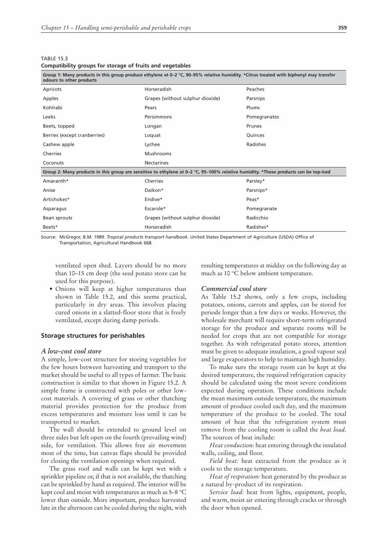
359Chapter 15 – Handling semi-perishable and perishable crops
ventilated open shed. Layers should be no more than 10–15 cm deep (the seed potato store can be used for this purpose).
• Onions will keep at higher temperatures than shown in Table 15.2, and this seems practical, particularly in dry areas. This involves placing cured onions in a slatted-floor store that is freely ventilated, except during damp periods.
Storage structures for perishables
A low-cost cool storeA simple, low-cost structure for storing vegetables for the few hours between harvesting and transport to the market should be useful to all types of farmer. The basic construction is similar to that shown in Figure 15.2. A simple frame is constructed with poles or other low-cost materials. A covering of grass or other thatching material provides protection for the produce from excess temperatures and moisture loss until it can be transported to market.
The wall should be extended to ground level on three sides but left open on the fourth (prevailing wind) side, for ventilation. This allows free air movement most of the time, but canvas flaps should be provided for closing the ventilation openings when required.
The grass roof and walls can be kept wet with a sprinkler pipeline or, if that is not available, the thatching can be sprinkled by hand as required. The interior will be kept cool and moist with temperatures as much as 5–8 °C lower than outside. More important, produce harvested late in the afternoon can be cooled during the night, with
resulting temperatures at midday on the following day as much as 10 °C below ambient temperature.
Commercial cool storeAs Table 15.2 shows, only a few crops, including potatoes, onions, carrots and apples, can be stored for periods longer than a few days or weeks. However, the wholesale merchant will require short-term refrigerated storage for the produce and separate rooms will be needed for crops that are not compatible for storage together. As with refrigerated potato stores, attention must be given to adequate insulation, a good vapour seal and large evaporators to help to maintain high humidity.
To make sure the storage room can be kept at the desired temperature, the required refrigeration capacity should be calculated using the most severe conditions expected during operation. These conditions include the mean maximum outside temperature, the maximum amount of produce cooled each day, and the maximum temperature of the produce to be cooled. The total amount of heat that the refrigeration system must remove from the cooling room is called the heat load. The sources of heat include:
Heat conduction: heat entering through the insulated walls, ceiling, and floor.
Field heat: heat extracted from the produce as it cools to the storage temperature.
Heat of respiration: heat generated by the produce as a natural by-product of its respiration.
Service load: heat from lights, equipment, people, and warm, moist air entering through cracks or through the door when opened.
Table 15.3compatibility groups for storage of fruits and vegetables
Group 1: many products in this group produce ethylene at 0–2 °c, 90–95% relative humidity. *citrus treated with biphenyl may transfer odours to other products
apricots Horseradish Peaches
apples Grapes (without sulphur dioxide) Parsnips
Kohlrabi Pears Plums
leeks Persimmons Pomegranates
beets, topped longan Prunes
berries (except cranberries) loquat Quinces
Cashew apple lychee Radishes
Cherries Mushrooms
Coconuts Nectarines
Group 2: many products in this group are sensitive to ethylene at 0–2 °c, 95–100% relative humidity. *These products can be top-iced
amaranth* Cherries Parsley*
anise Daikon* Parsnips*
artichokes* endive* Peas*
asparagus escarole* Pomegranate
bean sprouts Grapes (without sulphur dioxide) Radicchio
beets* Horseradish Radishes*
Source: McGregor, b.M. 1989. Tropical products transport handbook. United States Department of agriculture (USDa) Office of Transportation, agricultural Handbook 668.

360 Rural structures in the tropics: design and development
common cooling methods for produceCooling methods include the following:
Room cooling: This involves placing produce in an insulated room equipped with refrigeration units to chill the air. Although room cooling is effective for storing precooled produce, in some cases it cannot remove field heat rapidly enough. Carefully directing the output of the cooling system evaporator fans can improve the cooling rate significantly.
Forced-air cooling: This is used in conjunction with a cooling room and is effective on most packaged produce. To increase the cooling rate, additional fans are used to increase the flow of cool air through the packages of produce. Although the cooling rate depends on the air temperature and the rate of airflow through the packages, this method is usually 75–90 percent faster than room cooling. The fans are normally equipped with a thermostat that automatically shuts them off as soon as the desired produce temperature is reached, to reduce energy consumption and water loss from the produce.
Hydro-cooling: This method can be used on most commodities that are not sensitive to wetting. Wetting often encourages the growth of microorganisms. In this process, chilled water flows over the produce, rapidly removing heat. At typical flow rates and temperature differences, water removes heat about 15 times faster than air. However, hydro-cooling is only about 20–40 percent energy efficient, compared with 70–80 percent for room cooling and forced-air cooling.
Top or liquid icing: This may be used on a variety of commodities. In the top-icing process, crushed ice is added to the container on top of the produce by hand or machine. For liquid icing, aslurry of water and ice is injected into produce packages through vents or handholds without de-palletizing the packages or removing their tops. As the ice has a residual effect, this method works well with commodities, such as sweet-corn and broccoli, that have a high respiration rate. One kilogram of ice will cool about 3 kg of produce from 29 °C to 4 °C.
Vacuum cooling: This system is effective on products that have a high ratio of surface area to volume, such as leafy greens and lettuce, which would be very difficult to cool with forced-air or hydro-cooling. The produce is placed inside a large metal cylinder and much of the air is evacuated. The vacuum causes water to evaporate rapidly from the surface of the produce, lowering its temperature. If overdone, this process may cause wilting from water loss. Vacuum coolers can be energy efficient but are expensive to purchase and operate.
Evaporative cooling: This is an effective and inexpensive means of providing a lower temperature atmosphere with high relative humidity for cooling produce. It is accomplished by misting or wetting the produce in the presence of a stream of dry air. Evaporative cooling works best when the relative humidity of the air is below 65 percent.
Transportation of horticultural cropsTransport vehicles should be well insulated to maintain cool environments for precooled commodities and well ventilated to allow air movement through the produce. Travelling during the night and early morning can reduce the heat load on vehicles transporting produce. Mixed loads can be a serious concern when optimum temperatures are not compatible or when ethylene-producing commodities and ethylene-sensitive commodities are transported together.
A wide range of pallet covers are available for covering cooled products during handling and transportation. Polyethylene covers are inexpensive and lightweight and they protect pallet loads from dust, moisture and some loss of cold. Lightweight insulated covers can protect the load from heat gain for several hours. Heavyweight covers are sometimes used to protect tropical products from the cold during winter shipment.
refrigerated trailersFor optimum transport temperature management, refrigerated trailers need insulation, a high-capacity refrigeration unit and fan, and an air delivery duct. The condition of the inside of a refrigerated trailer affects its ability to maintain desired temperatures during transportation. Handlers should inspect the trailer before loading and check the following:
• door and door seal damage• wall damage• clean floor• floor drains clean and open• door and inside height adequate for the intended
load• trailer precooled before loading• refrigeration unit operates satisfactorily.
open vehiclesAn open-air vehicle can be loaded in such a way as to allow air to pass through the load, and to provide some cooling of the produce as the vehicle moves. Bulk loads of produce should be carefully loaded to avoid causing mechanical damage. Vehicles can be padded or lined with a thick layer of straw. Woven mats or sacks can be used in the beds of small vehicles. Other loads should not be placed on top of the bulk commodity. High transportation speeds and/or long-distance transport run the risk of causing excess drying of the crop.

361Chapter 15 – Handling semi-perishable and perishable crops
reView queSTioNS1. Describe the operational principle of a
refrigeration system.2. Describe some of the ways in which some
semiperishable and perishable crops are stored in your locality, and identify the advantages and disadvantages of such storage systems.
3. Discuss the different crop-cooling methods for produce while in storage.
4. Outline in detail the steps involved in determining the refrigeration load required for a cold-storage facility.
FurTHer reaDiNGBooth, R.H. & Shaw, R.L. 1981. Principles of potato
storage, Lima, International Potato Centre.Farm Electric Centre. 1974. Vegetable storage: a guide
to the practical design of installations. Warwickshire, National Agriculture Centre.
FAO. 1970. Sundrying fruits and vegetables. FAO Agricultural Services Bulletin No. 5. Rome.
FAO. 1972. Fruit juice processing. FAO Agricultural Services Bulletin No. 13. Rome.
FAO. 1973. Cold-storage design and operation: fruit juice processing. FAO Agricultural Services Bulletin No. 19. Rome.
FAO. 1977. Cassava Processing, 2nd ed. FAO Agricultural Services Bulletin No. 8. Rome.
FAO. 1980. Food loss prevention in perishable crops. FAO Agricultural Services Bulletin No. 43. Rome.
Golob, P., Farrell, G. & Orchard, J.E. 2002. Crop post-harvest: science and technology. Volume 1. Oxford, United Kingdom, Blackwell Science Ltd.
Graf Ballestrem, C. & Holler, H.J. 1977. Potato production in Kenya: experiences and recommendations for improvements. Eschborn, German Agency for Technical Cooperation, Ltd. (GTZ).
Kasmire, R.F. & Hinsch, R.T. 1987. Maintaining optimum transit temperatures in refrigerated truck shipments of perishables. University of California Perishables Handling Transportation Supplement No. 2.
McGregor, B.M. 1989. Tropical products transport handbook. Agricultural Handbook No. 668. United States Department of Agriculture (USDA), Office of Transportation.
McLean, K.A. 1980. Handling and storage of combinable crops. Ipswich, Farming Press Ltd.
Plucknett, D.L. (ed.). 1979. Small-scale processing and storage of tropical root crops. Westview Tropical Agricultural Series No. 1. Boulder, Colorado, Westview Press Inc.
Willis, R.H.H., Lee, T.H., Graham D., McGlasson, W.B. & Hall, E.G. 1981. Postharvest: an introduction to the physiology and handling of fruit and vegetables. London, Granada Publishing Ltd.
World Food Programme (WFP). 1979. Food storage: handbook on good storage practice. Rome.