chapter 13 dsp-based vector control of induction motors...
TRANSCRIPT

Chapter 13
DSP-BASED VECTOR CONTROL OF INDUCTION MOTORS
13.1 Introduction
For many years, induction motors have been preferred for a variety of industrialapplications because of their robust and rugged construction. Until a few years ago,the induction motor could either be plugged directly into the grid (uncontrolled) orcontrolled by means of the well-known scalar volts per Hertz (V/f) method. Invariable speed drives, both methods have serious drawbacks in the areas ofefficiency, reliability, and electromagnetic interference (EMI). With theuncontrolled method, even a simple change in the reference speed is not possible.Additionally, its system integration depends highly on the motor design (i.e.,starting torque vs. maximum torque, torque vs. inertia, number of pole pairs, etc).
The scalar V/f method is able to provide speed variation, but this methodcannot provide real-time control. In other words, the system response is only satisfactory at steady state and not during transient conditions. This results inexcessive current and over-heating, which necessitate the drive to be oversized.This over-design no longer makes the motor cost effective due to the high cost ofthe drive circuitry. By using real-time processors such as the LF2407 DSP controller, and with an accurate induction motor model, the development of highlyreliable and accurate variable speed motor drives becomes possible.
With the advent of field-oriented control (FOC) schemes, induction motors can be made to operate similar to separately excited dc motors. The indirect field oriented controls, or vector control, for speed and torque controlled AC drives arebecoming the industry standard in order to obtain high dynamic motor performance.
The control algorithm explained in this chapter is a rotor flux field-orientatedcontrol strategy. In this chapter, we will go through not only the implementation ofthe control software, but also the theoretical and practical aspects of the vector control. In the end, the reader will be familiar with the different parts of the FOC strategy of the induction motor as well as the developmental steps involved. Thereader should also be able to apply this induction motor drive solution to otherdesired systems. This chapter deals with the structure of an induction motor and develops its model followed by its FOC schemes. Finally, hardware and softwaredevelopment procedures covered.
13.2 Three-Phase Induction Motor Basic Theory
13.2.1 Three-Phase Induction Motor
Three-phase induction machines are asynchronous machines that operate belowthe synchronous speed when motoring and above the synchronous speed whengenerating. They are the most popular machine used in industry today and are
255
Copyright © 2004 CRC Press, LLC

DSP-Based Vector Control of Induction Motors256
rugged and require very little maintenance. Compared to dc motors, inductionmotors are not as easy to control. They typically draw large starting currents, aboutsix to eight times their full load values, and operate with lagging power factor whenloaded. However, with the advent of the vector control concept for motor control, itis possible to decouple the torque and the flux, thus making the control of theinduction motor very similar to that of the dc motor.
13.2.2 Induction Motor Construction
The dc motor can be called a conduction motor because the electric power isconducted directly to the armature through the brushes and commutator. In the caseof induction motors, the rotor receives power by induction; the same way asecondary of a two-winding transformer receives power from the primary. This is why the induction motor can be treated as a rotating transformer, where the primarywinding is stationary, but the secondary is free to rotate. We use this concept todevelop the equivalent circuit for induction motors.
The most popular type of induction motor used is the squirrel cage inductionmotor shown in Fig. 13.1. The rotor consists of a laminated core with parallel slotsfor carrying the rotor conductors, which are usually heavy bars of copper,aluminum, or alloys. One bar is placed in each slot; or rather, the bars are insertedfrom the end when the semi-closed slots are used. The rotor bars are brazed,electrically welded, or bolted to two heavy and stout short-circuiting end-rings, thuscompleting the squirrel cage construction. The rotor bars are permanently short-circuited on themselves. The rotor slots are usually not parallel to the shaft, but are given a slight angle, called a skew, which increases the rotor resistance due to increased length of rotor bars and an increase in the slip for a given torque. Theskew is also advantageous because it reduces the magnetic hum while the motor isoperating and reduces the locking tendency, or cogging, of the rotor teeth.
Figure 13.1 Short-circuited rotor bars of the squirrel cage induction motor.
Copyright © 2004 CRC Press, LLC
DSP-Based Vector Control of Induction Motors 257
13.2.3 Operation
When the three-phase stator windings are fed by a three-phase supply, a magnetic flux of a constant magnitude rotating at synchronous speed is createdinside the motor. Due to the relative speed between the rotating flux and thestationary conductors, an electromagnetic force (EMF) is induced in the rotor in accordance with Faraday’s laws of electromagnetic induction. The frequency of theinduced EMF is the same as the supply frequency, and the magnitude is proportional to the relative velocity between the flux and the conductors. Thedirection of this EMF is given by Fleming’s right-hand rule. Since the rotor barsform a closed path as shown in Fig. 13.1, a rotor current is produced which,according to Lenz’s law, is opposite to that of the relative velocity between therotating flux and the conductors. Therefore, the rotor current develops in the samedirection as the flux and tries to catch up with the rotating flux.
13.2.4 Slip
The difference between the synchronous speed e and the actual speed r ofthe motor is called the slip.
e
res (13.1)
13.3 Model of the Three-Phase Induction Motor in Simulink
13.3.1 Voltage Equations of the Idealized Motor Model
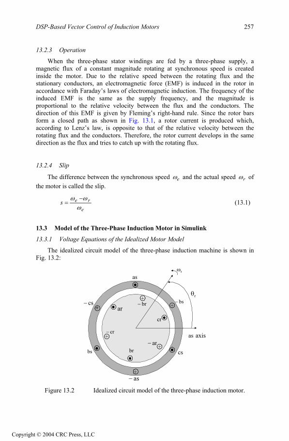
The idealized circuit model of the three-phase induction machine is shown inFig. 13.2:
r
r
as
bs cs
as
brar
cr
bscsar
br
cr
as axis
Figure 13.2 Idealized circuit model of the three-phase induction motor.
Copyright © 2004 CRC Press, LLC

DSP-Based Vector Control of Induction Motors258
Stator voltage equations:
t
asassas d
dirv (13.2)
t
bsbssbs d
dirv (13.3)
t
cscsscs d
dirv (13.4)
Rotor voltage equations:
t
arrarar d
driv ' (13.5)
t
brrbrbr d
driv ' (13.6)
t
crrcrcr d
driv ' (13.7)
Flux linkage equations:
(13.8)abcr
abcs
abcrr
abcrs
abcsr
abcss
abcr
abcs
i
i
LL
LL
where:
, , , i (13.9)
cs
bs
asabcs
cr
br
arabcr
cs
bs
asabcs
iii
i
cr
br
arabcr
iii
The stator-to-stator and rotor-to-rotor winding inductances are:
,
sslssmsm
smsslssm
smsmsslsabcss
LLLLLLLLLLLL
L
(13.10)
rrlrrmrm
rmrrlrrm
rmrmrrlrabcrr
LLLLLLLLLLLL
L
The stator-to-rotor mutual inductances are dependent on the rotor angle:
rrr
rrr
rrr
srTabc
rsabcsr LLL
cos)32cos()32cos()32cos(cos)32cos()32cos()32cos(cos
(13.11)
where:
Copyright © 2004 CRC Press, LLC

DSP-Based Vector Control of Induction Motors 259
= Stator winding leakage inductance per phasesL = Self inductance of stator windingssL = Peak value of stator to rotor mutual inductance smL
= Peak value of stator to rotor mutual inductance srLIf
Pg = air-gap permeance,then
, , ,gsss PNL 2grssr PNNL )3/2(2 CosPNL gssm
, (13.12))3/2(2 CosPNL grrm grrr PNL 2
We can see that the idealized machine is described by six first-order differentialequations; one for each winding. These differential equations are coupled to oneanother by the mutual inductances between the windings. The stator-to-rotor coupling terms are a function of the rotor position, so when the rotor rotates, thecoupling terms change with time. To solve this problem, induction motor equationsare transferred to the quadrature rotating reference frame such that the mutualinductances are not time dependent.
13.4 Reference Frame Theory
Reference frame theory is an integral part of electric drives. Reference framesare powerful tools for the analysis and application of sophisticated controltechniques, particularly in the case of the three-phase induction and synchronousmachines. Using reference frame theory, it is possible to transform the machinephase variables to another reference frame. By judicious choice of the referenceframes, it is possible to considerably reduce the complexity of the model machine.Reference frame theory has become especially important for digital motor controlwhere the need for accurate but simple motor models is essential. Though the theorycan be extended to any arbitrary reference frame, the two most commonly usedreference frames are the Stationary Reference Frame and the SynchronousReference Frame. The Clarke and Park transformations are used to transfer theinduction motor equations to these frames. The transformations are discussed in Chapter 10 in detail and are repeated here for reference. Clarke’s transformation is given by
(13.12)
cs
bs
as
ss
sds
sqs
fff
T
f
f
f
)0(
0
where
Copyright © 2004 CRC Press, LLC

DSP-Based Vector Control of Induction Motors260
2/12/12/12/32/302/12/11
3/2)0(T (13.13)
Park’s Transformation is represented by
(13.14)s
ds
sqs
eds
eqs
ff
f
fcossinsincos
where the rotor position is given by
(13.15)dte
13.5 Induction Motor Model in the Arbitrary q-d-0 Reference Frame
As mentioned previously, the two most common reference frames chosen torepresent the induction motor are the stationary and the synchronous referenceframes. The stationary reference frame has the q-d-0 variables of the machine in thesame frame as those normally used for the supply network. This choice of networkis usually made when the supply network is large or complex. In the case of thesynchronously rotating reference frame, the q-d-0 variables are constants at steadystate.
Assuming that the induction motor is rotating at speed in the direction ofrotor rotation, the machine equations in the stationary reference frame can be obtained by setting = 0. Likewise, the equations in the synchronous referenceframe are obtained by setting = e. Applying transformation to the stator windings a-b-c voltages, the stator winding q-d-0 voltages in the arbitrary referenceframe are obtained.
(13.16)sqds
sqd
sqd
sqd irpv 0000
000001010
where dtdp . Applying the transformation to the rotor voltage equation, we get
(13.17)rqdr
rqd
rqdr
rqd irpv 0000
000001010
)(
Stator and rotor flux linkage equations are given by
Copyright © 2004 CRC Press, LLC

DSP-Based Vector Control of Induction Motors 261
(13.18)
'0
'
'0
'
'
'
'0
'
'0
00000
0
00
0
00
000
0
0
00
000000
00
r
dr
qr
s
ds
qs
lr
mlr
m
mlr
m
m
ls
mls
mmls
r
dr
qr
s
ds
qs
i
i
iiii
LLL
L
LLL
LL
LLLLL
where the primed values are referred values to the stator side according to thefollowing relationships:
qrr
sqr N
N' (13.19)
drr
sdr N
N' (13.20)
qrr
sqr i
NNi ' (13.21)
drr
sdr i
NNi ' (13.22)
lrr
slr LNNL
2' (13.23)
Magnetizing inductance on the stator side is given by
rrr
ssr
r
sssm L
NN
LNN
LL23
23
23 (13.24)
The electromagnetic torque equation is given by
))(()(22
3 ''''drqrqrdrrdsqsqsds
rem iiiiPT
dsqrqsdrm
dsqsqsds
qrdrdrqr
iiiiLP
iiP
iiP
''
''''
223
223
223
(13.25)
13.6 Field Oriented Control
The term “vector” control refers to the control technique that controls both the amplitude and the phase of ac excitation voltage. Vector control therefore controlsthe spatial orientation of the electromagnetic fields in the machine. This has led to the coining of the term field oriented control (FOC), which is used for controllers
Copyright © 2004 CRC Press, LLC

DSP-Based Vector Control of Induction Motors262
that maintain a 90 spatial orientation between the critical field components. Theterm “field angle control” refers to the control strategy where the system is not at 90 of spatial orientation. In order to properly comprehend vector control, we mustunderstand the principle of dc machine torque control on which FOC is based.
13.7 DC Machine Torque Control
The required 90 of spatial orientation between key field components can be compared to the dc motor, where the armature winding magnetic field and the filed winding magnetic filed are always in quadrature. The objective is to force thecontrol of the induction machine to be similar to the control of a dc motor, i.e.,torque control. In dc machines, the field and the armature winding axes areorthogonal to one another, making the MMFs established orthogonal. If the ironsaturation is ignored, then the orthogonal fields can be considered to be completelydecoupled.
For dc machines, the developed torque is
(13.26)afaem IIKT )(where
= Constantak= Field flux)( fI
= Armature currentaISince the torque angle is always 90 , the flux and the torque can be controlled
independently. The torque is controlled by adjusting the field current If, and the fluxis directly controlled by adjusting the armature current Ia.
It is important to maintain a constant field flux for good torque control. It isalso important to maintain an independently controlled armature current in order toovercome the effects of the resistance of the armature winding, leakage inductance,and the induced voltage is needed. A spatial angle of 90 between the flux andMMF axes has to be maintained in order to limit interaction between the MMF andthe flux. If these conditions are met at every instant of time, the torque will always follow the current. In the case of dc machines, there is constant field flux and 90torque angle due to the commutator and the separate field excitation system. In ac machines, these conditions have to be attained by using external controls, makingthe system more complex and difficult to understand.
13.8 Field Oriented Control, Direct and Indirect Approaches
With vector control, the mechanically robust induction motors can be used in high performance applications where dc motors were previously used. The keyfeature of the control scheme is the orientation of the synchronously rotating q-d-0frame to the rotor flux vector. The d-axis component is aligned with the rotor flux
Copyright © 2004 CRC Press, LLC

DSP-Based Vector Control of Induction Motors 263
vector and regarded as the flux-producing current component. On the other hand,the q-axis current, which is perpendicular to the d-axis, is solely responsible fortorque production.
In order to apply a rotor flux field orientation condition, the rotor flux linkage is
aligned with the d-axis so and . By manipulating (13.16) and
(13.17) in the rotating reference frame,
0eqr r
edr ˆ
r , we can obtain the field orientedcondition.
mL
edre
dsistatesteadyedsimL
rLrre
drrLrre
drp 0 (13.27)
rr
eqsimLe
qs)irLmL
(r
rrslip ˆ (13.28)
eqsid
rLmLP
eT
eqsi
lrLmLmLe
qri
ˆ22
3(13.29)
We can find out that in this case i controls the rotor flux linkage and
controls the electromagnetic torque. The reference currents of the q-d-0 axis
are converted to the reference phase voltages (v as the
commanded voltages for the control loop. Given the position of the rotor flux andtwo-phase currents, this generic algorithm implements the instantaneous directtorque and flux control by means of coordinate transformations and PI regulators,thereby achieving accurate and efficient motor control.
eds
eqsi
e*qs(i )e*
ds,i )e*qs,ve*
ds
In asynchronous drives, the mechanical rotor angular speed is not, bydefinition, equal to the rotor flux angular speed. This implies that the necessaryrotor flux position cannot be detected directly by the mechanical position sensor provided with the asynchronous motor explained here.
It is clear that for implementing vector control we have to determine the rotorflux position. Two basic approaches to determine the rotor flux position angle have evolved. The direct scheme shown in Fig. 13.3(a), electrically determines the rotor flux position from measurements using field angle sensors. The indirect schemeillustrated in Fig. 13.3(b), measures the rotor position and utilizes the slip relation to compute the angle of the rotor flux relative to the rotor axis. From the feasibility point of view, implementation of the direct method is difficult if not sometimesimpossible. Therefore, in this chapter, the indirect method is considered as a solution for implementing FOC.
Copyright © 2004 CRC Press, LLC

DSP-Based Vector Control of Induction Motors264
FieldOriented
ControllerInverter
FluxCompensator
FS
IM
Te*
lqdr*
iabcs
FluxSensor
InductionMotor
lqdr
lqdm
(a) Direct flux sensing method.
FieldOriented
ControllerInverter
FluxCalculator
IM InductionMotor
PG SpeedSensor
w r
lqdr
Te*
lqdr*
iabcs
(b) Indirect flux sensing method.
Figure 13.3 Two generic types of induction motor vector control.
The indirect method is based on the calculation of the slip speed ,required for correct field orientation. Equations (13.27) and (13.28) show that wecan control torque and field by and i in the excitation frame. However, in the
implementation of field-oriented control, we need to know i and in the stationary reference frame. So, we have to know the angular position of the rotorflux to transform and i from the excitation frame to the stationary frame. By
using , which is shown in (13.28) and using actual rotor speed, the rotor flux position is obtained.
slip
dsi qs
ds qsi
dsi qs
slip
(13.30)(t)dtdt rt
ret
slip00
or
(13.31)(t)(t)dt rret
slip0
In literature, the algorithm of finding rotor flux position using the calculated and measured or is called the Current Model Method. The Current
Model takes and as inputs as well as the rotor mechanical speed and givesslip re
qsire
dsi
Copyright © 2004 CRC Press, LLC

DSP-Based Vector Control of Induction Motors 265
the rotor flux position as an output. Figure 13.4 shows the block diagram of the vector control strategy in which speed regulation is possible using a control loop.
The absence of the field angle sensors, along with the ease of operation at low speeds, has increased the popularity of the indirect vector control strategy. Whilethe direct method is inherently the most desirable scheme, it suffers from the unreliability in measuring the flux. Although the indirect method can approach the performance of the direct measurement scheme, its major weakness is the accuracy of the control gain, which heavily depends on the motor parameters.
FluxController
PI PI
PI
SVPWM
3-phaseInverter
Induction
motor
abc
CurrentModel
- i -
-
Vdc
ClarkeTransformation
ParkTransformation
Inv. ParkTransformation
r
+ +
+
Mechanical Speed of rotor
dse*
iqse* v qs
e*
v dse*
v qss*
v dss*
idss
iqss
idse
iqse
dqss
dqse
dq se
dqss
dqss
ref
rm
Figure 13.4 Vector control scheme for induction motor.
As shown in Fig. 13.4, two-phase current feeds the Clarke transformationblock. These projection outputs are indicated as i and . These twocomponents of the current provide the inputs to Park’s transformation, which givesthe currents in the excitation reference frame. The and i components,which are outputs of the Park transformation block, are compared to their referencevalues , the flux reference, and , the torque reference. The torque command,
, comes from the output of the speed controller. The flux command, i , is theoutput of the flux controller which indicates the right rotor flux command for everyspeed reference. For i we can use the fact that the magnetizing current is usuallybetween 40 and 60% of the nominal current. For operating in speeds above thenominal speed, a field weakening section should be used in the flux controller
sds
i
sqsi
eqs
eqds
e*ds
eds
e*dsi e*
qsie*qsi e*
ds
Copyright © 2004 CRC Press, LLC
DSP-Based Vector Control of Induction Motors266
section. The current regulator outputs, and , are applied to the inverse Park
transformation. The outputs of this projection are and v , which are the
components of the stator voltage vector in the orthogonal reference frame.They form the inputs of the SVPWM block. The outputs of this block are the signalsthat drive the inverter.
e*dsv e*
qsv
dqs
sds
sdsv
s
sqs
Note that both the Park and the inverse Park transformations require the exactrotor flux position, which is given by the current model block. This block needs therotor resistance or rotor time constant as a parameter. Accurate knowledge of therotor resistance is essential to achieve the highest possible efficiency from thecontrol structure. Lack of this knowledge results in the detuning of the FOC. InFig. 13.4, a SVPWM has been used to emulate v and in order to implementcurrent regulation. The reader can find more information about SVPWM in Chapter11.
sqsv
13.9 Simulation Results for the Induction Motor Control System
The drive system with the proposed control strategy has been simulated prior tolaboratory experimentation. For simulation purposes, software packages such asMatlab/SimulinkTM and Advanced Continuous Simulation Language (ACSL)TM can be used. In this section, SimulinkTM has been used to model the induction motor,the vector control, and the SVPWM. The induction motor has been simulated with the dynamic q-d-0 model using the nominal parameters as given in Table 13.1. Thedc link voltage in the simulation is equal to 100V. Maximum phase current hasbeen limited to the rated value. Initially, the magnetizing current is set at 60% of the rated current. The simulation results of the control system to a command speed areshown in Fig. 13.5.
13.10 Induction Motor Speed Control System
Based on the previous analysis, an induction motor speed control system is developed as shown in Fig. 13.6. The total control system consists of the inductionmotor, the power electronics converter, the sensor, and the controller. Thesecomponents are discussed in detail in the following section.
Copyright © 2004 CRC Press, LLC

DSP-Based Vector Control of Induction Motors 267
0 1 2-150
0
150
(a)
0 1 2-150
0
150
(b)
0 1 2-5
5
15
(c)
0 1 2-20
0
20
(d)
0 1 240
50
60
(e)
0 1 2-5
5
15
(f)
0 1 2-75
0
75
(g)
Time (sec.)
Figure 13.5 (a) reference speed, (b) actual speed, (c) load torque, (d)electromagnetic torque, (e) stator d-axis current in the rotating reference frame, (f)
stator q-axis current in the rotating reference frame, (g) phase-A current.
Controller
D1
D2D4
D3C
T1
T2
T3
T4
T5
T6
Vs
to T1~T6
IM
ias
ibs
Encoder
QEP-A
QEP-B
Figure 13.6 Induction motor speed control system.
Copyright © 2004 CRC Press, LLC

DSP-Based Vector Control of Induction Motors268
13.11 System Components
13.11.1 Power Electronic Converter
As shown in Fig. 13.9, the power electronics converter in induction motorcontrol system consists of two parts: a front-end rectifier and a three-phase full-bridge inverter in the right-hand side. The rectifier usually is a full-bridge diode. Incase of a regenerative system, a power switch rectifier is used.
The inverter is usually responsible for both the electronic commutation andcurrent regulation. Pulse-width-modulated current controllers are typically used toregulate the actual machine currents to match the sinusoidal current referencewaveforms.
The power hardware used to implement and test the induction motor drivesystem can support an input voltage of 1200 V and a maximum current of 50 A. Thehardware is based on six power IGBTs (SKM 50GB 123D), driven by the DSP controller via the integrated driver SKHI22. The power and the control componentsare insolated from one another by the use of opto-couplers in the gate drive signalpath.
Table 13.1 Induction motor parameters
Motor Parameters ValueRated power 3.0 hpRated Voltage 230/460 VoltRated Current 7.6/3.8 AmpRated Speed 1760 rpmPole pairs 2Rated frequency 60 Hz Nominal efficiency 87.5%Base impedance 23.64631Stator resistance 0.044225Magnetizing impedance 1.1178Stator leakage impedance 0.05956Rotor leakage impedance 0.05956Rotor resistance 0.03078
13.11.2 Sensors
Two types of sensors for the induction motor control system are used. One is acurrent sensor and the other is a position sensor. The phase current sensing is performed via two current sensors supplied with 15 V. Their maximum inputcurrents can be changed by the number of turns in the primary winding, and theoutput is a bipolar voltage.
Copyright © 2004 CRC Press, LLC

DSP-Based Vector Control of Induction Motors 269
Encoders or resolvers serve as the position sensor because every point of therotor position is needed to synchronize the rotor with the stator excitation. Figure13.7 shows the structure of an optical encoder. It consists of a light source, aradially slotted disk and photoelectric sensors. The disk rotates with the rotor. The two photo sensors detect the light passing through the slots in the disk. When the light is hidden, a logic “0” is generated by the sensors. When the light passesthrough the slots of the disk, a logic “1” is produced. These logic signals are shown in Fig. 13.7. By counting the number of pulses, the motor speed can be calculated.The direction of rotation can be determined by detecting the leading signal between signal A and signal B.
AB
LightSensors A
B
Figure 13.7 The structure of an encoder.
13.11.3 Controller
The controller of the induction motor control system is used to read thefeedback current and position signals, to implement the speed or torque control algorithm, and to generate the gate signals based on the control signal. Analogcontrollers or digital signal processors can perform this task. We have used theLF2407 as a controller.
The interface of the LF2407 is illustrated in Fig. 13.8. Two quadraturecounters detect the rising and falling edges of the encoder signals. Two inputchannels related to the 10-bit Analog-to-Digital Converter (ADC) are selected to read the two-phase currents. The pins PWM1 to PWM6 output the gating signals tothe gate drive circuitry.
Copyright © 2004 CRC Press, LLC

DSP-Based Vector Control of Induction Motors270
Q EP-1
Q EP-2
PW M -1 & PW M -6G ateD rive
T M S320F2407
En A
AD CIN -1
AD CIN -0Ia
Ib
En B
Figure 13.8 The interface of LF2407.
13.12 Implementation of Field-Oriented Speed Control of Induction Motor
Some practical aspects of implementing the block diagram of Fig. 13.8 arediscussed in this section and subsections. The software organization, the utilizationof different variables, and the handling of the DSP controller resources aredescribed. In addition, the control structure for the per-unit model is presented.Next, some numerical considerations have been made in order to address theproblems inherent within fixed-point calculation. As described, current model is one of the most important blocks in the block diagram depicted in Fig. 13.4. Theinputs of this block are the currents and mechanical speed of rotor. Two sections ofthis chapter deal with technical points that should be considered during current andspeed measurement, as well as their scaling. Also, there are some points to be notedduring development of the current model in software; therefore, one section isdedicated to current model implementation. A PI controller is used in the field-oriented speed control of the induction motor as a regulator for current and speedcontrol. The PI structure and block diagram are presented in another section.
13.12.1 Software Organization
The body of the software consists of two main modules: the initialization module and the PWM Interrupt Service Routine (ISR) module. The initialization model is executed only once at startup. The PWM ISR module interrupts the waiting infinite loop when the timer underflows. When the underflow interrupt flagis set, the corresponding ISR is served. Figure 13.9 shows the general structure ofthe software. The complete FOC algorithm is executed within the PWM ISR so thatit runs at the same frequency as the switching frequency or at a fraction of it. The wait loop could be easily replaced with a user interface [1].
Copyright © 2004 CRC Press, LLC

DSP-Based Vector Control of Induction Motors 271
HardwareInitialization
Start
VariableInitialization
Inf. Loop PWMI.S.R
Figure 13.9 General structure of software.
13.12.2 Base Values and Per-Unit Model
It is often convenient to express machine parameters and variables of per-unitquantities. Moreover, the LF2407 is a fixed point DSP, so using a normalized per-unit model of the induction motor is easier than using real parameters. In thismodel, all quantities refer to the base values. Base power and base voltage are selected, and all parameters and variables are normalized using these basequantities. Although one might violate this convention from time to time when dealing with instantaneous quantities, the rms values of the rated phase voltage and current are generally selected as the base voltage for the a-b-c variables while the peak value is generally selected as the base voltage for d-q variables. The basevalues are determined from the nominal values by using (13.31), where , V ,are the nominal phase current, the nominal phase to neutral voltage, and the nominalfrequency in a star-connected induction motor, respectively. The base valuedefinitions are as follows:
nI n nf
b
bb
nb
nb
nb
VfVV
II
22
2
(13.31)
bI and V are the maximum values of the nominal phase current and voltage,is the electrical nominal rotor flux speed, and is the base flux.
b b
b
Copyright © 2004 CRC Press, LLC

DSP-Based Vector Control of Induction Motors272
13.12.3 Numerical Considerations
The per-unit model has been developed so that the software representation of speed, current, and flux is equal to 1.0 when the motor has reached its nominalspeed under nominal load and magnetizing current. During transients, the currentmight reach higher values than the nominal current in order to achieve a short response time. Also, the motor speed might exceed the nominal speed ( ), and then every per-unit value might be greater than 1.0. This fact necessitates foreseeingthese situations and determines the most suitable numerical format used for thesoftware.
bI
b
13.12.4 The Numerical Format Determination
The numerical format used in the major part of this chapter is as follows: four bits are dedicated to the integer part, and twelve bits are dedicated to the fractionalpart. This numeric format is denoted by Q4.12. The resolution for this format isgiven by
00024414.02112
With the sign extension mode of the LF2407 set, the link between the real quantity and its Q4.12 format representation is illustrated in Fig. 13.10.
24.4e-5
32767
-32767
-8
7.99975586
Figure 13.10 Representation of Q4.12 format.
The reason for this particular format is that the drive control quantities are, for the most part, not usually greater than four times their nominal values. In otherwords, not greater than four when the per-unit model is considered. Where this is not the case, a different format will be chosen. The selection of a range of [-8,8]ensures that the software values can handle each drive control quantity, not onlyduring steady state operation but also during transient operation.
Copyright © 2004 CRC Press, LLC

DSP-Based Vector Control of Induction Motors 273
The Qx.y numeric format uses x bits for the integer part and y bits for thefractional part, so the resolution is . If z is the per-unit value to implement, then its software value is
y2yz 2 in Qx.y format. Care must be taken when performing
operations with a generic Qx.y format. Adding two Qx.y formatted numbers mayresult in numerical representation overflow. To avoid this kind of problem, one possible solution is to perform the addition in the high side of the Accumulator and set the saturation bit. Another option is to assume that the result will not be out of the maximum range.
The second solution can be used in this implementation if we know that the control quantities do not exceed half of the maximum value in the Q4.12 format.The result can still be represented in the Q4.12 format and directly considered as Q4.12 format, thereby allowing for a higher level of precision. As far as themultiplication is concerned, the result (in the 32-bit Accumulator) must either beshifted x positions to the left and the least significant word stored or be shifted ypositions to the right with the last significant word being stored. The stored result is in Qx.y format. Figure 13.11 shows two Qx.y formatted 16-bit variables that aremultiplied by one another.
The result of this multiplication in Qx.y format is represented in gray in the 32-bit Accumulator. Both solutions are depicted in Fig. 13.11.
yx
yx
MSB LSB MSB LSB
yx
*
yx
yx
High Word Low Word
1
2
Figure 13.11 (1) Left shift and store high accumulator, (2) Right shift and store
low accumulator.
Note that in this section there are also constants that cannot be represented bythe Q4.12 format. Operations requiring different formats follow exactly the sameprocess as that explained above.
Copyright © 2004 CRC Press, LLC

DSP-Based Vector Control of Induction Motors274
13.12.5 Current Measurement
The field-oriented control structure requires two-phase current as inputs. Here,current transducers sense these two currents. The current sensor output therefore needs to be rearranged and scaled so that it may be used by the control software inQ4.12 format value. The complete process of acquiring the current is depicted inFig. 13.12.
SignalConditioner A/D
10-bitRange
adjustmentor offset
CurrentGain
Iabc 1023:0
512:
-512
i abc
Figure 13.12 Current measurement block diagram.
The output signal of current transducer can be either positive or negative. This signal must be adjusted by the analog interface into a range of (0,3.3V) to allow the ADC module to read both positive and negative values. Figure 13.13 shows theinside of the signal conditioner.
CT
1.65v offset
To A/D1.65v
:-1.65v
Iabc
Figure 13.13 Current signal conditioner block diagram.
The amplifier gain is chosen such that sensing maxIIabc results in theabsolute value of the amplifier output to be equal to 1.65V. Note thatrepresents the maximum measurable current, which is not necessarily equal to themaximum phase current. This information is useful at the point where currentscaling becomes necessary. The ADC input voltage is now converted into a 10-bitdigital value. The 1.65V analog offset is digitally subtracted from the convertedresult, thereby giving a signed integer value of the sensed current. The result of thisprocess is shown in Fig. 13.14.
maxI
Copyright © 2004 CRC Press, LLC

DSP-Based Vector Control of Induction Motors 275
512
-512
i
max
max
-i SensedCurrent
Prescaled Value
Figure 13.14 Sensed current values before scaling.
Because the variable format is Q4.12, the sensed phase currents must now beexpressed with the per-unit model and then be converted into the Q4.12 format.Notice that the per-unit representation of the current is defined as the ratio betweenthe measured current and the base current, and the maximum current handled by thehardware is represented by the value 512. The per-unit current conversion into theQ4.12 format is achieved by multiplying the sensed current by the followingconstant:
max
5124096
II
Kb
cu (13.32)
In one single calculation, this constant performs not only the per-unit modelingbut also the numerical conversion into Q4.12 format. When nominal current flowsin a motor running at nominal speed, the current sensing and scaling block output is 1000h (equivalent to 1 per-unit).
The reader may change the numerical format by amending the numerator valueand may adapt this constant to its own current sensing range by recalculatingwith its own value. In this control system, maximum measurable current andbase current are = 12A and = 10.7A, respectively. The constant value is:
cuK
maxIImax bI
Q8.8808978
12710512
4096 hF..
Kcu
Note that is outside the Q4.12 format range. The most appropriate formatto accommodate this constant is the Q8.8 format, which has a resolution of
cuK
Copyright © 2004 CRC Press, LLC

DSP-Based Vector Control of Induction Motors276
00390625.0218
and the following correspondence to Fig. 13.15.
39.06e-4
32767
-32767
-128
127.996
Figure 13.15 Representation of Q8.8 format.
The currents of two phases can be sampled by means of the DSP controllerusing two channels of the ADC module. The block of assembly code below readsand scales the current of phase A.
; Reading and scaling current value of phase A LDP #RESULT2>>7LACL RESULT2 ;Reading A/D result register RPT #5 ;Shift to right 6 times SFRAND #0000001111111111bSUB #512 ;Subtracting offset value LDP #IA SACL IA LAR AR0, #KcurLT IA MPY * ;Multiplying by coefficient to scale the ;current valuePACSFLSACH IA,7 ;Save current value in proper variable
13.12.6 Speed Measurement
As previously mentioned, for finding rotor flux position, it is necessary tomeasure the rotor mechanical speed. Usually an incremental encoder is used as aspeed sensor. A 64 pulse per revolution incremental encoder is used to measure themotor speed. The software speed resolution is thus based onincrements per revolution. This sensor has two outputs and produces two pulsetrains that are 90
256644
0 out of phase with respect to each other. The periods of the pulses
Copyright © 2004 CRC Press, LLC

DSP-Based Vector Control of Induction Motors 277
proportionally to the rotor speed. The two output channels A and B of speed sensorcan be wired directly to the QEP input pins of the LF2407.
Because a low count encoder is used in the control system, and because thisencoder does not have enough resolution at low speeds, the control system uses twomethods in order to estimate the induction motor speed. One method has enoughaccuracy in the high speed region, above 200 rpm, and the other has appropriateresolution in the low speed region under 200 rpm. The first method, which is utilized during high speed, is based on counting the number of encoder pulses in a specific time interval. However, the second method is based on the measurement of time between two encoder pulses. Based on the motor speed, the developed programcan utilize the advantages of both methods and switch between the two methodsbased on the actual speed of the motor.
13.12.7 Speed Estimation during High-Speed Region
As previously mentioned, this method is based on counting the number of encoder pulses in a specified time interval. The QEP assigned timer counts the number of pulses and records it in the timer counter register (TxCNT). As themechanical time constant is much slower than the electrical one, the speed regulation loop frequency might be lower than the current loop frequency. Thespeed regulation loop frequency is obtained in this program by means of a softwarecounter. This counter accepts the PWM interrupt as input clock and its period is thesoftware variable called SPEEDSTEP. The counter variable is named speedstep.When speedstep is equal to SPEEDSTEP, the number of pulses counted is stored inanother variable called and thus the speed can be calculated. The schemedepicted in Fig. 13.16 shows the structure of the speed feedback generator.
pn
CounterQEP
speedstep is equal to SPEEDSTEP?
K
w m
speed
No
yes
Do nothing
FromEncoder
Figure 13.16 Block diagram of speed feedback calculator.
Assuming that is the number of encoder pulses in one SPEEDSTEP period
when the rotor turns at the nominal speed, a software constant should bechosen as follows:
pn
speedK
pspeed .nKh01000
Copyright © 2004 CRC Press, LLC

DSP-Based Vector Control of Induction Motors278
The speed feedback can then be transformed into a Q4.12 format, which can beused in the control software. In the proposed control system, the nominal speed is 1800 rpm and SPEEDSTEP is set to 125. can be calculated as follows: pn
28860
4641800pp TSPEEDSTEPn (13.33)
where 41033
pwmp f
T (PWM frequency is 10 kHz but the program is
running at 3333 Hz) and hence is given by:speedK
883802214288
4096 .QhE.Kspeed
Note that is out of the Q4.12 format range. The most appropriate format to handle this constant is the Q8.8 format. The speed feedback in Q4.12 format is then obtained from the encoder by multiplying by . The flowchart of speed measurement is presented in Fig. 13.17. A portion of the assemblycode that measures and scales the rotor speed is given below.
speedK
pn speedK
; Start of speed calculation in high speed region LDP #T2CON>>7 LACC T2CNT ;Read counter register of encoder pulse ;counter SPLK #7FFFh, T2CNT ;Set counter value to 7FFFh SUB #7FFFh ;Subtract 7FFFh from counter read value ;to omit ;offsetLDP #Speedtmp ;Save this value in Speedtmp SACL Speedtmp LAR AR0, #KspeedLT Speedtmp ;Multiply Speedtmp by Kspeed to find out ;scaled speed valueMPY *PACSACH N,4 ;Save speed value in proper variable in ;Q4.12 format
Copyright © 2004 CRC Press, LLC

DSP-Based Vector Control of Induction Motors 279
w = Kspeed*np
speedstep = speedstep-1
speedstep = 0
speedstep = SPEEDSTEP
np = TxCNT
Yes
No
TxCNT=0
Figure 13.17 Complete flowchart of speed measurement block during high-
speed region.
13.12.8 Speed Measurement during Low-Speed Region
To detect the edges of two successive encoder pulses, the developed programcan use either the QEP counter or the capture unit input pins. The program has tomeasure the time between two successive pulses, so therefore it must utilize anotherGP timer. In this program, Timer 3 has been dedicated to the time measurement.During the interrupt service routine of the capture unit or counter QEP, speed can becalculated. To obtain the actual speed of the motor, the appropriate number isdivided by the value in the count register of Timer 3.
As it can be inferred, at very low speeds an overflow may occur in Timer 3.The counter would then reset itself to zero and start counting up again. This eventresults in a large error in speed measurement. To avoid this event, Timer 3 will be disabled in the overflow interrupt service routine. However, this timer is enabled in the capture unit (counter QEP) interrupt.
The prescalar of Timer 3 is set to x/128, giving the input clock a 234375 Hzfrequency. To obtain the speed value in Q4.12 format, 431238 (a constantnumber) is loaded in the accumulator. This number will be divided by the counter
Copyright © 2004 CRC Press, LLC

DSP-Based Vector Control of Induction Motors280
register of Timer 3. The flow-chart of this implementation is presented in Fig.13.18.
Temp=T3CNT
T3CNT=0
ACC=31238*32
w=np/8
Enable Timer3
np=ACC / Temp
Start of Capture unit orCounter QEP ISR
End of Capture unit orCounter QEP ISR
T3CNT=FFFFh
Timer 3Disable
Start of Timer 3Overflow ISR
End of Timer 3Overflow ISR
Figure 13.18 Flowchart of speed measurement at low speed.
13.12.9 The Current Model
In indirect FOC, the Current Model is used to find the rotor flux position. This module takes and i as inputs plus the rotor electrical speed and thencalculates the rotor flux position. The current model is based on (13.27) and (13.28). Equation (13.27) can be written as follows, in transient case:
dsi qs
dsm
drdr
mr
r iLdt
dLr
L (13.34)
Assume mm
dr iL
where i is the magnetizing current, therefore (13.34) can be
written as follows:
m
dsmmr iiidtdT (13.35)
In order to find the rotor flux speed, we use (13.36) which has been inferredfrom (13.28) and (13.30) in a per-unit system.
bmr
qsre
bs iT
idtdf 1 (13.36)
Copyright © 2004 CRC Press, LLC

DSP-Based Vector Control of Induction Motors 281
where is the rotor flux position and r
rr r
LT and re are the rotor time constant
and rotor electrical speed, respectively. The rotor time constant is critical to the correct functionality of the Current Model. This system outputs the rotor flux speed, which in turn will be integrated to get the rotor flux position. Assuming that
, (13.35) and (13.36) can be discretized as follows: )()1( kk qsqs ii
)1(
)()1()1(
)()()()1(
1
k
kKk
kkkk
mr
qs
brs
mrdsr
pmrmr
i
i
Tnf
iiTT
ii
(13.37)
For example, let the constants r
p
TT
and brT
1 be renamed to and ,
respectively. Here ,
tK rK
mHLr 8.73 73.0rr , and Hzfn 60 . So for and we have:
tK
rK
12.400610237.2637710232.30
11
12.400010967.21009.1013/10000
33
33
1
QBhT
K
QChTT
K
brt
r
pr
By knowing the rotor flux speed ( ), the rotor flux position (sf cm ) is computed bythe integration formula in the per-unit system.
Tfkkk sbcmcm ..
)()()1( (13.38)
As the rotor flux position range is [0, 2 ], 16-bit integer values have been usedto achieve the maximum resolution. Figure 13.19 illustrates the relationshipbetween the flux position and its numerical representation:
65535
9.58e-5
(rad)
Figure 13.19 Relation between rotor flux position and its numerical
representation.
Copyright © 2004 CRC Press, LLC

DSP-Based Vector Control of Induction Motors282
In (13.38), let Tfsb be called inc . This variable is the rotor angle variationwithin one sampling period. At nominal operation (in other words when , the
mechanical speed is 1800 rpm),
1sf
inc is equal to rad11309.03/10000
602 . In one
mechanical revolution performed at nominal speed, there are 56.0 11309
2
increments of the rotor flux position. Let K be defined as the constant, whichconverts the [0, 2 ] range into the [0, 65535] range. K is calculated as follows:
15.10492117056
65536 QhK
Note that here we choose the Q1.15 format for this constant because the maximum value of which is 65535, represents 1 per-unit and the value of cannot be greater than 1 per-unit ( 2 ). With the help of this constant, the rotor fluxposition computation and its formatting becomes:
)()()1( kkk scmcm Kf
Thus, the Current Model is a block, as depicted in Fig. 13.20, with three input variables , ,dsi dsi re (represented in Q4.12 format) and one output, which is therotor flux position cm represented as a 16-bit integer value. The code block belowshows a portion of the assembly algorithm that determines the rotor flux position.
CurrentModel
Ids
Iqs
re
cm
Figure 13.20 Inputs and output of the Current Model block.
;start of calculation rotor flux position LDP #IDS_R ;start of calculation magnetizing ;current LACC IDS_R SUB Imr SACL temp1 MAR *, AR0 LAR AR0, #Kr LT temp1 MPY * PACSACH temp1,4 LACC temp1 ADD Imr SACL Imr
Copyright © 2004 CRC Press, LLC

DSP-Based Vector Control of Induction Motors 283
BCND Imr_Neqz, NEQ LACC #0 SACL temp1 B IQS_Rp
Imr_Neqz: ;if Imr != 0 then start of slip ;frequency calculation
LACC Imr SACL temp2 LACC IQS_R ABSSACL temp1LACC temp1,12 RPT #15 SUBC temp2 SACL temp1 LACC IQS_R BCND IQS_Rp, GT ;if IQS is negative then change sign of ;IQS/Imr LACC temp1 NEGSACL temp1
IQS_Rp:
LAR AR0, #Kt LT temp1 MPY * PACSACH temp1,4 LACC temp1 ADD N ;add rotor speed to slip frequency SACL fs ;find rotor flux speed
;end of calculation of rotating flux speed ;Start of finding Rotor Flux position by using integral of fs
LACC fs ABSSACL temp1 LAR AR0, #Kfs ;multiplying fs bu Kfs, a constant value
;to find increment or decrement in rotor ;flux positionLT temp1 MPY * PACSACH teta_inc,4bit fs,0 BCND fs_neg, TC ;go to fs_neg if teta_inc is negative LACL teta_inc ADDS TETA SACL TETA ;find new rotor flux position if ;teta_inc is negativeB fs_pos
fs_negLACL TETA SUBS teta_inc SACL TETA ;find new roto flux position if teta_inc ;is positive
fs_pos; end of finding Rotor flux position
13.12.10 The PI regulator
An electrical drive based on the Field Orientated Control needs two constants as control parameters: the torque component reference and the flux component*e
qsi
Copyright © 2004 CRC Press, LLC

DSP-Based Vector Control of Induction Motors284
reference . The classical PI regulator is well suited to regulate the torque and flux feedback to the desired values. This is because it is able to reach constant references by correctly setting both the proportional term ( ) and the integral
term ( ), which are, respectively, responsible for the error sensibility and for thesteady state error. The numerical expression of the PI regulator is as follows:
*edsi
)(kY
pK
iK
(13.39)1
0)()()(
k
nnkikp eeKeK
which is represented in Fig. 13.21.
Kp
Ki
1/Z
Uref
Ufbk
ek
xi
Yk
Figure 13.21 Classical PI regulator structure in discrete domain.
The limiting point is that during normal operation, large reference valuevariations or disturbances may occur, resulting in the saturation and overflow of theregulator variables and output. If they are not controlled, this non-linearitydetriments the dynamic performance of the system. To solve this problem, onesolution is to add to the previous structure a correction of the integral component asdepicted in Fig. 13.22 [2].
Kp
Ki
1/Z
Uref
Ufbk
ek
xi
Yk Y1k
Kcor
-
+
Figure 13.22 Numerical PI regulator with correction of the integral term.
The PI regulators are implemented with output saturation and integralcomponent correction. The constants Kpi, Ki, Kcor, proportional, integral, andintegral correction components, are selected based on the sampling period and onthe motor parameters. These values should be changed based on the motor speed.These changes can be done automatically within a dummy loop in the program. To
Copyright © 2004 CRC Press, LLC

DSP-Based Vector Control of Induction Motors 285
show the routine of the PI controller in assembly, the following section of code isgiven:
LDP #N_ref ;Start of PI procedure LACC N_ref ;Load reference speed SUB N ;subtract motor speed from reference
;speed to find errorSACL err_N ;put error in err_N LACC xi_N,12 ;load previous value of PI output ;controller LAR AR0, #Kp_N ;start of multiplication Kp*errorLT err_N MPY * APAC ;Add previous output of controller with ;new value Y(p)=Y(p-1)+Kp*errorSACH Upi_N,4 LACC Upi_N ;start of positive saturation value < ;(max) ABSSUB IQS_Rmax BCND N_sat, GT ;if value is less than (max) go to ;negative saturationLACL Upi_N B N_LIMIT
N_satBIT Upi_N, 0 ;start of negative saturation (min)< ;value BCND Upi_Ngz, NTC ;if Upi_N is positive, then go to ;Upi_Ngz LACL IQS_Rmin SACL Upi_N BN_LIMIT
Upi_NgzLACL IQS_Rmax SACL Upi_N
N_LIMITSACL IQS_R ;start of correction procedure LAR AR0, #Ki_N LT err_N MPY * PACADD xi_N, 12 SACH xi_N,4LACC xi_N ;start of saturation on integrator ;output ABSSUB IQS_Rmax BCND x_sat, GT LACL xi_N B x_LIMIT
x_satBIT xi_N, 0 BCND xi_Ngz, NTC ;if xi_N is positive, then go to xi_Ngz LACL IQS_Rmin SACL xi_N B x_LIMIT
xi_NgzLACL IQS_Rmax SACL xi_N
x_LIMITSACL xi_N
; end of PI procedure
Copyright © 2004 CRC Press, LLC

DSP-Based Vector Control of Induction Motors286
13.12.11 Calculation of Sine and Cosine Functions
In order to generate the sine and the cosine of an angle, a sine table and indirectaddressing mode by auxiliary register AR has been used. This algorithm and code examples are presented in Chapter 11. The flow chart of the field-oriented speedcontrol of induction motor is presented in Fig. 13.23. This routine is placed insidethe PWM interrupt service routine.
Reading Ia and Ib
Iabc Idqs
Clark Trans.
Regulatespeed?
Calculate speed
Start of PWM ISR
s
Speed PI regulator,Calculate Iqs
s*
High speed?
Idqs Idqs
Current Model
Ids and Iqs
to PI regulator and calculate Vds and Vqs
(Vdqs) (Vdqs)New .r
SV PWM
end of PWM ISR
s e
ee
e e
e s
Calculate SIN and COS of qr
Yes
No
Yes
No
Figure 13.23 Flow chart of FOC software.
Copyright © 2004 CRC Press, LLC
DSP-Based Vector Control of Induction Motors 287
13.13 Experimental Results
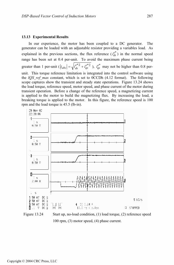
In our experience, the motor has been coupled to a DC generator. Thegenerator can be loaded with an adjustable resistor providing a variables load. As explained in the previous sections, the flux reference ( i ) in the normal speedrange has been set at 0.4 per-unit. To avoid the maximum phase current being
greater than 1 per-unit (
*eds
2*2* eqs
edsabc iii ), may not be higher than 0.8 per-
unit. This torque reference limitation is integrated into the control software using the IQS_ref_max constant, which is set to 0CCDh (4.12 format). The followingscope captures show the transient and steady state operations. Figure 13.24 showsthe load torque, reference speed, motor speed, and phase current of the motor duringtransient operation. Before a change of the reference speed, a magnetizing currentis applied to the motor to build the magnetizing flux. By increasing the load, a breaking torque is applied to the motor. In this figure, the reference speed is 100rpm and the load torque is 45.5 (lb-in).
*eqsi
Figure 13.24 Start up, no-load condition, (1) load torque, (2) reference speed
100 rpm, (3) motor speed, (4) phase current.
Copyright © 2004 CRC Press, LLC
DSP-Based Vector Control of Induction Motors 288
13.14 Conclusion
In this chapter, the theory of field-oriented control of induction motors was described. The structure and organization of software written for the LF2407 DSP controller was also presented. Some technical points and tools were presented to assist in developing a working model for an induction motor drive. The modular structure of this presentation and guidelines allow the reader to quickly grasp the aspects of FOC, thereby assisting the reader in developing software for specific needs.
References
1. Texas Instruments, Implementation of a Speed Field Orientated Control of Three Phase AC Induction Motor using TMS320LF240, Literature Number: BPRA076, March 1998.
2. Texas Instruments, Field Orientated Control of Three Phase AC-motors, Literature Number: BPRA073, December 1997.
Copyright © 2004 CRC Press, LLC