chapter 12 tanks, tanks car, and tank vehicles … · it provides insulation from the sun’s rays...
TRANSCRIPT
7/23/08 4:57 PMFM 10-67-1 CHAPTER 12
Page 1 of 41file:///Volumes/DaVinci/Astra%20Energy%20Web%20Site%20Files/Astra%20Documents/OpProcedures/FM%2010-67-1%20CHAPTER%2012.htm
Solar EnergyWe're finding newer, cleaner ways to powerthe world. Learn how.
AstraGreat deals on everything Astra themed.Yahoo.com
CHAPTER 12
TANKS, TANKS CAR, AND TANK VEHICLES MAINTENANCE AND CLEANING
Section I. Storage Tanks and Tank Maintenance
USE OF STORAGE TANKS
Storage tanks are concrete, steel, and collapsible fabric containers used to store largeamounts of fuel. These tanks must be large enough in size and number to hold fuel for currentdemands and reserve for future needs. Most storage tanks are located at tank farms. Tankfarms are groups of storage tanks and pumps connected by pipelines and manifolds. Thesepipelines and manifolds move fuel into, out of, and between the tanks. Tank farms are part ofbase terminals where tankers are loaded or unloaded, intermediate terminals where fuel isstored until it is needed elsewhere, and head terminals where fuel is issued.
CONCRETE TANKS
Concrete tanks are permanent underground tanks made of reinforced cement. They arecovered with a 4-foot mound of earth as shown in Figure 12-1. Most concrete tanks havemanholes and ladders which provide access to the inside. Pits containing pumps and otherequipment may be located nearby. Most of these tanks are coated or lined on the inside toprevent leaks and to provide a barrier between the fuel and the concrete. These tanks aredifficult to clean and to repair if they develop cracks or leaks. All leaks should be reportedfor maintenance.

7/23/08 4:57 PMFM 10-67-1 CHAPTER 12
Page 2 of 41file:///Volumes/DaVinci/Astra%20Energy%20Web%20Site%20Files/Astra%20Documents/OpProcedures/FM%2010-67-1%20CHAPTER%2012.htm
Figure 12-1. Earthen mound over concrete tank
STEEL TANKS
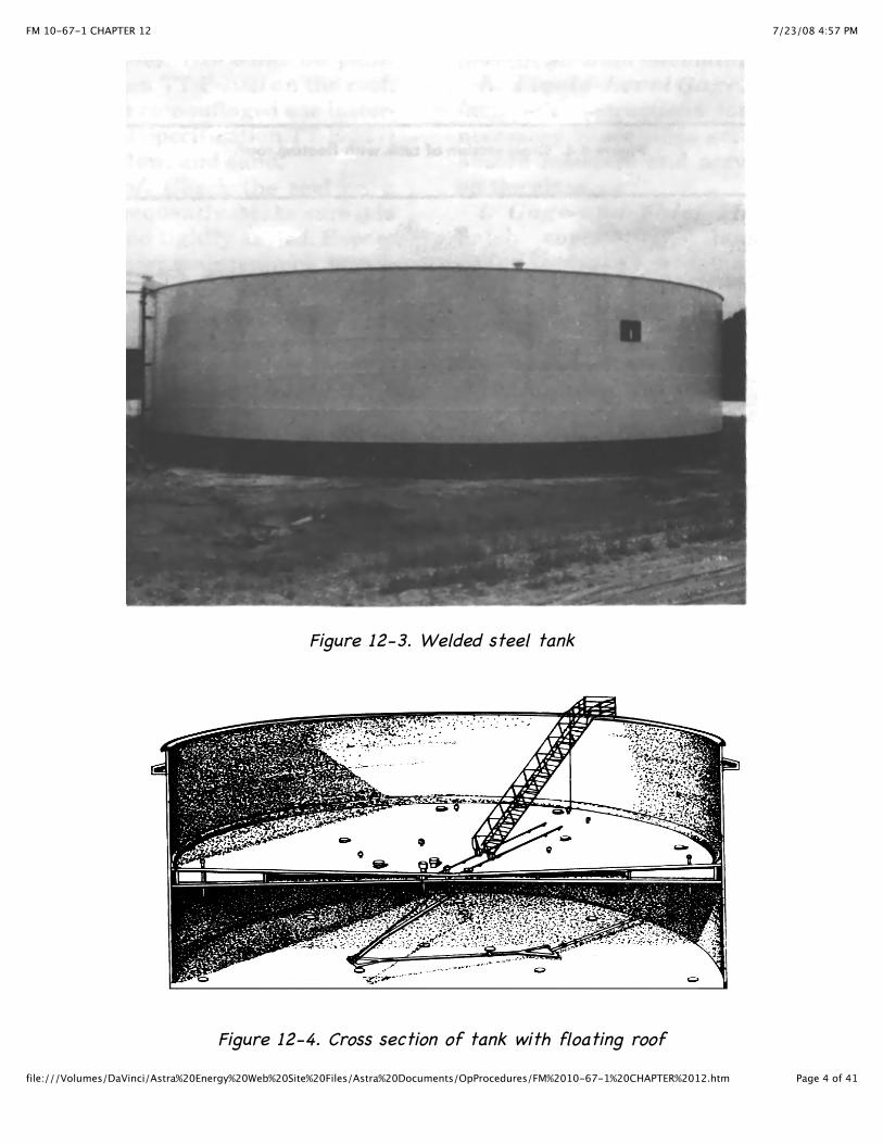
Steel tanks are made of metal plates called staves. These staves are bolted or weldedtogether. Bolted tanks as shown in Figure 12-2 come in 100-, 150-, 250-, 1,000-, 3,000-, and10,000-barrel sizes. Neoprene rubber gaskets are used to seal the edges of the staves and toprevent leaks. Bolted tanks are used aboveground. They are semipermanent because they canbe taken down and reassembled at a new location. The bolted steel cone roof is usedextensively by the military. The tanks have free vents and have a high vapor loss. Weldedtanks as shown in Figure 12-3, will hold volumes in excess of 10,000 barrels of fuel. They arebuilt for permanent use aboveground or buried under a covering of cement or earth. Becauseof the construction it requires skilled personnel. Many aboveground welded tanks have floatingroofs as shown in Figure 12-4. These roofs move up and down with the level of the fuel in thetank. This reduces the amount of vapor in the space above the fuel and lessens the chance ofa fire or explosion. The welded cone roof tank is better suited for the storage of high volatileproducts than the bolted steel tank. In areas subject to bad weather conditions, floating rooftanks with permanent covers or domes have been developed for use. Aboveground bolted andwelded tanks should be built on level foundations that have adequate drainage. Concrete slabor concrete ring foundations are preferred. The outside of the aboveground tanks should bepainted a light color to protect them from corrosion and to reflect heat. Each tank should besurrounded by a firewall high enough to contain all the fuel in the tank in the event of aleak. As a safety measure, 1 foot should be added to the height of the firewall. There are

7/23/08 4:57 PMFM 10-67-1 CHAPTER 12
Page 3 of 41file:///Volumes/DaVinci/Astra%20Energy%20Web%20Site%20Files/Astra%20Documents/OpProcedures/FM%2010-67-1%20CHAPTER%2012.htm
three types of floating roofs:
Pan. The pan type tank is a large, floating pan, slightly smaller in diameter than thetank shell. A system of flexible shoes closes the space between the edge of the roof andthe tank shell.Pontoon. The pontoon type tank has a system of closed compartments or pontoons toincrease floating stability and simplify the structure.Double Deck. The double deck type tank has two separate decks over the entire tanksurface. It provides insulation from the sun’s rays and helps to cut down on loss ofproduct from evaporation.
Figure 12-2. Bolted steel tank
7/23/08 4:57 PMFM 10-67-1 CHAPTER 12
Page 4 of 41file:///Volumes/DaVinci/Astra%20Energy%20Web%20Site%20Files/Astra%20Documents/OpProcedures/FM%2010-67-1%20CHAPTER%2012.htm
Figure 12-3. Welded steel tank
Figure 12-4. Cross section of tank with floating roof

7/23/08 4:57 PMFM 10-67-1 CHAPTER 12
Page 5 of 41file:///Volumes/DaVinci/Astra%20Energy%20Web%20Site%20Files/Astra%20Documents/OpProcedures/FM%2010-67-1%20CHAPTER%2012.htm
COLLAPSIBLE TANKS.
Collapsible fabric tanks as shown in Figure 12-5 are made of elastomeric-coated nylon. Theyare currently available in 3,000-, 10,000-, 50,000-, and 210,000-gallon sizes. They are usedfor the temporary storage of fuel at beachheads, FSSPs, and tank farms. The major advantageof collapsible tanks is that they can be put into service quickly. Most of the time involved isused to prepare a graded site that is surrounded by a firewall.
Figure 12-5. Collapsible fabric tank
INSPECTION AND MAINTENANCE OF STEEL TANKS
When product characteristics of samples exceed deterioration limits, a physical inspectionmust be done on operating tanks and bulk storage tank.. This inspection should take placewhenever a tank’s condition shows evidence of excessive interior rusting or liner deteriorationand microbial problems, and the bottom sludge creates a problem as to the ability of the tankto maintain the quality integrity of the product being stored or issued. Any necessarymaintenance should be performed as soon as possible. The results of the inspections and themaintenance performed on storage tanks should be recorded on DA Form 4177.
Steel Tank Exterior
Check the outside of an aboveground steel tank every month for leaks. Be aware that seepingfuel discolors paint. Repair leaks if possible. Do not try to repair a leak on the bottom of astorage tank. First determine how much fuel is being lost by checking the daily gage recordand then report the leak to support maintenance.

7/23/08 4:57 PMFM 10-67-1 CHAPTER 12
Page 6 of 41file:///Volumes/DaVinci/Astra%20Energy%20Web%20Site%20Files/Astra%20Documents/OpProcedures/FM%2010-67-1%20CHAPTER%2012.htm
Painted Surface
Check for rust and chipped paint on the sides of the tank every month. Check the paint onthe roof every 6 months and spot paint if necessary. Do not paint the entire tank. Painting anentire tank is a support maintenance function. To spot paint areas of the tank, follow thesesteps.
Clean the surface of the tank down to the bare metal with a wire brush.Paint the area with one coat of red lead primer (DOD-P-17545) and allow it to dry.Put two coats of rust-inhibiting semigloss enamel (Federal Specification TT-P-102) on theroof. If the tank has been camouflaged, use lusterless enamel (Federal Specification TT-E-527) in black, brown, yellow, and sand.
Floating Roof
Check the seal on a floating roof tank frequently. Make sure it is in good condition and tightlysealed. Report any damage to support maintenance. Check the roof daily during rainy,freezing, or snowy weather. If the seal has frozen to the tank surface, free the seal beforeraising or lowering the roof. Shovel snow over the side of the tank as soon as possible toprevent the collapse of the roof under the weight of the snow.
Swivel Joint Pipe Drain or Hose
Drain the water off the roof daily by opening the roof drain valve located on the tank shell atthe bottom. Clean the swivel joint pipe drain or hose and the sump. Keep the pipe drain freeof water during freezing weather.
Vents
Remove the screens every 6 months and clean them with dry-cleaning solvent. Check forcorrosion and damage. Repair, repaint, or replace if necessary.
Pressure-Vacuum Breather Valve
Remove the valve as shown in Figure 12-6 every 6 months. Remove debris from the housing.Clean the screens with dry-cleaning solvent or compressed air. Clean pallets, guides, and seatswith dry-cleaning solvent or mild liquid metal polish. If metal polish is used, take care toremove the polish completely. Lubricate stems and guides. Regrind corroded seats and palletsby placing fine grinding compound between the two parts and lightly moving the pallet backand forth on its seat. Then clean the parts as described above.

7/23/08 4:57 PMFM 10-67-1 CHAPTER 12
Page 7 of 41file:///Volumes/DaVinci/Astra%20Energy%20Web%20Site%20Files/Astra%20Documents/OpProcedures/FM%2010-67-1%20CHAPTER%2012.htm
Figure 12-6. Pressure-vacuum breather valve
Flame Arresters
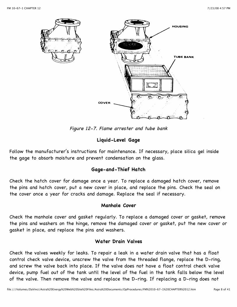
Inspect the outside of flame arresters as shown in Figure 12-7 every 6 months. Clean andspot paint if necessary. Flame arresters have box-shaped tube banks made of flat andcorrugated metal sheets. Remove these tube banks every 6 months and clean them with dry-cleaning solvent or compressed air. Do not remove any of the metal sheets from a tube bank.To prevent damage to the tank during freezing weather, remove the entire flame arresterfrom the tank before the tube banks become clogged with ice and prevent air fromcirculating.
7/23/08 4:57 PMFM 10-67-1 CHAPTER 12
Page 8 of 41file:///Volumes/DaVinci/Astra%20Energy%20Web%20Site%20Files/Astra%20Documents/OpProcedures/FM%2010-67-1%20CHAPTER%2012.htm
Figure 12-7. Flame arrester and tube bank
Liquid-Level Gage
Follow the manufacturer’s instructions for maintenance. If necessary, place silica gel insidethe gage to absorb moisture and prevent condensation on the glass.
Gage-and-Thief Hatch
Check the hatch cover for damage once a year. To replace a damaged hatch cover, removethe pins and hatch cover, put a new cover in place, and replace the pins. Check the seal onthe cover once a year for cracks and damage. Replace the seal if necessary.
Manhole Cover
Check the manhole cover and gasket regularly. To replace a damaged cover or gasket, removethe pins and washers on the hinge, remove the damaged cover or gasket, put the new cover orgasket in place, and replace the pins and washers.
Water Drain Valves
Check the valves weekly for leaks. To repair a leak in a water drain valve that has a floatcontrol check valve device, unscrew the valve from the threaded flange, replace the D-ring,and screw the valve back into place. If the valve does not have a float control check valvedevice, pump fuel out of the tank until the level of the fuel in the tank falls below the levelof the valve. Then remove the valve and replace the D-ring. If replacing a D-ring does not

7/23/08 4:57 PMFM 10-67-1 CHAPTER 12
Page 9 of 41file:///Volumes/DaVinci/Astra%20Energy%20Web%20Site%20Files/Astra%20Documents/OpProcedures/FM%2010-67-1%20CHAPTER%2012.htm
stop a leak, replace the entire valve.
Tank Stairways, Ladders, Handrails, Platforms, and Catwalks
Check these areas to make sure they are safe to use and that they are securely attached tothe tank. Look for corrosion and broken parts. Repair, repaint, or replace them as needed. Payspecial attention to hollow handrails which may have corroded from the inside. Check thetread on stairways and ladders. If it has been worn smooth, it will be slippery when wet.Check platforms and catwalks where water can collect and cause corrosion. A small hole mayneed to be drilled through the metal plate so that water will drain off the surface.
Tank Interior
Make a visual inspection of the inside of the tank at regular intervals (MIL-STD-457). Avisual inspection is made from the cleanout door or shell manhole. The tank should be drainedand ventilated to the point that fuel vapors are no longer explosive. Although it is notnecessary to enter a tank to make a visual inspection, respirators should be worn during theinspection. Table 12-1 shows how often visual inspections should be scheduled.
Table 12-1. Frequency of visual inspections.
Inside of Tank Coated Filter/Separator Usedon Incoming Fuel
Frequency ofInspections
No No Every year
No Yes Every 2 years
Yes No Every 2 years
Yes Yes Every 3 years
REPAIR OF LEAKS IN WELDED STEEL TANKS
A leaking seam in a welded tank can be repaired by rewelding the seam. Such welding can bedone by skilled welders. See TM 9-237. The tank must first be drained, freed of vapor, andcleaned. After obtaining a permit from the safety officer to weld, follow these steps.
Move fire-fighting equipment near the tank.Make sure the welders wear protective clothing and shoes.Remove paint from the surface of the repair area with a wire brush.Make sure the welders use the right size and type of electrodes.Repaint the repair area after the leak has been fixed.
7/23/08 4:57 PMFM 10-67-1 CHAPTER 12
Page 10 of 41file:///Volumes/DaVinci/Astra%20Energy%20Web%20Site%20Files/Astra%20Documents/OpProcedures/FM%2010-67-1%20CHAPTER%2012.htm
REPAIR OF LEAKS IN BOLTED STEEL TANKS
The method used to repair a leak in a bolted steel tank is determined by the size and locationof the leak. In an emergency, a leak caused by a small hole in a stave can be stopped bydriving a wooden leak plug into the hole. Small holes can also be covered with patch boltsthat are inserted from the outside and tightened with a wrench. Large leaks in the metalplate that require replacing one or more staves are beyond the scope of organizationalmaintenance. Leaks at vertical seams can sometimes be stopped by tightening the nuts at theleaks seam with a wrench. Leaks at the chimes (horizontal edges) can usually be repaired byinstalling additional bolts or by replacing the gasket material. To install additional bolts, drillholes between the bolts of the leaking chime. Then use new washers, insert a bolt into eachnew hold, and securely tighten a nut on each bolt. To install new gasket material, take outenough bolts in the leaking chime to remove the gasket material at and around the leak. Thencut out the damaged section of gasket material, and chalk the area with putty. Using newgaskets and washers on the bolts, put the bolts back in and tighten the nuts.
NOTE: Before many of the repairs can be made, the tank must be drained to a level belowthe leak. If repairs must enter a tank to make or finish repairs, the tank must be completelydrained. No one should enter the tank until the fuel vapor level is below the explosive limit.Small repairs which take a short time to complete, such as tightening a nut on a bolt, maythen be made. Repairers must wear protective clothing and respirators. The tank should bevapor freed for longer repairs.
INSPECTION AND MAINTENANCE OF COLLAPSIBLE TANKS
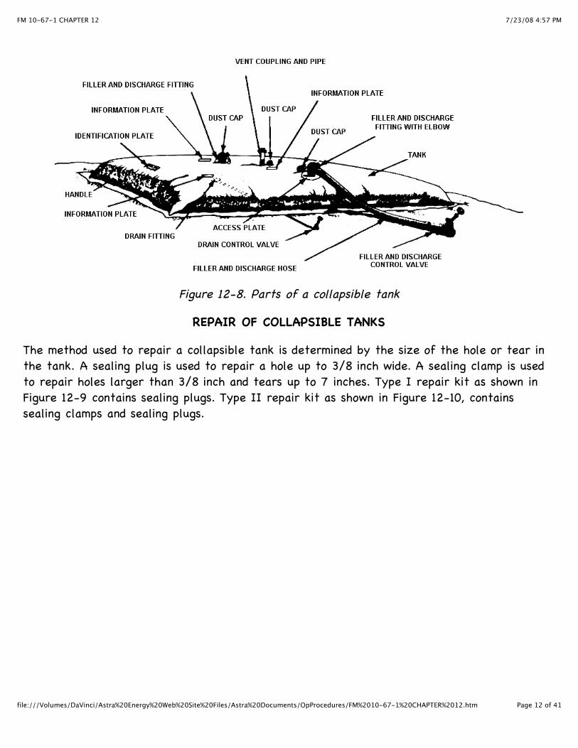
Collapsible tanks should be inspected frequently, and any necessary maintenance performed assoon as possible. Service to collapsible tanks should be recorded on DA Form 2404. TM 5-5430-210-12 has detailed instructions on maintenance, troubleshooting, and repairs. See Figure12-8, to locate parts of the tank.
Inspect and perform maintenance on the following:
Surrounding Area. Check the ground around the tank. Remove sticks, rocks, and sharpobjects that could damage the tank or cause a leaks.Tank Exterior. Check the tank for tears, holes, loose handles, and leaks. Make therepairs if possible.Fill and Discharge Parts. Check the fittings, elbows, and holes for damage and signs of aleak. If necessary, clean the parts with dry-cleaning solvent. Replace worn gaskets andpacking.Vent Pipe. Check the coupling, dust cap, and vent pipe for damage. Look for signs of aleak. Replace worn gaskets. Clean all parts with dry-cleaning solvent. Make sure thedust cap can operate freely to relieve pressure.

7/23/08 4:57 PMFM 10-67-1 CHAPTER 12
Page 11 of 41file:///Volumes/DaVinci/Astra%20Energy%20Web%20Site%20Files/Astra%20Documents/OpProcedures/FM%2010-67-1%20CHAPTER%2012.htm
Drain. This fitting is located on the bottom of the tank at the lower end. Check thefitting and hose for leaks. Replace worn packing and clean all parts with dry-cleaningsolvent.Control Valves. Check the fill and discharge valves. Also, check the drain control valve.Look for leaks. To repair a leak, replace worn gaskets and packing. Clean all parts withdry-cleaning solvent. Look for bent stems. Repair or replace an entire valve if necessary.Tank Interior. Sludge can build up in the bottom of a collapsible tank. Remove thissludge and clean the tank periodically to prevent fuel contamination. Also clean the tankbefore using it to store a different fuel. To clean the inside of a tank, follow thesesteps.
· · Drain the fuel from the tank. · · Remove the access plate on the filler and discharge fitting.
WARNING
Do not inhale fuel vapors.· · Dispose of sludge in a way that is not harmful to the environment as given inparagraph on sludge disposal, page 12-25.
WARNING
Do not allow fuel or sludge to come in contact with theskin.
· · Flush the tank with water. · · Replace the access plate. · · Open the drain and roll up the tank to remove as much water as possible. · · Unroll the tank and close the drain. · · Pump in a few gallons of fuel and roll up the tank again to wet the walls withfuel to prevent cracking. Use the new fuel if service is being changed from one fuelto another. · · Unroll the tank and put it back into use.
7/23/08 4:57 PMFM 10-67-1 CHAPTER 12
Page 12 of 41file:///Volumes/DaVinci/Astra%20Energy%20Web%20Site%20Files/Astra%20Documents/OpProcedures/FM%2010-67-1%20CHAPTER%2012.htm
Figure 12-8. Parts of a collapsible tank
REPAIR OF COLLAPSIBLE TANKS
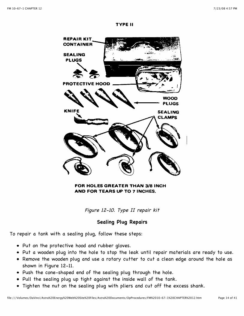
The method used to repair a collapsible tank is determined by the size of the hole or tear inthe tank. A sealing plug is used to repair a hole up to 3/8 inch wide. A sealing clamp is usedto repair holes larger than 3/8 inch and tears up to 7 inches. Type I repair kit as shown inFigure 12-9 contains sealing plugs. Type II repair kit as shown in Figure 12-10, containssealing clamps and sealing plugs.

7/23/08 4:57 PMFM 10-67-1 CHAPTER 12
Page 13 of 41file:///Volumes/DaVinci/Astra%20Energy%20Web%20Site%20Files/Astra%20Documents/OpProcedures/FM%2010-67-1%20CHAPTER%2012.htm
Figure 12-9. Type I repair kit
7/23/08 4:57 PMFM 10-67-1 CHAPTER 12
Page 14 of 41file:///Volumes/DaVinci/Astra%20Energy%20Web%20Site%20Files/Astra%20Documents/OpProcedures/FM%2010-67-1%20CHAPTER%2012.htm
Figure 12-10. Type II repair kit
Sealing Plug Repairs
To repair a tank with a sealing plug, follow these steps:
Put on the protective hood and rubber gloves.Put a wooden plug into the hole to stop the leak until repair materials are ready to use.Remove the wooden plug and use a rotary cutter to cut a clean edge around the hole asshown in Figure 12-11.Push the cone-shaped end of the sealing plug through the hole.Pull the sealing plug up tight against the inside wall of the tank.Tighten the nut on the sealing plug with pliers and cut off the excess shank.

7/23/08 4:57 PMFM 10-67-1 CHAPTER 12
Page 15 of 41file:///Volumes/DaVinci/Astra%20Energy%20Web%20Site%20Files/Astra%20Documents/OpProcedures/FM%2010-67-1%20CHAPTER%2012.htm
Figure 12-11. Repairing a collapsible tank using plugs
Sealing Clamp Repairs
To repair a tank with a sealing clamp, follow these steps.
Put on the protective hood and rubber gloves.Put a wooden plug into the hole if possible to stop the leak until a sealing clamp hasbeen selected.Select the correct size sealing clamp. The shorter side or width of the bottom plate ofthe clamp should fit through the hole or tear. It may be necessary to enlarge the holeor tear slightly by using a knife to insert the bottom plate as shown in Figure 12-12.Fold the hinged stud down and put the bottom plate through the tear.Straighten the stud and rotate the bottom plate so that the longer side or length of thebottom plate is in the same direction as the length of the tear.Slide the upper plate over the stud and tighten the wing nut.
Figure 12-12. Repairing a collapsible tank using clamps
Section II. Tank Cleaning Precautions and Equipment
7/23/08 4:57 PMFM 10-67-1 CHAPTER 12
Page 16 of 41file:///Volumes/DaVinci/Astra%20Energy%20Web%20Site%20Files/Astra%20Documents/OpProcedures/FM%2010-67-1%20CHAPTER%2012.htm
NEED FOR PLANNING AND TRAINING BEFORE TANK CLEANING
During any fuel-handling operation, fuel vapors can accidentally ignite, causing a fire or anexplosion. The chance of this occurring during tank cleaning is especially high. There are otherhealth and physical hazards involved which make tank cleaning dangerous work. The job can beperformed without death, injury, or property damage if the cleaning operation is carefullyplanned step by step and if members of the cleaning detail receive extensive training. Aworking knowledge of the dangers involved and hands-on experience with the safety equipmentare essential. At least two members of the cleaning detail must be trained and tested in firstaid. The training must include cardiopulmonary resuscitation and treatment for vaporinhalation. In addition, the cleaning detail supervisor must prepare a fire plan for the tank inthe event fuel vapors are ignited.
WARNING
Prior to confined space entry, all requirements under the OSHA ConfinedSpace Entry Program must be met.
PREVENTION OF FIRE AND EXPLOSION
The danger of fire and explosion during tank cleaning operations comes from the possibleignition of fuel vapors. The best way to prevent a fire or explosion during tank cleaning,therefore, is to eliminate all sources of ignition and to reduce the concentration of vapors toa point where they will not ignite. Fuel vapors can be ignited when they come in contact witha source of ignition. This is possible only when a certain amount of fuel vapor has beencombined with air. A mixture of 1 to 8 percent fuel vapor and air will ignite at once when itcomes in contact with a spark or flame. The mixture will burn if it is ignited in an open areawhere the hot gases produced have room to expand. The mixture will explode if it has ignitedin a closed space where the heat and gases have no place to go. A mixture with less than 1percent fuel vapor is too lean to ignite. A mixture with more than 8 percent fuel vapor is toorich to ignite. Care must be taken when opening a tank with a mixture too rich to ignite. Thetoo-rich mixture could quickly change to an ignitable mixture after opening the tank. Thehydrogen sulfide vapors found in crude oil tanks are also combustible. They can ignite whenthe hydrogen sulfide content of the tank is between 4.3 percent and 46 percent. So that anexplosion or fire does not occur during tank cleaning operations, the concentration of fuel andhydrogen sulfide vapors must be reduced as quickly as possible to levels that will not ignite.The best way to reduce the concentration is to circulate air through the tank. The airweakens or dilutes the vapor concentration. Eventually the air displaces the vaporscompletely. Care must then be taken to make sure the vapors are not allowed to collect inlow areas outside the tank. These vapors could be ignited outside the tank, and the fire couldspread back to the tank. The other sources of ignition are covered in Chapter 2 of this
7/23/08 4:57 PMFM 10-67-1 CHAPTER 12
Page 17 of 41file:///Volumes/DaVinci/Astra%20Energy%20Web%20Site%20Files/Astra%20Documents/OpProcedures/FM%2010-67-1%20CHAPTER%2012.htm
manual.
HEALTH HAZARDS
The atmosphere inside a tank that has been removed from service is hazardous to health. Thedanger lies in several areas.
Presence of Fuel and Sludge
Physical contact with fuel and sludge can cause serious damage to the skin. Fuel and sludgeremove natural oils, leaving the skin chapped and cracked. These cracks are avenues fordisease and infection to enter the body. Areas of skin wet with fuel or sludge must be washedat once with soap and water. The cleaning detail must wear white clothing so that fuel stainscan be spotted easily. They must also wear rubber gloves and boots to protect their handsand feet.
Presence of Fuel Vapors
Fuel vapors, especially gasoline and jet fuel vapors, are narcotic. Inhaling these vapors canslow the central nervous system to the point that breathing stops. In addition, inhaling evensmall amounts of these vapors can irritate the lungs and respiratory system, causingpneumonia or leaving a person open to other respiratory diseases. The poisonous or toxic limitis 500 parts per million. The cleaning detail must wear respiratory equipment while workinguntil testing the fuel vapors produces a reading at or below that limit. Workers may thenwork in the tank up to 8 hours without respiratory equipment. This does not apply to tanksthat have been used to store leaded fuels.
Presence of Tetraethylead
Tetraethylead is a poisonous liquid. Contact with tetraethylead can result in lead poisoning.Therefore, great care must be taken when entering a tank that has been used to store leadedfuel. Inhaling the fuel vapors can be fatal. Cleaning details must wear respiratory equipmentwhen working in leaded fuel storage tanks. The equipment must be used even after the tankhas been tested and declared vapor free because inhaling dust particles from scale on thewalls can also result in death. Workers must also avoid direct contact with leaded sludgesince lethal amounts of lead can easily be absorbed through the skin. This sludge is dangerouseven after it has been removed from the tank, so great care must be taken with its disposal.The tank is not safe until it has been cleaned down to the bare metal.
Presence of Hydrogen Sulfide
Exposure to hydrogen sulfide can cause death by paralyzing the respiratory system. Victimsbecome unconscious and never regain consciousness. Mild exposure damages the eyes. Hydrogen

7/23/08 4:57 PMFM 10-67-1 CHAPTER 12
Page 18 of 41file:///Volumes/DaVinci/Astra%20Energy%20Web%20Site%20Files/Astra%20Documents/OpProcedures/FM%2010-67-1%20CHAPTER%2012.htm
sulfide, which is found in crude oils with a high sulfur content, can usually be detected by itsrotten egg odor. Be cautious never to use the sense of smell to determine whether or nothydrogen sulfide is present in a tank. Use a piece of moist lead acetate paper instead. Ifhydrogen sulfide is present in the tank, it will blacken the paper. The concentration ofhydrogen sulfide vapor can be measured by a hydrogen sulfide detector. The toxic level is 20parts per million. It is not safe to work in a tank without respiratory equipment until readingsare at or below that level.
Lack of Oxygen
Normal air contains 21 percent oxygen. A concentration of less than 7 percent is dangerous.Fuel vapors in addition to being narcotic, displace oxygen in a tank. Respiratory equipmentmust be used during tank cleaning until a tank has been cleared of fuel vapors. Care mustalso be taken when entering a clean tank that has been closed for a long time. The metalsurface inside may have rusted, using up the oxygen inside the tank. No one should enter sucha tank until fresh air has been allowed to circulate inside the tank. For more on healthhazards, see Chapter 2 of this manual.
PHYSICAL HAZARDS
In addition to fire and health hazards, there are physical hazards involved in tank cleaning.Members of the cleaning detail must take precautions to avoid the following:
Collapse of ladders, scaffolds, and stairways. Make sure they are in good condition andsecurely attached to the tank.Collapse of thin roof sections. Use wooden planks to distribute weight evenly whenworking on a roof.Accidental pumping of fuel into the tank. Make sure lines to the tank are blanked offwith blind flanges or figure eight blinds. Do not depend on closed valves.Tools and objects dropping from above. Handle tools carefully. Do not throw them and donot drop them through the roof manhole. Make sure fixtures inside the tank are securelyattached to the tank and cannot be knocked down. Lower the swivel joint drain pipe toprevent accidental release during cleaning operations.Slipping on wet floors and tripping over hoses, pipes, and fittings. Use extreme cautionwhen moving around inside the tank.Colliding with other workers or tank supports in a poorly lighted tank. Make sure lightingis adequate. Workers must wear white so that they can be seen easily.
SAFETY EQUIPMENT SET
The safety equipment set as shown in Figure 12-13 contains nearly everything necessary toprovide physical and respiratory protection for two members of a cleaning detail. No one must

7/23/08 4:57 PMFM 10-67-1 CHAPTER 12
Page 19 of 41file:///Volumes/DaVinci/Astra%20Energy%20Web%20Site%20Files/Astra%20Documents/OpProcedures/FM%2010-67-1%20CHAPTER%2012.htm
enter a tank without having some experience handling and operating the components of theset.
Figure 12-13. Safety equipment set
Respirators and Air Hoses
Two respirators and four rubber air hoses are in the set. Respirators are face masks whichattach to air hoses. The respirators must be approved by the Bureau of Mines. Whenconnected to a blower, respirators provide an independent supply of fresh air to the wearer.They must be worn at all times inside tanks that were used to store leaded fuel. They mustbe worn inside all other tanks until the tanks have been tested and found to be worn insideclean tanks that have been closed for a long time. The following precautions must be takenwith respirators and air hoses:
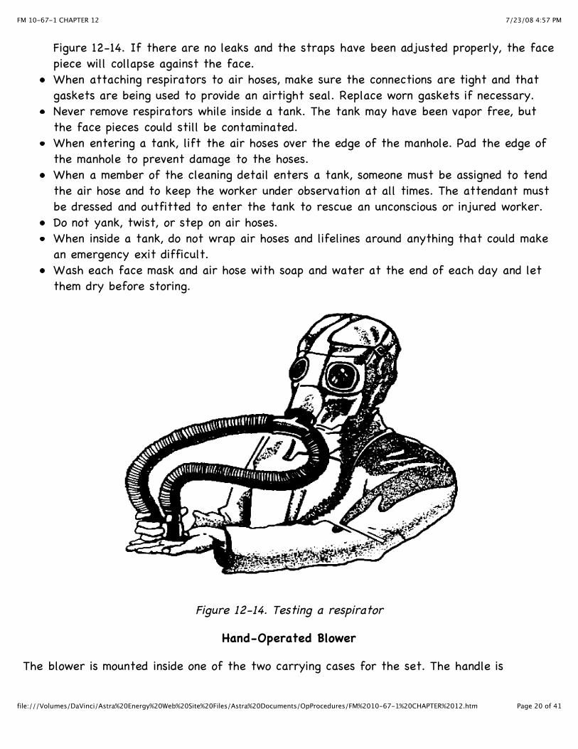
Inspect respirators before each use. Also inspect them before they are stored.Make necessary repairs at once to ensure that the respirators are ready for use at alltimes.Test respirators before each use. To test a respirator, cut off the air supply to themask for a few seconds by covering the end with the palm of the hand as shown in
7/23/08 4:57 PMFM 10-67-1 CHAPTER 12
Page 20 of 41file:///Volumes/DaVinci/Astra%20Energy%20Web%20Site%20Files/Astra%20Documents/OpProcedures/FM%2010-67-1%20CHAPTER%2012.htm
Figure 12-14. If there are no leaks and the straps have been adjusted properly, the facepiece will collapse against the face.When attaching respirators to air hoses, make sure the connections are tight and thatgaskets are being used to provide an airtight seal. Replace worn gaskets if necessary.Never remove respirators while inside a tank. The tank may have been vapor free, butthe face pieces could still be contaminated.When entering a tank, lift the air hoses over the edge of the manhole. Pad the edge ofthe manhole to prevent damage to the hoses.When a member of the cleaning detail enters a tank, someone must be assigned to tendthe air hose and to keep the worker under observation at all times. The attendant mustbe dressed and outfitted to enter the tank to rescue an unconscious or injured worker.Do not yank, twist, or step on air hoses.When inside a tank, do not wrap air hoses and lifelines around anything that could makean emergency exit difficult.Wash each face mask and air hose with soap and water at the end of each day and letthem dry before storing.
Figure 12-14. Testing a respirator
Hand-Operated Blower
The blower is mounted inside one of the two carrying cases for the set. The handle is
7/23/08 4:57 PMFM 10-67-1 CHAPTER 12
Page 21 of 41file:///Volumes/DaVinci/Astra%20Energy%20Web%20Site%20Files/Astra%20Documents/OpProcedures/FM%2010-67-1%20CHAPTER%2012.htm
detachable and mounts on the outside of the case. The blower is operated with the lid closed.When the handle is turned, fresh air is fed through the air hoses to the respirators. Theblower must be set up on the windward side of the tank to make sure the cleaning detail isreceiving fresh air. The blower must be attended at all times while workers are wearingrespirators.
Leather Harnesses and Lifelines
Two leather harnesses and lifelines are in the set. Workers wear harnesses into a tank whenthey wear respirators. The lifelines attach to the back of the harnesses. Lifelines are tendedby the same workers tending the air hoses. Lifelines are used to trace workers inside a tankand to pull unconscious workers to safety. All harnesses and lifelines must be cleaned andallowed to dry before they are stored.
Firemen’s Boots and Rubber Gloves
Four sets of boots and gloves are provided with the safety equipment set. The boots andgloves are fuel resistant. The boots have reinforced toes and nonslip soles. Boots and glovesmust be worn in the tank at all times.
Explosimeter
One explosimeter (combustible gas indicator) as shown in Figure 12-15, two sampling lines, anda probe are in the safety equipment set. An explosimeter is used to determine how explosiveand toxic the atmosphere is inside a tank. The explosimeter must be approved for use by theBureau of Mines.

7/23/08 4:57 PMFM 10-67-1 CHAPTER 12
Page 22 of 41file:///Volumes/DaVinci/Astra%20Energy%20Web%20Site%20Files/Astra%20Documents/OpProcedures/FM%2010-67-1%20CHAPTER%2012.htm
Figure 12-15. Explosimeter
Operation. Squeezing the rubber suction bulb draws an air sample through a probe andsampling line to an analyzer unit. A filament inside the unit burns the fuel vapors in thesample. The flame produced is protected by a flame arrester so that fuel vapors insidethe tank are not ignited. The filament is part of an electrical circuit supplied withcurrent by dry cell batteries. Burning the fuel vapors increases the temperature of thefilament. As a result, there is an increase in the electrical resistance of the filament.This in turn creates a voltage imbalance which moves the needle on the dial of theexplosimeter--the greater the concentration of fuel vapors, the higher the reading.Readings. An explosimeter does not measure what percentage of the volume of a tank ismade up of fuel vapors. It measures how explosive the contents are in a tank. Aconcentration of 1 percent fuel vapors is explosive. A reading of 100 percent on anexplosimeter means that at least 1 percent of the contents of the tank consists of fuelvapors which makes the contents 100 percent explosive. No one should enter a tank whenexplosimeter readings are at or above 100 percent. A reading between 14 percent and100 percent means that the tank is not safe because of toxic vapors. Workers must notgo into the tank unless they are wearing respirators. A reading between 4 percent and14 percent means that workers could go into the tank without respiratory equipment butonly for a very short time. To be on the safe side, such trips should be discouraged. Areading of 4 percent on the explosimeter converts to approximately 500 parts permillion, the toxic limit for fuel vapors. Members of the cleaning detail can work in

7/23/08 4:57 PMFM 10-67-1 CHAPTER 12
Page 23 of 41file:///Volumes/DaVinci/Astra%20Energy%20Web%20Site%20Files/Astra%20Documents/OpProcedures/FM%2010-67-1%20CHAPTER%2012.htm
storage tanks for 8 hours at a time without respiratory equipment when theexplosimeter reading is 4 percent or less.
NOTE: This does not apply to tanks that have been used to store leaded fuels.
Directions for Use. To use an explosimeter, follow these steps.
· · Obtain six fresh 1.5-volt dry cell batteries and put them in the explosimeter. · · Turn on the explosimeter in a vapor-free area outside the tank. · · Flush the explosimeter with fresh air by squeezing the bulb five times. Add twosqueezes for every 10 feet of line if a sampling line is being used. · · Move near the open manhole of the tank and take a sample of the air inside thetank by squeezing the bulb until the reading on the explosimeter remains steady.Wear the proper protective equipment. · · Note the reading. It shows the concentration of combustible vapors in thesample. · · Flush the explosimeter with fresh air after each use. · · Turn the explosimeter off and remove the batteries before storing the unit. · · Service the unit, if necessary, by following the directions in the manufacturer’smanual.
HYDROGEN SULFIDE DETECTOR
The cleaning detail must determine what kind of fuel was stored in a tank before they startany cleaning operation. Tanks that were used to store crude oils must be tested for thepresence of hydrogen sulfide. If the cleaning detail is unable to determine what kind of fuelwas stored in a tank, the tank must be tested for hydrogen sulfide to be on the safe side.Respiratory equipment must be worn during the test. A hydrogen sulfide detector as shown inFigure 12-16 consists of a suction bulb, a glass detector tube, and a frame with a scale. Touse a hydrogen sulfide detector, break off the ends of the glass detector tube and insert thetube in the frame. Squeeze the bulb 10 times to draw a sample into the tube. The reading onthe scale is shown in percent. A content of 4.3 percent to 46 percent hydrogen sulfide isexplosive. The toxic limit is 20 parts per million or .002 percent. Members of the cleaningdetail must not go into a tank until the percent of hydrogen sulfide is less than 4.3 percent.They must not remove respirators until the tank is vapor free.

7/23/08 4:57 PMFM 10-67-1 CHAPTER 12
Page 24 of 41file:///Volumes/DaVinci/Astra%20Energy%20Web%20Site%20Files/Astra%20Documents/OpProcedures/FM%2010-67-1%20CHAPTER%2012.htm
Figure 12-16. Hydrogen Sulfide Detector
FIRE EXTINGUISHERS
A fire caused by ignited vapors is a class B fire. Loaded stream, foam, carbon dioxide, or drychemical fire extinguishers may be used on a class B fire. The extinguishers are available inhand and wheel units. Members of the cleaning detail should know how to operate these fireextinguishers. Fire extinguishers are effective only in the first stages of a fire, so thecleaning detail should be trained to act quickly. See Chapter 2 for more information aboutclasses of fire and fire extinguishers.
PROTECTIVE CLOTHING AND EQUIPMENT
Members of the cleaning detail must wear clean, white cotton coveralls when they go inside atank. White must be used because it is easily seen inside a dim tank and it shows fuel stainseasily. Cotton must be used because it cuts down on the generation of static electricity. Allprotective clothing must be laundered at the end of each workday. To protect the team fromfalling objects and debris, they must wear safety helmets when they go inside the tank.When respirators are no longer needed, they must wear goggles to protect their eyes fromloose scale and cleaning solvents in the tank.
Section III. Storage Tank Cleaning
RESPONSIBILITY
Vapor freeing, decontaminating, and cleaning tanks are organizational maintenance activitieswith two exceptions. Cleaning fixed tanks to apply rust proofing and coatings to the insidesurface is the responsibility of the facilities engineer. Cleaning fixed tanks that are a part ofmotor pools, service stations, and aircraft fueling systems is also the responsibility of thefacilities engineer. A tank should not be cleaned unless it is absolutely necessary. It isnecessary to drain, vapor free, and clean a tank when the following actions take place.
7/23/08 4:57 PMFM 10-67-1 CHAPTER 12
Page 25 of 41file:///Volumes/DaVinci/Astra%20Energy%20Web%20Site%20Files/Astra%20Documents/OpProcedures/FM%2010-67-1%20CHAPTER%2012.htm
Inspections
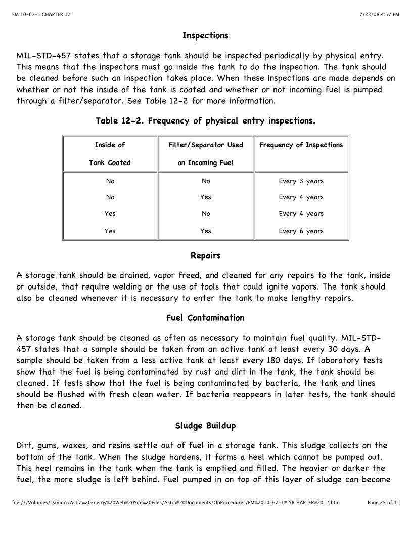
MIL-STD-457 states that a storage tank should be inspected periodically by physical entry.This means that the inspectors must go inside the tank to do the inspection. The tank shouldbe cleaned before such an inspection takes place. When these inspections are made depends onwhether or not the inside of the tank is coated and whether or not incoming fuel is pumpedthrough a filter/separator. See Table 12-2 for more information.
Table 12-2. Frequency of physical entry inspections.
Inside of
Tank Coated
Filter/Separator Used
on Incoming Fuel
Frequency of Inspections
No
No
Yes
Yes
No
Yes
No
Yes
Every 3 years
Every 4 years
Every 4 years
Every 6 years
Repairs
A storage tank should be drained, vapor freed, and cleaned for any repairs to the tank, insideor outside, that require welding or the use of tools that could ignite vapors. The tank shouldalso be cleaned whenever it is necessary to enter the tank to make lengthy repairs.
Fuel Contamination
A storage tank should be cleaned as often as necessary to maintain fuel quality. MIL-STD-457 states that a sample should be taken from an active tank at least every 30 days. Asample should be taken from a less active tank at least every 180 days. If laboratory testsshow that the fuel is being contaminated by rust and dirt in the tank, the tank should becleaned. If tests show that the fuel is being contaminated by bacteria, the tank and linesshould be flushed with fresh clean water. If bacteria reappears in later tests, the tank shouldthen be cleaned.
Sludge Buildup
Dirt, gums, waxes, and resins settle out of fuel in a storage tank. This sludge collects on thebottom of the tank. When the sludge hardens, it forms a heel which cannot be pumped out.This heel remains in the tank when the tank is emptied and filled. The heavier or darker thefuel, the more sludge is left behind. Fuel pumped in on top of this layer of sludge can become

7/23/08 4:57 PMFM 10-67-1 CHAPTER 12
Page 26 of 41file:///Volumes/DaVinci/Astra%20Energy%20Web%20Site%20Files/Astra%20Documents/OpProcedures/FM%2010-67-1%20CHAPTER%2012.htm
contaminated. When bottom samples show fuel contamination or when gagging reveals that toomuch sludge has built up, the tank should be cleaned.
Change of Product
A tank should be used to store only one kind of fuel so that quality can be maintained. If theservice of a tank has to be changed from one fuel to another, the tank should be cleanedbefore pumping in the new fuel. See MIL-HDBK-200, Table V, for guidelines.
NOTE: The service of a tank may be upgraded by gradually pumping in fuel of a higher qualitythan that previously pumped into the tank. Fuel contamination will always be a result of suchan upgrade. This should be taken into consideration before a decision is made to use thismethod to change service. This method should never be used to make radical changes. Forexample, the method should not be used to change tank service from diesel fuel to AVGAS.
Removal of Tank from Service
If a decision is made to take a storage tank out of service for longer than 4 months, thefollowing actions should be taken:
All concrete tanks should be cleaned.Steel tanks used to store fuel oil, diesel fuel, and lubricating oil should be cleaned. Theyshould then be coated with the same product they contained. This will preserve themetal.Steel tanks used to store gasoline, jet fuel, and kerosene should be cleaned and thencoated with general-purpose lubricating oil (Federal Specification VV-L-800) to preservethe metal.Steel tanks to be dismantled should be cleaned and coated with general-purposelubricating oil.
NOTE: It is not necessary to coat a tank that was taken down to move it to a new site forreassembly.
Reactivation of Tank
If a decision is made to put an inactive tank back into service, the following actions should betaken:
· Steel tanks that have stood empty for sometime should be cleaned to remove the rustwhich may have formed on the inside. · Steel tanks that were coated with lubricating oil should be cleaned before they areused to store gasoline, jet fuel, or kerosene. · Inactive tanks that were ballasted with water or fuel should be cleaned to remove rust

7/23/08 4:57 PMFM 10-67-1 CHAPTER 12
Page 27 of 41file:///Volumes/DaVinci/Astra%20Energy%20Web%20Site%20Files/Astra%20Documents/OpProcedures/FM%2010-67-1%20CHAPTER%2012.htm
and sludge.
FACILITIES ENGINEER DUTIES
When there is a reason to justify cleaning a tank, the facilities engineer is notified. Thefacilities engineer should--
Determine the need to enter any tank that has been used to store leaded fuel.Determine the need to enter any other tank capable of holding 1,000 or more barrels offuel.Make sure there is a safety equipment set available for use.Obtain the services of a safety engineer experienced in tank cleaning safety. The safetyengineer should be present when any tank containing leaded fuel is entered. The safetyengineer should also be present when any tank capable of holding 1,000 or more barrelsof fuel is entered.Request medical advice from The Surgeon General (AR 200-1), if necessary.Obtain the services of a contractor to clean a tank if local demand for tank cleaning isso infrequent that the local work force cannot maintain a level of expertness (AR 420-49). The contractor should be instructed to provide all the equipment and take all theprecautions necessary to protect life, health, and property.
CLEANING DETAIL SUPERVISOR DUTIES
The cleaning detail supervisor oversees all cleaning operations. The cleaning supervisor should--
Gather the following information:
· · Kind of fuel stored in the tank. · · Reason for cleaning the tank. · · Condition of the tank and any repairs to be made. · · Amount of corrosion and sludge present in the tank. · · Last date the tank was cleaned and how well it was cleaned.
Train the cleaning detail. This training must include instruction on the dangers involved intank cleaning, the use of the safety equipment set, and the safety precautions thatapply to tank cleaning.Prepare a fire plan for the tank. Everyone should know what is expected of him in theevent of a fire or explosion.Delegate various jobs to specific members of the cleaning detail.Make sure at least two members of the detail have recently been trained and tested incardiopulmonary resuscitation.
7/23/08 4:57 PMFM 10-67-1 CHAPTER 12
Page 28 of 41file:///Volumes/DaVinci/Astra%20Energy%20Web%20Site%20Files/Astra%20Documents/OpProcedures/FM%2010-67-1%20CHAPTER%2012.htm
Determine whether or not every member of the detail is in good physical condition andable to working in the tank. Workers who are tired or sick will develop more problemsinside the tank.Inspect all safety equipment to make sure it is in good condition and ready for use.Make sure fire-fighting equipment is nearby.Arrange for the safe disposal of sludge. See AR 200-1.Contract, if necessary, for the use of a vacuum truck to remove sludge and haul it to adisposal area.Furnish the environmental engineer with information on the tank and sludge disposal toobtain a safety permit.Examine the area around the tank to make sure all sources of ignition have beenremoved.Make sure the tank is isolated before starting cleaning operations.Be present during cleaning operations to provide instruction and guidance.Make sure no one enters the tank until vapor readings are in the safe zone.Tell members of the cleaning detail to leave the tank if they smell fuel vapors.
TOOLS AND EQUIPMENT
In addition to the safety equipment and clothing already described, other tools and equipmentare needed to clean a tank. Make sure the following items are on hand before startingcleaning operations:
Blind flanges or Figure eight blinds to provide positive shutoff to the tank.Pump to move sludge from tank bottom to tank vehicle.Tank vehicle or vacuum truck to carry sludge to disposal site.Air eductor or ejector to raw fuel vapors out of the tank.Blowers or fans to drive fuel vapors out of the tank.Shovels, scrapers, wire brushes, buckets, and wheelbarrows.Long-handled push brooms, scrub brushes, squeegees, and mops.Towels, washcloths, and bath soap for each member of the cleaning detail.Water hose and nozzle.Disinfectant for face masks.Clean rags and airtight metal cans to store oily rags until they can be destroyed.First aid kits.Wrenches and tools necessary to blank off the tank, enter the tank, and tighten loosetank accessories.Warning signs to post during tank cleaning.Sign-painting kit and yellow paint to stencil tank after cleaning.Ladders and scaffolding to reach upper areas of the tank shell.Detergents, cleaning solvents, and kerosene.

7/23/08 4:57 PMFM 10-67-1 CHAPTER 12
Page 29 of 41file:///Volumes/DaVinci/Astra%20Energy%20Web%20Site%20Files/Astra%20Documents/OpProcedures/FM%2010-67-1%20CHAPTER%2012.htm
ISOLATING A TANK
Before vapor-freeing and cleaning operations can begin, a tank should be isolated. The tankshould be completely cut off from the rest of the terminal and pipeline system. There shouldbe no way to accidentally pump fuel into the tank. There should also be no way for fuelvapors to drift back into the tank after it has been vapor freed. To isolate a tank, followthese steps.
Use the lowest tank connection and pump or drain as much fuel as possible out of thetank. If necessary, pump in enough water to cover the tank bottom. What fuel is leftand the sludge that had not hardened will float on top of the water. Pump this liquidsludge to a tank vehicle and then draw off the water. Do not allow oily water to spill onthe ground. Be aware that some tanks, especially underground ones, may havepermanently installed sump pumps for removing liquid sludge. Some may even have theirown sludge disposal systems to pipe sludge to a disposal area.
NOTE: Never pump water into a concrete tank.
Close the valves outside the firewall on all lines going to and from the tank. Attach asign to each valve, warning workers not to open the valves.Drain and flush all the lines into the tank.Break all lines and remove the valves nearest to the tank. Replace the valves witheither blind flanges or figure eight blinds as shown in Figure 12-17. Make sure the solidhalf of the figure eight blind is down in the line. If figure eight blind holders havealready been permanently installed near the tank, it is not necessary to remove thevalves. Reverse the blinds so that the solid half closes off the line. All blank ends andblinds should be strong enough to withstand any pressure that might be exerted in theline. Respirators should be worn when blanking lines to tanks which were used to storeleaded fuels and crude oils.
Figure 12-17. Blanking off a tank with blind flanges or figure eight blinds

7/23/08 4:57 PMFM 10-67-1 CHAPTER 12
Page 30 of 41file:///Volumes/DaVinci/Astra%20Energy%20Web%20Site%20Files/Astra%20Documents/OpProcedures/FM%2010-67-1%20CHAPTER%2012.htm
VAPOR FREEING A TANK
Vapor freeing is actually the complete replacement of fuel vapors in a tank with fresh air. Atank is usually considered vapor free when the concentration of fuel vapors is below the toxicand combustible levels. Vapor freeing is a dangerous operation. Workers who open themanholes and cleanout doors of leaded fuel or crude oil tanks should wear respirators. No oneshould be in the area around the tank during vapor freeing except for those who approachthe tank from time to time to conduct vapor tests. Several methods are used to vapor freetanks. Some methods are better than others. The method used depends on the kind of tankbeing cleaned and the situation.
Natural Ventilation
Natural ventilation, or airing, is the easiest method to use. Its main advantage is that it usesnatural forces. It require little or no equipment and no outside power source. However, thereare several disadvantages to this method. First it takes longer than other methods. Theconcentration of vapors inside the tank is explosive and toxic for a longer period of time.Vapors may collect at ground level outside the tank creating another hazard. Second, thismethod is not practical for underground tanks because of the lack of natural circulation. Toventilate a tank naturally-
Remove the roof manhole cover.Remove the tank shell manhole cover or cleanout door.Allow air to circulate freely through the tank.Take vapor readings periodically. Do not start sludge removal until the tank is vaporfree.
Forced Ventilation
Forced ventilation uses an outside force to direct the flow of air into the tank. This speedsthe vapor freeing process. This is the most commonly used method. Two methods are used toforce ventilate a tank.
Blower or fan method. A blower or fan usually installed in the tank shell manhole orcleanout door is used to blow fresh air into the tank. Fuel vapors escape through theroof manhole. The blower or fan, may be steam-turbine, gasoline-engine, or electric-motor driven. Gasoline-powered units should be located away from the tank on thewindward side. They should be equipped with spark arresters. Canvas ducts are used tocarry the air to the tank. Electric-motor driven units should be explosion proof. To use ablower or fan--
· · Open the tank shell manhole or cleanout door.
7/23/08 4:57 PMFM 10-67-1 CHAPTER 12
Page 31 of 41file:///Volumes/DaVinci/Astra%20Energy%20Web%20Site%20Files/Astra%20Documents/OpProcedures/FM%2010-67-1%20CHAPTER%2012.htm
· · Set up gasoline-engine powered units away from the tank and lay canvas ductson the ground to the tank opening. Mount other units in the tank opening. Whenusing this method to vapor free underground tanks, attach the blowers to pipesleading to the tank bottom or to ducts or hoselines. These ducts or hoselines arefed through roof openings to the tank bottom. · · Remove the roof manhole cover. · · Start the blower and ventilate the tank until vapor readings are in the safezone.
Air ejector or eductor method. An air ejector, or eductor, is used to draw fuel vaporsout of the top of the tank. The unit is installed in the roof manhole. Fresh air is allowedto enter through the tank shell manhole or cleanout door. To use an air ejector oreductor--
· · Open the roof manhole and install the unit. · · Operate the unit to create a pressure differential between the inside andoutside of the tank. Use the low setting at this point to avoid creating a vacuum. · · Once a pressure differential has been established, open the tank shell manholeor cleanout door. This allows fresh air to be drawn into the tank. In undergroundtanks, open pipes leading into the bottom of the tank. · · Operate the unit at full speed until the tank is vapor free.
Steam Ventilation
This method uses steam to displace fuel vapors. Steam ventilation has many disadvantages. Itsuse is discouraged except in tanks where iron sulfide is known to be present. On largediameter tanks, steam is not effective; however, it is effective on tank trucks and rail cars.The disadvantages are--
It generates static electricity which could ignite vapors.It is a slow method. Producing enough steam to displace fuel vapors in a large tank isdifficult.The temperature must be at least 170° F to prevent condensation. This temperature isdifficult to maintain in cold weather.Steam damages the linings of coated tanks and causes cracks in concrete tanks. Itshould never be used to vapor free a concrete tank.
Water Displacement
This method uses water to take the place of fuel vapors in the tank. Fuel vapors exit as thetank is filled to overflowing. The oily water produced by this process has to be treatedbefore disposal. Water displacement is practical for small tanks only. It should not be used in
7/23/08 4:57 PMFM 10-67-1 CHAPTER 12
Page 32 of 41file:///Volumes/DaVinci/Astra%20Energy%20Web%20Site%20Files/Astra%20Documents/OpProcedures/FM%2010-67-1%20CHAPTER%2012.htm
areas where water supplies are limited.
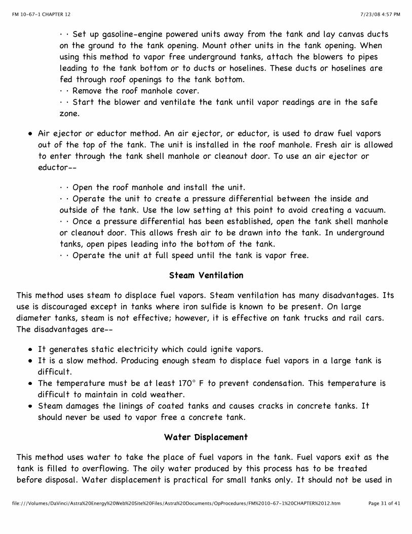
VAPOR TEST
Periodic vapor tests are made during vapor-freeing operations. They are made with anexplosimeter and, if necessary, a hydrogen sulfide detector. The tests are made to check onthe progress of the vapor freeing. Vapor tests are also conducted during tank-cleaningoperations to make sure the tank is safe for members of the cleaning detail. To conduct avapor test--
Read the manufacturer’s manuals and the paragraphs on explosimeter and hydrogensulfide detector in this section.Wear a respirator and approach an open cleanout door or tank shell manhole. Insert theprobe through the door as shown in Figure 12-18. Take the first reading in the areawhere vapors are leaving the tank. Do not enter the tank at this time.Step inside the tank to take readings when the readings from the opening fall to 14percent. Hold the probe about 1 foot above the sludge. Turn off fans, blowers, andeductors while testing to get a true sample of the air in the tank.
WARNING
If samples are also being taken with a hydrogen sulfide detector, donot enter the tank until readings from the door are at or below the4.3 percent explosive limit for hydrogen sulfide.
Take samples often at various points inside the tank. Leave the tank between tests.Flush out the explosimeter with fresh air and reset at 0. Put a new glass tube in thehydrogen sulfide detector for each test.Repeat the tests until explosimeter readings are at or below the toxic limit of 4percent. If samples are also being taken with a hydrogen sulfide detector, repeat thetests with the detector until readings are at or below the toxic limit of .002 percent.Continue to take samples after members of the cleaning detail have entered the tank tostart sludge removal operations. Additional fuel vapors may be trapped in the sludge.These vapors will be released when the sludge is disturbed. If readings reach dangerouslevels, members of the cleaning detail should leave the tank. They should not reenter thetank until readings are again in the safe zone.
7/23/08 4:57 PMFM 10-67-1 CHAPTER 12
Page 33 of 41file:///Volumes/DaVinci/Astra%20Energy%20Web%20Site%20Files/Astra%20Documents/OpProcedures/FM%2010-67-1%20CHAPTER%2012.htm
Figure 12-18. Vapor testing at cleanout door
CLEANING OPERATIONS
After a tank has been declared vapor free, members of the cleaning detail can usually enterthe tank to begin cleaning operations. Some underground steel tanks may not be entered.These tanks should be cleaned using the method described in the paragraph on cleaninguncoated tank cars and tank vehicles, page 12-8. To clean tanks that do allow entry--
Stencil a warning sign near the entrance to the tank if the tank was used to storeleaded fuel. Wear respirators in the tank and use forced ventilation until the tank hasbeen cleaned down to the bare metal.Before starting to work, inspect the inside of the tank for loose fixtures and repair thetank if necessary. Lower the swivel joint drain pipe to the tank floor.Use a high-pressure water hose to dislodge sludge, loose rust, and scale.Continue to take vapor tests. Leave the tank if readings show toxic concentrations offuel vapors. Since it takes more time to leave an underground tank than an abovegroundtank, an increase in the concentration of fuel vapors in an underground tank should bedetected quickly.Lay a suction hose in the tank and use a pumping assembly to pump liquid sludge to atank vehicle as shown in Figure 12-19. If a vacuum truck is being used, the pumpingassembly is not necessary.Brush, sweep, or scrap the remaining sludge into piles and shovel it into buckets orwheelbarrows.

7/23/08 4:57 PMFM 10-67-1 CHAPTER 12
Page 34 of 41file:///Volumes/DaVinci/Astra%20Energy%20Web%20Site%20Files/Astra%20Documents/OpProcedures/FM%2010-67-1%20CHAPTER%2012.htm
Use wire brushes and scrapers to remove rust and scale from the uncoated surface oftank walls and floor. Use scaffolds or ladders to get to out-of-reach areas.Dispose of the sludge and debris.Clean the tank, fixtures, and supports. If necessary, drill small holes at the bottom ofhollow structures and supports. Flush them from the top with water and allow to drain.Scrub the walls and floor with kerosene, cleaning solvent, or detergents, if necessary. Donot damage tank coatings.Rinse the walls and floor with water. Mop up all water and wipe dry with lint-free rags.
Figure 12-19. Pumping sludge to tank vehicle
SLUDGE DISPOSAL
The cleaning detail supervisor should arrange for the disposal of the sludge. All activitiesshould be coordinated with the environmental engineer whose job it is to consider the effector impact the disposal of the sludge will have on the environment. The method used to get ridof the sludge should not damage the environment or harm humans or animals (AR 200-1). Forthese reasons, sludge cannot be buried or carelessly dumped on the ground.
Unleaded or Nonhydrogen Sulfide Sludge
Sludge that does not contain lead, hydrogen sulfide, or other harmful chemicals can bedisposed of by farming or weathering.
7/23/08 4:57 PMFM 10-67-1 CHAPTER 12
Page 35 of 41file:///Volumes/DaVinci/Astra%20Energy%20Web%20Site%20Files/Astra%20Documents/OpProcedures/FM%2010-67-1%20CHAPTER%2012.htm
Farming. Sludge can be farmed at selected sites. These sites should be level, welldrained, well ventilated, and sunny. The sludge should be hauled to the site, evenlydistributed on the ground, and plowed in with the topsoil. Later the land can be used togrow crops.Weathering. Sludge can be weathered at selected sites similar to those used forfarming. An even layer of sludge 3 inches deep should be spread on the ground withhoes, rakes, and shovels. The area should be roped off and warning signs put up. Thesludge should be left undisturbed for 4 weeks (or longer if the temperature is belowfreezing). The rope and sign can be taken down after the weathering is complete. Thesludge can then be left there, or it can be hauled away.
Leaded or Hydrogen Sulfide Sludge
Sludge that contains lead, hydrogen sulfide, or other harmful chemicals can be disposed of bycontrolled burning or by depositing it at specified sites.
Controlled burning. Harmful sludge can be burned in high-intensity heat furnaces that donot give off emissions.Depositing at specified site.Sludge can be taken to hazardous materials disposal sites. These sites are speciallydesignated areas which have been set aside permanently for the disposal of dangeroussubstances such as nuclear wastes and toxic chemicals. The disposal sites must also beapproved by EPA. All trucks used to transport sludge must be approved by state andfederal agencies and a certificate issued for each vehicle.
AFTER-CLEANING OPERATIONS
Certain tasks should be done when the cleaning detail finishes mopping up in the tank. The jobis not complete until these final tasks are done.
Tools and Equipment
Dispose of the rags and brooms used to clean leaded fuel and crude oil with the sludge fromthese tanks. Thoroughly clean all other tools and equipment with soap and water. You can usekerosene if necessary. Disinfect face masks. Allow all pieces in the safety equipment set todry before storing them.
Pumping Assembly
To clean the pump assembly--
Put the end of a suction hose into a barrel or drum of clean water. Attach the hose to awater faucet or couple the hose to a water hose.

7/23/08 4:57 PMFM 10-67-1 CHAPTER 12
Page 36 of 41file:///Volumes/DaVinci/Astra%20Energy%20Web%20Site%20Files/Astra%20Documents/OpProcedures/FM%2010-67-1%20CHAPTER%2012.htm
Start the pump and if necessary, turn on the water. Run the pump until the pump andthe hose have been thoroughly flushed with water. Dispose of the water in a way that isnot harmful to the environment.Put the end of the suction hose into a drum or container of solvent. Flush the pump andthe hoses with 1 or 2 gallons of solvent. Drain the solvent from the pump and hoses.
Stenciled Sign
Use yellow paint to stencil the cleaning date on the tank near the tank shell manhole orcleanout door.
Tank Ballast
Ballast or weight steel tanks that are being taken out of service in hurricane areas toprevent them from being blown away. Ballast empty steel tanks in flood areas to preventthem from floating away.
NOTE: Ballasting is not a common practice. It should be done only if past experience hasshown it to be necessary. Light fuels or water with a rust inhibitor can be used for ballast.Water should not be used as ballast in areas where there is a chance it will freeze. Also, ifother ballast is available, water should not be pumped into tanks which will be used to storegasoline, jet fuel, or kerosene.
Hygiene
At the end of each work day and at the end of the job, make sure all members of thecleaning detail bathe with soap and water and change to clean clothes.
DA Form 4177
Complete DA Form 4177. Enter the cleaning date and any other important facts.
Section IV. Tank Car and Tank Vehicle Cleaning
RESPONSIBILITY FOR INSPECTING AND CLEANING
Tank cars and tank vehicles should be inspected before each use according to MIL-HDBK-200.The inside of the tank, including the dome, should be free of rust, scale, dirt, and sludgebefore new fuel is loaded. These inspections should be made by those responsible for loadingthe fuel. Organizational maintenance personnel are responsible for cleaning the inside of tankcars and tank vehicles, whenever necessary, to prevent fuel contamination. They are alsoresponsible for cleaning tank cars and tank vehicles for a change in service or for repairs thatcould ignite vapors.

7/23/08 4:57 PMFM 10-67-1 CHAPTER 12
Page 37 of 41file:///Volumes/DaVinci/Astra%20Energy%20Web%20Site%20Files/Astra%20Documents/OpProcedures/FM%2010-67-1%20CHAPTER%2012.htm
SAFETY PRECAUTIONS
The same dangers that are present during the cleaning of bulk storage tanks are presentduring the cleaning of tank cars and tank vehicles. Cleaning detail members should be familiarwith the safety equipment and follow the same safety precautions described in Section II ofthis Chapter.
CLEANING UNCOATED TANK CARS AND TANK VEHICLES
Some tank cars and all tank vehicles have uncoated steel interiors. These tank units should bevapor freed and cleaned using steam. Steam cleaning should also be used to clean undergroundsteel tanks that do not allow entry. To clean a tank with steam--
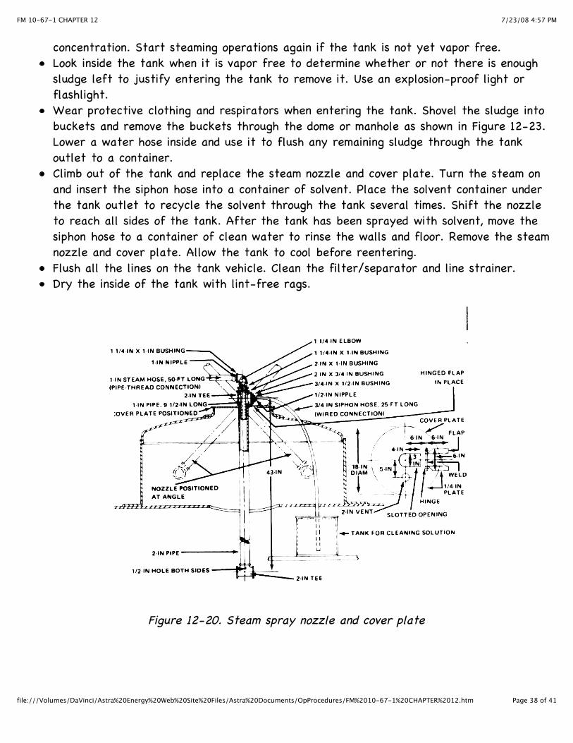
Move the tank car to a bypass or spur track. Move the tank vehicle to an open areaoutdoors. Set the brakes. Lock derails in place at each end of the tank car. Chock thewheels of the tank car or tank vehicle.Remove all sources of ignition in the area. Do not start the engine of a tank vehicleduring cleaning operations.Put up signs warning of the danger of tank cleaning.Drain the tank car or tank vehicle of all fuel.Arrange for a supply of steam.Obtain or make a steam spray nozzle and cover plate as shown in Figure 12-20.Contact the environmental engineer and arrange for the disposal of sludge. See AR 200-1.Place a container under the tank car or tank vehicle to catch sludge. If necessary, havemore containers available.Remove the dome or manhole cover.Bond the steam nozzle to the tank shell with a bare copper wire. Check the rails underthe tank car for correct bond and ground as shown in Figure 12-21. To ground the trackvehicle-
· · Drive a grounding rod about 3 feet into the ground. Soak the area around therod with water to get a better ground. · · Unwind the ground cable from the tank vehicle. Attach the cable clip to thegrounding rod as shown in Figure 12-22.
If the tank car or vehicle has only one compartment, steam the tank for an hour. Checkthe tank outlet. If the steam of condensation and liquid sludge is still heavy, continue tosteam until the flow of sludge stops. If the tank car has more than one compartment,steam clean each one until sludge no longer flows from the outlet. Allow the tank tocool.Insert the pole of an explosimeter through the dome or manhole. Test for vapor
7/23/08 4:57 PMFM 10-67-1 CHAPTER 12
Page 38 of 41file:///Volumes/DaVinci/Astra%20Energy%20Web%20Site%20Files/Astra%20Documents/OpProcedures/FM%2010-67-1%20CHAPTER%2012.htm
concentration. Start steaming operations again if the tank is not yet vapor free.Look inside the tank when it is vapor free to determine whether or not there is enoughsludge left to justify entering the tank to remove it. Use an explosion-proof light orflashlight.Wear protective clothing and respirators when entering the tank. Shovel the sludge intobuckets and remove the buckets through the dome or manhole as shown in Figure 12-23.Lower a water hose inside and use it to flush any remaining sludge through the tankoutlet to a container.Climb out of the tank and replace the steam nozzle and cover plate. Turn the steam onand insert the siphon hose into a container of solvent. Place the solvent container underthe tank outlet to recycle the solvent through the tank several times. Shift the nozzleto reach all sides of the tank. After the tank has been sprayed with solvent, move thesiphon hose to a container of clean water to rinse the walls and floor. Remove the steamnozzle and cover plate. Allow the tank to cool before reentering.Flush all the lines on the tank vehicle. Clean the filter/separator and line strainer.Dry the inside of the tank with lint-free rags.
Figure 12-20. Steam spray nozzle and cover plate

7/23/08 4:57 PMFM 10-67-1 CHAPTER 12
Page 39 of 41file:///Volumes/DaVinci/Astra%20Energy%20Web%20Site%20Files/Astra%20Documents/OpProcedures/FM%2010-67-1%20CHAPTER%2012.htm
Figure 12-21. Grounding a tank car

7/23/08 4:57 PMFM 10-67-1 CHAPTER 12
Page 40 of 41file:///Volumes/DaVinci/Astra%20Energy%20Web%20Site%20Files/Astra%20Documents/OpProcedures/FM%2010-67-1%20CHAPTER%2012.htm
Figure 12-22. Grounding a tank vehicle
Figure 12-23. Removing sludge
CLEANING COATED TANK CARS
Some tank cars are coated on the inside to prevent rust. Never use steam to vapor free andclean a coated tank because steam can damage the coating badly. To vapor free and clean acoated tank car--
Move the tank car to a bypass or spur track. Set the brakes. Lock derails in place ateach end of the tank car. Chock the wheels as an added measure.Remove all sources of ignition. Check the rails under the car for correct bond andground.Post warning signs.Drain all the fuel from the tank car.Remove the dome cover.Mount an air ejector or eductor in the dome to drain fuel vapors out of the car bysuction. The air ejector may be powered by steam or compressed air. Bond the unit tothe tank before operating it.
7/23/08 4:57 PMFM 10-67-1 CHAPTER 12
Page 41 of 41file:///Volumes/DaVinci/Astra%20Energy%20Web%20Site%20Files/Astra%20Documents/OpProcedures/FM%2010-67-1%20CHAPTER%2012.htm
Operate the air ejector until the tank is vapor free. Periodically, stop to test for fuelvapors with an explosimeter.Place a container under the tank car to catch sludge, solvents, and oily water aftervapor-freeing operations are finished.Open the tank outlet.Use a wooden scraper to loosen sludge and to put it in a bucket. Do not use metal tools.Lift the bucket out through the dome and dispose of the sludge in a way that will notharm the environment.Use a bristle scrub brush to clean the walls and bottom with solvent. Do not use steelwool, wire brushes, or abrasive cleansers which could damage the tank coating.Rinse the walls and floor down with warm water.Wipe the inside dry with lint-free rags.