chapter 11 – bioretentionvirginiadot.org/.../chapter_11_bioretention.pdf · chapter 11 –...
TRANSCRIPT

VDOT BMP Design Manual of Practice
i
Chapter 11 – Bioretention
Chapter 11 – Bioretention TABLE OF CONTENTS
11.1 Overview of Practice ......................................................................................................... 1
11.2 Site Constraints and Siting of the Facility ...................................................................... 4
11.2.1 Minimum Drainage Area .............................................................................................. 4
11.2.2 Maximum Drainage Area ............................................................................................. 4
11.2.3 Site Slopes ................................................................................................................... 4
11.2.4 Site Soils ...................................................................................................................... 4
11.2.5 Depth to Water Table ................................................................................................... 5
11.2.6 Separation Distances ................................................................................................... 5
11.2.7 Bedrock ........................................................................................................................ 6
11.2.8 Placement on Fill Material ............................................................................................ 6
11.2.9 Karst ............................................................................................................................. 6
11.2.10 Existing Utilities ............................................................................................................ 6
11.2.11 Wetlands ...................................................................................................................... 6
11.2.12 Perennial and Chlorinated Flows ................................................................................. 6
11.3 General Design Guidelines ............................................................................................... 7
11.3.1 Facility Location ........................................................................................................... 7
11.3.2 Basin Size .................................................................................................................... 7
11.3.3 Basin Depth .................................................................................................................. 7
11.3.4 Surface Ponding Depth ................................................................................................ 7
11.3.5 Design Infiltration Rate ................................................................................................. 7
11.3.6 Runoff Pretreatment ..................................................................................................... 7
11.3.7 Offline Configurations................................................................................................... 8
11.3.8 Overflow/Bypass Structure .......................................................................................... 9
11.3.9 Planting Considerations ............................................................................................. 10
11.4 Design Process ................................................................................................................ 12
Step 1. Compute the Required Water Quality Volume ........................................................... 12
Step 2. Compute the Minimum Basin Floor Area ................................................................... 13
Step 3. Specify Bioretention Depth ........................................................................................ 14
Step 4. Design Overflow Structure ......................................................................................... 14
Step 5. Specify Number of Vegetative Plantings.................................................................... 15
Step 6. Provide for Runoff Pretreatment ................................................................................ 16
Alternative Design – Bioretention Filter ..................................................................................... 16

Table of Contents
VDOT BMP Design Manual of Practice
ii
Chapter 11 – Bioretention
LIST OF TABLES Table 11.1. Hydrologic Soil Properties Classified by Soil Texture ................................................. 5Table 11.2. Minimum Bioretention Floor Area ................................................................................ 7Table 11.3. Design Parameters for Grass Buffer Pretreatment ..................................................... 8Table 11.4. Design Parameters for Grass Swale Pretreatment ..................................................... 8Table 11.5. Recommended Tree and Shrub Spacing .................................................................. 11Table 11.6. Hydrologic Characteristics of Example Project Site .................................................. 12Table 11.7. Peak Parking Lot Runoff ........................................................................................... 12Table 11.8. Minimum Level Spreader Dimensions ....................................................................... 14
LIST OF FIGURES
Figure 11.1. Schematic Bioretention Basin .................................................................................... 2Figure 11.2. Schematic Bioretention Filter ..................................................................................... 3Figure 11.3. Flow-splitting Diversion Weir ...................................................................................... 9Figure 11.4. Typical Domed Riser Bypass Structure Configuration ............................................. 10

11.1 - Overview of Practice
VDOT BMP Design Manual of Practice
1 of 16
Chapter 11 – Bioretention
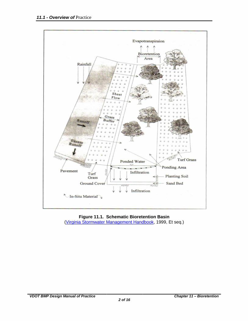
11.1 Overview of Practice Bioretention practices form a class of BMP whose primary function is to improve the quality of stormwater runoff by means of adsorption, filtration, volitization, ion exchange, and microbial decomposition. However, some runoff rate and volume reduction is observed through the infiltration of runoff. In the most general sense, a bioretention BMP can be thought of as a modified infiltration area comprised of a specific mix of trees, plants, and shrubs intended to mimic the ecosystem of an upland (non-wetland) forest floor. There are two categories of bioretention BMP: basins and filters. Bioretention basins are planting areas constructed as shallow basins in which stormwater inflow is treated by filtration through the surface plant material, biological and chemical reactions within the soil and basin vegetation, and the eventual infiltration into the underlying soil media. Bioretention filters function much the same as bioretention basins, but are used in locations where full infiltration is not feasible due to inadequate soil permeability or the proximity to wells, drainfields, or structural foundations. Bioretention filters are equipped with a connection to a local storm sewer system such that water enters the storm sewer after it has filtered through the bioretention cell. Figures 11.1 and 11.2 present the general configuration of a bioretention basin and filter. The designer is also referred to Figures 3.11-2 – 3.11-5 of the Virginia Stormwater Management Handbook (DCR, 1999, Et seq., Et seq.) for location and conceptual layout suggestions for bioretention facilities. Yu (2004) states that bioretention units can be applied in treating stormwater runoff from VDOT facilities such as weigh stations, park-and-ride facilities, and welcome stations. Other possible application scenarios include rooftop runoff and runoff from short stretches of roadway. Because of their use of specific vegetative plantings and landscaping techniques, bioretention BMPs can provide significant aesthetic benefit to a developed site.
11.1 - Overview of Practice
VDOT BMP Design Manual of Practice
2 of 16
Chapter 11 – Bioretention
Figure 11.1. Schematic Bioretention Basin (Virginia Stormwater Management Handbook, 1999, Et seq.)

11.1 - Overview of Practice
VDOT BMP Design Manual of Practice
3 of 16
Chapter 11 – Bioretention
Figure 11.2. Schematic Bioretention Filter (Virginia Stormwater Management Handbook, 1999, Et seq.)

11.2 - Site Constraints and Siting of the Facility
VDOT BMP Design Manual of Practice 4 of 16
Chapter 11 – Bioretention
11.2 Site Constraints and Siting of the Facility When a bioretention facility is proposed the designer must consider a number of site constraints in addition to the contributing drainage area’s impervious cover. These constraints are discussed as follows. 11.2.1 Minimum Drainage Area
The minimum drainage area contributing runoff to a bioretention cell is not restricted. However, the cost associated with constructing and maintaining a bioretention facility typically limits its use to drainage areas of at least 0.25 acres. Bioretention basins and filters are particularly well suited to small drainage areas. 11.2.2 Maximum Drainage Area
The maximum drainage area to a single bioretention facility should be restricted to no more than one acre. 11.2.3 Site Slopes
Bioretention facilities are suitable for installation on sites exhibiting average slopes less than 20 percent. Bioretention practices should be located a minimum of 50 feet away from any slope steeper than 15 percent. When average site slopes exceed 20 percent, alternative BMP measures should be considered. 11.2.4 Site Soils
This section refers to the native site soils underlying a bioretention facility. The planting soil mix of a bioretention facility is governed by specific guidelines discussed later in this chapter and also in the Virginia Stormwater Management Handbook (DCR, 1999, Et seq.). Soil infiltration rate is a critical design element in a bioretention basin. When such a facility is proposed, a subsurface analysis and permeability test is required. The required subsurface analysis should investigate soil characteristics to a depth of no less than three feet below the proposed bottom of the engineered media. Data from the subsurface investigation should be provided to the Materials Division early in the project planning stages to evaluate the feasibility of such a facility on native site soils. The soil infiltration rate should be measured when the soil is in a saturated condition. Soil infiltration rates which are deemed acceptable for bioretention facilities range between 0.52 and 8.27 inches per hour. Infiltration rates falling within this range are typically exhibited by soils categorized as loam, sandy loam, and loamy sand. Soils exhibiting a clay content of greater than 30 percent are unacceptable for bioretention facilities. Similarly, soils exhibiting extremely high infiltration rates, such as some types of sand, should also be avoided. Table 11.1 presents typical infiltration rates observed for a variety of soil types. This table is provided as a reference only, and does not replace the need for a detailed site soil survey.

11.2 - Site Constraints and Siting of the Facility
VDOT BMP Design Manual of Practice
5 of 16
Chapter 11 – Bioretention
Table 11.1. Hydrologic Soil Properties Classified by Soil Texture
Source: Virginia Stormwater Management Handbook, (DCR, 1999, Et seq.) 11.2.5 Depth to Water Table Bioretention basins should not be installed on sites with a high groundwater table. Inadequate separation between the BMP bottom and the surface of the water table may result in contamination of the water table. This potential contamination arises from the inability of the soil underlying the BMP to filter pollutants prior to their entrance into the water table. Additionally, a high water table can flood the bioretention cell and render it inoperable during periods of high precipitation and/or runoff. A separation distance of no less than two feet is required between the bottom of a bioretention basin and the surface of the seasonally high water table. Unique site conditions may arise which require an even greater separation distance. Bioretention filters (Figure 11.2) may be considered for use on sites where a high groundwater table prohibits the use of a bioretention basin. 11.2.6 Separation Distances Bioretention basins should be located at least 20 feet down-slope and at least 100 feet up-slope from building foundations. Bioretention basins should not be located within 100 feet of any water supply well. Local health officials should be consulted when the implementation of a bioretention basin is proposed within the vicinity of a septic drainfield. Generally, bioretention filters should be considered over bioretention basins for implementation in the vicinity of water supply wells, septic drainfields, and structural foundations. This is because bioretention filters provide conveyance of runoff by the local storm sewer upon percolation through the filter media, whereas bioretention basins infiltrate runoff to the surrounding subsoil.

11.2 - Site Constraints and Siting of the Facility
VDOT BMP Design Manual of Practice
6 of 16
Chapter 11 – Bioretention
11.2.7 Bedrock A minimum of two feet of separation is required between the bottom of a bioretention basin and bedrock, with four feet or greater recommended. 11.2.8 Placement on Fill Material Bioretention basins should not be constructed on or nearby fill sections due to the possibility of creating an unstable subgrade. Fill areas are vulnerable to slope failure along the interface of the in-situ and fill material. The likelihood of this type of failure is increased when the fill material is frequently saturated, as anticipated when a bioretention basin. 11.2.9 Karst The concentration of runoff into a bioretention basin may result in the formation of flow channels. Such channels may lead to collapse in karst areas, and therefore the implementation of bioretention basins in known karst areas should be avoided. 11.2.10 Existing Utilities Bioretention facilities can often be constructed over existing easements, provided permission to construct the strip over these easements is obtained from the utility owner prior to design of the strip. 11.2.11 Wetlands When the construction of a bioretention facility is planned in the vicinity of known wetlands, the designer must coordinate with the appropriate local, state, and federal agencies to identify wetlands boundaries, their protected status, and the feasibility of BMP implementation in their vicinity. 11.2.12 Perennial and Chlorinated Flows Bioretention facilities must not be subjected to continuous or very frequent flows. Such conditions will lead to anaerobic conditions which support the export of previously captured pollutants from the facility. Additionally, bioretention facilities must not be subjected to chlorinated flows, such as those from swimming pools or saunas. The presence of elevated chlorine levels can kill the desirable bacteria responsible for the majority of nitrogen uptake in the facility.

11.3 - General Design Guidelines
VDOT BMP Design Manual of Practice
7 of 16
Chapter 11 – Bioretention
11.3 General Design Guidelines The following presents a collection of design issues to be considered when designing a bioretention facility for improvement of water quality. 11.3.1 Facility Location When the proposed bioretention facility is to receive runoff in the form of sheet flow, the overall grading of the site must direct all runoff to the facility prior to its leaving the site or entering a downstream conveyance system. Consequently, the proposed location of a bioretention facility must be established early in the project design phase and remain an integral component of the site design throughout. 11.3.2 Basin Size The minimum floor area of a bioretention facility is a function of the water quality volume (WQV) to be treated from the facility’s contributing drainage area. Table 11.2 shows the minimum bioretention floor areas as a function of WQV.
Bioretention Floor Area WQV 2.5% of Contributing Impervious Area 0.5 Inches Over Impervious Area 4.0% of Contributing Impervious Area 1.0 Inches Over Impervious Area
Table 11.2. Minimum Bioretention Floor Area
Source: Virginia Stormwater Management Handbook, (DCR, 1999, Et seq.)
The minimum size for any bioretention facility should be 10 feet wide (perpendicular to incoming sheet flow direction) and 15 feet long. 11.3.3 Basin Depth The depth of the facility’s planting soil (reference Figure 11.1) should be approximately 30 inches, or the diameter of the largest plant root ball plus 4 inches. 11.3.4 Surface Ponding Depth The depth of ponding on the facility surface should be restricted to no more than 6 inches to preclude the development of anaerobic conditions within the planting soil. 11.3.5 Design Infiltration Rate To provide a factor of safety, and to account for the decline in performance as the facility ages, the soil infiltration rate upon which a bioretention basin design is founded should be one-half the infiltration rate obtained from the geotechnical analysis. 11.3.6 Runoff Pretreatment Bioretention facilities must be preceded upstream by some form of runoff pretreatment. Roadways and parking lots often produce runoff with high levels of sediment, grease, and oil. These pollutants can potentially clog the pore space in the facility, thus greatly reducing its pollutant removal performance. The selection of runoff pretreatment is primarily a function of the type of flow entering the facility, as disused below.

11.3 - General Design Guidelines
VDOT BMP Design Manual of Practice
8 of 16
Chapter 11 – Bioretention
Runoff entering a bioretention basin or filter as sheet flow may be treated by a grass filter strip. The purpose of the grass buffer strip/energy dissipation area is to reduce the erosive capabilities of runoff prior to its entrance into the bioretention area. The recommended length of the grass buffer strip is a function of the land cover of the contributing drainage area and its slope. Under no circumstance should the grass buffer strip be less than 10 ft. The following table provides guidance in sizing the grass buffer strip leading to the bioretention area:
Table 11.3. Design Parameters for Grass Buffer Pretreatment
Source: Virginia Stormwater Management Handbook, (DCR, 1999, Et seq.) Flow may enter the bioretention facility in a concentrated flow regime. In such cases, a common pretreatment method is to pass the incoming flow through a grass-lined channel equipped with a pea gravel diaphragm prior to its entrance into the bioretention area. The recommended length of the grass swale is a function of the land cover of the contributing drainage area and its slope. When used as pre-treatment for bioretention facilities, grass swales should be at least 20 feet in length. The following table provides guidance in sizing the grass swale leading to the bioretention area:
Table 11.4. Design Parameters for Grass Swale Pretreatment
Source: Virginia Stormwater Management Handbook, (DCR, 1999, Et seq.)
11.3.7 Offline Configurations Whenever possible, bioretention facilities should be placed off-line so that flow is diverted onto it. This permits the facility to fill with only the desired treatment volume and bypass any remaining flow to the storm drainage system. Because offline bioretention BMPs are sized to accommodate only the designated water quality volume, a flow-splitter or diversion weir must be designed to restrict inflows to the bioretention area.

11.3 - General Design Guidelines
VDOT BMP Design Manual of Practice
9 of 16
Chapter 11 – Bioretention
The flow-splitter or diversion weir must be designed to admit a designated volume of runoff into the basin rather than to simply regulate the flow rate into the basin. The diversion structure may be prefabricated, or cast in place during construction. A schematic illustration of the flow-splitting weir is shown as follows:
Figure 11.3. Flow-splitting Diversion Weir (Bell, Warren, 1993)
Typically, the construction of the diversion weir will place its crest elevation equal to the maximum allowable ponding depth in the bioretention area (6 inches for bioretention basins and 12 inches for bioretention filters). Flow over the diversion weir will occur when runoff volumes exceed the computed water quality volume. These overflows then enter the stormwater conveyance channel. This configuration results in minimal mixing of the held water quality volume with flows from large runoff producing events in excess of this volume. A modified design referred to as a dual pond system is characterized by a diversion weir which directs the computed water quality volume into the bioretention area, while conveying excess volumes downstream to a peak mitigation detention pond. 11.3.8 Overflow/Bypass Structure When a bioretention facility is constructed online, or the maximum volume of flow entering the facility is not otherwise restricted, an overflow structure must be provided. This structure provides bypass for excess runoff when the bioretention subsurface and surface capacity is met. Common overflow structures include domed risers, grate or slot inlets, and weir structures. Budget, site aesthetics, and maintenance will govern the selection of the overflow structure. The sizing of the overflow structure must consider the flow rate for the design storm of interest, typically the 10-year runoff producing event. The crest or discharge elevation of the overflow structure should be set an elevation of 6 inches above the mulch layer of the bioretention bed. When designed as a bioretention filter, and equipped with an underdrain system, the crest of the overflow may be set at
Water Quality Volume

11.3 - General Design Guidelines
VDOT BMP Design Manual of Practice
10 of 16
Chapter 11 – Bioretention
an elevation as much as one foot above the mulch layer of the facility. Typical domed riser overflow structures are shown in Figure 11.4.
Figure 11.4. Typical Domed Riser Bypass Structure Configuration (PADEP, 2006)
11.3.9 Planting Considerations The ultimate goal in the selection and location of vegetation within a bioretention facility is to, as closely as possible, mimic an upland (non-wetland) terrestrial forest ecosystem. This type of planting scheme is based on a natively-occurring forest’s ability to effectively cycle and assimilate nutrients, metals, and other pollutants through the plant species, underlying soil, and also the system’s organic matter. Of additional concern in the selection of vegetative planting species is aesthetics. Bioretention BMPS can often be incorporated into the stormwater management plans of high profile areas, providing a desirable site amenity in the form of landscaping. The design of bioretention facilities requires a working knowledge of indigenous horticultural practices, and it is recommended that a landscape architect or other qualified professional participate in the design process. The Virginia Stormwater Management Handbook (DCR, 1999, Et seq.) provides a list of species suitable for inclusion in a bioretention facility. These species can be found in Tables 3.11-7A – 3.11-7C of the handbook. Species included have been deemed suitable based on their ability to tolerate pollutant loading, soil moisture fluctuations, and frequent inundation. Species not included in these tables should not be selected because they are not capable of surviving the conditions anticipated in a bioretention facility and/or they do not provide a desired level of pollutant uptake. A minimum of three different species of trees and three different species of shrubs should be selected for each individual bioretention facility. Such diversity in species selection assists in reducing monoculture mortality concerns as well as providing a constant and predictable level of evapotranspiration and pollutant uptake. The ratio of shrubs to trees should range between 2:1 and 3:1. A general guideline for determining the number of individual plantings required for a given bioretention area is 1,000 individual stems per planted acre. Table 11.5 provides average, maximum, and minimum planting guidelines as well as spacing recommendations.

11.3 - General Design Guidelines
VDOT BMP Design Manual of Practice
11 of 16
Chapter 11 – Bioretention
Table 11.5. Recommended Tree and Shrub Spacing
Source: Virginia Stormwater Management Handbook, (DCR, 1999, Et seq.) The Virginia Stormwater Management Handbook (DCR, 1999, Et seq.) provides a full discussion on the desirable planting soil and mulch layer characteristics of a bioretention facility in Minimum Standard 3.11. The planting soil of a bioretention facility should exhibit a pH ranging between 5.5 and 6.5 and a clay content of no greater than 5 percent.

11.4 - Design Process
VDOT BMP Design Manual of Practice 12 of 16
Chapter 11 – Bioretention
11.4 Design Process This section presents the design process applicable to bioretention facilities serving as water quality BMPs. The pre and post-development runoff characteristics are intended to replicate stormwater management needs routinely encountered on VDOT facilities projects. The hydrologic calculations and assumptions presented in this section serve only as input data for the detailed BMP design steps. Full hydrologic discussion is beyond the scope of this report, and the user is referred to Chapter 4 of the Virginia Stormwater Management Handbook (DCR, 1999, Et seq.) for details on hydrologic methodology. The bioretention basin design will meet the technology-based water quality requirements arising from construction of a Park-and-Ride facility located in York County. Site grading is such that runoff from the facility’s parking lot is directed onto the bioretention area through a curb cut along the parking lot’s downstream edge. This example is an online configuration, and therefore the facility must be equipped with a bypass for flows exceeding the storage capacity of the bioretention cell. The total project site, including right-of-way and all permanent easements, consists of 1.34 acres. Pre and post-development land cover and hydrologic characteristics are summarized below in Tables 11.6 and 11.7. Geotechnical investigations reveal the saturated soil infiltration rate to be 1.8 inches per hour. The project site does not exhibit a high or seasonally high groundwater table. Pre-Development Post-Development Project Area (acres) 1.34 1.34 Land Cover Unimproved Grass Cover 0.83 acres impervious cover Impervious Percentage 0 62
Table 11.6. Hydrologic Characteristics of Example Project Site
York County - 10 Year
Rainfall Constants
Acreage Rational
C A B
tc (min)
i10 (iph)
Q10 (cfs)
0.83 0.9 186.78 21.22 8 6.39 4.8
Table 11.7. Peak Parking Lot Runoff
Step 1. Compute the Required Water Quality Volume The project site’ water quality volume is calculated as one half inch over the developed Impervious Area. This basic water quality volume is computed as follows:
ft
in
inIAWQV
12
21
IA= impervious area (ac.)

11.4 - Design Process
VDOT BMP Design Manual of Practice 13 of 16
Chapter 11 – Bioretention
The project site in this example has a total drainage area of 1.34 acres. The total impervious area within the site is 0.83 acres. Therefore, the water quality volume is computed as follows:
3
2
506,112
560,432183.0
ft
ft
inac
ftinac
WQV
Step 2. Compute the Minimum Basin Floor Area The minimum allowable bioretention surface area is a function of the site’s water quality volume. The water quality volume in this example was based on one-half inch of runoff from the site’s impervious cover. Therefore, referencing Table 11.2, the minimum floor area of the facility is 2.5 percent of the contributing impervious cover, computed as follows:
22
904025.0560,4383.0 ftac
ftacArea
The minimum dimensions of a bioretention facility should be 10 feet wide (perpendicular to the incoming flow direction) and 15 feet long. The actual length to width ratio of the facility as well as its overall geometric configuration is determined by various site constraints such as topography and available area. In this example, we will employ a length to width ratio of 1.5:1. Therefore, the approximate dimensions of the facility are computed as follows:
ftL
ftW
ftWW
ftWL
WL
375.24
9045.1904
5.1
2
2
For bioretention areas with a preliminary computed length of greater than 20 feet, the actual design length should be twice that which ensures dispersal of incoming sheet flow. The following steps illustrate the process for evaluating whether or not the preliminary computed length must be increased to meet this requirement. The bioretention area will be preceded upstream by pretreatment in the form of a grass filter strip. Runoff will leave the proposed parking lot through a curb cut, and then discharge onto the filter strip after passing over a level spreader. The size of the level spreader is a function of the 10-year flow from the contributing drainage area. The required level spreader dimensions are shown in Table 11.8.

11.4 - Design Process
VDOT BMP Design Manual of Practice
14 of 16
Chapter 11 – Bioretention
Q10 (cfs)
Depth (ft)
Width of Lower Side
Slope of Spreader
(ft)
Length (ft)
0-10 0.5 6 10 20-10 0.6 6 20
Table 11.8. Minimum Level Spreader Dimensions
Source: Virginia Erosion and Sediment Control Handbook (DCR, 1992)
The 10-year peak rate of runoff from the roadway is 4.8 cfs (see Table 11.7). Therefore, the minimum level spreader “lip” length that will discharge runoff onto the strip is 10 feet. The chosen bioretention length of 37 feet is more than twice the level spreader length of 10 feet discharging sheet flow onto the grass filter strip, and is therefore acceptable. Step 3. Specify Bioretention Depth The depth of the facility’s planting soil should be approximately 30 inches, or the diameter of the largest plant root ball plus 4 inches. Site grading and placement of the facility’s overflow structure must ensure a maximum surface ponding depth of 6 inches. Step 4. Design Overflow Structure An overflow structure must be provided for large runoff producing events to bypass excess runoff when the bioretention surface and subsurface storage capacity is exceeded. The crest/outflow of the bypass system should be set at an elevation 6 inches above the surface of the bioretention floor. This will ensure discharge through the bypass system only when the design parameters of the bioretention area have been exceeded. Common overflow structures include domed risers, grate or slot inlets, and weir structures. The overflow/bypass system will function as a conventional storm sewer system when the facility’s planting soil is saturated and a ponding depth of 6 inches is observed on the surface of the facility. Therefore, the bypass system should be designed to carry a peak 10-year flow rate of 4.8 cfs (reference Table 11.7). The bypass system must discharge into an adequate receiving channel as defined by Regulation MS-19 in the Virginia Erosion and Sediment Control Handbook, (DCR, 1992). Existing natural channels conveying pre-development flows may be considered receiving channels if they satisfactorily meet the standards outlined in the VESCH MS-19. Unless unique site conditions mandate otherwise, receiving channels should be analyzed for overtopping during conveyance of the 10-year runoff producing event and for erosive potential under the 2-year event. Sizing of the bypass pipe is accomplished by use of the Manning equation shown below:
21
3249.1 SAR
nQ h ⋅⋅=

11.4 - Design Process
VDOT BMP Design Manual of Practice
15 of 16
Chapter 11 – Bioretention
A typical Manning’s n value for reinforced concrete pipe is 0.013. For a fixed discharge, Q, the minimum required diameter, D, of a circular pipe flowing full can be computed by the following equation:
375.0
21
))((16.2
=
S
nQD
D = minimum pipe diameter (ft) Q = pipe discharge (cfs) N = Manning’s roughness coefficient S = pipe slope (ft/ft)
Assuming a slope of 1.5 percent on the overflow pipe, we compute the minimum pipe diameter required to convey the facility’s 10-year runoff as:
( ) inchesftD 5.1204.1015.0
)013.0)(8.4(16.2375.0
21 ==
=
The bypass pipe shall be 15 inches in diameter. The 15” bypass pipe shall connect to a conventional stormwater conveyance system and/or carry runoff volumes in excess of the water quality volume to an adequate receiving channel. Step 5. Specify Number of Vegetative Plantings A typical bioretention facility should be planted with approximately 1,000 stems per acre. This vegetation should be comprised of both shrubs and trees, with a shrub to tree ratio ranging between 2:1 and 3:1. A minimum of three different species of trees and three different species of shrubs should be specified, with specific plant species determined from Tables 3.11-7A – 3.11-7C of the Virginia Stormwater Management Handbook (DCR, 1999, Et seq.). Employing a 2.5:1 shrub to tree ratio, the number of shrubs and trees for the proposed bioretention area is determined as follows:
Total bioretention area: acft
acftft 02.0560,431375.24 2 =××
Total number of stems: 20000,102.0 =×ac
stemsac
Total number of shrubs (s): s = 2.5 x # trees Total number of trees (t): 7.5205.2 =⇒=+ ttt

11.4 - Design Process
VDOT BMP Design Manual of Practice
16 of 16
Chapter 11 – Bioretention
The bioretention area should be planted with 6 trees, 2 each from three different species. Additionally, a total of 15 shrubs should be planted, 5 each from three different species. Step 6. Provide for Runoff Pretreatment Runoff entering the proposed bioretention cell will pass through an upstream grass filter strip serving the purpose of pretreating the incoming runoff. Sizing of this filter strip is based on Table 11.3. The slope of the filter strip will be approximately 1.5 percent and the maximum flow path across the impervious parking lot is 75 feet. Obtained from Table 11.3, these parameters require a filter strip length of 20 feet. Alternative Design – Bioretention Filter Bioretention filters provide water quality improvement in essentially the same manner as bioretention basins, but are used in locations where full infiltration is not feasible either due to inadequate soil permeability or the proximity to wells, drainfields, or structural foundations. Bioretention filters are equipped with a connection to the site’s storm sewer system such that water enters the storm sewer after it has filtered through the bioretention cell (see Figure 11.2). The same sizing and design parameters apply to bioretention filters as apply to bioretention basins, with the exception of maximum surface ponding depth. Because runoff filters through a bioretention filter more quickly than through a bioretention basin, the maximum surface ponding depth may be increased to 12 inches. When a bioretention filter is chosen due to the proximity of the facility to wells, structural foundations, or septic drainfields, the entire basin must be underlain by a synthetic liner as approved by the Materials Division. When the selection of a bioretention filter arises due to inadequately low percolation rates of the site’s native soils, the synthetic membrane may be omitted.