chapter 10: standards for the provision of … · mos part 172—air traffic services chapter 10:...
TRANSCRIPT

MOS Part 172—Air Traffic Services Chapter 10:Standards for the Provision of Air Traffic Services
Version 1.3: April 2006 10-1
CHAPTER 10: STANDARDS FOR THE PROVISION OF AIR TRAFFIC SERVICES
Section 10.1: General
10.1.1 Purpose 10.1.1.1 This Chapter contains the standards, rules and procedures for the provision
of air traffic services that are additional to, or expand upon, or specify additional conditions for, the standards, rules and procedures contained in ICAO Annex 11, PANS-OPS Volume II, ICAO Doc 8168, ICAO Doc 7030 and ICAO PANS-ATM Doc 4444.
10.1.2 Air Traffic Services Commensurate with Airspace Classification 10.1.2.1 Unless otherwise authorised by CASA, air traffic services must be provided
commensurate with the airspace classifications as notified in the AIP.
10.1.3 Traffic Priorities 10.1.3.1 Aircraft in a state of emergency must be given priority over all other traffic.

Chapter 10: Standards for the Provision of Air Traffic Services
MOS Part 172—Air Traffic Services
10-2 Version 1.3: April 2006
Intentionally Blank

MOS Part 172—Air Traffic Services Chapter 10:Standards for the Provision of Air Traffic Services
Version 1.3: April 2006 10-3
Section 10.2: ATS Surveillance Systems
10.2.1 Use of ADS-B Surveillance 10.2.1.1 ADS-B may be used alone, or in combination with radar, for the provision of
air traffic services if: (a) reliable ADS-B coverage exists in the area; and (b) identification of ADS-B equipped aircraft is established and maintained;
and (c) the ADS-B data indicates that:
(i) the HPL does not exceed 0.5 NM; and (ii) the probability of the HPL information being erroneous is less than
1 × 10⁻⁵ per flight hour.
Note: These values are equivalent to a NUC_P of 5 as defined in ICAO Annex 10, Volume III, Part 1, Chapter 5, Appendix, or a NIC of 6 and a SIL of 2 as defined in RTCA DO-260A.
10.2.2 Operation of ADS-B Transmitters 10.2.2.1 If the situation display shows that the aircraft identification transmitted by an
ADS-B-equipped aircraft is different from that expected from the aircraft, ATC must ask the pilot to confirm aircraft identification.
10.2.2.2 If, after a pilot has been instructed to operate the aircraft’s ADS-B transmitter on an assigned aircraft identification or to change call sign, the aircraft identification shown on the situation display is different from that assigned to the aircraft, ATC must ask the pilot to re-enter the assigned aircraft identification.
10.2.2.3 If the identification of an aircraft as shown on the situation display is different from that assigned to the aircraft, and a request under subsection 10.2.2.2 has not resolved the discrepancy, ATC must ask the pilot to confirm that the correct aircraft identification has been selected.
10.2.2.4 If the discrepancy continues following confirmation by the pilot that the correct aircraft identification has been set on the ADS-B identification feature, ATC must: (a) tell the pilot of the persistent discrepancy; and (b) if possible, correct the label showing the aircraft identification on the
situation display; and (c) tell the next control position and any other interested unit using ADS-B
for identification purposes of the erroneous aircraft identification transmitted by the aircraft.

Chapter 10: Standards for the Provision of Air Traffic Services
MOS Part 172—Air Traffic Services
10-4 Version 1.3: April 2006
10.2.3 Verification of Level Information 10.2.3.1 The tolerance value for pressure altitude-derived level information displayed
to the controller is ±200 ft. Geometric height information must not be used for separation.
10.2.3.2 ATC must verify displayed pressure altitude-derived level information: (a) on initial contact with an aircraft or, if this is not feasible, as soon as
possible after initial contact; and (b) by simultaneous comparison with:
(i) altimeter-derived level information received from the same aircraft by radiotelephony; or
(ii) at an aerodrome — the aerodrome elevation during the take-off roll, if the level information subsequently indicates a positive climb after take-off.
10.2.3.3 If aircraft pressure altitude-derived level information is within the approved tolerance value, the pilot need not be advised of the verification. Geometric height information must not be used to determine if altitude differences exist.
10.2.3.4 If the displayed level information is not within the approved tolerance value or if a discrepancy greater than the approved tolerance value is detected after verification, ATC must tell the pilot of this and ask the pilot to check the pressure setting and confirm the aircraft’s level.
10.2.3.5 If the discrepancy continues to exist after confirmation of the correct pressure setting, ATC must: (a) ask the pilot to stop Mode C or ADS-B altitude data transmission, if this
does not cause the loss of position and identity information, and tell the next control position or ATC unit for the aircraft of the action taken; or
(b) tell the pilot of the discrepancy and ask that the operation continue in order to prevent loss of position and identity information of the aircraft, if possible, override the label displayed level information with the reported level and tell the next control position or ATC unit for the aircraft of the action taken.
10.2.4 Determination of Level Occupancy Using ATS Surveillance System-derived Level Information
10.2.4.1 Aircraft maintaining a level. An aircraft is taken to be maintaining its assigned level as long as the pressure altitude-derived level information indicates that it is within ±200 ft of the assigned level.
10.2.4.2 Aircraft vacating a level. An aircraft cleared to leave a level is taken to have commenced its manoeuvre and vacated the previously occupied level when the pressure altitude-derived level information indicates a change of 400 ft or more in the anticipated direction from its previously assigned level.

MOS Part 172—Air Traffic Services Chapter 10:Standards for the Provision of Air Traffic Services
Version 1.3: April 2006 10-5
10.2.4.3 Aircraft passing a level in climb or descent. An aircraft in climb or descent is taken to have passed a level when the pressure altitude-derived level information indicates that it has passed this level in the required direction by 400 ft or more.
10.2.4.4 Aircraft reaching a level. An aircraft is taken to have reached the level to which it has been cleared when the greater of 3 consecutive renewals of display updates or at least 15 seconds have passed since the pressure altitude-derived level information indicated that it was within ±200 ft of the assigned level.
10.2.5 Establishment of Identification 10.2.5.1 If SSR or PSR is used for identification, aircraft must be identified by at least
1 of the following procedures: (a) application of 1 or more of the SSR or PSR identification procedures
specified in PANS-ATM; (b) correlating a particular radar position to the position of an aircraft
observed visually. 10.2.5.2 If ADS-B is used for identification, aircraft must be identified by at least 1 of
the following procedures: (a) direct recognition of the aircraft identification in an ADS-B label; (b) transfer of ADS-B identification (see subsection 12.1.7); (c) observation of compliance with an instruction to TRANSMIT ADS-B
IDENT.
10.2.6 Position Information 10.2.6.1 ATC must tell the pilot of an aircraft provided with ATS surveillance service of
its position in the following circumstances: (a) on identification, unless the identification is established:
(i) based on the pilot’s report of the aircraft position, or within 1 NM of the runway on departure, if the observed position on the situation display is consistent with the aircraft’s time of departure; or
(ii) by use of ADS-B aircraft identification, SSR Mode S aircraft identification or assigned discrete SSR codes if the location of the observed position indication is consistent with the current flight plan of the aircraft; or
(iii) by transfer of identification (see subsection 12.1.7); (b) when the pilot requests this information; (c) when the pilot’s estimate differs significantly from the controller’s
estimate based on the observed position;

Chapter 10: Standards for the Provision of Air Traffic Services
MOS Part 172—Air Traffic Services
10-6 Version 1.3: April 2006
(d) when the pilot is instructed to resume own navigation after vectoring if the current instructions had diverted the aircraft from a previously assigned route;
(e) immediately before termination of ATS surveillance service, if the aircraft is observed to deviate from its intended route.
10.2.7 Use of Speed Control 10.2.7.1 Speed Control must not be applied to formation flights or fuel critical flights.
10.2.8 Termination of ATS Surveillance Services 10.2.8.1 When an aircraft exits controlled airspace into an area in which ATS
surveillance services will continue, ATC must inform the pilot accordingly.
10.2.9 Obstacle Clearance 10.2.9.1 When vectoring, ATC must provide at least 1 000 ft vertical clearance over
any obstacle within: (a) 3 NM of the aircraft when the range scale in not greater than 50 NM; or (b) 5 NM of the aircraft when the range scale is greater than 50 NM.
10.2.9.2 These obstacle clearance requirements do not apply: (a) when vectoring as part of an issued SID; or (b) when ATC authorises a visual departure; or (c) in VMC by day only, when ATC assigns responsibility for arranging
obstacle clearance specifically to the pilot; or (d) when conducting a Radar Cloud Break Procedure.
10.2.10 Surveillance Radar Approach (SRA) Procedures 10.2.10.1 For civil aircraft, Surveillance Radar Approach Procedures, as specified in
ICAO PANS-ATM are not authorised, unless by pilot request, or in the case of emergency.
10.2.11 Vectoring Special VFR 10.2.11.1 Special VFR aircraft may be vectored only if warranted by emergency
conditions.
10.2.12 Issuing ATS Surveillance System Derived Distance 10.2.12.1 ATS surveillance system derived distance and appropriate altitude
assignments may be issued to an arriving aircraft using a track for which a DME or GPS Arrival procedure is specified, if: (a) DME is not available; or (b) a pilot conducting a GPS arrival reports the loss of RAIM.

MOS Part 172—Air Traffic Services Chapter 10:Standards for the Provision of Air Traffic Services
Version 1.3: April 2006 10-7
10.2.12.2 When ATS surveillance system derived distances are used as a substitute for DME or GPS derived distance information, the reference datum being used for the distance information (e.g. DME site) must be displayed on the situation display map.
10.2.13 Radar Cloud Break Procedure 10.2.13.1 The radar cloud break procedures may only be applied to non-military aircraft
at Sydney, Melbourne, Essendon, Brisbane, Adelaide and Perth provided that: (a) the requirements in Table 10.2-1 associated with the applicable flight
conditions are complied with; (b) the aircraft is in direct communication with the radar controller; (c) the radar range from the aerodrome is decreasing; (d) radar–derived ranges are passed with the descent instructions; and (e) reduction of normal terrain clearance standards associated with these
procedures is within 10 NM of the aerodrome. 10.2.13.2 The altitude assigned to aircraft between 10 NM and 4 NM radar range from
the aerodrome must not be more than 500 FT below the minimum altitude, in accordance with the Radar Vectoring and Terrain Clearance standards specified earlier in this part.
10.2.13.3 Radar cloud break procedures must not be used: (a) on tracks for which a DME arrival procedure is prescribed; (b) to runways served by an instrument approach aid providing a straight-
in approach procedure. Table 10.2-1
Flight conditions Requirements
Visual flight is certain at or above altitude assigned assigned in accordance with paragraph 10.2.13.1(e) above.
1. The reported cloud base in the applicable sector is at least 300 FT above the assignable altitude (e.g. in a 2,000 FT minimum altitude sector where descent to 1,500 FT is permissible, the cloud base must be at or above 1,800 FT);
2. The aircraft is on a radar heading which will cause it to pass within 3 NM of the centre of the aerodrome as shown on the radar map.
(Contd.)

Chapter 10: Standards for the Provision of Air Traffic Services
MOS Part 172—Air Traffic Services
10-8 Version 1.3: April 2006
Flight conditions Requirements
Visual flight is probable at or above altitude assigned in accordance with paragraph 10.2.13.1 (e) above, but is certain after further descent clearance to the prescribed minimum altitude at 4 NM range from the aerodrome.
3. The reported cloud base in the applicable sector is at the assignable altitude, between the assignable altitude and 300 FT above it (e.g. in a 2,000 FT minimum altitude sector where descent to 1,500 FT is permissible, the cloud base must be at least 1,500 FT or between 1,500 FT and 1,800 FT);
4. The procedure is applied to DME-equipped aircraft only;
5. The aircraft is on a radar heading which will cause it to pass within 3 NM of the centre of the aerodrome as shown on the radar map, but after passing 4 NM the aircraft must be on a radar heading which will cause it to track directly towards the centre of the aerodrome;
6. A ‘LOSS OF COM’ procedure is issued with the initial descent instructions at 10 NM.
Visual flight is not possible at altitude assigned in accordance with paragraph 10.2.13.1 (e) above, and is not possible until at or above prescribed minimum altitude after a further descent clearance is issued at 4 NM radar range from the aerodrome.
1. The reported cloud base in the applicable sector is at the prescribed minimum altitude, or between the prescribed minimum altitude, and the assigned altitude;
2. The procedure is applied to DME-equipped aircraft only;
3. The aircraft is on a radar heading which will cause it to pass within 3 NM of the centre of the aerodrome as shown on the radar map, but after passing 4 NM the aircraft must be on a radar heading which will cause it to track directly towards the centre of the aerodrome, or is established on the extended runway centre-line before reaching 4 NM;
4. The aircraft is instructed to report at 4 DME when the initial descent instruction is issued at 10 NM;
5. A ‘LOSS OF COM’ procedure is issued with the initial descent instructions at 10 NM.

MOS Part 172—Air Traffic Services Chapter 10:Standards for the Provision of Air Traffic Services
Version 1.3: April 2006 10-9
Section 10.3: Circuits and Runways
10.3.1 Selection of Runway in Use 10.3.1.1 Use of other than nominated runways. Controllers must not nominate a
particular runway for use if an alternative runway is available, when: (a) for runway conditions that are completely dry:
(i) the cross-wind component, including gusts, exceeds 20 KT; (ii) the downwind component, including gusts, exceeds 5 KT.
(b) for runway conditions that are not completely dry; (i) the cross-wind component, including gusts, exceeds 20 KT; (ii) there is a downwind component.
10.3.1.2 Authorising intersection departures. A controller may authorise a departure from a runway intersection when requested by the pilot or may offer an intersection departure to assist traffic flow. The pilot must be advised of the remaining runway length if such information is not readily available to the pilot.
10.3.2 Simultaneous Parallel Runway Operations 10.3.2.1 The procedures in this part must not be used at GAAP aerodromes. 10.3.2.2 In addition to ICAO PANS-ATM applications, parallel runways may be used
for Simultaneous Opposite Direction Operations (SODPROPS) (see paragraph 10.4.8).
10.3.2.3 Whenever parallel runway operations are in progress, pilots must be notified by inclusion of such advice and an expectation of the type of approach or departure on the ATIS.
10.3.2.4 The use of SODPROPS must be broadcast on the ATIS including the runway configuration being used for the procedure.

Chapter 10: Standards for the Provision of Air Traffic Services
MOS Part 172—Air Traffic Services
10-10 Version 1.3: April 2006
Intentionally Blank

MOS Part 172—Air Traffic Services Chapter 10:Standards for the Provision of Air Traffic Services
Version 1.3: April 2006 10-11
Section 10.4: Departures and Arrivals
10.4.1 Arriving Aircraft 10.4.1.1 To provide for the possibility of radio failure, aircraft under procedural control,
cleared to the same holding point or holding points not laterally separated, must not be assigned the same level while flying within 10 MIN of the holding point. However, this requirement does not preclude two arriving aircraft on laterally separated flight paths, which are at least 90 degrees apart, being: (a) cleared to make simultaneous visual approaches; or (b) instructed to descend visually to the coordinated common level or
different levels when, due to traffic, a visual approach cannot be made provided: (i) there is no significant cloud at or below the levels assigned to the
aircraft; (ii) visibility is 30 KM or more; and (iii) both aircraft have been instructed to report at a distance outside
the point at which lateral separation would be infringed and at which distance it is known that visual separation can be applied.
10.4.1.2 When a delay of more than 5 minutes is expected, ATC must issue pilots: (a) when a procedural control service is provided with an expected
approach time (EAT); or (b) when an ATS surveillance service is provided with an expected landing
time (ETL).
10.4.2 Independent Parallel Approaches in IMC 10.4.2.1 Independent parallel approaches may be conducted to parallel runways with
centrelines separated by more than 1,035 M provided that: (a) for runways separated by greater than 1,525 M, suitable surveillance
radar with a minimum azimuth accuracy of 0.3 degrees (one sigma) and update period of 5 seconds or less is available; or
(b) for runways separated by less than 1,525 M, a suitable surveillance radar with a minimum azimuth accuracy of 0.06 degrees (one sigma) and update period of 2.5 seconds or less and a high resolution display providing position prediction and deviation alert, is available; and
(c) a No-Transgression Zone (NTZ) is depicted on the radar display. The NTZ is 610 M wide and is established equidistant between runway centre-lines, beginning from the point where adjacent aircraft first lose vertical separation, and extends to 0.5 NM beyond the farthest Departure End of Runway (DER); and
(d) the aircraft are making straight-in approaches; and

Chapter 10: Standards for the Provision of Air Traffic Services
MOS Part 172—Air Traffic Services
10-12 Version 1.3: April 2006
(e) Instrument Landing System (ILS) approaches are being conducted to both runways; and
(f) a minimum of 1,000 FT vertical or 3 NM radar separation is provided until aircraft are established on the ILS localiser course; and
(g) when aircraft are established on the ILS localiser course, a minimum of 1,000 FT vertical separation or 2 NM radar separation must be provided between aircraft on adjacent localiser until the higher aircraft reaches the ILS PRM glide path intercept point; and
(h) aircraft established on the same ILS localiser course are radar separated by a minimum of 3 NM unless increased longitudinal separation is required due to wake turbulence; and
(i) the missed approach track for one approach diverges by at least 30 degrees from the missed approach track of the adjacent approach; and
(j) when radar vectoring an aircraft to intercept the ILS localiser course, ensure the final vector permits the aircraft to intercept at an angle not greater than 30 degrees and provide for at least 1 NM straight flight prior to ILS localiser course intercept; and
(k) the aircraft are cleared to descend to the appropriate glide path intercept altitude soon enough to provide a period of level flight to dissipate excess speed; and
(l) if required, the pilot is advised of the altitude to be maintained until the ILS PRM glide path intercept point; and
(m) the aircraft are established on the respective aerodrome control frequency and monitoring the relevant PRM frequency no later that 2 NM prior to the higher ILS PRM glide path intercept point.
10.4.2.2 Radar monitoring approaches. Regardless of weather conditions, aircraft must be radar monitored as being established on the ILS localiser course until: (a) for runways separated by greater than 1,525 M:
(i) visual separation is applied; or (ii) the aircraft is 1 NM or less from the runway threshold.
(b) for runways separated by less than 1,525 M: (i) visual separation is applied; or (ii) the aircraft reports the approach lights in sight; or
(c) the aircraft has landed; or (d) in the event of a missed approach, the aircraft is 0.5 NM beyond the
DER. 10.4.2.3 When the radar indicates a track will penetrate the NTZ, ATC must advise
the aircraft of the deviation.

MOS Part 172—Air Traffic Services Chapter 10:Standards for the Provision of Air Traffic Services
Version 1.3: April 2006 10-13
10.4.2.4 When an aircraft is observed penetrating the NTZ, that aircraft and affected aircraft on the adjacent localiser course will be issued with appropriate heading and altitude instructions to resolve the confliction. Where either aircraft is 1 NM or less from the runway threshold, it may be allowed to continue its approach and land if provided with traffic information on the relevant aircraft.
10.4.2.5 Independent parallel approaches to parallel runways spaced less than 1,525 M must be suspended during periods of severe weather such as thunderstorms, windshear, turbulence, downdrafts, or crosswinds which might increase ILS localiser course deviations to an unacceptable level of deviation alerts.
10.4.3 Dependent Parallel Approaches in IMC 10.4.3.1 Dependent parallel approaches may be conducted to parallel runways with
centre-lines separated by more than 915 M provided that: (a) the aircraft are making straight-in approaches; (b) instrument landing system (ILS) approaches are being conducted on
adjacent runways; (c) a minimum of 1,000 FT vertical or 3 NM radar separation is provided
between aircraft during the turn-on to parallel ILS localiser courses; (d) aircraft established on the same ILS localiser course are radar
separated by a minimum of 3 NM unless increased longitudinal separation is required due to wake turbulence;
(e) successive aircraft on adjacent ILS localiser courses are separated by a minimum of 2 NM by radar; and
(f) the missed approach track for one approach diverges by at least 30 degrees from the missed approach track of the adjacent approach.
10.4.4 Independent Parallel Departures 10.4.4.1 Independent departures may be conducted provided:
(a) ATC instructions permit the courses of the respective aircraft to diverge by at least 15 degrees immediately after take-off; and
(b) the radar is capable of identifying the aircraft within 1 NM of the upwind end of the departure runway.
10.4.5 Independent Parallel Visual Approaches 10.4.5.1 Independent visual approaches may be conducted to parallel runways with
centre-lines separated by at least 760 M provided that: (a) the aircraft are making straight-in approaches commencing at the outer
marker or 4 NM from the runway threshold; and (b) a minimum 1,000 FT vertical or 3 NM radar separation is maintained
between aircraft until: (i) one aircraft is established within the furthest Initial Approach Fix
(IAF), when both aircraft are established on their respective localiser in visual conditions; or

Chapter 10: Standards for the Provision of Air Traffic Services
MOS Part 172—Air Traffic Services
10-14 Version 1.3: April 2006
(ii) one aircraft is established on the localiser in visual conditions, and the other is established on a heading to intercept final inside the furthest IAF with the runway reported in sight; or
(iii) both aircraft are established on a heading to intercept final inside the furthest IAF with the runway reported in sight; and
(c) when vectoring an aircraft to intercept the final course, ensure that the final vector permits the aircraft to intercept at an angle not greater than 30 degrees.
10.4.5.2 When an independent visual approach is anticipated, ATC must advise pilots on first contact with approach.
10.4.5.3 If a pilot does not report the runway in sight by a position 3 NM from the centre-line of the adjacent parallel runway, the controller may, if necessary, vector the aircraft away from the final approach for sequencing for a dependent approach. The “VISUAL” report is the only report required when established on the localiser.
10.4.6 Dependent Parallel Visual Approaches 10.4.6.1 Dependent visual approaches to parallel runways may be conducted in
accordance with the procedures and requirements for visual approaches (see paragraph 12.2.4).
10.4.7 Segregated Parallel Operations in IMC 10.4.7.1 ILS Precision, radar and visual approaches may be conducted in segregated
parallel runway operations in IMC provided that: (a) the centrelines are separated by more than 760 M; (b) the nominal departure track diverges immediately after take-off by at
least 30 degrees from the missed approach track of the adjacent approach.
10.4.8 Simultaneous Opposite Direction Parallel Runway Operations 10.4.8.1 Simultaneous Opposite Direction Parallel Runway Operations (SODPROPS)
may be conducted subject to the following conditions: (a) runway centrelines are separated by a minimum of 860 M; (b) operations are conducted in meteorological conditions equal to, or
better than, the minimum radar vectoring level, or the lowest minimum commencement level for instrument approaches to the arrival runway, whichever is lower. (without prior approval, the minima shall not be less than cloud base 2,500 FT and visibility 8 KM, in the arrival and departure sector concerned);
(c) traffic information is passed to conflicting aircraft; (d) the departure runway course diverges by 15 degrees from the approach
course to the other runway.

MOS Part 172—Air Traffic Services Chapter 10:Standards for the Provision of Air Traffic Services
Version 1.3: April 2006 10-15
Section 10.5: Separation Standards — General
10.5.1 Application of Separation Standards 10.5.1.1 The longitudinal, lateral, vertical, time and wake turbulence standards that
follow, take precedence over those standards in ICAO PANS-ATM.
10.5.2 Separation of VFR using navigation aids 10.5.2.1 Time separation standards requiring the use of radio aids to determine
position must not be applied to VFR flights. However other separation standards may be applied to VFR flights.
10.5.3 Formation or In-company Flights 10.5.3.1 Separation from a formation must be applied to the outer dimensions
applicable to the type of formation. 10.5.3.2 Before applying Vertical Separation with a formation, controllers must check
the levels of the other formation aircraft as necessary to establish the full vertical extent of the formation.
10.5.3.3 A group of civil aircraft conducting the same flight (e.g. an air safari), which require the aircraft to operate at separation distances greater than those specified for formation flights must be considered to be separate aircraft when applying separation.
10.5.4 Airspace Boundaries 10.5.4.1 Where applicable, separation must be provided from the time an aircraft
enters controlled airspace until the time an aircraft leaves controlled airspace. Separation is not required between aircraft within controlled airspace and any aircraft in close proximity but remaining outside controlled airspace.
10.5.4.2 Unless prior coordination has been effected, aircraft must be separated from adjacent sectors by the appropriate separation standard.
10.5.4.3 Except when the transfer of control is to occur, or when coordination has been performed with an adjoining sector, an appropriate tolerance must be applied to system map boundaries to ensure the separation of aircraft operating on either side of the boundary.
10.5.4.4 If an airspace boundary in ATS surveillance system coverage divides 2 sectors, aircraft must not be vectored closer than half the applicable ATS surveillance system horizontal separation minimum from the displayed system map boundary. However, the reduction to half the applicable ATS surveillance system horizontal separation may only be used if: (a) the adjacent sector, in controlled airspace, has the same ATS
surveillance system processing and display system; or

Chapter 10: Standards for the Provision of Air Traffic Services
MOS Part 172—Air Traffic Services
10-16 Version 1.3: April 2006
(b) the restricted area flying activity is subject to the ADF: (i) applying half the applicable ATS surveillance system horizontal
separation minimum between aircraft in the restricted area and the restricted area boundary; or
(ii) ensuring that an appropriate navigation tolerance is applied to aircraft operating in the restricted area (i.e. that the aircraft are contained within the restricted area); or
(c) the restricted area non-flying activity is subject to the appropriate tolerances being applied by the restricted area user to ensure containment of the activity within the restricted area.
10.5.4.5 If different ATS surveillance system separation minima apply on either side of a boundary, aircraft must not be vectored closer to the boundary than half the larger of the 2 minima.
10.5.4.6 Unless local agreements are in place, a tolerance of not less than the applicable ATS surveillance system separation minimum must be applied to a system map boundary that divides sectors where one of the sectors is authorised to operate up to the boundary.
10.5.5 Separation Minima Based on ATS Surveillance Systems 10.5.5.1 Where:
(a) aircraft are in communication with and under the control of a terminal control unit or associated control tower; and
(b) the aircraft are: (i) within 30 NM of a radar sensor, using military high definition (scan
rate of 12 RPM or greater) Terminal Approach Radar (TAR) or primary data from a civil high definition TAR (scan rate of 16.4 RPM); or
(ii) within 100 NM of an MSSR sensor providing radar data to EUROCAT 2000 displays; and
(c) aircraft position is derived only from radar information; the horizontal radar separation minimum is: (d) 3 NM; or (e) where a higher minimum applies under subsection 10.12.2.2 — that
higher minimum. 10.5.5.2 If subsection 10.12.2.2 does not apply, the horizontal separation minimum
based on radar or ADS-B information is: (a) 5 NM; or (b) if a higher minimum applies under subsection 10.12.2.2 — that higher
minimum.

MOS Part 172—Air Traffic Services Chapter 10:Standards for the Provision of Air Traffic Services
Version 1.3: April 2006 10-17
10.5.5.3 Subsections 10.5.5.1 and 10.5.5.2 do not apply for independent or dependent parallel approaches to which subsection 10.4.2 or 10.4.3 applies.
10.5.5.4 Separation between aircraft leaving controlled airspace. ATS surveillance system separation may be applied between aircraft about to leave controlled airspace if: (a) the horizontal separation is at least 5 NM; and (b) mutual traffic information is passed to each aircraft before it leaves
controlled airspace. 10.5.5.5 Separation between aircraft within and outside of coverage. Separation
continues to exist between aircraft when 1 of the aircraft has passed out of ATS surveillance coverage if: (a) when proceeding on the same track — ATS surveillance system
separation existed when the leading aircraft passed out of range and procedural separation is established before the following aircraft arrives within 5 NM of the last observed position of the leading aircraft; or
(b) when proceeding on reciprocal tracks — the aircraft in ATS surveillance system coverage has passed the last observed position of the outbound aircraft by the applicable ATS surveillance system separation minimum.
10.5.5.6 ATS surveillance system separation may be provided between an aircraft under ATS surveillance system control and the procedural navigation tolerance appropriate to the clearance issued to an aircraft not under ATS surveillance system control: (a) until the latter has been identified; and (b) only if the procedural navigation tolerance is shown on the situation
display.
10.5.6 Separation Between ADS-C Tracks and Radar Tracks 10.5.6.1 ADS-C may be used to determine separation between FANS-1/A aircraft
reporting by ADS-C, between FANS-1/A and non-FANS-1/A aircraft, and between FANS-1/A aircraft and an aircraft identified on radar.
10.5.6.2 The separation standard to be applied in a mixed surveillance environment must be appropriate to: (a) the communications and navigational capability of the relevant aircraft;
and (b) for separation being applied between FANS-1/A and non-FANS-1/A
aircraft — the capabilities of the non-FANS-1/A aircraft. 10.5.6.3 The minimum separation standard between an ADS-C track and a radar
track is an appropriate ADS-C separation standard or an appropriate procedural separation standard.

Chapter 10: Standards for the Provision of Air Traffic Services
MOS Part 172—Air Traffic Services
10-18 Version 1.3: April 2006
Intentionally Blank

MOS Part 172—Air Traffic Services Chapter 10:Standards for the Provision of Air Traffic Services
Version 1.3: April 2006 10-19
Section 10.6: Separation Standards–Longitudinal
10.6.1 Mach Number Technique 10.6.1.1 Mach number technique may only be applied between jet aircraft with
serviceable LRNS, and must not be applied when block level clearances have been approved.
10.6.2 Application of Longitudinal Time Minima 10.6.2.1 The time interval between aircraft must be calculated at the speed of the
following aircraft.
10.6.3 Cross Check Calculations 10.6.3.1 Separation requirements must be crosschecked to ensure the integrity of
calculations. The crosscheck is to validate the initial calculation and to confirm that the calculation is consistent with the traffic disposition.
10.6.3.2 The method used to crosscheck calculations need to be sufficiently accurate to confirm that the original calculation has merit. Where a significant discrepancy or inconsistency is found: (a) the initial calculation must be performed again and the integrity cross-
check reapplied; or (b) further verification using an alternative means must be performed.

Chapter 10: Standards for the Provision of Air Traffic Services
MOS Part 172—Air Traffic Services
10-20 Version 1.3: April 2006
10.6.4 Longitudinal Time Separation Minima
Minima Application Conditions Diagram
T1a
5 min
Aircraft cruising, climbing or descending
1. B1, B2 or B3 has maintained and will continue to maintain an IAS at least 30 kt greater than A.
2. 5 min separation has been established by the passage of both aircraft over the same positive radio fix, or the same ATS surveillance system position observed by ATC.
3. 1 aircraft maintains level while vertical separation does not exist.
4. The vertical separation at the commencement of the level change does not exceed 4 000 ft.
5 min
PRF/Posn (see text)
A 30 kt or more faster
B1
B2
B3
T1b
5 min
Aircraft climbing or descending, where: 5. The preceding
aircraft descends through the level of a following aircraft; or
6. The following aircraft climbs through the level of a preceding aircraft
1. No closing speed (IAS or Mach No) exists.
2. The 5 min separation has been established by the passage of both aircraft over the same positive radio fix, or the same ATS surveillance system position observed by ATC.
3. The level change is commenced within 10 min of the time the second aircraft passed over the positive radio fix, or the ATS surveillance system position observed by ATC.
4. 1 aircraft maintains level while vertical separation does not exist.
5. The vertical separation at the commencement of the change does not exceed 4 000 ft.
5 min
A
B
10 min
5 min
A
B
10 min
PRF/Posn (see text) PRF/Posn (see text)

MOS Part 172—Air Traffic Services Chapter 10: Standards for the Provision of Air Traffic Services
Version 1.3: April 2006 10-21
Minima Application Conditions Diagram
T1c
5 min
Aircraft cruising in a continuation of Departure Standard D4
The cruising IAS of the following aircraft is at least 10 kt less than and not more than 90% of the cruising IAS of the preceding aircraft.
T2
10 min
Aircraft cruising, climbing or descending
Frequent determination of position and speed is possible by: 1. Use of navigation aids; or 2. Use of LRNS (INS/IRS min. G/S 300 kt)
or DME on the route sections within: (a) CTA; or (b) OCA as described below:
(i) BN VOR – 350 BN (outbound); or
(ii) all routes contained in the airspace bounded by: SY VOR – BN VOR – LHI NDB and Lord Howe –Sydney routes; or
(iii) PH VOR – 350 PH (outbound); or
(iv) POKIP – EGAVI (northbound); or
3. position reports from RNP10 & RNP4 approved aircraft; or
4. visual reference to the ground by day (or night for VFR aircraft).
A
B10 min
B
B

Chapter 10: Standards for the Provision of Air Traffic Services
MOS Part 172—Air Traffic Services
10-22 Version 1.3: April 2006
Minima Application Conditions Diagram
T3
15 min
Aircraft cruising, climbing or descending, within all CTAs and OCAs except when T2 is applicable
A
B15 min
B
B
Distance to fly and separation (in min) required at entry point Differ-ence in
Mach No 000–600
NM 601–1200
NM 1201–
1800 NM1801–
2400 NM2401–
3000 NM 0.01 11 12 13 14 15
0.02 12 14 16 18 20
0.03 13 16 19 22 25
0.04 14 18 22 26 30
0.05 15 20 25 30 35
0.06 16 22 28 34 40
0.07 17 24 31 38 45
0.08 18 26 34 42 50
0.09 19 28 37 46 55
T4
10 min
Mach No. Technique
Aircraft cruising, climbing or descending
The Mach Number Technique is used between aircraft: (a) on the same track and the aircraft
have reported over a common point and 10 min will be maintained until another form of separation is established; or
(b) on converging tracks and it is confirmed that 10 min separation will exist at the point the aircraft enter lateral conflict and 10 min separation will be maintained until another form of separation is established.
0.10 20 30 40 50 60

MOS Part 172—Air Traffic Services Chapter 10: Standards for the Provision of Air Traffic Services
Version 1.3: April 2006 10-23
Minima Application Conditions Diagram Time Mach No
9 min Mach 0.02 faster
8 min Mach 0.03 faster 7 min Mach 0.04 faster
6 min Mach 0.05 faster
T5
9–5 min
Mach No. Technique
Aircraft cruising, climbing or descending where opening speed exists using the Mach Number Technique
1. ATS surveillance system observation or passage over the same, on-track, positive radio fix confirms that the required time interval will exist at the common point.
2. The preceding aircraft is maintaining a greater Mach number than the following aircraft, in accordance with the adjacent table.
5 min Mach 0.06 faster
For T4 and T5, a common point is: (a) a geographical point on the track over which both aircraft will fly; or (b) a point along the individual track of each aircraft that is equidistant from the geographical point described in paragraph (a).
T6
10 or 15 min
Aircraft on Reciprocal
Tracks
Aircraft on reciprocal tracks
1. If lateral separation is not provided, vertical separation must be provided for at least 10 or 15 min, as applicable to the route (see T2 and T3 conditions), before and after the time the aircraft are estimated to pass, or are estimated to have passed.
2. In addition to the T2 conditions for application, the 10 minute time minimum may also be applied between aircraft equipped with approved LRNS.
10 or 15 min
Estimated time of passing
10 or 15 min

Chapter 10: Standards for the Provision of Air Traffic Services
MOS Part 172—Air Traffic Services
10-24 Version 1.3: April 2006
Minima Application Conditions Diagram
T7a
Definite Passing
(radio fix)
Both aircraft report passing the same positive radio fix.
PRF
A
B
T7b
Definite Passing
(visual fix)
1. Both aircraft report passing the same visual fix, by day, or by night if both aircraft are NIGHT VFR.
2. The visual fix must be a prominent topographical feature within 10 000 ft of the levels of each aircraft.
Town, Lake etc
A
B
Prominent topographical feature
within 10 000 ft of levels flown by A & B
T7c
Definite Passing
(sight and pass)
1. Both aircraft report sighting and passing the other by day (and in OCA by night).
2. Both aircraft are above FL 125. 3. ATC ensures there is no possibility of
incorrect identification by either aircraft.
A
B

MOS Part 172—Air Traffic Services Chapter 10: Standards for the Provision of Air Traffic Services
Version 1.3: April 2006 10-25
Minima Application Conditions Diagram
T7d
Definite Passing
(ATS surveillance
system observed)
Aircraft are observed by ATS surveillance system to have definitely passed.
T8a
15 min
Crossing Tracks
15 min exists at the crossing point
15 min
T8b
15 min
Crossing Tracks
15 min does not exist at the crossing point
1. Each aircraft must have at least 1 of the following LRNS approvals: (a) NAV/AUSEP; (b) NAV/GPSOCEANIC; (c) NAV/GPSRNAV (within Australian
Domestic Airspace); (d) MNPS; (e) RNP10; (f) RNP4.
2. Relevant aircraft must have a groundspeed of at least 300 kt.
3. For T8b only: Vertical separation must exist from 15 min before the estimate for B at the intersection, until 15 min after A has passed the intersection.
15 m in
15 m inB
A
B
A
From :
Until:

Chapter 10: Standards for the Provision of Air Traffic Services
MOS Part 172—Air Traffic Services
10-26 Version 1.3: April 2006
10.6.5 Application of Time Departure Minima 10.6.5.1 Time departure minima are only applicable during initial climb until reaching
the cruising level. 10.6.5.2 Where the planned speed differential between aircraft subject to these
departure minima is at or near the minimum prescribed, climbing/cruising speeds must be specified where appropriate to ensure the integrity of the standard.
10.6.5.3 The planned CLIAS notified by GA VFR shall not be amended. The CLIAS of other VFR flights may be altered if agreed to by the pilot.
10.6.5.4 Departure (DEP) Minima 1 to 6 may be applied when: (a) both aircraft proceed on the same route where a turn of 40 degrees or
less is specified; or (b) the following aircraft’s route involves a turn of more than 40 degrees,
the preceding aircraft must continue straight ahead or turn by 30 degrees or less;
(c) when the turn in track is 31 degrees to 40 degrees, Departure standard 5 may only be used if the turning point is defined by a radio navigation aid, or radar is used to observe the turn and ensure the departure standard does not decrease until the aircraft is established on the new track.
10.6.5.5 Departure (DEP) minima 2A, 3A, 4A, 5A and 6A may be applied when both aircraft proceed on the same route on which a turn of 41 degrees to 65 degrees is specified.

MOS Part 172—Air Traffic Services Chapter 10: Standards for the Provision of Air Traffic Services
Version 1.3: April 2006 10-27
10.6.6 Time Departure Separation Minima
Minima Application Conditions Diagram
Dep 1
1 MIN
Following aircraft climbing to a higher or lower level.
1. CLIAS of the first aircraft is at least 50 KT faster than the CLIAS of the second and at least 30 KT faster than the cruising IAS of the second; and
2. Either: (a) the bearing from a point 1 NM along the
runway extension to a point 5 NM along the departure track is within 30 degrees of the runway bearing; or
(b) the aerodrome controller can visually separate the aircraft until they have intercepted the departure track with the required separation.
1 MinA
B
Dep 2/2A
2/5 MIN
Following aircraft climbing to the higher level
CLIAS of the second aircraft is at least 10 KT slower and not more than 90% of the CLIAS or Mach No. of the first aircraft.
2 Min2A – 5 Min
AB

Chapter 10: Standards for the Provision of Air Traffic Services
MOS Part 172—Air Traffic Services
10-28 Version 1.3: April 2006
Minima Application Conditions Diagram
Dep 3/3A
2/5 MIN
Following aircraft climbing to the lower level.
1. Both aircraft report reaching the lower cruising level;
2. If the following aircraft reaches the cruising level first, another form of separation must be applied immediately;
3. CLIAS of the second aircraft is at least 10 KT slower, and not more than 90% of the CLIAS or Mach No. of the first aircraft; and
4. Cruising IAS of the second aircraft is less than or equal to the CLIAS or Mach No. of the first aircraft.
2 Min3A – 5 Min
AB
Dep 4/4A
5/10 MIN
Following aircraft climbing to the same level.
1. Both aircraft report reaching the cruising level; 2. If the second reaches that level first, another
form of separation must be applied; and 3. CLIAS and cruising IAS of the second aircraft
is at least 10 KT slower, and not more than 90% of the CLIAS and cruising IAS or Mach No. of the first aircraft.
5 Min4A – 10 Min
AB
Dep 5/5A
5/10 MIN
Following aircraft climbing to a higher level.
1. CLIAS of the second aircraft is less than or equal to the CLIAS of the first aircraft; and
2. If the turn in track is between 31 and 40 degrees, the turning point must be defined as a radio navigation aid, or radar must be used to observe the turn and ensure the departure standard does not decrease until the aircraft is established on the new track.
5 Min5A – 10 Min
AB

MOS Part 172—Air Traffic Services Chapter 10: Standards for the Provision of Air Traffic Services
Version 1.3: April 2006 10-29
Minima Application Conditions Diagram
Dep 6/6A
5/10 MIN
Following aircraft climbing to a lower level.
1. Both aircraft report reaching the lower cruising level;
2. If the second aircraft reaches cruising level first, another form of separation must be applied immediately;
3. CLIAS of the second aircraft is less than or equal to the CLIAS of the first aircraft; and
4. If the turn in track is between 31 and 40 degrees, the turning point must be defined as a radio navigation aid, or radar must be used to observe the turn and ensure the departure standard does not decrease until the aircraft is established on the new track.
5 Min6A – 10 Min
AB
Dep 7/7A
10/15 MIN
Following aircraft climbing to the same level.
1. Both aircraft report reaching the cruising level; 2. If the second reaches that level first, another
form of separation must be applied; and 3. CLIAS of the second aircraft is less than or
equal to the CLIAS of the first aircraft.
10 Min7A – 15 Min
AB

Chapter 10: Standards for the Provision of Air Traffic Services
MOS Part 172—Air Traffic Services
10-30 Version 1.3: April 2006
Minima Application Conditions Diagram
‘B’ faster than ‘A’
AB‘A’ must have reached 5,000 FT or above
Vertical Distance Between Aircraft
5,000–7,000 FT
7,001–10,000 FT
10,001–20,000 FT
More than 20,000 FT
Dep 8
Distance Determined by Speed
Faster following aircraft climbing to higher level.
1. Only useable when the first aircraft has reached 5,000 FT or above;
2. The vertical difference between the aircraft must be used to determine the appropriate distance required between the aircraft. This distance must be subtracted from the DME distance of the leading aircraft (see table);
3. The following aircraft must be instructed to reach 1,000 FT above the leading aircraft’s cruising or maintain level, by the DME distance determined at 2;
4. Where both aircraft are airborne, the DME distance and levels of both aircraft must be required. Otherwise, only that of the leading aircraft is required; and
5. When the procedure is applied to a following aircraft that has not departed, the requirement must be updated once that aircraft has departed.
Miles to be Subtracted
15 10
5
0
Note: Separation of not less than 15 NM is provided when the following aircraft reaches 1,000 FT above the level the leading aircraft has maintained.

MOS Part 172—Air Traffic Services Chapter 10: Standards for the Provision of Air Traffic Services
Version 1.3: April 2006 10-31
Minima Application Conditions Diagram
Dep 8
Distance Determined by Speed
(cont)
Examples 1. An F50 climbing to FL160 reports 50DME; an
A320 ready for departure is required to reach FL 170 by 45 DME. After departing, the A320 reports 7,000 FT at 9 DME and the F50 65 DME, cruising FL160; the A320 may be given an updated requirement to reach FL170 by 55 DME.
2. A DHC8 reports cruising 9,000 FT at 30 DME. A B737 just departed is required to reach 10,000 FT on climb to FL250 by 20 DME.
3. An F50 climbing to FL180 reports 45 DME and is maintained at FL130. A B737 after departing and climbing through 4,000 FT is required to reach FL140 by 35 DME.
4. A C130 climbing to FL230 reports at 45 TACAN leaving 10,000 FT. An F18 ready for departure is instructed to reach FL240 by 35 TACAN.

Chapter 10: Standards for the Provision of Air Traffic Services
MOS Part 172—Air Traffic Services
10-32 Version 1.3: April 2006
10.6.7 Application of Longitudinal Distance Separation 10.6.7.1 Distance based longitudinal separation minima must only be applied when:
(a) Direct Controller Pilot Communications (DCPC) exist; or (b) ATC monitors all distance reports made by the aircraft.
Note: The requirement for DCPC is met by the use of Controller Pilot Datalink Communications (CPDLC).
10.6.7.2 All distance reports must be made with reference to the same DME beacon or waypoint.
Beacon/Waypoint A
Beacon/Waypoint B
Beacon/Waypoint A or B can be used provided both aircraft use the same beacon/waypoint
10.6.7.3 When applying same direction distance separation, an off-track waypoint or
beacon may be used provided the positions of the aircraft relative to the beacon/waypoint are such that the distance readings are together increasing or decreasing.
Beacon/Waypoint
Distance minima cannot be applied if aircraft B1 is in this
position relative to A
A B B1
MOS Part 172—Air Traffic Services
Chapter 10:Standards for the Provision of Air Traffic Services
Version 1.3: April 2006 10-33
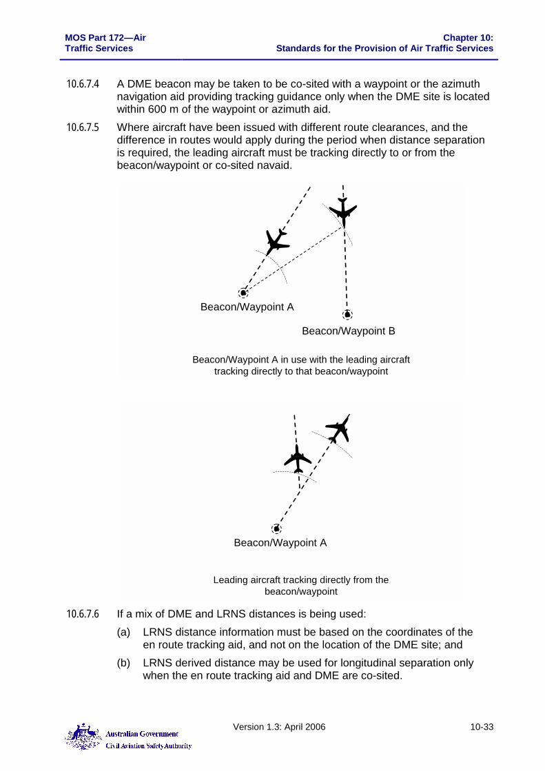
10.6.7.4 A DME beacon may be taken to be co-sited with a waypoint or the azimuth navigation aid providing tracking guidance only when the DME site is located within 600 m of the waypoint or azimuth aid.
10.6.7.5 Where aircraft have been issued with different route clearances, and the difference in routes would apply during the period when distance separation is required, the leading aircraft must be tracking directly to or from the beacon/waypoint or co-sited navaid.
Beacon/Waypoint B
Beacon/Waypoint A
Beacon/Waypoint A in use with the leading aircraft tracking directly to that beacon/waypoint
Leading aircraft tracking directly from the beacon/waypoint
Beacon/Waypoint A
10.6.7.6 If a mix of DME and LRNS distances is being used:
(a) LRNS distance information must be based on the coordinates of the en route tracking aid, and not on the location of the DME site; and
(b) LRNS derived distance may be used for longitudinal separation only when the en route tracking aid and DME are co-sited.

Chapter 10: Standards for the Provision of Air Traffic Services
MOS Part 172—Air Traffic Services
10-34 Version 1.3: April 2006
10.6.7.7 Where distance information is required from a specific navigation source, the source must be included in the request (e.g. “REPORT DISTANCE FROM NWN DME”, “REPORT GPS DISTANCE FROM BEZZA” or “REPORT RNAV DISTANCE FROM PONAN”).
10.6.7.8 During the application of same direction distance minima, the distance between aircraft must be checked at sufficient intervals to ensure that the required separation is maintained. The frequency of these regular distance checks will depend on the performance and disposition of the aircraft, but must be made at intervals not exceeding 30 MIN.
10.6.7.9 When the ATS surveillance system derived distance between the aircraft is less than the sum of the distance required by the procedural separation minimum and the applicable ATS surveillance system separation minimum, a distance check must be made before the first aircraft leaves ATS surveillance system coverage.
10.6.7.10 Separation minima D4, D7 and R3 (change of level) may also be applied between 2 aircraft if: (a) the aircraft are confirmed to be on opposite sides of an en-route
navigation aid, and 1 aircraft’s distance is established by RNAV/DME to be not closer to that aid than the distance required by the separation minimum; or
(b) the distance determined by an ATS surveillance system, or by the position of 1 identified aircraft and an RNAV/DME report from the other, establishes that the distance between the aircraft is at least the distance required by the procedural separation minimum plus the applicable ATS surveillance system separation minimum; or
(c) 1 aircraft’s distance is established by RNAV/DME and the second aircraft’s position is established, by day, with reference to a visual fix, if: (i) the fix is a prominent topographical feature within 10 000 ft of the
aircraft; and (ii) the feature is displayed on maps available to ATC.
10.6.7.11 Except for standard R6, closing speed between aircraft may exist provided that: (a) separation is in excess of the minimum distance required; (b) distance checks are made at intervals not exceeding 15 MIN; and (c) when aircraft are cruising at levels not vertically separated, the closing
speed is not greater than 35 KT IAS or M 0.06.

MOS Part 172—Air Traffic Services
Chapter 10:Standards for the Provision of Air Traffic Services
Version 1.3: April 2006 10-35
10.6.8 Use of DME/GPS Separation 10.6.8.1 In the description and application of these separation minima, ‘DME’ includes
TACAN for distance measurement. TACAN distances may be used for the same purpose as DME provided that all tolerances and conditions shown for DME are applied.
10.6.8.2 In CTA only, GPS distance information may be provided by GPSRNAV or GPSOCEANIC aircraft for the application of minima D1-4, subject to the following conditions: (a) where a mix of GPS and DME distances is used, distance reports must
not be used if one aircraft is within 20 NM of the reference point; (b) when GPS is used by both aircraft, the standard may also be applied
with reference to published waypoints.
10.6.9 RNAV Separation 10.6.9.1 RNAV distance minima may be applied between aircraft with approved
LRNS, or between an aircraft with approved LRNS equipment and an aircraft with DME.
10.6.9.2 RNAV minima must not be applied after pilot advice of: (a) operation of LRNS equipment outside prescribed criteria, including
deterioration or failure; or (b) operation of an INS/IRS outside the time limits specified in the
operational approval: (i) CTA – 5 hours multiple sensor or 3 hours single sensor; or (ii) OCA – 12 hours multiple sensor, 5 hours single sensor or 4.5
hours MNPS; or (c) continuous operation of GPSRNAV equipment in the DR mode for at
least 1 minute or non-RAIM operation for at least 10 min. 10.6.9.3 If there is concern that the update criteria mentioned in paragraphs 10.6.9.2
(a) and (b) may not be met throughout the application of an RNAV standard, the time of the last update must be obtained from the pilot.
10.6.9.4 All aircraft indicating either RNP10 or RNP4 approval in the flight notification [R in field 10a] are eligible for the application of AUSEP related separation standards providing other relevant conditions are met.
10.6.9.5 Separation based on RNP approval may only apply in RNP airspace. 10.6.9.6 The application of Lateral Separation using the Expanding Formulae for
RNP10 or RNP4 approved aircraft requires carriage of INS/IRS.

Chapter 10: Standards for the Provision of Air Traffic Services
MOS Part 172—Air Traffic Services
10-36 Version 1.3: April 2006
10.6.10 Longitudinal Distance Separation Using ADS-C 10.6.10.1 When using ADS-C reports from FANS-1/A aircraft as the sole means of
establishing and monitoring longitudinal distance separation standards, only those standards specifically identified as being approved for ADS-C may be used.
10.6.10.2 Methods of determining longitudinal distance separation using ADS-C may include: (a) the use of system tools to measure the distance between the displayed
positions of 2 or more FANS-1/A aircraft reporting by ADS-C; or (b) when both aircraft are within CTA — a comparison of the actual ADS-C
report symbol of a FANS-1/A aircraft with the position of another aircraft determined by an alternative form of position fixing, such as radar, ADS-B, voice or CPDLC reports.
10.6.10.3 All system tool tolerances must be taken into account in any measurement. 10.6.10.4 When 2 FANS-1/A aircraft reporting by ADS-C are flying on the same
identical tracks (same or opposite direction), the measurements may be taken directly between the 2 ADS-C symbols.
10.6.10.5 For a bend in track, the measurements may only be taken between each symbol and the turning point, not between the 2 symbols:

MOS Part 172—Air Traffic Services
Chapter 10:Standards for the Provision of Air Traffic Services
Version 1.3: April 2006 10-37
10.6.10.6 If 2 FANS-1/A aircraft are flying on diverging or converging route clearances, then measurements may be either to or from a common point on the route clearances:
or taken from where the abeam position of 1 aircraft intersects the route of the other.
10.6.10.7 When longitudinal distance separation is to be determined between FANS-1/A and non-FANS-1/A aircraft: (a) the measurement may only be commenced after receiving an ADS-C
report from the FANS-1/A aircraft; and (b) the request for the voice report must be made as soon as possible after
the ADS-C report symbol is displayed; and (c) this procedure may only be used when a distance greater than the
minimum of the applicable standard is available. 10.6.10.8 When comparing an ADS-C report symbol from a FANS-1/A aircraft with a
voice report from another aircraft, the measurement from or to the ADS-C symbol must be taken with reference to the beacon or waypoint reported by the other aircraft.

Chapter 10: Standards for the Provision of Air Traffic Services
MOS Part 172—Air Traffic Services
10-38 Version 1.3: April 2006
10.6.11 Distance Separation Minima
Minima Application Conditions Diagram
D1
20 NM
Climbing (for aircraft on climb to cruise)
1. Separation must be checked at sufficient intervals to ensure minimum separation is maintained.
2. Where B is climbing to a lower cruising level or both aircraft are climbing to levels that are not vertically separated, both A and B must report reaching their cruising levels.
3. If aircraft B reports at cruising level first, immediate action must be taken to apply an alternative standard.
4. Distance information must be derived from: (a) DME; or (b) in CTA only:
(i) GPSRNAV; or (ii) GPSOCEANIC.
A
B
DME
20 NM
D2
20 NM
Cruising (at levels not vertically separated)
1. Separation must be checked at sufficient intervals to ensure that minimum separation is maintained.
2. Distance information must be derived from: (a) DME; or (b) in CTA only:
(i) GPSRNAV; or (ii) GPSOCEANIC.
20 NMA B
MOS Part 172—Air Traffic Services Chapter 10: Standards for the Provision of Air Traffic Services
Version 1.3: April 2006 10-39
Minima Application Conditions Diagram
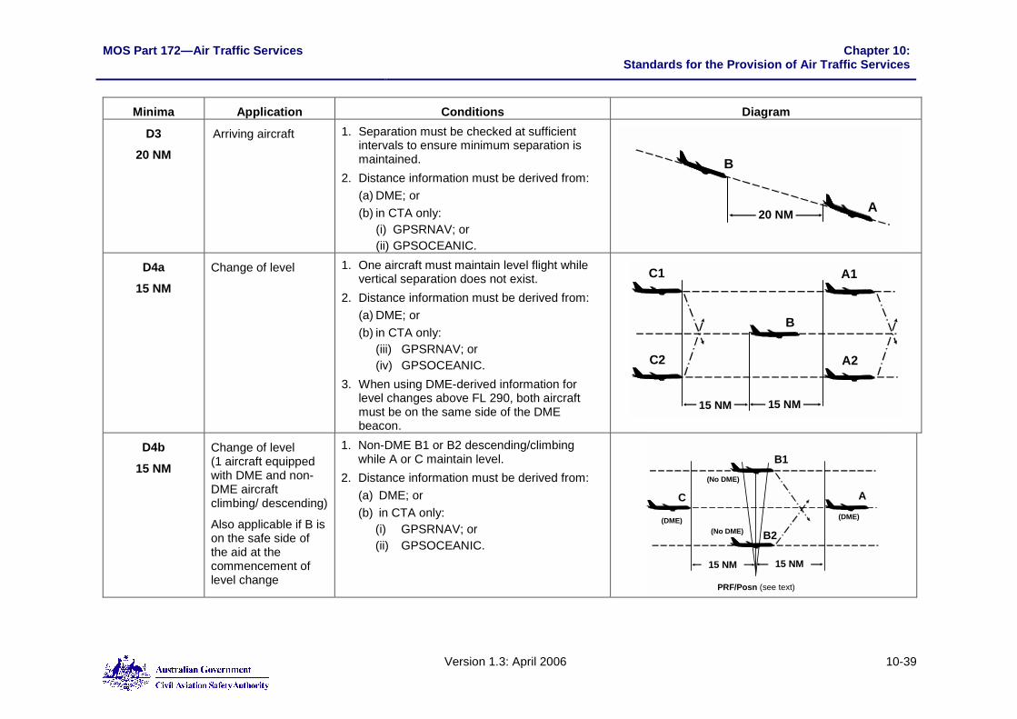
D3
20 NM
Arriving aircraft 1. Separation must be checked at sufficient intervals to ensure minimum separation is maintained.
2. Distance information must be derived from: (a) DME; or (b) in CTA only:
(i) GPSRNAV; or (ii) GPSOCEANIC.
A
B
20 NM
D4a
15 NM
Change of level 1. One aircraft must maintain level flight while vertical separation does not exist.
2. Distance information must be derived from: (a) DME; or (b) in CTA only:
(iii) GPSRNAV; or (iv) GPSOCEANIC.
3. When using DME-derived information for level changes above FL 290, both aircraft must be on the same side of the DME beacon.
B
A1
A2
15 NM15 NM
C1
C2
D4b
15 NM
Change of level (1 aircraft equipped with DME and non-DME aircraft climbing/ descending)
Also applicable if B is on the safe side of the aid at the commencement of level change
1. Non-DME B1 or B2 descending/climbing while A or C maintain level.
2. Distance information must be derived from: (a) DME; or (b) in CTA only:
(i) GPSRNAV; or (ii) GPSOCEANIC.
C A
15 NM
B1
B2
(DME)(DME)(No DME)
(No DME)
15 NM
PRF/Posn (see text)
Chapter 10: Standards for the Provision of Air Traffic Services
MOS Part 172—Air Traffic Services
10-40 Version 1.3: April 2006
Minima Application Conditions Diagram
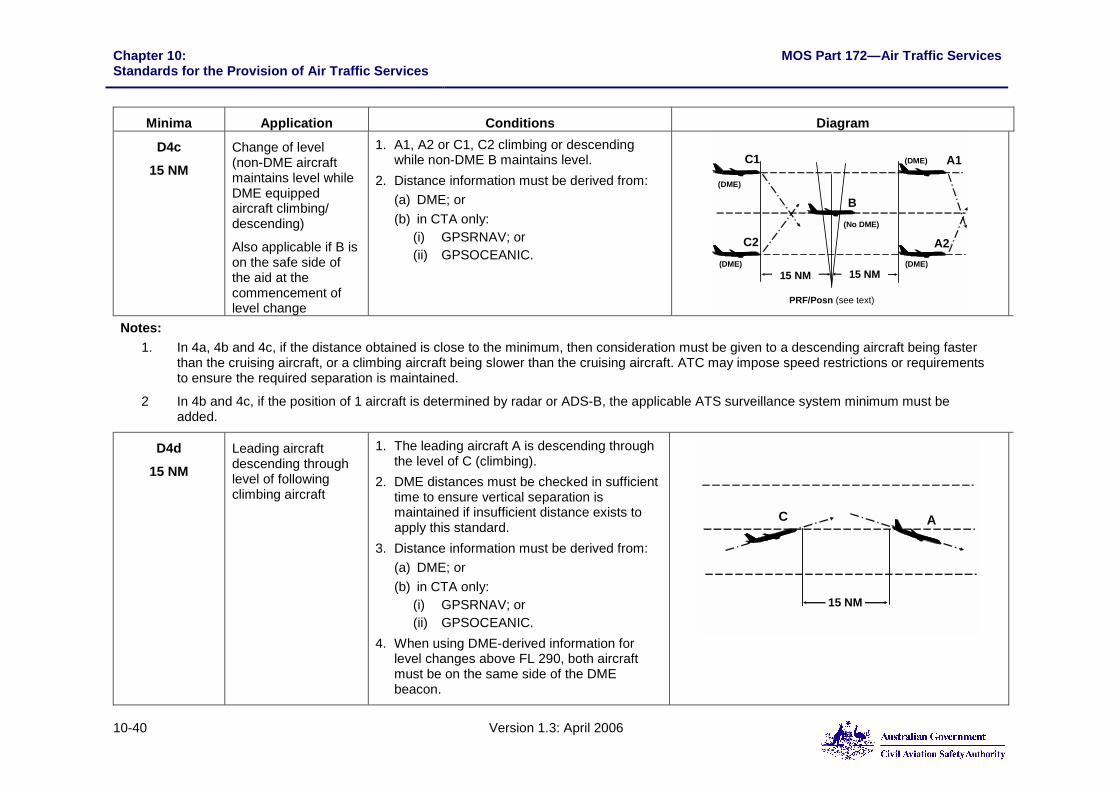
D4c
15 NM
Change of level (non-DME aircraft maintains level while DME equipped aircraft climbing/ descending)
Also applicable if B is on the safe side of the aid at the commencement of level change
1. A1, A2 or C1, C2 climbing or descending while non-DME B maintains level.
2. Distance information must be derived from: (a) DME; or (b) in CTA only:
(i) GPSRNAV; or (ii) GPSOCEANIC.
B
15 NM
C1
C2
(DME)
(No DME)
15 NM(DME)
A1
A2
(DME)
(DME)
PRF/Posn (see text) Notes:
1. In 4a, 4b and 4c, if the distance obtained is close to the minimum, then consideration must be given to a descending aircraft being faster than the cruising aircraft, or a climbing aircraft being slower than the cruising aircraft. ATC may impose speed restrictions or requirements to ensure the required separation is maintained.
2 In 4b and 4c, if the position of 1 aircraft is determined by radar or ADS-B, the applicable ATS surveillance system minimum must be added.
D4d
15 NM
Leading aircraft descending through level of following climbing aircraft
1. The leading aircraft A is descending through the level of C (climbing).
2. DME distances must be checked in sufficient time to ensure vertical separation is maintained if insufficient distance exists to apply this standard.
3. Distance information must be derived from: (a) DME; or (b) in CTA only:
(i) GPSRNAV; or (ii) GPSOCEANIC.
4. When using DME-derived information for level changes above FL 290, both aircraft must be on the same side of the DME beacon.
C
15 NM
A

MOS Part 172—Air Traffic Services Chapter 10: Standards for the Provision of Air Traffic Services
Version 1.3: April 2006 10-41
Minima Application Conditions Diagram
D4e
15 NM
Arriving Aircraft
Inbound aircraft to a controlled aerodrome
1. Both A and B are inbound aircraft and the leading aircraft A is within 30 NM of a controlled aerodrome with DME.
2. The aircraft are assigned levels that are vertically separated.
3. Distance information must be derived from: (a) DME; or (b) in CTA only:
(iii) GPSRNAV; or (iv) GPSOCEANIC. DME
AB
30 NM
15 NM
Controlled Aerodrome
D5
10 NM
Arriving Aircraft
Change of level 1. Both A and B are inbound aircraft and the leading aircraft A is within 20 NM of a controlled aerodrome with DME.
2. The aircraft are assigned levels which are vertically separated.
3. Both aircraft are DME equipped.
DME
AB
20 NM
10 NM
Controlled Aerodrome
D6
5 NM
Arriving Aircraft
Change of level 1. Both A and B are inbound aircraft and the leading aircraft A is within 15 NM of a controlled aerodrome with DME.
2. The aircraft are assigned levels which are vertically separated.
3. Both aircraft are DME equipped. 4. Wake turbulence standards are applied.
DME
AB
15 NM
5 NM
Controlled Aerodrome

Chapter 10: Standards for the Provision of Air Traffic Services
MOS Part 172—Air Traffic Services
10-42 Version 1.3: April 2006
Minima Application Conditions Diagram
D7
A DME distance
proportional to the rate of
closure (IAS) as determined
from the following DME
separation tables for
aircraft rate and amount of level change
Change of level
Also applicable if a non-DME equipped aircraft is on the safe side of the aid at the commencement of level change
1. One aircraft maintains level while vertical separation does not exist.
2. DME distances are checked when the aircraft are vertically separated by the minimum amount appropriate to the DME table to be used.
3. The level change is commenced within 1 min of obtaining DME distances. When the separation is on the minimum, instructions must be issued to ensure that the level change is commenced within this time.
4. Where the position of 1 aircraft is determined by an ATS surveillance system, the applicable ATS surveillance system minimum must be added.
5. When using DME-derived information for level changes above FL 290, both aircraft must be on the same side of the DME beacon.
6. When applying this separation minimum to an aircraft transiting the transition level and the Area QNH is higher than 1013 hPa, 1 000 ft must be added to the amount of level change and the applicable value in the table must then be utilised (e.g. for a 3 000 ft level change, use 4 000 ft table).
B
DME distance
from table
C1
C2
A1
A2
DME distance
from table
A
B1DME
distance from table
No DME faster
aircraft B2
PRF/Posn (see text)
B1DME
distance from table
ANo DME
Faster aircraft
B2
PRF/Posn (see text)

MOS Part 172—Air Traffic Services Chapter 10: Standards for the Provision of Air Traffic Services
Version 1.3: April 2006 10-43
Minima Application Conditions Diagram
DME150 190
40 50
40
40
50
50 60 7060
150 190
40
4040 50DME
Closing IAS (KT)
Closing IAS (KT)
500 FPM
1000 FPM
20003000
4000
20003000
4000
151515
0
1515
15
2020
20
2020
20
3030
30
50
30
3030
DME
DME
500 FPM
1000 FPM
50
100
1000
D8a
Definite Passing
10 NM
(12 NM at distances
greater than 180 NM)
Reciprocal tracks and tracks differing by more than 90 degrees
Reports indicate that the aircraft have passed and DME distance is opening.
A
B
10 or 12 NM as applicable
DMEA
B
C
D
10 or 12 NM as applicable
10 or 12 NM as applicable
More than 90°

Chapter 10: Standards for the Provision of Air Traffic Services
MOS Part 172—Air Traffic Services
10-44 Version 1.3: April 2006
Minima Application Conditions Diagram
D8b
Definite Passing
5 NM
Reciprocal tracks 1. Reports indicate that the aircraft have passed and DME distance is opening.
2. One aircraft is within 20 NM of the DME beacon.
5 NM
DME
A
B
20 NM
D8c
Definite Passing
10 NM
Reciprocal tracks 1. Reports by reference to a prominent topographical feature by 1 aircraft and a DME beacon by the other aircraft indicate that the aircraft have passed by at least 10 NM.
2. The non-DME equipped aircraft passes over and within 10 000 ft of the topographical feature.
3. The topographical feature together with its distance from the DME beacon is specified in local Instructions.
Town, Lake etc
A
B
10 NM

MOS Part 172—Air Traffic Services Chapter 10: Standards for the Provision of Air Traffic Services
Version 1.3: April 2006 10-45
10.6.12 RNAV Distance Separation Minima
Minima Application Conditions Diagram
R1
20 RNAV
Departing aircraft on climb to vertically separated cruising levels
1. Where B is climbing to the lower level, both A and B must report reaching their cruising levels.
2. If B reports at the cruising level first, immediate action must be taken to apply an alternative standard.
3. May only be used in CTA. 4. Aircraft must be approved:
(a) AUSEP; or (b) GPSRNAV; or (c) GPSOCEANIC; or (d) RNP10; or (e) RNP4.
A
B20 RNAV
R2
20 RNAV
Definite Passing 1. Using the same waypoint, reports indicate that the aircraft have passed and the distance between them must be opening.
2. Whenever a DME derived distance is 30 NM or less, a correction for DME Slant Range Error must be applied.
3. May only be used in CTA. 4. Aircraft must be approved:
(a) AUSEP; or (b) GPSRNAV; or (c) GPSOCEANIC; or (d) RNP10; or (e) RNP4.
20 RNAV

Chapter 10: Standards for the Provision of Air Traffic Services
MOS Part 172—Air Traffic Services
10-46 Version 1.3: April 2006
Minima Application Conditions Diagram
R3
30 RNAV
Climbing, cruising or descending
1. When both aircraft are climbing to non-vertically separated levels: (a) both A and B must report reaching their
cruising levels; and (b) if B reports at the cruising level first,
immediate action must be taken to ensure separation is maintained.
2. May only be used in CTA. 3. Aircraft must be approved:
(a) AUSEP; or (b) GPSRNAV; or (c) GPSOCEANIC; or (d) RNP10; or (e) RNP4.
4. When using DME-derived information for level changes above FL 290, both aircraft must be on the same side of the DME beacon.
A
B30 RNAV
A
30 RNAV
A
B
30 RNAV

MOS Part 172—Air Traffic Services Chapter 10: Standards for the Provision of Air Traffic Services
Version 1.3: April 2006 10-47
Minima Application Conditions Diagram
R4
50 RNAV
Aircraft cruising, climbing or descending on same track
1. Separation must be established by reference to the same ‘on-track’ waypoint, whenever possible ahead of both aircraft or by use of ADS-C.
2. Distance reports obtained by CPDLC must be sent by both aircraft at the same time or from the leading aircraft first.
3. When aircraft are at, or expected to reduce to, the minimum, speed control techniques, including assigning Mach number, must be applied to ensure that the minimum distance exists throughout the period of application of the standard.
4. If an aircraft fails to report its position within 3 min, immediate action must be taken to establish communication. If communication is not established within 8 min from the time the report should have been received, an alternative form of separation must be applied.
5. Both aircraft must be approved either RNP10 or RNP4.
6. Subject to subsection 10.6.7.11, distance reports must be obtained at least every 24 min.
A
50 RNAV
R5
50 RNAV
Definite Passing 1. Reports (including ADS-C reports) must indicate that the aircraft have passed and the distance between them is opening.
2. Both aircraft must be approved either RNP10 or RNP4.
50 RNAV

Chapter 10: Standards for the Provision of Air Traffic Services
MOS Part 172—Air Traffic Services
10-48 Version 1.3: April 2006
Minima Application Conditions Diagram
R6
80 RNAV
Mach No. Technique
Aircraft cruising, arriving and changing levels when not vertically separated
1. No closing Mach number may exist. 2. The Mach Number Technique (MNT) must be
applied during the application of the standard.
3. Aircraft must be approved: (a) AUSEP; or (b) GPSOCEANIC; or (c) MNPS.
Note: The requirement for ‘no closing’ may not be waived.
A
80 RNAV
R7
80 RNAV
Definite Passing
1. Using the same waypoint, reports must indicate that the aircraft have passed and the distance between them is opening.
2. Aircraft must be approved: (a) AUSEP; or (b) GPSOCEANIC; or (c) MNPS.
8 0 R N A V

MOS Part 172—Air Traffic Services Chapter 10: Standards for the Provision of Air Traffic Services
Version 1.3: April 2006 10-49
10.6.13 Distance Separation Minima using RNAV with Automatic Dependent Surveillance – Contact
Minima Application Conditions Diagram
A1
50 RNAV using ADS-C
Aircraft cruising, climbing or descending on same track
1. Separation must be established in accordance with subsection 10.6.10.
2. When aircraft are at, or expected to reduce to, the minimum, speed control techniques, including assigning Mach number, must be applied to ensure that the minimum distance exists throughout the period of application of the standard.
3. If an ADS-C periodic report is not received within 3 min of the time it should have been sent, action must be taken to establish communication. If communication is not established, or a periodic report is not received within 8 min from the time the periodic report should have been received, an alternative form of separation must be applied.
4. Both aircraft must be approved either RNP 10 or RNP 4.
5. Subject to subsection 10.6.7.11, distance or periodic ADS-C reports must be obtained at least every 24 min.
A
50 RNAV
A2
50 RNAV using ADS-C
Definite passing 1. ADS-C reports must indicate that the aircraft have passed and the distance between them is opening.
2. Both aircraft must be approved either RNP 10 or RNP 4.
3. Before the application of this standard, a Demand Contract Request (One shot) must be transmitted to each aircraft concerned.
50 RNAV

Chapter 10: Standards for the Provision of Air Traffic Services
MOS Part 172—Air Traffic Services
10-50 Version 1.3: April 2006
Intentionally Blank

MOS Part 172—Air Traffic Services Chapter 10:Standards for the Provision of Air Traffic Services
Version 1.3: April 2006 10-51
Section 10.7: Separation Standards—Vertical
10.7.1 Vertical Buffers between Aircraft Inside and Outside Controlled Airspace
10.7.1.1 Levels assigned to VFR aircraft must provide a buffer of at least 500 FT with the base of CTA.
10.7.1.2 If the base of CTA is a VFR level, levels assigned to IFR aircraft must provide a buffer of at least 500 ft with the base of CTA. If it is known that an IFR aircraft is operating less than 500 ft below the CTA base, levels assigned must provide a buffer of at least 1 000 ft with the base of CTA.
10.7.1.3 Where the base of CTA is an IFR level, levels assigned to IFR aircraft must provide a buffer of at least 1,000 FT with the base of CTA, unless it is known that no IFR traffic is operating at the base of CTA. In this instance a buffer of at least 500 FT must be applied.
10.7.2 Vertical Separation Below High Altitude Balloons 10.7.2.1 Unless visual separation is applied, aircraft in CTR/CTA must not be
permitted to transit vertically below the 15 NM radius of the balloons position while the balloon is ascending until the balloon has passed FL600.
10.7.3 Step Climbs and Descents 10.7.3.1 The Step Climb Procedure may be used to simultaneously climb aircraft to
vertically separated levels provided that the lower aircraft is progressively assigned levels that provide vertical separation with the higher aircraft.
10.7.3.2 When applying the step climb or step descent procedures, pilots must be advised that they are subject to a step climb or descent.
10.7.4 Specifying Rates of Climb 10.7.4.1 Except for international aircraft, a rate of climb or descent must be described
in each level clearance when a specified rate is required to ensure the vertical separation is maintained.
10.7.4.2 When it is necessary to specify a rate of climb or descent to an international aircraft, the rate must always be specified in feet per minute, not ‘standard rate’.
10.7.4.3 ATC must endeavour to avoid prescribing rate of climb or descent if it is believed that an aircraft is: (a) operating in close vertical proximity to the control area lower limit; or (b) descending VISUAL or VFR to an assigned level and maintaining
clearance from terrain or cloud. 10.7.4.4 A rate of descent must not be specified to any aircraft instructed to make a
‘VISUAL APPROACH” or “DME ARRIVAL”, or to an aircraft on that part of an instrument approach below the lowest holding altitude.

Chapter 10: Standards for the Provision of Air Traffic Services
MOS Part 172—Air Traffic Services
10-52 Version 1.3: April 2006
10.7.5 Rate in Step Climb/Descent 10.7.5.1 During a Step Climb or Step Descent where a rate of climb or descent has
been specified, the rate must apply to all level clearances issued in the course of the climb or descent. The rate must be specified in the initial clearance using the phrase: “... STEP CLIMB (or STEP DESCENT) - STANDARD RATE (or at FEET PER MINUTE)”.
10.7.6 Assigning Vacated Levels 10.7.6.1 A level vacated by one aircraft may be assigned immediately to a second
aircraft provided that: (a) the required vertical separation has not been increased because of the
possibility of turbulence; (b) the first aircraft has been assigned a level requiring a level change of at
least the minimum being applied; and (c) both aircraft have been instructed to change level at a specified rate
which will ensure that the applicable vertical separation standard is not infringed.
10.7.6.2 The lowest holding altitude may be assigned to a second aircraft when the first aircraft has reported, “ON FINAL - LEFT (final approach altitude)”, provided that the following aircraft is instructed to descend at “STANDARD RATE” (or at 500 FT per minute).
10.7.7 Vertical Separation Using ADS-C 10.7.7.1 A tolerance of ± 200 ft must be applied to ADS-C level information. 10.7.7.2 ADS-C level information may be used for the application of vertical
separation if: (a) the reported ADS-C level is FL 130 or above; and (b) displayed ADS-C level information is within the specified tolerance of
the expected or cleared flight level. 10.7.7.3 An aircraft cleared to leave a level is taken to have commenced its
manoeuvre and vacated the previously occupied level when the ADS-C-derived level information indicates a change of 400 ft or more in the anticipated direction from its previously assigned level.
10.7.7.4 If displayed ADS-C level information for an aircraft maintaining a level does not conform to the required tolerance, the controller must send a demand contract request to update the level displayed.
10.7.7.5 If, following the update, the level is still beyond the required tolerances, the pilot must be advised accordingly and requested to confirm the aircraft’s level. If, following confirmation of the level, the displayed ADS-C level information is still beyond the required tolerance, another method of separation or another method of determining level information must be applied.

MOS Part 172—Air Traffic Services Chapter 10:Standards for the Provision of Air Traffic Services
Version 1.3: April 2006 10-53
10.7.8 Transition Layer, Altitude and Level 10.7.8.1 The system of altimetry used in Australia makes use of a Transition Layer
between the Transition Altitude of 10,000 FT and the Transition Level of FL110, to separate aircraft using QNH from those using 1013 Hpa. Cruising in the transition layer must not be permitted.
10.7.9 Common Altimeter Settings 10.7.9.1 In the application of vertical separation at or below the transition altitude,
aircraft using terminal QNH and aircraft using Area QNH may be considered to be using common settings.
10.7.10 Levels Unavailable when QNH less than 1013 10.7.10.1 Whenever the QNH/Area QNH is less than 1013 HPa, certain flight levels at
or above the transition level are precluded from use in accordance with Table 10.7-1 (below): Table 10.7-1
QNH less than Level not available
1013 HPa FL110
997 HPa FL115
980 HPa FL120

Chapter 10: Standards for the Provision of Air Traffic Services
MOS Part 172—Air Traffic Services
10-54 Version 1.3: April 2006
10.7.11 Vertical Separation Minima Minima Application Conditions Diagram
V1
500 ft
1. Between IFR and VFR flights; or 2. Between SVFR flights, where
SVFR clearance is due to visibility
1. Both aircraft are 7 000 kg MTOW or less.
2. Both aircraft are at or below 10 000 ft. 3. Traffic information is provided to the
IFR flight, unless it is impracticable.
500 ft
All aircraft Up to and including FL 290. V2
1 000 ft Aircraft with RVSM approval, except military formation flights operating in airspace in which a Class A service is being provided
From FL 290 to FL 410 inclusive. 1 000 ft
1. Between aircraft, when at least 1
is not RVSM approved, or 2. Following pilot report of an
inability to comply with RVSM, or 3. Military formation flights
regardless of the individual RVSM approval state of each aircraft within the formation
1. From FL 290 to FL 410 inclusive.
All aircraft Above FL 410.
V3
2 000 ft
In known standing wave conditions or severe turbulence
All levels.
2 000 ft
V4
3 000 ft When 1 or more aircraft is operating at supersonic speeds
All levels.
3 000 ft

MOS Part 172—Air Traffic Services Chapter 10:Standards for the Provision of Air Traffic Services
Version 1.3: April 2006 10-55
Section 10.8: Separation Standards—Lateral
10.8.1 Lateral Separation Buffer 10.8.1.1 The Lateral Separation buffer is 1 NM between the possible positions of two
aircraft. (ICAO PANS-ATM, Chapter 5.)
10.8.2 Application of Lateral Separation 10.8.2.1 Lateral separation may be achieved by:
(a) establishing an aircraft’s position outside the BLSP; or (b) applying an appropriate ATS surveillance system minimum; or (c) applying a 1 NM buffer to the track or position of an aircraft which is
determined relative to a prominent topographical feature, if: (i) the aircraft is tracking visually; and (ii) the aircraft is not more than 10 000 ft above the topographical
feature; and (iii) it is daytime.
10.8.2.2 Entry and Exit Points must be established by: (a) application to a BLSP of slant range and DME equipment error
corrections; (b) application of RNAV tolerances; (c) passage over a visual fix located on the opposite side of a BLSP from
the area of conflict; (d) passage over a positive radio fix () located on the opposite side of a
BLSP from the area of conflict; (e) expiration of a time calculated using an estimate for a BLSP plus or
minus: (i) 5 minutes, if the estimate for the BLSP is within 30 min of an ATD,
passage over a visual fix, PRF, way point or ATS surveillance system position; or
(ii) half of the longitudinal time separation minimum applicable to the aircraft.
10.8.2.3 Aircraft transiting into an airspace in which larger tolerances are applied than that being exited are taken to be separated if: (a) the smaller separation standard exists; and (b) the aircraft are established on flight paths that will diverge by at least
15° until the larger separation standard is established; and (c) the aircraft are RNAV approved to AUSEP, MNPS, GPSOCEANIC
RNP10 or RNP4.

Chapter 10: Standards for the Provision of Air Traffic Services
MOS Part 172—Air Traffic Services
10-56 Version 1.3: April 2006
10.8.2.4 A DME-based lateral separation entry/exit point must be calculated by: (a) determining the ground distance from the DME site to the BLSP; then (b) if the area of conflict (or part of it) is between the BLSP and the DME
site, adding the slant range correction from Table 10.8-1 to the ground distance; then
(c) applying the correction for DME equipment error from Table 10.8-2 ensuring it is applied to a position outside the area of conflict.
10.8.2.5 Where the navigation tolerance is determined with reference to ground-based navigation aids, GPS distance may be used in lieu of a co-sited DME in the steps above.
10.8.2.6 Where the lateral separation point is less than 60 NM from, and between the area of conflict and the reference DME site, an extra 1NM must be subtracted from the DME-derived distance.
10.8.3 Navigation Tolerances 10.8.3.1 To determine the possible position of an aircraft, the following tolerance
areas and range limitations must be applied. 10.8.3.2 When manual means are used for the calculation of lateral separation, the
radio navaid tolerances specified below must be rounded up to the next higher half-degree.
10.8.3.3 The minimum tracking tolerance is ±1 NM. 10.8.3.4 The maximum tracking tolerance is ±30 NM in CTA and ± 50 NM in OCA. 10.8.3.5 Slant range corrections are as follows.
Table 10.8-1
Slant Range Correction (in NM) Ground Distance < = FL150 < = FL290 < = FL460 < = FL600
3 NM 2 3 6 8 4–5 NM 1 3 5 7 6–7 NM 1 2 4 6
8 NM 1 2 4 5 9–10 NM 1 2 3 5 11–12 NM 1 2 3 4 13–14 NM 1 1 3 4
15 NM 1 1 2 4 16–24 NM 1 1 2 3 25–30 NM 1 1 2 2 31–50 NM 1 1 1 2 >50 NM 1 1 1 1

MOS Part 172—Air Traffic Services Chapter 10:Standards for the Provision of Air Traffic Services
Version 1.3: April 2006 10-57
10.8.3.6 Slant Range Error is negligible and corrections need not be applied at or below: (a) 2,000 FT AGL at distances of 10 NM or greater from the DME site; or (b) 4,000 FT AGL at distances of 30 NM or greater from the DME site.
Note: Where required for a particular lateral separation problem, Local Instructions may specify a lateral separation point based on a precise slant range correction for the levels concerned.
10.8.3.7 DME equipment error corrections are as follows: Table 10.8-2
DME Equipment Error
Tolerance Conditions
Controllers may use figures from the table below.
DME Equipment Error Correction
± 0.25 NM plus 1.25% of the slant range.
Slant Range
300 NM or less
220 NM or less
140 NM or less
60 NM or less
Correction
4 NM
3 NM
2 NM
1 NM

Chapter 10: Standards for the Provision of Air Traffic Services
MOS Part 172—Air Traffic Services
10-58 Version 1.3: April 2006
10.8.3.8 The following tolerances are applicable to short range navigation aids: Table 10.8-3
Navigation Aid
Tolerance for Precise
Plotting
Tolerance for Manual Plotting
Conditions
ILS Localiser Front Beam
± 2.4 ° ± 2.5° Within 25 NM except: 1. Above 2,000 FT AGL, within ±5° of course
line 25 NM; 2. Below A050 30 NM; 3. A050 and above 50 NM.
VOR radials (or TACAN)
± 5.2° ± 5.5° Range (based on height above the navaid): Below 5,000 FT 60 NM 5,000 to 9,999 FT 90 NM 10,000 to 14,999 FT 120 NM 15,000 to 19,999 FT 150 NM At or above 20,000 FT 180 NM*
Note: For published lateral separation diagrams that are displayed for controller reference, a maximum range of 150 NM must be used.
The tolerance can be applied outside the listed range when an inbound aircraft has reported established on the VOR/TACAN.
NDB/Locator ± 6.9° ± 7° Range as per ERSA.
DME arc ± 2.5 NM ± 2.5 NM Includes DME equipment error.
10.8.3.9 The following Circular Error of Position (CEP) tolerances are applicable to long range navigation systems: Table 10.8-4
Navigation Aid Tolerance Conditions
Approved LRNS – complies with specified RNP.
25 NM – CEP Where both aircraft meet RNP10 capability, and in OCA, where RNP10 is specified.
Note: 1 NM buffer between tolerances not required (refer ‘Lateral Separation Table’).
Approved LRNS – General method.
14 NM – CEP CTA – when manual plotting or calculation is required. Approved LRNS for application of this tolerance are those indicating: • AUSEP • GPSOCEANIC • GPSRNAV.

MOS Part 172—Air Traffic Services Chapter 10:Standards for the Provision of Air Traffic Services
Version 1.3: April 2006 10-59
Navigation Aid Tolerance Conditions
Approved GPS 12 NM – CEP CTA – for use on fixed/published routes. Approved LRNS for application of this tolerance are those indicating: • GPSOCEANIC; • GPSRNAV.
Approved INS/IRS Expanding formula
In CTA. The following formula may only be used in the preparation of an approved Lateral Separation diagram. Applicable to AUSEP aircraft only.
The tolerance is a circle of radius: • 3 NM on departure; or • 4 NM at update; and • expanding at 3 NM per hour since
departure or update to a maximum of 14 NM.
ATC can assume update when the following conditions exist: • within 180 NM of both DME stations for a
DME/DME fix where the position lines cross at an angle between 30° and 150°;
• from a collocated VOR/DME beacon provided the aircraft is not more than 25 NM past that beacon;
• overhead a VOR beacon at or below FL200.
10.8.3.10 The following tolerances are applicable to visual tracking and position fixing: Table 10.8-5
Conditions Tolerance
By day—powered aircraft
0 to 2,000 FT AGL
2,001 to 5,000 FT AGL
5,001 to 10,000 FT AGL
±1 NM
±2 NM
±4 NM
By day—non-powered glider aircraft
0 to 10,000 FT AGL ±5 NM
By night 0 to 2,000 FT AGL
2,001 to 5,000 FT AGL
5,001 to 10,000 FT AGL
±2 NM
±3 NM
±5 NM
By day and night 10,001 FT AGL to FL200
FL201 to FL300
FL301 to FL400
±8 NM
±12 NM
±16 NM

Chapter 10: Standards for the Provision of Air Traffic Services
MOS Part 172—Air Traffic Services
10-60 Version 1.3: April 2006
10.8.3.11 The following miscellaneous tolerances are applicable: Table 10.8-6
Means of Position Fixing
Tolerance Conditions
Navigation Training 20 NM CEP Flight Notification specifies SAN/NAVEX or FTS/NAVEX.
Allows for along track and cross-track errors.
Dead Reckoning ± 12°
± 9° Initial track guidance has been provided by NDB, VOR, or TACAN and there is no subsequent change in track.
Flight path monitoring
± 9° 1. Aircraft is observed on the ATS surveillance system to maintain track.
2. Tolerance applied from the edge of a circle of 5 NM centred on the last observed position.
3. When using radar, the distance from the radar site is less than 200 NM.

MOS Part 172—Air Traffic Services Chapter 10:Standards for the Provision of Air Traffic Services
Version 1.3: April 2006 10-61
Section 10.9: Separation Standards—Applicable to En-route Area Navigation by Aircraft Using Inertial Navigation
Systems
10.9.1 Introduction 10.9.1.1 This section is concerned with the horizontal (that is, lateral and longitudinal)
separation standards to be employed by ATC in respect of aircraft equipped for en-route area navigation (RNAV) and approved for such operations.
10.9.1.2 The standards must not be applied when ATC is aware that the time since the last opportunity to update the RNAV system’s present position exceeds the limit, or after pilot advice of: (a) navigation equipment failure; or (b) operation of the equipment outside the approved tolerances.
10.9.2 Lateral Separation 10.9.2.1 The following tolerances across track may be applied to RNAV derived
position for lateral separation: (a) ±15 NM in CTA/TCTA and in OCA provided that the update interval
(that is, the flight time since departure or a waypoint suitable for updating present position) does not exceed 3 hours for aircraft equipped with single RNAV equipment or 5 hours for aircraft with 2 or more RNAV equipments; or
(b) ±30 NM in OCA. 10.9.2.2 For lateral separation the across-track tolerance to be applied is to equal the
CEP of the INS/IRS-derived position plus the FTE. 10.9.2.3 The CEP is determined from the following:
(a) at departure point the INS/IRS position can be assumed to be within a circle of radius 3 NM;
(b) the INS/IRS position can be assumed to be within a circle of radius 4 NM at a designated waypoint suitable for updating inertial present position;
(c) the CEP of the INS/IRS position expands at a rate corresponding to an increase in radius of 3 NM per hour (e.g. for a groundspeed of 300KT, divergence is 1 NM per 100 NM track flown).
10.9.2.4 The FTE when the autopilot is not coupled to the INS/IRS for steering guidance is ±2 NM across track.
10.9.2.5 Within the coverage of a short-range radio navigation aid (e.g. VOR, NDB, DME) defining the route, the tolerance applicable to that aid is to be used if it is less than that of the RNAV system.

Chapter 10: Standards for the Provision of Air Traffic Services
MOS Part 172—Air Traffic Services
10-62 Version 1.3: April 2006
10.9.3 Longitudinal Separation 10.9.3.1 The longitudinal separation minima based on time are derived by taking the
following factors into account: (a) the along-track navigational tolerances, assumed to be:
(i) the same for each aircraft; (ii) equal to the magnitude of the radial error of position of the least
accurate navigation system; and (iii) calculated at the end of a route section, the end being defined as
either: (A) A waypoint satisfying the parameters for updating present
position; or (B) A ‘gate-in’ waypoint marked by NDB, VOR, DME or a
combination thereof, for entry into the radio-navigation air route structure; or
(C) A waypoint beyond which a larger separation standard is specified;
(b) the tolerance of each aircraft’s estimated arrival time at the next reporting point (taken as ±3 MIN);
(c) an estimation tolerance of ±2 MIN to allow for errors in the ATC’s estimation of future positions of the aircraft in conflict;
(d) a control tolerance of ±2 MIN for control factors such as communications delays, clock errors and human factors;
(e) each of these tolerances is combined by the root sum square (RSS) method; and
(f) a buffer of 3 MIN added arithmetically. 10.9.3.2 The minimum time separation between two aircraft which are neither laterally
nor vertically separated, therefore, equals:
323/60..2 22
2
+
++
=
SGdTsep MIN,
Where: d = magnitude of the CEP (NM) and G/S = minimum groundspeed (KT).
10.9.3.3 10 MIN separation between aircraft flying the same or reciprocal tracks may apply within controlled airspace provided that: (a) for aircraft equipped with single INS/IRS the average groundspeed on a
route section is not less than: (i) 240 KT in CTA/TCTA/OCA and the update interval does not
exceed 3 hours; or (ii) 330 KT in OCA and the update interval does not exceed 5 hours; and

MOS Part 172—Air Traffic Services Chapter 10:Standards for the Provision of Air Traffic Services
Version 1.3: April 2006 10-63
(b) for aircraft equipped with two or more INS/IRS, the average groundspeed on a route section is not less than 240 KT and the update interval does not exceed 5 hours.
10.9.3.4 15 MIN separation between aircraft flying the same or reciprocal tracks may apply within controlled airspace provided that: (a) for aircraft equipped with single INS/IRS, the update interval does not
exceed 5 hours; and (b) for aircraft equipped with two or more INS/IRS, the average
groundspeed on a route section is not less than 240 KT and the update interval does not exceed 12 hours.
10.9.3.5 20 MIN separation between aircraft flying the same or reciprocal tracks may apply within controlled airspace provided that: (a) for aircraft equipped with single INS/IRS, the update interval does not
exceed 5 hours; and (b) for aircraft equipped with two or more INS/IRS, the update interval does
not exceed 12 hours.
10.9.4 Distance Standards 10.9.4.1 The longitudinal separation minima based on distance are derived using the
following assumptions and methods: (a) the along-track navigational tolerance of an aircraft is taken as the
same as for the time standards; (b) when “NO CLOSING SPEED” is stipulated as a condition, minor
variations of 4% of TAS of each aircraft, taken as 450 KT for the initial climb and 600 KT maximum thereafter, are allowed;
(c) when separation is to be checked at “FREQUENT INTERVALS” to ensure that the minimum will not be infringed, the maximum interval between checks is taken as 15 MIN;
(d) each of these tolerances is combined by the RSS method; (e) except in the case of the R2 (definite passing) standard, a buffer of 10 NM
is added arithmetically. The distance standard, therefore, equals:
( ) nm.2 22bc ddd +
+
where: d = magnitude of the CEP (NM) dc = ‘closure’ distance of each aircraft owing to TAS variation = 3 NM for initial climb = 6 NM for cruise, arrival and change of level db = buffer =10 NM (except in case of R2) = 0 (R2 only).

Chapter 10: Standards for the Provision of Air Traffic Services
MOS Part 172—Air Traffic Services
10-64 Version 1.3: April 2006
10.9.4.2 The method of application of distance separation minima, together with relevant minima are contained in paragraphs 10.6.7 to 10.6.13.
10.9.5 Explanation of Derivation of Longitudinal Separation Standards 10.9.5.1 Tolerances used in the deviation of longitudinal separation standards are:
(a) initial climb: (i) INS/IR ± 5 NM along track (ii) DME ± 5 NM.
(b) cruise, arrival, change of level and definite passing: (i) Single INS/IRS:
± 8.5 NM along track up to 1.5 hours ± 12.4 NM along track up to 3 hours ± 18.2 NM along track up to 5 hours
(ii) Dual INS/IRS: ± 12.9 NM along track up to 5 hours ± 27.7 NM along track up to 12 hours
(iii) DME: ± 6 NM. For flight times exceeding 1.5 hours, INS/IRS tolerances are the largest.
10.9.5.2 The minimum time separation (Tsep) between two aircraft is given by:
323/60..2 22
2
+
++
=
SGdTsep MIN,
where: d = magnitude of the CEP (NM) G/S = minimum groundspeed (KT) Alternatively, the equation can be expressed as:
( )knots
1
2133
60/2 −
−−=
TsepdSG
(a) 10 MIN separation (Tsep = 10 MIN): (i) For single INS/IRS with 3 hourly updating (d = 12.4 NM)
G/S = 219 KT. (ii) for single INS/IRS with 5 hourly updating (d = 18.2 NM)
G/S = 322 KT.

MOS Part 172—Air Traffic Services Chapter 10:Standards for the Provision of Air Traffic Services
Version 1.3: April 2006 10-65
(iii) for dual INS/IRS with 5 hourly updating (d = 12.9 NM) G/S = 228 KT.
(iv) or dual INS/IRS with 12 hourly updating (d = 27.7 NM) G/S = 490 KT.
(b) 15 minute separation (Tsep = 15 min): (i) for single INS/IRS with 3 hourly updating (d = 12.4 NM)
G/S = 97 KT. (ii) for single INS/IRS with 5 hourly updating (d = 18.2 NM)
G/S = 142 KT. (iii) for dual INS/IRS with 5 hourly updating (d = 12.9 NM)
G/S = 101 KT. (iv) for dual INS/IRS with 12 hourly updating (d = 27.7 NM)
G/S = 216 KT. (c) 20 minute separation (Tsep = 20 MIN):
(i) for single INS/IRS with 3 hourly updating (d = 12.4 NM) G/S = 65 KT.
(ii) for single INS/IRS with 5 hourly updating (d = 18.2 NM) G/S = 95 KT.
(iii) for dual INS/IRS with 5 hourly updating (d =12.9 NM) G/S = 67 KT.
(iv) for dual INS/IRS with 12 hourly updating (d = 27.7 NM) G/S = 145 KT.
(d) for simplicity, these minimum groundspeeds are rationalised as follows: (i) a minimum groundspeed of 150 KT is assumed unless otherwise
stated. (ii) the situation requiring a minimum groundspeed of 490 KT is
ignored. (iii) the remaining minimum groundspeeds are rounded-up to the next
multiple of 30 knot (that is, 240 and 330 KT).

Chapter 10: Standards for the Provision of Air Traffic Services
MOS Part 172—Air Traffic Services
10-66 Version 1.3: April 2006
10.9.5.3 The minimum distance separation (Rsep) between two aircraft is given by:
( ) nm.2 22bc dddRsep +
+=
where d = magnitude of the CEP (NM) dc = closure distance of each aircraft owing to TAS variation = 3 NM for initial climb = 6 NM for cruise, arrival and change of level db = buffer = 10 NM (except in case of R2) = 0 NM (R2 only)
(a) aircraft on climb to cruising level (R1):
( ) nm1035.2 22 ++=Rsep
=18 NM. Rounded up R1 = 20 NM.
(b) definite passing (R2 and R2A): (i) For dual INS/IRS with 5 hourly updating
( )nm69.12.2 22 +=Rsep
= 20 NM = R2. (ii) For dual INS/IRS with 12 hourly updating,
( )nm67.27.2 22 +=Rsep
= 40 NM = R2A. (c) aircraft cruising, arriving or changing level (R3 and R3A):
(i) R3 = R2 + 10 NM (buffer) = 30 NM 10.9.5.4 R3A = R2A + 10 NM = 50 NM.

MOS Part 172—Air Traffic Services Chapter 10:Standards for the Provision of Air Traffic Services
Version 1.3: April 2006 10-67
Section 10.10: Separation Standards—Visual
10.10.1 Application 10.10.1.1 Visual separation may be achieved:
(a) by the use of visual procedures; or (b) by assigning visual separation responsibility to a pilot.
10.10.1.2 When applying visual separation, controllers consideration must be given to aircraft performance characteristics, particularly in relation to faster following aircraft. When necessary, corroborative evidence from the pilot of one aircraft on the relative position of another aircraft must be obtained.
10.10.1.3 Responsibility for separation must only be assigned to a pilot as follows: (a) for arriving aircraft above FL125, by instructing the pilot of one aircraft
to follow on the same track, behind another aircraft, provided the pilot has reported sighting the other aircraft, and at least one of the aircraft is on descent; or
(b) when the aircraft to be separated are operating at or below FL125 and will continue to do so during the application of this standard, the pilot of one aircraft reports sighting the other aircraft and is instructed to maintain visual separation with or to follow that aircraft.
10.10.1.4 Before altering the clearance of an aircraft with which visual separation has been assigned to another aircraft, the controller must ensure that visual separation can continue to be maintained.
10.10.1.5 Alternative instructions must be issued to provide separation if there is any doubt of the pilot’s ability to keep the other aircraft in sight or maintain separation.
10.10.1.6 Positive identification must be established before visual separation is provided as follows: (a) by day:
(i) identification by type; (ii) identification by distinguishing markings if aircraft are of the same
type; (iii) identification by observing a change of heading or altitude of one
of the relevant aircraft. (b) by night:
(i) momentarily extinguish navigation lights; (ii) select flashing navigation lights to steady; (iii) extinguish hazard beacon; (iv) momentarily switch on landing lights; (v) change heading.

Chapter 10: Standards for the Provision of Air Traffic Services
MOS Part 172—Air Traffic Services
10-68 Version 1.3: April 2006
10.10.1.7 Visual Separation between an aircraft and a high altitude balloon may be applied provided that: (a) the confirmed drift of the balloon is away from the aircraft; (b) the balloon is ascending; and (c) the operations are being conducted during daylight.
10.10.1.8 Relevant traffic information must be passed in sufficient time and detail to enable the pilot to identify and maintain separation from the other aircraft.
10.10.1.9 In circumstances where an aircraft has been instructed to maintain separation from, but not follow, an IFR aircraft, traffic information must be issued to the IFR aircraft, including advice that responsibility for separation has been assigned to the other aircraft.
10.10.1.10 The traffic information provided must contain as much as is necessary of the following to assist the pilot in identifying the other aircraft: (a) type, and description if unfamiliar; (b) level; (c) position information either by clock reference, bearing and distance,
relation to a geographical point, reported position and estimate, or position in the circuit;
(d) intentions, or direction of flight.
10.10.2 Separation Using Visual Observation 10.10.2.1 When weather conditions permit, the aerodrome controller may provide
separation based on visual observations as coordinated with Approach Control provided that: (a) the aerodrome controller is in agreement and accepts responsibility for
the provision of such visual control; (b) where required, the aircraft concerned are on the aerodrome control
frequency; (c) where required, specific airspace is released to the aerodrome
controller for the purpose of providing such control. 10.10.2.2 Aerodrome controllers may also separate by the use of visual observation of
aircraft position and projected flight paths. 10.10.2.3 When aircraft are operating visually as aerodrome traffic ATC must issue 1 or
more of the following: (a) clearances designed to maintain separation; (b) sequencing instructions; (c) relevant traffic information.
10.10.2.4 Pilots must be advised of their number in the landing sequence to assist in identification of traffic.

MOS Part 172—Air Traffic Services Chapter 10:Standards for the Provision of Air Traffic Services
Version 1.3: April 2006 10-69
10.10.2.5 ATC must maintain, as far as possible, a continuous visual watch to detect and determine the position, and ensure the safety of, aircraft.
10.10.3 Separating Approaching Aircraft Beyond Tower View 10.10.3.1 Two approaching aircraft are deemed to be separated while the second
approaching aircraft is on final approach beyond the view of the tower controller if, before commencing such final approach, the first approaching aircraft: (a) has been sighted by the tower controller, there is reasonable assurance
that a landing can be accomplished, and it is clear that no confliction will occur; or
(b) has reported commencing a missed approach, and is proceeding from a point and on a clearance such that separation could readily be maintained should the second approaching aircraft miss its approach.
10.10.3.2 Unless cleared at or before passing 10 NM from the aerodrome, this form of separation is not acceptable and another must be provided.

Chapter 10: Standards for the Provision of Air Traffic Services
MOS Part 172—Air Traffic Services
10-70 Version 1.3: April 2006
Intentionally Blank .

MOS Part 172—Air Traffic Services Chapter 10:Standards for the Provision of Air Traffic Services
Version 1.3: April 2006 10-71
1NMPilot specified distance
1NMPilot specified distance
1NM
1NM
1NM
Section 10.11: Separation Standards—Miscellaneous
10.11.1 Parachute Jumping Exercise (PJE) 10.11.1.1 Separation between aircraft involved in PJE at the same drop zone is the
responsibility of the pilots of the PJE aircraft. Separation between PJE aircraft and the parachutist is the sole responsibility of the pilots of the PJE aircraft.
10.11.1.2 ATC must provide traffic information to PJE aircraft, and, except in Class E or G airspace, apply separation between parachutists and non-PJE aircraft.
10.11.1.3 ATC must make a broadcast on the appropriate frequency before the drop as an alert to pilots of flights operating in the airspace.
10.11.1.4 In Class E airspace, ATC must also provide traffic information to IFR non-PJE aircraft about PJE aircraft.
10.11.1.5 Where two or more PJE Drop Zones are located in close proximity and parachute operators have mutually agreed to accept self-separation, ATC is required to pass only traffic information to the participating operators. A participating pilot may request a separation service, but must continue to self-separate until ATC is satisfied that a separation standard has been achieved, and can be maintained. Agreements established between parachute operators to self-separate must be documented in ATS Local Instructions.
10.11.2 Limitations and Extensions – PJE 10.11.2.1 For separation purposes, ATC must base separation on the fact that the
parachutist will be dropped within a 1 NM radius of the target. If an extension of this area is necessary, the pilot must advise ATS of the distance and direction this extension is required. The navigational tolerance area must be extended in the advised direction until receipt of advice that the drop is completed. These requirements should be reiterated in any briefing.

Chapter 10: Standards for the Provision of Air Traffic Services
MOS Part 172—Air Traffic Services
10-72 Version 1.3: April 2006
10.11.2.2 Where parachutists agree to remain to one side of a defined line feature, and the target is set at least 200 M away from the closest point of the line feature, the navigational tolerance area of the parachutists may be reduced to the line feature. The line feature may only be used when the drop will occur from 10,000 FT or below, by day in VMC, and the service provider agrees to the use of the line feature. A letter of agreement between the parachute jumping group and ATS must be established.
Line feature
Target 200m from the line feature
Note: Parachutists will remain within 1 NM of the target on the same side of the line feature
10.11.2.3 The instructions described above should be issued by directly briefing the
parachutists prior to the exercise. They may also be relayed to the parachutists by the PJE aircraft pilot.
10.11.2.4 Parachutists may be assigned responsibility to remain within certain limits of, and on a particular side of a geographical fix (e.g. “PARACHUTISTS REMAIN WITHIN 1 NM OF THE TARGET AND TO THE WEST OF (line feature)”).
10.11.2.5 Responsibility for separation of parachutists from another aircraft must only be assigned to the PJE aircraft.
10.11.2.6 Lateral separation may be achieved between the parachutists and the non-PJE aircraft by a requirement stipulated to the parachutists in accordance with the use of a line feature for separation, and the application of visual tracking tolerances to the aircraft.
10.11.2.7 After the parachutists have exited, and the PJE aircraft has commenced descent, only the pilot of the PJE aircraft can be assigned the responsibility for separation from other aircraft.
10.11.2.8 Visual separation between the parachutists and a non-PJE aircraft, by TWR or the PJE pilot is limited to circumstances where that aircraft is 7,000 KG or less. This accounts for wake turbulence.
10.11.2.9 When TWR is applying visual separation in the circuit area, the 7,000 KG weight limitation does not apply, so long as ATC is satisfied that the parachutists will remain safely clear of the wake turbulence.

MOS Part 172—Air Traffic Services Chapter 10:Standards for the Provision of Air Traffic Services
Version 1.3: April 2006 10-73
10.11.3 High Altitude Balloons 10.11.3.1 A letter of agreement must be signed between the relevant Operations
Centre and the balloon operator prior to commencement of operations, and must detail: (a) notification procedures; (b) communication requirements; (c) launch and cutdown procedures; and (d) restrictions on particular time blocks for launches due to increased RPT
traffic on adjacent upper air routes. 10.11.3.2 A navigation tolerance of ±15 NM must be applied to high altitude balloons.
ATC must apply a 1 NM buffer between the navigation tolerances of an aircraft and a high altitude balloon.
10.11.3.3 When plotting the predicted track of the balloon, ATC must apply a tolerance of ±15 NM radius drawn at: (a) the departure point; (b) the FL200 predicted position; and (c) the FL600 predicted position.
10.11.3.4 The predicted track must be redrawn using the FL200 actual position, and must incorporate and updated track information.
10.11.4 Manned Balloon Operations 10.11.4.1 Balloons must be separated from other airspace users, and issued relevant
information at all altitudes according to the classification of airspace in which the balloon is flown.
10.11.4.2 Separation requirements that apply to aircraft weighing less than 5,700 KG must also apply to balloons.
10.11.4.3 Passing traffic information on other balloons within an authorised formation is not required.
10.11.5 Unmanned Aerial Vehicles (UAV) 10.11.5.1 Unmanned Aerial Vehicles must be separated from other aircraft using the
separation standards applicable to manned aircraft when: (a) capable of presenting real time navigational information using approved
navigation systems; and (b) continuous two way communications is maintained between the
operator and the ATC unit.

Chapter 10: Standards for the Provision of Air Traffic Services
MOS Part 172—Air Traffic Services
10-74 Version 1.3: April 2006
10.11.6 ACAS/TCAS Resolution Advisory Action 10.11.6.1 Once the aircraft has begun a manoeuvre in response to an Resolution
Advisory (RA), the controller is not responsible for providing separation between the aircraft that is responding to a RA and any other aircraft, airspace, terrain or obstruction.
10.11.6.2 If an aircraft advises that it is responding to an ACAS/TCAS RA, ATC shall: (a) not issue instructions that contradict those issued by the RA; (b) issue safety alerts; and (c) provide relevant traffic information as appropriate.
10.11.6.3 Responsibility for separation resumes when separation is re-established after: (a) the responding aircraft has returned to its assigned level; (b) the aircraft advises that the ACAS/TCAS manoeuvre is completed; or (c) the responding aircraft has executed an alternate clearance.
10.11.7 Unspecified Operations 10.11.7.1 Separation requirements from operations for which standards have not been
specified must be: (a) distributed by NOTAM; or (b) determined through direct liaison with the affected ATS unit.
10.11.7.2 The following buffers must be added to the parameters of the operations: (a) 1 NM buffer to the notified geographical coordinates of the activity; (b) 15 MIN before and after the notified time of the activity; (c) at least 500 FT to the maximum notified altitude of the activity.
.

MOS Part 172—Air Traffic Services Chapter 10:Standards for the Provision of Air Traffic Services
Version 1.3: April 2006 10-75
Section 10.12: Separation Standards—Wake Turbulence
10.12.1 Interpretation 10.12.1.1 Lateral extent. Wake turbulence is considered to extend to ½ NM laterally
behind the subject aircraft. 10.12.1.2 ‘Intermediate part’—ICAO PANS-ATM. An ‘intermediate part’ of the same
runway means a point more than 150 M after the take-off commencement point of the preceding aircraft using the same runway.
10.12.2 Wake Turbulence Separation Minima 10.12.2.1 Time-based wake turbulence separation minima.
Full Length operations
Aircraft Categories Separation Minima
Leading aircraft Following aircraft
Departure (Minutes)
Arrival (Minutes)
HEAVY (MTOW > 200 000 kg)
1.5 1.5
HEAVY 2 2
MEDIUM 2 2 HEAVY
LIGHT 2 3
MEDIUM LIGHT 2 2.5 09
~~~~~~~~~~
~~~~~~~~~~
09
~~~~~~~~~~
~~~~~~~~~~

Chapter 10: Standards for the Provision of Air Traffic Services
MOS Part 172—Air Traffic Services
10-76 Version 1.3: April 2006
Intermediate Departures Aircraft Categories Separation Minima
Leading aircraft Following aircraft (Minutes) Application HEAVY 2 MEDIUM 3 HEAVY LIGHT 3
MEDIUM LIGHT 3
09
~~~~~~~~~~
~~~~~~~~~~150 m
Intermediate Departures minima must be applied when a following aircraft will commence take-off from an intermediate point more than 150 m after the take-off commencement point of the preceding aircraft, using the same runway.
Displaced Landing Threshold Aircraft Categories Separation Minima Arriving aircraft Departing aircraft (Minutes)
MEDIUM 2 HEAVY
LIGHT 2 MEDIUM LIGHT 2
09
~~~~~~~~~~~~~~~~~~~~~~~~~~~~~~
~~~~~~~~~~~~~~~~~~~~~~~~~~~~~~
Opposite Direction
Aircraft Categories Separation Minima (Minutes)
MEDIUM 2 HEAVY
LIGHT 2 MEDIUM LIGHT 2
~~~~~~~~~~~~~~~~~~~~~~
~~~~~~~~~~~~~~~~~~~~~~

MOS Part 172—Air Traffic Services Chapter 10:Standards for the Provision of Air Traffic Services
Version 1.3: April 2006 10-77
10.12.2.2 Distance-based wake turbulence separation
Distance-based wake turbulence separation
Aircraft Categories Separation Minima
Leading aircraft Following aircraft (NM)
HEAVY (MTOW > 200 000 kg) 3
HEAVY 4
MEDIUM 5 HEAVY
LIGHT 6
MEDIUM LIGHT 5
~~~~~~~~~~~~~~~~~~~~~~
~~~~~~~~~~~~~~~~~~~~~~
10.12.3 Application 10.12.3.1 Subject to subsection 10.12.3.3, wake turbulence separation minima must be
applied in all controlled airspace when: (a) an aircraft is operating within 0.5 NM laterally, or crossing behind
another aircraft’s flight path, at the same level or less than 1 000 ft below; and
(b) a LIGHT, MEDIUM or HEAVY aircraft follows a HEAVY aircraft, or a LIGHT aircraft follows a MEDIUM aircraft, and their projected flight paths are expected to cross.
10.12.3.2 Wake turbulence separation minima must be applied to aerodrome traffic when: (a) both aircraft are using the same runway for take-off or for landing; or (b) an aircraft taking-off behind a landing heavier wake turbulence category
aircraft is expected to become airborne before the touchdown point of the landing aircraft; or
(c) an aircraft is taking-off and a preceding departing aircraft on a crossing runway has rotated at or before the runway intersection; or
(d) an aircraft is landing and could still be airborne at the intersection of a crossing runway and a preceding departing aircraft on that crossing runway has rotated at or before the intersection; or

Chapter 10: Standards for the Provision of Air Traffic Services
MOS Part 172—Air Traffic Services
10-78 Version 1.3: April 2006
(e) a LIGHT aircraft during its landing run will cross the intersection of a crossing runway behind a departing HEAVY aircraft on that crossing runway which has rotated at or before the intersection; or
(f) using parallel runways for approach and departures when the runways are separated by less than 760 m; or
(g) an aircraft is using the opposite direction runway for take-off or landing to a heavier category aircraft that has taken off or executed a missed approach.
10.12.3.3 Wake turbulence separation is not required: (a) when a LIGHT aircraft will cross the track or follow the track of a
MEDIUM fixed-wing aircraft of less than 25 000 kg MTOW; or (b) for VFR flights operating in Class D airspace, except in the application
of landing or departure separation; or (c) between an aircraft landing behind an aircraft taking off on the same
runway, except as required by paragraph 10.12.3.2 (b); or (d) if a pilot has advised ACCEPT WAIVER on departure; or (e) if visual separation has been assigned to the pilot, in situations other
than between: (i) departing aircraft; or (ii) aircraft on final approach to the same runway where ATC must
ensure that the appropriate wake turbulence minima are applied at the landing threshold.
10.12.3.4 A waiver must not be applied when a LIGHT or MEDIUM fixed wing aircraft: (a) will commence take-off behind a HEAVY aircraft from a point along the
runway more than 150 M beyond where the HEAVY aircraft commenced its take-off roll; or
(b) will take-off using the opposite-direction runway to a HEAVY aircraft that has taken-off or made a low or missed approach.
10.12.3.5 A wake turbulence caution must be issued when: (a) less than the applicable wake turbulence separation minima may exist; (b) the applied wake turbulence separation minima may be infringed; (c) the pilot accepts a WAIVER; and (d) visual separation has been assigned to the pilot.
10.12.3.6 In applying wake turbulence separation minima, air traffic controllers must: (a) when using a time minimum between aircraft taking-off, ensure that a
following aircraft does not become airborne until the specified time interval has elapsed since the leading aircraft became airborne;

MOS Part 172—Air Traffic Services Chapter 10:Standards for the Provision of Air Traffic Services
Version 1.3: April 2006 10-79
(b) when using a time minimum between an aircraft executing a missed approach and the following aircraft taking-off, not issue the take-off clearance until the specified time interval has elapsed since the preceding aircraft crossed the threshold or initiated the missed approach (whichever occurs later);
(c) when using an ATS surveillance system minimum between aircraft taking off, ensure that the appropriate separation minimum exists between the aircraft at or before the time the following aircraft becomes airborne;
(d) when aircraft are using the same runway, ensure that the landing minimum will exist at the time the leading aircraft is over the landing threshold;
(e) when crossing runways are in use, apply the full length minima and ensure that the required separation exists at the intersection.
10.12.3.7 Where the required separation can be determined by distance using an aircraft report or ATS surveillance system, the time minima for the arriving or departing aircraft affected need not be applied.
10.12.3.8 Due to the wake turbulence characteristics of the B757 and H47, for the purpose of wake turbulence separation, these aircraft must be classified as a HEAVY aircraft if leading and as a MEDIUM aircraft if following.

Chapter 10: Standards for the Provision of Air Traffic Services
MOS Part 172—Air Traffic Services
10-80 Version 1.3: April 2006
Intentionally Blank .

MOS Part 172—Air Traffic Services Chapter 10:Standards for the Provision of Air Traffic Services
Version 1.3: April 2006 10-81
Section 10.13: Separation Standards—Aerodrome
10.13.1 Taxiing and Runway Standards 10.13.1.1 The separation of aircraft taxiing on the manoeuvring area is a joint pilot and
controller responsibility. 10.13.1.2 When providing runway separation, the wake turbulence standards must be
applied in conjunction with the runway standards. 10.13.1.3 Runway separation standards apply equally to runway operations or to a strip
having a single landing and take-off path. 10.13.1.4 When take-off or landing separation is based on the position of a preceding
landing or taxiing aircraft and visual determination is limited, particularly at night or in reduced visibility, by poor azimuth resolution or other factors, the pilot of that aircraft must be instructed to report when the aircraft has: (a) crossed and is clear of a runway intersection; or (b) stopped short of a runway strip; or (c) vacated the runway.
10.13.1.5 As local circumstances such as aerodrome configuration and day/night visibility conditions may restrict controller visibility, unit Instructions must specify when mandatory confirmation of position is required from the pilot.
10.13.2 Arriving Aircraft and an Aircraft Taking Off 10.13.2.1 Lateral separation is considered to exist between an arriving aircraft that
subsequently commenced final approach, and a departing aircraft that has been cleared on a segregated flight path.
10.13.2.2 For this purpose, a segregated flight path is considered to exist when the departing aircraft will not be manoeuvring within 45 degrees either side of the reciprocal of the final approach path while the arriving aircraft is on the final approach track.
10.13.2.3 Except as specified below, take-offs must not be permitted after an arriving aircraft has commenced final approach until: (a) it is sighted by the tower controller; and (b) reasonable assurance exists that a landing can be accomplished; or (c) separation standards can be applied between an arriving aircraft which
misses its approach and an aircraft desiring take-off clearance. 10.13.2.4 When the take-off direction differs by at least 45 degrees from the reciprocal
of a straight-in final approach, a departing aircraft may commence take-off: (a) before an arriving aircraft on final approach passes a point as
determined by a ATS surveillance system observation 5 NM from the landing threshold; or

Chapter 10: Standards for the Provision of Air Traffic Services
MOS Part 172—Air Traffic Services
10-82 Version 1.3: April 2006
(b) a DME report from the aircraft of 5 NM, adjusted as necessary for the variation in final approach distance between the landing threshold in use and the DME site.
10.13.2.5 In the application of this standard, the controller must estimate that the required separation will exist at the time the take-off is commenced, and ATS surveillance system observation or DME report must be used to confirm that separation is not infringed.
10.13.2.6 When TAR is used to determine aircraft position, the controller must ensure that an arriving aircraft is not closer than 3 NM from the landing threshold at the time a departing aircraft: (a) commences take-off on the runway to be used by the landing aircraft; or (b) crosses the intersection of the runway to be used by the landing aircraft.
10.13.3 Simultaneous Parallel Operations 10.13.3.1 Use by fixed wing aircraft of more than one landing/take-off path in the same
direction on the one aerodrome is permissible if, the paths proposed to be used are treated as one runway for separation purposes.
10.13.3.2 The suitability of a landing area for simultaneous parallel landings or take-offs by fixed wing aircraft and the associated control procedures must be established in consultation with CASA.
10.13.4 Training Approaches 10.13.4.1 If an aircraft, person or vehicle within the runway strip on a controlled
aerodrome is likely to be overflown by an aircraft making a training approach, the controller must: (a) instruct the training aircraft not to descend below:
(i) the relevant minimum altitude for the approach; or (ii) for a practice visual approach — not below 300 ft AGL; and
(b) pass traffic information to the other aircraft before it enters the flight path over which the approaching aircraft will fly; and
(c) pass traffic information to persons, including the drivers of vehicles, operating within the runway strip of the runway to be overflown by the aircraft, other than persons operating within the works area associated with a displaced threshold.
10.13.5 Land and Hold Short Operations (LAHSO) 10.13.5.1 Notwithstanding aerodrome separation standards, operations by an aircraft
landing on one runway and another aircraft either taking off or landing simultaneously on a crossing runway may be permitted subject to the provisions of LAHSO.
10.13.5.2 LAHSO are to be considered a ‘dependent’ procedure, with participating aircraft classified as either:

MOS Part 172—Air Traffic Services Chapter 10:Standards for the Provision of Air Traffic Services
Version 1.3: April 2006 10-83
(a) Active: when an aircraft is issued a hold short requirement and is alerted about traffic on a crossing runway; or
(b) Passive: when an aircraft has unrestricted use of the full runway length and is alerted about traffic on a crossing runway.
10.13.5.3 Active participation in LAHSO is available only to pilots of aircraft in the following categories: (a) Australian registered aircraft of performance categories A, B, or C
engaged in operations conducted under a training and checking organisation approved under regulation 217 of the Civil Aviation Regulations 1988, if the operator provides Operations Manual information and certifies participating pilots for LAHSO;
(b) Australian registered aircraft of performance category A, B, or C, if the pilot holds a log book endorsement for LAHSO;
(c) Australian military aircraft in performance categories A, B, or C; (d) foreign military aircraft in performance categories A, B, or C, if there is a
letter of agreement between the relevant military authority and the ATS provider;
(e) Australian registered aircraft approved in writing by CASA. 10.13.5.4 Passive participation in LAHSO is available to pilots of aircraft in the following
categories: (a) Australian civil and military aircraft of performance category A, B and C
at pilot discretion; (b) RAAF Hawk, F111 and FA18 aircraft; (c) foreign military aircraft, if there is a letter of agreement, between the
relevant military authority and the ATS provider, that excludes foreign military aircraft of performance category D.
10.13.5.5 Pilots who at the time expect and elect to participate actively in LAHSO, must on receipt of an ATIS broadcast that advises LAHSO in progress, confirm ability to participate by advising “LAHSO APPROVED” to the last en-route ATS provider prior to descent into the destination terminal area or on initial contact with Tower or Approach.
10.13.5.6 Pilots of civil aircraft operating under a flight number as advised in flight notification, and pilots of Australian military aircraft, may omit the words “LAHSO APPROVED” as required above. ATC may sequence these aircraft for LAHSO unless the pilot expressly states an intention not to participate.
10.13.5.7 Notwithstanding the provisions above, pilots of foreign registered civil aircraft and of Australian registered aircraft operating under foreign air carrier flight numbers must not be permitted to participate actively or passively in LAHSO.

Chapter 10: Standards for the Provision of Air Traffic Services
MOS Part 172—Air Traffic Services
10-84 Version 1.3: April 2006
10.13.5.8 LAHSO must only be permitted as follows: (a) runways are equipped with standard LAHSO signs, lights and runway
markings as specified in AIP Aerodromes (AD); (b) the ceiling is not less than 1,000 FT and visibility is not less than
5,000 M; (c) ‘active’ participation is restricted to runways where the crosswind
component including gusts does not exceed 20 KT; (d) simultaneous landings may be permitted by day and night; (e) a simultaneous take-off and landing is only permitted by day; (f) a “HOLD SHORT” requirement must not be given when low level wind
shear of intensity greater than LIGHT is reported; (g) when the runway is damp or wet, a “HOLD SHORT” requirement must
only be issued if the braking characteristics are assessed as GOOD by a pilot of an aircraft in the same performance category.
10.13.5.9 In the application of LAHSO, controllers must: (a) ensure that the published distance from the landing threshold to the
hold short point of the crossing runway is adequate for the performance category of the aircraft as detailed in the Landing Distance Required (LDR) table below;
(b) alert aircraft that land and hold short runway operations are in progress by notification on the ATIS;
(c) issue directed traffic information to both aircraft participating in the procedure;
(d) ensure readback of a hold short requirement; (e) withhold issuing a take-off clearance to a departing aircraft while
another aircraft is landing on a crossing runway having been issued with a duly acknowledged hold short requirement, until such time that in the opinion of the controller, there is no possibility that both aircraft could occupy the intersection at the same time should the landing aircraft subsequently fail to hold short.
10.13.5.10 When circumstances warrant, controllers may require a pilot issued with a hold short requirement to report “(callsign) HOLDING SHORT”.
10.13.5.11 When an issued hold short instruction no longer applies, pilots must be advised that “FULL RUNWAY LENGTH NOW AVAILABLE”.
10.13.5.12 When a landing aircraft has been issued with requirements to hold short of a crossing runway strip, aircraft and vehicles may be approved to cross the ‘non operational’ end of the runway in the following circumstances: (a) by day; (b) at the discretion of, and under the jurisdiction of the aerodrome
controller; (c) traffic information must be provided.

MOS Part 172—Air Traffic Services Chapter 10:Standards for the Provision of Air Traffic Services
Version 1.3: April 2006 10-85
10.13.6 Landing Distance Required (LDR) for LAHSO 10.13.6.1 ATC may sequence participating aircraft for LAHSO regardless of category of
aircraft if the controller is aware that the aircraft may be able to land within the landing distance available (LDA). In all circumstances, the pilot is responsible for determining that the LDA is sufficient in the prevailing conditions. ATC may sequence non-jet Category B aircraft below 5,700 KG MTOW for LAHSO using Category A LDRs.
10.13.6.2 The LDR table below shows the approved minimum LDR for an aircraft Performance Category (PC) in the conditions specified and must be used as a guide for ATC when determining whether an aircraft can land in the available runway distance while participating in LAHSO.
10.13.6.3 Reduced LDRs, as determined by CASA, may be applied provided a Letter of Agreement between the ATS Provider/Department of Defence and an aircraft operator that has been approved by the local CASA District Office. These LoAs must be promulgated in Local Instructions. Table 10.13-1: Landing Distance Required
Temperature 30° and Below Above 30° RWY Status Dry Damp/Wet Dry Damp/Wet
PC Headwind (KT) LDR in Metres A 30 780 900 810 930 20 820 940 840 970 10 860 990 890 1020 0 900 1040 930 1070 –5 990 – 1020 –
B 30 1220 1400 1250 1440 20 1270 1460 1610 1510 10 1330 1530 1370 1580 0 1400 1610 1440 1660 –5 1540 – 1590 –
C 30 1570 1800 1610 1850 20 1640 1880 1690 1940 10 1710 1970 1760 2030 0 1800 2070 1850 2130 –5 1980 – 2040 –
1. These figures apply only to aerodromes 0 to 500 FT. 2. For operations at aerodromes between 500 and 2,500 FT the LDR is calculated by
multiplying the figure obtained from the table by a factor of 1.2. 3. For QNH below 997 HPa, multiply the LDR by a factor of 1.1. 4. Interpolation is permitted between rows and columns (for similar conditions of
temperature and runway status) for each aircraft PC. 5. The table must not be used when the runway slope exceeds one percent down.

Chapter 10: Standards for the Provision of Air Traffic Services
MOS Part 172—Air Traffic Services
10-86 Version 1.3: April 2006
10.13.7 Letters of Agreement for LAHSO 10.13.7.1 A Letter of Agreement between the relevant ATS provider and any foreign
military authority must be raised by the ATS unit following an initial request from the relevant military authority.
10.13.7.2 The Letter of Agreement must include, but is not limited to, the following items: (a) the specific aerodrome at which the Agreement is valid; (b) the ATC service provider bound by the Agreement; (c) foreign military authority bound by the Agreement; (d) a validity period; (e) the LAHSO procedures that are the subject of the Agreement; (f) a statement authorising active and/or passive participation by pilots of
specified aircraft types and categories.
10.13.8 Separation and Traffic Information—GAAP 10.13.8.1 In VMC within a GAAP CTR, the pilot in command is primarily responsible for
ensuring separation from other aircraft. ATC must control runway operations with landing and take-off clearances and facilitate a high movement rate by providing traffic information and/or sequencing instructions.
10.13.8.2 ATC must advise when wake turbulence or thrust stream turbulence is a hazard.
10.13.8.3 Separation must be provided to aircraft operating within a GAAP CTR in conditions less than VMC.
10.13.8.4 The minimum distance between runway centrelines for unrestricted simultaneous parallel runway operations at Archerfield is 167 M.
10.13.8.5 The minimum distance between runway centrelines for unrestricted simultaneous parallel runway operations at all other GAAP aerodromes is 210 M.
10.13.8.6 Traffic information must be issued when: (a) the pilot of one aircraft is required to give way to, follow, or otherwise
adjust the aircraft’s flight path relative to that of another aircraft or manned balloon;
(b) the relative positions of aircraft cannot be established, and a collision or near miss may be likely unless one or both aircraft adjust their respective flight paths. In this case an alerting service must be prefixed by the cautionary word “ALERT”.
10.13.8.7 Traffic information must be provided to all aircraft concerned about aircraft operating on base leg or final in an opposing circuit when: (a) aircraft are operating on contra-circuits to parallel runways whose
centrelines are separated by a distance of less than 210 M; and (b) it is likely that aircraft in opposite circuits will turn final at about the same
distance from the threshold.

MOS Part 172—Air Traffic Services Chapter 10: Standards for the Provision of Air Traffic Services
Version 1.3: April 2006 10-87
10.13.9 Runway Separation Minima
Minimum Application Conditions Diagram
Take-off behind a preceding departing
aircraft
Fixed Wing Aircraft
A departing aircraft must not be permitted to commence take-off until the preceding departing aircraft: 1. has crossed the up-wind end of the runway-in-use; or 2. has commenced a turn; or 3. is airborne and has reached a point at least 1 800 m
(6 000 ft) ahead of the following aircraft, the runway is longer than 1 800 m (6 000 ft) and the distance can be readily determined; or
4. is airborne and has reached a point at least 600 m (2 000 ft) ahead of the following aircraft, and: (a) the preceding aircraft has a MTOW of 7 000 kg or
less; and (b) the following aircraft has an MTOW of less than
2 000 kg; and (c) the following aircraft is slower than the preceding
aircraft; or 5. is airborne and has reached a point at least 600 m
(2 000 ft) ahead of the following aircraft, and both aircraft have an MTOW of less than 2 000 kg.
Preceding departing aircraft
Take-off behind preceding
landing aircraft
Fixed Wing Aircraft
The departing aircraft must not be permitted to commence take-off until the preceding aircraft has vacated and is taxiing away from the runway; and, if applicable, the appropriate wake turbulence separation has been achieved. Preceding landing
aircraft

Chapter 10: Standards for the Provision of Air Traffic Services
MOS Part 172—Air Traffic Services
10-88 Version 1.3: April 2006
Minimum Application Conditions Diagram
Take-off behind landing or departing aircraft on
intersecting runways
Fixed Wing Aircraft
A departing aircraft must not be permitted to commence take-off until: 1. a preceding departing aircraft on an intersecting runway
has crossed the intersection; or 2. an aircraft landing on the crossing runway has either
crossed the intersection or stopped short.
Departing or landing
Landed and stopped
Take-off after an aircraft has departed in the
opposite direction
Fixed Wing Aircraft
A departing aircraft must not be permitted to commence take-off until: 1. the preceding aircraft has crossed the point at which
the following aircraft will commence take-off; and 2. if applicable, the appropriate wake turbulence
separation standard has been achieved. Preceding departing aircraft
Following departing aircraft
Take-off
Helicopter
Departing Helicopter
Helicopter (1) may be cleared for take-off when a preceding departing helicopter (2) has departed the HLS, or a preceding arriving helicopter (3) has moved clear of the HLS.
Departing Helicopter
Helicopter 1
Helicopter 2
Helicopter 3HLS Landing behind
a preceding landing aircraft
Fixed Wing Aircraft
A landing aircraft must not be permitted to cross the runway threshold until the preceding aircraft has vacated and is taxiing away from the runway.
Preceding landing aircraft
Landing aircraft

MOS Part 172—Air Traffic Services Chapter 10: Standards for the Provision of Air Traffic Services
Version 1.3: April 2006 10-89
Minimum Application Conditions Diagram
Landing behind preceding
departing or landing aircraft
Fixed Wing Aircraft
A landing aircraft must not be permitted to cross the runway threshold unless, in the opinion of the tower controller, no collision risk exists, and: 1. the landing aircraft has an MTOW below 3 000 kg and
is a Performance Category A aircraft; and 2. the preceding aircraft has an MTOW of 7 000 kg or
less, and: (a) if landing, will vacate the runway without
backtracking; or (b) if departing, is at least 1 000 m from the runway
threshold, and has commenced its take-off run.
At least 1000 m from threshold
Landing aircraft <3000 kg
≤7000 kg landing or taking off
Landing behind a preceding departing
aircraft
Fixed Wing Aircraft
The landing aircraft must not be permitted to cross the runway threshold until the preceding aircraft is airborne and: 1. has commenced a turn; or 2. is beyond the point on the runway at which the landing
aircraft could be expected to complete its landing roll and there is sufficient distance to enable the landing aircraft to manoeuvre safely in the event of a missed approach.
Landing aircraft
Landing after intersecting
runway traffic
Fixed Wing Aircraft
The landing aircraft must not be permitted to cross the runway threshold until a preceding departing or landing aircraft on an intersecting runway has either crossed the intersection or stopped short.
Departing or landing
Landed and stopped
Landing aircraft

Chapter 10: Standards for the Provision of Air Traffic Services
MOS Part 172—Air Traffic Services
10-90 Version 1.3: April 2006
Minimum Application Conditions Diagram
Landing Helicopter
Landing – HLS
Helicopter A helicopter (1) may be cleared to land when a departing helicopter (2) has left the HLS, or a preceding arriving helicopter (3) has moved clear of the HLS.
Departing Helicopter
Helicopter 1Helicopter 2
Helicopter 3HLS Landing
Helicopter Landing – Runway
Helicopter A landing helicopter may be permitted to land when: 1. the preceding landing or departing aircraft is at least
300 m down the runway from the landing threshold; and2. in the opinion of tower controller, no collision risk exists.
At least 300 m from threshold
Landing Helicopter
Landing or taking off
Landing behind
preceding aircraft
GAAP aerodromes only
A landing aircraft may be permitted to cross the runway threshold behind a preceding aircraft, while the preceding aircraft occupies the runway, if in the opinion of tower controller no collision risk exists.
Controller’s opinion: No collision risk exists
Landing aircraft