chapter 10 – propeller control 10 not… · chapter 10 – propeller control contents page...
TRANSCRIPT
CHAPTER 10
CHAPTER 10 – PROPELLER CONTROL
CONTENTS PAGE Simplified System 02
Mechanical Drive 04
Engine Start to Idle 06
Accelerate to Take-off RPM 08
Cruise RPM – Aircraft Level to Dive 10
Cruise RPM – Aircraft Dive to Level Out 12
2
PROPELLER CONTROL – Simplified System Discussion Variable pitch propeller systems where devised to allow the propeller to be angled according to the performance/power requirements. Initially, props could be manually adjusted on the ground to suit a particular flight requirement. Early in-flight adjustable systems allowed the pilot to make these adjustments, in particular a two position system such as on the Lysander; one angle for ground/low speed and a coarser pitch for flight/ higher forward speed. Most modern systems the pitch is changed automatically either by electrical power or more commonly by hydraulic pressure; the latter system is described here. These systems allow the engine to run at a constant speed, irrespective of flight manoeuvres. This has the advantage of protecting the engine from overspeeding, and possible disintegration, during extreme manoeuvres experienced in combat. Propeller Hub The rotating hub contains the blade turning mechanism, driven by a piston which is hydraulically operated. All the blades mounted on the hub are rotated by the same mechanism at the same time, ensuring that all the blade angles are identical. The system described in this section, is the Constant Speeding Variable Pitch Propeller, which is operated by hydraulic pressure controlled by a Propeller Control Unit (PCU). The hydraulic pressure pushes either on the front or
rear of the piston, as directed by the PCU. Some systems, such as the Lysander, the piston is operated by hydraulic pressure in one direction, with counter balance weights affixed to the blades to turn them in the opposite direction when pressure is relieved. Propeller Control Unit The PCU is the interface between pilot demand (power setting), the engine speed, and aircraft attitude. The basic operation consists of a hydraulic valve directing pressure to either side of the piston in the hub, and also opening up the low pressure side to the return line. When the valve is in the balanced position, i.e. steady state RPM, both the ports are closed off trapping the hydraulic fluid either side of the piston; this has the effect of locking the propeller angle. The hydraulic valve is positioned by rotating centrifugal weights (‘bob’ weights), balanced against spring tension. The spring can be compressed to a higher tension by operating the input lever from the flight deck. When the pilot is opens the throttle increasing fuel flow and therefore power, he is also compressing the spring to a higher tension. Therefore, when the engine accelerates the bob weights spin faster and counter the spring force putting the hydraulic control valve in the balanced position, and steady state rpm is achieved.

3
Propeller HubEngine Mounted
Simplified System
PROPELLER SYSTEM – VARIABLE PITCH CONTROL
Start& Idle
Cruise
Take Off
Throttle Positions
Pilot Input Signal
Hydraulic Pressure
Supply
Hydraulic Return
Operation Piston
Spinner
Connecting Linkage
Hydraulic Connections
PCU
Spring
Hydraulic Valve
Sliding Collar
Counter Balance Weights
Engine RPM Signal (Mechanical Drive)
4
PROPELLER CONTROL – Mechanical DriveMechanical Arrangement The PCU is mounted on the engine (piston engine) or gearbox (jet engine) and is geared to and driven by the engine main rotating shaft. This means that as soon as the engine starts to rotate, the internal components of the PCU will rotate as well. This is to ensure that bob weights internal to the PCU spin relative to engine speed, i.e. they are sensing engine rpm. The mechanical control linkage inputs into the fuel system and the PCU at the same time. The linkage has to be adjusted so that the fuel supplied at any throttle position is enough to drive the engine to the selected spring tension (rpm) in the PCU.

5
FMUFMU PCUPCU
Jet Engine Driven Jet Engine Driven Propeller Propeller –– Turbo PropTurbo Prop
Piston Engine Driven Piston Engine Driven PropellerPropeller
FMUFMU PCUPCU
PROPELLER SYSTEM – VARIABLE PITCH CONTROL

6
PROPELLER CONTROL – Engine Start to IdleSequence of Events Follow the numbered illustrations below. Stage 1 – Engine Stationary With the engine stationary and throttle at the idle position, the PCU spring extends to is longest length forcing the hydraulic selector valve to the ‘fine’ port open position. There is no hydraulic pressure as the hydraulic pump is driven by the engine, however should hydraulic pressure be present, the prop is pushed to the fine position. Stage 2 – Start Initiated As the rpm starts to increase, the hydraulic pressure also start to increase pushing the propeller operating piston to the fine position. Stage 3 – Acceleration to Idle When rpm is close to idle, the bob weights start to lift the hydraulic control valve towards the balanced position. At idle rpm, the propeller is hydraulically locked into the fine position.

7
PROPELLER SYSTEM – VARIABLE PITCH CONTROL
11 22
33
8
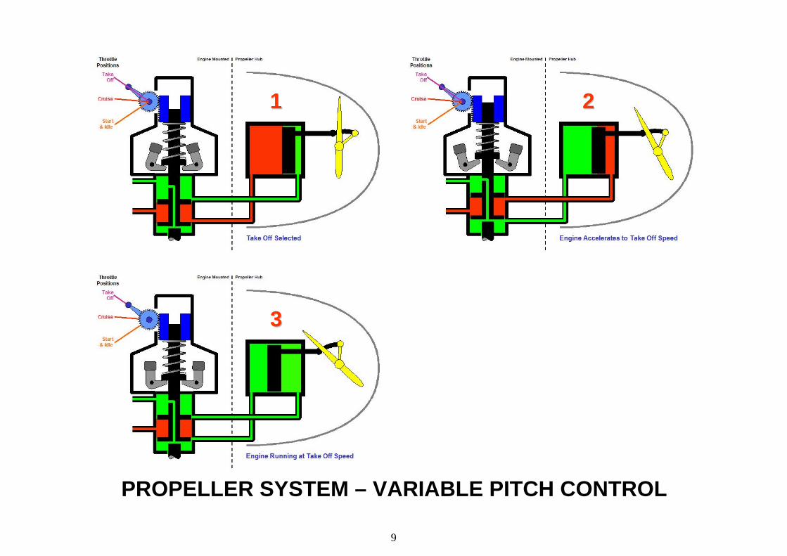
PROPELLER CONTROL – Accelerate to Take-off RPMSequence of Events Follow the numbered illustrations below. Stage 1 – Engine at Idle, Throttle Opened to Take Off
Position. Moving the throttle to the take off position loads the PCU spring tension, this pushes the hydraulic direction valve down to hold the propeller at the fine position. This aids acceleration as it minimises the drag from the propeller, using less fuel and strain on the engine. Stage 2 – Accelerating to Take off RPM During acceleration, the propeller angle lags behind the actual rpm it would be at for the fuel flow delivered at that point. This keeps the hydraulic direction valve in the fine pitch open position. At some stage of the acceleration, the engine will momentarily overspeed, opening the coarse pitch port. At this stage the propeller coarsens off, increasing rotational drag and will therefore slow the engine down until the bob weight centrifugal force equals the PCU spring tension. The overspeed and coarsening of the propeller happens repeatedly until take off rpm is reached. Stage 3 – at Take Off RPM Again the hydraulic direction valve is in the balanced position, preventing hydraulic pressure getting to or leaving the propeller hub piston. This hydraulically locks the propeller in the takeoff angle.
As the brakes are released and the aircraft gathers speed, the pitch will gradually increase to maintain the correct angle of attack for the propeller. This happens because forward speed relieves the drag on the propeller allowing it to be driven faster by the engine, but as the engine overspeeds slightly the propeller is forced to a coarser pitch, thereby restoring the engine rpm. The Rolls-Royce Dart Turboprop engine take off speed is 15000 rpm with an absolute overspeed limit of 15050 rpm, at which point fuel flow is automatically limited to prevent higher rpm. This equates to 0.3% increase in speed over take off speed. The sensitivity of the spring verses the bob weight force is such that only minor variations in engine rpm will result in the adjustment of the propeller pitch.
9
PROPELLER SYSTEM – VARIABLE PITCH CONTROL
11 22
33
10
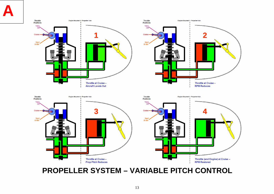
PROPELLER CONTROL – Cruise RPM - Aircraft Level to Dive Sequence of Events Follow the numbered illustrations below. Stage 1 – Aircraft in Straight and Level Flight With the aircraft flying straight and level, the pitch is hydraulically locked at the cruise angle. The only control input to take place now is the aircraft is manoeuvred into a dive attitude, the engine controls are not altered. Stage 2 – Dive Initiated When the aircraft is flown into the dive attitude it will gather speed, an increase in forward speed relieves the drag on the propeller allowing it to be driven faster by the engine. As the engine overspeeds slightly the propeller moves to a coarser pitch by the bob weight force overcoming the PCU spring force, the hydraulic direction valve directs hydraulic pressure to the coarse side of the piston. Stage 3 – Dive Attitude The pitch is coarsened off to maintain the correct angle of attack for the propeller, thereby restoring the engine rpm. In the steady state condition, the hydraulic direction valve is back in the balanced position locking the propeller in the correct angle for the aircraft/flight situation
Control System Overview For whatever reason the engine rpm changes (flight attitude or power demand changes) the sequence of events in the control system are as follows: - 1. RPM change upsets the balance between the bob weights
and the PCU spring. 2. As a result the hydraulic direction valve is moved to allow
hydraulic pressure to change the propeller pitch. 3. The propeller pitch changes the bob weight force back to
balance the PCU spring. 4. RPM is restored, and the hydraulic direction valve is in the
balanced position.

11
PROPELLER SYSTEM – VARIABLE PITCH CONTROL
11 22
33 44

12
PROPELLER CONTROL – Cruise RPM - Aircraft Dive to Level OutSequence of Events Stage 1 Aircraft in dive The propeller blade the pitch is hydraulically locked at the cruise angle. Stage 2 Levelling out Rpm reduces due to the increase drag of the propeller blades at the dive blade angle. Stage 3 The propeller pitch is fined off to increase rpm to the controlled value.
13
PROPELLER SYSTEM – VARIABLE PITCH CONTROL
11 22
33 44
A