chapter 1 specifications of hg2g - idec global€¦ · 1-1 chap.1 chapter 1 specifications of hg2g...
TRANSCRIPT

1-1
Chap.1
Chapter 1 Specifications of HG2G
1 Product List................................................................................................1-2 1.1 Main Unit..................................................................................................................... 1-2 1.2 Accessories ................................................................................................................... 1-2 1.3 Options ......................................................................................................................... 1-2
2 Part names and Functions.........................................................................1-3 2.1 Layout of Touch Switches ........................................................................................... 1-4
3 Main Unit Specifications ............................................................................1-5 3.1 Applicable Standards .................................................................................................. 1-5 3.2 General Specifications................................................................................................. 1-5 3.3 External Dimensions................................................................................................... 1-7 3.4 Function Specifications ............................................................................................... 1-8 3.5 Display Specifications ................................................................................................. 1-9 3.6 Operation Specifications ........................................................................................... 1-10 3.7 Power supply Input Specifications ........................................................................... 1-10 3.8 Serial Interface1 Specifications ................................................................................ 1-11 3.9 Serial Interface2 Specifications ................................................................................ 1-12 3.10 O/I link Interface Specifications ............................................................................. 1-13 3.11 Ethernet (LAN) Interface Specifications................................................................ 1-13
4 Installation and Wiring .............................................................................1-14 4.1 Installation Location ................................................................................................. 1-14 4.2 Installation................................................................................................................. 1-15 4.3 Wiring......................................................................................................................... 1-16
5 Inspection ................................................................................................1-17

Chapter1 Specifications of HG2G
1-2
1 Product List
1.1 Main Unit
Main Unit
Display Type
Interface Type No.
RS232C/485(422) Ethernet
HG2G-SB22TF-* Mono chrome
RS232C/485(422) HG2G-SB22VF-*RS232C/485(422) Ethernet
HG2G-SS22TF-* Color
RS232C/485(422) HG2G-SS22VF-*
*: Main Unit Color B: Dark gray W: Light gray S: Silver (Unapproved by UL)
1.2 Accessories
Mounting Clip (4)
Host communication plug (1) (Attached to the Main Unit)
Instruction Sheet (Japanese/English) 1 each
1.3 Options
Configuration software (WindO/I-NV2)
Type No. Description HG9Y-B595 Japanese manual HG9Y-B596 English manual HG9Z-ZSS2W CD-ROM
Maintenance Cable
Type No. Description HG9Z-XCM22 2m D-sub 9P socket
(PC side) for PC
Mounting Clip
Type No. Description SLD-K02PN10 Mounting clip (SLD-K02),
10 pieces per package
PLC Connecting Cable
Type No. Description HG9Z-XC275 For IDEC・ONC, MicroSmart,
Mitsubishi FX series, etc. 5m length
FC2A-KP1C For IDEC・ONC, MicroSmart, Mitsubishi FX series, etc. 2.4m length
Protective Sheet
Type No. Description HG9Z-2D2 5-sheets per package
O/I Link Unit
Type No. Description HG9Z-2G1 Dedicated communication unit
Replacement Battery
Type No. Description HG9Z-XR1 Coin-type lithium
primary battery, CR2032
Host I/F
Type No. Description HG9Z-XT09 Host communication plug (1)

2 Part names and Functions
1-3
Chap.1
2 Part names and Functions
No. Name Description 1 Display (5.7 inch STN LCD) 2 Touch Panel
(Analog resistance membrane method)
3 Status LED 4 Serial Interface 1 Detachable 9P terminal block 5 Serial Interface 2 Mini-DIN 8P connector 6 O/I Link Interface 3P terminal block 7 Ethernet interface RJ-45 connector 8 Terminating Resistor Selector Switch For RS422/485 interface 9 Battery Holder Cover
10 Mounting Clip Position 11 Gasket

Chapter1 Specifications of HG2G
1-4
2.1 Layout of Touch Switches
Touch switches can be placed on the WindO/I-NV2 grids. The physical switch layout is as shown in the illustration below.
• For the initial settings of the analog touch panel, refer to Chapter 33 "2.1.2 Initialize" in the "MICRO/I HG2G, HG1F/2F/2S/3F/4F Instruction Manual".
• When more than one button is pressed, the touch screen will not be able to detect such operation. Instead, the center point between buttons pressed in the display area will be triggered. This is due to the detection characteristics of the analog touch panel. When more than one button is pressed simultaneously, the resulting operation may vary.
1
1
100
300 320
240

2 Main Unit Specifications
1-5
Chap.1
3 Main Unit Specifications
3.1 Applicable Standards
Refer to “Instruction Sheet”.
3.2 General Specifications
Electrical Specifications
Rated Operating Voltage
24VDC
Power Voltage Range
85% to 120% of rated voltage (including ripple)
Power Consumption
10W maximum
Allowable Momentary Power Interruption
10ms maximum, Level PS-2 (IEC/EN61131)
Inrush Current 20A maximum Dielectric Strength 1000VAC 10mA, 1 minute
(between power terminals and FG)
Insulation Resistance
50 MΩ minimum (500V DC megger) (between power terminals and FG)
Backup Battery Built-in CR2032 lithium primary battery Standard replacement cycle: 4 years Guaranteed term: 1 year (at 25°C)
Environmental Specifications
Operating Ambient Temperature
0 to 50°C (no freezing)
Operating Relative Humidity
10 to 90%RH (no condensation)
Storage Ambient Temperature
-20 to 60°C (no freezing)
Storage Relative Humidity
10 to 90%RH (no condensation)
Altitude 0 to 2000m (operation), 0 to 3000m (transportation) (IEC61131-2)
Vibration Resistance (Damage Limits)
5 to 9 Hz, amplitude 3.5 mm 9 to 150 Hz, 9.8 m/s2 X, Y, Z directions for 10 cycles [100 minutes] (IEC60068-2-6)
Shock Resistance(Damage Limits)
147 m/s2, 11 ms [5 shocks each in 3 axes] (IEC60062-2-27)
Pollution Degree 2 (IEC60664-1) Corrosion Immunity
Free from corrosive gases
Effect of Incorrect Connection
Reversal of DC power supply polarity
No damage but the equipment will not operate
Connection to Power supply that exceeds ratings
Permanent failure likely
Earthing
Function earth Wiring to ensure stable equipment operation
Chapter1 Specifications of HG2G
1-6
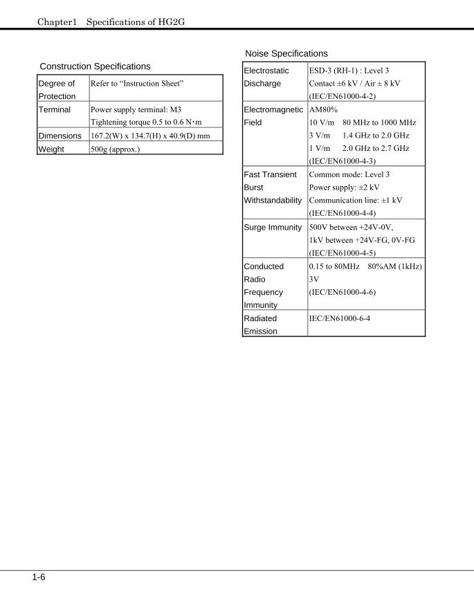
Construction Specifications
Degree of Protection
Refer to “Instruction Sheet”
Terminal Power supply terminal: M3 Tightening torque 0.5 to 0.6 N・m
Dimensions 167.2(W) x 134.7(H) x 40.9(D) mm Weight 500g (approx.)
Noise Specifications
Electrostatic Discharge
ESD-3 (RH-1) : Level 3 Contact ±6 kV / Air ± 8 kV (IEC/EN61000-4-2)
Electromagnetic Field
AM80% 10 V/m 80 MHz to 1000 MHz 3 V/m 1.4 GHz to 2.0 GHz 1 V/m 2.0 GHz to 2.7 GHz (IEC/EN61000-4-3)
Fast Transient Burst Withstandability
Common mode: Level 3 Power supply: ±2 kV Communication line: ±1 kV (IEC/EN61000-4-4)
Surge Immunity 500V between +24V-0V, 1kV between +24V-FG, 0V-FG (IEC/EN61000-4-5)
Conducted Radio Frequency Immunity
0.15 to 80MHz 80%AM (1kHz)3V (IEC/EN61000-4-6)
Radiated Emission
IEC/EN61000-6-4

3 Main Unit Specifications
1-7
Chap.1
3.3 External Dimensions

Chapter1 Specifications of HG2G
1-8
3.4 Function Specifications
Number of screens
Base Screens: 3,000 screens Popup Screens: 3,015 screens
Screen memory
Approx. 1Mbyte max. (Flash memory)
Screen types Base Screen, Popup Screen, System Screen
Number of parts
480/screen (Base Screen) 480/screen (Popup screen)
Number of host devices
256 read, 512 write/screen (Base Screen) 64 read, 128 write/screen (Popup Screen)
Parts Bit Button Word Button Goto Screen Button Print Button Key Button Multi Button Keypad Selector Switch Potentiometer Numerical Input Character Input Pilot Lamp Multi-State Lamp Picture Display Message Display Message Switching Display Alarm List Display Alarm Log Display Numerical Display Bar Graph Trend Chart Pie Chart Meter Calendar Bit Write Command Word Write Command Goto Screen Command Print Command Screen Script Command
Multi Command Timer
Operation modes
Run Mode: Normal operation
Data Transfer Mode: Data upload and download
System Mode: Initial setting, clock setting, system information, self diagnosis and debug
Screen creation andoperation settings
WindO/I-NV2 software application
Calendar Year, Month, Day, Hour, Min., Sec. and Day-of-week +/-30 sec. per month (at 25°C)
Power failuremaintenance
Maintenance object: Calendar, Alarm Log Data: 1024points (max.), Data Log Data: approx. 13808 points (max.), and 8192 keep internal relay/8192 resister

3 Main Unit Specifications
1-9
Chap.1
3.5 Display Specifications
Display Functions
Color 5.7 inch STN color LCD (transparent type)
Display
Monochrome 5.7 inch STN monochromeLCD (transparent type)
Effective display area 117.2 (W) x 88.4 (H) mm Display resolution 320 (W) x 240 (H) dots Pixel pitch 0.36 (W) x 0.36 (H) mm
Color 256 Display colors Monochrome 2 Contrast adjustment Can be adjusted from the
front touch panel
Size/number 1/4 size: 8 x 8 dots/ 40 characters x 30 lines 1/2 size: 8 x 16 dots/ 40 characters x 15 lines Full size: 16 x 16 dots/ 20 characters x 15 lines Double size: 32 x 32 dots/10 characters x 7.5 lines
Character Display
Types
8 x 8 dots, 8 x 16 dots: English, Katakana, Symbols (JIS8 bit code), ISO-8859-1(European), ANSI1250(Central European), ANSI1257(Baltic), ANSI1251(Cyrillic) 16 x 32 dots, 24 x 48dots, 32 x 64 dots: ISO-8859-1(European) 16 x 16 dot: Japanese: 1st and 2nd level JIS, Chinese, Korean, Taiwanese 32 x 32 dots: Japanese: 1st and 2nd standard JIS
Character attributes
Magnification: 0.5, 1, 2, 3, 4and 8 (ver. and hor.) Attributes: Blink, reverse, bold, embossed
Types Line, rectangle, Polyline polygon, circle, ellipse, pie,arc, polygon (3, 4, 5, 6, and 8 sided), bitmap image and paint
Line types Solid, dotted, dashed, longdashed, long dashed dot and long dashed dot dot
Line width 1,2,3 and 5 dots
Graphics Display
Graphic symbol attribute
Blink switch display between specified colors (1 or 0.5 second period)
Backlight
Light Source Cold-cathode tube Presumed Life Of Back Light
Standard 75,000 hours* *Luminance drop to half after continuous lighting at room temperature
Replacement Impossible Control Auto off
The backlight is not replaceable. If the backlight has burned out, contact our sales office.

Chapter1 Specifications of HG2G
1-10
3.6 Operation Specifications
Touch Switches
Switch mechanism Touch switches Switch method Analog resistance film typeOperation force 0.2 to 0.8N Life 1,000,000 cycles min. Confirmation Electronic buzzer
3.7 Power supply Input Specifications
Wiring UL1007 AWG18 to AWG22 Recommended Pressure Terminal 1Cable: AI 0.34 -6TQ*
AI 0.5 -8WH* AI 0.75 -8GY* AI 1 -8RD*
2Cable: AI-TWIN 2 x 0.5-8WH* *Phoenix Contact Maintain separation between the input wiring and the power, output and communications wiring.
Connector Pin Layout
Connector Pin Functions
Symbol Function + Power supply 24V DC - Power supply 0V
Functional Earth
Ground the Functional Earth terminal to ensure stable operation.
+
-

3 Main Unit Specifications
1-11
Chap.1
3.8 Serial Interface1 Specifications
RS-232C
Electrical characteristics
EIA RS-232C compliant
Transmission speed
1200, 2400, 4800, 9600, 19200, 38400, 57600 and 115200bps
Synchronization Asynchronous Communication method
Half or full duplex
Control system Hardware control/none Protocol (1) PLC-link protocol for a variety
of PLCs and communicationunits
(2) DM Link Transmission distance
15m (5m when connected to a PLC programming port)
Connection format
1:1
RS-485 (422) Electrical characteristics
EIA RS-485 (422) compliant
Transmission speed
1200, 2400, 4800, 9600, 19200, 38400, 57600 and 115200bps (MPI only) 187500 bps
Synchronization Asynchronous Communication method
Half or full duplex
Control system Hardware control/none Protocol (1) PLC-link protocol for a variety
of PLCs and communicationunits
(2) DM Link Transmission distance
300m (5m when connected to a PLC programming port)
Connection format
1:1 or 1:N
Only one of the RS-232C or RS-485 (422) ports can be used at one time. If both interfaces are connected it may cause interference between the units. Only connect the interface that will be used.
Connector
Connector D-sub 9P connector (socket)
Connecting and disconnecting cycles
500 cycles (min.)
Connector Pin Layout
Connector Pin Functions
No. Name I/O Function Communication
type
1 SD OUT Send Data 2 RD IN Receive data 3 RS OUT Request to send 4 CS IN Clear to Send
5 SG - Signal Ground R
S-23
2C
6 SDA OUT Send Data (+) 7 SDB OUT Send Data (-) 8 RDA IN Receive data (+) 9 RDB IN Receive data (-)
R
S-48
5 (4
22)

Chapter1 Specifications of HG2G
1-12
Terminating Resistance Selector Switch
When the RS-485(422) interface is used for serial interface 1, setting the Terminating Resistance Selector Switch to the ON side will connect the terminating resistance (100 Ω) between RDA and RDB.
3.9 Serial Interface2 Specifications
Electrical characteristics
EIA RS-232C compliant
Transmission speed 9600, 19200, 38400, 57600 and 115200 bps
Synchronization Asynchronous Communication method Half duplex Protocol Dedicated protocol Connector Mini DIN8P connector Connection and disconnection cycles
500 cycles (min.)
Connector Pin Layout
Connector Pin Functions
No. Name I/O Function 1 RS OUT Request to send 2 ER OUT Data terminal ready 3 SD OUT Send data 4 RD IN Receive data 5 DR IN Data set ready 6 EN IN Cable recognition 7 SG - Signal ground 8 NC - No connection
Do not connect pin 6 (EN) with any other pins except when performing maintenance communications for downloading project data.
6
3
4
78
5
2 1
ON OFF
3 Main Unit Specifications
1-13
Chap.1
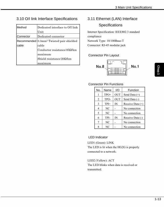
3.10 O/I link Interface Specifications
Method Dedicated interface to O/I link Unit
Connector Dedicated connector Recommended cable
0.3mm2 Twisted-pair shielded cable Conductor resistance:85Ω/km maximum Shield resistance:20Ω/km maximum
3.11 Ethernet (LAN) Interface
Specifications
Internet Specification: IEEE802.3 standard compliance Network Type: 10/100Base-T Connector: RJ-45 modular jack
Connector Pin Layout
Connector Pin Functions
No. Name I/O Function 1 TPO+ OUT Send Data (+) 2 TPO- OUT Send Data (-) 3 TPI+ IN Receive Data (+) 4 NC - No connection 5 NC - No connection 6 TPI- IN Receive Data (-) 7 NC - No connection 8 NC - No connection
LED Indicator
LED1 (Green): LINK The LED is lit when the HG2G is properly connected to a network. LED2 (Yellow): ACT The LED blinks when data is received or transmitted.

Chapter1 Specifications of HG2G
1-14
4 Installation and Wiring Be aware of the following when mounting the HG2G Series main unit and wiring it to the host unit.
4.1 Installation Location
Operating Environmental Considerations
To ensure reliable and safe operation of the equipment, avoid the types of installation locations listed below.
・ Places where there is a lot of dust, salt or iron
filings.
・ Places where the equipment will be splashed
with chemicals.
・ Places where the equipment will be exposed to
direct sunlight.
・ Places where strong ultraviolet rays fall on the
HG2G.
・ Places where corrosive or flammable gasses
are present.
・ Places where vibration will be directly
transmitted to the equipment.
・ Places where condensation may occur due to
sudden temperature changes.
・ Places where high-voltage or arc-generating
equipment (electromagnetic contactors or
circuit protectors) exists in the vicinity.
Ambient temperature considerations
・ Allow sufficient space for ventilation, and install
the equipment away from heat sources.
・ Allow at least 100mm between the HG2G and
walls or other equipment.
・ If installing the HG2G in a location where the
ambient temperature will exceed the allowed
rating, install cooling fans or air-conditioning
equipment.
・ The HG2G has been designed to use natural
airflow for cooling when installed vertically. If
you install it using any other orientation, use
forced-air cooling, or lower the ambient
operating temperature.
・ At temperatures over the rated operating
temperature, the clock accuracy is affected.
Adjust the clock before use.

4 Installation and Wiring
1-15
Chap.1
4.2 Installation
Place the HG2G in a panel cut-out and fasten with the attached mounting clips at four places to a specified torque of 0.12 to 0.15 N ・ m (Recommended torque: 0.14 N・m) uniformly. Do not tighten excessively, otherwise the HG2G may warp and cause wrinkle on the display, or impair the waterproof characteristics. Take into consideration the viewing angle and switch operation factors when choosing the installation height.
If the mounting clips are tightened obliquely to the panel, the HG2G may fall off the panel.
When installing the HG2G into a panel cut-out, make sure that the gasket is not twisted. Especially when re-installing, take special care because any twists in the gasket will impair the waterproof characteristics.
Panel Cut-out Dimensions [Dimension: mm]
121+
2
153.0+2
Panel Thickness: 1.6 to 5 Mounting clip
Mounting clip
Panel

Chapter1 Specifications of HG2G
1-16
4.3 Wiring
Wiring Considerations
・ Do not install the HG2G close to high-voltage or
arc-generating equipment (such as circuit
breakers etc.).
・ Install the unit at least 200mm from the high
input voltage of the power supply.
・ In the case of DC power supply models, keep
the distance between the unit and the power
supply as short as possible.
・ Use separate power supplies and wiring for
electromotive equipment and I/O equipment.
・ A host connection cable is provided with the
equipment. Please specify your requirement.
・ If you will use your own cable for connecting to
the host, ensure that the connector and wiring
are of the recommended type. Also, do not
exceed the recommended length for the
cable.
Wiring to the Power Supply Terminals
・ Terminal No. allocation is as follows.
Symbol Function + Power supply 24V DC - Power supply 0V
Functional Earth
・ Use Phoenix Contact AI Series bar-type
pressure contact terminals.
・ The tightening torque range is 0.5N.m to
0.6N.m.
・ Twist the AWG18 (1mm2) to AWG22 (0.34mm2)
power supply wires as tightly together as
possible, and keep the wiring distance
between the power supply and the unit as
short as possible.
・ Use separate power supplies and wiring for
electromotive equipment and I/O equipment.
・ For safety, earth the Function earth terminal of
the unit.
・ When exporting the HG2G to Europe, use an
EN60127 (IEC60127) approved fuse or an
EU-approved circuit protector.
Wiring Serial Interface 1
・ The appropriate connector is the recommended
connector (connector: JBZ-25P-90(JST),
cover: J-C25-C2(JST)).
・ Perform the wiring in accordance with the
requirements of the communication method.
This will minimize the influence of external
electrical noise and electrical noise generated
by the wiring itself. EMC evaluation has not
been done for the cables.
・ Use shielding for the cables, and install line
clamp filters near each end of the cable.
+ -

5 Inspection
1-17
Chap.1
5 Inspection Periodically inspect the HG2G to keep it in the best operating condition at all times.
・ The HG2G display screen and protective sheet
are easily damaged. Never attempt to operate
the unit with tools or other hard objects.
・
・ To clean the display screen, wipe it with a soft
cloth moistened with a mild detergent or
alcohol. Never attempt to clean the display screen
using paint thinner, ammonia, strong acid, strong alkaline, or other powerful solvents.
・ Terminals and connectors
Check for loose screws, loose connectors and
damaged wiring.
・ Installation
Make sure that all mounting clips and screws
are tightened sufficiently. If the mounting clips
are loose, tighten the screw to the
recommended tightening torque.