chapter 1 general introduction 3 - kinco … - ks105... · 2.2.7 data retentive and data backup ......
TRANSCRIPT

KKKKincoincoincoinco-K-K-K-KSSSS seriesseriesseriesseries
1
CONTENTCONTENTCONTENTCONTENT
CHAPTER 1 GENERAL INTRODUCTION.............................................................................. 3
1.1 SUMMARY............................................................................................................................3
1.2 PRODUCT LIST..................................................................................................................... 3
1.3 ENVIRONMENTAL CONDITION............................................................................................. 4
CHAPTER 2 CPU MODULE INTRODUCTION....................................................................... 5
2.1 OVERVIEW........................................................................................................................... 5
2.1.1 Structure....................................................................................................................... 5
2.1.2 CPU Types.................................................................................................................... 5
2.2 FUNCTIONS.......................................................................................................................... 7
2.2.1 CPU Status and LEDs...................................................................................................7
2.2.2 Programming port and serial port................................................................................. 8
2.2.3 CAN port...................................................................................................................... 9
2.2.4 Expansion modules.......................................................................................................9
2.2.5 High Speed Counter and High Speed Pulse Output......................................................9
2.2.6 Edge Interrupts............................................................................................................. 9
2.2.7 Data Retentive and Data Backup................................................................................ 10
2.2.8 Real-time Clock (RTC)...............................................................................................10
2.2.9 Backup Battery........................................................................................................... 11
2.3 WIRING DIAGRAM..............................................................................................................12
2.4 DIMENSION........................................................................................................................ 15
2.5 TECHNICAL SPECIFICATION................................................................................................15
CHAPTER 3 SOFTWARE INTRODUCTION..........................................................................16
2.1 OVERVIEW......................................................................................................................... 16
KKKKincoincoincoinco-K-K-K-KSSSS seriesseriesseriesseries
2
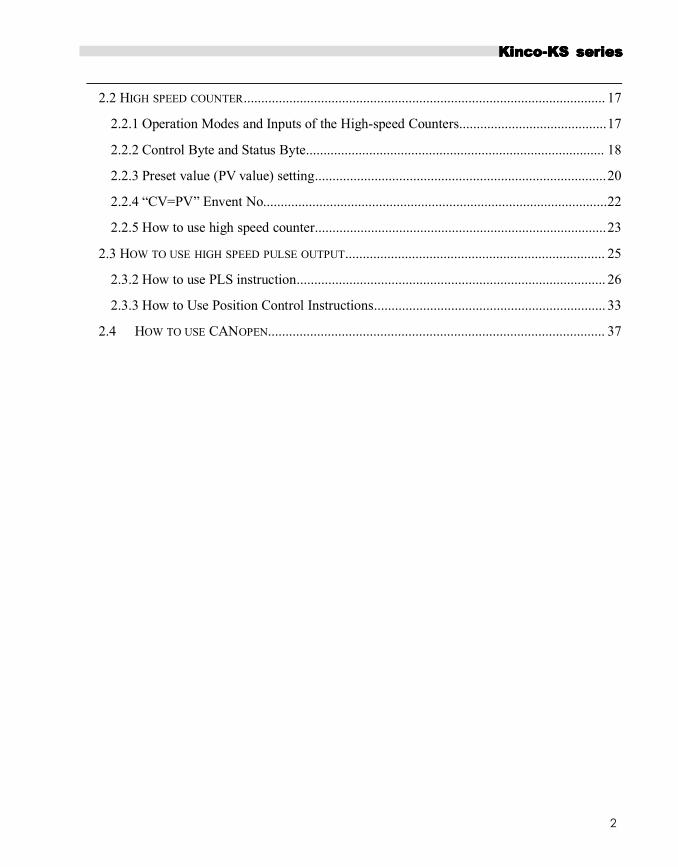
2.2 HIGH SPEED COUNTER....................................................................................................... 17
2.2.1 Operation Modes and Inputs of the High-speed Counters..........................................17
2.2.2 Control Byte and Status Byte..................................................................................... 18
2.2.3 Preset value (PV value) setting...................................................................................20
2.2.4 “CV=PV” Envent No..................................................................................................22
2.2.5 How to use high speed counter...................................................................................23
2.3 HOW TO USE HIGH SPEED PULSE OUTPUT.......................................................................... 25
2.3.2 How to use PLS instruction........................................................................................ 26
2.3.3 How to Use Position Control Instructions.................................................................. 33
2.4 HOW TO USE CANOPEN................................................................................................ 37

KKKKincoincoincoinco-K-K-K-KSSSS seriesseriesseriesseries
3
Chapter 1 General Introduction
1.11.11.11.1 SummarySummarySummarySummary
Kinco-K5 series PLC is a small and integrated PLC .It is Kinco new thin and high performance PLC.
Based on high performance, high reliability and powerful functions of K5/K2, KS series use higher level
CPU. KS has CANopen port, higher speed input and output, small size for installation.
It can fit more user’s requirement.
1.21.21.21.2 ProductProductProductProduct ListListListList
NameNameNameName OrderOrderOrderOrder No.No.No.No. DescriptionDescriptionDescriptionDescription
CPUCPUCPUCPUModuleModuleModuleModule
CPU105
KS105-16DT
DC 24V, DI 8*DC24V,DO 8*DC24V.
1* RS232(programming port),1*RS485.
Expandable(max 14 modules)
KS105C1-16DTDC 24V, DI 8*DC24V,DO 8*DC24V
1* RS232(programming port),1*RS485,1*CAN
KS105C2-16DT
DC 24V, DI 8*DC24V,DO 8*DC24V
1* RS232(programming port),1*RS485,2*CAN
Expandable(max 14 modules)
1.31.31.31.3 EnvironmentalEnvironmentalEnvironmentalEnvironmental ConditionConditionConditionCondition
Kinco-KS accords with GB/T 15969.3-2007(idt IEC61131-2:2007)standard and test specifications.
The following table lists the conditions and requirements for Kinco-KS to work properly. It is the user's
responsibility to ensure that the service conditions are not exceeded.
TransportTransportTransportTransport andandandand storagestoragestoragestorage
Ambient
conditions
temperature -40 --- +70 °C
relative humidity 10%~95%, no condensation

KKKKincoincoincoinco-K-K-K-KSSSS seriesseriesseriesseries
4
Altitude Up to 3000 m
Mechanical
conditionsFree falls With manufacturer's original packaging, 5 falls from 1m of height.
Normal Operation
Ambient
conditions
air temperature Open equipment : -10 --- +55°C; Enclosed equipment: -10 --- +40°C
relative
humidity10%~95%, no condensation
Altitude Up to 2000 m
Pollution degree for use in pollution degree 2.
Mechanical
conditions
Sinusoidal
vibrations
5<f<8.4Hz, Occasional: 3.5mm amplitude; Continuous: 1.75mm
mplitude.
8.4<f<150, Occasional: 1.0g acceleration; Continuous: 0.5g
acceleration.
Shockoccasional excursions to 15g, 11 ms, half-sine, in each of 3 mutually
perpendicular axes.
Electromagnetic
compatibility
(EMC)
Electrostatic
discharge±4kV Contact, ±8kV Air. Performance criteria B.
High energy
surge
a.c. main power: 2KV CM, 1KV DM;
d.c. main power: 0.5KV CM, 0.5KV DM;
I/Os and Communication port: 1KVCM.
Performance criteria B.
Fast transient
bursts
main power: 2KV, 5KHz. I/Os and Communication port: 1KV,
5KHz.
Performance criteria B.
Voltage drops
and
interruptions
a.c. supply: at 50Hz, 0% voltage for 1 period; 40% voltage for 10
periods; 75% voltage for 20 periods.
Performance criteria A.
Ingress Protection Rating IP20

KKKKincoincoincoinco-K-K-K-KSSSS seriesseriesseriesseries
5
Chapter 2 CPU Module Introduction
2.12.12.12.1 OverviewOverviewOverviewOverview
2.1.12.1.12.1.12.1.1 StructureStructureStructureStructure
2.1.22.1.22.1.22.1.2 CPUCPUCPUCPUTypesTypesTypesTypes
Kinco-KS provides different CPU models with a diversity of features and capabilities, all the CPU use
DC24V power supply. The following table describes main technical data of each CPU model.
Parameters KS105-16DT KS105C1-16DT KS105C2-16DT
Power supply
Rated voltage DC24V
Voltage range DC20.4V-28.8V
I/O
Digital 8*DI / 8*DO
KKKKincoincoincoinco-K-K-K-KSSSS seriesseriesseriesseries
6
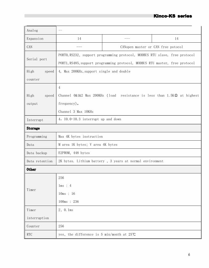
Analog --
Expansion 14 --- 14
CAN --- CANopen master or CAN free potocol
Serial portPORT0,RS232,support programming protocol, MODBUS RTU slave, free protocol
PORT1,RS485,support programming protocol, MODBUS RTU master, free protocol
High speed
counter
4, Max 200KHz,support single and double
High speed
output
4
Channel 0&1&2 Max 200KHz(load resistance is less than 1.5KΩ at highest
frequency)。
Channel 3 Max 10KHz
Interrupt 4,I0.0-I0.3 interrupt up and down
Storage
Programming Max 4K bytes instruction
Data M area 1K bytes;V area 4K bytes
Data backup E2PROM,448 bytes
Data retention 2K bytes. Lithium battery ,3 years at normal environment
Other
Timer
256
1ms :4
10ms :16
100ms :236
Timer
interruption
2,0.1ms
Counter 256
RTC yes,the difference is 5 min/month at 25℃

KKKKincoincoincoinco-K-K-K-KSSSS seriesseriesseriesseries
7
2.22.22.22.2 FunctionsFunctionsFunctionsFunctions
2.2.12.2.12.2.12.2.1 CPUCPUCPUCPU StatusStatusStatusStatus andandandand LEDsLEDsLEDsLEDs
The CPU has two modes: STOP mode and RUN mode.
In RUN mode, the CPU executes the main scan cycle and all interrupt tasks.
In STOP mode, the CPU will set all output channels (including DO and AO) to the known values which are
specified in the [HardwareHardwareHardwareHardware ConfigurationConfigurationConfigurationConfiguration] through Kincobuilder, and only process communication requests
which comes from KincoBuilder software and other Modbus RTU master device.
� ChangeChangeChangeChange CPUCPUCPUCPU statusstatusstatusstatus
Kinco-KS provides two ways for manually changing the CPU status:
Set all switch of CAN port [OFF],then PLC will be in STOP status.if any switch is [ON],PLC will be in RUN
status. (use all 5 switches for KS105,use 1~4 switches for KS105C1,use 1~3 switches for KS105C2.
Using the operation switch (RUN/STOP); Executing [Debug] -> [RUN] or [STOP] menu command in
Kincobuilder.
The following table lists the combined results of these two ways.
OperationOperationOperationOperation SwitchSwitchSwitchSwitch PositionPositionPositionPosition KincoBuilderKincoBuilderKincoBuilderKincoBuilder commandcommandcommandcommand ActualActualActualActual OperationOperationOperationOperation ModeModeModeMode
Some Switch PositionPositionPositionPosition is ON[RUN] RUN
[STOP] STOP
All Switch PositionPositionPositionPosition is OFF[RUN] STOP
[STOP] STOP
Besides, if CPU detects any seriously fault, it will enter STOP status immediately.
� CPUCPUCPUCPU StatusStatusStatusStatus LEDLEDLEDLED
The CPU module provides 4 status LEDs: RUNRUNRUNRUN, STOPSTOPSTOPSTOP, Comm.Comm.Comm.Comm. and Err.Err.Err.Err.
Run,Run,Run,Run, ErrErrErrErr LEDs show the CPU operation status.
【Run】:If CPU is in RUN status,it will turn on. If CPU is in STOP status,it will turn off.
【Err.】:If CPU detects error in user program or module, it will turn on.

KKKKincoincoincoinco-K-K-K-KSSSS seriesseriesseriesseries
8
KS separates errors into three levels: Fatal error, Serious error, Normal error. When CPU detects an
error, it will use different way to handle according to error level and turn on Err LED, then it will save the
error code in sequence for user analysis.
2.2.22.2.22.2.22.2.2 ProgrammingProgrammingProgrammingProgramming portportportport andandandand serialserialserialserial portportportport
KS provides 2 communication ports,PORT1 and PORT2.It supports baudrate up to 115.2kbps.PORT1 can
be used as programming port and also support Modbus RTU slave protocol and free protocol.PORT2
supports Modbus RTU protocol (as a slave or master) and free protocol.
PS232 programming port is in the RJ45 port. Pins and functions as below,
RS232 can’t insert and release with power. So we should turn off power of CPU or PC, otherwise it will
break ports.

KKKKincoincoincoinco-K-K-K-KSSSS seriesseriesseriesseries
9
2.2.2.2.2.2.2.2.3333 CANCANCANCAN portportportport
KS105C1-16DT has 1 CAN port, CAN2.It can support CANopen master and free protocol.
KS105C2-16DT has 2 CAN port,,CAN1 and CAN2. CAN2 can support CANopen master and free
protocol.CAN1 can support free protocol.
2.2.42.2.42.2.42.2.4 ExpansionExpansionExpansionExpansion modulesmodulesmodulesmodules
KS105-16DT has expansion port, it can connect KS series expansion modules
CAN1 port of KS105C2-16DT can work as expansion port, also it support protocol. Users can use them
directly without setup, PLC can identify it automatically.
2.2.52.2.52.2.52.2.5 HighHighHighHigh SpeedSpeedSpeedSpeed CounterCounterCounterCounter andandandand HighHighHighHigh SpeedSpeedSpeedSpeed PulsePulsePulsePulse OutputOutputOutputOutput
KS provides 4 high speed counters (HSC0~HSC3).High speed counter supports multiple modes: single phase,
CW/CCW(Up/Down),AB phase (1 multiplication and 4 multiplication).All can support up to
200KHz(Include single phase and AB phase).
KS provides 4 high speed pulse outputs(Q0.0,Q0.1 and Q0.4, Q0.5).All support PTO and PWM.Q0.0 and
Q0.1 ,Q0.5support up to 200KHz (The resistor of load should be less than 3KΩ),Q0.4 supports up to 10KHz.
2.2.62.2.62.2.62.2.6 EdgeEdgeEdgeEdge InterruptsInterruptsInterruptsInterrupts
I0.0-I0.3 in CPU support edge interrupt function, it can execute interrupt by rising edge and falling edge of
input signal. By using this function, it can capture the rising edge and falling edge of input signal quickly. For
some input signal whose pulse width is less than the CPU scan time, it can respond quickly.
2.2.72.2.72.2.72.2.7 DataDataDataData RetentiveRetentiveRetentiveRetentive andandandand DataDataDataData BackupBackupBackupBackup
Data retentive means the data in RAM can retain after power failure.CPU provides a lithium battery
(Replaceable but un-rechargeable) for data retentive.When CPU loses power, the data in the RAM will be
maintained by the lithium battery, and the retentive ranges will be left unchanged at next power on. Through
[Hardware][Hardware][Hardware][Hardware] configuration in KincoBuilder, user can select the type of data retentive (Such as V,C area) and
the range. The life of battery is 5 years and the retaining duration is 3 years at normal temperature.

KKKKincoincoincoinco-K-K-K-KSSSS seriesseriesseriesseries
10
Data backup is that CPU provides an E2PROM to store data permanently. At power on, the CPU will restore
the data from E2PROM into RAM to execute.
Note:Note:Note:Note: BecauseBecauseBecauseBecause E2PROM has a writing limit of 1 million times, users should avoid to write data into data
backup area frequently.
There are 448 bytes in V area for data backup (VB3648--VB4095),the data in this area will save in E2PROM
automatically.K2 sets VB3648--VB3902 as data backup by default,if user needs to use VB3903--VB4095 for
data backup,it needs to configure in 【PLC hardware configuration】.The configuration interface is as
following figure.
2.2.82.2.82.2.82.2.8 Real-timeReal-timeReal-timeReal-time ClockClockClockClock (RTC)(RTC)(RTC)(RTC)
The real-time clock built in the all CPU modules can provide real-time clock/calendar indication. Users need to
use KincoBuilder【PLC】->【Time of Day Clock...】to set the clock when using RTC first time. Then users can
use real-time clock instructions(READ_RTC、SET_RTC、RTC_W、RTC_R).
After CPU power off, the real-time clock can be maintained by lithium battery. The life of battery is 5 years
and the retaining duration is 3 years at normal temperature.
2.2.92.2.92.2.92.2.9 BackupBackupBackupBackup BatteryBatteryBatteryBattery
KS can use certain specification lithium battery as backup battery. When PLC is power-off, it will use the
backup battery to maintain real-time clock and RAM.
The backup battery is removable, user can replace new battery by themselves when the battery is empty.
The lithium battery is CR2032(3V) with connector. As shown in figure,
user can order the battery separately.

KKKKincoincoincoinco-K-K-K-KSSSS seriesseriesseriesseries
11
2.32.32.32.3WiringWiringWiringWiring diagramdiagramdiagramdiagram

KKKKincoincoincoinco-K-K-K-KSSSS seriesseriesseriesseries
12

KKKKincoincoincoinco-K-K-K-KSSSS seriesseriesseriesseries
13

KKKKincoincoincoinco-K-K-K-KSSSS seriesseriesseriesseries
14
2.42.42.42.4 DimensionDimensionDimensionDimension
2.52.52.52.5 TechnicalTechnicalTechnicalTechnical SpecificationSpecificationSpecificationSpecification
� DI Specifications
Input type Source/Sink
Rated input voltage DC 24V (Max. 30V)
Rated input current 3.5mA@24VDC
Max input voltage of logic 0 [email protected]
Minimum input voltage of logic 1 Common channel:[email protected]
Input filter time delay
· off-to-on
· on-to-off
1.2μs
0.5μs;
Isolation between input and internal circuit
KKKKincoincoincoinco-K-K-K-KSSSS seriesseriesseriesseries
15
· Mode
· Voltage
Opto-electrical isolation
500VAC/1 min
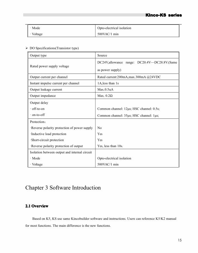
� DO Specifications(Transistor type)
Output type Source
Rated power supply voltageDC24V,allowance range: DC20.4V—DC28.8V.(Same
as power supply)
Output current per channel Rated current:200mA,max.300mA @24VDC
Instant impulse current per channel 1A,less than 1s
Output leakage current Max.0.5цA
Output impedance Max. 0.2Ω
Output delay
· off-to-on
· on-to-off
Common channel: 12μs; HSC channel: 0.5s;
Common channel: 35μs; HSC channel: 1μs;
Protection:
·Reverse polarity protection of power supply
·Inductive load protection
·Short-circuit protection
·Reverse polarity protection of output
No
Yes
Yes
Yes, less than 10s.
Isolation between output and internal circuit
· Mode
· Voltage
Opto-electrical isolation
500VAC/1 min
Chapter 3 Software Introduction
2.12.12.12.1 OverviewOverviewOverviewOverview
Based on K5, KS use same Kincobuilder software and instructions. Users can reference K5/K2 manual
for most functions. The main difference is the new functions.

KKKKincoincoincoinco-K-K-K-KSSSS seriesseriesseriesseries
16
2.22.22.22.2 HighHighHighHigh speedspeedspeedspeed countercountercountercounter
KS provides 4 high speed counters HSC0-HSC3.All can support up to 200KHz
High speed counter supports multiple modes: single phase, CW/CCW,AB phase (1 multiplication and 4
multiplication).
All high speed counter can support maximum 32 PV and support 32 “CV=PV” interrupts. PV can be set as
relative value or absolute value. If it is relative value,
2.2.12.2.12.2.12.2.1 OperationOperationOperationOperationModesModesModesModes andandandand InputsInputsInputsInputs ofofofof thethethethe High-speedHigh-speedHigh-speedHigh-speed CountersCountersCountersCounters
Input signals of high-speed counter include: clock (input impulse), direction, start and reset.
In different operation modes input signals is different. Please see below:
HSCHSCHSCHSC 0000
ModeModeModeMode DescriptionDescriptionDescriptionDescription I0.1I0.1I0.1I0.1 I0.0I0.0I0.0I0.0 I0.5I0.5I0.5I0.5
0Single-phase up/down counter
with internal direction control: SM37.3Clock1 Reset
2 Reset Start
3 Single-phase up/down counter
with external direction controlClock
Direction
4 Reset Direction
6Two-phase counter with up/down clock
inputsClock Down Clock Up
9 A/B phase quadrature counter Clock A Clock B
HSC1HSC1HSC1HSC1
ModeModeModeMode DescriptionDescriptionDescriptionDescription I0.4I0.4I0.4I0.4 I0.6I0.6I0.6I0.6 I0.3I0.3I0.3I0.3 I0.2I0.2I0.2I0.2
0Single-phase up/down counter
with internal direction control: SM47.3Clock1 Reset
2 Reset Start
3 Single-phase up/down counter
with external direction controlClock
Direction
4 Reset Direction
6 Two-phase counter
with up/down clock inputs
Clock
DownClock Up
7 Reset
KKKKincoincoincoinco-K-K-K-KSSSS seriesseriesseriesseries
17
9A/B phase quadrature counter Clock A Clock B
10 Reset
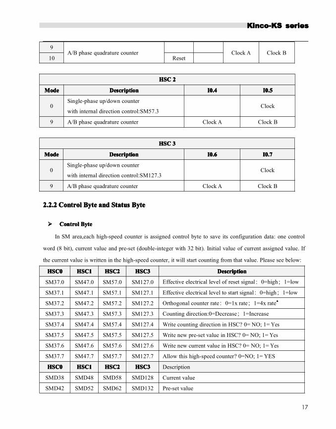
HSCHSCHSCHSC 2222
ModeModeModeMode DescriptionDescriptionDescriptionDescription I0.4I0.4I0.4I0.4 I0.5I0.5I0.5I0.5
0Single-phase up/down counter
with internal direction control:SM57.3Clock
9 A/B phase quadrature counter Clock A Clock B
HSCHSCHSCHSC 3333
ModeModeModeMode DescriptionDescriptionDescriptionDescription I0.6I0.6I0.6I0.6 I0.7I0.7I0.7I0.7
0Single-phase up/down counter
with internal direction control:SM127.3Clock
9 A/B phase quadrature counter Clock A Clock B
2.2.22.2.22.2.22.2.2 ControlControlControlControl ByteByteByteByte andandandand StatusStatusStatusStatus ByteByteByteByte
���� ControlControlControlControl ByteByteByteByte
In SM area,each high-speed counter is assigned control byte to save its configuration data: one control
word (8 bit), current value and pre-set (double-integer with 32 bit). Initial value of current assigned value. If
the current value is written in the high-speed counter, it will start counting from that value. Please see below:
HSC0HSC0HSC0HSC0 HSC1HSC1HSC1HSC1 HSC2HSC2HSC2HSC2 HSC3HSC3HSC3HSC3 DescriptionDescriptionDescriptionDescription
SM37.0 SM47.0 SM57.0 SM127.0 Effective electrical level of reset signal:0=high;1=low
SM37.1 SM47.1 SM57.1 SM127.1 Effective electrical level to start signal:0=high;1=low
SM37.2 SM47.2 SM57.2 SM127.2 Orthogonal counter rate:0=1x rate;1=4x rate****
SM37.3 SM47.3 SM57.3 SM127.3 Counting direction:0=Decrease;1=Increase
SM37.4 SM47.4 SM57.4 SM127.4 Write counting direction in HSC? 0= NO; 1= Yes
SM37.5 SM47.5 SM57.5 SM127.5 Write new pre-set value in HSC? 0= NO; 1= Yes
SM37.6 SM47.6 SM57.6 SM127.6 Write new current value in HSC? 0= NO; 1= Yes
SM37.7 SM47.7 SM57.7 SM127.7 Allow this high-speed counter? 0=NO; 1= YES
HSC0HSC0HSC0HSC0 HSC1HSC1HSC1HSC1 HSC2HSC2HSC2HSC2 HSC3HSC3HSC3HSC3 Description
SMD38 SMD48 SMD58 SMD128 Current value
SMD42 SMD52 SMD62 SMD132 Pre-set value

KKKKincoincoincoinco-K-K-K-KSSSS seriesseriesseriesseries
18
HSC0HSC0HSC0HSC0 HSC1HSC1HSC1HSC1 HSC2HSC2HSC2HSC2 HSC3HSC3HSC3HSC3 DescriptionDescriptionDescriptionDescription
SM141.0 SM151.0 SM161.0 SM171.0 Use multiple preset value:0=No. 1=Yes.
SM141.1 SM151.1 SM161.1 SM171.1Preset value type:0=Absolute value. 1=Relative
value.
SM141.2 SM151.2 SM161.2 SM171.2
Preset value comparison interrupt (“CV=PV”) cyclic
execution.
0=No. 1=Yes.
Note:Only valid when preset value is relative value.
SM141.3 SM151.3 SM161.3 SM171.3 Reserved
SM141.4 SM151.4 SM161.4 SM171.4Update multiple PV segment and preset value:0=No.
1=Yes
SM141.5 SM151.5 SM161.5 SM171.5 Reset interrupt variable:0=Yes. 1=No.
SM141.6 SM151.6 SM161.6 SM171.6 Reserved
SM141.7 SM151.7 SM161.7 SM171.7 Reserved
HSC0HSC0HSC0HSC0 HSC1HSC1HSC1HSC1 HSC2HSC2HSC2HSC2 HSC2HSC2HSC2HSC2 DescriptionDescriptionDescriptionDescription
SMW142 SMW152 SMW162 SMW172Starting value of preset value table ( It is offset
corresponding to VB0),it must be odd value.
It needs to pay attention that not all the control bits of the control byte is suitable for all operation mode. For
example, “Counting direction” and “Write counting direction in HSC” can be only used in mode 0,1 and 2
(Single-phase up/down counter
with internal direction control),if the operation mode is with external direction control, then these two bits
will be ignored.
The control byte, current value and preset value are 0 by default after power on.
� StatusStatusStatusStatus ByteByteByteByte
In SM area, each high-speed counter has a status byte, which indicates the current status of high speed
counter.
HSC0HSC0HSC0HSC0 HSC1HSC1HSC1HSC1 HSC2HSC2HSC2HSC2 HSC3HSC3HSC3HSC3 DescriptionDescriptionDescriptionDescription
SM36.0 SM46.0 SM56.0 SM126.0 Reserved
SM36.1 SM46.1 SM56.1 SM126.1 Reserved
SM36.2 SM46.2 SM56.2 SM126.2 Reserved
SM36.3 SM46.3 SM56.3 SM126.3 Fault in multiple PV value table:0=No,1=Yes

KKKKincoincoincoinco-K-K-K-KSSSS seriesseriesseriesseries
19
SM36.4 SM46.4 SM56.4 SM126.4 Reserved
SM36.5 SM46.5 SM56.5 SM126.5Current counting direction:
0 = Down; 1= Up
SM36.6 SM46.6 SM56.6 SM126.6Current value equal to preset value:
0 = No,1 = Yes
SM36.7 SM46.7 SM56.7 SM126.7Current value greater than preset value:
0 = No,1 = Yes
HSC0 HSC1 HSC2 HSC3 Description
SMB140 SMB150 SMB160 SMB170 Current PV segment No.(Start from 0)
2.2.32.2.32.2.32.2.3 PresetPresetPresetPreset valuevaluevaluevalue (PV(PV(PV(PV value)value)value)value) settingsettingsettingsetting
KS supports up to 32 PV value for each high speed counter, and supports setting PV value as relative value or
absolute value. It supports “CV=PV” interrupt cyclic execution.
Follows take HSC0 as example to describe PV value function and setting.
���� HowHowHowHow totototo selectselectselectselect ““““multiplemultiplemultiplemultiple PVPVPVPV”””” modemodemodemode
In the control byte of each high speed counter, there is one control bit for enable multiple preset value.
In HSC0, this control bit is SM141.0.
If SM141.0 is 0,it will use single PV value, same as K5 PLC.SMD42 is for new PV value,SM37.5 is to
update this new PV value.
If SM141.0 is 1,it will use multiple PV values. In this situation,SM37.5 and SMD42 is invalid. All the PV
values will be in the PV table(SMW142 is for starting address of the table),SM141.4 defines whether it use
the data in PV table or not.If SM141.4 is 1,it means when HSC starts, it will get the data from PV table. If
SM141.4 is 0,when HSC starts,it will ignore the data in PV table and get the data from last preset value.
���� MultipleMultipleMultipleMultiple PVPVPVPV tabletabletabletable
If using PV table,all the PV value will get from PV table.
Each HSC provides one control word which is used to set the starting address of PV table.If using multiple
PV,then all PV value will get from PV table.The starting address of PV table is odd address of V area,such as
301(Means VB301).
The format of PV table is as follows.
KKKKincoincoincoinco-K-K-K-KSSSS seriesseriesseriesseries
20
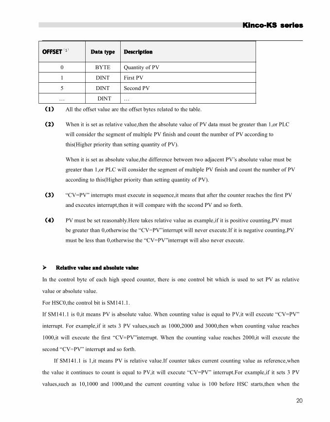
OFFSETOFFSETOFFSETOFFSET(1) DataDataDataData typetypetypetype DescriptionDescriptionDescriptionDescription
0 BYTE Quantity of PV
1 DINT First PV
5 DINT Second PV
… DINT …
(1111) All the offset value are the offset bytes related to the table.
(2222) When it is set as relative value,then the absolute value of PV data must be greater than 1,or PLC
will consider the segment of multiple PV finish and count the number of PV according to
this(Higher priority than setting quantity of PV).
When it is set as absolute value,the difference between two adjacent PV’s absolute value must be
greater than 1,or PLC will consider the segment of multiple PV finish and count the number of PV
according to this(Higher priority than setting quantity of PV).
(3333) “CV=PV” interrupts must execute in sequence,it means that after the counter reaches the first PV
and executes interrupt,then it will compare with the second PV and so forth.
(4444) PV must be set reasonably.Here takes relative value as example,if it is positive counting,PV must
be greater than 0,otherwise the “CV=PV”interrupt will never execute.If it is negative counting,PV
must be less than 0,otherwise the “CV=PV”interrupt will also never execute.
���� RelativeRelativeRelativeRelative valuevaluevaluevalue andandandand absoluteabsoluteabsoluteabsolute valuevaluevaluevalue
In the control byte of each high speed counter, there is one control bit which is used to set PV as relative
value or absolute value.
For HSC0,the control bit is SM141.1.
If SM141.1 is 0,it means PV is absolute value. When counting value is equal to PV,it will execute “CV=PV”
interrupt. For example,if it sets 3 PV values,such as 1000,2000 and 3000,then when counting value reaches
1000,it will execute the first “CV=PV”interrupt. When the counting value reaches 2000,it will execute the
second “CV=PV” interrupt and so forth.
If SM141.1 is 1,it means PV is relative value.If counter takes current counting value as reference,when
the value it continues to count is equal to PV,it will execute “CV=PV” interrupt.For example,if it sets 3 PV
values,such as 10,1000 and 1000,and the current counting value is 100 before HSC starts,then when the

KKKKincoincoincoinco-K-K-K-KSSSS seriesseriesseriesseries
21
counting value reaches 110,1110 and 2110,it will execute corresponding“CV=PV” interrupt.
���� ““““CV=PVCV=PVCV=PVCV=PV””””interruptinterruptinterruptinterrupt cycliccycliccycliccyclic executionexecutionexecutionexecution
“CV=PV”interrupt cyclic execution is only valid when PV is set as relative value.
If SM141.0 is 0,it means “CV=PV” interrupt only executes once.When all interrupts finish execution,then it
will stop.If it needs to execute again, it must modify the related registers and execute HSC instruction again.
If SM141.0 is 1,it means “CV=PV” interrupt is cyclic execution.When the last PV interrupt finishes
execution,PLC will take the current counting value as reference to calculate new value for PV interrupt,then
it will start to compare the counting value and execute “CV=PV” interrupt and so forth.This process will
execute cyclically.
For example,it sets 3 PV values,such as 10,1000 and 1000.And the current counting value is 100 before HSC
starts,then the value for every interrupt is as following table.
CurrentCurrentCurrentCurrent countingcountingcountingcounting
valuevaluevaluevalue
InterruptInterruptInterruptInterrupt timestimestimestimes FirstFirstFirstFirst valuevaluevaluevalue SecondSecondSecondSecond valuevaluevaluevalue ThirdThirdThirdThird valuevaluevaluevalue
100 1st time 110 1110 2110
2110 2nd time 2120 3120 4120
4120 3rd time 4130 5130 6130
… N time … … …
2.2.42.2.42.2.42.2.4 ““““CV=PVCV=PVCV=PVCV=PV”””” EnventEnventEnventEnvent No.No.No.No.
When it uses single PV mode, the HSC will be fully compatible with K5 (Include “CP=PV” event No.).
When it uses multiple PV mode, the HSC will assign a new event No. for 32 PV, as shown in following table.
HighHighHighHigh speedspeedspeedspeed
countercountercountercounter
InterruptInterruptInterruptInterrupt No.No.No.No. DescriptionDescriptionDescriptionDescription
HSC0
64 “CV=PV”interrupt of 1st PV
65 “CV=PV”interrupt of 2nd PV
… …(Plus 1)
95 “CV=PV”interrupt of 32nd PV
HSC1
96 “CV=PV”interrupt of 1st PV
97 “CV=PV”interrupt of 2nd PV
… …(Plus 1)
127 “CV=PV”interrupt of 32nd PV
HSC2 128 “CV=PV”interrupt of 1st PV

KKKKincoincoincoinco-K-K-K-KSSSS seriesseriesseriesseries
22
129 “CV=PV”interrupt of 2nd PV
… …(Plus 1)
159 “CV=PV”interrupt of 32nd PV
HSC3
160 “CV=PV”interrupt of 1st PV
161 “CV=PV”interrupt of 2nd PV
… …(Plus 1)
191 “CV=PV”interrupt of 32nd PV
2.2.52.2.52.2.52.2.5 HowHowHowHow totototo useuseuseuse highhighhighhigh speedspeedspeedspeed countercountercountercounter
���� MethodMethodMethodMethod 1:Use1:Use1:Use1:Use instructionsinstructionsinstructionsinstructions forforforfor programmingprogrammingprogrammingprogramming
1)Configure the control byte of HSC and define the current value (i.e. starting value) and the preset value.
2)Use HDEF instruction to define the counter and its operation mode.
3)(Optional) Use ATCH instruction to define the interrupt routines.
4)Use HSC instruction to start the high-speed counter.
���� MethodMethodMethodMethod 2:Use2:Use2:Use2:Use wizardwizardwizardwizard ofofofof HSCHSCHSCHSC
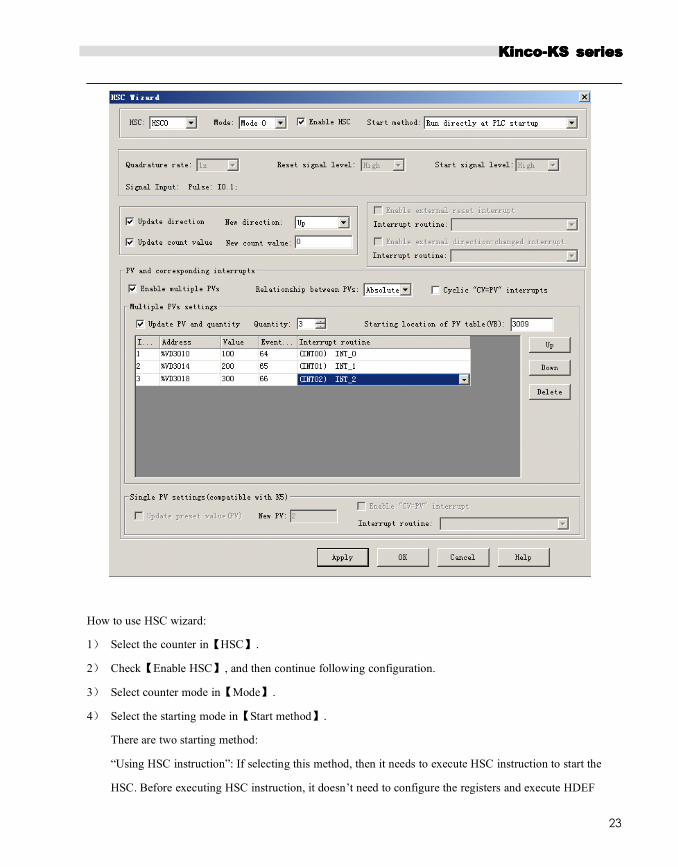
In K2 PLC, it provides configuration wizard for high speed counter. Users can use the wizard to configure all
high speed counters and don’t need to program. The wizard is as following figure:
After using wizard to configure HSC, user also can use “MMMMethodethodethodethod 1111” to modify the parameters of HSC.
KKKKincoincoincoinco-K-K-K-KSSSS seriesseriesseriesseries
23
How to use HSC wizard:
1) Select the counter in【HSC】.
2) Check【Enable HSC】, and then continue following configuration.
3) Select counter mode in【Mode】.
4) Select the starting mode in【Start method】.
There are two starting method:
“Using HSC instruction”: If selecting this method, then it needs to execute HSC instruction to start the
HSC. Before executing HSC instruction, it doesn’t need to configure the registers and execute HDEF

KKKKincoincoincoinco-K-K-K-KSSSS seriesseriesseriesseries
24
instruction.
“Run directly at PLC startup”: If selecting this method, then the HSC will start automatically after PLC
power on without executing any instructions.
5) If user needs to use multiple PV mode, then check【Enable multiple PVs】and continue to configure all
PV values and related ‘Value’ and ‘Interrupt subroutine’. If checking【Update PV and quantity】, then
it can adjust the value in【Quantity】to modify the number of PV.
6) If user needs to use single PV mode, then check【Update preset value(PV)】 in ‘Single PV settings’ and
modify the PV value and related interrupt subroutine.
7) For other options, please refer to the descriptions to HSC.
2.32.32.32.3 HowHowHowHow totototo useuseuseuse highhighhighhigh speedspeedspeedspeed pulsepulsepulsepulse outputoutputoutputoutput
Kinco-KS provides 4 channels for high speed pulse output, they are Q0.0,Q0.1 and Q0.4,Q0.5.All support
PT0 and PWM output.
. Q0.0 and Q0.1,0.4 support maximum 200KHz, and Q0.5supports maximum 10KHz.
KS have one direction output channel for every high speed output. KS provide 1 direction enable control in
SM area.
Q0.0 Q0.1 Q0.4 Q0.5
Direction output
channel
Q0.2 Q0.3 Q0.6 Q0.7
Direction enable
Control
SM201.3 SM231.3 SM251.3 SM221.3
Direction output channel output motor direction control signal, corotation output 0,inversion output 1.
Direction enable control can forbid or allow direction output channel. It is highest primary.
If it is forbidden, it won’t output direction control signal. The channel will work as common DO.
2.3.1 High speed pulse output instruction
KS provides 3types of instructions for high speed pulse output.
1) PLS: it is used to output PTO(Single segment or multiple segments) and PWM.
2222) Position control: There are 5 instructions, include PREL(Relative positioning), PABS(Absolute
KKKKincoincoincoinco-K-K-K-KSSSS seriesseriesseriesseries
25
positioning) ,PHOME(Homing), PJOG(Jogging) and PSTOP(Emergency stop). User can use these
instructions to achieve positioning control easily .Note:Note:Note:Note: WhenWhenWhenWhen usingusingusingusing positionpositionpositionposition controlcontrolcontrolcontrol instructions,instructions,instructions,instructions, thethethethe
frequencyfrequencyfrequencyfrequency ofofofof outputoutputoutputoutput pulsepulsepulsepulse mustmustmustmust bebebebe notnotnotnot lesslesslessless thanthanthanthan 125Hz.125Hz.125Hz.125Hz.
3) Following instruction PFLO_F: There are parameters such as input frequency(F),electronic gear
ratio(NUME、DENOM), pulse number(COUNT) and so on, these parameters can be used as variable.
The frequency of pulse output is equal to F multiple by electronic gear ratio. When the pulse number
reaches the value COUNT, then it will stop output and set DONE bit. Note:Note:Note:Note: WhenWhenWhenWhen usingusingusingusing followingfollowingfollowingfollowing
instruction,instruction,instruction,instruction, thethethethe frequencyfrequencyfrequencyfrequency ofofofof outputoutputoutputoutput pulsepulsepulsepulse mustmustmustmust bebebebe notnotnotnot lesslesslessless thanthanthanthan 30Hz.30Hz.30Hz.30Hz.
2.3.22.3.22.3.22.3.2 HowHowHowHow totototo useuseuseuse PLSPLSPLSPLS instructioninstructioninstructioninstruction
PLS instruction can implement PTO and PWM output function.
• PTO:Pulse Train Output.
• PWM:Pulse-Width Modulation.
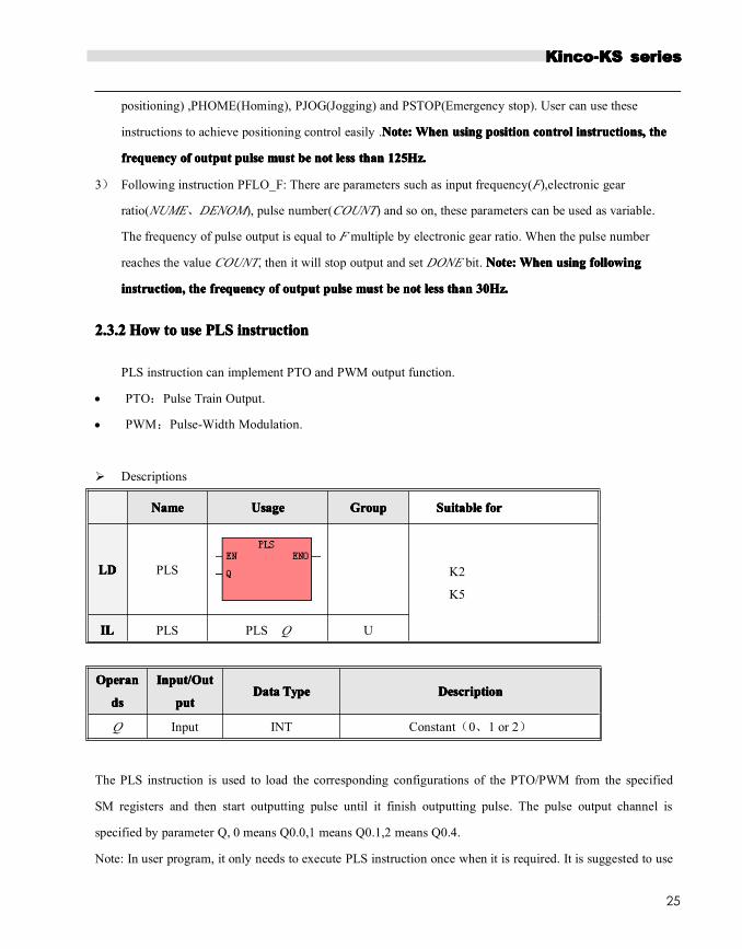
� Descriptions
NameNameNameName UsageUsageUsageUsage GroupGroupGroupGroup SuitableSuitableSuitableSuitable forforforfor
LDLDLDLD PLS K2
K5
ILILILIL PLS PLS Q U
OperanOperanOperanOperan
dsdsdsds
Input/OutInput/OutInput/OutInput/Out
putputputputDataDataDataData TypeTypeTypeType DescriptionDescriptionDescriptionDescription
Q Input INT Constant(0、1 or 2)
The PLS instruction is used to load the corresponding configurations of the PTO/PWM from the specified
SM registers and then start outputting pulse until it finish outputting pulse. The pulse output channel is
specified by parameter Q, 0 means Q0.0,1 means Q0.1,2 means Q0.4.
Note: In user program, it only needs to execute PLS instruction once when it is required. It is suggested to use

KKKKincoincoincoinco-K-K-K-KSSSS seriesseriesseriesseries
26
edge instruction to execute PLS instruction. If executing PLS executing all the time, then it can’t output
normally.
• LDLDLDLD
If EN is 1,then PLS is executed.
• ILILILIL
If CR is 1,then PLS is executed. It won’t influence the value of CR.
2.3.2.12.3.2.12.3.2.12.3.2.1 High-speedHigh-speedHigh-speedHigh-speed PulsePulsePulsePulse OutputOutputOutputOutput FunctionFunctionFunctionFunction
The Kinco-KS provides 4 PTO/PWM pulse generators that can be used to output PTO/PWM. Thereof, one
generator is assigned to Q0.0, called PWM0 or PTO0; the second one is assigned to Q0.1, called PWM1 or
PTO1,and the third one is assigned to Q0.4,called PWM2 or PTO2. The forth one is assigned to Q0.5,called
PWM3 or PTO3.
The PTO/PWM pulse generators and the DO mapping area share the memory address Q0.0 ,Q0.1 and Q0.4、
Q0.5. When the user program executes the high speed pulse output instructions, then the PTO/PWM generator
controls the output and prohibits the normal use of this output channel.
Notice: Make sure not to use the PTO and PWM functions if Q0.0 ,Q0.1 and Q0.4 ,Q0.5 are
relay-output!
���� PWMPWMPWMPWM
PWM provides a continuous pulse output with a variable duty cycle, and you can control the cycle time and the
pulse width.
The unit of cycle time and pulse width time is microsecond(us) or millisecond(ms). The maximum value of
cycle time is 65535. If the pulse width time is greater than the cycle time value, the duty cycle is set to be
100% automatically and the output is on continuously. If the pulse width time is 0, the duty cycle is set to be
0% and the output is off.
���� PTOPTOPTOPTO

KKKKincoincoincoinco-K-K-K-KSSSS seriesseriesseriesseries
27
PTO provides a square wave (50% duty cycle) output, and you can control the cycle time and the number of
the output pulses. The unit of cycle time is microsecond(us) or millisecond(ms).The maximum value of cycle
time is 65535.The range of pulse number is 2~4,294,967,295.If the specified pulse number is less than 2, then
KInco-KS will set related error bit and prohibit the output.
PTO function provides single segment of pulse and multiple segment of pulse.
• SingleSingleSingleSingle segmentsegmentsegmentsegment pulsepulsepulsepulse
In single segment pulse mode, it only executes pulse train output once after executing PLS instruction.
• MultipleMultipleMultipleMultiple segmentsegmentsegmentsegment pulsepulsepulsepulse
In multi-segment pulse mode, CPU automatically reads the configurations of each PTO segment from a
profile table located in V area and executes the related PTO segment.
The length of each segment is 8 bytes, including a cycle time value (16-bit, WORD), a reserved value (It
is not used now,16-bit, INT), and a pulse number value (32-bit, DWORD).Thereof, all the pulse output
frequency are the same in same segment. It uses PLS instruction to start multiple segment pulse.
In this mode, the starting address of the profile table is stored in SMW168 (corresponding to PTO0) ,SMW178
(corresponding to PTO1) and SMW268(corresponding to PTO2).Time base is configured by SM67.3
(corresponding to PTO0) ,SM77.3 (corresponding to PTO1) and SM87.3 (corresponding to PTO2). The time
base can be in either microsecond or millisecond. All cycle values in the profile table must use same time base,
and cannot be modified when the profile is executing.
The following table describes the format of the profile table.
ByteByteByteByte offsetoffsetoffsetoffset1111 LengthLengthLengthLength SegmentSegmentSegmentSegment DescriptionDescriptionDescriptionDescription
0 8-bit The number of segments (1 to 64)
1 16-bit
1
Initial cycle time (2 to 65535 times of the time base)
3 16-bit Reserved
5 32-bit Pulse number(1 to 4,294,967,295)
9 16-bit
2
Initial cycle time (2 to 65535 times of the time base)
11 16-bit Reserved
13 32-bit Pulse number(1 to 4,294,967,295)

KKKKincoincoincoinco-K-K-K-KSSSS seriesseriesseriesseries
28
… … …
1111All the offsets in this column are relative to the starting position of the profile table.
Notice: the starting position of the profile table must be an odd address in V area, e.g. VB3001.
2.3.2.22.3.2.22.3.2.22.3.2.2 PTO/PWMPTO/PWMPTO/PWMPTO/PWM RegisterRegisterRegisterRegister
Each PTO/PWM generator is provided with some registers in SM area to store its configurations, as shown in
following table.
Q0.0Q0.0Q0.0Q0.0 Q0.1Q0.1Q0.1Q0.1 Q0.4Q0.4Q0.4Q0.4 Q0.4Q0.4Q0.4Q0.4 DescriptionDescriptionDescriptionDescription
SM67.0 SM77.0 SM97.0 SM107.0 PTO/PWMWhether to update the cycle time:
0 = No; 1 = Yes
SM67.1 SM77.1 SM97.1 SM107.1 PWMWhether to update pulse width time::0=No;
1=Yes
SM67.2 SM77.2 SM97.2 SM107.2 PTOWheter to update the pulse number::0=No;
1=Yes
SM67.3 SM77.3 SM97.3 SM107.3 PTO/PWM Time base: 0=1μs;1=1ms
SM67.4 SM77.4 SM97.4 SM107.4 PWM
Update method:
0 = asynchronous update; 1 = synchronous
update
SM67.5 SM77.5 SM97.5 SM107.5 PTOOperation mode:
0 = single segment; 1 = multiple segment
SM67.6 SM77.6 SM97.6 SM107.6 Function selection: 0= PTO;1=PWM
SM67.7 SM77.7 SM97.7 SM107.7 PTO/PWM Enable/disable: 0=disable;1= enable
Q0.0Q0.0Q0.0Q0.0 Q0.1Q0.1Q0.1Q0.1 Q0.4Q0.4Q0.4Q0.4 DescriptionDescriptionDescriptionDescription
SMW68 SMW78 SMW98 SMW108 PTO/PWM Cycle time , Range:2~65535
SMW70 SMW80 SMW100 SMW110 PWM Pulse width, Range: 0~65535
SMD72 SMD82 SMD102 SMD112 PTO Pulse number, Range:1~4,294,967,295
SMW168SMW17
8SMW218 SMW248
The starting location of the profile table (byte offset from
V0)For multi-segment PTO operation only
All the default value for control byte, cycle time and pulse number are 0.The way to modify configuration of
PTO/PWM is that configure related control registers first, if it is PTO multiple segment pulse, it also needs to

KKKKincoincoincoinco-K-K-K-KSSSS seriesseriesseriesseries
29
configure profile table, and then execute PLS instruction.
Each PTO/PWM generator also provides a status bytes in SM area, user can get the status information of
PTO/PWM generator from the status bytes, as shown in following table.
Q0.0Q0.0Q0.0Q0.0 Q0.1Q0.1Q0.1Q0.1 Q0.4Q0.4Q0.4Q0.4 Q0.Q0.Q0.Q0.5555 DescriptionDescriptionDescriptionDescription
SM66.0 SM76.0 SM96.0 SM106.0 Reserved
SM66.1 SM76.1 SM96.1 SM106.1 Reserved
SM66.2 SM76.2 SM96.2 SM106.2 Reserved
SM66.3 SM76.3 SM96.3 SM106.3 PWM idle: 0=No, 1=Yes
SM66.4 SM76.4 SM96.4 SM106.4
Whether the cycle time or pulse number of PTO is
wrong: 0=No, 1=Yes
Note:Note:Note:Note: CycleCycleCycleCycle timetimetimetime andandandand pulsepulsepulsepulse numbernumbernumbernumber mustmustmustmust bebebebe greatergreatergreatergreater
thanthanthanthan 1.1.1.1.
SM66.5 SM76.5 SM96.5 SM106.5PTO profile terminated due to user command:
0=No, 1=Yes
SM66.6 SM76.6 SM96.6 SM106.6 Reserved
SM66.7 SM76.7 SM96.7 SM106.7 PTO idle: 0=No, 1=Yes
The PTO idle bit or PWM idle bit indicate the completion of the PTO or PWM output.
2.3.3.32.3.3.32.3.3.32.3.3.3 PTOPTOPTOPTO OperationsOperationsOperationsOperations
The fallowing takes PTO0 as an example to introduce how to configure and operate the PTO/PWM generator
in the user program.
There are two procedures for using PTO: Configure related control registers and initialize PTO. Execute PLS
instruction.
Use SM0.1 (the first scan memory bit) to call a subroutine that contains the initialization instructions. Since
SM0.1 is used, the subroutine shall be executed only once, and this reduces CPU scan time and provides a
better program structure.
���� ExecuteExecuteExecuteExecute thethethethe PTOPTOPTOPTO (Single-Segment(Single-Segment(Single-Segment(Single-Segment Operation)Operation)Operation)Operation)
1) Set control byte SMB67 according to the desired operation.
For example, SMB67 = B#16#85 indicates:
• Enable the PTO/PWM function

KKKKincoincoincoinco-K-K-K-KSSSS seriesseriesseriesseries
30
• Select PTO operation
• Select 1μs as the time base
• Allow updating the pulse number and cycling time.
2) Set SMW68 according to desired cycle time.
3) Set SMD72 according to desired pulse number.
4) (Optional) use ATCH to attach the PTO0-complete event (event 28) to an interrupt routine to respond
in real time to a PTO0-complete event.
5) Execute the PLS instruction to configure PTO0 and start it.
���� ChangingChangingChangingChanging thethethethe PTOPTOPTOPTO CycleCycleCycleCycle TimeTimeTimeTime (Single-Segment(Single-Segment(Single-Segment(Single-Segment Operation)Operation)Operation)Operation)
Follow these steps to change the PTO cycle time.
1) Set control byte SMB67 according to the desired operation.
For example, SMB67 = B#16#81 indicates:
• Enable the PTO/PWM function
• Select PTO operation
• Select 1μs as the time base
• Allow updating the cycle time value.
2) Set SMW68 according to desired cycle time.
3) Execute the PLS instruction to configure PTO0 and start it, then a new PTO with the updated cycle time
shall be generated.
���� ChangingChangingChangingChanging thethethethe PTOPTOPTOPTO PulsePulsePulsePulse Number(Single-SegmentNumber(Single-SegmentNumber(Single-SegmentNumber(Single-Segment Operation)Operation)Operation)Operation)
Follow these steps to change the PTO pulse count:
1) Set control byte SMB67 according to the desired operation.
For example, SMB67 = B#16#84 indicates:
• Enable the PTO/PWM function
• Select PTO operation

KKKKincoincoincoinco-K-K-K-KSSSS seriesseriesseriesseries
31
• Select 1μs as the time base
• Allow updating the pulse number
2) Set SMD72 according to desired pulse number.
3) Execute the PLS instruction to configure PTO0 and start it, then a new PTO with the updated pulse
number shall be generated.
���� ExecuteExecuteExecuteExecute thethethethe PTOPTOPTOPTO (Multiple-Segment(Multiple-Segment(Multiple-Segment(Multiple-Segment Operation)Operation)Operation)Operation)
1) Set control byte SMB67 according to the desired operation.
For example, SMB67 = B#16#A0 indicates:
• Enable the PTO/PWM function
• Select PTO operation
• Select multi-segment operation
• Select 1μs as the time base
2) Set an odd number as the starting position of the profile table into SMW168.
3) Use V area to configure the profile table.
4) (Optional) Use ATCH to attach the PTO0-complete event (event 28) to an interrupt routine to respond in
real time to a PTO0-complete event.
5) Execute the PLS instruction to configure PTO0 and start it.
2.3.3.32.3.3.32.3.3.32.3.3.3 PWMPWMPWMPWMOperationsOperationsOperationsOperations
Following takes PWM0 as an example to introduce how to configure and operate the PTO/PWM generator in
the user program.
There are two procedures for using PWM: Configure related control registers and initialize PTO. Execute
PLS instruction.
Use SM0.1 (the first scan memory bit) to call a subroutine that contains the initialization instructions. Since
SM0.1 is used, the subroutine shall be executed only once, and this reduces CPU scan time and provides a
better program structure.

KKKKincoincoincoinco-K-K-K-KSSSS seriesseriesseriesseries
32
���� ExecuteExecuteExecuteExecute PWMPWMPWMPWM
1) Set control byte SMB67 according to the desired operation.
For example, SMB67 = B#16#D3 indicates:
• Enable the PTO/PWM function
• Select PWM operation
• Select 1μs as the time base
• Allow updating the pulse width value and cycle time value
2) Set SMW68 according to desired cycle time.
3) Set SMW70 according to desired pulse width.
4) Execute the PLS instruction to configure PWM0 and start it.
���� ChangingChangingChangingChanging thethethethe PulsePulsePulsePulse WidthWidthWidthWidth forforforfor thethethethe PWMPWMPWMPWMOutputOutputOutputOutput
The following steps describes how to change PWM output pulse width.
1) Set control byte SMB67 according to the desired operation.
For example, SMB67 = B#16#D2 indicates:
• Enable the PTO/PWM function
• Select PWM operation
• Select 1μs as the time base
• Allow updating the pulse width value and cycle time value
2) Set SMW70 according to desired pulse width.
3) Execute the PLS instruction to configure PWM0 and start it.
2.3.32.3.32.3.32.3.3 HowHowHowHow totototo UseUseUseUse PositionPositionPositionPosition ControlControlControlControl InstructionsInstructionsInstructionsInstructions
2.3.3.12.3.3.12.3.3.12.3.3.1 HowHowHowHow totototo ModifyModifyModifyModify thethethethe CurrentCurrentCurrentCurrent ValueValueValueValue ofofofof PositionPositionPositionPosition ControlControlControlControl InstructionsInstructionsInstructionsInstructions
���� ControlControlControlControl RegistersRegistersRegistersRegisters andandandand StatusStatusStatusStatus RegistersRegistersRegistersRegisters
For the Position Control instructions,KS1 specifies a control byte for each high-speed output channel to store

KKKKincoincoincoinco-K-K-K-KSSSS seriesseriesseriesseries
33
its configurations. Besides, it assigns a current value register(DINT) to store the pulse number which has
outputted currently (This value will increase when run forward and decrease when run reverse).The following
table describes the control byte and the current value.
Q0.0 Q0.1 Q0.4 Q0.5 DescriptionDescriptionDescriptionDescription
SMD212 SMD242 SMD262 SMD226
Read only. Current value (Increase when run forward,
decrease when run reverse).It indicates the pulse number
which has already outputted.
SMD208 SMD238 SDM258 SDM222Read/Write. New current value. Use to modify the current
value together with specific control bit.
Q0.0 Q0.1 Q0.4 Q0.4 Description
SM201.7 SM231.7 SM251.7 SM221.7
Read/Write. Emergency-Stop bit.
If this bit is 1, no position control instructions can be
executed.
When executing the PSTOP instruction, this bit is set to 1
automatically, and it must be reset in the program.。
SM201.6 SM231.6 SM251.6 SM221.6
Read/Write. Reset the current value or not
1 --- Clear the current value.
0 --- Maintain the current value.。
SM201.5 SM231.5 SM251.5 SM221.5 Reserved
SM201.4 SM231.4 SM251.4 SM221.4
Read/Write. Use to modify current value.
1 - Modify current value.
0 - Maintain the current value.
SM201.3 SM231.3 SM251.3 SM221.3
Read/Write. Direction control bit.
1 --- Disable the direction output channel, it will be used as
normal output.
0 --- Enable the direction output channel.
SM201.0
~
SM201.2
SM231.0~
SM231.2
SM251.0~
SM251.2
SM221.0~
SM221.2Reserved
���� HowHowHowHow totototo modifymodifymodifymodify currentcurrentcurrentcurrent valuevaluevaluevalue
Each high speed output channel has one register for current value, they are SMD212,SMD242 and
SMD262,SMD226.The outputted pulse number are stored in these registers. Current value registers are read

KKKKincoincoincoinco-K-K-K-KSSSS seriesseriesseriesseries
34
only, if user needs to modify the current value, it can use following methods.
•••• MethodMethodMethodMethod 1111
User reset bit to clear current value.
The reset bits for 4 output channels are SM201.6、SM231.6 、SM251.6 and SM221.6.
When the reset bit is 1, PLC will set the current value as 0.Therefore, t only needs one scan time for the
reset bit to activate. When it needs to use this bit, try to avoid to keep this bit always 1 and also and also
avoid to set this bit while the Position Control instruction (Include PHOME, PREL, PABS, JOG and PFLO_F)
is executing, otherwise the counting value may be wrong.
Following takes channel 0 as example to describe how to reset current value.
(* Network 0 *)
(*Based on homing signal, when it moves to homing, it requires to clear current value*)
LD %SM0.0
PHOME 0, %M0.0, %M0.1, %M0.2, %VW0, %VW2, %VW4, %VD6, %VW10, %M0.4, %M0.5, %MB1
(* Network 1 *)
(*After PHOME finishing, it uses finishing bit “DONE” to clear current value*)
LD %M0.4
R_TRIG
ST %SM201.6
•••• MethodMethodMethodMethod 2222
Modify current value by using following registers.
Q0.0 Q0.1 Q0.4 Q0.5 Description
SMD208 SMD238 SDM258 SDM222Read/Write. New current value. Use to modify the
current value together with specific control bit.
SM201.4 SM231.4 SM251.4 SM221.4
Read/Write. Use to modify current value.
1 - Modify current value.
0 - Maintain the current value. 。
Here takes channel 0 as example to describe the method: If SM201.4 is 0,then it will maintain the current
value SMD212. If SM201.4 is 1, then it will move the value of SMD208 to SMD212.When it needs to use
this bit, avoid to keep this bit always 1 and also avoid to set this bit while the Position Control instruction
(Include PHOME, PREL, PABS, JOG and PFLO_F) is executing, otherwise the counting value may be

KKKKincoincoincoinco-K-K-K-KSSSS seriesseriesseriesseries
35
wrong.
Following takes channel 0 as example to describe how to modify current value:
(* Network 0 *)
(*Based on homing signal, hen it moves to homing, t requires to set current value as 100.*)
LD %SM0.0
PHOME 0, %M0.0, %M0.1, %M0.2, %VW0, %VW2, %VW4, %VD6, %VW10, %M0.4, %M0.5, %MB1
(* Network 1 *)
(*When PHOME instruction finishing, it uses finishing bit DONE to modify current value.*)
LD %M0.4
R_TRIG
MOVE DI#100, %SMD208
ST %SM201.4
2.3.3.22.3.3.22.3.3.22.3.3.2 CanCanCanCan itititit changechangechangechange maximummaximummaximummaximum outputoutputoutputoutput frequencyfrequencyfrequencyfrequency whenwhenwhenwhen positionpositionpositionposition controlcontrolcontrolcontrol instructioninstructioninstructioninstruction isisisis executing?executing?executing?executing?
PREL(Relative position)and PABS(Absolute position) will not change maximum output frequency when
it is executing. It will read the parameters minimum frequency, maximum frequency and
acceleration/deceleration time parameters when it starts, and calculates suitable acceleration/deceleration
segments according to the value of these parameters, then it will start outputting pulse. During pulse
outputting, PREL and PABS will not read the parameters above again, therefore, changing these parameters
will not affect the pulse output.
PJOG(Jogging) will read pulse input frequency(MAXF) all the time when it is executing, and adjust the
pulse output frequency according to new setting frequency.
PHOME(Homing) will read the maximum frequency (MAXF) all the time when it is running at maximum
frequency but hasn’t found homing signal, and calculate acceleration or deceleration segment automatically
according the new setting frequency, then it will accelerate or decelerate to new frequency to output pulse.

KKKKincoincoincoinco-K-K-K-KSSSS seriesseriesseriesseries
36
2.42.42.42.4 HowHowHowHow totototo useuseuseuse CANopenCANopenCANopenCANopen
KS105C1-16DT has 1 CAN port, CAN2
KS105C2-16DT has 2 CAN ports,CAN1 and CAN2.
CAN2 support CANopen master protocol and free protocol.CAN1 support free protocol.
CANopen master function of KS is same as K5 and K2.
For free communication instruction((CAN_INIT、CAN_WRITE、CAN_READ、CAN_RX),CH parameters,0 is
CAN1,1 is CAN2.