chapter 1 drawing sketches for the solid models · chapter 1 drawing sketches for the solid models...
TRANSCRIPT
Chapter 1
Drawing Sketches forthe Solid Models
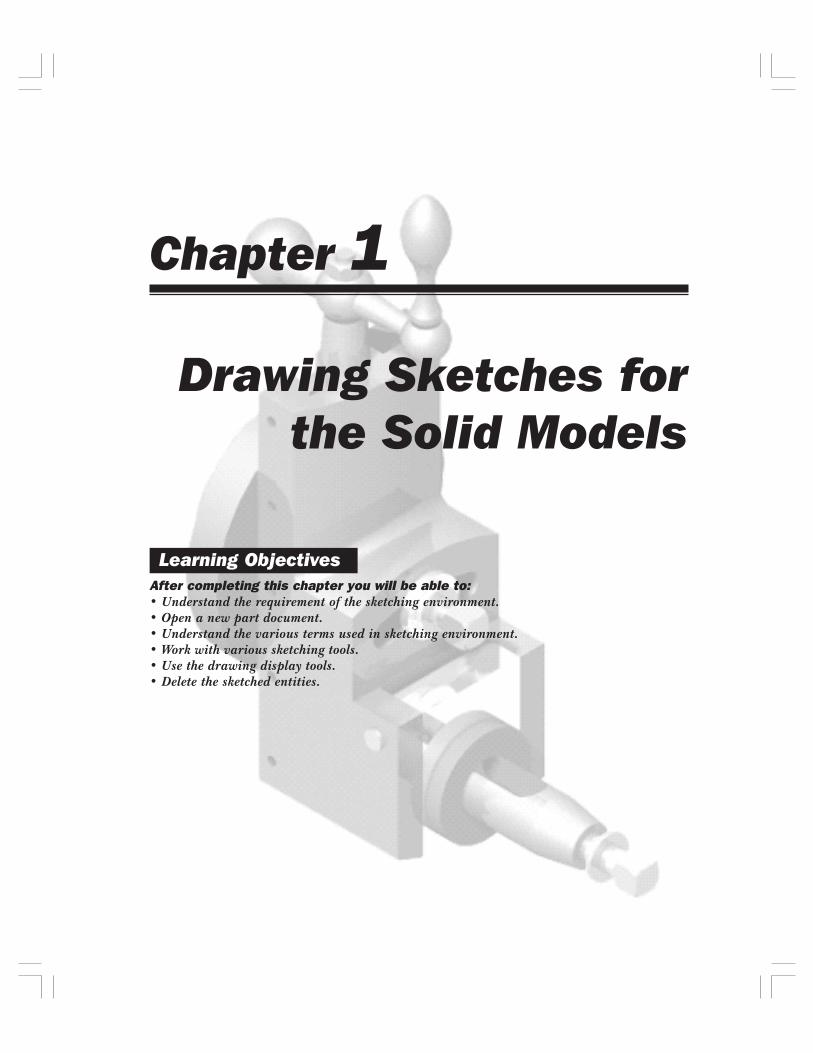
After completing this chapter you will be able to:• Understand the requirement of the sketching environment.• Open a new part document.• Understand the various terms used in sketching environment.• Work with various sketching tools.• Use the drawing display tools.• Delete the sketched entities.
Learning Objectives
1-2 SolidWorks for Designers
THE SKETCHING ENVIRONMENTMost of the products designed using SolidWorks are a combination of sketched features,placed features, and derived features. The placed and derived features are created withoutcreating a sketch, but the sketched features require a sketch to be created first. Generally, thebase feature of any design is a sketched feature and is created using a sketch. Therefore, whilecreating any design, the first and foremost point is to draw the sketch for the base feature.Once you have drawn the sketch of the base feature, you can convert it into the base featureand then add the other sketched, placed, and derived features to complete the design. Inthis chapter, you will learn to create the sketch for the base feature using the various sketcherentities.
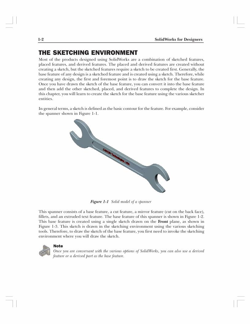
In general terms, a sketch is defined as the basic contour for the feature. For example, considerthe spanner shown in Figure 1-1.
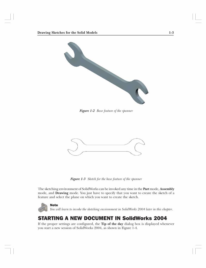
This spanner consists of a base feature, a cut feature, a mirror feature (cut on the back face),fillets, and an extruded text feature. The base feature of this spanner is shown in Figure 1-2.This base feature is created using a single sketch drawn on the Front plane, as shown inFigure 1-3. This sketch is drawn in the sketching environment using the various sketchingtools. Therefore, to draw the sketch of the base feature, you first need to invoke the sketchingenvironment where you will draw the sketch.
NoteOnce you are conversant with the various options of SolidWorks, you can also use a derivedfeature or a derived part as the base feature.
Figure 1-1 Solid model of a spanner
Drawing Sketches for the Solid Models 1-3
The sketching environment of SolidWorks can be invoked any time in the Part mode, Assemblymode, and Drawing mode. You just have to specify that you want to create the sketch of afeature and select the plane on which you want to create the sketch.
NoteYou will learn to invoke the sketching environment in SolidWorks 2004 later in this chapter.
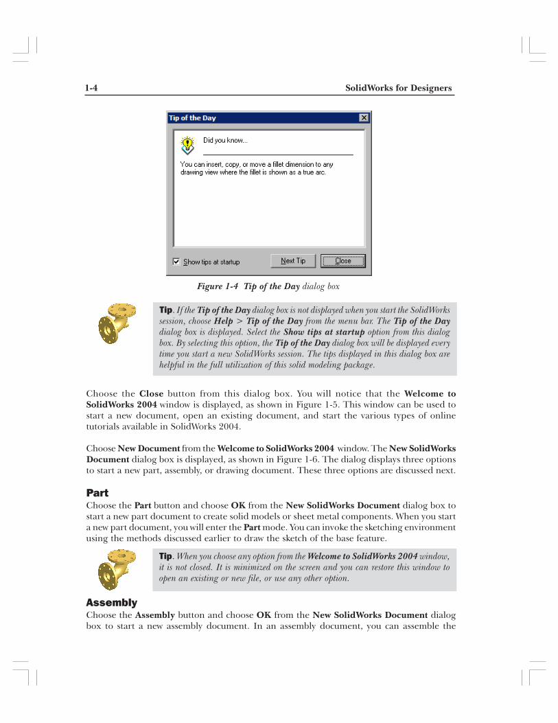
STARTING A NEW DOCUMENT IN SolidWorks 2004If the proper settings are configured, the Tip of the day dialog box is displayed wheneveryou start a new session of SolidWorks 2004, as shown in Figure 1-4.
Figure 1-2 Base feature of the spanner
Figure 1-3 Sketch for the base feature of the spanner
1-4 SolidWorks for Designers
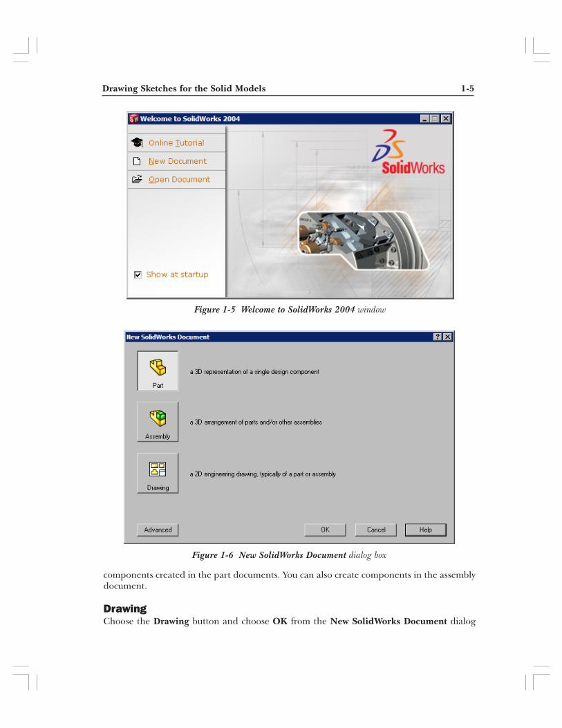
Choose the Close button from this dialog box. You will notice that the Welcome toSolidWorks 2004 window is displayed, as shown in Figure 1-5. This window can be used tostart a new document, open an existing document, and start the various types of onlinetutorials available in SolidWorks 2004.
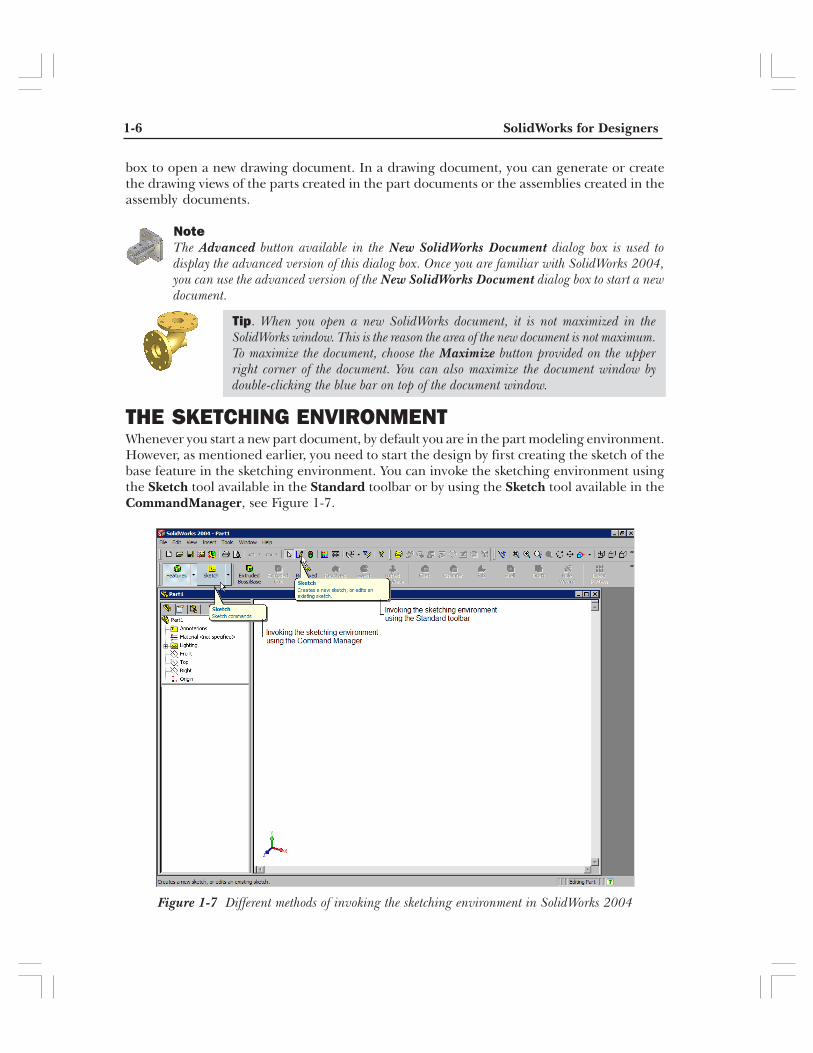
Choose New Document from the Welcome to SolidWorks 2004 window. The New SolidWorksDocument dialog box is displayed, as shown in Figure 1-6. The dialog displays three optionsto start a new part, assembly, or drawing document. These three options are discussed next.
PartChoose the Part button and choose OK from the New SolidWorks Document dialog box tostart a new part document to create solid models or sheet metal components. When you starta new part document, you will enter the Part mode. You can invoke the sketching environmentusing the methods discussed earlier to draw the sketch of the base feature.
AssemblyChoose the Assembly button and choose OK from the New SolidWorks Document dialogbox to start a new assembly document. In an assembly document, you can assemble the
Figure 1-4 Tip of the Day dialog box
Tip. If the Tip of the Day dialog box is not displayed when you start the SolidWorkssession, choose Help > Tip of the Day from the menu bar. The Tip of the Daydialog box is displayed. Select the Show tips at startup option from this dialogbox. By selecting this option, the Tip of the Day dialog box will be displayed everytime you start a new SolidWorks session. The tips displayed in this dialog box arehelpful in the full utilization of this solid modeling package.
Tip. When you choose any option from the Welcome to SolidWorks 2004 window,it is not closed. It is minimized on the screen and you can restore this window toopen an existing or new file, or use any other option.
Drawing Sketches for the Solid Models 1-5
components created in the part documents. You can also create components in the assemblydocument.
DrawingChoose the Drawing button and choose OK from the New SolidWorks Document dialog
Figure 1-5 Welcome to SolidWorks 2004 window
Figure 1-6 New SolidWorks Document dialog box
1-6 SolidWorks for Designers
box to open a new drawing document. In a drawing document, you can generate or createthe drawing views of the parts created in the part documents or the assemblies created in theassembly documents.
NoteThe Advanced button available in the New SolidWorks Document dialog box is used todisplay the advanced version of this dialog box. Once you are familiar with SolidWorks 2004,you can use the advanced version of the New SolidWorks Document dialog box to start a newdocument.
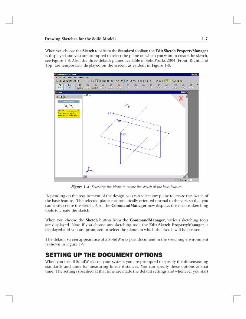
THE SKETCHING ENVIRONMENTWhenever you start a new part document, by default you are in the part modeling environment.However, as mentioned earlier, you need to start the design by first creating the sketch of thebase feature in the sketching environment. You can invoke the sketching environment usingthe Sketch tool available in the Standard toolbar or by using the Sketch tool available in theCommandManager, see Figure 1-7.
Figure 1-7 Different methods of invoking the sketching environment in SolidWorks 2004
Tip. When you open a new SolidWorks document, it is not maximized in theSolidWorks window. This is the reason the area of the new document is not maximum.To maximize the document, choose the Maximize button provided on the upperright corner of the document. You can also maximize the document window bydouble-clicking the blue bar on top of the document window.
Drawing Sketches for the Solid Models 1-7
When you choose the Sketch tool from the Standard toolbar, the Edit Sketch PropertyManageris displayed and you are prompted to select the plane on which you want to create the sketch,see Figure 1-8. Also, the three default planes available in SolidWorks 2004 (Front, Right, andTop) are temporarily displayed on the screen, as evident in Figure 1-8.
Depending on the requirement of the design, you can select any plane to create the sketch ofthe base feature. The selected plane is automatically oriented normal to the view so that youcan easily create the sketch. Also, the CommandManager now displays the various sketchingtools to create the sketch.
When you choose the Sketch button from the CommandManager, various sketching toolsare displayed. Now, if you choose any sketching tool, the Edit Sketch PropertyManager isdisplayed and you are prompted to select the plane on which the sketch will be created.
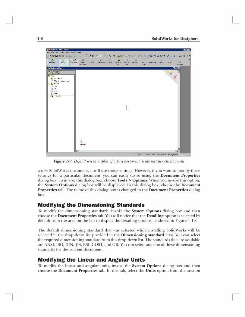
The default screen appearance of a SolidWorks part document in the sketching environmentis shown in Figure 1-9.
SETTING UP THE DOCUMENT OPTIONSWhen you install SolidWorks on your system, you are prompted to specify the dimensioningstandards and units for measuring linear distances. You can specify these options at thattime. The settings specified at that time are made the default settings and whenever you start
Figure 1-8 Selecting the plane to create the sketch of the base feature
1-8 SolidWorks for Designers
a new SolidWorks document, it will use those settings. However, if you want to modify thesesettings for a particular document, you can easily do so using the Document Propertiesdialog box. To invoke this dialog box, choose Tools > Options. When you invoke this option,the System Options dialog box will be displayed. In this dialog box, choose the DocumentProperties tab. The name of this dialog box is changed to the Document Properties dialogbox.
Modifying the Dimensioning StandardsTo modify the dimensioning standards, invoke the System Options dialog box and thenchoose the Document Properties tab. You will notice that the Detailing option is selected bydefault from the area on the left to display the detailing options, as shown in Figure 1-10.
The default dimensioning standard that was selected while installing SolidWorks will beselected in the drop-down list provided in the Dimensioning standard area. You can selectthe required dimensioning standard from this drop-down list. The standards that are availableare ANSI, ISO, DIN, JIS, BSI, GOST, and GB. You can select any one of these dimensioningstandards for the current document.
Modifying the Linear and Angular UnitsTo modify the linear and angular units, invoke the System Options dialog box and thenchoose the Document Properties tab. In this tab, select the Units option from the area on
Figure 1-9 Default screen display of a part document in the sketcher environment

Drawing Sketches for the Solid Models 1-9
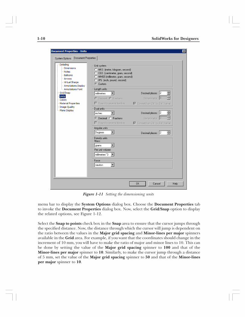
the left to display the options related to linear and angular units, as shown in Figure 1-11.The default option for measuring the linear distances that was selected while installingSolidWorks will be provided in the drop-down list provided in the Length units area. Thevarious types of units that you can select are angstroms, nanometers, microns, millimeters,centimeters, meters, microinches, mils, inches, feet, and feet & inches. You can also changethe units for angular dimensions by selecting it from the drop-down list in the Angular unitsarea. The various types of angular units that can be selected are degrees, deg/min, deg/min/sec,and radians.
Modifying the Snap and Grid SettingsIn the sketching environment of SolidWorks, you can force the cursor to jump through aspecified distance while creating the sketch. Therefore, if you draw a sketch entity, its lengthwill change in the specified increment. For example, you can force the cursor to jump througha distance of 10 mm. As a result, if you are drawing a line, its length will be incrementedthrough a distance of 10 mm while sketching. To do this, choose Tools > Options from the
Figure 1-10 Setting the dimensioning standards
1-10 SolidWorks for Designers
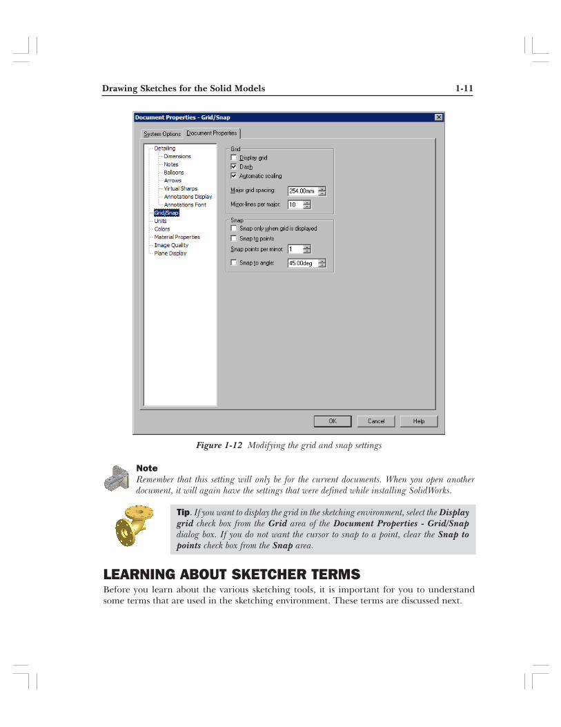
menu bar to display the System Options dialog box. Choose the Document Properties tabto invoke the Document Properties dialog box. Now, select the Grid/Snap option to displaythe related options, see Figure 1-12.
Select the Snap to points check box in the Snap area to ensure that the cursor jumps throughthe specified distance. Now, the distance through which the cursor will jump is dependent onthe ratio between the values in the Major grid spacing and Minor-lines per major spinnersavailable in the Grid area. For example, if you want that the coordinates should change in theincrement of 10 mm, you will have to make the ratio of major and minor lines to 10. This canbe done by setting the value of the Major grid spacing spinner to 100 and that of theMinor-lines per major spinner to 10. Similarly, to make the cursor jump through a distanceof 5 mm, set the value of the Major grid spacing spinner to 50 and that of the Minor-linesper major spinner to 10.
Figure 1-11 Setting the dimensioning units
Drawing Sketches for the Solid Models 1-11
NoteRemember that this setting will only be for the current documents. When you open anotherdocument, it will again have the settings that were defined while installing SolidWorks.
LEARNING ABOUT SKETCHER TERMSBefore you learn about the various sketching tools, it is important for you to understandsome terms that are used in the sketching environment. These terms are discussed next.
Tip. If you want to display the grid in the sketching environment, select the Displaygrid check box from the Grid area of the Document Properties - Grid/Snapdialog box. If you do not want the cursor to snap to a point, clear the Snap topoints check box from the Snap area.
Figure 1-12 Modifying the grid and snap settings
1-12 SolidWorks for Designers
OriginThe origin is a red color icon that is displayed in the center of the sketching environmentscreen. This icon consists of two arrows displaying the X axis and the Y axis direction. Thepoint of intersection of these two axes is the origin point and the coordinates of this point are0,0.
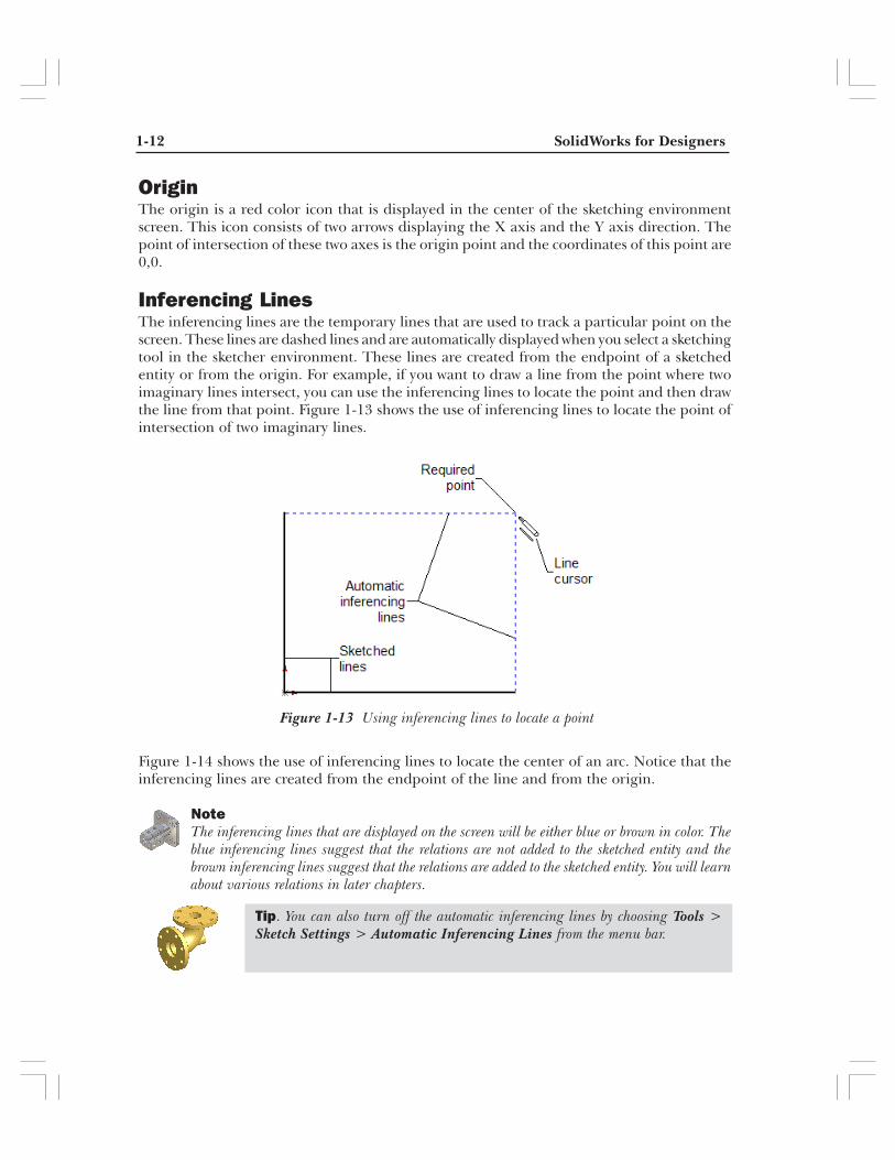
Inferencing LinesThe inferencing lines are the temporary lines that are used to track a particular point on thescreen. These lines are dashed lines and are automatically displayed when you select a sketchingtool in the sketcher environment. These lines are created from the endpoint of a sketchedentity or from the origin. For example, if you want to draw a line from the point where twoimaginary lines intersect, you can use the inferencing lines to locate the point and then drawthe line from that point. Figure 1-13 shows the use of inferencing lines to locate the point ofintersection of two imaginary lines.
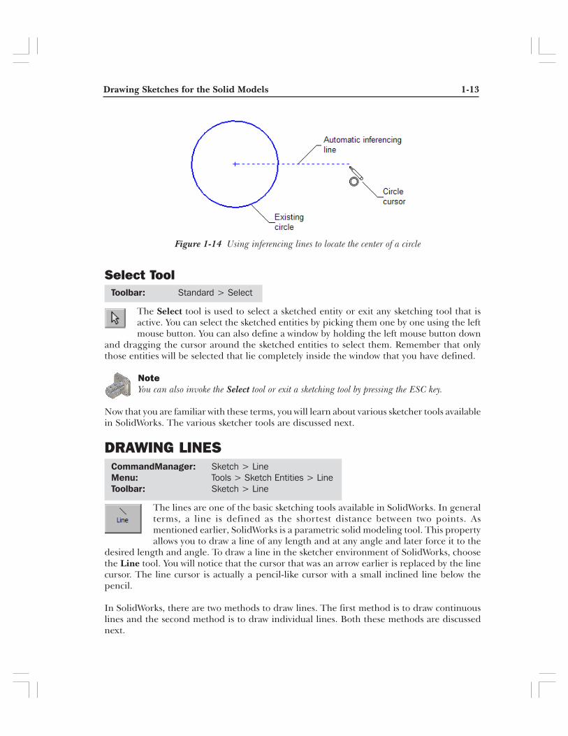
Figure 1-14 shows the use of inferencing lines to locate the center of an arc. Notice that theinferencing lines are created from the endpoint of the line and from the origin.
NoteThe inferencing lines that are displayed on the screen will be either blue or brown in color. Theblue inferencing lines suggest that the relations are not added to the sketched entity and thebrown inferencing lines suggest that the relations are added to the sketched entity. You will learnabout various relations in later chapters.
Figure 1-13 Using inferencing lines to locate a point
Tip. You can also turn off the automatic inferencing lines by choosing Tools >Sketch Settings > Automatic Inferencing Lines from the menu bar.
Drawing Sketches for the Solid Models 1-13
Select Tool
The Select tool is used to select a sketched entity or exit any sketching tool that isactive. You can select the sketched entities by picking them one by one using the leftmouse button. You can also define a window by holding the left mouse button down
and dragging the cursor around the sketched entities to select them. Remember that onlythose entities will be selected that lie completely inside the window that you have defined.
NoteYou can also invoke the Select tool or exit a sketching tool by pressing the ESC key.
Now that you are familiar with these terms, you will learn about various sketcher tools availablein SolidWorks. The various sketcher tools are discussed next.
DRAWING LINES
The lines are one of the basic sketching tools available in SolidWorks. In generalterms, a line is defined as the shortest distance between two points. Asmentioned earlier, SolidWorks is a parametric solid modeling tool. This propertyallows you to draw a line of any length and at any angle and later force it to the
desired length and angle. To draw a line in the sketcher environment of SolidWorks, choosethe Line tool. You will notice that the cursor that was an arrow earlier is replaced by the linecursor. The line cursor is actually a pencil-like cursor with a small inclined line below thepencil.
In SolidWorks, there are two methods to draw lines. The first method is to draw continuouslines and the second method is to draw individual lines. Both these methods are discussednext.
Figure 1-14 Using inferencing lines to locate the center of a circle
Toolbar: Standard > Select
CommandManager: Sketch > LineMenu: Tools > Sketch Entities > LineToolbar: Sketch > Line
1-14 SolidWorks for Designers
Drawing Continuous LinesThis is the default method of drawing lines. In this method you just have to specify the startpoint and the endpoint of the line using the left mouse button. As soon as you specify thestart point of the line, the Line PropertyManager will be displayed on the left of thescreen. However, when you are drawing continuous lines, the options in the LinePropertyManager will not be available. Now, move the cursor away from the start point.
Next, specify the endpoint of the line using the left mouse button. A line will be drawnbetween the two points. You will notice that the line is green in color and has square boxes atthe two ends. The line is displayed in green color because it is still selected. As soon as youdraw another line, choose the Select tool, or choose another tool, the line turns blue in colorand the new line is displayed in green color.
You will notice that after you have drawn the first line, another line is displayed on thescreen. The start point of this line is the endpoint of the last line and the length of this linewill increase or decrease as you move the mouse. This line is called a rubber-band line becausethis line will stretch like a rubber-band as you move the cursor. The point that you specifynext on the screen will be taken as the endpoint of the second line and a line will be drawnsuch that the endpoint of the first line is taken as the start point of the new line and the pointyou specify is taken as the endpoint of the new line. Now, a new rubber-band line is displayedstarting from the endpoint of the last line. This is a continuous process and you can draw asmany continuous lines as you need by specifying the points on the screen using the leftmouse button.
You can exit the continuous line drawing process by pressing the ESC key from the keyboard,by choosing the Select tool, or by double-clicking the screen. You can also right-click todisplay the shortcut menu and choose the End Chain option from the shortcut menu.
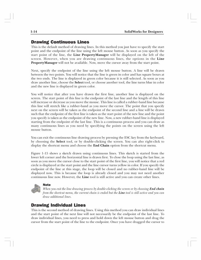
Figure 1-15 shows a sketch drawn using continuous lines. This sketch is started from thelower left corner and the horizontal line is drawn first. To close the loop using the last line, assoon as you move the cursor close to the start point of the first line, you will notice that a redcircle is displayed at the start point and the line cursor turns yellow in color. If you specify theendpoint of the line at this stage, the loop will be closed and no rubber-band line will bedisplayed now. This is because the loop is already closed and you may not need anothercontinuous line now. However, the Line tool is still active and you can create other lines.
NoteWhen you exit the line drawing process by double-clicking the screen or by choosing End chainfrom the shortcut menu, the current chain is ended but the Line tool is still active and you candraw additional lines.
Drawing Individual LinesThis is the second method of drawing lines. Using this method you can draw individual linesand the start point of the next line will not necessarily be the endpoint of the last line. Todraw individual lines, you need to press and hold down the left mouse button and drag thecursor from the start point of the line to the endpoint. Once you have dragged the cursor to
Drawing Sketches for the Solid Models 1-15
the endpoint, release the left mouse button. A line will be drawn between the point fromwhere you started dragging the mouse and the point where you released the mouse.
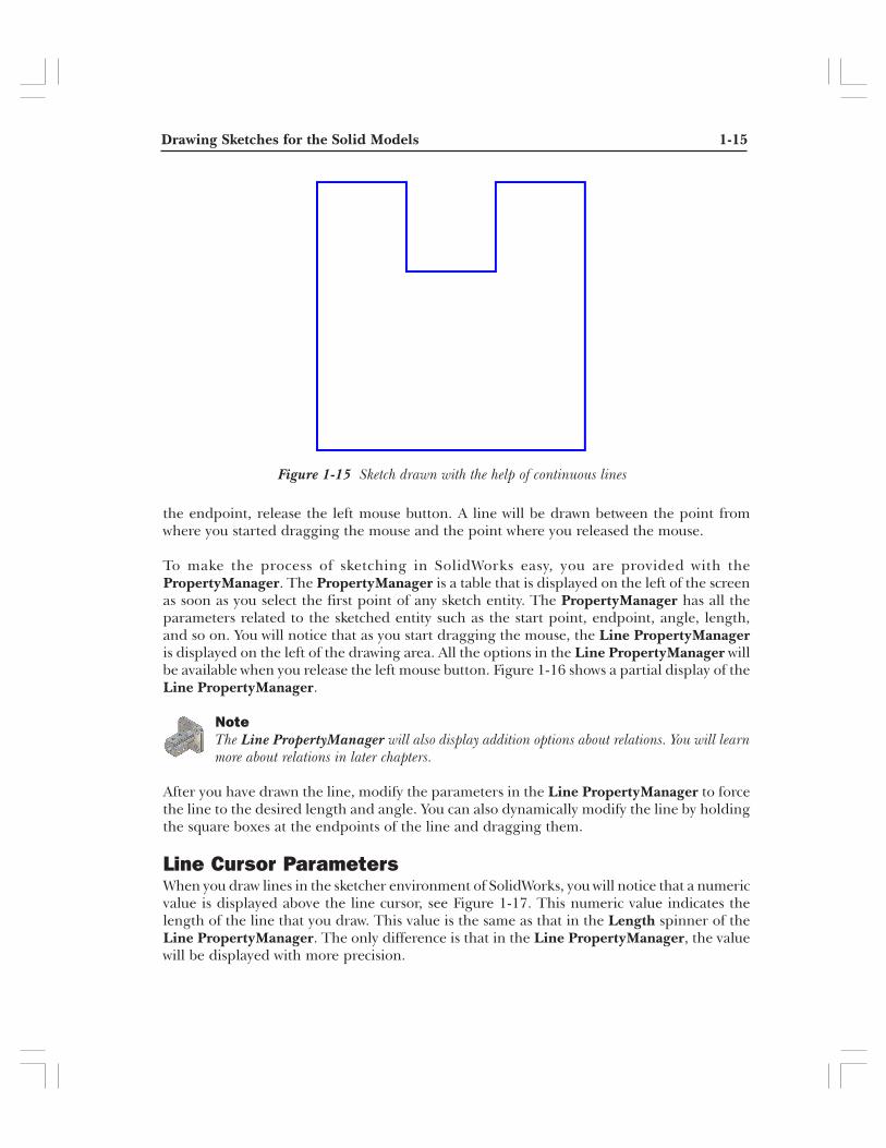
To make the process of sketching in SolidWorks easy, you are provided with thePropertyManager. The PropertyManager is a table that is displayed on the left of the screenas soon as you select the first point of any sketch entity. The PropertyManager has all theparameters related to the sketched entity such as the start point, endpoint, angle, length,and so on. You will notice that as you start dragging the mouse, the Line PropertyManageris displayed on the left of the drawing area. All the options in the Line PropertyManager willbe available when you release the left mouse button. Figure 1-16 shows a partial display of theLine PropertyManager.
NoteThe Line PropertyManager will also display addition options about relations. You will learnmore about relations in later chapters.
After you have drawn the line, modify the parameters in the Line PropertyManager to forcethe line to the desired length and angle. You can also dynamically modify the line by holdingthe square boxes at the endpoints of the line and dragging them.
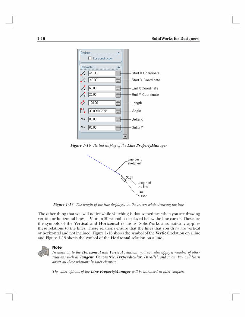
Line Cursor ParametersWhen you draw lines in the sketcher environment of SolidWorks, you will notice that a numericvalue is displayed above the line cursor, see Figure 1-17. This numeric value indicates thelength of the line that you draw. This value is the same as that in the Length spinner of theLine PropertyManager. The only difference is that in the Line PropertyManager, the valuewill be displayed with more precision.
Figure 1-15 Sketch drawn with the help of continuous lines
1-16 SolidWorks for Designers
Figure 1-16 Partial display of the Line PropertyManager
Figure 1-17 The length of the line displayed on the screen while drawing the line
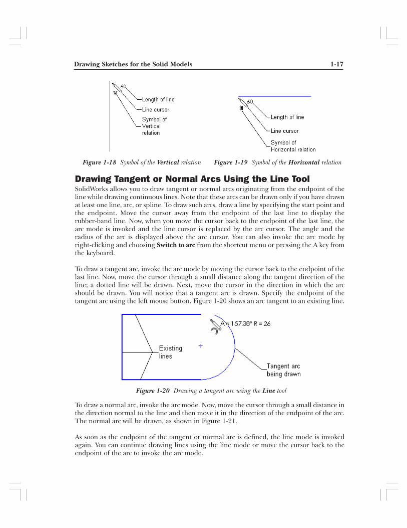
The other thing that you will notice while sketching is that sometimes when you are drawingvertical or horizontal lines, a V or an H symbol is displayed below the line cursor. These arethe symbols of the Vertical and Horizontal relations. SolidWorks automatically appliesthese relations to the lines. These relations ensure that the lines that you draw are verticalor horizontal and not inclined. Figure 1-18 shows the symbol of the Vertical relation on a lineand Figure 1-19 shows the symbol of the Horizontal relation on a line.
NoteIn addition to the Horizontal and Vertical relations, you can also apply a number of otherrelations such as Tangent, Concentric, Perpendicular, Parallel, and so on. You will learnabout all these relations in later chapters.
The other options of the Line PropertyManager will be discussed in later chapters.
Drawing Sketches for the Solid Models 1-17
Drawing Tangent or Normal Arcs Using the Line ToolSolidWorks allows you to draw tangent or normal arcs originating from the endpoint of theline while drawing continuous lines. Note that these arcs can be drawn only if you have drawnat least one line, arc, or spline. To draw such arcs, draw a line by specifying the start point andthe endpoint. Move the cursor away from the endpoint of the last line to display therubber-band line. Now, when you move the cursor back to the endpoint of the last line, thearc mode is invoked and the line cursor is replaced by the arc cursor. The angle and theradius of the arc is displayed above the arc cursor. You can also invoke the arc mode byright-clicking and choosing Switch to arc from the shortcut menu or pressing the A key fromthe keyboard.
To draw a tangent arc, invoke the arc mode by moving the cursor back to the endpoint of thelast line. Now, move the cursor through a small distance along the tangent direction of theline; a dotted line will be drawn. Next, move the cursor in the direction in which the arcshould be drawn. You will notice that a tangent arc is drawn. Specify the endpoint of thetangent arc using the left mouse button. Figure 1-20 shows an arc tangent to an existing line.
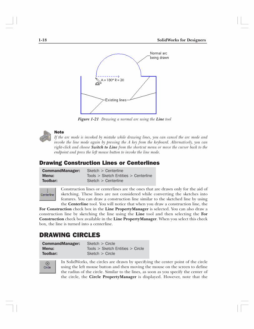
To draw a normal arc, invoke the arc mode. Now, move the cursor through a small distance inthe direction normal to the line and then move it in the direction of the endpoint of the arc.The normal arc will be drawn, as shown in Figure 1-21.
As soon as the endpoint of the tangent or normal arc is defined, the line mode is invokedagain. You can continue drawing lines using the line mode or move the cursor back to theendpoint of the arc to invoke the arc mode.
Figure 1-19 Symbol of the Horizontal relationFigure 1-18 Symbol of the Vertical relation
Figure 1-20 Drawing a tangent arc using the Line tool
1-18 SolidWorks for Designers
CommandManager: Sketch > CircleMenu: Tools > Sketch Entities > CircleToolbar: Sketch > Circle
Figure 1-21 Drawing a normal arc using the Line tool
CommandManager: Sketch > CenterlineMenu: Tools > Sketch Entities > CenterlineToolbar: Sketch > Centerline
NoteIf the arc mode is invoked by mistake while drawing lines, you can cancel the arc mode andinvoke the line mode again by pressing the A key from the keyboard. Alternatively, you canright-click and choose Switch to Line from the shortcut menu or move the cursor back to theendpoint and press the left mouse button to invoke the line mode.
Drawing Construction Lines or Centerlines
Construction lines or centerlines are the ones that are drawn only for the aid ofsketching. These lines are not considered while converting the sketches intofeatures. You can draw a construction line similar to the sketched line by usingthe Centerline tool. You will notice that when you draw a construction line, the
For Construction check box in the Line PropertyManager is selected. You can also draw aconstruction line by sketching the line using the Line tool and then selecting the ForConstruction check box available in the Line PropertyManager. When you select this checkbox, the line is turned into a centerline.
DRAWING CIRCLES
In SolidWorks, the circles are drawn by specifying the center point of the circleusing the left mouse button and then moving the mouse on the screen to definethe radius of the circle. Similar to the lines, as soon as you specify the center ofthe circle, the Circle PropertyManager is displayed. However, note that the
Drawing Sketches for the Solid Models 1-19
options in the Circle PropertyManager will be available only after you have defined theradius of the circle.
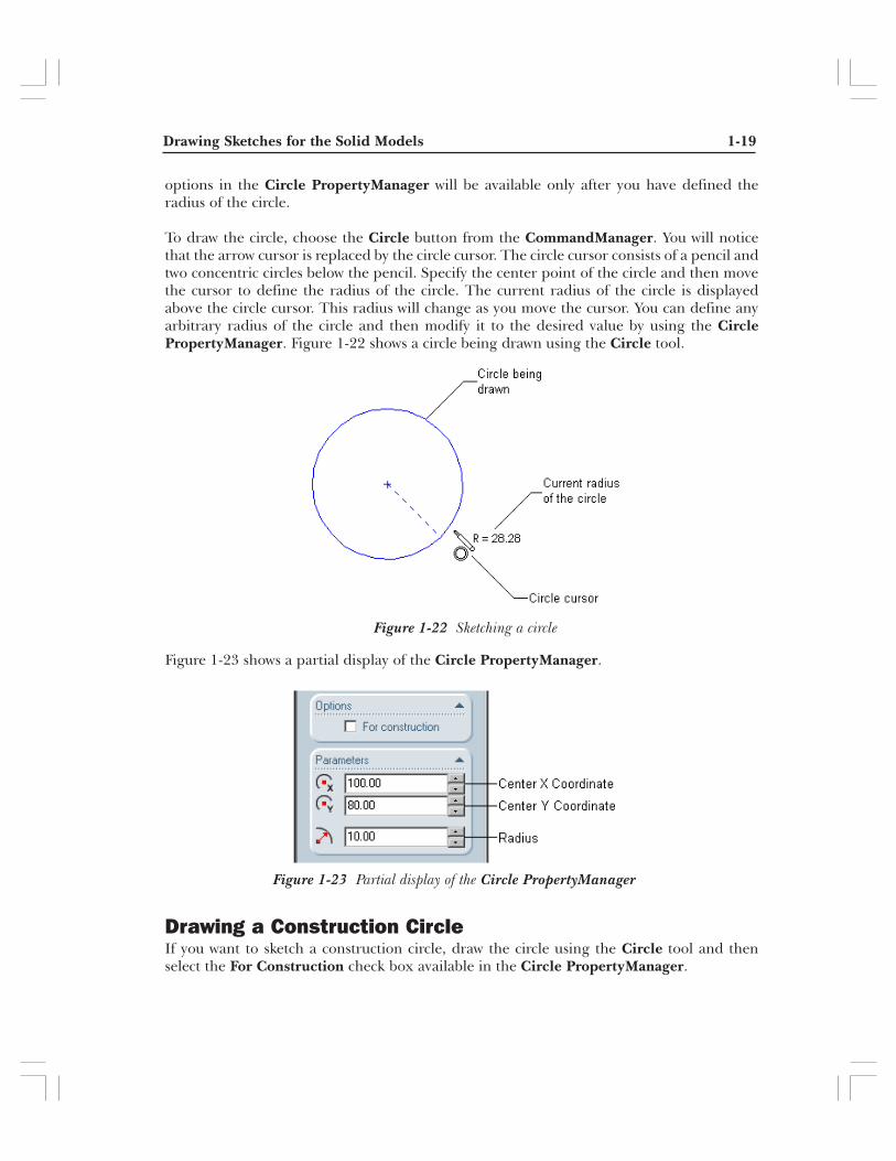
To draw the circle, choose the Circle button from the CommandManager. You will noticethat the arrow cursor is replaced by the circle cursor. The circle cursor consists of a pencil andtwo concentric circles below the pencil. Specify the center point of the circle and then movethe cursor to define the radius of the circle. The current radius of the circle is displayedabove the circle cursor. This radius will change as you move the cursor. You can define anyarbitrary radius of the circle and then modify it to the desired value by using the CirclePropertyManager. Figure 1-22 shows a circle being drawn using the Circle tool.
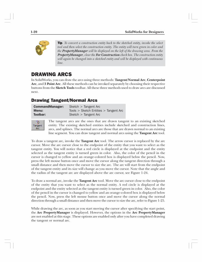
Figure 1-23 shows a partial display of the Circle PropertyManager.
Drawing a Construction CircleIf you want to sketch a construction circle, draw the circle using the Circle tool and thenselect the For Construction check box available in the Circle PropertyManager.
Figure 1-22 Sketching a circle
Figure 1-23 Partial display of the Circle PropertyManager
1-20 SolidWorks for Designers
Tip. To convert a construction entity back to the sketched entity, invoke the selecttool and then select the construction entity. The entity will turn green in color andthe PropertyManager will be displayed on the left of the drawing area. From thePropertyManager, clear the For Construction check box. The construction entitywill again be changed into a sketched entity and will be displayed with continuousline.
DRAWING ARCSIn SolidWorks, you can draw the arcs using three methods: Tangent/Normal Arc, CenterpointArc, and 3 Point Arc. All these methods can be invoked separately by choosing their respectivebuttons from the Sketch Tools toolbar. All these three methods used to draw arcs are discussednext.
Drawing Tangent/Normal Arcs
The tangent arcs are the ones that are drawn tangent to an existing sketchedentity. The existing sketched entities include sketched and construction lines,arcs, and splines. The normal arcs are those that are drawn normal to an existingline segment. You can draw tangent and normal arcs using the Tangent Arc tool.
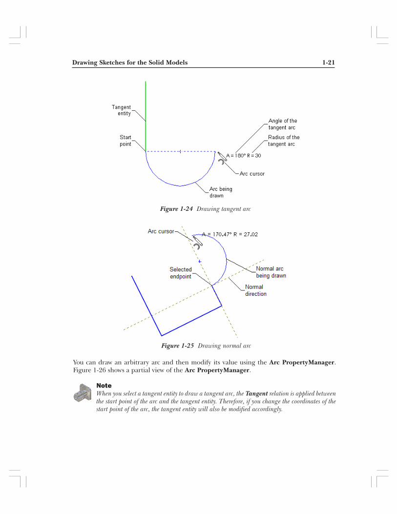
To draw a tangent arc, invoke the Tangent Arc tool. The arrow cursor is replaced by the arccursor. Move the arc cursor close to the endpoint of the entity that you want to select as thetangent entity. You will notice that a red circle is displayed at the endpoint and the entityselected as the tangent entity is turned green in color. Also, the color of the pencil in thecursor is changed to yellow and an orange-colored box is displayed below the pencil. Now,press the left mouse button once and move the cursor along the tangent direction through asmall distance and then move the cursor to size the arc. The arc will start from the endpointof the tangent entity and its size will change as you move the cursor. Note that the angle andthe radius of the tangent arc are displayed above the arc cursor, see Figure 1-24.
To draw a normal arc, invoke the Tangent Arc tool. Move the arc cursor close to the endpointof the entity that you want to select as the normal entity. A red circle is displayed at theendpoint and the entity selected as the tangent entity is turned green in color. Also, the colorof the pencil in the cursor is changed to yellow and an orange-colored box is displayed belowthe pencil. Now, press the left mouse button once and move the cursor along the normaldirection through a small distance and then move the cursor to size the arc, refer to Figure 1-25.
While drawing the arc, as soon as you start moving the cursor after specifying the start point,the Arc PropertyManager is displayed. However, the options in the Arc PropertyManagerare not enabled at this stage. These options are enabled only after you have completed drawingthe tangent or normal arc.
CommandManager: Sketch > Tangent ArcMenu: Tools > Sketch Entities > Tangent ArcToolbar: Sketch > Tangent Arc
Drawing Sketches for the Solid Models 1-21
Figure 1-24 Drawing tangent arc
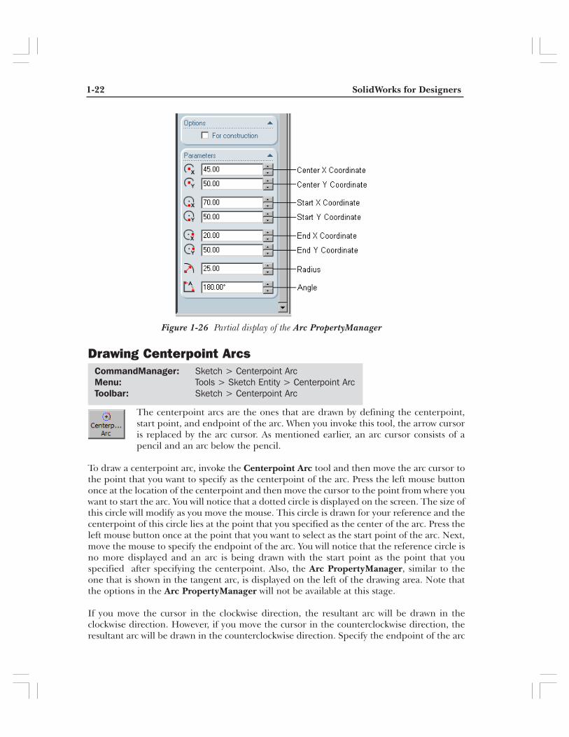
You can draw an arbitrary arc and then modify its value using the Arc PropertyManager.Figure 1-26 shows a partial view of the Arc PropertyManager.
NoteWhen you select a tangent entity to draw a tangent arc, the Tangent relation is applied betweenthe start point of the arc and the tangent entity. Therefore, if you change the coordinates of thestart point of the arc, the tangent entity will also be modified accordingly.
Figure 1-25 Drawing normal arc
1-22 SolidWorks for Designers
CommandManager: Sketch > Centerpoint ArcMenu: Tools > Sketch Entity > Centerpoint ArcToolbar: Sketch > Centerpoint Arc
Drawing Centerpoint Arcs
The centerpoint arcs are the ones that are drawn by defining the centerpoint,start point, and endpoint of the arc. When you invoke this tool, the arrow cursoris replaced by the arc cursor. As mentioned earlier, an arc cursor consists of apencil and an arc below the pencil.
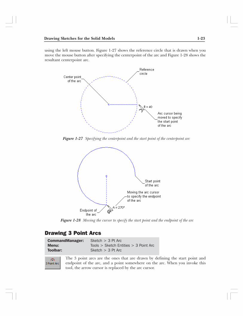
To draw a centerpoint arc, invoke the Centerpoint Arc tool and then move the arc cursor tothe point that you want to specify as the centerpoint of the arc. Press the left mouse buttononce at the location of the centerpoint and then move the cursor to the point from where youwant to start the arc. You will notice that a dotted circle is displayed on the screen. The size ofthis circle will modify as you move the mouse. This circle is drawn for your reference and thecenterpoint of this circle lies at the point that you specified as the center of the arc. Press theleft mouse button once at the point that you want to select as the start point of the arc. Next,move the mouse to specify the endpoint of the arc. You will notice that the reference circle isno more displayed and an arc is being drawn with the start point as the point that youspecified after specifying the centerpoint. Also, the Arc PropertyManager, similar to theone that is shown in the tangent arc, is displayed on the left of the drawing area. Note thatthe options in the Arc PropertyManager will not be available at this stage.
If you move the cursor in the clockwise direction, the resultant arc will be drawn in theclockwise direction. However, if you move the cursor in the counterclockwise direction, theresultant arc will be drawn in the counterclockwise direction. Specify the endpoint of the arc
Figure 1-26 Partial display of the Arc PropertyManager
Drawing Sketches for the Solid Models 1-23
Figure 1-28 Moving the cursor to specify the start point and the endpoint of the arc
Figure 1-27 Specifying the centerpoint and the start point of the centerpoint arc
using the left mouse button. Figure 1-27 shows the reference circle that is drawn when youmove the mouse button after specifying the centerpoint of the arc and Figure 1-28 shows theresultant centerpoint arc.
Drawing 3 Point Arcs
The 3 point arcs are the ones that are drawn by defining the start point andendpoint of the arc, and a point somewhere on the arc. When you invoke thistool, the arrow cursor is replaced by the arc cursor.
CommandManager: Sketch > 3 Pt ArcMenu: Tools > Sketch Entities > 3 Point ArcToolbar: Sketch > 3 Pt Arc

1-24 SolidWorks for Designers
Figure 1-29 Specifying the start point and the endpoint of the arc
Figure 1-30 Specifying a point on the arc to draw it
To draw a 3 point arc, invoke the 3 Pt Arc tool and then move the arc cursor to the point thatyou want to specify as the start point of the arc. Press the left mouse button once at thelocation of the start point and then move the cursor to the point that you want specify as theendpoint of the arc. As soon as you start moving the cursor after specifying the start point, areference arc will be drawn and the Arc PropertyManager will be displayed. However, theoptions in the Arc PropertyManager will not be available at this stage.
Using the left mouse button, specify the endpoint of the arc. You will notice that the referencearc is no more displayed. Instead, a solid arc is displayed and the cursor is attached to the arc.As you move the cursor, the arc will also be modified dynamically. Using the left mousebutton, specify a point on the screen to create the arc. The last point that you specify willdetermine the direction of the arc. The options in the Arc PropertyManager will be displayedafter you have drawn the arc. You can modify the properties of the arc using the ArcPropertyManager. Figure 1-29 shows the reference arc that is drawn by specifying thestart point and the endpoint of the arc and Figure 1-30 shows the resultant 3 point arc.
Drawing Sketches for the Solid Models 1-25
Figure 1-31 Drawing a rectangle by specifying two opposite corners
DRAWING RECTANGLES
In SolidWorks, the rectangles are drawn by specifying two opposite corners ofthe rectangle. To draw a rectangle, invoke the Rectangle tool. The arrow cursorwill be replaced by the rectangle cursor. Move the cursor to the point that youwant to specify as the first corner of the rectangle. Press the left mouse button
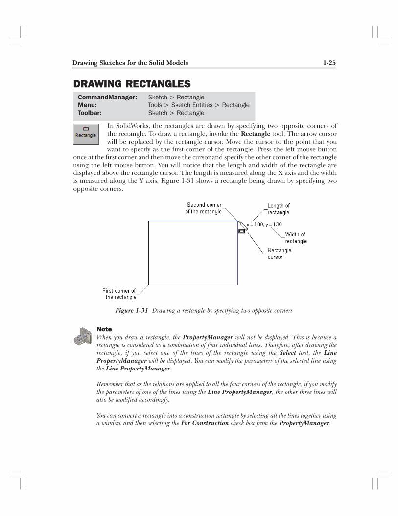
once at the first corner and then move the cursor and specify the other corner of the rectangleusing the left mouse button. You will notice that the length and width of the rectangle aredisplayed above the rectangle cursor. The length is measured along the X axis and the widthis measured along the Y axis. Figure 1-31 shows a rectangle being drawn by specifying twoopposite corners.
NoteWhen you draw a rectangle, the PropertyManager will not be displayed. This is because arectangle is considered as a combination of four individual lines. Therefore, after drawing therectangle, if you select one of the lines of the rectangle using the Select tool, the LinePropertyManager will be displayed. You can modify the parameters of the selected line usingthe Line PropertyManager.
Remember that as the relations are applied to all the four corners of the rectangle, if you modifythe parameters of one of the lines using the Line PropertyManager, the other three lines willalso be modified accordingly.
You can convert a rectangle into a construction rectangle by selecting all the lines together usinga window and then selecting the For Construction check box from the PropertyManager.
CommandManager: Sketch > RectangleMenu: Tools > Sketch Entities > RectangleToolbar: Sketch > Rectangle
1-26 SolidWorks for Designers
Figure 1-32 Rectangle at an angle
DRAWING PARALLELOGRAM
In SolidWorks, the Parallelogram tool can be used to draw a parallelogram and also to drawa rectangle at an angle. The methods used to draw both these entities are discussed next.
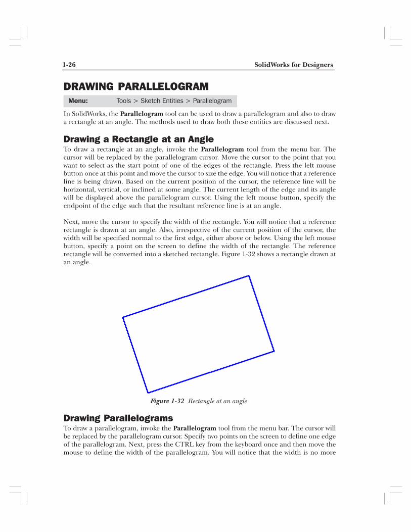
Drawing a Rectangle at an AngleTo draw a rectangle at an angle, invoke the Parallelogram tool from the menu bar. Thecursor will be replaced by the parallelogram cursor. Move the cursor to the point that youwant to select as the start point of one of the edges of the rectangle. Press the left mousebutton once at this point and move the cursor to size the edge. You will notice that a referenceline is being drawn. Based on the current position of the cursor, the reference line will behorizontal, vertical, or inclined at some angle. The current length of the edge and its anglewill be displayed above the parallelogram cursor. Using the left mouse button, specify theendpoint of the edge such that the resultant reference line is at an angle.
Next, move the cursor to specify the width of the rectangle. You will notice that a referencerectangle is drawn at an angle. Also, irrespective of the current position of the cursor, thewidth will be specified normal to the first edge, either above or below. Using the left mousebutton, specify a point on the screen to define the width of the rectangle. The referencerectangle will be converted into a sketched rectangle. Figure 1-32 shows a rectangle drawn atan angle.
Drawing ParallelogramsTo draw a parallelogram, invoke the Parallelogram tool from the menu bar. The cursor willbe replaced by the parallelogram cursor. Specify two points on the screen to define one edgeof the parallelogram. Next, press the CTRL key from the keyboard once and then move themouse to define the width of the parallelogram. You will notice that the width is no more
Menu: Tools > Sketch Entities > Parallelogram
Drawing Sketches for the Solid Models 1-27
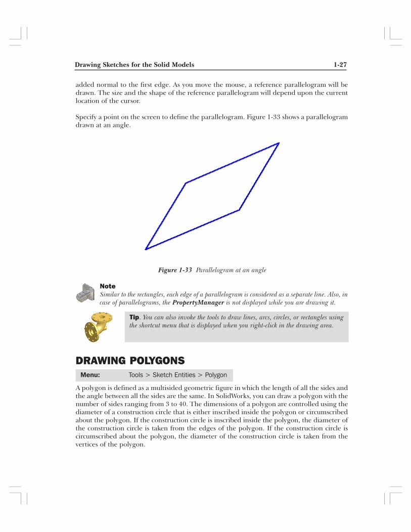
added normal to the first edge. As you move the mouse, a reference parallelogram will bedrawn. The size and the shape of the reference parallelogram will depend upon the currentlocation of the cursor.
Specify a point on the screen to define the parallelogram. Figure 1-33 shows a parallelogramdrawn at an angle.
NoteSimilar to the rectangles, each edge of a parallelogram is considered as a separate line. Also, incase of parallelograms, the PropertyManager is not displayed while you are drawing it.
DRAWING POLYGONS
A polygon is defined as a multisided geometric figure in which the length of all the sides andthe angle between all the sides are the same. In SolidWorks, you can draw a polygon with thenumber of sides ranging from 3 to 40. The dimensions of a polygon are controlled using thediameter of a construction circle that is either inscribed inside the polygon or circumscribedabout the polygon. If the construction circle is inscribed inside the polygon, the diameter ofthe construction circle is taken from the edges of the polygon. If the construction circle iscircumscribed about the polygon, the diameter of the construction circle is taken from thevertices of the polygon.
Menu: Tools > Sketch Entities > Polygon
Figure 1-33 Parallelogram at an angle
Tip. You can also invoke the tools to draw lines, arcs, circles, or rectangles usingthe shortcut menu that is displayed when you right-click in the drawing area.
1-28 SolidWorks for Designers
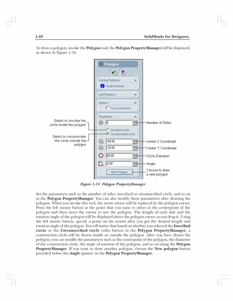
Figure 1-34 Polygon PropertyManager
To draw a polygon, invoke the Polygon tool; the Polygon PropertyManager will be displayed,as shown in Figure 1-34.
Set the parameters such as the number of sides, inscribed or circumscribed circle, and so onin the Polygon PropertyManager. You can also modify these parameters after drawing thepolygon. When you invoke this tool, the arrow cursor will be replaced by the polygon cursor.Press the left mouse button at the point that you want to select as the centerpoint of thepolygon and then move the cursor to size the polygon. The length of each side and therotation angle of the polygon will be displayed above the polygon cursor as you drag it. Usingthe left mouse button, specify a point on the screen after you get the desired length androtation angle of the polygon. You will notice that based on whether you selected the Inscribedcircle or the Circumscribed circle radio button in the Polygon PropertyManager, aconstruction circle will be drawn inside or outside the polygon. After you have drawn thepolygon, you can modify the parameters such as the centerpoint of the polygon, the diameterof the construction circle, the angle of rotation of the polygon, and so on using the PolygonPropertyManager. If you want to draw another polygon, choose the New polygon buttonprovided below the Angle spinner in the Polygon PropertyManager.

Drawing Sketches for the Solid Models 1-29
Figure 1-35 Six-sided polygon with construction circle inscribed inside the polygon
Figure 1-35 shows a six-sided polygon with the construction circle inscribed inside the polygonand Figure 1-36 shows a five-sided polygon with the construction circle circumscribed outsidethe polygon. Notice that the reference circle is retained with the polygon. Remember thatthis circle will not be considered while converting the polygon into a feature.
DRAWING SPLINES
Figure 1-36 Five-sided polygon with construction circle circumscribed outside the polygon
CommandManager: Sketch > SplineMenu: Tools > Sketch Entities > SplineToolbar: Sketch > Spline
1-30 SolidWorks for Designers
Figure 1-37 Sketched spline with start point at the origin
Tip. After creating the spline, when you select it using the Select tool, the SplinePropertyManager is displayed. The current handle will be displayed with a filledsquare and its number and the corresponding X and Y coordinates will be displayedin the Spline PropertyManager. You can modify these coordinates to modify theselected spline.
CommandManager: Sketch > PointMenu: Tools > Sketch Entities > PointToolbar: Sketch > Point
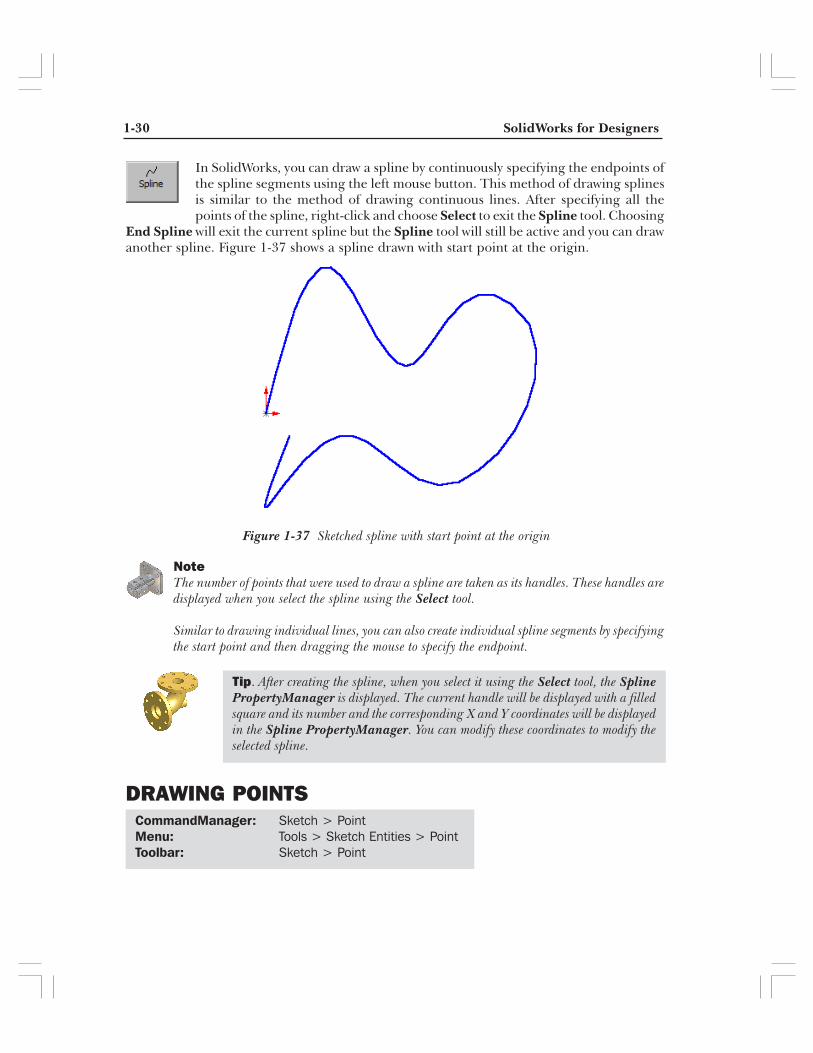
In SolidWorks, you can draw a spline by continuously specifying the endpoints ofthe spline segments using the left mouse button. This method of drawing splinesis similar to the method of drawing continuous lines. After specifying all thepoints of the spline, right-click and choose Select to exit the Spline tool. Choosing
End Spline will exit the current spline but the Spline tool will still be active and you can drawanother spline. Figure 1-37 shows a spline drawn with start point at the origin.
NoteThe number of points that were used to draw a spline are taken as its handles. These handles aredisplayed when you select the spline using the Select tool.
Similar to drawing individual lines, you can also create individual spline segments by specifyingthe start point and then dragging the mouse to specify the endpoint.
DRAWING POINTS
Drawing Sketches for the Solid Models 1-31
To draw a point, choose the Point tool from the CommandManager and thenspecify the point on the screen where you want to place the point. The PointPropertyManager will be displayed with the X and Y coordinates of the currentpoint. You can modify the location of the point by modifying its X and Y
coordinates in the Point PropertyManager.
DRAWING ELLIPSES
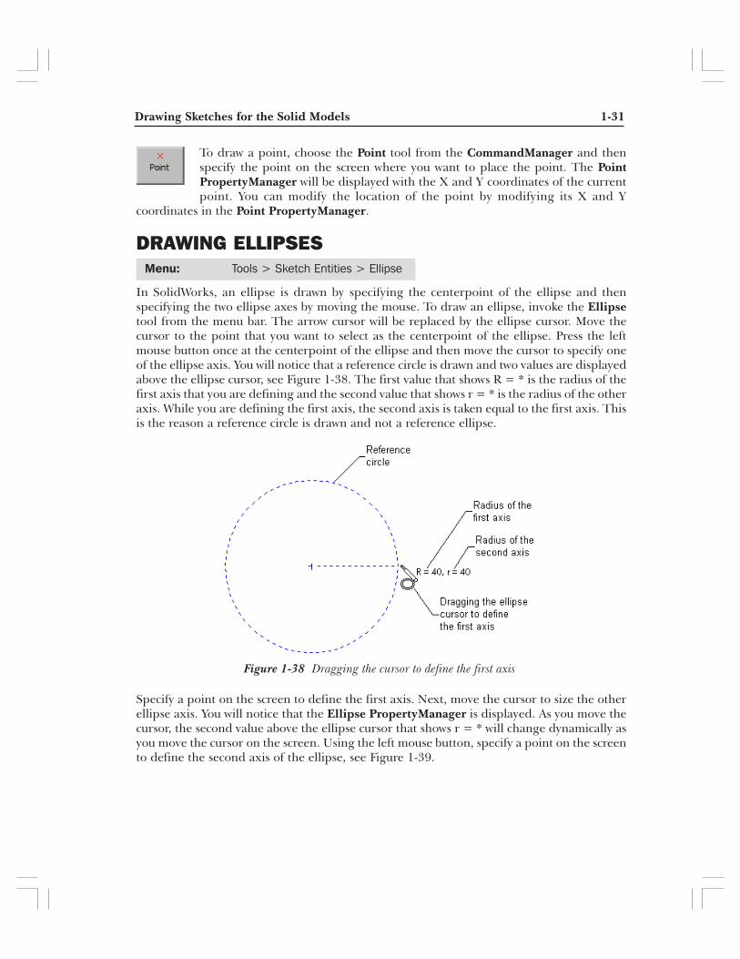
In SolidWorks, an ellipse is drawn by specifying the centerpoint of the ellipse and thenspecifying the two ellipse axes by moving the mouse. To draw an ellipse, invoke the Ellipsetool from the menu bar. The arrow cursor will be replaced by the ellipse cursor. Move thecursor to the point that you want to select as the centerpoint of the ellipse. Press the leftmouse button once at the centerpoint of the ellipse and then move the cursor to specify oneof the ellipse axis. You will notice that a reference circle is drawn and two values are displayedabove the ellipse cursor, see Figure 1-38. The first value that shows R = * is the radius of thefirst axis that you are defining and the second value that shows r = * is the radius of the otheraxis. While you are defining the first axis, the second axis is taken equal to the first axis. Thisis the reason a reference circle is drawn and not a reference ellipse.
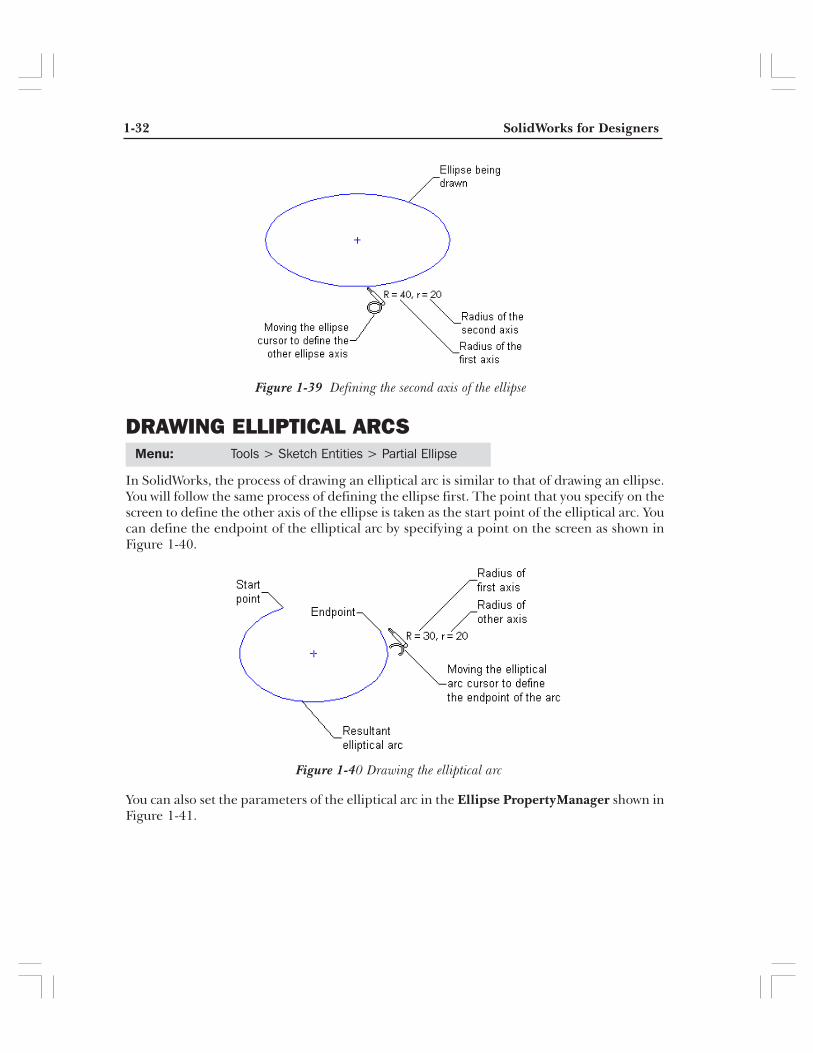
Specify a point on the screen to define the first axis. Next, move the cursor to size the otherellipse axis. You will notice that the Ellipse PropertyManager is displayed. As you move thecursor, the second value above the ellipse cursor that shows r = * will change dynamically asyou move the cursor on the screen. Using the left mouse button, specify a point on the screento define the second axis of the ellipse, see Figure 1-39.
Menu: Tools > Sketch Entities > Ellipse
Figure 1-38 Dragging the cursor to define the first axis
1-32 SolidWorks for Designers
Menu: Tools > Sketch Entities > Partial Ellipse
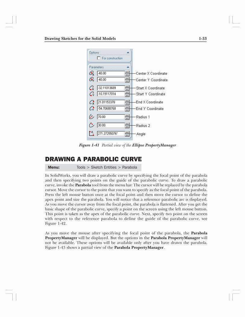
Figure 1-40 Drawing the elliptical arc
DRAWING ELLIPTICAL ARCS
In SolidWorks, the process of drawing an elliptical arc is similar to that of drawing an ellipse.You will follow the same process of defining the ellipse first. The point that you specify on thescreen to define the other axis of the ellipse is taken as the start point of the elliptical arc. Youcan define the endpoint of the elliptical arc by specifying a point on the screen as shown inFigure 1-40.
You can also set the parameters of the elliptical arc in the Ellipse PropertyManager shown inFigure 1-41.
Figure 1-39 Defining the second axis of the ellipse
Drawing Sketches for the Solid Models 1-33
DRAWING A PARABOLIC CURVE
In SolidWorks, you will draw a parabolic curve by specifying the focal point of the parabolaand then specifying two points on the guide of the parabolic curve. To draw a paraboliccurve, invoke the Parabola tool from the menu bar. The cursor will be replaced by the parabolacursor. Move the cursor to the point that you want to specify as the focal point of the parabola.Press the left mouse button once at the focal point and then move the cursor to define theapex point and size the parabola. You will notice that a reference parabolic arc is displayed.As you move the cursor away from the focal point, the parabola is flattened. After you get thebasic shape of the parabolic curve, specify a point on the screen using the left mouse button.This point is taken as the apex of the parabolic curve. Next, specify two point on the screenwith respect to the reference parabola to define the guide of the parabolic curve, seeFigure 1-42.
As you move the mouse after specifying the focal point of the parabola, the ParabolaPropertyManager will be displayed. But the options in the Parabola PropertyManager willnot be available. These options will be available only after you have drawn the parabola.Figure 1-43 shows a partial view of the Parabola PropertyManager.
Menu: Tools > Sketch Entities > Parabola
Figure 1-41 Partial view of the Ellipse PropertyManager

1-34 SolidWorks for Designers
DRAWING DISPLAY TOOLSThe drawing display tools are one of the most important tools provided in any of the solidmodeling software. These tools allow you to modify the display of the drawing by zooming orpanning the drawing. Some of the drawing display tools that are available in SolidWorks arediscussed in this chapter. The remaining tools are discussed in the later chapters.
Figure 1-42 Drawing the parabola
Figure 1-43 Partial view of the Parabola Proper-tyManager
Drawing Sketches for the Solid Models 1-35
Zoom to Fit
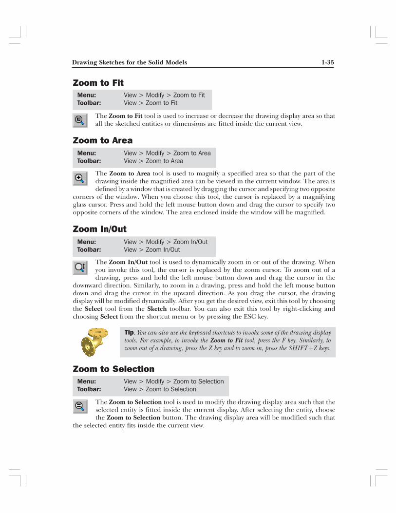
The Zoom to Fit tool is used to increase or decrease the drawing display area so thatall the sketched entities or dimensions are fitted inside the current view.
Zoom to Area
The Zoom to Area tool is used to magnify a specified area so that the part of thedrawing inside the magnified area can be viewed in the current window. The area isdefined by a window that is created by dragging the cursor and specifying two opposite
corners of the window. When you choose this tool, the cursor is replaced by a magnifyingglass cursor. Press and hold the left mouse button down and drag the cursor to specify twoopposite corners of the window. The area enclosed inside the window will be magnified.
Zoom In/Out
The Zoom In/Out tool is used to dynamically zoom in or out of the drawing. Whenyou invoke this tool, the cursor is replaced by the zoom cursor. To zoom out of adrawing, press and hold the left mouse button down and drag the cursor in the
downward direction. Similarly, to zoom in a drawing, press and hold the left mouse buttondown and drag the cursor in the upward direction. As you drag the cursor, the drawingdisplay will be modified dynamically. After you get the desired view, exit this tool by choosingthe Select tool from the Sketch toolbar. You can also exit this tool by right-clicking andchoosing Select from the shortcut menu or by pressing the ESC key.
Zoom to Selection
The Zoom to Selection tool is used to modify the drawing display area such that theselected entity is fitted inside the current display. After selecting the entity, choosethe Zoom to Selection button. The drawing display area will be modified such that
the selected entity fits inside the current view.
Menu: View > Modify > Zoom to FitToolbar: View > Zoom to Fit
Menu: View > Modify > Zoom to AreaToolbar: View > Zoom to Area
Menu: View > Modify > Zoom In/OutToolbar: View > Zoom In/Out
Menu: View > Modify > Zoom to SelectionToolbar: View > Zoom to Selection
Tip. You can also use the keyboard shortcuts to invoke some of the drawing displaytools. For example, to invoke the Zoom to Fit tool, press the F key. Similarly, tozoom out of a drawing, press the Z key and to zoom in, press the SHIFT+Z keys.
1-36 SolidWorks for Designers
Pan
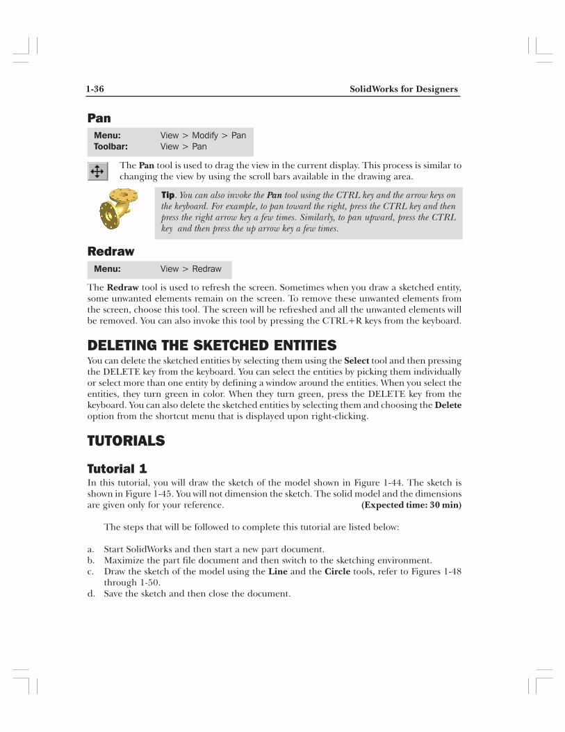
The Pan tool is used to drag the view in the current display. This process is similar tochanging the view by using the scroll bars available in the drawing area.
Redraw
The Redraw tool is used to refresh the screen. Sometimes when you draw a sketched entity,some unwanted elements remain on the screen. To remove these unwanted elements fromthe screen, choose this tool. The screen will be refreshed and all the unwanted elements willbe removed. You can also invoke this tool by pressing the CTRL+R keys from the keyboard.
DELETING THE SKETCHED ENTITIESYou can delete the sketched entities by selecting them using the Select tool and then pressingthe DELETE key from the keyboard. You can select the entities by picking them individuallyor select more than one entity by defining a window around the entities. When you select theentities, they turn green in color. When they turn green, press the DELETE key from thekeyboard. You can also delete the sketched entities by selecting them and choosing the Deleteoption from the shortcut menu that is displayed upon right-clicking.
TUTORIALS
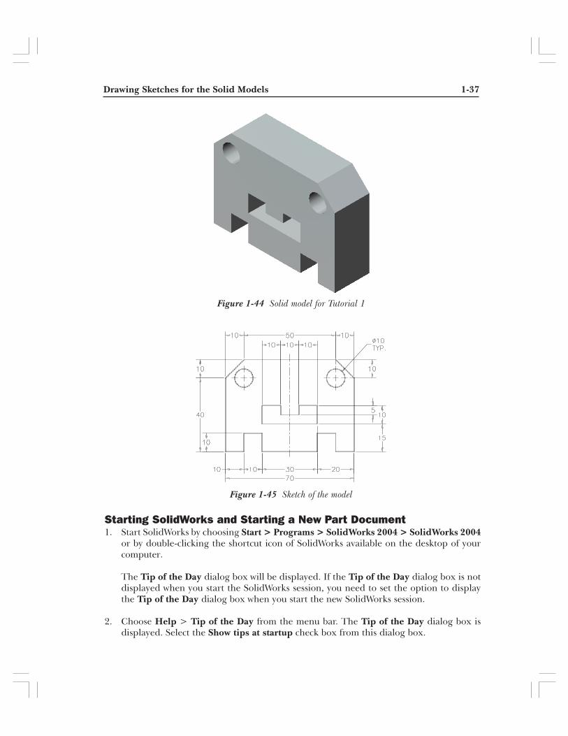
Tutorial 1In this tutorial, you will draw the sketch of the model shown in Figure 1-44. The sketch isshown in Figure 1-45. You will not dimension the sketch. The solid model and the dimensionsare given only for your reference. (Expected time: 30 min)
The steps that will be followed to complete this tutorial are listed below:
a. Start SolidWorks and then start a new part document.b. Maximize the part file document and then switch to the sketching environment.c. Draw the sketch of the model using the Line and the Circle tools, refer to Figures 1-48
through 1-50.d. Save the sketch and then close the document.
Menu: View > Modify > PanToolbar: View > Pan
Menu: View > Redraw
Tip. You can also invoke the Pan tool using the CTRL key and the arrow keys onthe keyboard. For example, to pan toward the right, press the CTRL key and thenpress the right arrow key a few times. Similarly, to pan upward, press the CTRLkey and then press the up arrow key a few times.
Drawing Sketches for the Solid Models 1-37
Starting SolidWorks and Starting a New Part Document1. Start SolidWorks by choosing Start > Programs > SolidWorks 2004 > SolidWorks 2004
or by double-clicking the shortcut icon of SolidWorks available on the desktop of yourcomputer.
The Tip of the Day dialog box will be displayed. If the Tip of the Day dialog box is notdisplayed when you start the SolidWorks session, you need to set the option to displaythe Tip of the Day dialog box when you start the new SolidWorks session.
2. Choose Help > Tip of the Day from the menu bar. The Tip of the Day dialog box isdisplayed. Select the Show tips at startup check box from this dialog box.
Figure 1-44 Solid model for Tutorial 1
Figure 1-45 Sketch of the model

1-38 SolidWorks for Designers
Figure 1-46 New SolidWorks Document dialog box
By selecting the Show tips at startup check box, the Tip of the Day dialog box will bedisplayed every time you start the SolidWorks session. You can get many valuable tipsfrom the Tip of the Day dialog box. The tips displayed in this dialog box are helpful tomake the full utilization of this CAD package.
3. Close the Tip of the Day dialog box by choosing the Close button. The Welcome toSolidWorks 2004 window is displayed. Choose the New Document option from thiswindow.
The New SolidWorks Document dialog box is displayed.
4. The Part button is chosen by default. Choose the OK button from the NewSolidWorks Document dialog box as shown in Figure 1-46.
A new SolidWorks part document will be opened. But the part document window will notbe maximized in the SolidWorks window.
Tip. If the shortcut icon of SolidWorks is not created automatically on the desktopof your system when you install SolidWorks, you can create it manually. To createthe shortcut icon on the desktop, choose Start > Programs > SolidWorks 2004to display the SolidWorks cascading menu. Right-click SolidWorks 2004 in thecascading menu and then choose Send To > Desktop (create shortcut) from theshortcut menu.

Drawing Sketches for the Solid Models 1-39
5. Choose the Maximize button available on the upper right corner of the part documentwindow to maximize the document window.
When you open a new part document, the part modeling environment is active by default.As you first need to draw the sketch of the feature, you need to invoke the sketchingenvironment.
6. Choose the Sketch button from the Standard toolbar. The Edit SketchPropertyManager is displayed and you are prompted to select a plane on whichyou want to create the sketch.
7. Select the Front plane. The sketching environment is invoked and the plane is orientednormal to the view. You will notice that a red color origin is displayed in the center of thescreen, indicating the sketching environment. The default screen appearance of thesketching environment of SolidWorks is shown in Figure 1-47.
Figure 1-47 Screen display in the sketcher environment
Tip. If the grid is displayed on the screen when you invoke the sketching environmentfor the first time, then you can set the option to turn off the grid display. Right-clickin the drawing area to display the shortcut menu. The Display Grid option has acheck mark on its left, suggesting that this option is chosen. Select this option againto turn the grids off.

1-40 SolidWorks for Designers
Setting the Units and GridIt is assumed that while installing SolidWorks, you selected the option of measuring thelength in millimeters. This is the reason the length will be measured in millimeter in thecurrent file. But if you selected some other unit, you need to make some initial settings ofchanging the linear and angular units before you proceed with drawing the sketch.
1. Choose Tools > Options from the menu bar to invoke the System Options - Generaldialog box.
2. Choose the Document Properties tab. The name of the dialog box is changed to theDocument Properties - Detailing dialog box.
3. Select the Units option from the area on the left to display the options related to linearand angular units.
4. Select millimeters from the drop-down list available in the Length units area. Also,select the Degrees option from the drop-down list provided in the Angular units area.
NoteIf you selected Millimeters as the unit while installing SolidWorks, you can skip the pointsdiscussed earlier in this section.
5. Select Grid/Snap from the area on the left. Set the value of the Major grid spacingspinner to 100 and the value of the Minor-lines per major spinner to 10.
6. Select the Snap to points check box in the Snap area, if it is cleared. Choose OK to exitthe dialog box.
Drawing the Outer Loop of the SketchIt is a good practice to draw the sketch on one side of the origin, preferably in the firstquadrant. This is because while generating the part program for manufacturing the part,you will have a reference for work origin in advance.
The sketch of the model consists of an outer loop, two circles inside the outer loop, anda cavity. Therefore, it will be drawn using the Line and the Circle tools. You will firstdraw the outer loop and then the inner entities. Note that in the sketcher environment,the lower right corner of the SolidWorks window displays three areas. The first areadisplays the X, Y, and Z coordinates of the current location of the cursor. These coordinateswill be modified as you move the cursor around the drawing area. You will use thecoordinate display to draw the sketch of the model.
You will start drawing the sketch from the lower left corner of the sketch and the outerloop will be drawn using the continuous lines.
1. Choose the Line button from the Sketch CommandManager to invoke theLine tool. The arrow cursor will be replaced by the line cursor.

Drawing Sketches for the Solid Models 1-41
2. Move the cursor in the first quadrant close to the origin. The coordinates of the point aredisplayed close to the lower right corner of the screen.
3. Press the left mouse button at the point whose coordinates are 10 mm 10 mm 0 mm andthen move the cursor horizontally toward the right.
You will notice that the symbol of Horizontal relation is displayed below the line cursorand the length of the line is displayed above the line cursor.
As the length of the first horizontal line at the lower left corner is 10 mm, you will movethe mouse until the length of the line is shown as 10 above the line cursor.
4. Press the left mouse button when the length of the line that is displayed above the linecursor shows a value of 10.
The first horizontal line is drawn. Because you are drawing continuous lines, the endpointof the last line is automatically selected as the start point of the next line.
5. Move the line cursor vertically upward. The symbol of Vertical relation is displayed belowthe line cursor and the length of the line is displayed above the line cursor.
6. Press the left mouse button when the length of the line displayed above the line cursorshows a value of 10.
A vertical line of length 10 mm will be drawn and will be displayed in green color. Also,as this is the line that is selected now, the previous line will no more be highlighted andtherefore will be displayed in blue color.
7. Move the line cursor horizontally toward the right. Press the left mouse button when thelength of the line above the line cursor shows a value of 10. This draws the next horizontalline of 10 mm length.
8. Move the line cursor vertically downward and press the left mouse button when thelength of the line on the line cursor shows a value of 10.
9. Move the line cursor horizontally toward the right and press the left mouse button whenthe length of the line on the line cursor shows a value of 30.
10. Move the line cursor vertically upward and press the left mouse button when the lengthof the line on the line cursor shows a value of 10.
11. Move the line cursor horizontally toward the right and press the left mouse button whenthe length of the line on the line cursor shows a value of 10.
Tip. If by mistake you invoke the arc mode while drawing lines, move the cursorback to the endpoint of the previous line and press the left mouse button. The linemode will be invoked again.

1-42 SolidWorks for Designers
12. Move the line cursor vertically downward and press the left mouse button when thelength of the line on the line cursor shows a value of 10.
13. Move the line cursor horizontally toward the right and press the left mouse button whenthe length of the line on the line cursor shows a value of 10.
14. Move the line cursor vertically upward and press the left mouse button when the lengthof the line on the line cursor displays a value of 40.
The next line that you will draw is an inclined line that makes an angle of 135-degree. Todraw this line, you will move the cursor in a direction that makes an angle of 135-degree.
The aligned length of the line is not given for this line. Instead, the delta X and delta Yvalues are given. Therefore, you will draw a line at this point such that the delta X anddelta Y value of this line is 10 mm each. These values can be viewed in the LinePropertyManager. The last spinners in the Line PropertyManager are for the deltavalues.
15. Move the line cursor such that the line is drawn at an angle of 135-degree. The currentangle will be displayed in the spinner above the delta spinners in the Line PropertyManager.
16. Press the left mouse button when the delta X value in the Delta X spinner shows a valueof 10 and the value of delta Y in the Delta Y spinner displays a value of 10 in the LinePropertyManager. At this stage, the length of the line will be displayed as 14.14 abovethe line cursor and also in the Length spinner in the Line PropertyManager.
17. Move the line cursor horizontally toward the left and press the left mouse button whenthe length of the line on the line cursor displays a value of 50.
You will notice that some blue and brown inferencing lines are displayed when you movethe cursor.
18. Move the line cursor in the direction of 225-degree angle.
You will notice that two blue inferencing lines are displayed. The first one originatesfrom the start point of the first inclined line and the other one from the start point of thefirst line of the sketch.
19. Press the left mouse button at the point where the two inferencing lines intersect.
You will notice that at this point, the length of the line on the line cursor shows a value of14.14. Also, the delta X and delta Y values in the Line PropertyManager are displayedas 10 each and the angle is shown as 225-degree.
20. Move the cursor vertically downward to the start point of the first line.
Drawing Sketches for the Solid Models 1-43
You will notice that when you move the cursor close to the start point of the first line, ared circle is displayed. Also, the line cursor turns yellow in color and an orange-coloredbox is displayed below the line cursor. The length of the line shows a value of 40.
21. Press the left mouse button when the red circle is displayed. Right-click to display theshortcut menu and choose the Select option to exit the Line tool.
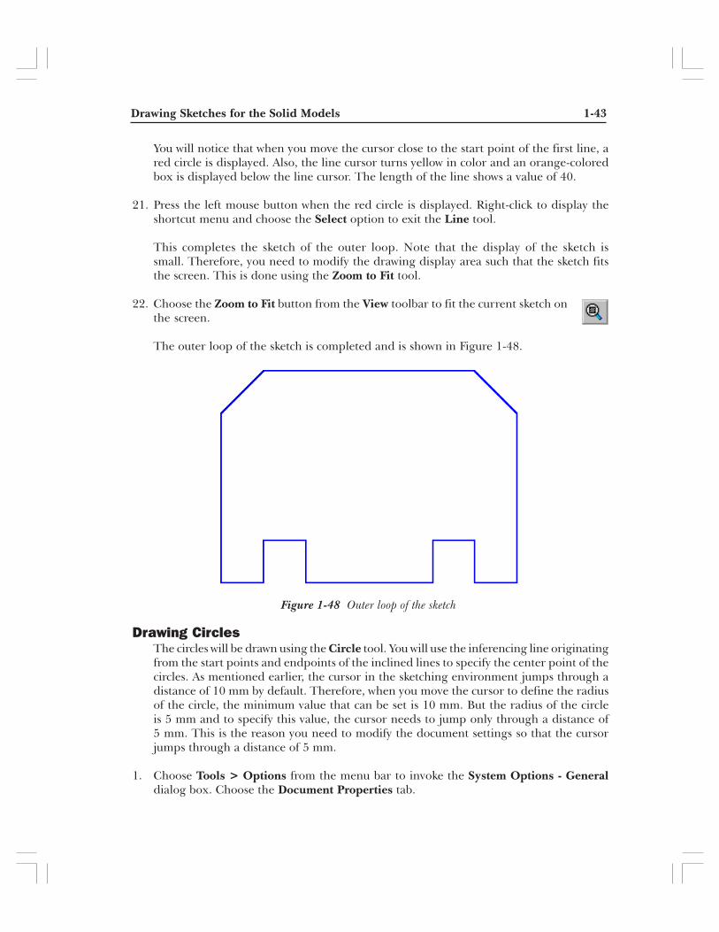
This completes the sketch of the outer loop. Note that the display of the sketch issmall. Therefore, you need to modify the drawing display area such that the sketch fitsthe screen. This is done using the Zoom to Fit tool.
22. Choose the Zoom to Fit button from the View toolbar to fit the current sketch onthe screen.
The outer loop of the sketch is completed and is shown in Figure 1-48.
Drawing CirclesThe circles will be drawn using the Circle tool. You will use the inferencing line originatingfrom the start points and endpoints of the inclined lines to specify the center point of thecircles. As mentioned earlier, the cursor in the sketching environment jumps through adistance of 10 mm by default. Therefore, when you move the cursor to define the radiusof the circle, the minimum value that can be set is 10 mm. But the radius of the circleis 5 mm and to specify this value, the cursor needs to jump only through a distance of5 mm. This is the reason you need to modify the document settings so that the cursorjumps through a distance of 5 mm.
1. Choose Tools > Options from the menu bar to invoke the System Options - Generaldialog box. Choose the Document Properties tab.
Figure 1-48 Outer loop of the sketch

1-44 SolidWorks for Designers
2. Select the Grid/Snap option from the area on the left to display the options related tolinear and angular units. Set the value of the Major grid spacing spinner to 50 andchoose OK.
Setting this value to 50 will force the cursor to jump through a distance of 5 mm insteadof 10 mm. Therefore, when you move the cursor now, the values shown on the cursor andthe coordinates of the points shown close to the lower right corner of the SolidWorkswindow will be in the increment of 5 mm.
3. Choose the Circle button from the Sketch CommandManager to invoke theCircle tool.
As the Select tool was active earlier, the cursor earlier was the arrow cursor. But when youinvoke the Circle tool, the arrow cursor will be replaced by the circle cursor.
4. Move the circle cursor close to the lower endpoint of the right inclined line and thenmove it toward the left. Remember that you will not press the left mouse button at thismoment.
An inferencing line is displayed generating from the lower endpoint of the right inclinedline. When you move the cursor toward the left, you will notice that at the point wherethe cursor is vertically in line with the upper endpoint of the right inclined line, anotherinferencing line is generated from the upper endpoint of the right inclined line. Thisinferencing line will intersect the inferencing line generated from the lower endpoint ofthe inclined line.
5. Press the left mouse button at the point where the inferencing lines from both theendpoints of the inclined lines intersect. Now, move the circle cursor toward the left todefine a circle.
6. Press the left mouse button when the radius of the circle displayed above the circle cursorshows a value of 5.
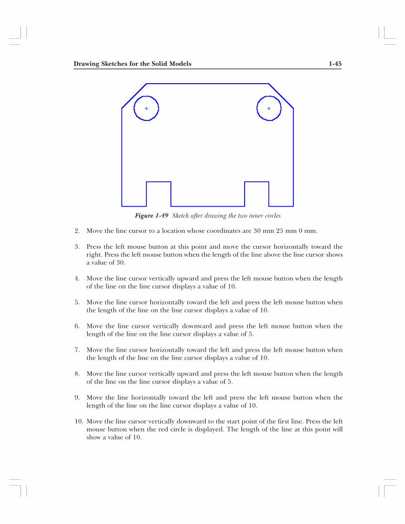
7. Similarly, draw the circle on the left using the inferencing lines generating from theendpoints of the left inclined line. The sketch after drawing the two circles inside theouter loop is shown in Figure 1-49.
8. Right-click in the drawing area and choose Select to exit the Circle tool.
Drawing the Sketch of the Inner CavityNext, you will draw the sketch of the inner cavity. To draw the sketch of the inner cavity,you will start drawing with the lower horizontal line.
1. Choose the Line button from the Sketch CommandManager. The arrowcursor is replaced by the line cursor.
Drawing Sketches for the Solid Models 1-45
2. Move the line cursor to a location whose coordinates are 30 mm 25 mm 0 mm.
3. Press the left mouse button at this point and move the cursor horizontally toward theright. Press the left mouse button when the length of the line above the line cursor showsa value of 30.
4. Move the line cursor vertically upward and press the left mouse button when the lengthof the line on the line cursor displays a value of 10.
5. Move the line cursor horizontally toward the left and press the left mouse button whenthe length of the line on the line cursor displays a value of 10.
6. Move the line cursor vertically downward and press the left mouse button when thelength of the line on the line cursor displays a value of 5.
7. Move the line cursor horizontally toward the left and press the left mouse button whenthe length of the line on the line cursor displays a value of 10.
8. Move the line cursor vertically upward and press the left mouse button when the lengthof the line on the line cursor displays a value of 5.
9. Move the line horizontally toward the left and press the left mouse button when thelength of the line on the line cursor displays a value of 10.
10. Move the line cursor vertically downward to the start point of the first line. Press the leftmouse button when the red circle is displayed. The length of the line at this point willshow a value of 10.
Figure 1-49 Sketch after drawing the two inner circles

1-46 SolidWorks for Designers
11. Right-click and choose Select from the shortcut menu. This completes the sketch forTutorial 1. The final completed sketch for Tutorial 1 is shown in Figure 1-50.
NoteBy default, the entity points are displayed at the endpoints when you sketch an entity. The entitypoints are dots at the endpoints of lines, arcs, splines, and so on. If you do not want the entitypoints to be displayed then choose Tools > Options from the menu bar to invoke the SystemOptions - General dialog box. Select the Sketch option from the left of this dialog box todisplay the option related to sketch. Select the Display entity points in part/assembly sketchescheck box and choose the OK button from this dialog box.
Saving the SketchIt is recommended that you create a separate folder for saving the tutorial files of thisbook. When you invoke the option to save a document, the default folder that is displayedis /My Documents. You will create a folder with the name SolidWorks in the My Documentsfolder and then create the folder of each chapter inside the SolidWorks folder. As a result,you can save the tutorials of a chapter in the folder of that chapter.
1. Choose the Save button from the Standard toolbar to invoke the Save As dialogbox. Create the SolidWorks folder inside the /My Documents folder and then createthe c01 folder inside the SolidWorks folder.
2. Enter the name of the document as c01-tut01.sldprt in the File name edit box and choosethe Save button. The document will be saved in the /My Documents/SolidWorks/c01 folder.
3. Close the document by choosing File > Close from the menu bar.
Figure 1-50 Final sketch for Tutorial 1
Drawing Sketches for the Solid Models 1-47
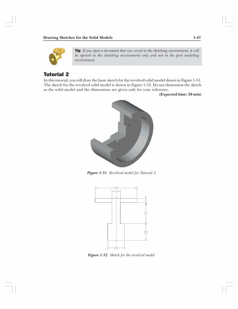
Tutorial 2In this tutorial, you will draw the basic sketch for the revolved solid model shown in Figure 1-51.The sketch for the revolved solid model is shown in Figure 1-52. Do not dimension the sketchas the solid model and the dimensions are given only for your reference.
(Expected time: 30 min)
Figure 1-52 Sketch for the revolved model
Figure 1-51 Revolved model for Tutorial 2
Tip. If you open a document that was saved in the sketching environment, it willbe opened in the sketching environment only and not in the part modelingenvironment.
1-48 SolidWorks for Designers
The steps that will be followed to complete this tutorial are listed below.
a. Start a new part document.b. Maximize the part document and then switch to the sketching environment.c. Modify the settings of the snap and grid so that the cursor jumps through a distance of
5 mm instead of 10 mm.d. Draw the sketch of the model using the Line tool, refer to Figure 1-53.e. Save the sketch and then close the document.
Starting a New Document1. Choose the New button from the Standard toolbar to invoke the New
SolidWorks Document dialog box.
2. The Part button is chosen by default in the New SolidWorks Document dialog box.Choose OK.
A new SolidWorks part document is opened. But the part document window is notmaximized in the SolidWorks window.
3. Choose the Maximize button available on the upper right corner of the part documentwindow to maximize the document window.
As mentioned earlier, when you open a new part document, the part modelingenvironment is active by default. But because you first need to draw the sketch of therevolved model, you need to invoke the sketching environment.
4. Choose the Sketch button from the Standard toolbar. The Edit SketchPropertyManager is displayed. Select the Front plane.
A red color origin is displayed and the Sketch CommandManager is displayed. Also, theconfirmation corner is displayed with the Exit Sketch and the Delete Sketch options onthe upper right corner of the drawing area. This suggests that the sketching environmentis activated.
Modifying the Snap and Grid Settings and the Dimensioning UnitsBefore you proceed with drawing the sketch, you need to modify the grid and snapsettings so that you can make the cursor jump through a distance of 5 mm instead of10 mm, which is the default value.
1. Choose Tools > Options from the menu bar to invoke the System Options - Generaldialog box. Choose the Document Properties tab.
2. Select the Grid/Snap option from the area on the left to display the options related tolinear and angular units. Set the value of the Major grid spacing spinner to 50. Makesure the value of the Minor-lines per major spinner is 10. Choose OK to close the dialogbox.

Drawing Sketches for the Solid Models 1-49
The coordinates close to the lower left corner of the SolidWorks window will show an incrementof 5 mm instead of the default increment of 10 mm when you exit the dialog box.
3. Make sure the Snap to points check box in the Snap area is selected.
If you selected a unit other than millimeter to measure the length while installingSolidWorks, you need to change the unit for the current drawing.
4. Select the Units option from the area on the left of the Document Properties - Grid/Snap dialog box.
5. Select millimeters from the drop-down list available in the Length units area and Degreesfrom the drop-down list available in the Angular units area. Choose the OK button aftermaking the necessary settings.
Drawing the SketchAs evident from Figure 1-52, the sketch will be drawn using the Line tool. You will startdrawing the sketch from the lower left corner of the sketch.
1. Choose the Line button from the Sketch CommandManager. The arrowcursor will be replaced by the line cursor.
2. Move the line cursor to a location whose coordinates are 40 mm 0 mm 0 mm.
An inferencing line originating from the origin is displayed.
3. Press the left mouse button down at this point and move the cursor horizontally towardthe right. Press the left mouse button again when the length of the line above the linecursor shows a value of 20.
4. Move the line cursor vertically upward and press the left mouse button when the lengthof the line on the line cursor displays a value of 20.
5. Move the cursor horizontally toward the left and press the left mouse button when thelength of the line on the line cursor displays a value of 5.
6. Move the line cursor vertically upward and press the left mouse button when the lengthof the line on the line cursor displays a value of 25.
7. Move the line cursor horizontally toward the right and press the left mouse button whenthe length of the line on the line cursor displays a value of 20.
8. Move the line cursor vertically upward and press the left mouse button when the lengthof the line on the line cursor displays a value of 5.
9. Move the line cursor horizontally toward the left and press the left mouse button whenthe length of the line on the line cursor displays a value of 50.

1-50 SolidWorks for Designers
10. Move the line cursor vertically downward and press the left mouse button when thelength of the line on the line cursor displays a value of 5.
11. Move the line cursor horizontally toward the right and press the left mouse button whenthe length of the line on the line cursor displays a value of 20.
12. Move the line cursor vertically downward and press the left mouse button when thelength of the line on the line cursor displays a value of 25.
13. Move the line cursor horizontally toward the left and press the left mouse button whenthe length of the line on the line cursor displays a value of 5.
14. Move the line cursor vertically downward to the start point of the first line. Press the leftmouse button when the red circle is displayed.
The length of the line at this point will be 20 mm
15. Right-click and choose Select from the shortcut menu.
The sketch is completed but does not fit the screen. Therefore, you need to modify thedisplay area such that the sketch fits the screen.
16. Choose the Zoom to Fit button from the View toolbar to fit the sketch on thescreen. The completed sketch for Tutorial 2 is shown in Figure 1-53.
Figure 1-53 Final sketch for Tutorial 2
Tip. You will notice that the bottom horizontal line in the sketch is black in colorand the remaining lines are blue in color. In the next chapter, you will learn aboutthe reason why some entities in the sketch have a different color.
Drawing Sketches for the Solid Models 1-51
Saving the Sketch1. Choose the Save button from the Standard toolbar to invoke the Save As dialog
box.
2. Enter the name of the document as c01-tut02.sldprt in the File name edit box and choosethe Save button.
The document will be saved in the /My Documents/SolidWorks/c01 folder.
3. Close the document by choosing File > Close from the menu bar.
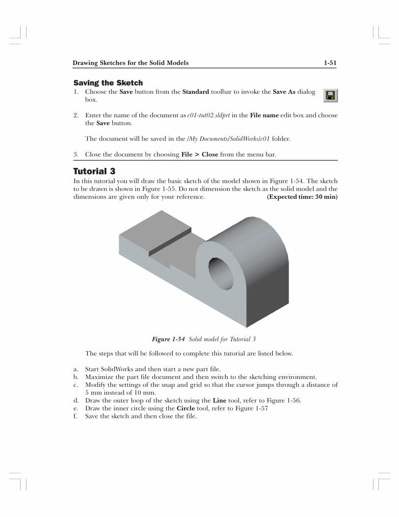
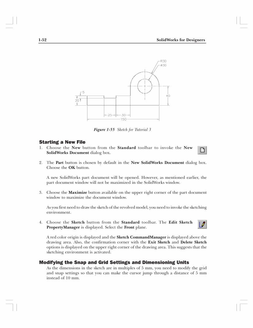
Tutorial 3In this tutorial you will draw the basic sketch of the model shown in Figure 1-54. The sketchto be drawn is shown in Figure 1-55. Do not dimension the sketch as the solid model and thedimensions are given only for your reference. (Expected time: 30 min)
The steps that will be followed to complete this tutorial are listed below.
a. Start SolidWorks and then start a new part file.b. Maximize the part file document and then switch to the sketching environment.c. Modify the settings of the snap and grid so that the cursor jumps through a distance of
5 mm instead of 10 mm.d. Draw the outer loop of the sketch using the Line tool, refer to Figure 1-56.e. Draw the inner circle using the Circle tool, refer to Figure 1-57f. Save the sketch and then close the file.
Figure 1-54 Solid model for Tutorial 3
1-52 SolidWorks for Designers
Starting a New File1. Choose the New button from the Standard toolbar to invoke the New
SolidWorks Document dialog box.
2. The Part button is chosen by default in the New SolidWorks Document dialog box.Choose the OK button.
A new SolidWorks part document will be opened. However, as mentioned earlier, thepart document window will not be maximized in the SolidWorks window.
3. Choose the Maximize button available on the upper right corner of the part documentwindow to maximize the document window.
As you first need to draw the sketch of the revolved model, you need to invoke the sketchingenvironment.
4. Choose the Sketch button from the Standard toolbar. The Edit SketchPropertyManager is displayed. Select the Front plane.
A red color origin is displayed and the Sketch CommandManager is displayed above thedrawing area. Also, the confirmation corner with the Exit Sketch and Delete Sketchoptions is displayed on the upper right corner of the drawing area. This suggests that thesketching environment is activated.
Modifying the Snap and Grid Settings and Dimensioning UnitsAs the dimensions in the sketch are in multiples of 5 mm, you need to modify the gridand snap settings so that you can make the cursor jump through a distance of 5 mminstead of 10 mm.
Figure 1-55 Sketch for Tutorial 3

Drawing Sketches for the Solid Models 1-53
1. Choose Tools > Options from the menu bar to invoke the System Options - Generaldialog box. Choose the Document Properties tab.
2. Select the Grid/Snap option from the area on the left to display the options related tolinear and angular units. Set the value of the Major grid spacing spinner to 50 andchoose OK. Make sure the value of the Minor-lines per major spinner is 10.
The coordinates displayed close to the lower left corner of the SolidWorks window willshow an increment of 5 mm instead of the default increment of 10 mm when you closethe dialog box.
3. If you selected a unit other than millimeter to measure the length while installingSolidWorks, select the Units option from the area on the left of the Document Properties- Grid/Snap dialog box. Select millimeters from the drop-down list available in the Lengthunits area and Degrees from the drop-down list available in the Angular units area.
4. Choose OK to close the dialog box.
Drawing the Outer LoopAs evident from Figure 1-55, the sketch consists of an outer loop and an inner circle.Therefore, this sketch will be drawn using the Line and the Circle tools. You will startdrawing from the lower left corner of the sketch. As the length of the lower horizontalline is 150 mm, you need to modify the drawing display area such that the drawing areain the first quadrant is increased. This can be done using the Pan tool.
1. Choose the Pan button from the View toolbar. The arrow cursor will be replacedby the pan cursor.
2. Press and hold the left mouse button down and drag the cursor toward the bottom leftcorner of the screen.
You will notice that the origin also moves toward the bottom left corner of the screen,thus increasing the drawing area in the first quadrant.
3. After dragging the origin close to the lower left corner, release the left mouse button.
4. Choose the Line button from the Sketch CommandManager.
The pan cursor will be replaced by the line cursor.
5. Move the line cursor to a location whose coordinates are 40 mm 0 mm 0 mm.
An inferencing line originating from the origin will be displayed.
6. Press the left mouse button down at this point and move the cursor horizontally towardthe right. Press the left mouse button again when the length of the line above the linecursor shows a value of 150.

1-54 SolidWorks for Designers
7. Move the line cursor vertically upward and press the left mouse button when the lengthof the line on the line cursor displays a value of 40.
The next entity that has to be drawn is a tangent arc. As mentioned earlier, you can drawthe tangent arc using the Line tool also. Drawing arcs from within the Line tool is arecommended method when you need to draw a sketch that is a combination of lines andarcs. This increases the productivity by reducing the time taken in invoking the tools fordrawing an arc and then invoking the Line tool to draw lines.
8. Move the line cursor away from the endpoint of the last line and then move it back to theendpoint.
The arc mode is invoked and the line cursor is replaced by the arc cursor. Also, the ArcPropertyManager is displayed in place of the Line PropertyManager.
9. Move the arc cursor vertically upward to a small distance. A dotted reference line isdisplayed.
10. When the dotted line is displayed, move the cursor toward the left.
You will notice that a tangent arc is being drawn. The angle of the tangent arc and itsradius are displayed above the arc cursor.
11. Press the left mouse button when the angle value above the arc cursor shows 180 and theradius shows a value of 30 to complete the arc.
The required tangent arc is drawn. As mentioned earlier, the line mode is automaticallyinvoked after you have drawn the arc using the Line tool. Therefore, the arc cursor willbe replaced by the line cursor and the Arc PropertyManager will be replaced by theLine PropertyManager.
12. Move the line cursor vertically downward and press the left mouse button when thelength of the line on the line cursor displays a value of 20.
13. Move the line cursor horizontally toward the left and press the left mouse button whenthe length of the line on the line cursor displays a value of 30.
14. Move the line cursor vertically downward and press the left mouse button when thelength of the line on the line cursor displays a value of 5.
15. Move the line cursor horizontally toward the left and press the left mouse button whenthe length of the line on the line cursor displays a value of 25.
16. Move the line cursor vertically upward and press the left mouse button when the lengthof the line on the line cursor displays a value of 5.
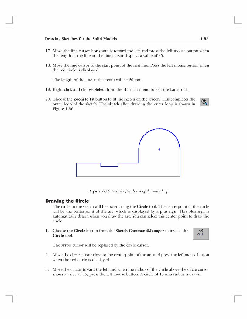
Drawing Sketches for the Solid Models 1-55
17. Move the line cursor horizontally toward the left and press the left mouse button whenthe length of the line on the line cursor displays a value of 35.
18. Move the line cursor to the start point of the first line. Press the left mouse button whenthe red circle is displayed.
The length of the line at this point will be 20 mm
19. Right-click and choose Select from the shortcut menu to exit the Line tool.
20. Choose the Zoom to Fit button to fit the sketch on the screen. This completes theouter loop of the sketch. The sketch after drawing the outer loop is shown inFigure 1-56.
Drawing the CircleThe circle in the sketch will be drawn using the Circle tool. The centerpoint of the circlewill be the centerpoint of the arc, which is displayed by a plus sign. This plus sign isautomatically drawn when you draw the arc. You can select this center point to draw thecircle.
1. Choose the Circle button from the Sketch CommandManager to invoke theCircle tool.
The arrow cursor will be replaced by the circle cursor.
2. Move the circle cursor close to the centerpoint of the arc and press the left mouse buttonwhen the red circle is displayed.
3. Move the cursor toward the left and when the radius of the circle above the circle cursorshows a value of 15, press the left mouse button. A circle of 15 mm radius is drawn.
Figure 1-56 Sketch after drawing the outer loop
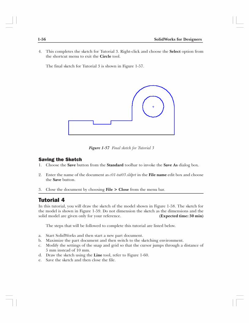
1-56 SolidWorks for Designers
4. This completes the sketch for Tutorial 3. Right-click and choose the Select option fromthe shortcut menu to exit the Circle tool.
The final sketch for Tutorial 3 is shown in Figure 1-57.
Saving the Sketch1. Choose the Save button from the Standard toolbar to invoke the Save As dialog box.
2. Enter the name of the document as c01-tut03.sldprt in the File name edit box and choosethe Save button.
3. Close the document by choosing File > Close from the menu bar.
Tutorial 4In this tutorial, you will draw the sketch of the model shown in Figure 1-58. The sketch forthe model is shown in Figure 1-59. Do not dimension the sketch as the dimensions and thesolid model are given only for your reference. (Expected time: 30 min)
The steps that will be followed to complete this tutorial are listed below.
a. Start SolidWorks and then start a new part document.b. Maximize the part document and then switch to the sketching environment.c. Modify the settings of the snap and grid so that the cursor jumps through a distance of
5 mm instead of 10 mm.d. Draw the sketch using the Line tool, refer to Figure 1-60.e. Save the sketch and then close the file.
Figure 1-57 Final sketch for Tutorial 3
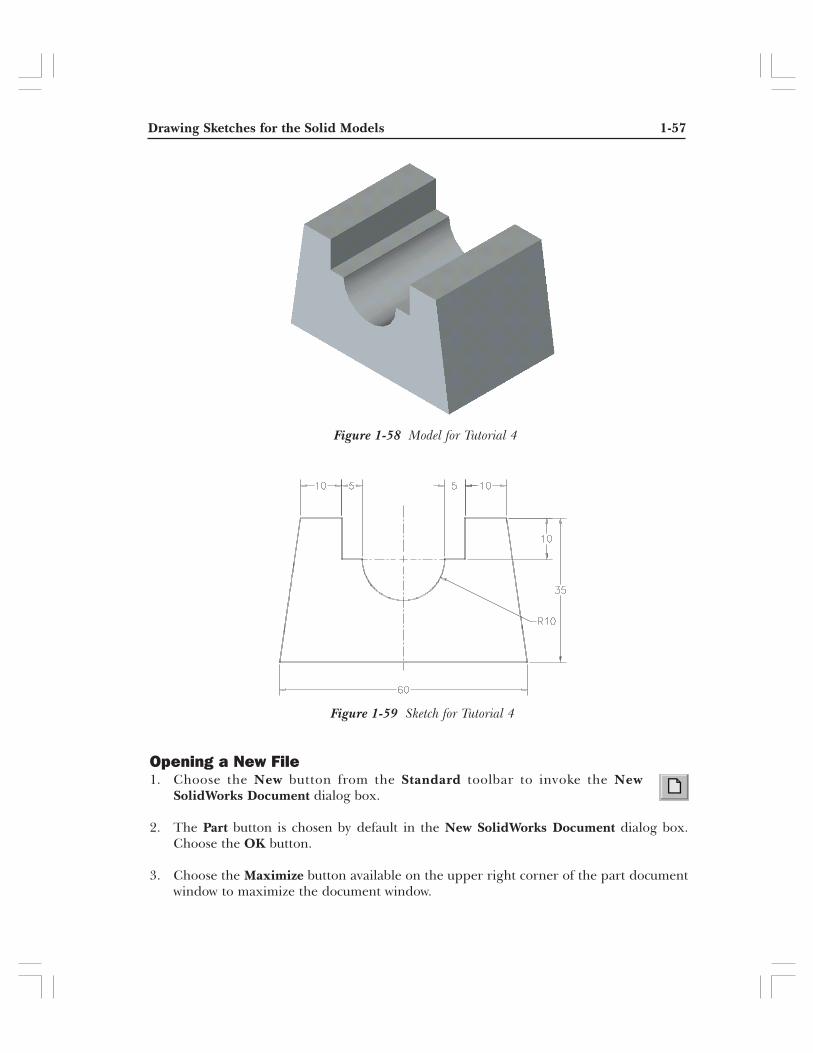
Drawing Sketches for the Solid Models 1-57
Opening a New File1. Choose the New button from the Standard toolbar to invoke the New
SolidWorks Document dialog box.
2. The Part button is chosen by default in the New SolidWorks Document dialog box.Choose the OK button.
3. Choose the Maximize button available on the upper right corner of the part documentwindow to maximize the document window.
Figure 1-59 Sketch for Tutorial 4
Figure 1-58 Model for Tutorial 4
1-58 SolidWorks for Designers
As you first need to draw the sketch of the model, you need to invoke the sketchingenvironment.
4. Choose the Sketch button from the Standard toolbar and select the Front planeto invoke the sketching environment.
Modifying the Snap and Grid Settings and Dimensioning UnitsAs evident in Figure 1-59, the dimensions in the sketch are in the multiples of 5 mm.Therefore, you need to modify the grid and snap settings so that the cursor jumps througha distance of 5 mm instead of 10 mm.
1. Choose Tools > Options from the menu bar to invoke the System Options - Generaldialog box. Choose the Document Properties tab.
2. Select the Grid/Snap option from the area on the left to display the options related tolinear and angular units. Set the value of the Major grid spacing spinner to 50 andchoose OK. Make sure the value of the Minor-lines per major spinner is 10.
The coordinates displayed close to the lower left corner of the SolidWorks window showsan increment of 5 mm when you close this dialog box.
3. If you selected a unit other than millimeter to measure the length while installingSolidWorks, select the Units option from the area on the left of the Document Properties- Grid/Snap dialog box. Select millimeters from the drop-down list available in the Lengthunits area and Degrees from the drop-down list available in the Angular units area.
4. Choose OK to close the dialog box.
Drawing the SketchThe sketch will be drawn using the Line tool. The arc in the sketch will also be drawnusing the same tool. You will start drawing from the lower left corner of the sketch.
1. Choose the Line button from the Sketch CommandManager.
The arrow cursor is replaced by the line cursor.
2. Move the line cursor to a location whose coordinates are 30 mm 0 mm 0 mm.
An inferencing line originating from the origin is displayed.
3. Press the left mouse button at this point and move the cursor horizontally toward theright. Press the left mouse button again when the length of the line above the line cursorshows a value of 60.
The bottom horizontal line of 60 mm length is drawn.

Drawing Sketches for the Solid Models 1-59
4. Choose the Zoom to Fit button from the View toolbar to increase the display ofthe line that is drawn.
As mentioned earlier, you can also invoke the drawing display tools while you are insidesome other tool. After modifying the drawing display, the tool that was active beforeinvoking the drawing display tool will be restored and you can continue using that tool.Therefore, after the drawing display area is modified, the Line tool will be restored andyou can continue drawing lines.
5. Move the line cursor along a direction that makes an angle close to 98-degree with thepositive X axis direction. The angle can be checked from the spinner above the Delta Xspinner in the Line PropertyManager.
6. When the Delta X spinner shows a value of 5 and Delta Y spinner shows a value of 35,press the left mouse button.
The length of the line displayed above the line cursor at this point will be 35.36.
7. Move the line cursor horizontally toward the left and press the left mouse button whenthe length of the line above the line cursor shows a value of 10.
8. Move the line cursor vertically downward and press the left mouse button when thelength of the line above the line cursor shows a value of 10.
9 Move the line cursor horizontally toward the left and press the left mouse button whenthe length of the line above the line cursor shows a value of 5.
Next, you need to draw the arc that is normal to the last line.
10. Move the line cursor away from the endpoint of the last line and then move it back closeto the endpoint.
The arc mode will be invoked and the line cursor will be replaced by the arc cursor. Also,the Line PropertyManager will be replaced by the Arc PropertyManager.
11. Move the arc cursor vertically downward through a small distance.
A dotted line will be displayed.
12. When the dotted line is displayed, move the arc cursor toward the left.
You will notice that a normal arc is being drawn and the angle and radius of the arc isdisplayed above the arc cursor.
13. Press the left mouse button when the angle value on the arc cursor is 180 and the radiusvalue is 10. An arc normal to the last line will be drawn and the line mode will be activated.
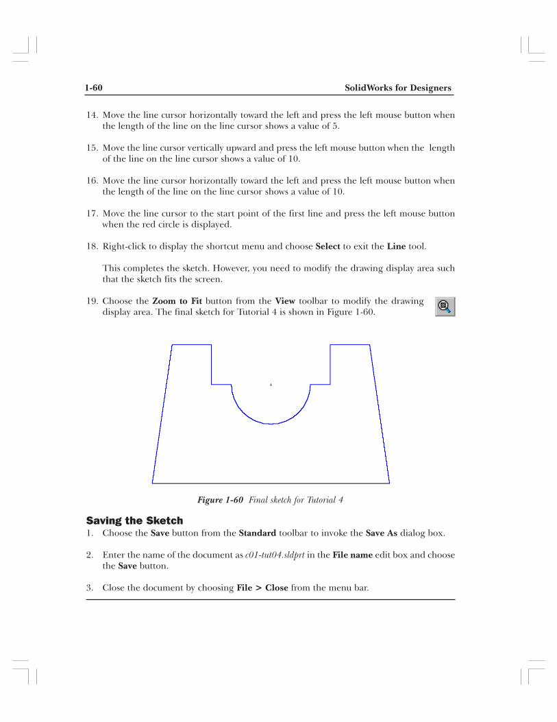
1-60 SolidWorks for Designers
Figure 1-60 Final sketch for Tutorial 4
14. Move the line cursor horizontally toward the left and press the left mouse button whenthe length of the line on the line cursor shows a value of 5.
15. Move the line cursor vertically upward and press the left mouse button when the lengthof the line on the line cursor shows a value of 10.
16. Move the line cursor horizontally toward the left and press the left mouse button whenthe length of the line on the line cursor shows a value of 10.
17. Move the line cursor to the start point of the first line and press the left mouse buttonwhen the red circle is displayed.
18. Right-click to display the shortcut menu and choose Select to exit the Line tool.
This completes the sketch. However, you need to modify the drawing display area suchthat the sketch fits the screen.
19. Choose the Zoom to Fit button from the View toolbar to modify the drawingdisplay area. The final sketch for Tutorial 4 is shown in Figure 1-60.
Saving the Sketch1. Choose the Save button from the Standard toolbar to invoke the Save As dialog box.
2. Enter the name of the document as c01-tut04.sldprt in the File name edit box and choosethe Save button.
3. Close the document by choosing File > Close from the menu bar.

Drawing Sketches for the Solid Models 1-61
SELF-EVALUATION TESTAnswer the following questions and then compare your answers with the answers given atthe end of this chapter.
1. The base feature of any design is a sketched feature and is created by drawing the sketch.(T/F)
2. You can also invoke the 3Pt Arc tool from within the Line tool. (T/F)
3. By default, the cursor jumps through a distance of 5 mm. (T/F)
4. When you save a file in the sketching environment, it is opened in the part modelingenvironment when you open it for the next time. (T/F)
5. You can convert a sketched entity into a construction entity by selecting the __________check box provided in the PropertyManager.
6. To draw a rectangle at an angle, you need to use the __________ tool.
7. The __________ are the temporary lines that are used to track a particular point on thescreen.
8. You can also invoke the __________ tool or exit a sketching tool by pressing the ESC key.
9. When you select a tangent entity to draw a tangent arc, the __________ relation is appliedbetween the start point of the arc and the tangent entity.
10. The rectangle is considered as a combination of individual __________.
REVIEW QUESTIONSAnswer the following questions.
1. The 3 point arcs are the ones that are drawn by defining the start point of the arc, theendpoint of the arc, and a point on the arc. (T/F)
2. You can also delete the sketched entities by selecting them and choosing the Deleteoption from the shortcut menu that is displayed upon right-clicking. (T/F)
3. The origin is a blue-colored icon that is displayed in the middle of the sketcher screen.(T/F)
4. In SolidWorks, circles are drawn by specifying the centerpoint of the circle and thenentering the radius of the circle in the dialog box that is displayed. (T/F)
5. When you open a new SolidWorks document, it is not maximized in the SolidWorkswindow. (T/F)

1-62 SolidWorks for Designers
6. In SolidWorks, a polygon is considered as a combination of which of the following entities.
(a) Lines (b) Arcs(c) Splines (d) None
7. Which one of the following options is not displayed in the New SolidWorks Documentdialog box?
(a) Part (b) Assembly(c) Drawing (d) Sketch
8. Which one of the following entities will not be considered while converting a sketch intoa feature?
(a) Sketched circles (b) Sketched lines(c) Construction lines (d) None
9. When you select a line of the rectangle, which one of the following PropertyManagerwill be displayed?
(a) Line PropertyManager (b) Line/Rectangle PropertyManager(c) Rectangle PropertyManager (d) None
10. While drawing an elliptical arc, which one of the following PropertyManager will bedisplayed?
(a) Arc PropertyManager (b) Ellipse PropertyManager(c) Elliptical Arc PropertyManager (d) None
EXERCISES
Exercise 1Draw the sketch of the model shown in Figure 1-61. The sketch to be drawn is shown inFigure 1-62. Do not dimension the sketch as the solid model and the dimensions are givenonly for your reference. (Expected time: 30 min)
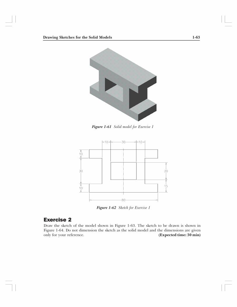
Drawing Sketches for the Solid Models 1-63
Figure 1-62 Sketch for Exercise 1
Figure 1-61 Solid model for Exercise 1
Exercise 2Draw the sketch of the model shown in Figure 1-63. The sketch to be drawn is shown inFigure 1-64. Do not dimension the sketch as the solid model and the dimensions are givenonly for your reference. (Expected time: 30 min)

1-64 SolidWorks for Designers
Figure 1-64 Sketch for Exercise 2
Figure 1-63 Solid model for Exercise 2
Answers to Self-Evaluation Test1. T, 2. T, 3. F, 4. F, 5. For Construction, 6. Parallelogram, 7. inferencing lines, 8. Select,9. Tangent, 10. lines