chapter 1 bu erless and minimally-bu ered de ection routing
TRANSCRIPT

Chapter 1
Bufferless and Minimally-BufferedDeflection Routing
Chris Fallin, Greg Nazario, Xiangyao Yu, Kevin Chang, RachataAusavarungnirun, Onur Mutlu
Abstract A conventional Network-on-Chip (NoC) router uses input buffersto store in-flight packets. These buffers improve performance, but consumesignificant power. It is possible to bypass these buffers when they are empty,reducing dynamic power, but static buffer power remains, and when buffersare utilized, dynamic buffer power remains as well. To improve energy effi-ciency, bufferless deflection routing removes input buffers, and instead usesdeflection (misrouting) to resolve contention. Bufferless deflection routing isable to provide similar network performance to conventional buffered routingwhen the network carries light to moderate traffic, because deflections arerelatively rare. However, at high network load, deflections cause unnecessarynetwork hops, wasting power and reducing performance. In order to avoidsome deflections and recover some performance, recent work has proposed toadd a small buffer which holds only flits that contend with others and wouldhave been deflected. This minimally-buffered deflection (MinBD) router im-proves performance relative to bufferless deflection routing without incurringthe cost of a large buffer, because it can make more efficient use of a smallbuffer. The result is a router design which is more energy-efficient than priorbuffered, bufferless, and hybrid router designs.
Chris Fallin, Greg Nazario, Kevin Chang, Rachata Ausavarungnirun, and Onur MutluCarnegie Mellon University
{cfallin,gnazario,kevincha,rausavar,onur}@cmu.edu
Xiangyao YuMassachusetts Institute of [email protected]
1

2 Fallin et al.
1.1 Introduction
A network-on-chip is a first-order component of current and future multi-core and manycore CMPs (Chip Multiprocessors) [12], and its design can becritical for system performance. As core counts continue to rise, NoCs withdesigns such as 2D-mesh (e.g., Tilera [51] and Intel Terascale [28]) are ex-pected to become more common to provide adequate performance scaling.Unfortunately, packet-switched NoCs are projected to consume significantpower. In the Intel Terascale 80-core chip, 28% of chip power is consumed bythe NoC [28]; for MIT RAW, 36% [46]; for the Intel 48-core SCC, 10% [6].NoC energy efficiency is thus an important design goal [4, 5].
Mechanisms have been proposed to make conventional input-buffered NoCrouters more energy-efficient (i.e., use less energy per unit of performance).For example, bypassing empty input buffers [37, 50] reduces some dynamicbuffer power, but static power remains.1 Such bypassing is also less effectivewhen buffers are not frequently empty. Bufferless deflection routers [17, 38]remove router input buffers completely (hence eliminating their static anddynamic power) to reduce router power. When two flits2 contend for a singlerouter output, one must be deflected to another output. Thus, a flit neverrequires a buffer in a router. By controlling which flits are deflected, a buffer-less deflection router can ensure that all traffic is eventually delivered. Re-moving buffers yields simpler and more energy-efficient NoC designs: e.g.,CHIPPER [17] reduces average network power by 54.9% in a 64-node systemcompared to a conventional buffered router.
Unfortunately, at high network load, deflection routing reduces perfor-mance and efficiency. This is because deflections occur more frequently whenmany flits contend in the network. Each deflection sends a flit further fromits destination, causing unnecessary link and router traversals. Relative toa buffered network, a bufferless network with a high deflection rate wastesenergy, and suffers worse congestion, because of these unproductive networkhops. In contrast, a buffered router is able to hold flits (or packets) in its inputbuffers until the required output port is available, incurring no unnecessaryhops. Thus, a buffered network can sustain higher performance at peak load,but at the cost of large buffers, which can consume significant power and diearea.
The best interconnect design would obtain the energy efficiency of thebufferless approach with the high performance of the buffered approach. Nei-ther purely bufferless deflection routing nor conventional input-buffered rout-ing satisfy this goal. Ideally, a router would contain only a small amount of
1 One recent estimate indicates that static power (of buffers and links) could constitute
80–90% of interconnect power in future systems [7].2 In a conventional bufferless deflection network, flits (several of which make up one packet)
are independently routed, unlike most buffered networks, where a packet is the smallestindependently-routed unit of traffic.

1 Bufferless and Minimally-Buffered Deflection Routing 3
buffering, and would use this buffer space only for those flits that actuallyrequire it, rather than all flits that arrive.
In this chapter, we discuss minimally-buffered deflection routing (MinBD) [20],a router design which combines both bufferless and buffered paradigms in afine-grained and efficient way. MinBD uses deflection routing, but also in-corporates a small buffer. The router does not switch between modes, butinstead, always operates in a minimally-buffered deflection mode, and canbuffer or deflect any given flit. When a flit first arrives, it does not entera buffer, but travels straight to the routing logic. If two flits contend forthe same output, the routing logic chooses one to deflect, as in a bufferlessrouter. However, the router can choose to buffer up to one deflected flit percycle rather than deflecting it. This fine-grained buffering-deflection hybridapproach significantly reduces deflection rate (by 54% [20]), and improvesperformance, as we show. It also incurs only a fraction of the energy costof a conventional buffered router, because only a relatively small fraction offlits are buffered (20% of all flits). MinBD provides higher energy efficiencywhile also providing high performance, compared to a comprehensive set ofbaseline router designs. In this chapter, we will discuss:
• Bufferless deflection routing [17, 38], which uses deflection in place ofbuffering to resolve contention between flits. We will introduce the ba-sic design of the BLESS [38] and CHIPPER [17] routers, and discuss thedeflection arbitration, livelock freedom, and packet reassembly problemsassociated with bufferless routing.
• A new NoC router, MinBD (minimally-buffered deflection routing) [20],that combines deflection routing with minimal buffering. The router per-forms deflection routing, but can choose to buffer up to one flit per cyclein a small side buffer, which significantly reduces deflection rate and en-hances performance compared to a pure bufferless design while requiringsmaller buffer space than a conventional input-buffered design.
• An evaluation of MinBD against aggressive NoC router baselines: a two-cycle virtual channel buffered router [11] with empty buffer bypassing [37,50] at three buffer capacities (with a sensitivity analysis over many moreconfigurations), CHIPPER [17], and a hybrid bufferless-buffered design,AFC [29], with SPEC CPU2006 [45] multiprogrammed workloads on 16-and 64-node CMP systems. From our results, we conclude that MinBDhas the best energy efficiency over all of these prior design points, whileachieving competitive system throughput and logic critical path delay withthe input-buffered router (the best-performing baseline) and competitivearea and power consumption with the pure-bufferless router (the smallestand most power-efficient baseline).
4 Fallin et al.
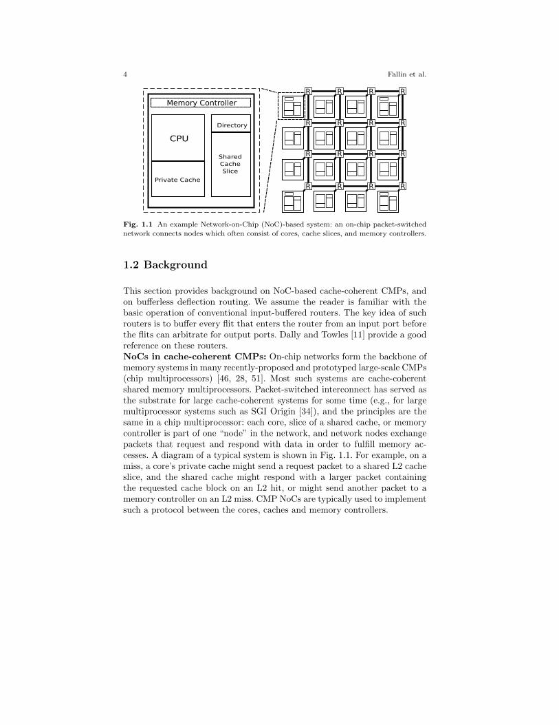
Fig. 1.1 An example Network-on-Chip (NoC)-based system: an on-chip packet-switchednetwork connects nodes which often consist of cores, cache slices, and memory controllers.
1.2 Background
This section provides background on NoC-based cache-coherent CMPs, andon bufferless deflection routing. We assume the reader is familiar with thebasic operation of conventional input-buffered routers. The key idea of suchrouters is to buffer every flit that enters the router from an input port beforethe flits can arbitrate for output ports. Dally and Towles [11] provide a goodreference on these routers.NoCs in cache-coherent CMPs: On-chip networks form the backbone ofmemory systems in many recently-proposed and prototyped large-scale CMPs(chip multiprocessors) [46, 28, 51]. Most such systems are cache-coherentshared memory multiprocessors. Packet-switched interconnect has served asthe substrate for large cache-coherent systems for some time (e.g., for largemultiprocessor systems such as SGI Origin [34]), and the principles are thesame in a chip multiprocessor: each core, slice of a shared cache, or memorycontroller is part of one “node” in the network, and network nodes exchangepackets that request and respond with data in order to fulfill memory ac-cesses. A diagram of a typical system is shown in Fig. 1.1. For example, on amiss, a core’s private cache might send a request packet to a shared L2 cacheslice, and the shared cache might respond with a larger packet containingthe requested cache block on an L2 hit, or might send another packet to amemory controller on an L2 miss. CMP NoCs are typically used to implementsuch a protocol between the cores, caches and memory controllers.

1 Bufferless and Minimally-Buffered Deflection Routing 5
1.2.1 Bufferless Deflection Routing in NoCs: BLESS
Bufferless Deflection Routers: Bufferless deflection routing was first pro-posed by Baran [3]. Bufferless deflection routing operates without in-networkbuffering. Instead, a unit of traffic continuously moves between network nodesuntil it reaches its destination. When contention occurs for a network link, abufferless deflection router sends some traffic to another output link instead,deflecting it. Hence, the use of buffers is replaced by occasional extra linktraversals.
Bufferless deflection routing has found renewed interest in NoC design be-cause on-chip wires (hence, network links) are relatively cheap, in contrast tobuffers, which consume significant die area and leakage power [4, 5, 7, 29, 38].Several evaluations of bufferless NoC design [17, 26, 29, 38] have demonstratedthat removing the buffers in NoC routers, and implementing a routing strat-egy which operates without the need for buffers (such as the one we describebelow), yield energy-efficiency improvements because occasional extra linktraversals due to deflections consume relatively less energy than the dynamicenergy used to buffer traffic at every network hop and the static energyconsumed whenever a buffer is turned on. (Our motivational experimentsin §1.3 demonstrate the performance and energy impact of such a networkdesign in more detail.) Although other solutions exist to reduce the energyconsumption of buffers, such as dynamic buffer bypassing [37, 50] (whichwe also incorporate into our baseline buffered-router design in this chapter),bufferless deflection routing achieves additional savings in energy and areaby completely eliminating the buffers.
One recent work proposed BLESS [38], a router design that implementsbufferless deflection routing, which we describe here. The fundamental unitof routing in a BLESS network is the flit, a packet fragment transferred byone link in one cycle. Flits are routed independently in BLESS.3 Becauseflits are routed independently, they must be reassembled after they are re-ceived. BLESS assumes the existence of sufficiently-sized reassembly buffersat each node in order to reconstruct arriving flits into packets. (Later work,CHIPPER [17], addresses the reassembly problem explicitly, as we discussbelow.)Deflection Routing Arbitration: The basic operation of a BLESS buffer-less deflection router is simple. In each cycle, flits arriving from neighborrouters enter the router pipeline. Because the router contains no buffers, flitsare stored only in pipeline registers, and must leave the router at the endof the pipeline. Thus, the router must assign every input flit to some out-put port. When two flits request the same output port according to their
3 BLESS’ independent flit routing stands in contrast to conventional wormhole or VC(virtual-channel) routing, in which a packet’s body flits always follow its head flits: because
a deflection can occur in any cycle, any flit in a BLESS network could be separated fromthe rest of its packet and must carry its own routing information. This is described more
fully in Moscibroda and Mutlu [38].

6 Fallin et al.
ordinary routing function, the router deflects one of them to another port(this is always possible, as long as the router has as many outputs as inputs).BLESS performs this router output port assignment in two stages: flit rank-ing and port selection [38]. In each cycle, the flits that arrive at the routerare first ranked in a priority order (chosen in order to ensure livelock-freeoperation, as we describe below). At the same time, the router computes alist of productive output ports (i.e., ports which would send the flit closer toits destination) for each flit. Once the flit ranking and each flits’ productiveoutput ports are available, the router assigns a port to each flit, starting fromthe highest-ranked flit and assigning ports to flits one at a time. Each flit ob-tains a productive output port if one is still available, and is “deflected” toany available output port otherwise. Because there are as many output portsas input ports, and only the flits arriving on the input ports in a given cycleare considered, this process never runs out of output ports and can alwaysassign each flit to some output. Hence, no buffering is needed, because everyflit is able to leave the router at the end of the router pipeline.Livelock freedom in BLESS: Although a BLESS router ensures that a flitis always able to take a network hop to some other router, a deflection takes aflit further from its destination, and such a flit will have to work its way even-tually to its destination. In such a network design, explicit care must be takento ensure that all flits eventually arrive at their destinations (i.e., that no flitcircles, or gets stuck, in the network forever). This property is called livelockfreedom. Note that conventional virtual channel-buffered routers, which bufferflits at every network hop, are livelock-free simply because they never deflectflits: rather, whenever a flit leaves a router and traverses a link, it alwaysmoves closer toward its destination (this is known as minimal routing [11]).
BLESS ensures livelock freedom by employing a priority scheme calledOldest-First [38]. Oldest-First prioritization is a total order over all flits basedon each flit’s age (time it has spent in the network). If two flits have the sameage (entered the network in the same cycle), then the tie is broken with otherheader fields (such as sender ID) which uniquely identify the flit. This totalpriority order leads to livelock-free operation in a simple way: there mustbe one flit which is the oldest, and thus has the highest priority. This flitis always be prioritized during flit-ranking at every router it visits. Thus, itobtains its first choice of output port and is never deflected. Because it isnever deflected, the flit always moves closer toward its destination, and willeventually arrive. Once it arrives, it is no longer contending with other flitsin the network, and some other flit is the oldest flit. The new oldest flit isguaranteed to arrive likewise. Inductively, all flits eventually arrive.Flit injection and ejection: A BLESS router must inject new flits intothe network when a node generates a packet, and it must remove a flit fromthe network when the flit arrives at its destination. A BLESS router makes alocal decision to inject a flit whenever, in a given cycle, there is an empty sloton any of its input ports [38]. The router has an injection queue where flitswait until this injection condition is met. When a node is not able to inject,

1 Bufferless and Minimally-Buffered Deflection Routing 7
it is starved ; injection starvation is a useful proxy for network congestionwhich has been used to control congestion-control mechanisms in bufferlessdeflection networks [8, 39, 40].
When a flit arrives at its destination router, that router removes the flitfrom the network and places it in a reassembly buffer, where it waits for theother flits from its packet to arrive. Flits in a packet may arrive in any orderbecause each flit is routed independently, and might take a different paththan the others due to deflections. Once all flits in a packet have arrivedin that packet’s reassembly buffer, the packet is delivered to the local node(e.g., core, cache, or memory controller). A BLESS router can eject up toone flit per cycle from its inputs to its reassembly buffer. Fig. 1.2 depicts thereassembly buffers as well as the injection queue of a node in a BLESS NoC.
Reassembly Buffers
Local Node
A
B
C
D
A0 A2 A3
B0 B1 B2
C2C0 C3
D0 D1 D2
Router
EjectedFlits
PacketID Flits
InjectedFlits
InjectionQueue
E0
E1
E2
E3
Fig. 1.2 Reassembly buffers and injection queue in a BLESS NoC.
1.2.2 Low-complexity Bufferless Deflection Routing:CHIPPER
CHIPPER [17], another bufferless deflection router design, was proposed toaddress implementation complexities in prior bufferless deflection routers(e.g., BLESS). The CHIPPER router has smaller and simpler deflection-routing logic than BLESS, which leads to a shorter critical path, smaller diearea and lower power.

8 Fallin et al.
1.2.2.1 Problems in BLESS
The Oldest-First age-based arbitration in BLESS leads to slow routers withlarge hardware footprint [17, 26, 37] for several reasons, which we describehere.Deflection arbitration: First, implementing deflection arbitration in theway that BLESS specifies leads to complex hardware. Routers that useOldest-First arbitration must sort input flits by priority (i.e., age) in everycycle. This requires a three-stage sorting network for four inputs. Then, therouter must perform port assignment in priority order, giving higher-priorityflits first choice. Because a lower-priority flit might be deflected if a higherpriority-flit takes an output port first, flits must be assigned output portssequentially. This sequential port allocation leads to a long critical path, hin-dering practical implementation. This critical path (through priority sort andsequential port allocation) is illustrated in Fig. 1.3.
Fig. 1.3 In BLESS, a priority sort network and sequential port allocation are necessary
to implement livelock-free routing, yielding a long critical path.
Packet reassembly: Second, as noted above, BLESS makes use of reassem-bly buffers to reassemble flits into packets. Reassembly buffers are necessarybecause each flit is routed independently and may take a different path thanthe others in a packet, arriving at a different time. Moscibroda and Mutlu [38]evaluate bufferless deflection routing assuming an infinite reassembly buffer,and report maximum buffer occupancy.
However, with a finite reassembly buffer that is smaller than a certain size,deadlock will occur in the worst case (when all nodes send a packet simulta-neously to a single node). To see why this is the case, observe the examplein Fig. 1.4 (figure taken from Fallin et al. [17]). When a flit arrives at thereassembly buffers in Node 0, the packet reassembly logic checks whether areassembly slot has already been allocated to the packet to which this flitbelongs. If not, a new slot is allocated, if available. If the packet already hasa slot, the flit is placed into its proper location within the packet-sized buffer.When no slots are available and a flit from a new packet arrives, the reassem-bly logic must prevent the flit from being ejected out of the network. In theworst case, portions of many separate packets arrive at Node 0, allocating allits slots. Then, flits from other packets arrive, but cannot be ejected, because

1 Bufferless and Minimally-Buffered Deflection Routing 9
Fig. 1.4 Deadlock due to reassembly-buffer overflow in bufferless routing.
no reassembly slots are free. These flits remain in the network, deflecting andretrying ejection. Eventually, the network will fill with these flits. The flitswhich are required to complete the partially-reassembled packets may havenot yet been injected at their respective sources, and they cannot be injected,because the network is completely full. Thus, deadlock occurs. Without a dif-ferent buffer management scheme, the only way to avoid this deadlock is tosize the reassembly buffer at each node for the worst case when all othernodes in the system send a packet to that node simultaneously. A bufferlessdeflection router implementation with this amount of buffering would havesignificant overhead, unnecessarily wasting area and power. Hence, an explicitsolution is needed to ensure deadlock-free packet reassembly in practical de-signs.
1.2.2.2 CHIPPER: A Low-complexity Bufferless DeflectionRouter
We now outline the operation of CHIPPER [17], a bufferless deflection routerdesign which makes bufferless deflection routing practical by providing forlow-cost deflection arbitration and packet reassembly.Golden Packet-based deflection arbitration: A bufferless deflectionrouter must ensure that the network has livelock freedom by providing astrong guarantee that any flit eventually arrives at its destination. BLESSensured that any flit arrives by enforcing a total priority order among allflits, such that the highest-priority (oldest) flit is delivered, then another flitattains the highest priority (becomes the oldest). However, enforcing a to-tal priority order creates significant complexity in a BLESS router (as wedescribed above).

10 Fallin et al.
The CHIPPER router design starts from the observation that minimallivelock-free routing requires only that one flit is prioritized until it arrives,and that any flit is eventually chosen to be this specially-prioritized flit if itremains in the network long enough. This priority scheme is called GoldenPacket, and it allows the CHIPPER router to use a simpler design than theBLESS router.
The Golden Packet priority scheme globally prioritizes one packet in thenetwork at a time. Flits in this packet (which we call golden flits) are pri-oritized over other flits in the network. (Within the packet, ties are brokenby the flit sequence number within the packet.) The prioritization rules areshown in Ruleset 1. When a packet becomes the Golden Packet, it remainsso for a golden epoch, which is set to a length L that is long enough so thatthe packet can reach any destination in the network from any source.
The Golden Packet is chosen implicitly (i.e., without the need for allrouters to explicitly coordinate their choice). The CHIPPER network canuniquely name any packet with a packet ID (e.g., source ID and cache-missMSHR number, or some other transaction identifier). One packet ID is de-signed as golden based on a predefined function of the current time (in clockcycles).4 In particular, the packet ID which is currently golden is incrementedonce every L cycles (the golden epoch), and wraps around when all possiblepacket IDs have each been designated as golden for the length of a goldenepoch. In this way, any packet eventually becomes golden if it remains in thenetwork long enough.
Ruleset 1 Golden Packet Prioritization RulesGolden Tie: If two flits are golden, the lower-numbered flit (first in golden packet)wins.
Golden Dominance: If one flit is golden, it wins over any non-golden flit.
Common Case: Contests between two non-golden flits are decided pseudo-randomly.
The most important consequence of Golden Packet is that each router onlyneeds to correctly route the highest-priority flit. This is sufficient to ensurethat the first outstanding flit of the Golden Packet is delivered within Lcycles. Because the packet will periodically become Golden until delivered,all of its flits are guaranteed delivery.
Because Golden Packet prioritization provides livelock freedom as long asthe highest-priority flit is correctly routed, the deflection routing (arbitration)logic does not need to sequentially assign each flit to the best possible port,as the BLESS router’s deflection routing logic does (Fig. 1.3). Rather, it onlyneeds to recognize a golden flit, if one is present at the router inputs, androute that flit correctly if present. All other deflection arbitration is best-effort. Arbitration can thus be performed more quickly with simpler logic.
4 CHIPPER assumes that all routers are in a single clock domain, hence can maintain
synchronized golden packet IDs simply by counting clock ticks.

1 Bufferless and Minimally-Buffered Deflection Routing 11
We now describe the CHIPPER router’s arbitration logic here; the router’spipeline is depicted in Fig. 1.5 (see Fallin et al. [17] for more details, includ-ing the ejection/injection logic which is not described here). The CHIPPERrouter’s arbitration logic is built with a basic unit, the two-input arbiter block,shown on the right side of Fig. 1.5. Each two-input arbiter block receives upto two flits every cycle and routes these two flits to its outputs. In order toroute its input flits, the two-input arbiter block chooses one winning flit. If agolden flit is present, the golden flit is the winning flit (if two golden flits arepresent, the tie is broken as described by the prioritization rules). If no goldenflit is present, one of the input flits is chosen randomly to be the winning flit.The two-input arbiter block then examines the winning flit’s destination, andsends this flit toward the arbiter block’s output which leads that flit closerto its destination. The other flit, if present, must then take the remainingarbiter block output.
Permute
Inject
Inject
Eject
Eject
EjectorTree(a)
EjectorKill(b)
InjectorMuxes
(c)
PermuterBlocks
(d)
InputLinks
OutputLinks
N
SE
W
NSEW
Arbiter Block
1. Pick winner by priority (GP)
2. Send winner to desired port
3. Send loser to remaining port
Fig. 1.5 CHIPPER router microarchitecture: router pipeline (left) and detail of a singlearbiter block (right).
The CHIPPER router performs deflection arbitration among 4 input flits(from the four inputs in a 2D mesh router) using a permutation network offour arbiter blocks, connected in two stages of two blocks each, as shownin the permute pipeline stage of Fig. 1.5. The permutation network allowsa flit from any router input to reach any router output. When flits arrive,they arbitrate in the first stage, and winning flits are sent toward the second-stage arbiter block which is connected to that flit’s requested router output.Then, in the second stage, flits arbitrate again. As flits leave the secondstage, they proceed directly to the router outputs via a pipeline register (nocrossbar is necessary, unlike in conventional router designs). This two-stagearbitration has a shorter critical path than the sequential scheme used by aBLESS router because the arbiter blocks in each stage work in parallel, andbecause (unlike in a BLESS arbiter) the flits need not be sorted by priorityfirst. The arbiter-block permutation network cannot perform all possible flitpermutations (unlike the BLESS router’s routing logic), but because a goldenflit (if present) is always prioritized, and hence always sent to a router outputwhich carries the flit closer to its destination, the network is still livelock-

12 Fallin et al.
free. Because the permutation network (i) eliminates priority sorting, and(ii) partially parallelizes port assignment, the router critical path is improved(reduced) by 29.1%, performing within 1.1% of a conventional buffered routerdesign [17].Addressing packet reassembly deadlock with Retransmit-Once:Fallin et al. [17] observe that the reassembly deadlock problem is funda-mentally due to a lack of global flow control. Unlike buffered networks, whichcan pass tokens upstream to senders to indicate whether downstream bufferspace is available, a bufferless deflection network has no such backpressure.Allowing receivers to exert backpressure on senders solves the problem. Thus,CHIPPER introduces a new low-overhead flow control protocol, Retransmit-Once, as its second major contribution.
Retransmit-Once opportunistically assumes that buffer space will be avail-able, imposing no network overhead in the common case. When no space isavailable, any subsequent arriving packet is dropped at the receiver. How-ever, the receiver makes note of this dropped packet. Once reassembly bufferspace becomes available, the reassembly logic in the receiver reserves bufferspace for the previously dropped packet, and the receiver then requests a re-transmission from the sender. Thus, at most one retransmission is necessaryfor any packet. In addition, by dropping only short request packets (whichcan be regenerated from a sender’s request state), and using reservations toensure that longer data packets are never dropped, Retransmit-Once ensuresthat senders do not have to buffer data for retransmission. In our evalu-ations of realistic workloads, retransmission rate is 0.021% maximum with16-packet reassembly buffers, hence the performance impact is negligible.Fallin et al. [17] describe the Retransmit-Once mechanism in more detail andreport that it can be implemented with very little overhead by integratingwith cache-miss buffers (MSHRs) in each node.
1.3 Motivation: Performance at High Load
Previous NoC designs based on bufferless deflection routing, such as BLESS [38]and CHIPPER [17] which we just introduced, were motivated largely by theobservation that many NoCs in CMPs are over-provisioned for the common-case network load. In this case, a bufferless network can attain nearly the sameapplication performance while consuming less power, which yields higher en-ergy efficiency. We now examine the buffered-bufferless comparison in moredetail. Fig. 1.6 shows (i) relative application performance (weighted speedup:see §1.5), and (ii) relative energy efficiency (performance per watt), when us-ing a bufferless network, compared to a conventional buffered network. Bothplots show these effects as a function of network load (average injection rate).Here we show a virtual channel buffered network (4 VCs, 4 flits/VC) (with

1 Bufferless and Minimally-Buffered Deflection Routing 13
0.8
1
1.2
0 0.2 0.4 0.6Rel
ativ
e P
erfo
rman
ce
Injection Rate (flits/node/cycle)
Bufferless Performance Relative to Buffered with Bypassing
0
1
2
0 0.2 0.4 0.6
Rel
ativ
e E
ner
gy E
ffic
iency
Injection Rate (flits/node/cycle)
Bufferless Energy Efficiency Relative to Buffered with Bypassing
Fig. 1.6 System performance and energy efficiency (performance per watt) of bufferlessdeflection routing, relative to conventional input-buffered routing (4 VCs, 4 flits/VC) that
employs buffer bypassing, in a 4x4 2D mesh. Injection rate (X axis) for each workload is
measured in the baseline buffered network.
buffer bypassing) and the CHIPPER bufferless deflection network [17] in a4x4-mesh CMP (details on methodology are in §1.5).
For low-to-medium network load, a bufferless network has performanceclose to a conventional buffered network, because the deflection rate is low:thus, most flits take productive network hops on every cycle, just as in thebuffered network. In addition, the bufferless router has significantly reducedpower (hence improved energy efficiency), because the buffers in a conven-tional router consume significant power. However, as network load increases,the deflection rate in a bufferless deflection network also rises, because flitscontend with each other more frequently. With a higher deflection rate, thedynamic power of a bufferless deflection network rises more quickly with loadthan dynamic power in an equivalent buffered network, because each deflec-tion incurs some extra work. Hence, bufferless deflection networks lose theirenergy-efficiency advantage at high load. Just as important, the high deflec-tion rate causes each flit to take a longer path to its destination, and thisincreased latency reduces the network throughput and system performance.
Overall, neither design obtains both good performance and good energyefficiency at all loads. If the system usually experiences low-to-medium net-work load, then the bufferless design provides adequate performance with lowpower (hence high energy efficiency). But, if we use a conventional buffereddesign to obtain high performance, then energy efficiency is poor in the low-load case, and even buffer bypassing does not remove this overhead because

14 Fallin et al.
buffers consume static power regardless of use. Finally, simply switchingbetween these two extremes at a per-router granularity, as previously pro-posed [29], does not address the fundamental inefficiencies in the bufferlessrouting mode, but rather, uses input buffers for all incoming flits at a routerwhen load is too high for the bufferless mode (hence retains the relativeenergy-inefficiency of buffered operation at high load). We now introduceMinBD, the minimally-buffered deflection router, which combines bufferlessand buffered routing to reduce this overhead.
1.4 MinBD: Minimally-Buffered Deflection Router
The MinBD (minimally-buffered deflection) router is a new router designthat combines bufferless deflection routing with a small buffer, called the“side buffer.” We start by outlining the key principles which the designfollows to reduce deflection-caused inefficiency by using buffering:
1. When a flit would be deflected by a router, it is often better to buffer theflit and arbitrate again in a later cycle. Some buffering can avoid manydeflections.
2. However, buffering every flit leads to unnecessary power overhead andbuffer requirements, because many flits will be routed productively on thefirst try. The router should buffer a flit only if necessary.
3. Finally, when a flit arrives at its destination, it should be removed fromthe network (ejected) quickly, so that it does not continue to contend withother flits.
Basic High-Level Operation: The MinBD router does not use inputbuffers, unlike conventional buffered routers. Instead, a flit that arrives atthe router proceeds directly to the routing and arbitration logic. This logicperforms deflection routing, so that when two flits contend for an output port,one of the flits is sent to another output instead. However, unlike a bufferlessdeflection router, the MinBD router can also buffer up to one flit per cycle ina single FIFO-queue side buffer. The router examines all flits at the outputof the deflection routing logic, and if any are deflected, one of the deflectedflits is removed from the router pipeline and buffered (as long as the bufferis not full). From the side buffer, flits are re-injected into the network by therouter, in the same way that new traffic is injected. Thus, some flits thatwould have been deflected in a bufferless deflection router are removed fromthe network temporarily into this side buffer, and given a second chance toarbitrate for a productive router output when re-injected. This reduces thenetwork’s deflection rate (hence improves performance and energy efficiency)while buffering only a fraction of traffic.

1 Bufferless and Minimally-Buffered Deflection Routing 15
Fig. 1.7 MinBD router pipeline.
Ruleset 2 MinBD Prioritization Rules (based on Golden Packet [17] with new rule 3)
Given: two flits, each Golden, Silver, or Ordinary. (Only one can be Silver.)1. Golden Tie: Ties between two Golden flits are resolved by sequence number (first in
Golden Packet wins).
2. Golden Dominance: If one flit is Golden, it wins over any Silver or Ordinary flits.3. Silver Dominance: Silver flits win over Ordinary flits.
4. Common Case: Ties between Ordinary flits are resolved randomly.
We will describe the operation of the MinBD router in stages. First, §1.4.1describes the deflection routing logic that computes an initial routing decisionfor the flits that arrive in every cycle. Then, §1.4.2 describes how the routerchooses to buffer some (but not all) flits in the side buffer. §1.4.3 describeshow buffered flits and newly-generated flits are injected into the network,and how a flit that arrives at its destination is ejected. Finally, §1.4.4 dis-cusses correctness issues, and describes how MinBD ensures that all flits areeventually delivered.
1.4.1 Deflection Routing
The MinBD router pipeline is shown in Fig. 1.7. Flits travel through thepipeline from the inputs (on the left) to outputs (on the right). We first discussthe deflection routing logic, located in the Permute stage on the right. Thislogic implements deflection routing: it sends each input flit to its preferredoutput when possible, deflecting to another output otherwise.
MinBD uses the deflection logic organization first proposed in CHIP-PER [17]. The permutation network in the Permute stage consists of two-input blocks arranged into two stages of two blocks each. This arrangementcan send a flit on any input to any output. (Note that it cannot perform allpossible permutations of inputs to outputs, but as we will see, it is sufficientfor correct operation that at least one flit obtains its preferred output.) Ineach two-input block, arbitration logic determines which flit has a higher pri-

16 Fallin et al.
ority, and sends that flit in the direction of its preferred output. The otherflit at the two-input block, if any, must take the block’s other output. Bycombining two stages of this arbitration and routing, deflection arises as adistributed decision: a flit might be deflected in the first stage, or the secondstage. Restricting the arbitration and routing to two-flit subproblems reducescomplexity and allows for a shorter critical path, as demonstrated in [17].
In order to ensure correct operation, the router must arbitrate between flitsso that every flit is eventually delivered, despite deflections. MinBD adapts amodified version of the Golden Packet priority scheme [17], which solves thislivelock-freedom problem. This priority scheme is summarized in Ruleset 2.The basic idea of the Golden Packet priority scheme is that at any given time,at most one packet in the system is golden. The flits of this golden packet,called “golden flits,” are prioritized above all other flits in the system (andcontention between golden flits is resolved by the flit sequence number). Whileprioritized, golden flits are never deflected by non-golden flits. The packet isprioritized for a period long enough to guarantee its delivery. Finally, this“golden” status is assigned to one globally-unique packet ID (e.g., source nodeaddress concatenated with a request ID), and this assignment rotates throughall possible packet IDs such that any packet that is “stuck” will eventuallybecome golden. In this way, all packets will eventually be delivered, and thenetwork is livelock-free. (See [17] for the precise way in which the GoldenPacket is determined; MinBD uses the same rotation schedule.)
However, although Golden Packet arbitration provides correctness, a per-formance issue occurs with this priority scheme. Consider that most flits arenot golden: the elevated priority status provides worst-case correctness, butdoes not impact common-case performance (prior work reported over 99%of flits are delivered without becoming golden [17]). However, when no flitsare golden and ties are broken randomly, the arbitration decisions in the twopermutation network stages are not coordinated. Hence, a flit might win arbi-tration in the first stage, and cause another flit to be deflected, but then losearbitration in the second stage, and also be deflected. Thus, unnecessary de-flections occur when the two permutation network stages are uncoordinated.
In order to resolve this performance issue, we observe that it is enough toensure that in every router, at least one flit is prioritized above the others inevery cycle. In this way, at least one flit will certainly not be deflected. Toensure this when no golden flits are present, MinBD adds a “silver” prioritylevel, which wins arbitration over common-case flits but loses to the goldenflits. One silver flit is designated randomly among the set of flits that entera router at every cycle (this designation is local to the router, and not prop-agated to other routers). This modification helps to reduce deflection rate.Prioritizing a silver flit at every router does not impact correctness, becauseit does not deflect a golden flit if one is present, but it ensures that at leastone flit will consistently win arbitration at both stages. Hence, deflection rateis reduced, improving performance.

1 Bufferless and Minimally-Buffered Deflection Routing 17
1.4.2 Using a Small Buffer to Reduce Deflections
The key problem addressed by MinBD is deflection inefficiency at high load :in other words, when the network is highly utilized, contention between flitsoccurs often, and many flits will be deflected. We observe that adding a smallbuffer to a deflection router can reduce deflection rate, because the router canchoose to buffer rather than deflect a flit when its output port is taken byanother flit. Then, at a later time when output ports may be available, thebuffered flit can re-try arbitration.
Thus, to reduce deflection rate, MinBD adds a “side buffer” that buffersonly some flits that otherwise would be deflected. This buffer is shown inFig. 1.7 above the permutation network. In order to make use of this buffer,a “buffer ejection” block is placed in the pipeline after the permutation net-work. At this point, the arbitration and routing logic has determined whichflits to deflect. The buffer ejection block recognizes flits that have been de-flected, and picks up to one such deflected flit per cycle. It removes a deflectedflit from the router pipeline, and places this flit in the side buffer, as long asthe side buffer is not full. (If the side buffer is full, no flits are removed fromthe pipeline into the buffer until space is created.) This flit is chosen randomlyamong deflected flits (except that a golden flit is never chosen: see §1.4.4).In this way, some deflections are avoided. The flits placed in the buffer willlater be re-injected into the pipeline, and will re-try arbitration at that time.This re-injection occurs in the same way that new traffic is injected into thenetwork, which we discuss below.
1.4.3 Injection and Ejection
So far, we have considered the flow of flits from router input ports (i.e., ar-riving from neighbor routers) to router output ports (i.e., to other neighborrouters). A flit must enter and leave the network at some point. To allowtraffic to enter (be injected) and leave (be ejected), the MinBD router con-tains injection and ejection blocks in its first pipeline stage (see Fig. 1.7).When a set of flits arrives on router inputs, these flits first pass through theejection logic. This logic examines the destination of each flit, and if a flit isaddressed to the local router, it is removed from the router pipeline and sentto the local network node.5 If more than one locally-addressed flit is present,the ejection block picks one, according to the same priority scheme used byrouting arbitration.
However, ejecting a single flit per cycle can produce a bottleneck and causeunnecessary deflections for flits that could not be ejected. In the workloads
5 Note that flits are reassembled into packets after ejection. To implement this reassembly,we use the Retransmit-Once scheme, as used by CHIPPER and described in §1.2.2.2.

18 Fallin et al.
we evaluate, at least one flit is eligible to be ejected 42.8% of the time. Ofthose cycles, 20.4% of the time, at least two flits are eligible to be ejected.Hence, in ∼8.5% of all cycles, a locally-addressed flit would be deflectedrather than ejected if only one flit could be ejected per cycle. To avoid thissignificant deflection-rate penalty, MinBD doubles the ejection bandwidth.To implement this, a MinBD router contains two ejection blocks. Each ofthese blocks is identical, and can eject up to one flit per cycle. Duplicatingthe ejection logic allows two flits to leave the network per cycle at everynode.6
After locally-addressed flits are removed from the pipeline, new flits areallowed to enter. There are two injection blocks in the router pipeline shownin Fig. 1.7: (i) re-injection of flits from the side buffer, and (ii) injection ofnew flits from the local node. (The “Redirection” block prior to the injectionblocks will be discussed in the next section.) Each block operates in the sameway. A flit can be injected into the router pipeline whenever one of the fourinputs does not have a flit present in a given cycle, i.e., whenever there isan “empty slot” in the network. Each injection block pulls up to one flit percycle from an injection queue (the side buffer, or the local node’s injectionqueue), and places a new flit in the pipeline when a slot is available. Flits fromthe side buffer are re-injected before new traffic is injected into the network.However, note that there is no guarantee that a free slot will be available foran injection in any given cycle. We now address this starvation problem forside buffer re-injection.
1.4.4 Ensuring Side Buffered Flits Make Progress
When a flit enters the side buffer, it leaves the router pipeline, and mustlater be re-injected. As we described above, flit re-injection must wait for anempty slot on an input link. It is possible that such a slot will not appear fora long time. In this case, the flits in the side buffer are delayed unfairly whileother flits make forward progress.
To avoid this situation, MinBD implements buffer redirection. The keyidea of buffer redirection is that when this side buffer starvation problem isdetected, one flit from a randomly-chosen router input is forced to enter theside buffer. Simultaneously, the flit at the head of the side buffer is injectedinto the slot created by the forced flit buffering. In other words, one routerinput is “redirected” into the FIFO buffer for one cycle, in order to allowthe buffer to make forward progress. This redirection is enabled for one cyclewhenever the side buffer injection is starved (i.e., has a flit to inject, but
6 For fairness, because dual ejection widens the datapath from the router to the local
node (core or cache), we also add dual ejection to the baseline bufferless deflection networkand input-buffered network when we evaluate performance, but not when we evaluate the
power, area, or critical path of these baselines.

1 Bufferless and Minimally-Buffered Deflection Routing 19
no free slot allows the injection) for more than some threshold Cthreshold
cycles (in our evaluations, Cthreshold = 2). Finally, note that if a golden flitis present, it is never redirected to the buffer, because this would break thedelivery guarantee.
1.4.5 Livelock and Deadlock-free Operation
MinBD provides livelock-free delivery of flits using Golden Packet and bufferredirection. If no flit is ever buffered, then Golden Packet [17] ensures livelockfreedom (the “silver flit” priority never deflects any golden flit, hence does notbreak the guarantee). Now, we argue that adding side buffers does not causelivelock. First, the buffering logic never places a golden flit in the side buffer.However, a flit could enter a buffer and then become golden while waiting.Redirection ensures correctness in this case: it provides an upper bound onresidence time in a buffer (because the flit at the head of the buffer will leaveafter a certain threshold time in the worst case). If a flit in a buffer becomesgolden, it only needs to remain golden long enough to leave the buffer in theworst case, then progress to its destination. MinBD chooses the thresholdparameter (Cthreshold) and golden epoch length so that this is always possible.More details can be found in our extended technical report [18].
MinBD achieves deadlock-free operation by using Retransmit-Once [17],which ensures that every node always consumes flits delivered to it by drop-ping flits when no reassembly/request buffer is available. This avoids packet-reassembly deadlock (as described in [17]), as well as protocol level deadlock,because message-class dependencies [25] no longer exist.
1.5 Evaluation Methodology
To obtain application-level performance as well as network performance re-sults, we use an in-house CMP simulator. This simulator consumes instruc-tion traces of x86 applications, and faithfully models the CPU cores and thecache hierarchy, with a directory-based cache coherence protocol (based onthe SGI Origin protocol [9]) running on the modeled NoC. The CPU coresmodel stalls, and interact with the caches and network in a closed-loop way.The modeled network routers are cycle-accurate, and are assumed to run ina common clock domain. The instruction traces are recorded with a Pin-tool [36], sampling representative portions of each benchmark as determinedby PinPoints [41]. We find that simulating 25M cycles gives stable resultswith these traces. Detailed system parameters are shown in Table 1.1.
Note that we make use of a perfect shared cache to stress the network,as was done in the CHIPPER [17] and BLESS [38] bufferless router evalu-
20 Fallin et al.
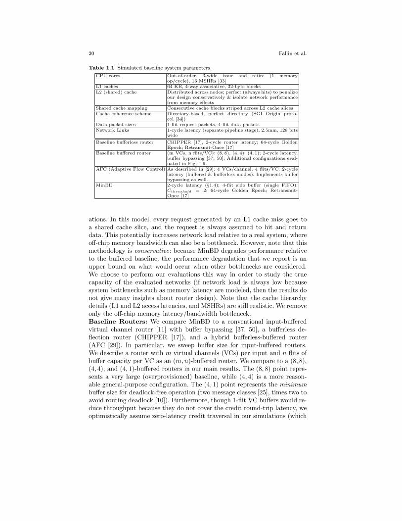
Table 1.1 Simulated baseline system parameters.
CPU cores Out-of-order, 3-wide issue and retire (1 memoryop/cycle), 16 MSHRs [33]
L1 caches 64 KB, 4-way associative, 32-byte blocksL2 (shared) cache Distributed across nodes; perfect (always hits) to penalize
our design conservatively & isolate network performancefrom memory effects
Shared cache mapping Consecutive cache blocks striped across L2 cache slicesCache coherence scheme Directory-based, perfect directory (SGI Origin proto-
col [34])Data packet sizes 1-flit request packets, 4-flit data packetsNetwork Links 1-cycle latency (separate pipeline stage), 2.5mm, 128 bits
wide
Baseline bufferless router CHIPPER [17], 2-cycle router latency; 64-cycle GoldenEpoch; Retransmit-Once [17]
Baseline buffered router (m VCs, n flits/VC): (8, 8), (4, 4), (4, 1); 2-cycle latency,buffer bypassing [37, 50]; Additional configurations eval-uated in Fig. 1.9.
AFC (Adaptive Flow Control) As described in [29]: 4 VCs/channel, 4 flits/VC. 2-cyclelatency (buffered & bufferless modes). Implements bufferbypassing as well.
MinBD 2-cycle latency (§1.4); 4-flit side buffer (single FIFO);Cthreshold = 2; 64-cycle Golden Epoch; Retransmit-Once [17]
ations. In this model, every request generated by an L1 cache miss goes toa shared cache slice, and the request is always assumed to hit and returndata. This potentially increases network load relative to a real system, whereoff-chip memory bandwidth can also be a bottleneck. However, note that thismethodology is conservative: because MinBD degrades performance relativeto the buffered baseline, the performance degradation that we report is anupper bound on what would occur when other bottlenecks are considered.We choose to perform our evaluations this way in order to study the truecapacity of the evaluated networks (if network load is always low becausesystem bottlenecks such as memory latency are modeled, then the results donot give many insights about router design). Note that the cache hierarchydetails (L1 and L2 access latencies, and MSHRs) are still realistic. We removeonly the off-chip memory latency/bandwidth bottleneck.Baseline Routers: We compare MinBD to a conventional input-bufferedvirtual channel router [11] with buffer bypassing [37, 50], a bufferless de-flection router (CHIPPER [17]), and a hybrid bufferless-buffered router(AFC [29]). In particular, we sweep buffer size for input-buffered routers.We describe a router with m virtual channels (VCs) per input and n flits ofbuffer capacity per VC as an (m,n)-buffered router. We compare to a (8, 8),(4, 4), and (4, 1)-buffered routers in our main results. The (8, 8) point repre-sents a very large (overprovisioned) baseline, while (4, 4) is a more reason-able general-purpose configuration. The (4, 1) point represents the minimumbuffer size for deadlock-free operation (two message classes [25], times two toavoid routing deadlock [10]). Furthermore, though 1-flit VC buffers would re-duce throughput because they do not cover the credit round-trip latency, weoptimistically assume zero-latency credit traversal in our simulations (which

1 Bufferless and Minimally-Buffered Deflection Routing 21
benefits the baseline design, hence is conservative for our claims). Finally,we simulate smaller (non-deadlock-free) designs with 1 and 2 VCs per inputfor our power-performance tradeoff evaluation in §1.6.2 (Fig. 1.9), solely forcompleteness (we were able to avoid deadlock at moderate loads and withfinite simulation length for these runs).Application Workloads: We use SPEC CPU2006 [45] benchmarks (26 ap-plications7) to construct 75 multiprogrammed workloads (which consist ofmany single-threaded benchmark instances that run independently). Eachworkload consists of 16 or 64 randomly-selected applications which arerandomly mapped onto the mesh. Workloads are categorized by averagenetwork injection rate in the baseline (4, 4)-buffered system (measured inflits/cycle/node). For 4x4 workloads, these injection rate categories are(0, 0.15), (0.15, 0.3), (0.3, 0.4), (0.4, 0.5), and > 0.5; for 8x8 workloads,(0, 0.05), (0.05, 0.15), (0.15, 0.25), and > 0.25 (an 8x8 mesh saturates at alower load than a 4x4 mesh, due to limited bisection bandwidth). Each cat-egory contains 15 workloads.Synthetic-Traffic Workloads: To show robustness under various traf-fic patterns, we evaluate 4x4 and 8x8 networks with uniform-random, bit-complement, and transpose synthetic traffic [11] in addition to applicationworkloads. For each pattern, network injection rate is swept from zero tonetwork saturation.Performance Metrics: To measure system performance, we use the well-
known Weighted Speedup metric [44]: WS =∑N
i=1IPCshared
i
IPCalonei
. All IPCalonei
values are measured on the baseline bufferless network. Weighted speedupcorrelates to system throughput [16] and is thus a good general metric formultiprogrammed workloads.Power Modeling: We use a modified and improved version of ORION2.0 [49] (configured for 65nm), as developed by Grot et al. [24], as well asVerilog models synthesized with a commercial 65nm design library. We useVerilog models of router control logic, and add datapath area and power usingORION models for crossbars, buffers, links, and pipeline registers. CHIPPERand MinBD do not use a conventional crossbar, instead decoupling the cross-bar into a permutation network, which we model using muxes. We rely onORION’s modeling for the baseline input-buffered router’s control logic (e.g.,arbitration). This hybrid synthesis / ORION approach models each portionof the router in a way that captures its key limitations. The control logicis logic- rather than wiring-dominated, and its arbitration paths determinethe critical path; hence, standard-cell synthesis will model area, power andtiming of MinBD and CHIPPER control logic with reasonable accuracy. Therouter datapath is wiring-dominated and relies on heavily-optimized compo-nents with custom layouts such as large crossbars and wide muxes, pipelineregisters and memories. ORION explicitly models such router components.
7 410.bwaves, 416.gamess and 434.zeusmp were excluded because we were not able to
collect representative traces from these applications.

22 Fallin et al.
We report energy efficiency as performance-per-watt, computed as weightedspeedup divided by average network power.
1.6 Evaluation
In this section, we evaluate MinBD against a bufferless deflection router [17]and an input-buffered router with buffer bypassing [37, 50], as well as ahybrid of these two, AFC [29], and demonstrate that by using a combinationof deflection routing and buffering, MinBD achieves performance competitivewith the conventional input-buffered router (and higher than the bufferlessdeflection router), with a smaller buffering requirement, and better energyefficiency than all prior designs.
1.6.1 Application Performance
Fig. 1.8 (top pane) shows application performance as weighted speedup for4x4 (16-node) and 8x8 (64-node) CMP systems. The plots show average re-sults for each workload category, as described in §1.5, as well as overall av-erage results. Each bar group shows the performance of three input-bufferedrouters: 8 VCs with 8 flits/VC, 4 VCs with 4 flits/VC, and 4 VCs with1 flit/VC. Next is CHIPPER, the bufferless deflection router, followed byAFC [29], a coarse-grained hybrid router that switches between a bufferlessand a buffered mode. MinBD is shown last in each bar group. We makeseveral observations:
1. MinBD improves performance relative to the bufferless deflection routerby 2.7% (4.9%) in the 4x4 (8x8) network over all workloads, and 8.1% (15.2%)in the highest-intensity category. Its performance is within 2.7% (3.9%) ofthe (4, 4) input-buffered router, which is a reasonably-provisioned baseline,and within 3.1% (4.2%) of the (8, 8) input-buffered router, which has large,power-hungry buffers. Hence, adding a side buffer allows a deflection routerto obtain significant performance improvement, and the router becomes morecompetitive with a conventional buffered design.
2. Relative to the 4-VC, 1-flit/VC input-buffered router (third bar), whichis the smallest deadlock-free (i.e., correct) design, MinBD performs nearly thesame despite having less buffer space (4 flits in MinBD vs. 16 flits in (4, 1)-buffered). Hence, buffering only a portion of traffic (i.e., flits that would havebeen deflected) makes more efficient use of buffer space.
3. AFC, the hybrid bufferless/buffered router which switches modes atthe router granularity, performs essentially the same as the 4-VC, 4-flit/VCinput-buffered router, because it is able to use its input buffers when load

1 Bufferless and Minimally-Buffered Deflection Routing 23
0
4
8
12
16
Wei
ghte
dS
pee
dup
4x4
0.00 - 0.15 0.15 - 0.30 0.30 - 0.40 0.40 - 0.50 > 0.50 AVG
Buffered (8,8)Buffered (4,4)Buffered (4,1)
Pure Bufferless (CHIPPER)AFC (4,4)MinBD-4
0
1
2
3
4
5
Bu
f(8
,8)
Bu
f(4
,4)
Bu
f(4
,1)
CH
IPP
ER
AF
C(4
,4)
Min
BD
-4
Bu
f(8
,8)
Bu
f(4
,4)
Bu
f(4
,1)
CH
IPP
ER
AF
C(4
,4)
Min
BD
-4
Bu
f(8
,8)
Bu
f(4
,4)
Bu
f(4
,1)
CH
IPP
ER
AF
C(4
,4)
Min
BD
-4
Bu
f(8
,8)
Bu
f(4
,4)
Bu
f(4
,1)
CH
IPP
ER
AF
C(4
,4)
Min
BD
-4
Bu
f(8
,8)
Bu
f(4
,4)
Bu
f(4
,1)
CH
IPP
ER
AF
C(4
,4)
Min
BD
-4
Bu
f(8
,8)
Bu
f(4
,4)
Bu
f(4
,1)
CH
IPP
ER
AF
C(4
,4)
Min
BD
-4
Pow
er (
W) static buffer
static linkstatic other
dynamic bufferdynamic link
dynamic other
0 5
10 15 20
0.00 - 0.15
0.15 - 0.30
0.30 - 0.40
0.40 - 0.50
> 0.50
AV
GEner
gy E
ffic
iency
(Per
f/W
)
Network Intensity
0
16
32
48
64
Wei
ghte
dS
pee
dup
8x80.00 - 0.05 0.05 - 0.15 0.15 - 0.25 > 0.25 AVG
0
4
8
12
16
20
Bu
f(8
,8)
Bu
f(4
,4)
Bu
f(4
,1)
CH
IPP
ER
AF
C(4
,4)
Min
BD
-4
Bu
f(8
,8)
Bu
f(4
,4)
Bu
f(4
,1)
CH
IPP
ER
AF
C(4
,4)
Min
BD
-4
Bu
f(8
,8)
Bu
f(4
,4)
Bu
f(4
,1)
CH
IPP
ER
AF
C(4
,4)
Min
BD
-4
Bu
f(8
,8)
Bu
f(4
,4)
Bu
f(4
,1)
CH
IPP
ER
AF
C(4
,4)
Min
BD
-4
Bu
f(8
,8)
Bu
f(4
,4)
Bu
f(4
,1)
CH
IPP
ER
AF
C(4
,4)
Min
BD
-4
Pow
er (
W) static buffer
static linkstatic other
dynamic bufferdynamic link
dynamic other
0 5
10 15 20 25
0.0 - 0.05
0.05 - 0.15
0.15 - 0.25
> 0.25
AV
GEner
gy E
ffic
iency
(Per
f/W
)
Network Intensity
Fig. 1.8 Performance (weighted speedup), network power, and energy efficiency (perfor-
mance per watt) in 16 (4x4) and 64 (8x8)-node CMP systems.

24 Fallin et al.
increases. However, as we will see, this performance comes at an efficiencycost relative to our hybrid design.
1.6.2 Network Power and Energy Efficiency
Network Power: Fig. 1.8 (middle pane) shows average total network power,split by component and type (static/dynamic), for 4x4 and 8x8 networksacross the same workloads. Note that static power is shown in the bottomportion of each bar, and dynamic power in the top portion. Each is split intobuffer power, link power, and other power (which is dominated by datap-ath components, e.g., the crossbar and pipeline registers). We make severalobservations:
1. Buffer power is a large part of total network power in the input-bufferedrouters that have reasonable buffer sizes, i.e., (4, 4) and (8, 8) (VCs, flits/VC),even with empty-buffer bypassing, largely because static buffer power (bot-tom bar segment) is significant. Removing large input buffers reduces staticpower in MinBD as well as the purely-bufferless baseline, CHIPPER.8 Be-cause of this reduction, MinBD’s total network power never exceeds that ofthe input-buffered baselines, except in the highest-load category in an 8x8-mesh (by 4.7%).
2. Dynamic power is larger in the baseline deflection-based router, CHIP-PER, than in input-buffered routers: CHIPPER has 31.8% (41.1%) higherdynamic power than the (4, 4)-buffered router in the 4x4 (8x8) networks inthe highest-load category. This is because bufferless deflection-based rout-ing requires more network hops, especially at high load. However, in a 4x4network, MinBD consumes less dynamic power (by 8.0%) than the (4, 4)-buffered baseline in the highest-load category because reduced deflection rate(by 58%) makes this problem relatively less significant, and allows savingsin buffer dynamic energy and a simplified datapath to come out. In an 8x8network, MinBD’s dynamic power is only 3.2% higher.
3. MinBD and CHIPPER, which use a permutation network-based dat-apath rather than a full 5x5 crossbar, reduce datapath static power (whichdominates the “static other” category) by 31.0%: the decoupled permuta-tion network arrangement has less area, in exchange for partial permutabil-ity (which causes some deflections). Input-buffered routers and AFC requirea full crossbar because they cannot deflect flits when performing bufferedrouting (partial permutability in a non-deflecting router would significantlycomplicate switch arbitration, because each output arbiter’s choice would belimited by which other flits are traversing the router).
8 Note that network power in the buffered designs takes buffer bypassing into account,
which reduces these baselines’ dynamic buffer power. The (4, 4)-buffered router bypasses73.7% (83.4%) of flits in 4x4 (8x8) networks. Without buffer bypassing, this router has
7.1% (6.8%) higher network power, and 6.6% (6.4%) worse energy-efficiency.

1 Bufferless and Minimally-Buffered Deflection Routing 25
4. AFC, the coarse-grained hybrid, has nearly the same network power asthe (4, 4) buffered router at high load: 0.6% (5.7%) less in 4x4 (8x8). This isbecause its buffers are enabled most of the time. At low load, when it canpower-gate its buffers frequently, its network power reduces. However, AFC’snetwork power is still higher than the pure bufferless router (CHIPPER)or MinBD because (i) it still spends some time in its buffered mode, and(ii) its datapath power is higher, as described above. On average, AFC stillconsumes 36.8% (18.1%) more network power than CHIPPER, and 33.5%(33.0%) more than MinBD, in the lowest-load category.Energy efficiency: Fig. 1.8 (bottom pane) shows energy efficiency. We maketwo key observations:
1. MinBD has the highest energy efficiency of any evaluated design: onaverage in 4x4 (8x8) networks, 42.6% (33.8%) better than the reasonably-provisioned (4, 4) input-buffered design. MinBD has 15.9% (8.7%) betterenergy-efficiency than the most energy-efficient prior design, the (4, 1)-bufferedrouter.
2. At the highest network load, MinBD becomes less energy-efficient com-pared to at lower load, and its efficiency degrades at a higher rate than theinput-buffered routers with large buffers (because of deflections). However,its per-category energy-efficiency is still better than all baseline designs, withtwo exceptions. In the highest-load category (near saturation) in an 8x8-mesh, MinBD has nearly the same efficiency as the (4, 1)-buffered router(but, note that MinBD is much more efficient than this baseline router atlower loads). In the lowest-load category in a 4x4 mesh, the purely-bufferlessrouter CHIPPER is slightly more energy-efficient (but, note that CHIPPER’sperformance and efficiency degrade quickly at high loads).
8
9
10
11
12
13
14
15
16
1 1.2 1.4 1.6 1.8 2 2.2 2.4 2.6
Wei
ghte
d S
pee
dup
Power (W)
Better E
fficiency
Worse
Effi
ciency
MinBD
CHIPPERAFC
Buffered1,11,22,1
1,4 1,8
2,24,2
2,8
2,4 4,44,1
8,84,8 8,2 8,4
Fig. 1.9 Power (X) vs. application performance (Y) in 4x4 networks. The line representsall points with equivalent performance-per-watt to MinBD.
We conclude that, by achieving competitive performance with the bufferedbaseline, and making more efficient use of a much smaller buffer capacity(hence reducing buffer power and total network power), MinBD provides bet-ter energy efficiency than prior designs. To summarize this result, we show a2D plot of power and application performance in Fig. 1.9 for 4x4 networks,

26 Fallin et al.
and a wider range of buffered router designs, as well as MinBD and CHIP-PER. (Recall from §1.5 that several of the baseline input-buffered designs arenot deadlock free (too few VCs) or have a buffer depth that does not covercredit round-trip latency, but we evaluate them anyway for completeness.)In this plot, with power on the X axis and application performance on the Yaxis, a line through the origin represents a fixed performance-per-watt ratio(the slope of the line). This equal-efficiency line is shown for MinBD. Pointsabove the line have better efficiency than MinBD, and points below haveworse efficiency. As shown, MinBD presents the best energy efficiency amongall evaluated routers. The trend in an 8x8 network (not shown for space) issimilar (see technical report [18]).
1.6.3 Performance Breakdown
To understand the observed performance gain in more detail, we now breakdown performance by each component of MinBD. Fig. 1.10 shows perfor-mance (for 4x4 networks) averaged across all workloads for eight deflectionsystems, which constitute all possible combinations of MinBD’s mechanismsadded to the baseline (CHIPPER) router: dual-width ejection (D), silver-flit prioritization (S), and the side buffer (B), shown with the same threeinput-buffered configurations as before. The eighth bar (D+S+B), whichrepresents all three mechanisms added to the baseline deflection network,represents MinBD. Table 1.2 shows deflection rate for the same set of sys-tems.
Fig. 1.10 Breakdown of performance gains for each mechanism in MinBD.
Table 1.2 Average deflection rates for deflection-based routers.
Baseline(CHIPPER)
D S B D+S D+B S+B D+S+B(MinBD)
0.28 0.22 0.27 0.17 0.22 0.11 0.16 0.10

1 Bufferless and Minimally-Buffered Deflection Routing 27
Table 1.3 Normalized router area and critical path for bufferless and buffered baselines,
compared to MinBD.
Router Design CHIPPER MinBD Buffered (8, 8) Buffered (4, 4) Buffered (4, 1)
Normalized Area 1.00 1.03 2.06 1.69 1.60
Normalized Critical
Path Length
1.00 1.07 0.99 0.99 0.99
We draw three main conclusions:1. All mechanisms individually contribute to performance and reduce de-
flection rate. Dual ejection (D) increases performance by 3.7% over baselineCHIPPER.9 Adding silver-flit prioritization (D+S) increases performance by0.7% over dual-ejection alone. Adding a side buffer to the other two mecha-nisms (D+S+B) increases performance by 2.0% on average.
2. Adding a side buffer by itself (B) is not sufficient to attain the per-formance that MinBD achieves. In fact, when only the side buffer is added,performance drops by 4.3% relative to baseline CHIPPER. The degradationoccurs primarily because the increased in-network throughput (enabled bya reduced deflection rate) in the network with side buffers places more ejec-tion pressure on nodes, which exacerbates the ejection bottleneck that weobserved in §1.4.1. This performance reduction comes despite a reduced de-flection rate: even though flits are not deflected as frequently, they must stillbe removed from the network efficiently for performance to increase.
3. Adding dual ejection to the side buffered system (D+B) to addressthe ejection bottleneck increases performance to 5.8% above baseline. Silver-flit prioritization in addition to this configuration point yields the MinBDrouter (eighth bar), which attains 6.6% performance above baseline (2.7%above dual-ejection alone) on average for all workload intensities. Overall,deflection rate reduces by 64% from baseline CHIPPER to MinBD (and 54%from CHIPPER with dual-ejection (D) to MinBD, as shown in our primaryresults).
1.6.4 Synthetic Traffic Performance
We study the network-level performance of MinBD and baseline designs byapplying synthetic traffic patterns: uniform random, bit-complement, andtranspose [11]. Fig. 1.11 shows latency curves with injection rate swept fromzero to saturation for the bufferless deflection router, MinBD, and the (4, 1)and (8, 8) input-buffered router (other input-buffered routers are omitted forclarity; these are the smallest and largest evaluated input-buffered routers,to show lower and upper bounds). Latency curves are shown for uniform
9 The main results presented in Fig. 1.8 use this data point (with dual ejection) in order
to make a fair (same external router interface) comparison.

28 Fallin et al.
5
10
15
20
25
0 0.2 0.4 0.6
Lat
ency
4x4
Uniform Random
CHIPPERMinBD
Buffered (4,1)Buffered (8,8)
5
10
15
20
25
0 0.1 0.2 0.3 0.4 0.5
Bit Complement
5
10
15
20
25
0 0.1 0.2 0.3 0.4
Lat
ency
Transpose
5
10
15
20
25
0 0.1 0.2 0.3 0.4 0.5
Hotspot
5
10
15
20
25
0 0.1 0.2
Lat
ency
8x8
Uniform Random
5
10
15
20
25
0 0.05 0.1 0.15 0.2
Bit Complement
5
10
15
20
25
0 0.05 0.1 0.15
Lat
ency
Injection Rate
Transpose
5
10
15
20
25
0 0.05 0.1 0.15 0.2
Injection Rate
Hotspot
Fig. 1.11 Synthetic traffic evaluations for MinBD, CHIPPER and input-buffered routers(with small and large input buffers), in 4x4 and 8x8 meshes.

1 Bufferless and Minimally-Buffered Deflection Routing 29
random, bit complement, transpose, and hotspot patterns. In the “hotspot”pattern, nodes send requests to a single node at the center of the mesh with20% probability and to random locations otherwise. (Under a 100% hotspotpattern, the performance of all designs converges because the receiving node’sejection bandwidth is the bottleneck. A 20% skewed hotspot pattern is morerealistic because it tests the network’s capacity to handle unbalanced load.)
Under uniform random traffic (which most closely resembles our multi-programmed application workloads with striped data mapping), MinBD per-forms better than the bufferless baseline, with a higher saturation point.MinBD has a lower network saturation point than the input-buffered net-work with large input buffers, but very similar saturation point to the small(4, 1) input-buffered router, as our earlier results indicated. We conclude thatwith only 4 flits of buffering per router, MinBD closes nearly half of the gapin network saturation throughput between the bufferless router (CHIPPER)and the largest input-buffered router (with 256 flits of total buffer space),and performs similarly to a smaller input-buffered router with 16 flits oftotal buffer space.
In addition, non-uniform traffic patterns demonstrate the robustness andadaptivity of deflection routing: in particular, the transpose traffic patterndemonstrates a lower saturation point in the input-buffered router than ei-ther deflection-based router (MinBD or CHIPPER). This advantage occursbecause deflection routing is adaptive (a flit’s path can change based on net-work conditions). Deflections spread traffic away from hotspots and balanceload in unbalanced traffic patterns. While adaptive routing is also possiblein input-buffered routers, it is more complex because it requires the routerto track network load or congestion (locally or globally) and make decisionsaccordingly. In contrast, deflection routing provides adaptivity by virtue ofits ordinary operation.
1.6.5 Sensitivity to Parameters
Side Buffer Size: As side buffer size is varied from 1 to 64 flits, meanweighted speedup (application performance) changes only 0.2% on averageacross all workloads (0.9% in the highest-intensity category) in 4x4 networks.We conclude that the presence of the buffer (to buffer at least one deflectedflit) is more important than its size, because the average utilization of thebuffer is low. In a 4x4 MinBD network with 64-flit side buffers at saturation(61% injection rate, uniform random), the side buffer is empty 48% of thetime on average; 73% of the time, it contains 4 or fewer flits; 93% of thetime, 16 or fewer. These measurements suggest that a very small side buffercaptures most of the benefit. Furthermore, total network power increases by19% (average across all 4x4 workloads) when a 1-flit buffer per router is

30 Fallin et al.
increased to a 64-flit buffer per router. Hence, a larger buffer wastes powerwithout significant performance benefit.
We avoid a 1-flit side buffer because of the way the router is pipelined:such a single-flit buffer would either require for a flit to be able to enter, thenleave, the buffer in the same cycle (thus eliminating the independence of thetwo router pipeline stages), or else could sustain a throughput of one flit onlyevery two cycles. (For this sensitivity study, we optimistically assumed theformer option for the 1-flit case.) The 4-flit buffer we use avoids this pipeliningissue, while increasing network power by only 4% on average over the 1-flitbuffer.
Note that although the size we choose for the side buffer happens to bethe same as the 4-flit packet size which we use in our evaluations, this neednot be the case. In fact, because the side buffer holds deflected flits (notpackets) and deflection decisions occur at a per-flit granularity, it is unlikelythat the side buffer will hold more than one or two flits of a given packetat a particular time. Hence, unlike conventional input-buffered routers whichtypically size a buffer to hold a whole packet, MinBD’s side buffer can remainsmall even if packet size increases.Packet Size: Although we perform our evaluations using a 4-flit packet size,our conclusions are robust to packet size. In order to demonstrate this, we alsoevaluate MinBD, CHIPPER, and the (4, 4)- and (8, 8)-input-buffered routersin 4x4 and 8x8 networks using a data packet size of 8 flits. In a 4x4 (8x8)network, MinBD improves performance over CHIPPER by 17.1% (22.3%),achieving performance within 1.2% (8.1%) of the (4, 4)-input-buffered routerand within 5.5% (12.8%) of the (8, 8)-input-buffered router, while reducingaverage network power by 25.0% (18.1%) relative to CHIPPER, 16.0% (9.4%)relative to the (4, 4)-input-buffered router, and 40.3% (34.5%) relative to the(8, 8)-input-buffered router, respectively. MinBD remains the most energy-efficient design as packet size increases.
1.6.6 Hardware Cost: Router Area and Critical Path
We present normalized router area and critical path length in Table 1.3.Both metrics are normalized to the bufferless deflection router, CHIPPER,because it has the smallest area of all routers. MinBD adds only 3% areaoverhead with its small buffer. In both CHIPPER and MinBD, the datapathdominates the area. In contrast, the large-buffered baseline has 2.06x area,and the reasonably-provisioned buffered baseline has 1.69x area. Even thesmallest deadlock-free input-buffered baseline has 60% greater area than thebufferless design (55% greater than MinBD). In addition to reduced buffering,the reduction seen in CHIPPER and MinBD is partly due to the simplifieddatapath in place of the 5x5 crossbar (as also discussed in §1.6.2). Overall,MinBD reduces area relative to a conventional input-buffered router both

1 Bufferless and Minimally-Buffered Deflection Routing 31
by significantly reducing the required buffer size, and by using a more area-efficient datapath.
Table 1.3 also shows the normalized critical path length of each routerdesign, which could potentially determine the network operating frequency.MinBD increases critical path by 7% over the bufferless deflection router,which in turn has a critical path 1% longer than an input-buffered router. Inall cases, the critical path is through the flit arbitration logic (the permuta-tion network in MinBD and CHIPPER, or the arbiters in the input-bufferedrouter). MinBD increases critical path relative to CHIPPER by adding logicin the deflection-routing stage to pick a flit to buffer, if any. The buffer re-injection and redirection logic in the first pipeline stage (ejection/injection)does not impact the critical path because the permutation network pipelinestage has a longer critical path.
1.7 Related Work
To our knowledge, MinBD is the first NoC router design that combines de-flection routing with a small side buffer that reduces deflection rate. Otherrouters combine deflection routing with buffers, but do not achieve the effi-ciency of MinBD because they either continue to use input buffers for all flits(Chaos router) or switch all buffers on and off at a coarse granularity with aper-router mode switch (AFC), in contrast to MinBD’s fine-grained decisionto buffer or deflect each flit.Buffered NoCs that also use deflection: Several routers that primarilyoperate using buffers and flow control also use deflection routing as a sec-ondary mechanism under high load. The Chaos Router [32] deflects packetswhen a packet queue becomes full to probabilistically avoid livelock. However,all packets that pass through the router are buffered; in contrast, MinBD per-forms deflection routing first, and only buffers some flits that would have beendeflected. This key aspect of our design reduces buffering requirements andbuffer power. The Rotary Router [1] allows flits to leave the router’s innerring on a non-productive output port after circulating the ring enough times,in order to ensure forward progress. In this case, again, deflection is used asan escape mechanism to ensure probabilistic correctness, rather than as theprimary routing algorithm, and all packets must pass through the router’sbuffers.Other bufferless designs: Several prior works propose bufferless routerdesigns [17, 21, 26, 38, 48]. We have already extensively compared toCHIPPER [17], from which we borrow the deflection routing logic design.BLESS [38], another bufferless deflection network, uses a more complex de-flection routing algorithm. Later works showed BLESS to be difficult to imple-ment in hardware [17, 26, 37], thus we do not compare to it in this work. Otherbufferless networks drop rather than deflect flits upon contention [21, 26].

32 Fallin et al.
Some earlier large multiprocessor interconnects, such as those in HEP [42] andConnection Machine [27], also used deflection routing. The HEP router com-bined some buffer space with deflection routing [43]. However, these routers’details are not well-known, and their operating conditions (large off-chip net-works) are significantly different than those of modern NoCs.
More recently, Fallin et al. [19] applied deflection routing to a hierarchicalring topology, allowing most routers (those that lie within a ring) to be de-signed without any buffering or flow control, and using only small buffers totransfer between rings. The resulting design, HiRD, was shown to be moreenergy-efficient than the baseline hierarchical ring with more buffering. HiRDuses many of the same general ideas as MinBD to ensure forward progress,e.g., enforcing explicit forward-progress guarantees in the worst case withoutimpacting common-case complexity.Improving high-load performance in bufferless networks: Some workhas proposed congestion control to improve performance at high network loadin bufferless deflection networks [8, 39, 40]. Both works used source throttling:when network-intensive applications cause high network load which degradesperformance for other applications, these intensive applications are preventedfrom injecting network traffic some of the time. By reducing network load,source throttling reduces deflection rate and improves overall performanceand fairness. These congestion control techniques and others (e.g., [47]) areorthogonal to MinBD, and could improve MinBD’s performance further.Hybrid buffered-bufferless NoCs: AFC [29] combines a bufferless deflec-tion router based on BLESS [38] with input buffers, and switches betweenbufferless deflection routing and conventional input-buffered routing basedon network load at each router. While AFC has the performance of bufferedrouting in the highest-load case, with better energy efficiency in the low-loadcase (by power-gating buffers when not needed), it misses opportunity to im-prove efficiency because it switches buffers on at a coarse granularity. Whenan AFC router experiences high load, it performs a mode switch which takesseveral cycles in order to turn on its buffers. Then, it pays the buffering en-ergy penalty for every flit, whether or not it would have been deflected. It alsorequires buffers as large as the baseline input-buffered router design in orderto achieve equivalent high-load performance. As a result, its network poweris nearly as high as a conventional input-buffered router at high load, andit requires fine-grained power gating to achieve lower power at reduced net-work load. In addition, an AFC router has a larger area than a conventionalbuffered router, because it must include both buffers and buffered-routingcontrol logic as well as deflection-routing control logic. In contrast, MinBDdoes not need to include large buffers and the associated buffered-mode con-trol logic, instead using only a smaller side buffer. MinBD also removes thedependence on efficient buffer power-gating that AFC requires for energy-efficient operation at low loads. We quantitatively compared MinBD to AFCin §1.4 and demonstrated better energy efficiency at all network loads.
1 Bufferless and Minimally-Buffered Deflection Routing 33
Reducing cost of buffered routers: Empty buffer bypassing [50, 37] re-duces buffered router power by allowing flits to bypass input buffers whenempty. However, as our evaluations (which faithfully model the power re-ductions due to buffer bypassing) show, this scheme reduces power less thanour new router design: bypassing is only effective when buffers are empty,which happens more rarely as load increases. Furthermore, buffers continue toconsume static power, even when unused. Though both MinBD and empty-buffer-bypassed buffered routers avoid buffering significant traffic, MinBDfurther reduces router power by using much smaller buffers.
Kim [30] proposed a low-cost buffered router design in which a packetuses a buffer only when turning, not when traveling straight along one di-mension. Unlike our design, this prior work does not make use of deflection,but uses deterministic X-Y routing. Hence, it is not adaptive to differenttraffic patterns. Furthermore, its performance depends significantly on thesize of the turn-buffers. By using deflection, MinBD is less dependent onbuffer size to attain high performance, as we argued in §1.6.5. In addition,[30] implements a token-based injection starvation avoidance scheme whichrequires additional communication between routers, whereas MinBD requiresonly per-router control to ensure side buffer injection.
1.8 Conclusion
In this chapter, we introduced deflection routing and discussed two buffer-less deflection routers, BLESS [38] and CHIPPER [17]. We then describedMinBD [20], a minimally-buffered deflection router design. MinBD combinesdeflection routing with a small buffer, such that some network traffic thatwould have been deflected is placed in the buffer instead. Previous routerdesigns which use buffers typically place these buffers at the router inputs.In such a design, energy is expended to read and write the buffer for everyflit, and buffers must be large enough to efficiently handle all arriving traffic.In contrast to prior work, a MinBD router uses its buffer for only a fractionof network traffic, and hence makes more efficient use of a given buffer sizethan a conventional input-buffered router. Its average network power is alsogreatly reduced: relative to an input-buffered router, buffer power is muchlower, because buffers are smaller. Relative to a bufferless deflection router,dynamic power is lower, because deflection rate is reduced with the smallbuffer.
We evaluate MinBD against a comprehensive set of baseline router de-signs: three configurations of an input-buffered virtual-channel router [11], abufferless deflection router, CHIPPER [17], and a hybrid buffered-bufferlessrouter, AFC [29]. Our evaluations show that MinBD performs competitivelyand reduces network power: on average in a 4x4 network, MinBD performswithin 2.7% of the input-buffered design (a high-performance baseline) while
34 Fallin et al.
consuming 31.8% less total network power on average relative to this input-buffered router (and 13.4% less than the bufferless router, which performsworse than MinBD). Finally, MinBD has the best energy efficiency amongall routers which we evaluated. We conclude that a router design which aug-ments bufferless deflection routing with a small buffer to reduce deflectionrate is a compelling design point for energy-efficient, high-performance on-chip interconnect.
1.9 Future Work
We believe promising future research directions exist in bufferless and minimally-buffered deflection routers. One promising direction is to develop more effec-tive packet prioritization mechanisms that are applicable to such routers. Forexample, to improve system performance and fairness, mechanisms have beenproposed to perform packet prioritization in a manner that is aware of appli-cation characteristics [13] or packet latency slack [14]. Similarly, mechanismshave been proposed to provide quality of service to different applications inbuffered routers (e.g., [23, 24, 35]). Development of similar mechanisms forbufferless and minimally buffered routers is an open research problem. An-other promising direction is to develop techniques to increase the applicabilityof bufferless and minimally buffered deflection routing to different topologies,such as express cube topologies [22, 31] and hybrid and hierarchical topolo-gies [2, 15, 24]. Adaptation of bufferless and minimally-buffered deflectionrouting in a manner that guarantees correctness in different topologies, andthe evaluation of resulting techniques is an important area for future work.As a first step, our recent research [19] has developed new techniques to usedeflection routing in hierarchical ring topologies, with promising results thatshow that a minimally-buffered hierarchical ring design significantly improvessystem energy efficiency. We intend to explore these research directions in thefuture and hope that this chapter serves as an inspiration to other researchersas well.
Acknowledgments
We thank the anonymous reviewers of our conference papers CHIPPER [17]and MinBD [20] for their feedback. We gratefully acknowledge members of theSAFARI group and Michael Papamichael at CMU for feedback. Chris Fallinis currently supported by an NSF Graduate Research Fellowship (Grant No.0946825). Rachata Ausavarungnirun is currently supported by the Royal ThaiGovernment Scholarship. Greg Nazario and Xiangyao Yu were undergradu-ate research interns while this work was done. We acknowledge the generous

1 Bufferless and Minimally-Buffered Deflection Routing 35
support of our industrial partners, including AMD, HP Labs, IBM, Intel,NVIDIA, Oracle, Qualcomm, and Samsung. This research was partially sup-ported by grants from NSF (CAREER Award CCF-0953246, CCF-1147397and CCF-1212962). This article is a significantly extended and revised ver-sion of our previous conference papers that introduced CHIPPER [17] andMinBD [20].
References
[1] Abad, P., et al.: Rotary router: an efficient architecture for CMP inter-connection networks. ISCA-34 (2007)
[2] Balfour, J., Dally, W.J.: Design tradeoffs for tiled CMP on-chip networks.ICS (2006)
[3] Baran, P.: On distributed communications networks. IEEE Transactionson Communication Systems (1964)
[4] Borkar, S.: Thousand core chips: a technology perspective. DAC-44(2007)
[5] Borkar, S.: Future of interconnect fabric: a contrarian view. SLIP ’10(2010)
[6] Borkar, S.: NoCs: What’s the point? NSF Workshop on Emerging Tech.for Interconnects (WETI), Feb. 2012 (2012)
[7] Bose, P.: The power of communication: Trends, challenges (and account-ing issues). NSF WETI, Feb. 2012 (2012)
[8] Chang, K., et al.: HAT: Heterogeneous adaptive throttling for on-chipnetworks. SBAC-PAD (2012)
[9] Culler, D.E., et al.: Parallel Computer Architecture: A Hard-ware/Software Approach. Morgan Kaufmann (1999)
[10] Dally, W., Seitz, C.: Deadlock-free message routing in multiprocessorinterconnection networks. IEEE Trans. Comp. (1987)
[11] Dally, W., Towles, B.: Principles and Practices of Interconnection Net-works. Morgan Kaufmann (2004)
[12] Dally, W.J., Towles, B.: Route packets, not wires: On-chip interconnec-tion networks. DAC-38 (2001)
[13] Das, R., Mutlu, O., Moscibroda, T., Das, C.: Application-aware priori-tization mechanisms for on-chip networks. MICRO-42 (2009)
[14] Das, R., et al.: Aergia: exploiting packet latency slack in on-chip net-works. ISCA-37 (2010)
[15] Das, R., et al.: Design and evaluation of hierarchical on-chip networktopologies for next generation CMPs. HPCA-15 (2011)
[16] Eyerman, S., Eeckhout, L.: System-level performance metrics for multi-program workloads. IEEE Micro 28, 42–53 (2008)
[17] Fallin, C., et al.: CHIPPER: A low-complexity bufferless deflectionrouter. HPCA-17 (2011)

36 Fallin et al.
[18] Fallin, C., et al.: MinBD: Minimally-buffered deflection routing forenergy-efficient interconnect. SAFARI technical report TR-2011-008:http://safari.ece.cmu.edu/tr.html (2011)
[19] Fallin, C., et al.: HiRD: A low-complexity, energy-efficient hierarchi-cal ring interconnect. SAFARI technical report TR-2012-004: http:
//safari.ece.cmu.edu/tr.html (2012)[20] Fallin, C., et al.: MinBD: Minimally-buffered deflection routing for
energy-efficient interconnect. NOCS-4 (2012)[21] Gomez, C., et al.: Reducing packet dropping in a bufferless noc. Euro-
Par-14 (2008)[22] Grot, B., Hestness, J., Keckler, S., Mutlu, O.: Express cube topologies
for on-chip interconnects. HPCA-15 (2009)[23] Grot, B., Keckler, S., Mutlu, O.: Preemptive virtual clock: A flexible,
efficient, and cost-effective qos scheme for networks-on-chip. MICRO-42(2009)
[24] Grot, B., et al.: Kilo-NOC: A heterogeneous network-on-chip architec-ture for scalability and service guarantees. ISCA-38 (2011)
[25] Hansson, A., et al.: Avoiding message-dependent deadlock in network-based systems-on-chip. VLSI Design (2007)
[26] Hayenga, M., et al.: SCARAB: A single cycle adaptive routing andbufferless network. MICRO-42 (2009)
[27] Hillis, W.: The Connection Machine. MIT Press (1989)[28] Hoskote, Y., et al.: A 5-GHz mesh interconnect for a teraflops processor.
IEEE Micro (2007)[29] Jafri, S.A.R., et al.: Adaptive flow control for robust performance and
energy. MICRO-43 (2010)[30] Kim, J.: Low-cost router microarchitecture for on-chip networks.
MICRO-42 (2009)[31] Kim, J., Balfour, J., Dally, W.: Flattened butterfly topology for on-chip
networks. MICRO-40 (2007)[32] Konstantinidou, S., Snyder, L.: Chaos router: architecture and perfor-
mance. ISCA-18 (1991)[33] Kroft, D.: Lockup-free instruction fetch/prefetch cache organization.
ISCA-8 (1981)[34] Laudon, J., Lenoski, D.: The SGI Origin: a ccNUMA highly scalable
server. ISCA-24 (1997)[35] Lee, J., Ng, M., Asanovic, K.: Globally-synchronized frames for guaran-
teed quality-of-service in on-chip networks. ISCA-35 (2008)[36] Luk, C.K., et al.: Pin: building customized program analysis tools with
dynamic instrumentation. PLDI (2005)[37] Michelogiannakis, G., et al.: Evaluating bufferless flow-control for on-
chip networks. NOCS (2010)[38] Moscibroda, T., Mutlu, O.: A case for bufferless routing in on-chip net-
works. ISCA-36 (2009)

1 Bufferless and Minimally-Buffered Deflection Routing 37
[39] Nychis, G., et al.: Next generation on-chip networks: What kind of con-gestion control do we need? Hotnets-IX (2010)
[40] Nychis, G., et al.: On-chip networks from a networking perspective: Con-gestion and scalability in many-core interconnects. SIGCOMM (2012)
[41] Patil, H., et al.: Pinpointing representative portions of large Intel Ita-nium programs with dynamic instrumentation. MICRO-37 (2004)
[42] Smith, B.: Architecture and applications of the HEP multiprocessor com-puter system. SPIE (1981)
[43] Smith, B.: Personal communication (2008)[44] Snavely, A., Tullsen, D.M.: Symbiotic jobscheduling for a simultaneous
multithreaded processor. ASPLOS-9 (2000)[45] Standard Performance Evaluation Corporation: SPEC CPU2006. http:
//www.spec.org/cpu2006 (2006)[46] Taylor, M., et al.: The Raw microprocessor: A computational fabric for
software circuits and general-purpose programs. IEEE Micro (2002)[47] Thottethodi, M., Lebeck, A., Mukherjee, S.: Self-tuned congestion con-
trol for multiprocessor networks. HPCA-7 (2001)[48] Tota, S., et al.: Implementation analysis of NoC: a MPSoC trace-driven
approach. GLSVLSI-16 (2006)[49] Wang, H., et al.: Orion: a power-performance simulator for interconnec-
tion networks. MICRO-35 (2002)[50] Wang, H., et al.: Power-driven design of router microarchitectures in
on-chip networks. MICRO-36 (2003)[51] Wentzlaff, D., et al.: On-chip interconnection architecture of the tile
processor. IEEE Micro 27(5), 15–31 (2007)