chapter 1: an introduction to smack...chapter 7: study case 1 - spark and cassandra figure 7-1....
TRANSCRIPT

Chapter 1: An Introduction to SMACK
Figure 1.1 The SMACK pipeline architecture
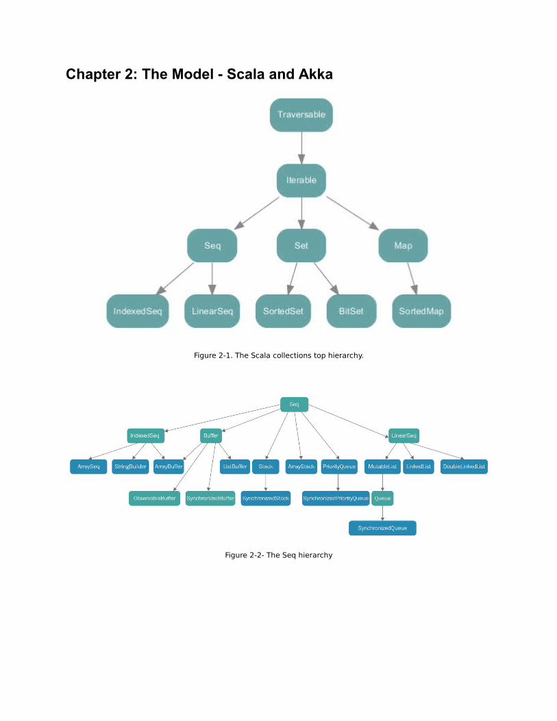
Chapter 2: The Model - Scala and Akka
Figure 2-1. The Scala collections top hierarchy.
Figure 2-2- The Seq hierarchy

Figure 2-3- The Map hierarchy
Figure 2-4- The Set hierarchy

Chapter 3: The Engine - Apache Spark
Figure 3-1 Apache Spark download page
Figure 3-2 Terminal window with Spark running

Figure 3-3 One driver program with three worker nodes

Figure 3-4. Distributed Spark application

Figure 3-5. Spark shell application web UI
Figure 3-6. Spark Streaming Operation
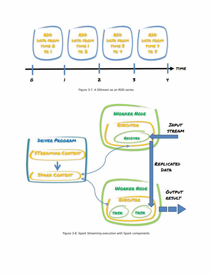
Figure 3-7. A DStream as an RDD series
Figure 3-8. Spark Streaming execution with Spark components

Figure 3-9. Windowed operations example

Chapter 4: The Storage - Apache Cassandra
Figure 4-1 CAP Brewer's theorem
Figure4-2: Column
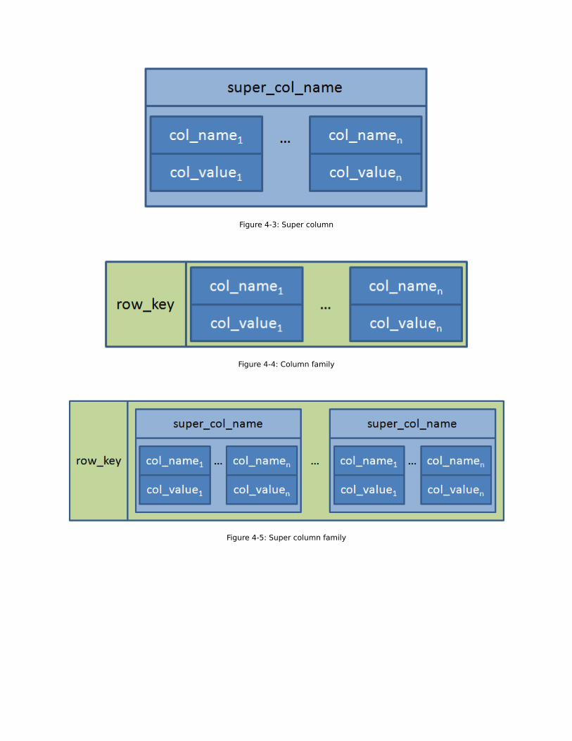
Figure 4-3: Super column
Figure 4-4: Column family
Figure 4-5: Super column family

Figure 4-6: Cluster with key spaces
Figure 4-7: Nodes within a cluster

Figure 4-8: DataStax OpsCenter
Figure 4-9: Microsoft Windows display services
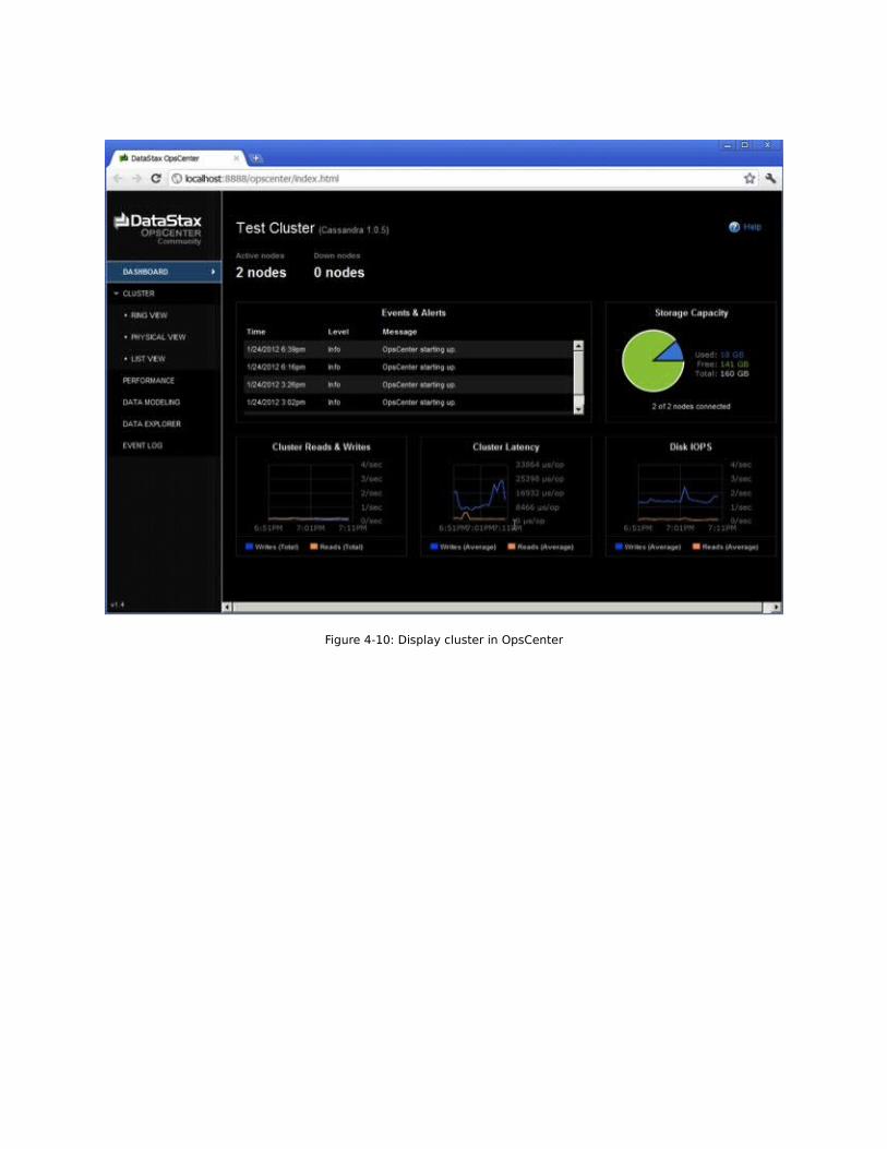
Figure 4-10: Display cluster in OpsCenter

Figure 4-11: Apache Cassandra cache

Chapter 5: The Broker - Apache Kafka
Figure 5-1. Apache Kafka typical scenario

Figure 5-2. Apache Kafka download page
Figure 5-3. Single node - single broker Kafka cluster example

Figure 5-4. Single node - multiple broker Kafka cluster example.
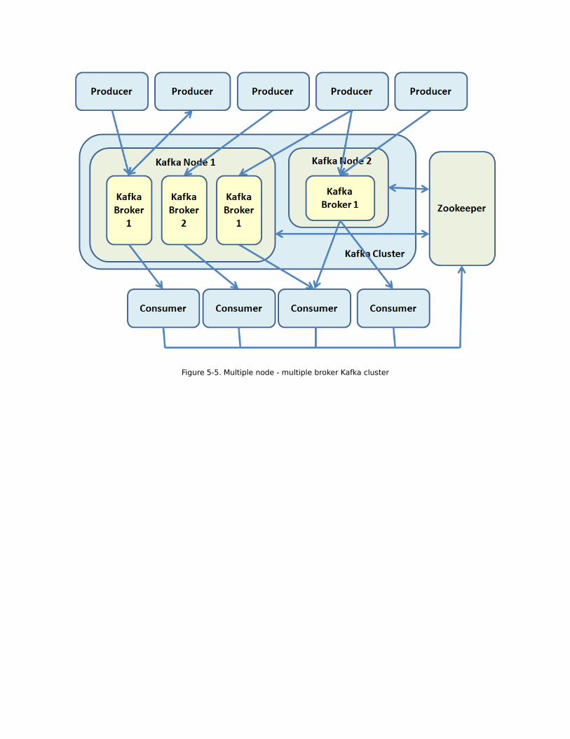
Figure 5-5. Multiple node - multiple broker Kafka cluster

Figure 5-6. A topic with 3 partitions

Chapter 7: Study Case 1 - Spark and Cassandra
Figure 7-1. Canonical Spark Cassandra cluster
Figure 7-2. Cassandra process and Spark worker one to one relationship

Figure 7-3. Step 1 - Define the business logic
Figure 7-4. Step 2 - Driver send the tasks to the Spark Master
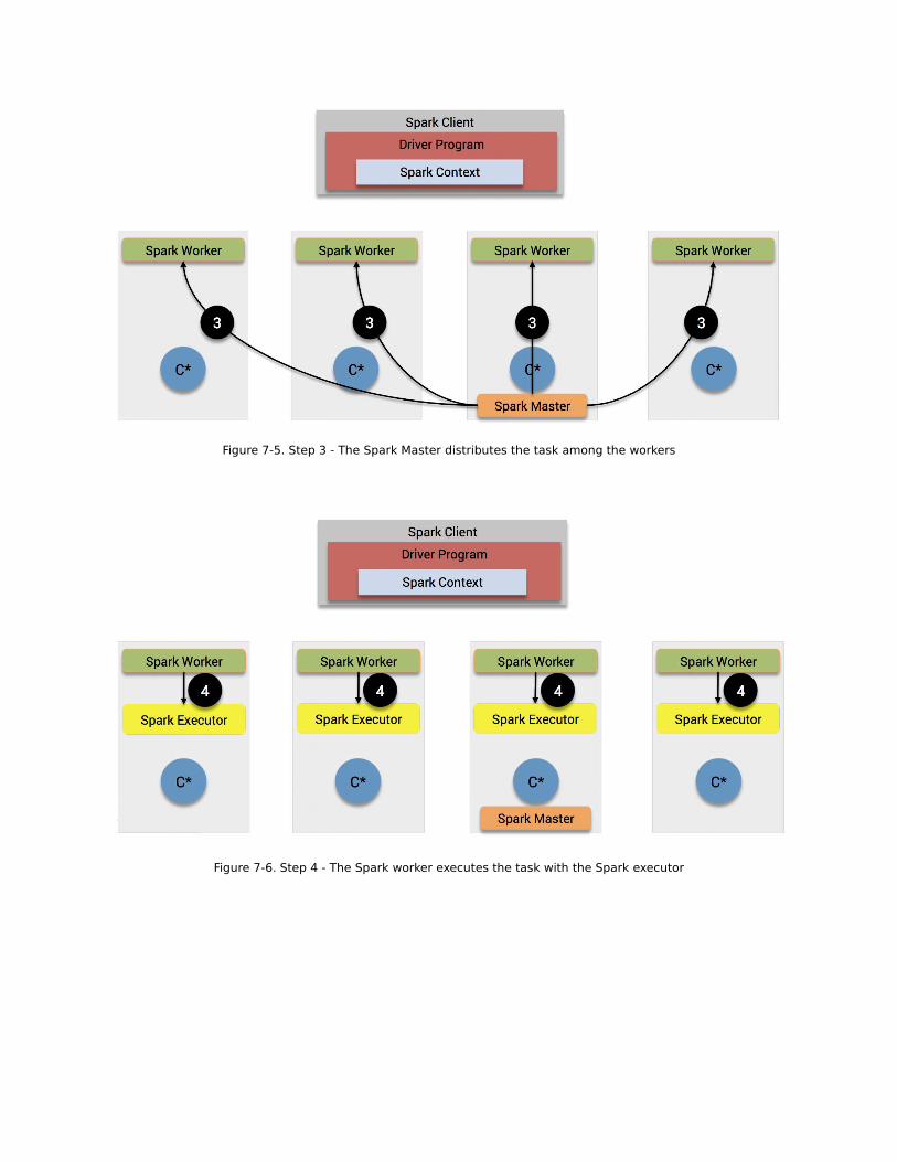
Figure 7-5. Step 3 - The Spark Master distributes the task among the workers
Figure 7-6. Step 4 - The Spark worker executes the task with the Spark executor

Figure 7-7. Step 5 - The Spark Executor executes the task with the Cassandra Process
Figure 7-8. Data Locality

Figure 7-9. Read data from Cassandra
Figure 7-10. Spark shuffle operations
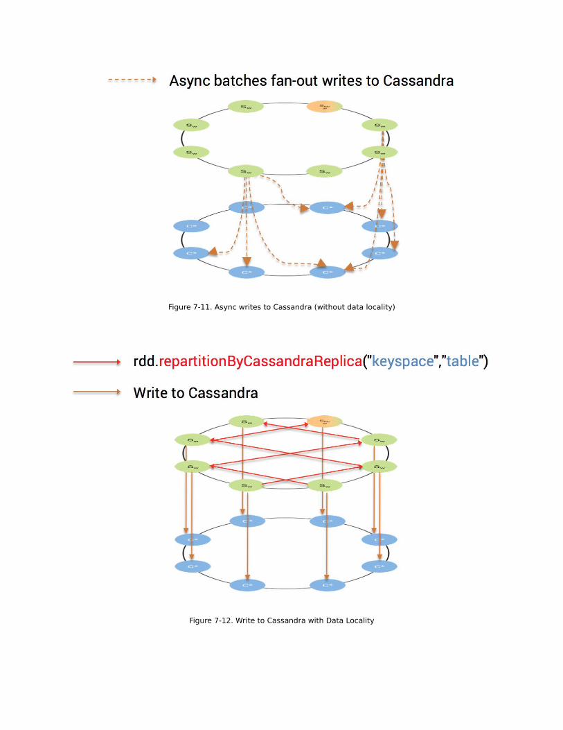
Figure 7-11. Async writes to Cassandra (without data locality)
Figure 7-12. Write to Cassandra with Data Locality
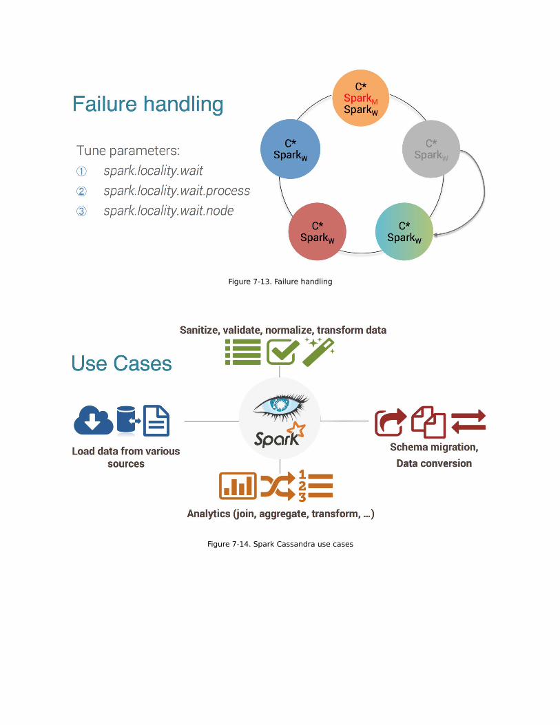
Figure 7-13. Failure handling
Figure 7-14. Spark Cassandra use cases

Chapter 8: Study Case 2 – Connectors
Figure 8-1. Twitter downloader actors

Chapter 9: Study Case 3 - Mesos and Docker
Figure 9.1. Comparison between a virtual machine and a Docker container

Figure 9.2. Containerization in Mesos