change-over inline filter rfld weld version up to 15000 l ... · 333 711040312 change-over inline...
TRANSCRIPT
333
E 7.
110.
4/03
.12
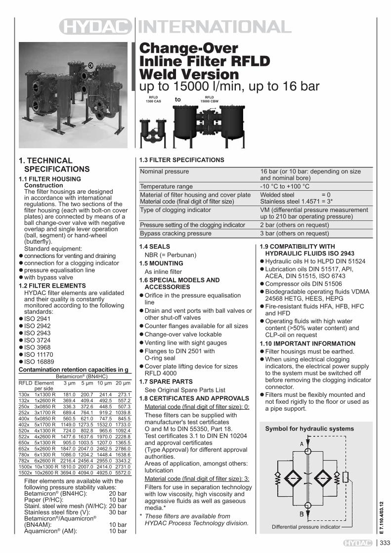
Change-Over Inline Filter RFLD Weld Versionup to 15000 l/min, up to 16 bar
1. TECHNiCAL SPECiFiCATiONS
1.1 FiLTER HOUSiNGConstruction The filter housings are designed in accordance with international regulations. The two sections of the filter housing (each with bolt-on cover plates) are connected by means of a ball change-over valve with negative overlap and single lever operation (ball, segment) or hand-wheel (butterfly).Standard equipment:
connections for venting and drainingconnection for a clogging indicatorpressure equalisation line with bypass valve1.2 FiLTER ELEMENTS
HYDAC filter elements are validated and their quality is constantly monitored according to the following standards:
ISO 2941ISO 2942 ISO 2943 ISO 3724ISO 3968 ISO 11170ISO 16889Contamination retention capacities in g Betamicron® (BN4HC)RFLD Element 3 µm 5 µm 10 µm 20 µm per side130x 1x1300 R 181.0 200.7 241.4 273.1132x 1x2600 R 369.4 409.4 492.5 557.2250x 3x0850 R 336.3 372.6 448.5 507.3252x 3x1700 R 689.4 764.1 919.2 1039.8400x 5x0850 R 560.5 621.0 747.5 845.5402x 5x1700 R 1149.0 1273.5 1532.0 1733.0520x 4x1300 R 724.0 802.8 965.6 1092.4522x 4x2600 R 1477.6 1637.6 1970.0 2228.8650x 5x1300 R 905.0 1003.5 1207.0 1365.5652x 5x2600 R 1847.0 2047.0 2462.5 2786.0780x 6x1300 R 1086.0 1204.2 1448.4 1638.6782x 6x2600 R 2216.4 2456.4 2955.0 3343.21500x 10x1300 R 1810.0 2007.0 2414.0 2731.01502x 10x2600 R 3694.0 4094.0 4925.0 5572.0
Filter elements are available with the following pressure stability values: Betamicron® (BN4HC): 20 bar Paper (P/HC): 10 bar Stainl. steel wire mesh (W/HC): 20 bar Stainless steel fibre (V): 30 bar Betamicron®/Aquamicron® (BN4AM): 10 bar Aquamicron® (AM): 10 bar
1.4 SEALSNBR (= Perbunan)
1.5 MOUNTiNGAs inline filter
1.6 SPECiAL MODELS AND ACCESSORiES
Orifice in the pressure equalisation line
Drain and vent ports with ball valves or other shut-off valves
Counter flanges available for all sizesChange-over valve lockableVenting line with sight gaugesFlanges to DIN 2501 with
O-ring sealCover plate lifting device for sizes
RFLD 40001.7 SPARE PARTS
See Original Spare Parts List1.8 CERTiFiCATES AND APPROVALS
Material code (final digit of filter size): 0:These filters can be supplied with manufacturer's test certificates O and M to DIN 55350, Part 18. Test certificates 3.1 to DIN EN 10204 and approval certificates (Type Approval) for different approval authorities. Areas of application, amongst others: lubricationMaterial code (final digit of filter size): 3:Filters for use in separation technology with low viscosity, high viscosity and aggressive fluids as well as gaseous media.*
* ThesefiltersareavailablefromHYDACProcessTechnologydivision.
1.9 COMPATiBiLiTY WiTH HYDRAULiC FLUiDS iSO 2943
Hydraulic oils H to HLPD DIN 51524Lubrication oils DIN 51517, API,
ACEA, DIN 51515, ISO 6743Compressor oils DIN 51506Biodegradable operating fluids VDMA
24568 HETG, HEES, HEPGFire-resistant fluids HFA, HFB, HFC
and HFDOperating fluids with high water
content (>50% water content) and CLP-oil on request
1.10 iMPORTANT iNFORMATiONFilter housings must be earthed.When using electrical clogging
indicators, the electrical power supply to the system must be switched off before removing the clogging indicatorconnector.
Filters must be flexibly mounted and not fixed rigidly to the floor or used as a pipe support.
1.3 FiLTER SPECiFiCATiONS
Nominal pressure 16 bar (or 10 bar: depending on size and nominal bore) Temperature range -10 °C to +100 °C Material of filter housing and cover plate Welded steel = 0 Material code (final digit of filter size) Stainless steel 1.4571 = 3* Type of clogging indicator VM (differential pressure measurement up to 210 bar operating pressure) Pressure setting of the clogging indicator 2 bar (others on request) Bypass cracking pressure 3 bar (others on request)
Symbol for hydraulic systems
E 7.
110.
4/03
.12
RFLD 1300 CAS
RFLD 15000 CBW
Differential pressure indicator
to

334
E 7.
110.
4/03
.12
RFLD BN/HC 1300 C A K 10 D 1 . X /-L24
Filter type RFLDFilter material of element BN/HC Betamicron® (BN4HC) P/HC Paper AM Aquamicron® V Stainless steel fibre W/HC Wire mesh BN/AM Betamicron®/Aquamicron®
Size of filter or element Welded steel: 1300, 1320, 2500, 2520, 4000, 4020, 5200, 5220, 6500, 6520, 7800, 7820, 15000, 15020 Stainl. steel 1.4571: 1303, 1323, 2503, 2523, 4003, 4023, 5203, 5223, 6503, 6523, 7803, 7823, 15003, 15023Operating pressure C = 16 bar (other operating pressures on request)Type of change-over A Ball All nominal bores except DN 200, 250, 300 B Segment Nominal bores DN 200, 250 C Butterfly Nominal bores DN 150, 200, 250, 300Type and size of port Steel, welded () - for lubrication applications; 1.4571 () - for emulsion applications (please contact Hydac Process Technology division)
Type Port Filter size13001303
13201323
2500250325202523
4000400340204023
5200520352205223
6500650365206523
7800780378207823
15000150031502015023
K SAE DN 40 L SAE DN 50 M SAE DN 65 S SAE/DIN DN 80 T SAE/DIN DN 100 U DIN DN 125 V DIN DN 150 W DIN DN 200 x DIN DN 250 Y DIN DN 300
Filtration rating in µm BN/HC, V: 3, 5, 10, 20 P/HC: 10, 20 AM: 40 W/HC: 25, 50, 100, 200 BN/AM: 3, 10Type of clogging indicator Y plastic blanking plug in indicator port A steel blanking plug in indicator port B visual for other clogging indicators, C electrical see brochure no. 7.050../.. D visual and electricalType code 1 Modification number X the latest version is always suppliedSupplementary details B. special cracking pressure (e.g. B1 = 1 bar) DE differential pressure measurement across element DH cover plate lifting device KB without bypass valve L... light with appropriate voltage (24V, 48V, 110V, 220V) only for clogging indicators LED 2 light emitting diodes up to 24 Volt type "D" OR O-ring groove on the DIN flange (inlet, outlet) to Rexroth standard AB22-04 RE sealing strip E on the flange (inlet, outlet): surface finish 3.6 µm - ball change-over, up to 150 nominal bore - segment change-over nominal bores CBV, CBW, CBX - butterfly change-over all nominal bores SB pressure equalisation line (SB2 = with 2mm orifice) V FPM seals
2. MODEL CODE (also order example)2.1 COMPLETE FiLTER
0850 R 010 BN4HC /-VSize 0850, 1300, 1700, 2600Type RFiltration rating in µm BN4HC, V: 003, 005, 010, 020 P/HC: 010, 020 AM: 040 W/HC: 025, 050, 100, 200 BN4AM: 003, 010Filter material BN4HC, V, W/HC, P/HC, BN4AM, AMSupplementary details V (for descriptions, see point 2.1)
2.2 REPLACEMENT ELEMENT
2.3 REPLACEMENT CLOGGiNG iNDiCATOR VM 2 D . X /-L24Type VM differential pressure measurement up to 210 bar operating pressurePressure setting 2 standard 2 bar, others on requestType of clogging indicator (see Point 2.1)Modification number X the latest version is always suppliedSupplementary details L..., LED, V (for descriptions, see point 2.1)
Other nominal bores, and ANSI flange version on request

335
E 7.
110.
4/03
.12
3. FiLTER CALCULATiON / SiZiNGThe total pressure drop of a filter at a certain flow rate Q is the sum of the housing ∆p and the element∆p and is calculated as follows:∆ptotal =∆phousing+∆pelement
∆phousing = (see Point 3.1)
∆pelement = Q • SK* • viscosity 1000 30 (*see point 3.2) For ease of calculation, our Filter Sizing Program is available on request free of charge.NEW: Sizing online at www.hydac.com
3.1 ∆p-Q HOUSiNG CURVES BASED ON iSO 3968The housing curves apply to mineral oil with a density of 0.86 kg/dm³ and a kinematic viscosity of 30mm²/s. In this case, the differential pressure changes proportionally to the density.
RFLD 1300, 1303
∆p [b
ar]
Q [l/min]
RFLD 1320, 1323
∆p [b
ar]
Q [l/min]
3.2 GRADiENT COEFFiCiENTS (SK) FOR FiLTER ELEMENTSThe gradient coefficients in mbar/(l/min) apply to mineral oils with a kinematic viscosity of 30 mm²/s. The pressure drop changes proportionally to the change in viscosity.
RFLD V W/HC 3 µm 5 µm 10 µm 20 µm –850 0.8 0.6 0.4 0.3 0.0631300 0.5 0.4 0.3 0.2 0.0451700 0.4 0.3 0.2 0.1 0.0322600 0.3 0.2 0.1 0.1 0.018
∆p [b
ar]
Q [l/min]
BN4HC: RFLD 1700
∆p [b
ar]
Q [l/min]
BN4HC: RFLD 850
∆p [b
ar]
Q [l/min]
BN4HC: RFLD 1300
∆p [b
ar]
Q [l/min]
BN4HC: RFLD 2600
RFLD 2500, 2503, 2520, 2523
∆p [b
ar]
Q [l/min]
RFLD 4000, 4003, 4020, 4023
∆p [b
ar]
Q [l/min]
RFLD 5200, 5203, 5220, 5223
∆p [b
ar]
Q [l/min]
RFLD 6500, 6503, 6520, 6523
∆p [b
ar]
Q [l/min]
RFLD 7800, 7803, 7820, 7823
∆p [b
ar]
Q [l/min]
RFLD 15000, 15003, 15020, 15023
∆p [b
ar]
Q [l/min]
without change-over valve with change-over valve

336
E 7.
110.
4/03
.12
Filter type Connection Change-over Volume of Weight [kg] including chamber [l] change-over valve and elements A (ball) B (segment) C (butterfly)1300, 1303 SAE DN 40 ball 2 x 22.0 105 SAE DN 50 ball 2 x 22.0 110 SAE DN 65 ball 2 x 22.0 115 SAE/DIN DN 80 ball 2 x 19.0 136 SAE/DIN DN 100 ball 2 x 19.0 150 1320, 1323 SAE DN 40 ball 2 x 37.0 138 SAE DN 50 ball 2 x 37.0 143 SAE DN 65 ball 2 x 37.0 148 SAE/DIN DN 80 ball 2 x 34.0 169 SAE/DIN DN 100 ball 2 x 34.0 183 DIN DN 125 ball 2 x 45.0 209 2500, 2503/ SAE DN 50 ball 2 x 34.0 / 2 x 54.0 144/174 2520, 2523 SAE DN 65 ball 2 x 34.0 / 2 x 54.0 149/179 SAE/DIN DN 80 ball 2 x 37.0 / 2 x 57.0 170/200 SAE/DIN DN 100 ball 2 x 39.0 / 2 x 59.0 184/214 DIN DN 125 ball, 2 x 40.0 / 2 x 60.0 208/238 DIN DN 150 ball, butterfly 2 x 45.0 / 2 x 65.0 262/292 287/3274000, 4003/ SAE/DIN DN 80 ball 2 x 63,0 / 2 x 96.0 210/270 4020, 4023 SAE/DIN DN 100 ball 2 x 63.0 / 2 x 96.0 222/283 DIN DN 125 ball 2 x 74.0 / 2 x 109.0 246/307 DIN DN 150 ball, butterfly 2 x 75.0 / 2 x 110.0 292/352 313/373 DIN DN 200 segment, butterfly 2 x 83.0 / 2 x 118.0 262/504 393/4535200, 5203/ SAE/DIN DN 80 ball 2 x 89.0 / 2 x 142.0 384/494 5220, 5223 SAE/DIN DN 100 ball 2 x 90.0 / 2 x 143.0 398/507 DIN DN 125 ball 2 x 104.0 / 2 x 157.0 422/532 DIN DN 150 ball, butterfly 2 x 106.0 / 2 x 159.0 476/586 503/614 DIN DN 200 segment, butterfly 2 x 110.0 / 2 x 162.0 646/756 596/706 DIN DN 250 segment, butterfly 2 x 128.0 / 2 x 180.0 890/1000 956/11186500, 6503/ SAE/DIN DN 100 ball 2 x 161.0 / 2 x 246.0 628/782 6520, 6523 DIN DN 125 ball 2 x 162.0 / 2 x 247.0 652/806 DIN DN 150 ball, butterfly 2 x 163.0 / 2 x 248.0 706/868 738/901 DIN DN 200 segment, butterfly 2 x 190.0 / 2 x 275.0 877/1039 826/988 DIN DN 250 segment, butterfly 2 x 194.0 / 2 x 279.0 1121/1282 956/11187800, 7803/ SAE/DIN DN 100 ball 2 x 161.0 / 2 x 246.0 636/798 7820, 7823 DIN DN 125 ball 2 x 162.0 / 2 x 247.0 660/822 DIN DN 150 ball, butterfly 2 x 163.0 / 2 x 248.0 714/884 746/917 DIN DN 200 segment, butterfly 2 x 190.0 / 2 x 275.0 885/1055 834/1004 DIN DN 250 segment, butterfly 2 x 194.0 / 2 x 279.0 1129/1298 964/113415000, 15003/ DIN DN 200 segment, butterfly 2 x 391.0 / 2 x 558.0 1210/1380 1143/1250 15020, 15023 DIN DN 250 segment, butterfly 2 x 397.0 / 2 x 564.0 1454/1623 1271/1379 DIN DN 300 butterfly 2 x 433.0 / 2 x 600.0 1487/1547
3.3 FiLTER SPECiFiCATiONS (TYPE OF CHANGE-OVER: A = BALL; B = SEGMENT; C = BUTTERFLY)

337
E 7.
110.
4/03
.12
4. DiMENSiONS4.1. WELDED FiLTER SERiES - BALL VERSiON RFLD 130x - 252x (CHANGE-OVER TYPE A)
Dimensions in mmType Flange b1 b2 b3 b4 d2 d3 h1 h2 h3 h4 h5 h6 h7
connection 1)
RFLD SAE DN 40 495 835 250 755 220 22 970/1410 205 335 95 460/900 92 500/940 1300/1320 SAE DN 50 506 846 250 766 220 22 970/1410 210 328 110 452/892 102 500/940 SAE DN 65 506 846 250 766 220 22 970/1410 210 328 110 452/892 167 500/940 SAE/DIN DN 80 530 870 250 790 220 22 970/1410 370 260 230 400/840 120 500/940 SAE/DIN DN 100 588 926 250 846 220 22 970/1410 375 266 250 374/814 130 500/940 RFLD 1320 DIN DN 125 603 943 250 863 220 22 1536 190 385 300 765 188 940RFLD SAE DN 50 548 908 250 312 273 22 940/1330 220 383 110 378/768 102 420/810 2500/2520 SAE DN 65 548 908 250 312 273 22 990/1380 220 383 230 280/670 167 420/810 SAE/DIN DN 80 572 932 250 312 273 22 990/1380 220 408 230 280/670 120 420/810 SAE/DIN DN 100 588 948 250 312 273 22 990/1380 220 408 250 260/650 130 420/810 DIN DN 125 589 949 250 312 273 22 1050/1440 220 438 300 240/630 188 420/810 DIN DN 150 641 1001 250 312 273 22 1050/1440 220 438 300 240/630 190 420/810
1) Flange connection to SAE J 518 C (standard pressure range 3000 psi) DIN flange connection to DIN 2501/1 for PN 16 from DN 125 and PN 25/40 up to DN 100 (sealing strip "D" or "E")
inlet
clogging indicator
outletdrain G1/2 contaminated side
lever for pressure equalisation line
vent G1/2
clogging indicator
drain G1 contaminated side
drain G 1 clean side
inlet
outlet
vent G1/2
lever for pressure equalisation line
RFLD 1300/1320 RFLD 2500/2520

338
E 7.
110.
4/03
.12
4.2. WELDED FiLTER SERiES - BALL VERSiON RFLD 400x - 782x (CHANGE-OVER TYPE A)
Dimensions in mmType Flange b1 b2 d1 d2 d3 h1 h2 h3 h4 h5 h6 h7 h8
connection 1)
RFLD SAE/DIN DN 80 688 1152 330 356 22 1080/1470 260 475 230 295/685 120 420/810 230 4000/4020 SAE/DIN DN 100 704 1164 330 356 22 1080/1470 260 475 250 275/665 130 420/810 230 DIN DN 125 723 1183 330 356 22 1170/1560 260 525 300 265/655 188 420/810 230 DIN DN 150 775 1240 330 356 22 1170/1560 260 525 300 265/655 190 420/810 230RFLD SAE/DIN DN 80 728 1244 380 406 22 1144/1584 250 465 230 371/811 120 500/940 255 5200/5220 SAE/DIN DN 100 744 1260 380 406 22 1144/1584 250 465 250 351/791 130 500/940 255 DIN DN 125 763 1275 380 406 22 1256/1696 250 525 300 351/791 188 500/940 255 DIN DN 150 815 1330 380 406 22 1256/1696 250 525 300 351/791 190 500/940 255RFLD SAE/DIN DN 100 1024 1644 480 508 22 1260/1700 260 540 250 390/830 130 500/940 310 6500/6520 DIN DN 125 863 1483 480 508 22 1260/1700 260 540 300 340/780 188 500/940 310 DIN DN 150 915 1535 480 508 22 1260/1700 260 540 300 340/780 190 500/940 310RFLD SAE/DIN DN 100 1024 1644 480 508 22 1260/1700 260 540 250 390/830 130 500/940 310 7800/7820 DIN DN 125 863 1483 480 508 22 1260/1700 260 540 300 340/780 188 500/940 310 DIN DN 150 915 1535 480 508 22 1260/1700 260 540 300 340/780 190 500/940 310
1) DIN flange connection to DIN 2501/1 for PN 16 from DN 125 and PN 25/40 up to DN 100 (sealing strip "D" or "E")
inlet
outlet
drain G 1 clean side
drai
n G
1 co
ntam
inat
ed s
ide
vent G1/2 lever for pressure equalisation line
clogging indicator

339
E 7.
110.
4/03
.12
4.3 WELDED FiLTER SERiES - SEGMENT VERSiON RFLD 400x - 1502x (CHANGE-OVER TYPE B)
Dimensions in mmType Flange b1 b2 d1 d2 d3 h1 h2 h3 h4 h5 h6 h7 h8
connection 1)
RFLD DN 200 1124 1590 330 356 22 1250/1595 260 525 365 235/625 261 420/810 370 4000/4020RFLD DN 200 1166 1680 380 406 22 1265/1705 250 525 365 286/726 261 500/940 370 5200/5220 DN 250 1312 1825 380 406 22 1324/1764 250 560 450 236/676 322 500/940 400RFLD DN 200 1266 1886 480 508 22 1380/1820 260 600 365 335/775 261 500/940 370 6500/6520 DN 250 1402 2022 480 508 22 1380/1820 260 600 450 250/690 322 500/940 400RFLD DN 200 1266 1886 480 508 22 1380/1820 260 600 365 335/775 261 500/940 370 7800/7820 DN 250 1402 2022 480 508 22 1380/1820 260 600 450 250/690 322 500/940 400RFLD DN 200 1506 2016 690 711 22 1425/1865 263 655 365 330/770 261 500/940 415 15000/15020 DN 250 1628 2458 690 711 22 1425/1865 263 640 450 260/700 322 500/940 415
1) DIN flange connection to DIN 2501/1 for PN 16 (sealing strip "C")
vent G1/2
inlet
outlet
drai
n G
1
drain G1
pressure equalization line
clogging indicator

340
E 7.
110.
4/03
.12
NOTEThe information in this brochure relates to the operating conditions and applications described. For applications and operating conditions not described, please contact the relevant technical department. Subject to technical modifications.
HYDAC FiLTERTECHNiK GMBH Industriegebiet D-66280 Sulzbach/Saar, Germany Tel.: 0 68 97 / 509-01 Fax: 0 68 97 / 509-300 Internet: www.hydac.com E-mail: [email protected]
4.4 WELDED FiLTER SERiES - BUTTERFLY VERSiON RFLD 250x - 1502x (CHANGE-OVER TYPE C)
Dimensions in mmType Flange b1 b2 d1 d2 d3 h1 h2 h3 h4 h5 h6 h7 h8
connection 1)
RFLD DN 150 1018 1378 273 22 1108/1498 220 460 365 211/601 220 420/810 330 2500/2520RFLD DN 150 1152 1616 330 356 22 1170/1560 260 525 365 200/590 220 420/810 350 4000/4020 DN 200 1240 1724 330 356 22 1205/1595 260 525 365 235/625 260 420/810 370RFLD DN 150 1152 1666 380 406 22 1256/1696 250 525 365 286/726 220 500/940 350 5200/5220 DN 200 1280 1794 380 406 22 1256/1696 250 525 365 286/726 260 500/940 370 DN 250 1496 2010 380 406 22 1326/1766 250 560 450 236/676 350 500/940 400RFLD DN 150 1292 1916 480 508 22 1260/1700 260 540 365 275/715 220 500/940 350 6500/6520 DN 200 1380 2004 480 508 22 1380/1820 260 600 365 335/775 260 500/940 370 DN 250 1586 2210 480 508 22 1380/1820 260 600 450 250/690 350 500/940 400RFLD DN 150 1292 1916 480 508 22 1260/1700 260 540 365 275/715 220 500/940 350 7800/7820 DN 200 1380 2004 480 508 22 1380/1820 260 600 365 335/775 260 500/940 370 DN 250 1586 2210 480 508 22 1380/1820 260 600 450 250/690 350 500/940 400RFLD DN 200 1620 2450 690 711 22 1425/1865 260 655 365 330/770 260 500/940 370 15000/15020 DN 250 1816 2646 690 711 22 1425/1865 260 655 450 250/690 350 500/940 400 DN 300 1956 2786 690 711 22 1500/1940 260 670 515 235/675 400 500/940 4301) DIN flange connection to DIN 2501/1 for PN 16 (sealing strip "C")
clogging indicator
vent G1/2
inlet
drai
n G
1
outlet can be turned through 180°
drain G1
pressure equalizing line
hand wheel
341
E 7.
113.
4/03
.12
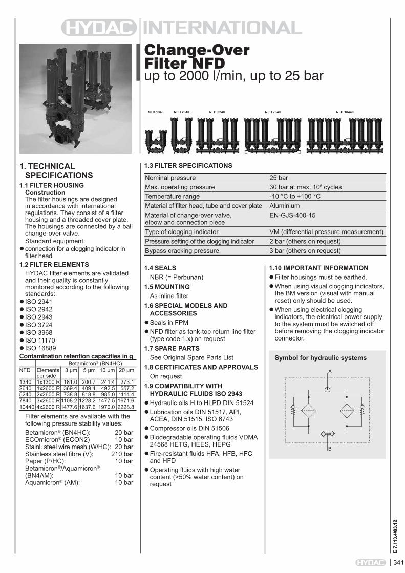
Change-Over Filter NFDup to 2000 l/min, up to 25 bar
1. TECHNiCAL SPECiFiCATiONS
1.1 FiLTER HOUSiNGConstruction The filter housings are designed in accordance with international regulations. They consist of a filter housing and a threaded cover plate. The housings are connected by a ball change-over valve.Standard equipment:
connection for a clogging indicator in filter head
1.2 FiLTER ELEMENTSHYDAC filter elements are validated and their quality is constantly monitored according to the following standards:
ISO 2941ISO 2942 ISO 2943 ISO 3724ISO 3968 ISO 11170ISO 16889Contamination retention capacities in g Betamicron® (BN4HC)NFD Elements 3 µm 5 µm 10 µm 20 µm per side1340 1x1300 R 181.0 200.7 241.4 273.12640 1x2600 R 369.4 409.4 492.5 557.25240 2x2600 R 738.8 818.8 985.0 1114.47840 3x2600 R 1108.2 1228.2 1477.5 1671.610440 4x2600 R 1477.6 1637.6 1970.0 2228.8
Filter elements are available with the following pressure stability values:Betamicron® (BN4HC): 20 bar ECOmicron® (ECON2) 10 bar Stainl. steel wire mesh (W/HC): 20 bar Stainless steel fibre (V): 210 bar Paper (P/HC): 10 bar Betamicron®/Aquamicron® (BN4AM): 10 bar Aquamicron® (AM): 10 bar
1.4 SEALSNBR (= Perbunan)
1.5 MOUNTiNGAs inline filter
1.6 SPECiAL MODELS AND ACCESSORiES
Seals in FPMNFD filter as tank-top return line filter
(type code 1.x) on request1.7 SPARE PARTS
See Original Spare Parts List1.8 CERTiFiCATES AND APPROVALS
On request1.9 COMPATiBiLiTY WiTH
HYDRAULiC FLUiDS iSO 2943Hydraulic oils H to HLPD DIN 51524Lubrication oils DIN 51517, API,
ACEA, DIN 51515, ISO 6743Compressor oils DIN 51506Biodegradable operating fluids VDMA
24568 HETG, HEES, HEPGFire-resistant fluids HFA, HFB, HFC
and HFDOperating fluids with high water
content (>50% water content) on request
1.10 iMPORTANT iNFORMATiONFilter housings must be earthed.When using visual clogging indicators,
the BM version (visual with manual reset) only should be used.
When using electrical clogging indicators, the electrical power supply to the system must be switched off before removing the clogging indicatorconnector.
1.3 FiLTER SPECiFiCATiONS
Nominal pressure 25 bar Max. operating pressure 30 bar at max. 106 cycles Temperature range -10 °C to +100 °C Material of filter head, tube and cover plate Aluminium Material of change-over valve, EN-GJS-400-15 elbow and connection piece Type of clogging indicator VM (differential pressure measurement) Pressure setting of the clogging indicator 2 bar (others on request) Bypass cracking pressure 3 bar (others on request)
Symbol for hydraulic systems
A
B
E 7.
113.
4/03
.12
NFD 1340 NFD 2640 NFD 5240 NFD 7840 NFD 10440

342
E 7.
113.
4/03
.12
2600 R 010 BN4HC /-VSize 1300, 2600
TypeFiltration rating in µm BN4HC, ECON2, V: 003, 005, 010, 020 P/HC: 010, 020 AM: 040 W/HC: 025, 050, 100, 200 BN4AM: 003, 010
Filter material BN4HC, ECON2, V, W/HC, P/HC, BN4AM, AM
Supplementary details V (for descriptions, see point 2.1)
2.2 REPLACEMENT ELEMENT
2.3 REPLACEMENT CLOGGiNG iNDiCATOR VM 2 D . X /-L24Type VM differential pressure measurement up to 210 bar operating pressure
Pressure setting 2 standard 2 bar, others on request
Type of clogging indicator (see point 2.1)
Modification number X the latest version is always supplied
Supplementary details L..., LED, V (for descriptions, see point 2.1)
2. MODEL CODE (also order example)2.1. COMPLETE FiLTERFilter type NFD
Filter material BN/HC Betamicron® (BN4HC) P/HC Paper ECO/N ECOmicron® (ECON2) BN/AM Betamicron®/Aquamicron® W/HC Stainless steel wire mesh AM Aquamicron® V Stainless steel fibre
Size of filter or element NFD: 1340, 2640, 5240, 7840, 10440
Operating pressure D = 25 bar
Type of change-over A = Ball
Type and size of port
NFD BN/HC 2640 D A P 10 D 2 . X /-L24
Filtration rating in µm BN/HC, ECO/N, V: 3, 5, 10, 20 P/HC: 10, 20 AM: 40 W/HC: 25, 50, 100, 200 BN/AM: 3, 10
Type of clogging indicator Y plastic blanking plug in indicator port A steel blanking plug in indicator port BM visual C electrical D visual and electrical
Type code (TKZ) 2
Modification number X the latest version is always supplied
Supplementary details B. special cracking pressure of bypass (e. g.: B6 = 6 bar) EM manual vent with shut-off valve EP permanent vent via Minimess hose KB without bypass valve L... light with appropriate voltage (24, 48, 110, 220 Volt) LED 2 light emitting diodes up to 24 Volt SB4 filling line with Ø4 mm orifice V FPM seals VKD drain fitted with ball shut-off valve 39 connection alternative (see point 2.4)
for other clogging indicators see brochure no. 7.050../..
only for clogging indicators type "D"
Further types and sizes of port on request! For examples, see point 3.3
Type Port Filter size1340 2640 5240 7840 10440
P SAE DN 100
343
E 7.
113.
4/03
.12
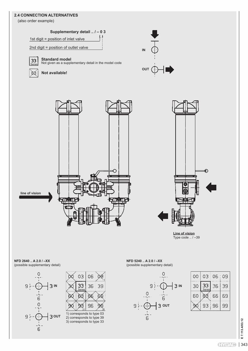
2.4 CONNECTiON ALTERNATiVES(also order example)
Supplementary detail .. / – 0 3
1st digit = position of inlet valve
2nd digit = position of outlet valve
Standard modelNot given as a supplementary detail in the model code
Not available!
Series
line of vision
Line of vision Type code .. / –39
NFD 2640 .. A 2.0 / –XX (possible supplementary detail)
NFD 5240 .. A 2.0 / –XX (possible supplementary detail)
Series Series
iN
OUT
1) corresponds to type 03 2) corresponds to type 39 3) corresponds to type 33
iN
OUT
iN
OUT

344
E 7.
113.
4/03
.12
3. FiLTER CALCULATiON / SiZiNGThe total pressure drop of a filter at a certain flow rate Q is the sum of the housing ∆p and the element ∆p and is calculated as follows:∆ptotal =∆phousing+∆pelement
∆phousing = given in diagrams (see point 3.1)∆pelement = Q • SK*/1000 • viscosity/30 (*see point 3.2) For ease of calculation, our Filter Sizing Program is available on request free of charge.NEW: Sizing online at www.hydac.com
3.1 ∆p-Q HOUSiNG CURVES BASED ON iSO 3968The housing curves apply to mineral oil with a density of 0.86 kg/dm³ and a kinematic viscosity of 30mm²/s. In this case, the differential pressure changes proportionally to the density.
3.2 GRADiENT COEFFiCiENTS (SK) FOR FiLTER ELEMENTSThe gradient coefficients in mbar/(l/min) apply to mineral oils with a kinematic viscosity of 30 mm²/s. The pressure drop changes proportionally to the change in viscosity.
∆p [b
ar]
Q [l/min]
BN4HC: 1300 R...
∆p [b
ar]
Q [l/min]
BN4HC: 2600 R...
NFD V W/HC ECON2 3 µm 5 µm 10 µm 20 µm – 3 µm 5 µm 10 µm 20 µm1300 0.5 0.4 0.3 0.2 0.045 0.8 0.6 0.4 0.32600 0.3 0.2 0.1 0.1 0.018 0.4 0.3 0.2 0.1
NFD 1340 / 2640
NFD 5240
NFD 7840
NFD 10440
∆p [b
ar]
∆p [b
ar]
∆p [b
ar]
∆p [b
ar]
Q [l/min]
Q [l/min]
Q [l/min]
Q [l/min]
3.3. OTHER CONNECTiON SiZES AND TYPES ON REQUEST!Examples:

345
E 7.
113.
4/03
.12
4. DiMENSiONS
NFD No. of Weight incl. Vol. of pressure elements element [kg] chamber [l] per side1340...2.X 1x 1300 R... 122.7 35.82640...2.X 1x 2600 R... 140.0 58.1
NFD 1340/2640
vent G1/2"
filling connection G 3/4"
port for differential pressure indicator G 1/2"
Siz
e
Siz
e
drain on contaminated side G 1/2"
INLET
OUTLET

346
E 7.
113.
4/03
.12
NFD 5240...2.X /-1+2
NFD No. of Weight incl. Vol. of pressure elements element [kg] chamber [l] per side5240...2.X 2x 2600 R... 276.8 126.45240../-1+2...2.X 1x 2600 R... and 217.4 94.3 2x 2600 R...
NFD 5240 vent G1/2"
filling connection G 3/4"
port for differential pressure indicator G 1/2"
drain on contaminated side G 1/2"
INLET
OUTLET
vent G1/2"
filling connection G 3/4"
port for differential pressure indicator G 1/2"
drain on contaminated side G 1/2"
INLET
OUTLET
347
E 7.
113.
4/03
.12
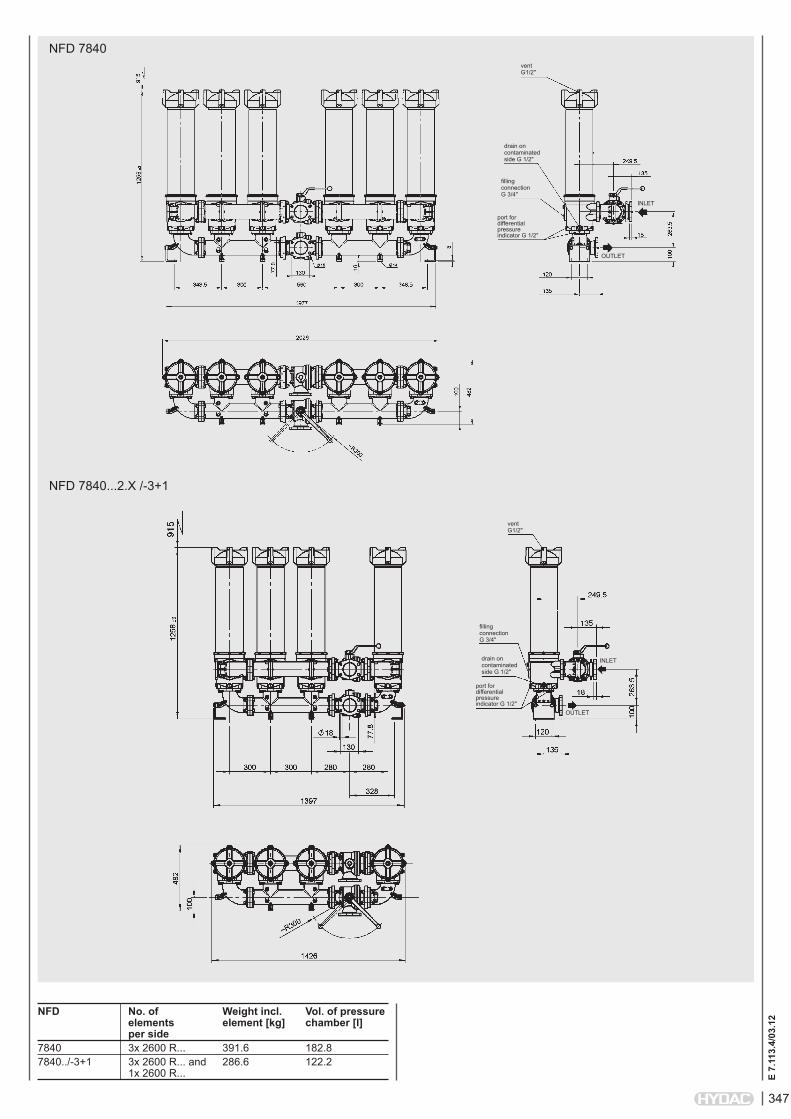
NFD 7840...2.X /-3+1
NFD No. of Weight incl. Vol. of pressure elements element [kg] chamber [l] per side7840 3x 2600 R... 391.6 182.87840../-3+1 3x 2600 R... and 286.6 122.2 1x 2600 R...
NFD 7840vent G1/2"
filling connection G 3/4"
port for differential pressure indicator G 1/2"
drain on contaminated side G 1/2"
INLET
OUTLET
vent G1/2"
filling connection G 3/4"
port for differential pressure indicator G 1/2"
drain on contaminated side G 1/2"
INLET
OUTLET
348
E 7.
113.
4/03
.12
NOTEThe information in this brochure relates to the operating conditions and applications described. For applications or operating conditions not described, please contact the relevant technical department. Subject to technical modifications.
HYDAC FiLTERTECHNiK GMBH Industriegebiet D-66280 Sulzbach/Saar, Germany Tel.: 0 68 97 / 509-01 Fax: 0 68 97 / 509-300 Internet: www.hydac.com E-mail: [email protected]
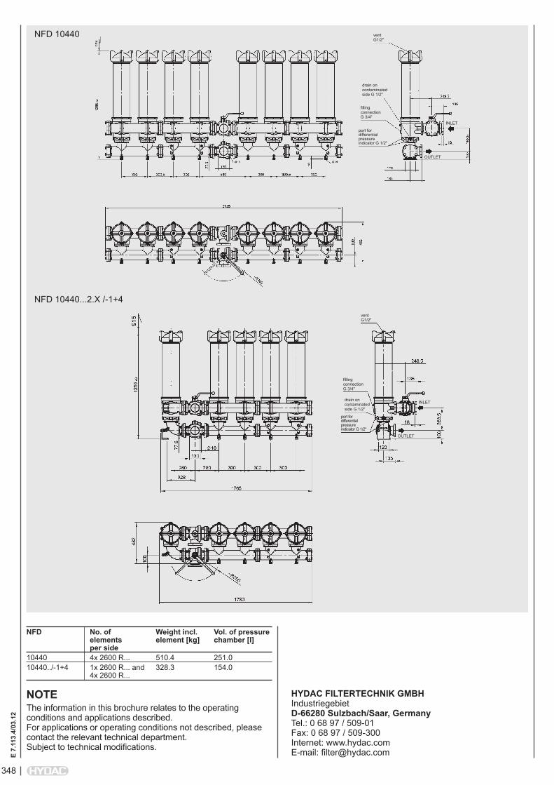
NFD 10440...2.X /-1+4
NFD No. of Weight incl. Vol. of pressure elements element [kg] chamber [l] per side10440 4x 2600 R... 510.4 251.010440../-1+4 1x 2600 R... and 328.3 154.0 4x 2600 R...
NFD 10440 vent G1/2"
filling connection G 3/4"
port for differential pressure indicator G 1/2"
drain on contaminated side G 1/2"
INLET
OUTLET
vent G1/2"
filling connection G 3/4"
port for differential pressure indicator G 1/2"
drain on contaminated side G 1/2"
INLET
OUTLET

349
E 7.
561.
5/03
.12
Change-Over Inline Filter FLNDto DIN 24550*, up to 400 l/min, up to 63 bar*Filters and filter elements also available in HYDAC dimensions
1. TECHNiCAL SPECiFiCATiONS
1.1 FiLTER HOUSiNGConstruction The filter housings are designed in accordance with international regulations. They consist of a filter head with built-in change-over valve and screw-in filter bowls.Standard equipment:
without bypass valveconnection for a clogging indicatoroil drain plug (FLND 160 to 400)1.2 FiLTER ELEMENTS
HYDAC filter elements are validated and their quality is constantly monitored according to the following standards:
ISO 2941, ISO 2942, ISO 2943, ISO 3724, ISO 3968, ISO 11170,ISO 16889
Contamination retention capacities in g Betamicron® (BN4HC)FLND 3 µm 5 µm 10 µm 20 µm60 6.5 7.3 7.8 8.0110 13.8 15.5 16.4 16.9140 18.1 20.3 21.5 22.2 Betamicron® (BN4HC)FLND 3 µm 6 µm 10 µm 25 µm40 5.2 5.6 6.3 7.063 9.2 9.9 11.1 12.8100 15.4 16.5 18.6 20.6160 27.5 29.3 33.1 36.7250 46.0 49.0 55.2 61.3400 76.2 81.3 91.4 101.5 Betamicron® (BH4HC)FLND 3 µm 5 µm 10 µm 20 µm60 4.6 4.5 5.0 5.7110 10.1 9.9 10.9 12.4140 13.3 13.0 14.3 16.3 Betamicron® (BH4HC)FLND 3 µm 6 µm 10 µm 25 µm40 4.1 4.4 5.2 6.263 7.3 7.9 9.2 11.2100 12.2 13.2 15.5 18.9160 21.8 23.9 27.8 33.8250 38.1 41.7 48.6 59.0400 63.6 69.5 81.0 98.3
Filter elements are available with the following pressure stability values:Betamicron® (BN4HC): 20 bar Betamicron® (BH4HC): 210 bar Wire mesh (W/HC, W*): 20 bar * only for FLND 40 - 140
1.4 SEALSNBR (= Perbunan)
1.5 iNSTALLATiONAs inline filter
1.6 SPECiAL MODELS AND ACCESSORiES
With bypass valveWith oil drain plug
for FLND 40 to 140 (SO184)Seals in FPM, EPDMReverse flow (RL)1.7 SPARE PARTS
See Original Spare Parts List1.8 CERTiFiCATES AND APPROVALS
On request1.9 COMPATiBiLiTY WiTH
HYDRAULiC FLUiDS iSO 2943Hydraulic oils H to HLPD DIN 51524Lubrication oils DIN 51517, API,
ACEA, DIN 51515, ISO 6743Compressor oils DIN 51506Biodegradable operating fluids VDMA
24568 HETG, HEES, HEPGFire-resistant fluids HFA, HFB, HFC
and HFDOperating fluids with high water
content (>50% water content) on request
1.10 iMPORTANT iNFORMATiON Filter housings must be earthed.When using electrical clogging
indicators, the electrical power supply to the system must be switched off before removing the clogging indicatorconnector.
1.3 FiLTER SPECiFiCATiONS
Nominal pressure 25 bar (FLND 160 to 400) 63 bar (FLND 40 to 140) Fatigue strength At nominal pressure 106 cycles from 0 to nominal pressure Temperature range -10 °C to +100 °C Material of filter head Aluminium Material of filter bowl Aluminium (FLND 100 and 140: Steel) Type of clogging indicator VM (differential pressure measurement up to 210 bar operating pressure) Pressure setting of the clogging indicator 2.5 bar or 5 bar (others on request) Bypass cracking pressure (optional) 3.5 bar or 7 bar (others on request)
Symbol for hydraulic systems
FLND 60
FLND 140
FLND 40
FLND 63
FLND 100
FLND 160
FLND 250
FLND 400
FLND 110
E 7.
561.
5/03
.12
outlet
inlet
VA = clogging indicator

350
E 7.
561.
5/03
.12
FLND BN/HC 250 D D F 10 D 1 . X /-L24
Filter type FLNDFilter material of element BN/HC Betamicron® (BN4HC) BH/HC Betamicron® (BH4HC) W/HC, W* Wire mesh Size of filter or element FLND: 40, 60, 63, 100, 110, 140, 160, 250, 400Operating pressure D = 25 bar (FLND 160 to 400) F = 63 bar (FLND 40 to 140)Type of change-over D single switching valve and check valveType and size of port to DIN 24550 ( ), possible ports ( X )Type Port Filter size ... not to ... to DIN 24550 DIN 24550 60 110 140 40 63 100 160 250 400B G ½ X X X X X C G ¾ X X X X X D G 1 X X X X X E G 1¼ X XF G 1½ X XI DN 25** X X X X X X K DN 38** X X ** Flange SAE, 3000 PSIFiltration rating in µm BN/HC, BH/HC: 3, 5, 10, 20 BN/HC, BH/HC to DIN 24550: 3, 6, 10, 25 W/HC, W*: 25, 50, 100, 200Type of clogging indicator Y plastic blanking plug in indicator port A steel blanking plug in indicator port B visual C electrical for other clogging indicators, D visual and electrical see brochure no. 7.050../.. LZ visual-mechanical / electricalType code 1 Modification number X the latest version is always suppliedSupplementary details B. bypass cracking pressure (e.g. B3.5 = 3.5 bar; B7 = 7 bar); without details = without bypass valve L... light with appropriate voltage (24V, 48V, 110V, 220V) only for clogging LED 2 light emitting diodes up to 24 Volt indicators type D AV LZ indicator with plug to AUDI and VW specification BO LZ indicator with plug and pin connection to BMW and Opel specification (M12x1) CN LZ indicator with plug to DIN 43651 with 3 LEDs (CNOMO specification) DB LZ indicator with plug to DIN 43651 with 3 LEDs (Daimler-Benz specification) D4C LZ with plug and connector to Daimler-Chrysler specification and cold start suppression 30°C BO-LED as for BO, but with progressive diode strip RL reverse flow direction SO184 oil drain plug (FLND 40 to 140) V FPM seals W suitable for HFA and HFC emulsions
2. MODEL CODE (also order example)2.1 COMPLETE FiLTER
0250 DN 010 BN4HC /-VSize 0040, 0060, 0063, 0100, 0110, 0140, 0160, 0250, 0400Type D 0060, 0110, 0140 DN to DIN 24550: 0040, 0063, 0100, 0160, 0250, 0400Filtration rating in µm BN4HC, BH4HC: 003, 005, 010, 020 BN4HC, BH4HC to DIN 24550: 003, 006, 010, 025 W/HC, W*: 025, 050, 100, 200Filter material BN4HC, BH4HC, W/HC, W*Supplementary details V, W (for descriptions, see point 2.1)
2.2 REPLACEMENT ELEMENT
2.3 REPLACEMENT CLOGGiNG iNDiCATOR VM 5 D . X /-L24Type VM differential pressure measurement up to 210 bar operating pressurePressure setting 5 standard 5 bar, others on requestType of clogging indicator (see point 2.1)Modification number X the latest version is always suppliedSupplementary details L..., LED, V, W, AV, BO, CN, DB, D4C, BO-LED (for descriptions see Point 2.1) * only for FLND 40 - 140

351
E 7.
561.
5/03
.12
3. FiLTER CALCULATiON / SiZiNGThe total pressure drop of a filter at a certain flow rate Q is the sum of the housing ∆p and the element ∆p and is calculated as follows:∆ptotal =∆phousing+∆pelement
∆phousing = (see Point 3.1)
∆pelement = Q • SK* • viscosity 1000 30 (*see Point 3.2)For ease of calculation, our Filter Sizing Program is available on request free of charge.NEW: Sizing online at www.hydac.com
3.1 ∆p-Q HOUSiNG CURVES BASED ON iSO 3968The housing curves apply to mineral oil with a density of 0.86 kg/dm³ and a kinematic viscosity of 30 mm²/s. In this case, the differential pressure changes proportionally to the density.
3.2 GRADiENT COEFFiCiENTS (SK) FOR FiLTER ELEMENTSThe gradient coefficients in mbar/(l/min) apply to mineral oils with a kinematic viscosity of 30 mm²/s. The pressure drop changes proportionally to the change in viscosity.
FLND 40, 60, 63, 100, 110, 140
∆p [b
ar]
Q [l/min]FLND 160, 250, 400
∆p [b
ar]
Q [l/min]
∆p [b
ar]
Q [l/min]
BN4HC: FLND 60
∆p [b
ar]
Q [l/min]
BN4HC: FLND 110
∆p [b
ar]
Q [l/min]
BN4HC: FLND 63
∆p [b
ar]
Q [l/min]
BN4HC: FLND 100
∆p [b
ar]
Q [l/min]
BN4HC: FLND 140
FLND ... D ... BH4HC W/HC - W ... DN ... BH4HC 3 µm 5 µm 10 µm 20 µm – 3 µm 6 µm 10 µm 25 µm60 58.6 32.6 18.1 12.2 0.757 - - - -110 25.4 14.9 8.9 5.6 0.413 - - - -140 19.9 11.3 8.1 4.3 0.324 - - - -40 - - - - 0.966 40.4 24.8 16.4 10.963 - - - - 0.54 29.0 18.2 11.7 7.6100 - - - - 0.325 19.0 11.7 7.7 5.3160 - - - - 0.168 8.0 5.1 3.8 2.5250 - - - - 0.101 5.4 3.4 2.8 1.9400 - - - - 0.068 3.4 2.1 1.7 1.1
0
0.5
1
1.5
2
2.5
0 50 100 150 200 250 300 350
∆p [b
ar]
Q [l/min]
BN4HC: FLND 160
∆p [b
ar]
Q [l/min]
BN4HC: FLND 250
∆p [b
ar]
Q [l/min]
BN4HC: FLND 40
∆p [b
ar]
Q [l/min]
BN4HC: FLND 400

352
E 7.
561.
5/03
.12
4. DiMENSiONS
NOTEThe information in this brochure relates to the operating conditions and applications described. For applications or operating conditions not described, please contact the relevant technical department. Subject to technical modifications.
HYDAC FiLTERTECHNiK GMBH Industriegebiet D-66280 Sulzbach/Saar, Germany Tel.: 0 68 97 / 509-01 Fax: 0 68 97 / 509-300 Internet: www.hydac.com E-mail: [email protected]
FLND 160 - 400
FLND 40 - 140
FLND Weight incl. Vol. of pressure element [kg] chamber [l]40 6.73 2x 0.2660 6.83 2x 0.2563 7.10 2x 0.40100 11.33 2x 0.50110 7.32 2x 0.40140 11.78 2x 0.40160 9.1 2x 1.40250 9.6 2x 2.00400 12.0 2x 3.10
inlet
vent, SW5
outlet
change-over with built-in pressure equalization
drain screw, SW 10, optional
SW 27
port for differential clogging indicator
mounting bore M8, 16 deep
connection dimension 180
optional G 1/2, G 3/4, G 1, flange DN 25
FLN
D 1
00:
354.
5 FL
ND
140
: 30
2.5 FL
ND
63:
25
9 FL
ND
110
: 25
9
FLN
D 4
0:
199
FLN
D 6
0:
189.
5inlet
outlet
connection dimension 280
change-over with built-in pressure equalization
drain G3/8SW 32
size
400
: 53
4 size
250
: 38
4
size
160
:294
ØD mounting bore
port for differential clogging indicator
vent on right G 1/8, SW 5vent on left
G 1/8, SW 5
A B C DG 1 1/4 95 43 M10 x 19/22 deepG 1 1/2 98 40 M10 x 19/22 deepDN 38 95 43 M10 x 19/22 deep
353
E 7.
109.
4/03
.12
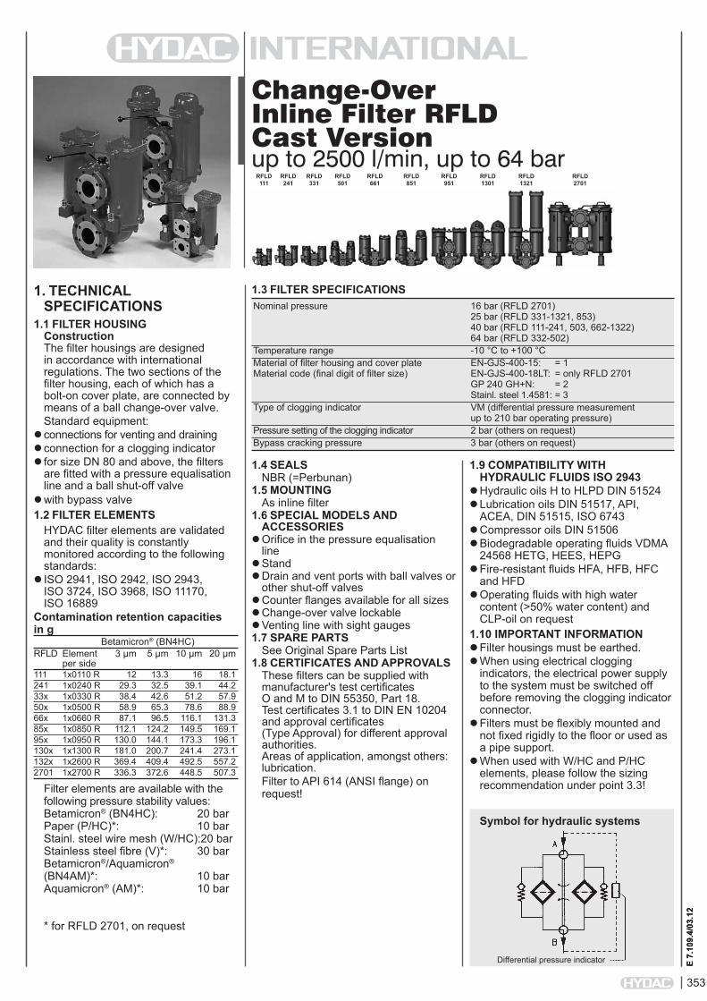
Change-Over Inline Filter RFLD Cast Versionup to 2500 l/min, up to 64 bar
1. TECHNiCAL SPECiFiCATiONS
1.1 FiLTER HOUSiNGConstruction The filter housings are designed in accordance with international regulations. The two sections of the filter housing, each of which has a bolt-on cover plate, are connected by means of a ball change-over valve.Standard equipment:
connections for venting and drainingconnection for a clogging indicatorfor size DN 80 and above, the filters
are fitted with a pressure equalisation line and a ball shut-off valve
with bypass valve1.2 FiLTER ELEMENTS
HYDAC filter elements are validated and their quality is constantly monitored according to the following standards:
ISO 2941, ISO 2942, ISO 2943, ISO 3724, ISO 3968, ISO 11170, ISO 16889
Contamination retention capacities in g Betamicron® (BN4HC)RFLD Element 3 µm 5 µm 10 µm 20 µm per side111 1x0110 R 12 13.3 16 18.1241 1x0240 R 29.3 32.5 39.1 44.233x 1x0330 R 38.4 42.6 51.2 57.950x 1x0500 R 58.9 65.3 78.6 88.966x 1x0660 R 87.1 96.5 116.1 131.385x 1x0850 R 112.1 124.2 149.5 169.195x 1x0950 R 130.0 144.1 173.3 196.1130x 1x1300 R 181.0 200.7 241.4 273.1132x 1x2600 R 369.4 409.4 492.5 557.22701 1x2700 R 336.3 372.6 448.5 507.3
Filter elements are available with the following pressure stability values: Betamicron® (BN4HC): 20 bar Paper (P/HC)*: 10 bar Stainl. steel wire mesh (W/HC): 20 bar Stainless steel fibre (V)*: 30 bar Betamicron®/Aquamicron® (BN4AM)*: 10 bar Aquamicron® (AM)*: 10 bar * for RFLD 2701, on request
1.4 SEALSNBR (=Perbunan)
1.5 MOUNTiNGAs inline filter
1.6 SPECiAL MODELS AND ACCESSORiES
Orifice in the pressure equalisation line
StandDrain and vent ports with ball valves or
other shut-off valvesCounter flanges available for all sizesChange-over valve lockableVenting line with sight gauges1.7 SPARE PARTS
See Original Spare Parts List1.8 CERTiFiCATES AND APPROVALS
These filters can be supplied with manufacturer's test certificates O and M to DIN 55350, Part 18. Test certificates 3.1 to DIN EN 10204 and approval certificates (Type Approval) for different approval authorities. Areas of application, amongst others: lubrication.Filter to API 614 (ANSI flange) on request!
1.9 COMPATiBiLiTY WiTH HYDRAULiC FLUiDS iSO 2943
Hydraulic oils H to HLPD DIN 51524Lubrication oils DIN 51517, API,
ACEA, DIN 51515, ISO 6743Compressor oils DIN 51506Biodegradable operating fluids VDMA
24568 HETG, HEES, HEPGFire-resistant fluids HFA, HFB, HFC
and HFDOperating fluids with high water
content (>50% water content) and CLP-oil on request
1.10 iMPORTANT iNFORMATiONFilter housings must be earthed.When using electrical clogging
indicators, the electrical power supply to the system must be switched off before removing the clogging indicatorconnector.
Filters must be flexibly mounted and not fixed rigidly to the floor or used as a pipe support.
When used with W/HC and P/HC elements, please follow the sizing recommendation under point 3.3!
1.3 FiLTER SPECiFiCATiONS Nominal pressure 16 bar (RFLD 2701) 25 bar (RFLD 331-1321, 853) 40 bar (RFLD 111-241, 503, 662-1322) 64 bar (RFLD 332-502) Temperature range -10 °C to +100 °C Material of filter housing and cover plate EN-GJS-400-15: = 1 Material code (final digit of filter size) EN-GJS-400-18LT: = only RFLD 2701 GP 240 GH+N: = 2 Stainl. steel 1.4581: = 3 Type of clogging indicator VM (differential pressure measurement up to 210 bar operating pressure) Pressure setting of the clogging indicator 2 bar (others on request) Bypass cracking pressure 3 bar (others on request)
Symbol for hydraulic systems
E 7.
109.
4/03
.12
RFLD 111
Differential pressure indicator
RFLD 241
RFLD 331
RFLD 501
RFLD 661
RFLD 851
RFLD 951
RFLD 1301
RFLD 1321
RFLD 2701

354
E 7.
109.
4/03
.12
RFLD BN/HC 851 D A L 10 D 1 . X /-L24
Filter type RFLDFilter material of element BN/HC Betamicron® (BN4HC) P/HC Paper* AM Aquamicron®* V Stainless steel fibre* W/HC Wire mesh BN/AM Betamicron®/Aquamicron®*Size of filter or element EN-GJS-400-15: 111, 241, 331, 501, 661, 851, 951, 1301, 1321 EN-GJS-400-18LT: 2701 GP 240 GH+N: 332, 502, 662, 852, 952, 1302, 1322 Stainl. steel 1.4581: 503, 853Operating pressure C = 16 bar RFLD 2701 D = 25 bar RFLD 331-1321, 853 E = 40 bar RFLD 111-241, 503, 662-1322 F = 64 bar RFLD 332-502Type of change-over A BallType and size of port EN-GJS-400-15 + EN-GJS-400-LT18 () GP 240 GH+N (X); 1.4581 ()Type Port Filter sizes
111 241 331332
501502503
661662
851852853
951952
13011302
13211322
2701
D G 1 F G 1½ I SAE DN 25 J DIN DN 50 x XK SAE DN 40 L SAE DN 50 X X M SAE DN 65 Q DIN DN 80 x XR DIN DN 100 x x xS SAE/DIN DN 80 T SAE/DIN DN 100 V DIN DN 150 Other nominal bores, and ANSI flange version on requestFiltration rating in µm BN/HC, V*: 3, 5, 10, 20 P/HC*: 10, 20 AM*: 40 W/HC: 25, 50, 100, 200 BN/AM*: 3, 10Type of clogging indicator Y plastic blanking plug in indicator port A stainless steel blanking plug in indicator port B visual for other clogging indicators, C electrical see brochure no. 7.050../.. D visual and electricalType code 1 Modification number X the latest version is always suppliedSupplementary details B. special cracking pressure of bypass (e.g. B1 = 1 bar)DE differential pressure measurement across elementKB without bypass valve L... light with appropriate voltage (24V, 48V, 110V, 220V) only for clogging indicators LED 2 light emitting diodes up to 24 Volt type "D" SAK contamination retainerSB pressure equalisation line (SB2 = with 2mm orifice)STV stand V FPM seals
2. MODEL CODE (also order example)2.1 COMPLETE FiLTER
0850 R 010 BN4HC /-VSize 0110, 0240, 0330, 0500, 0660, 0850, 0950, 1300, 2600, 2700Type RFiltration rating in µm BN4HC, V*: 003, 005, 010, 020 P/HC*: 010, 020 AM*: 040 W/HC: 025, 050, 100, 200 BN4AM*: 003, 010Filter material BN4HC, V*, W/HC, P/HC*, BN4AM*, AM*Supplementary details V (for descriptions, see point 2.1.)
2.2 REPLACEMENT ELEMENT
2.3 REPLACEMENT CLOGGiNG iNDiCATOR VM 2 D . X /-L24Type VM differential pressure measurement up to 210 bar operating pressurePressure setting 2 standard 2 bar, others on requestType of clogging indicator (see Point 2.1.)Modification number X the latest version is always suppliedSupplementary details L..., LED, V (for descriptions, see point 2.1.)
* for RFLD 2701 on request!

355
E 7.
109.
4/03
.12
0.00
0.05
0.10
0.15
0.20
0.25
0.30
0 500 1000 1500 2000 2500
3. FiLTER CALCULATiON / SiZiNGThe total pressure drop of a filter at a certain flow rate Q is the sum of the housing ∆p and the element ∆p and is calculated as follows:∆ptotal = ∆phousing + ∆pelement
∆phousing = (see Point 3.1)
∆pelement = Q • SK* • viscosity 1000 30 (*see point 3.2) For ease of calculation, our Filter Sizing Program is available on request free of charge.NEW: Sizing online at www.hydac.com
3.1 ∆p-Q HOUSiNG CURVES BASED ON iSO 3968The housing curves apply to mineral oil with a density of 0.86 kg/dm³ and a kinematic viscosity of 30mm²/s. In this case, the differential pressure changes proportionally to the density.
RFLD 111
∆p [b
ar]
Q [l/min]RFLD 241
∆p [b
ar]
Q [l/min]
RFLD 331, 332, 501, 502, 503
∆p [b
ar]
Q [l/min]
RFLD 661, 662, 851, 852, 853
∆p [b
ar]
Q [l/min]
RFLD 951, 952, 1301, 1302, 1321, 1322
∆p [b
ar]
Q [l/min]
3.2 GRADiENT COEFFiCiENTS (SK) FOR FiLTER ELEMENTSThe gradient coefficients in mbar/(l/min) apply to mineral oils with a kinematic viscosity of 30 mm²/s. The pressure drop changes proportionally to the change in viscosity.
RFLD V W/HC 3 µm 5 µm 10 µm 20 µm –110 7.6 5.1 3.0 2.0 0.502240 3.2 2.6 1.7 1.2 0.228330 2.1 1.7 1.1 0.8 0.164500 1.5 1.2 0.8 0.5 0.109660 1.0 0.8 0.6 0.4 0.081850 0.8 0.6 0.4 0.3 0.063950 0.7 0.6 0.4 0.2 0.0541300 0.5 0.4 0.3 0.2 0.0452600 0.3 0.2 0.1 0.1 0.0222700 – – – – 0.038
∆p [b
ar]
Q [l/min]
BN4HC: RFLD 660
∆p [b
ar]
Q [l/min]
BN4HC: RFLD 850
∆p [b
ar]
Q [l/min]
BN4HC: RFLD 110
∆p [b
ar]
Q [l/min]
BN4HC: RFLD 500
∆p [b
ar]
Q [l/min]
BN4HC: RFLD 240
∆p [b
ar]
Q [l/min]
BN4HC: RFLD 330
RFLD 2701
∆p [b
ar]
Q [l/min]

356
E 7.
109.
4/03
.12
∆p [b
ar]
Q [l/min]
BN4HC: RFLD 950∆p
[bar
]
Q [l/min]
BN4HC: RFLD 1300
∆p [b
ar]
Q [l/min]
BN4HC: RFLD 2600
3.3 SiZiNG RECOMMENDATiONFilter type Connection Qmax when using W/HC and P/HC elementsRFLD 111 G1 70 l/min SAE DN 25 70 l/minRFLD 241 G 1½ 170 l/min SAE DN 40 170 l/minRFLD 331 SAE DN 40 170 l/min RFLD 331/332 SAE DN 50 260 l/min RFLD 332 DIN DN 50 260 l/minRFLD 501 SAE DN 40 170 l/min RFLD 501/502 SAE DN 50 260 l/min RFLD 502/503 DIN DN 50 260 l/minRFLD 661 SAE DN 50 260 l/min SAE DN 65 260 l/min SAE /DIN DN 80 480 l/min RFLD 662 DIN DN 80 480 l/minRFLD 851 SAE DN 50 260 l/min SAE DN 65 260 l/min RFLD 851/853 SAE/DIN DN 80 480 l/min RFLD 852 DIN DN 80 480 l/minRFLD 951 SAE/DIN DN 80 480 l/min SAE/DIN DN 100 900 l/min RFLD 952 DIN DN 100 900 l/minRFLD 1301/1321 SAE/DIN DN 80 480 l/min SAE/DIN DN 100 900 l/min RFLD 1302/1322 DIN DN 100 900 l/minRFLD 2701 DIN DN 150 2500 l/min
∆p [b
ar]
Q [l/min]
BN4HC: RFLD 2700
0
0.1
0.2
0.3
0.4
0.5
0.6
0.7
0.8
0.9
1
0 500 1000 1500 2000 2500 3000
3 µm 5 µm
10 µm
20 µm

357
E 7.
109.
4/03
.12
RFLD Flange Threaded b1 b2 b3 d1 d2 h1 h2 h3 h5 h7 l M1 t1 Weight Volume of connection 1) connection 2) (Nm) including pressure element chamber [kg] [l]111 DN 25 (1") G 1 233 157 63 G ¼ M12 263 80 132 80 175 173 24 25 17 2 x 0.60241 DN 40 (1½") G 1½ 302 167 75 G ¼ M12 312 95 155 140 210 216 40 18 27 2 x 1.40331 DN 40 (1½") - 396 167 75 G ½ M12 302 95 145 140 200 216 40 18 33 2 x 2.30331 DN 50 (2") - 380 187 85 G ½ M12 323 110 140 165 200 216 45 18 37 2 x 2.40501 DN 40 (1½") - 396 167 75 G ½ M12 382 95 145 140 280 216 45 18 35 2 x 3.00501 DN 50 (2") - 380 187 85 G ½ M12 400 110 140 165 280 216 45 18 39 2 x 3.101) Flange connection to SAE J 518 C (standard pressure range 3000 psi) 2) Threaded connection to ISO 228
4. DiMENSiONSRFLD 111-501
RFLD Flange b1 b2 b3 d1 h1 h2 h3 h5 h7 l M1 t1 Weight Volume of connection 1) (Nm) including pressure element chamber [kg] [l]661 DN 50 (2") 496 187 85 M12 460 110 282 165 340 216 150 18 56 2 x 6.80661 DN 65 (2½") 496 252 85 M12 472 110 282 165 340 216 150 18 74 2 x 6.80661 DN 80 (3") 490 222 102 M12 566 230 210 230 340 301 150 23 82 2 x 8.20851 DN 50 (2") 496 187 85 M12 544 110 282 165 420 216 150 18 62 2 x 8.10851 DN 65 (2½") 496 252 85 M12 556 110 282 165 420 216 150 18 80 2 x 8.10851 DN 80 (3") 490 222 102 M12 650 230 210 230 420 301 150 23 88 2 x 9.50951 DN 80 (3") 548 222 102 M12 595 230 243 230 370 301 250 23 105 2 x 10.80951 DN 100 (4") 555 248 118 M16 640 250 238 250 370 301 250 23 120 2 x 13.001301 DN 80 (3") 548 222 102 M12 701 230 243 230 490 301 250 23 110 2 x 13.801301 DN 100 (4") 555 248 118 M16 746 250 238 250 490 301 250 23 125 2 x 16.001321 DN 80 (3") 548 222 102 M12 1262 230 804 230 950 301 250 23 167 2 x 28.801321 DN 100 (4") 555 248 118 M16 1307 250 799 250 950 301 250 23 167 2 x 31.001) Flange connection to SAE J 518 C (standard pressure range 3000 psi) DIN flange connection to DIN 2501/1 for PN 25/40 (sealing strip "D" or "E")
RFLD 661-1321
port for clogging indicator
outlet
threaded/flange connectiondrain on clean side G 1/4
drain on contaminated side RFLD 111/241 d1
inlet
shape of cover plate for size 501
drain on contaminated side RFLD 331/501 d1
type code label
flow direction is cut into spindletorque value for cover plate screws M1
vent G1/2
shape of cover plate for size 851, 1301
port for clogging indicator
drain on contaminated side G 1/2
flange connection to DIN/SAEdrain on clean side G 1/2
inlet
outlet
type code label
flow direction is cut into spindle
torque value for cover plate screws M1vent
G1/2pressure equalisation line
358
E 7.
109.
4/03
.12
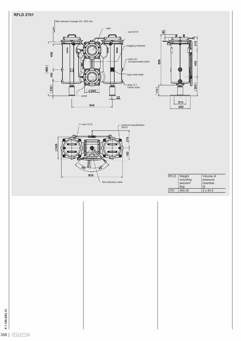
RFLD 2701filter element change min. 550 mm
clogging indicator
drain G1 (contaminated side)
drain G 1 (clean side)
type code label
vent G1/4
flow direction mark
RFLD Weight Volume of including pressure element chamber [kg] [l]2701 304.00 2 x 44.0
inlet
pressure equalisation DN15
vent G1/2
outlet

359
E 7.
109.
4/03
.12
RFLD 332, 502, 503
RFLD Flange b1 b2 b3 d1 h1 h2 h3 h4 h5 l M1 t1 Weight Volume of connection 1) (Nm) including pressure element chamber [kg] [l]662 DN 80 (3") 495 222 102 M12 574 230 210 340 230 301 150 23 82 2 x 8.20852 DN 80 (3") 495 222 102 M12 665 230 210 420 230 301 150 23 88 2 x 9.50853 DN 80 (3") 495 222 102 M12 665 230 210 420 230 301 150 23 88 2 x 9.50952 DN 100 (4") 573 248 118 M16 672 250 238 380 250 301 250 17 120 2 x 13.001302 DN 100 (4") 573 248 118 M16 745 250 238 490 250 301 250 17 125 2 x 16.001322 DN 100 (4") 573 248 118 M16 1307 250 238 950 250 301 250 17 167 2 x 31.001) Flange connection to SAE J 518 C (standard pressure range 3000 psi) DIN flange connection to DIN 2501/1 for PN 25/40 (sealing strip "D" or "E")
RFLD 662-1322, 853
shape of cover plate for RFLD 502/503
appr
ox.
clogging indicator
drain G1 drain G 3/4
M 1
6 / 2
4 de
ep
type code label
vent G3/4
flow direction is cut into spindle
flow direction is cut into spindle
type code label
torque value forcover plate screws M1
shape of cover plate for sizes 852/853/1302
pressure equalisation line vent G3/4
drai
n G
3/4
clog
ging
indi
cato
r
RFLD Weight Volume of including pressure element chamber [kg] [l]332 37 2 x 2.40502 39 2 x 3.10503 39 2 x 3.10

360
E 7.
109.
4/03
.12
NOTEThe information in this brochure relates to the operating conditions and applications described. For applications and operating conditions not described, please contact the relevant technical department. Subject to technical modifications.
HYDAC FiLTERTECHNiK GMBH Industriegebiet D-66280 Sulzbach/Saar Tel.: 0 68 97 / 509-01 Fax: 0 68 97 / 509-300 Internet: www.hydac.com E-Mail: [email protected]
NOTES

361
E 7.
564.
3/03
.12
Change-Over Inline Filter FMNDto DIN 24550*, up to 400 l/min, up to 250 bar*Filters and filter elements also available in HYDAC dimensions (FMND 40 to 140 only)
1. TECHNiCAL SPECiFiCATiONS
1.1 FiLTER HOUSiNGConstruction The filter housings are designed in accordance with international regulations. They consist of a filter head with integrated change-over valve and screw-in filter bowls.Standard equipment:
without bypass valveconnection for a clogging indicatoroil drain plug
(FMND 160 to 400)1.2 FiLTER ELEMENTS
HYDAC filter elements are validated and their quality is constantly monitored according to the following standards:
ISO 2941ISO 2942 ISO 2943 ISO 3724ISO 3968 ISO 11170ISO 16889Contamination retention capacities in g Betamicron® (BN4HC)FMND 3 µm 5 µm 10 µm 20 µm60 6.5 7.3 7.8 8.0110 13.8 15.5 16.4 16.9140 18.1 20.3 21.5 22.2 Betamicron® (BN4HC)FMND 3 µm 6 µm 10 µm 25 µm40 5.2 5.6 6.3 7.063 9.2 9.9 11.1 12.8100 15.4 16.5 18.6 20.6160 27.5 29.3 33.1 36.7250 46.0 49.0 55.2 61.3400 76.2 81.3 91.4 101.5 Betamicron® (BH4HC)FMND 3 µm 5 µm 10 µm 20 µm60 4.6 4.5 5.0 5.7110 10.1 9.9 10.9 12.4140 13.3 13.0 14.3 16.3 Betamicron® (BH4HC)FMND 3 µm 6 µm 10 µm 25 µm40 4.1 4.4 5.2 6.263 7.3 7.9 9.2 11.2100 12.2 13.2 15.5 18.9160 21.8 23.9 27.8 33.8250 38.1 41.7 48.6 59.0400 63.6 69.5 81.0 98.3
Filter elements are available with the following pressure stability values:Betamicron® (BN4HC): 20 bar Betamicron® (BH4HC): 210 bar Wire mesh (W/HC, W*): 20 bar
1.4 SEALSNBR (= Perbunan)
1.5 iNSTALLATiONAs inline filter
1.6 SPECiAL MODELS AND ACCESSORiES
With bypass valveOil drain plug
(FMND 40 to 140 = SO184)Seals in FPM, EPDMReverse flow (RL)1.7 SPARE PARTS
See Original Spare Parts List1.8 CERTiFiCATES AND APPROVALS
On request1.9 COMPATiBiLiTY WiTH
HYDRAULiC FLUiDS iSO 2943Hydraulic oils H to HLPD DIN 51524Lubrication oils DIN 51517, API,
ACEA, DIN 51515, ISO 6743Compressor oils DIN 51506Biodegradable operating fluids VDMA
24568 HETG, HEES, HEPGFire-resistant fluids HFA, HFB, HFC
and HFDOperating fluids with high water
content (>50% water content) on request* only for FMND 40 - 140
1.10 iMPORTANT iNFORMATiON Filter housings must be earthed.When using electrical clogging
indicators, the electrical power supply to the system must be switched off before removing the clogging indicatorconnector.
1.3 FiLTER SPECiFiCATiONS
Nominal pressure 210 bar (FMND 160 to 400) 250 bar (FMND 40 to 140) Fatigue strength At nominal pressure 106 cycles from 0 to nominal pressure Temperature range -10 °C to +100 °C Material of filter head EN-GJS-400-15 Material of filter bowl Steel Type of indicator VM (Diff. pressure indicator up to 210 bar operating pressure) VD (Diff. pressure indicator up to 420 bar operating pressure) Pressure setting of the clogging indicator 2.5 bar or 5 bar (others on request) Bypass cracking pressure (optional) 3.5 bar or 7 bar (others on request)
Symbol for hydraulic systems
FMND 60
FMND 140
FMND 40
FMND 63
FMND 100
FMND 160
FMND 250
FMND 400
FMND 110
E 7.
564.
3/03
.12
outlet
inlet
VA = clogging indicator

362
E 7.
564.
3/03
.12
FMND BN/HC 250 L D F 10 D 1 . X /-L24
Filter type FMNDFilter material of element BN/HC Betamicron® (BN4HC) BH/HC Betamicron® (BH4HC) W/HC, W* Stainless steel wire mesh Size of filter or element FMND: 40, 60, 63, 100, 110, 140, 160, 250, 400Operating pressure L = 210 bar (FMND 160 to 400) M = 250 bar (FMND 40 to 140)Type of change-over D single switching valve and check valveType and size of port to DIN 24550 ( ), possible ports ( X )Type Port Filter size ... not to ... to DIN 24550 DIN 24550 60 110 140 40 63 100 160 250 400B G ½ X X X X X C G ¾ X X X X X D G 1 X X X X X E G 1¼ X XF G 1½ X XI DN 25* X X X X X X K DN 38* X X *Flange SAE, 3000 PSIFiltration rating in µm BN/HC, BH/HC: 3, 5, 10, 20 BN/HC, BH/HC to DIN 24550: 3, 6, 10, 25 W/HC, W*: 25, 50, 100, 200 Type of clogging indicator Y plastic blanking plug in indicator port A steel blanking plug in indicator port B visual C electrical for other clogging indicators, D visual and electrical see brochure no. 7.050../.. LZ visual-mechanical / electricalType code 1 Modification number X the latest version is always suppliedSupplementary details B. bypass cracking pressure (e.g. B3.5 = 3.5 bar; B7 = 7 bar); without details = without bypass valve L... light with appropriate voltage (24V, 48V, 110V, 220V) only for clogging LED 2 light emitting diodes up to 24 Volt indicators type D AV LZ indicator with plug to AUDI and VW specification BO LZ indicator with plug and pin connections to BMW and Opel specification (M12x1) CN LZ indicator with plug to DIN 43651 with 3 LEDs (CNOMO specification) DB LZ indicator with plug to DIN 43651 with 3 LEDs (Daimler-Benz specification) D4C LZ with plug and connector to Daimler-Chrysler specification and cold start suppression 30 °C BO-LED as for BO, but with diode strip RL reverse flow direction SO184 oil drain plug (FMND 40 to 140) V FPM seals W suitable for HFA and HFC emulsions
2. MODEL CODE (also order example)2.1 COMPLETE FiLTER
0250 DN 010 BN4HC /-VSize 0040, 0060, 0063, 0100, 0110, 0140, 0160, 0250, 0400Type D 0060, 0110, 0140 DN to DIN 24550: 0040, 0063, 0100, 0160, 0250, 0400Filtration rating in µm BN4HC, BH4HC: 003, 005, 010, 020 BN4HC, BH4HC to DIN 24550: 003, 006, 010, 025 W/HC, W*: 025, 050, 100, 200 Filter material BN4HC, BH4HC, W/HC, W*Supplementary details V, W (for descriptions, see point 2.1)
2.2 REPLACEMENT ELEMENT
2.3 REPLACEMENT CLOGGiNG iNDiCATOR VM 5 D . X /-L24Type of indicator VM differential pressure indicator up to 210 bar operating pressure VD differential pressure indicator 420 bar operating pressurePressure setting 5 standard 5 bar, others on requestType of clogging indicator (see point 2.1)Modification number X the latest version is always suppliedSupplementary details L..., LED, V, W, AV, BO, CN, DB, D4C, BO-LED (for descriptions see Point 2.1)* only for FMND 40 - 140

363
E 7.
564.
3/03
.12
3. FiLTER CALCULATiON / SiZiNGThe total pressure drop of a filter at a certain flow rate Q is the sum of the housing ∆p and the element ∆p and is calculated as follows:∆ptotal =∆phousing+∆pelement
∆phousing = (see Point 3.1)
∆pelement = Q • SK* • viscosity 1000 30 (*see Point 3.2)For ease of calculation, our Filter Sizing Program is available on request free of charge.NEW: Sizing online at www.hydac.com
3.1 ∆p-Q HOUSiNG CURVES BASED ON iSO 3968The housing curves apply to mineral oil with a density of 0.86 kg/dm³ and a kinematic viscosity of 30 mm²/s. In this case, the differential pressure changes proportionally to the density.
FMND 40, 60, 63, 100, 110, 140
∆p [b
ar]
Q [l/min]FMND 160, 250, 400
∆p [b
ar]
Q [l/min]
0
0,5
1
1,5
2
2,5
0 50 100 150 200 250 300 350
3.2 GRADiENT COEFFiCiENTS (SK) FOR FiLTER ELEMENTSThe gradient coefficients in mbar/(l/min) apply to mineral oils with a kinematic viscosity of 30 mm²/s. The pressure drop changes proportionally to the change in viscosity.
∆p [b
ar]
Q [l/min]
BN4HC: FMND 60
∆p [b
ar]
Q [l/min]
BN4HC: FMND 110
∆p [b
ar]
Q [l/min]
BN4HC: FMND 63
∆p [b
ar]
Q [l/min]
BN4HC: FMND 100
∆p [b
ar]
Q [l/min]
BN4HC: FMND 140
FMND ... D ... BH4HC W/HC - W ... DN ... BH4HC 3 µm 5 µm 10 µm 20 µm – 3 µm 6 µm 10 µm 25 µm60 58.6 32.6 18.1 12.2 0.757 - - - -110 25.4 14.9 8.9 5.6 0.413 - - - -140 19.9 11.3 8.1 4.3 0.324 - - - -40 - - - - 0.966 40.4 24.8 16.4 10.963 - - - - 0.54 29.0 18.2 11.7 7.6100 - - - - 0.325 19.0 11.7 7.7 5.3160 - - - - 0.168 8.0 5.1 3.8 2.5250 - - - - 0.101 5.4 3.4 2.8 1.9400 - - - - 0.068 3.4 2.1 1.7 1.1
∆p [b
ar]
Q [l/min]
BN4HC: FMND 160
∆p [b
ar]
Q [l/min]
BN4HC: FMND 250
∆p [b
ar]
Q [l/min]
BN4HC: FMND 40
∆p [b
ar]
Q [l/min]
BN4HC: FMND 400
364
E 7.
564.
3/03
.12
4. DiMENSiONS
NOTEThe information in this brochure relates to the operating conditions and applications described. For applications and operating conditions not described, please contact the relevant technical department. Subject to technical modifications.
HYDAC FiLTERTECHNiK GMBH Industriegebiet D-66280 Sulzbach/Saar, Germany Tel.: 0 68 97 / 509-01 Fax: 0 68 97 / 509-300 Internet: www.hydac.com E-mail: [email protected]
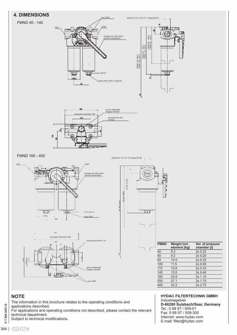
FMND 160 - 400
FMND 40 - 140
FMND Weight incl. Vol. of pressure element [kg] chamber [l]40 9.2 2x 0.2260 9.2 2x 0.20 63 10.5 2x 0.33100 11.5 2x 0.50110 10.8 2x 0.33140 12.0 2x 0.40160 23.9 2x 1.10250 27.1 2x 1.70400 32.2 2x 2.70
inlet
vent, SW5
outlet
change-over with built-in pressure equalization
drain screw, SW 10, optional
SW 27
port for differential clogging indicator
mounting bore M8, 16 deep
connection dimension 180
optional G 1/2, G 3/4, G 1, flange DN 25
FMN
D 1
00: 3
52.5
FM
ND
140
: 300
.5
FMN
D 6
3:
259.
5 FM
ND
110
: 259
.5
FMN
D 4
0:
199.
5 FM
ND
60:
19
0.0
inlet outlet
change-over with built-in pressure equalization
drain G3/8
mounting bore M12 x 19
port for differential clogging indicator
connection dimension 280
vent, SW5
optional G1 1/4, G1 1/2, flange DN 38

365
E 7.
553.
12/0
3.12
Change-Over Pressure Filter DFDKup to 2500 l/min, up to 315 bar
1. TECHNiCAL SPECiFiCATiONS
1.1 FiLTER HOUSiNGConstruction The filter housings are designed in accordance with international regulations. They consist of a filter head with screw-in filter bowls.Standard equipment:
ball change-over valvetwo-piece filter bowl for DFDK 990,
1320 (as an option for DFDK 660)connection for a clogging indicatordrain screw with pressure reliefpressure equalization line
(for size DFDK 330 and above)1.2 FiLTER ELEMENTS
HYDAC filter elements are validated and their quality is constantly monitored according to the following standards:
ISO 2941, ISO 2942, ISO 2943, ISO 3724, ISO 3968, ISO 11170 ISO 16889
Contamination retention capacities in g
Betamicron® (BN4HC)DFDK Elements
per side3 µm 5 µm 10 µm 20 µm
30 1x0030 D 4.6 5.1 5.4 5.660 1x0060 D 6.5 7.3 7.8 8.0110 1x0110 D 13.8 15.5 16.4 16.9140 1x0140 D 18.1 20.3 21.5 22.2160 1x0160 D 19.8 22.2 23.5 24.3240 1x0240 D 32.3 36.3 38.4 39.6280 1x0280 D 70.6 79.3 83.9 86.6330 1x0330 D 47.2 53.1 56.1 57.9500 1x0500 D 76.9 86.5 91.5 94.4660 1x0660 D 102.2 114.9 121.5 125.4990 1x0990 D 154.5 173.7 183.7 189.51320 1x1320 D 209.9 236.0 249.6 257.51320.3.X 1x1320 D 209.9 236.0 249.6 257.52640.3.X 2x1320 D 419.8 472.0 499.2 515.03960.3.X 3x1320 D 629.7 708.0 748.8 772.5
Betamicron® (BH4HC)DFDK Elements
per side3 µm 5 µm 10 µm 20 µm
30 1x0030 D 3.0 2.9 3.2 3.760 1x0060 D 4.6 4.5 5.0 5.7110 1x0110 D 10.1 9.9 10.9 12.4140 1x0140 D 13.3 13.0 14.3 16.3160 1x0160 D 12.9 12.6 13.9 15.9240 1x0240 D 21.6 21.1 23.2 26.5280 1x0280 D 48.1 47.1 51.8 59.1330 1x0330 D 34.6 33.9 37.2 42.5500 1x0500 D 57.5 56.3 61.8 70.5660 1x0660 D 76.8 75.2 82.6 94.3990 1x0990 D 111.8 109.4 120.2 137.21320 1x1320 D 153.8 150.7 165.5 188.81320.3.X 1x1320 D 153.8 150.7 165.5 188.82640.3.X 2x1320 D 307.6 301.4 331.0 377.63960.3.X 3x1320 D 461.4 452.1 496.5 566.4
Filter elements are available with the following pressure stability values:Betamicron® (BN4HC): 20 bar Betamicron® (BH4HC): 210 bar Wire mesh (W/HC,W): 20 bar Stainless steel fibre (V): 210 bar
1.4 SEALSNBR (= Perbunan)
1.5 iNSTALLATiONAs inline filter
1.6 SPECiAL MODELS AND ACCESSORiESPressure equalization line DFDK 160 - 280
1.7 SPARE PARTSSee Original Spare Parts List
1.8 CERTiFiCATES AND APPROVALSOn request
1.9 COMPATiBiLiTY WiTH HYDRAULiC FLUiDS iSO 2943
Hydraulic oils H to HLPD DIN 51524Lubrication oils DIN 51517, API,
ACEA, DIN 51515, ISO 6743Compressor oils DIN 51506Biodegradable operating fluids VDMA
24568 HETG, HEES, HEPGFire-resistant fluids HFA, HFB, HFC
and HFDOperating fluids with high water
content (>50% water content) and CLP-oil on request
1.10 iMPORTANT iNFORMATiON Filter housings must be earthed.When using electrical clogging
indicators, the electrical power supply to the system must be switched off before removing the clogging indicatorconnector.
1.3 FiLTER SPECiFiCATiONS
Nominal pressure 160 bar (DFDK with type code 3.X) 315 bar (DFDK with type code 1.X and 2.X) Fatigue strength At nominal pressure 106 cycles from 0 to nominal pressure Temperature range -10 °C to +100 °C (-30 °C to -10 °C: pmax= 157.5 bar) Material of filter head EN-GJS-400-15 Material of filter bowl Steel Type of clogging indicator VD (differential pressure measurement up to 420 bar operating pressure) Pressure setting of the clogging indicator 8 bar (others on request)
Symbol for hydraulic systems
DFDK 30
DFDK 110
DFDK 140
DFDK 160
DFDK 240
DFDK 280
DFDK 330
DFDK 500
DFDK 660 1.x
DFDK 660 2.x
DFDK 990 2.x
DFDK 1320 2.x
DFDK 60
E 7.
553.
12/0
3.12
DFDK 1320 3.x
DFDK 3960 3.x
DFDK 2640 3.x

366
E 7.
553.
12/0
3.12
DFDK BN/HC 160 Q A F 10 D 1 . X /-L24
Filter type DFDK
Filter material of element BN/HC Betamicron® (BN4HC) V Stainless steel fibre BH/HC Betamicron® (BH4HC) W/HC, W Wire mesh
Size of filter or element DFDK: 30, 60, 110, 140, 160, 240, 280, 330, 500, 660, 990, 1320, 2640, 3960
Operating pressure Q = 315 bar K = 160 bar (only for DFDK 1320, 2640, 3960...3.x)
Type of change-over A Ball
Type and size of connectionType Connection
typeFilter size
30 60 110 140 160 240 280 330 500 660 990 1320 1320/2640/3960...3.xB G ½ C G ¾ F G1 ½ L SAE DN 50* M SAE DN 65
*DIN ISO 228 (6000 PSI)
Filtration rating in µm BN/HC, BH/HC, V: 3, 5, 10, 20 W/HC, W: 25, 50, 100, 200
Type of clogging indicator Y plastic blanking plug in indicator port A steel blanking plug in indicator port B visual for other clogging indicators, C electrical see brochure no. 7.050../.. D visual and electrical
Type code 1 model with one-piece filter bowls 2 model with two-piece filter bowls (only for DFDK 660 to 1320) 3 top-removable model (only DFDK 1320 to 3960)
Modification number X the latest version is always supplied
Supplementary details B. light with appropriate voltage (24, 48, 110, 220 Volt) only for clogging LED 2 light-emitting diodes up to 24 Volt indicators type "D" V FPM seals W suitable for HFA and HFC emulsions
2.3 REPLACEMENT CLOGGiNG iNDiCATOR VD 8 D . X /-L24
Type VD Differential pressure indicator up to 420 bar operating pressurePressure setting 8 standard 8 bar, others on requestType of clogging indicator D (see Point 2.1)Modification number X the latest version is always suppliedSupplementary details L..., LED, V, W (for descriptions, see Point 2.1)
0160 D 010 BN4HC /-V
Size 0030, 0060, 0110, 0140, 0160, 0240, 0280, 0330, 0500, 0660, 0990, 1320
Type D
Filtration rating in µm BN4HC, BH4HC, V: 003, 005, 010, 020 W/HC, W: 025, 050, 100, 200
Filter material BN4HC, BH4HC, V, W/HC, W
Supplementary details V, W (for descriptions, see Point 2.1)
2.2 REPLACEMENT ELEMENT
2. MODEL CODE (also order example)2.1 COMPLETE FiLTER

367
E 7.
553.
12/0
3.12
3. FiLTER CALCULATiON / SiZiNGThe total pressure drop of a filter at a certain flow rate Q is the sum of the housing ∆p and the element ∆p and is calculated as follows:∆ptotal =∆phousing+∆pelement
∆phousing = (see Point 3.1)
∆pelement = Q • SK* • viscosity 1000 30 (*see point 3.2) For ease of calculation, our Filter Sizing Program is available on request free of charge.NEW: Sizing online at www.hydac.com
3.1 ∆p-Q HOUSiNG CURVES BASED ON iSO 3968The housing curves apply to mineral oil with a density of 0.86 kg/dm³ and a kinematic viscosity of 30 mm²/s. In this case, the differential pressure changes proportionally to the density.
DFDK 30 ... 1.x DFDK 1320 ... 3.x
∆p [b
ar]
∆p [b
ar]
Q [l/min] Q [l/min]
DFDK 60, 110, 140 ... 1.x DFDK 2640 ... 3.x
∆p [b
ar]
∆p [b
ar]
Q [l/min] Q [l/min]
DFDK 160, 240, 280 ... 1.x DFDK 3960 ... 3.x
∆p [b
ar]
∆p [b
ar]
Q [l/min] Q [l/min]
DFDK 330, 500, 660 ... 1.x DFDK 660, 990, 1320 ... 2.x
∆p [b
ar]
Q [l/min]
0
0.5
1
1.5
2
0 200 400 600 800 1000
0
0.5
1
1.5
2
0 200 400 600 800 1000 1200
0
0.5
1
1.5
2
2.5
0 100 200 300 400 500 600 700 800

368
E 7.
553.
12/0
3.12
3.2 GRADiENT COEFFiCiENTS (SK) FOR FiLTER ELEMENTSThe gradient coefficients in mbar/(l/min) apply to mineral oils with a kinematic viscosity of 30 mm²/s. The pressure drop changes proportionally to the change in viscosity.
∆p [b
ar]
Q [l/min]
BN4HC: DFDK... 30
∆p [b
ar]
Q [l/min]
BN4HC: DFDK... 160
∆p [b
ar]
Q [l/min]
BN4HC: DFDK... 60
∆p [b
ar]
Q [l/min]
BN4HC: DFDK... 240
∆p [b
ar]
Q [l/min]
BN4HC: DFDK... 110
∆p [b
ar]
Q [l/min]
BN4HC: DFDK... 280
∆p [b
ar]
Q [l/min]
BN4HC: DFDK... 500
∆p [b
ar]
Q [l/min]
BN4HC: DFDK... 660
∆p [b
ar]
Q [l/min]
BN4HC: DFDK... 990
∆p [b
ar]
Q [l/min]
BN4HC: DFDK... 1320
∆p [b
ar]
Q [l/min]
BN4HC: DFDK... 140
∆p [b
ar]
Q [l/min]
BN4HC: DFDK... 330
DFDK V W/HC, W BH4HC 3 µm 5 µm 10 µm 20 µm – 3 µm 5 µm 10 µm 20 µm30 18.4 13.5 7.5 3.6 3.030 91.2 50.7 36.3 19.060 16.0 9.3 5.4 3.3 0.757 58.6 32.6 18.1 12.2110 8.2 5.6 3.3 2.2 0.413 25.4 14.9 8.9 5.6140 5.8 4.8 3.1 2.3 0.324 19.9 11.3 8.1 4.3160 4.6 3.2 2.3 1.4 0.284 16.8 10.4 5.9 4.4240 3.1 2.5 1.7 1.1 0.189 10.6 6.8 3.9 2.9280 2.3 1.7 1.2 0.8 0.162 5.7 3.4 1.8 1.6330 2.2 1.8 1.2 0.8 0.138 7.7 4.5 2.8 2.0500 1.5 1.2 0.8 0.5 0.091 4.2 2.6 1.5 1.2660 1.1 0.9 0.6 0.4 0.069 3.3 1.9 1.0 0.9990 0.8 0.6 0.4 0.3 0.046 2.2 1.3 0.8 0.61320 0.6 0.5 0.3 0.2 0.035 1.6 1.0 0.6 0.4
369
E 7.
553.
12/0
3.12
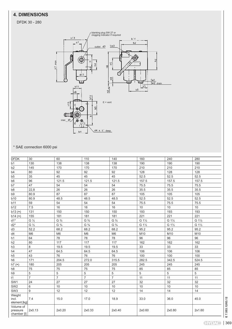
4. DiMENSiONS
blanking plug SW 27 or clogging indicator if required
deep
E = vent
inlet
outlet
DFDK 30 - 280
DFDK 30 60 110 140 160 240 280b1 130 138 138 138 190 190 190b2 145 170 170 170 210 210 210b4 80 92 92 92 128 128 128b5 35 45 45 45 52.5 52.5 52.5b6 96 121.5 121.5 121.5 157.5 157.5 157.5b7 47 54 54 54 75.5 75.5 75.5b8 22,8 26 26 26 35.5 35.5 35.5b9 80.9 87 87 87 105 105 105b10 80.9 48.5 48.5 48.5 52.5 52.5 52.5b11 59 54 54 54 75.5 75.5 75.5b12 7.5 16 16 16 10 10 10b13 (≈) 131 150 150 150 193 193 193b14 (≈) 155 181 181 181 221 221 221d1* G ½ G ¾ G ¾ G ¾ G 1½ G 1½ G 1½d2* G ½ G ¾ G ¾ G ¾ G 1½ G 1½ G 1½d3 52.2 68.2 68.2 68.2 95.2 95.2 95.2d4 M6 M6 M6 M6 M10 M10 M10h1 64 78 78 78 96 96 96h2 80 117 117 117 162 162 162h3 8 19.5 19.5 19.5 33 33 33h4 47 64.5 64.5 64.5 106 106 106h5 43 76 76 76 100 100 100h6 171 204.5 272.0 315.5 282.5 342.5 524.5h7 (≈) 180 205 205 205 245 245 245h8 75 75 75 75 85 85 85h9 5 5 5 5 5 5 5t1 7 7 7 7 11 11 11SW1 24 27 27 27 32 32 32SW2 6 10 10 10 10 10 10SW3 9 12 12 12 14 14 14Weight incl. 7.4 15.0 17.0 18.9 33.0 36.0 45.0 element [kg]Volume of pressure 2x0.13 2x0.20 2x0.33 2x0.40 2x0.60 2x0.80 2x1.60 chamber [l]
drain
* SAE connection 6000 psi

370
E 7.
553.
12/0
3.12
DFDK 330 - 660..1.x
flange connection
drain
DFDK 330 500 660 1.x 660 2.x 990 1320b1 359 359 359 359 359 359b2 385 385 385 385 385 385b3 127 127 127 127 127 127b4 265 265 265 265 265 265b5 115 115 115 115 115 115b6 309 309 309 309 309 309b7 96.8 96.8 96.8 96.8 96.8 96.8b8 60.5 60.5 60.5 60.5 60.5 60.5b9 212 212 212 212 212 212b10 44.5 44.5 44.5 44.5 44.5 44.5b11 175.5 175.5 175.5 175.5 175.5 175.5b12 13 13 13 13 13 13b13 (≈) 326 326 326 326 326 326b14 (≈) 405 405 405 405 405 405d1* DN 50 (2") DN 50 (2") DN 50 (2") DN 50 (2") DN 50 (2") DN 50 (2")d2* DN 50 (2") DN 50 (2") DN 50 (2") DN 50 (2") DN 50 (2") DN 50 (2")d3 130.2 130.2 130.2 130 130 130d4 M12 M12 M12 M12 M12 M12d5 M20 M20 M20 M20 M20 M20h1 239 239 239 239 239 239h2 190 190 190 190 190 190h3 13 13 13 13 13 13h4 98 98 98 98 98 98h5 108 108 108 108 108 108h6 357.5 450.5 527.0 521.5 677.5 843.5h7 (≈) 309 309 309 309 309 309h8 95 95 95 95 500 670t1 13 13 13 13 13 13t2 27 27 27 27 27 27Weight incl. 151.5 159.0 165.0 171.0 184.4 202.4 element [kg]Volume of pressure 2x1.50 2x2.20 2x3.00 2x3.00 2x4.50 2x6.00 chamber [l]
DFDK 660 - 1320..2.x
blanking plug SW 27 or clogging indicator as an option
outlet
drain
E = vent
pressure equalization spindle
flange connection
inlet
* SAE connection 6000 psi
371
E 7.
553.
12/0
3.12
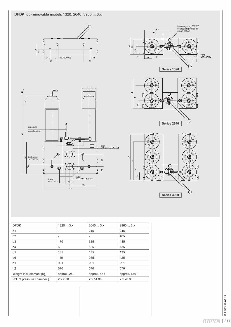
DFDK top-removable models 1320, 2640, 3960 ... 3.x
DFDK 1320 ... 3.x 2640 ... 3.x 3960 ... 3.x
b1 - 245 245
b2 - - 405
b3 170 325 485
b4 60 135 135
b5 135 135 135
b6 110 265 425
h1 991 991 991
h2 570 570 570
Weight incl. element [kg] approx. 250 approx. 445 approx. 640
Vol. of pressure chamber [l] 2 x 7.00 2 x 14.00 2 x 20.00
deep
pressure
equalization
inlet
vent
blanking plug SW 27 or clogging indicator as an option
Series 3960
Series 2640
Series 1320
outlet
test point
drain
372
E 7.
553.
12/0
3.12
NOTEThe information in this brochure relates to the operating conditions and applications described. For applications or operating conditions not described, please contact the relevant technical department. Subject to technical modifications.
HYDAC FiLTERTECHNiK GMBH Industriegebiet D-66280 Sulzbach/Saar Tel.: 0 68 97 / 509-01 Fax: 0 68 97 / 509-300 Internet: www.hydac.com E-Mail: [email protected]
NOTES