challenges in coupled thermal–hydraulics and neutronics simulations for lwr safety analysis
TRANSCRIPT
www.elsevier.com/locate/anucene
Annals of Nuclear Energy 34 (2007) 501–513
annals of
NUCLEAR ENERGY
Challenges in coupled thermal–hydraulics and neutronicssimulations for LWR safety analysis
Kostadin Ivanov *, Maria Avramova
Department of Mechanical and Nuclear Engineering, The Pennsylvania State University, 230 Reber Building, University Park,
State College, PA 16802, United States
Received 20 September 2006; received in revised form 25 February 2007; accepted 27 February 2007Available online 26 April 2007
Abstract
The simulation of nuclear power plant accident conditions requires three-dimensional (3D) modeling of the reactor core to ensure arealistic description of physical phenomena. The operational flexibility of Light Water Reactor (LWR) plants can be improved by uti-lizing accurate 3D coupled neutronics/thermal–hydraulics calculations for safety margins evaluations. There are certain requirements tothe coupling of thermal–hydraulic system codes and neutron-kinetics codes that ought to be considered. The objective of these require-ments is to provide accurate solutions in a reasonable amount of CPU time in coupled simulations of detailed operational transient andaccident scenarios. These requirements are met by the development and implementation of six basic components of the coupling meth-odologies: ways of coupling (internal or external coupling); coupling approach (integration algorithm or parallel processing); spatialmesh overlays; coupled time-step algorithms; coupling numerics (explicit, semi-implicit and implicit schemes); and coupled convergenceschemes. These principles of the coupled simulations are discussed in details along with the scientific issues associated with the develop-ment of appropriate neutron cross-section libraries for coupled code transient modeling.
The current trends in LWR nuclear power generation and regulation as well as the design of next generation LWR reactor conceptsalong with the continuing computer technology progress stimulate further development of these coupled code systems. These efforts havebeen focused towards extending the analysis capabilities as well as refining the scale and level of detail of the coupling. This article anal-yses the coupled phenomena and modeling challenges on both global (assembly-wise) and local (pin-wise) levels. The issues related to theconsistent qualification of coupled code systems as well as their application to different types of LWR transients are presented. Finally,the advances in numerical and computation techniques for coupled code simulations are summarized with outlining remainingchallenges.� 2007 Elsevier Ltd. All rights reserved.
1. Introduction
The Light Water Reactor (LWR) analysis and simula-tion in the past was characterized by efficient and accuratefuel management, based on nodal core physics methodolo-gies. These methodologies have utilized very detailed three-dimensional (3D) core neutronics models supplemented bysimplified thermal–hydraulics feedback models – usuallyone-dimensional (1D) model for Boiling Water Reactors
0306-4549/$ - see front matter � 2007 Elsevier Ltd. All rights reserved.
doi:10.1016/j.anucene.2007.02.016
* Corresponding author. Tel.: +1 814 865 0040; fax: +1 814 865 8499.E-mail addresses: [email protected] (K. Ivanov), [email protected] (M.
Avramova).
(BWRs) and a ‘‘point’’ thermal–hydraulic model for Pres-surized Water Reactors (PWRs). Limited by the availablecomputational power, earlier safety methods used a simplepoint kinetics (PK) core response in conjunction with aconservative approach for physics input in order to boundthe fuel operation. Historically, the thermal–hydraulic(T–H) system analysis codes, such as TRAC-PF1 (Schnurret al., 1992), TRAC-BF1 (Borkowski et al., 1992), andRELAP5 (Allison et al., 1990) are utilized to determinethe primary response, or in-vessel conditions, during simu-lated transients and severe accidents. As mentioned abovethe standard kinetics model built in these codes is usuallybased on PK or 1D neutron kinetics approximation.

Internal coupling
Core
Neutron Kinetics
Core
Heat Transfer Thermal-hydraulics
q
TF, TM, DM, cB
Primarycircuit
components
Exchange of parameters between all nodes
Core
Neutron Kinetics Heat Transfer
Thermal-hydraulics
p
G,H
p, H
G
Primarycircuit
components
External coupling
Fig. 1. Exchange of parameters for different ways of coupling.
502 K. Ivanov, M. Avramova / Annals of Nuclear Energy 34 (2007) 501–513
Further, the conditions, calculated utilizing these systemcodes, are used as boundary conditions for the computercodes used to determine the local (sub-channel) coreresponse. Examples of such codes are COBRA-TF (Thur-good, 1983), and CORETRAN (Dias, 1997). Unfortu-nately in such sequential calculations no consideration isgiven to the feedback effect on the local response calcula-tion. The application of the sequential methodology is lim-ited and can be used only for transient calculations whenthe feedback effects are small and can be neglected. Thedevelopment and implementation of coupling methodolo-gies, capable of incorporating full 3D models of the reactorcore into system transient codes, allows for a ‘‘best-esti-mate’’ calculation of interactions in time and space betweenboth the neutronics and thermal–hydraulics, and the corebehavior and plant dynamics.
The implementation of advanced fuel management toLWRs (higher burnup, longer cycles, utilization of burn-able absorbers, new fuel assembly and control rod designs,etc.) has prompted new safety analysis needs. To addressthese needs and to improve operational flexibility ofNuclear Power Plants (NPPs) accurate 3D coupled neu-tronics/T–H calculations have to be utilized for safety mar-gins’ evaluations. Recent progress in computer technologyhas made the development of such coupled code systemsfeasible. Considerable efforts in this direction have beenmade in many countries and organizations. Over the last15 years the Pennsylvania State University (PSU) has accu-mulated expertise and experience in developing, validatingand applying coupling methodologies for best estimatesafety analyses. The examples, utilized in this paper, arebased on the PSU coupled code systems TRAC-PF1/NEM/COBRA-TF (Ziabletsev et al., 2004), TRAC-BF1/NEM/COBRA-TF (Solis et al., 2004), and the UnitedStates (US) Nuclear Regulatory Commission (NRC) cou-pled code TRACE/PARCS (Hu et al., 2006).
2. Coupling methodologies
There are certain requirements to the coupling of T–Hsystem codes and neutron-kinetics models that ought tobe considered. The objective of these requirements is toprovide accurate solutions in a reasonable amount ofCPU time in coupled simulations of detailed operationaltransient and accident scenarios. These requirements aremet by development and implementation of six basic com-ponents of the coupling methodologies.
2.1. Ways of coupling
The core models in T–H system codes generally consistof PK models or 1D neutronics models, which are coupledto an average fluid-dynamic channel of the core region andto a corresponding average heat-structure/fuel rod model.In most codes the PK model can be related to several par-allel coolant channels and corresponding fuel rod modelsdescribing parts of the reactor core. These simplified neu-
tronics models for core analysis can be expanded to full3D models and coupled to T–H and heat-structure modelsin the core region. The coupling can be performed in twoways – internal and external (see Fig. 1). Both methodshave their advantages and deficiencies. In terms of model-ing accuracy, however, the internal method is much moreconsistent and sophisticated. Historically, the externalmethod was introduced first since the 3D kinetics modelswere coupled initially to T–H core boundary conditionsmodels mostly due to limitations of computer resourcesin the past. Typically, these codes model the core ther-mal–hydraulically by parallel channels and use T–Hboundary conditions at the core inlet and outlet that aresupplied by the system codes. In the external coupling theneutronics code is combined with a separate T–H coremodel. It is then coupled to the full T–H plant system codeby passing boundary conditions at the top and bottom ofthe core, i.e. within thermal–hydraulics of the reactormodel. There are only few parameters to be passed betweenthe two codes. This method facilitates the coupling proce-dure because it requires little or no modifications of theT–H and neutronics codes. However, there are certainproblems with the external way of coupling associated withthe different T–H models for the core and system modeling,which can lead to numerical instabilities and slow conver-gence. By using an internal coupling, the 3D nodal neu-tronics model is integrated into the T–H core model ofsystem code, i.e. the internal coupling is a closely coupledneutron kinetics model with heat-transfer and conductionmodel of the T–H system code. This way of couplingrequires a significant amount of information to beexchanged between the two codes, but on other handallows for detailed and direct system calculations. One
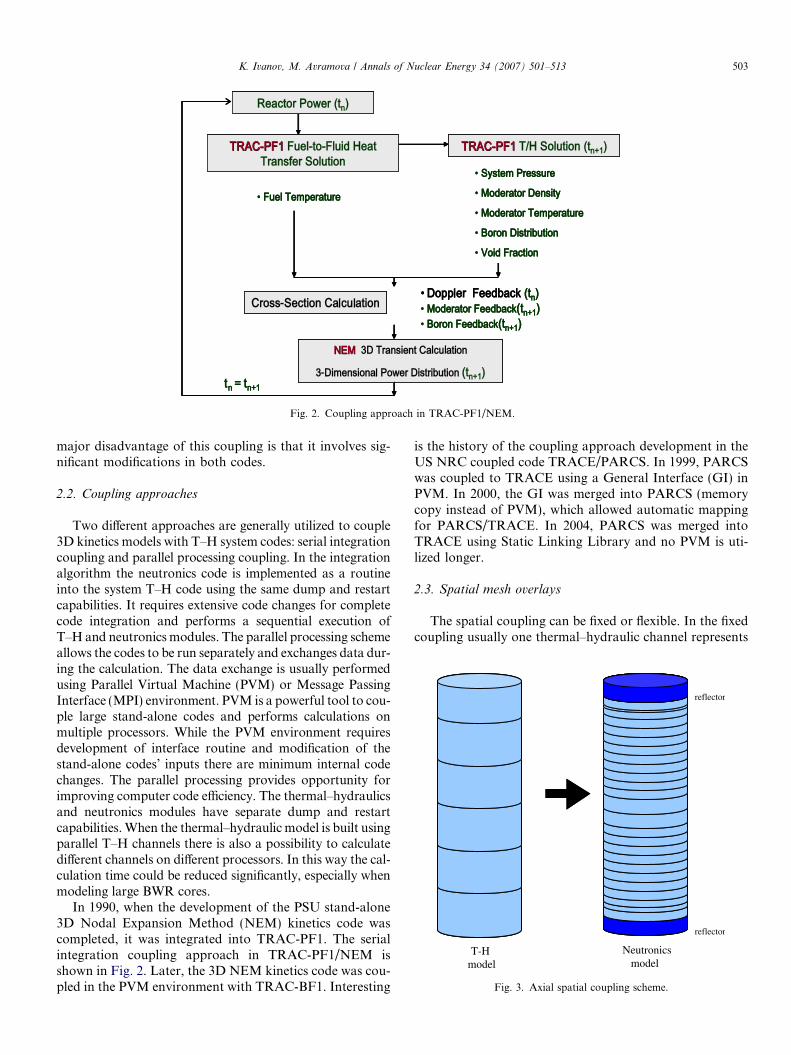
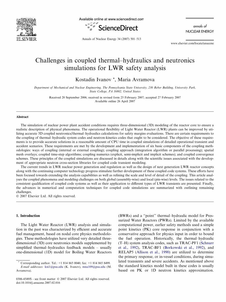
Fig. 2. Coupling approach in TRAC-PF1/NEM.
T-Hmodel
reflector
Neutronicsmodel
reflector
Fig. 3. Axial spatial coupling scheme.
K. Ivanov, M. Avramova / Annals of Nuclear Energy 34 (2007) 501–513 503
major disadvantage of this coupling is that it involves sig-nificant modifications in both codes.
2.2. Coupling approaches
Two different approaches are generally utilized to couple3D kinetics models with T–H system codes: serial integrationcoupling and parallel processing coupling. In the integrationalgorithm the neutronics code is implemented as a routineinto the system T–H code using the same dump and restartcapabilities. It requires extensive code changes for completecode integration and performs a sequential execution ofT–H and neutronics modules. The parallel processing schemeallows the codes to be run separately and exchanges data dur-ing the calculation. The data exchange is usually performedusing Parallel Virtual Machine (PVM) or Message PassingInterface (MPI) environment. PVM is a powerful tool to cou-ple large stand-alone codes and performs calculations onmultiple processors. While the PVM environment requiresdevelopment of interface routine and modification of thestand-alone codes’ inputs there are minimum internal codechanges. The parallel processing provides opportunity forimproving computer code efficiency. The thermal–hydraulicsand neutronics modules have separate dump and restartcapabilities. When the thermal–hydraulic model is built usingparallel T–H channels there is also a possibility to calculatedifferent channels on different processors. In this way the cal-culation time could be reduced significantly, especially whenmodeling large BWR cores.
In 1990, when the development of the PSU stand-alone3D Nodal Expansion Method (NEM) kinetics code wascompleted, it was integrated into TRAC-PF1. The serialintegration coupling approach in TRAC-PF1/NEM isshown in Fig. 2. Later, the 3D NEM kinetics code was cou-pled in the PVM environment with TRAC-BF1. Interesting
is the history of the coupling approach development in theUS NRC coupled code TRACE/PARCS. In 1999, PARCSwas coupled to TRACE using a General Interface (GI) inPVM. In 2000, the GI was merged into PARCS (memorycopy instead of PVM), which allowed automatic mappingfor PARCS/TRACE. In 2004, PARCS was merged intoTRACE using Static Linking Library and no PVM is uti-lized longer.
2.3. Spatial mesh overlays
The spatial coupling can be fixed or flexible. In the fixedcoupling usually one thermal–hydraulic channel represents
504 K. Ivanov, M. Avramova / Annals of Nuclear Energy 34 (2007) 501–513
one neutronics assembly, while in the flexible coupling theuser can specify the mapping schemes. In the latter one hasto trade accuracy versus efficiency and capabilities, whichreally depends on the nature of transient to be analyzed.Spatial mesh overlays (spatial coupling schemes) dependalso on the type of core thermal–hydraulic model. Thereare two types of models – core multi-channel model (using1D parallel channels to represent a BWR core) and 3D ves-sel/core thermal–hydraulic model (to represent a PWRcore). The development of appropriate nodalization andmapping schemes between thermal–hydraulics core model,heat-structure/rod model, and neutronics model is veryimportant and needs to be done in both axial directionand radial plane as illustrated in Figs. 3–6. Fig. 3 providesan example of axial coupling scheme in which several axialneutronics nodes are mapped to a T–H axial node.
Choosing proper spatial mesh overlays for given tran-sient to provide accurate solutions in a reasonable time isa challenging task. The exact detailed mapping providesbetter spatial resolution in coupled calculations. However,this refinement requires significant computationalresources even when one takes advantage of recent pro-gress in computer technology. The computer requirements
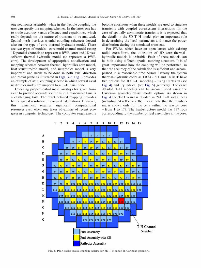
Fig. 4. PWR radial spatial coupling scheme f
become enormous when these models are used to simulatetransients with coupled core/system interactions. In thecase of spatially asymmetric transients it is expected thatthe details in the 3D T–H model play an important rolein determining the local parameters and hence the powerdistribution during the simulated transient.
For PWRs, which have an open lattice with existingradial cross-flows, the utilization of 3D core thermal–hydraulic models is desirable. Each of these models canbe built using different spatial meshing structure. It is ofgreat importance how the coupling will be performed, sothat the accuracy of the calculation is sufficient and accom-plished in a reasonable time period. Usually the systemthermal–hydraulic codes as TRAC-PF1 and TRACE havetwo options for 3D T–H modeling – using Cartesian (seeFig. 4) and Cylindrical (see Fig. 5) geometry. The exactdetailed T–H modeling can be accomplished using theCartesian geometry vessel model option. As shown inFig. 4 the T–H vessel is divided in 241 T–H radial cells(including 64 reflector cells). Please note that the number-ing is shown only for the cells within the reactor core– from 1 to 177. The heat-structure model has 177 rodscorresponding to the number of fuel assemblies in the core.
or 3D T–H model in Cartesian geometry.
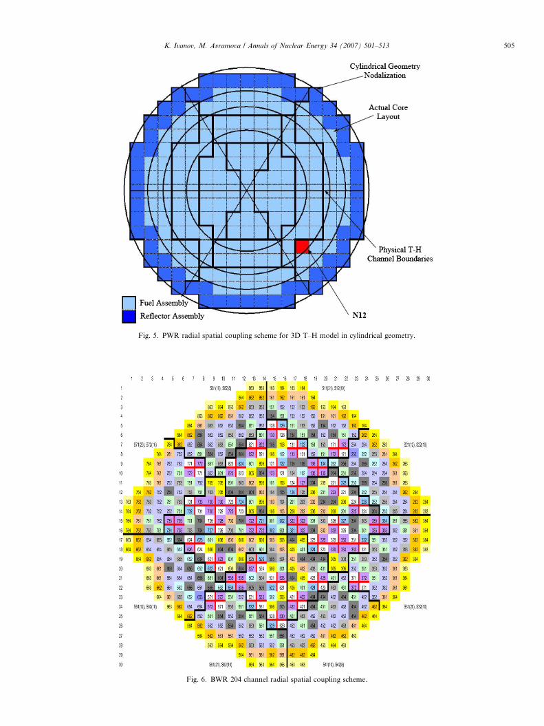
Fig. 5. PWR radial spatial coupling scheme for 3D T–H model in cylindrical geometry.
Fig. 6. BWR 204 channel radial spatial coupling scheme.
K. Ivanov, M. Avramova / Annals of Nuclear Energy 34 (2007) 501–513 505
506 K. Ivanov, M. Avramova / Annals of Nuclear Energy 34 (2007) 501–513
An example of the T–H model of vessel component built incylindrical geometry is shown in Fig. 5. The neutronicscore and reflector regions are mapped in radial plane to24 T–H cells constructed by 4 rings and 6 azimuthal sec-tors. The Cartesian option matches better geometricallythe neutronics core model especially when each neutronicsassembly is coupled directly to a thermal–hydraulic cell andheat structure in both radial and axial direction. This exactdetailed mapping provides better spatial resolution in thecoupled calculations. However, such detail requires signif-icant computational resources. The computer requirementsbecome enormous when these models are used to simulatetransients with coupled core/system interactions. In thecase of spatially asymmetric transients it is expected thatthe detail of mapping of the 3D thermal–hydraulic modelto the core neutronics model plays great role in determin-ing the local parameters and hence the power distributionduring the simulated transient.
The performed sensitivity studies on spatial mesh over-lays for PWR Rod Ejection Accident (REA) analysis(Todorova and Ivanov, 2001) suggested that only the localrefinement of the Doppler (fuel temperature) feedbackmodel does not necessarily improve accuracy of the results.It was shown that the REA simulations are sensitive to thespatial coupling schemes especially in radial plane. Whilethe impact of neutronics mesh refinement is well known,recently it has been found that the local predictions as wellas the global predictions are very sensitive to thermal–hydraulic refinement. The obtained results indicate thatthe T–H feedback phenomenon is non-linear and cannotbe separated even in REA analysis, where the Dopplerfeedback plays a dominant role. These conclusions havebeen reinforced by the performed comparative analysis ofPWR Main Steam Line Break (MSLB) results with the3D core thermal–hydraulic models (Ivanov et al., 2003).The obtained results indicated that the details and geome-try approximation of the core thermal–hydraulics can bean important source of deviations for local parameters,especially for the relative power and fuel temperature dis-tribution in the vicinity of the stuck rod. During the courseof the MSLB transient, a power spike is seen at the positionof the stuck rod. However, in the coarse-mesh model thisassembly is averaged with several of the surroundingassemblies while mapping the neutronics model to the ther-mal–hydraulics model. This has a significant effect ofunderestimating the feedback in this part of the core. Onthe other hand, the detailed model more accurately predictsthe feedback (as a result of the better spatial feedback res-olution), and therefore, the relative power shape and localsafety parameters near the stuck rod. Refinement in theneutronics or heat-structure model does not impact thetotal power transient evolution during the MSLBsimulation.
BWR core contains a large number of fuel assemblies(usually around 800). The exact detailed coupled T–Hand neutronics modeling of such core requires significantcomputational resources. Thus, there is a great interest in
optimization of coupled neutronics/thermal–hydraulic cal-culations. Computational costs could be reduced when col-lapsing similar assemblies into a single T–H channel whilekeeping the detailed neutronics modeling. On the otherhand collapsing the number of T–H channels smoothesthe power distribution and the resultant reactivity feed-back. Finding an optimal number of T–H channels helpsto obtain a balance between the accuracy and CPU time.When mapping neutronics assemblies to thermal–hydraulicchannels usually different rules have to be followed. Forexample, usually similar neutronics assemblies in terms oftheir design are mapped in one channel. This average chan-nel is built based on neutronics and thermal–hydraulicinformation obtained from a core simulator code thataccounts for steady-state core thermal–hydraulicconditions.
Some of the characteristics used to lump together severalneutronics assemblies to one thermal–hydraulic channelare the relative power, coolant flow, void distribution, typeof bundle throttling (orificing), type of fuel (enrichment),burnup, etc. Example of such radial spatial couplingscheme is given in Fig. 6 where 645 neutronics assembliesare mapped to 204 T–H channels. Another rule when per-forming such mapping is to keep core symmetry. Usualapproach is to rank the fuel assemblies according to theirinitial steady state power level, which is obtained from alicensed core simulator, and classify them into groups keep-ing power range as narrow as possible. This approach isknown as ‘‘power flattering’’ mapping. Sensitivity studieshave shown that the steady state analysis is sufficient todesign a suitable T–H model for BWR transients (Ivanovet al., 2004). Mapping non-identical assemblies, in termsof initial power level, to a single T–H channel smoothesthe power distribution and the resultant reactivity feed-back. Decreasing the number of channels leads to overesti-mation of local parameters as demonstrated by thecomparison of normalized radial power distribution. Thedevelopment of the spatial mesh overlays for BWR stabil-ity analysis requires a more sophisticated approach, basedon a modal analysis method, especially in case of the regio-nal instability analysis. The mapping of thermal–hydraulicchannels is performed considering not only the powerpeaks, orifice sizes and thermal hydraulic characteristicsbut also the neutron flux fundamental, first azimuthaland higher modes during the calculation of initial steadystate point.
2.4. Coupled time-step algorithms
The temporal coupling and synchronization is veryimportant since the neutron-kinetics and thermal–hydrau-lics codes usually have their own time-step selection algo-rithms. The easiest and the most straightforwardtechnique is to select one to be used (for example the ther-mal–hydraulics time-step selection algorithm) and makethe size of neutronics step equal to the size of the T–Htime-step size. However, such approach may lead to not

K. Ivanov, M. Avramova / Annals of Nuclear Energy 34 (2007) 501–513 507
accurate predictions of the time dependent power behaviorin some fast transients where local power and flux distribu-tions change significantly. For example, originally the con-vergence criteria in TRAC-PF1 did not account for therelative local neutronics changes. During a transient,TRAC-PF1 calculates the time step size based on the ther-mal–hydraulic conditions and total power variations in theframework of user specified limits. Additional interfaceswere built into the coupled code TRAC-PF1/NEM and avariable time-step control algorithm for the 3D kineticsand proper meshing scheme of this algorithm with thetime-step selection algorithm from fluid-dynamic solutionwas implemented (Ivanov and Baratta, 1999). The numer-ics and logic of the meshing scheme are similar to those forthe PK option but account for both global reactor powerand local neutronics changes. Another example is the mul-tiple time-step marching scheme, implemented in theTRAC-BF1/NEM calculation (Solis et al., 2002). Thisscheme allows TRAC-BF1 solution to march several stepswhile NEM only marches one large time step. For the cou-pled TRAC-BF1/NEM code a 3D kinetics variable time-step algorithm has been also developed and implementedtogether with a meshing scheme with the thermal–hydrau-lic time-step selection algorithm. The kinetics algorithmhas an automatic time-step control procedure that moni-tors the temporal changes (global – total power and local– neutron flux) during a given time step and adjusts thetime-step size automatically. For any successive time inte-gration step, it is required that the maximum change besmaller than a user-specified tolerance e (eG – global, setupto limit global power change to 1% per time step and eL –local, setup to limit local flux change to 10% per time step).The global and local changes are calculated by evaluatingthe first derivative in time of the monitored variables(power and flux). The rate of accumulation of the globalchange (deG/dt) is calculated in L2 norm while the rate ofaccumulation of local change is calculated in L1 norm.The required kinetics time-step size is determined asfollows:
T KG ¼
eG
deG
dt
; T KL ¼
eL
deL
dt
; T Kestimate ¼ min T K
G; TKL
� �P T K
min
T Kmin is equal to the thermal–hydraulic time-step size.
T Kfinal ¼ min T K
estimate; TKmax
� �and T K
max – specified by theuser.
2.5. Coupling numerics
The coupling numerical schemes of neutronics to ther-mal–hydraulics models can be classified by three types– explicit, semi-implicit, and implicit schemes. The classi-fication is based on timing of exchange of the neutronicsand thermal–hydraulics information. The thermal–hydrau-lics model (consisting of hydraulics model and heat struc-ture model) computes new coolant and fuel propertiesand sends some or all of the following parameters to
the neutronics model – moderator temperature, vaporand liquid densities, void fraction, boron concentration,and average, centerline, and surface fuel temperatures.The T–H model uses neutronics power as heat sourcefor conduction calculations. The neutronics model usescoolant/moderator and fuel properties to update macro-scopic cross-sections based on local node conditions.After that it computes 3D flux and power distributionsand sends node-wise power distribution to the thermal–hydraulic model. For example TRAC-PF1/NEM employsan improved semi-implicit neutronics/thermal–hydrauliccoupling scheme. The 3D transient NEM model calculatesthe present time-step nodal power distribution usingcross-section-dependent feedback parameters based onpresent time-step fluid conditions and previous time-stepfuel-rod temperatures.
The major drawback of the current numerical couplingschemes is that they sequentially solve coupled fields using‘‘marching’’ methods, which restrict the time-step size andtake considerable CPU time to converge coupled calcula-tions for each time step. Studies are being performed atPSU to investigate possibility to solve coupled fields simul-taneously, and thereby to increase the time-step size.
2.6. Coupled convergence schemes
Numerical studies on the convergence of the coupledTRAC-PF1/NEM calculations for the TMI-1 NPP powerupgrade MSLB and REA analyses have resulted in anoptimized coupled convergence scheme (Ivanov andBaratta, 1999). TRAC-PF1/NEM simulations involve rig-orous, full-core, 3D neutronics and thermal–hydraulicmodels as well as one-dimensional treatment of the reac-tor coolant system. The developed convergence scheme isan extension of coupled numerical techniques to the sys-tem safety codes. When the solution of the coupled simu-lations is achieved in a loosely coupled fashion, eachcalculation (neutronics and thermal–hydraulics) is fullyconverged based on only an estimate. As a result, thesolution is unstable, the intermediate results oscillate,and a longer time is required for convergence of the cou-pled calculations. When applying an alternative approacha more simultaneous convergence of the thermal–hydrau-lics and the neutronics solutions is achieved, while thelocal fission source is not fully converged (in regard tothe standard tight criteria) during each thermal–hydrauliciteration. This scheme allows a saving of up to 50% incomputation time needed for different transient scenariosimulations.
3. Cross-section modeling for coupled calculations
The need of a more accurate method of modeling cross-section variations for off-nominal core conditions is becom-ing an important issue with the increased use of coupled 3Dneutronics/T–H transient simulations. In reactor core anal-ysis condensed few-group 2D cross-section sets are used as

FT
MT
Fig. 7b. Areas of inaccurate cross-section modeling using the polynomialfitting procedure.
508 K. Ivanov, M. Avramova / Annals of Nuclear Energy 34 (2007) 501–513
input data. The amount of few-group cross-section data,which is necessary for steady state, depletion and transientanalysis, is significant. The cross-section modeling for cou-pled 3D simulations is based on the data generated in theso-called base and branch calculations using a lattice phys-ics code, and assembled into a cross-section library. Thedeveloped in this way cross-section history and instanta-neous dependence models are based on burnup and localfeedback parameters (i.e. fuel temperature, moderator den-sity, moderator temperature, void, and boron concentra-tion). The T–H code coupled with the neutronicssimulator calculates these feedback parameters. Changingeach of the parameters one at a time develops the instanta-neous cross-section dependences. The typical dependenceof a cross-section on a particular parameter over a largerange of values exhibits a non-linear behavior. The interde-pendence of cross-sections can be seen when two parame-ters are varied at once. The cross-sections generated inthis way are called cross-terms and they have to be takeninto account in transient analysis since they are actualpoints on the curved surface. However, the standard tech-niques such as the polynomial fitting procedure (usuallybased on Taylor expansions), and multi-level tables donot take or take partially these cross-terms into account.Since these methods do not model properly cross-termdependencies on local feedback parameters they are espe-cially inaccurate for transients where large departures fromnominal conditions exist, i.e. these procedures becomemore inaccurate as the parameter variations get fartheraway from average conditions.
Fig. 7a shows the typical calculation points necessary todevelop the cross-section derivatives used in the polyno-mial fitting procedure. For simplicity only two feedbackparameters are shown, fuel temperature (TF) and modera-tor temperature (TM). This method uses a cross-section cal-culation at average conditions, shown as the black dot, as areference value. From the reference value parameter per-turbations are performed to develop cross-sections at dif-ferent conditions, shown by the red dots. In this methodonly one parameter is varied at a time, all other parameterremain at average conditions. Once the new cross-section is
FT
MT( )avg
Mavg
F TT ,Σ
( )1, Mavg
F TTΣ ( )3, Mavg
F TTΣ( )2, Mavg
F TTΣ
( )avgMF TT ,3Σ
( )avgMF TT ,1Σ
( avgMF TT ,2Σ )
Fig. 7a. Calculation cross-section points for the polynomial fittingprocedure.
known along with the magnitude of the individual param-eter variation a derivative can be constructed, which is useddirectly in the polynomial equation. Using these derivativesalong with the average cross-sections, a cross-section canbe calculated at any reactor condition. The most significantproblem with this procedure is that it becomes more inac-curate as the parameter variations get farther away fromthe average (nominal) conditions. Fig. 7b shows the areaswhere the polynomial fitting procedure becomes inaccu-rate, shown as the blue hashes.1 The increased inaccuracyof the cross-sections calculated in these regions is moreimportant in transient analysis where parameter variationsextend into these regions. The multi-level tables’ cross-sec-tion parameterization attempts to model the cross-sectioncross-term dependence involving an approximate type ofcross-section representation. Each cross-section can beevaluated as a summation of base and partial values. Themodel tries to account for the cross-term dependence byusing separate partial cross-sections for different feedbackeffects. While the model is an improvement over the poly-nomial fitting procedure it is limited to small perturbations.
To fix the inaccuracies of the above-described proce-dures PSU has developed a sophisticated unique cross-sec-tion representation methodology for 3D coupled transientcalculations (Watson and Ivanov, 2002). The method notonly uses the cross-sections at average (nominal) condi-tions but also uses the cross-term cross-sections as it canbe seen in Fig. 8. As mentioned above, the cross-termcross-sections are cross-sections calculated by varying twoor more parameters at the same time. These cross-sectionsare then tabulated in N-dimensional tables. The N-dimen-sional tables are then interpolated for the appropriatecross-section value. The tabulated cross-sections com-pletely encompass the full range of conditions (nominaland off-nominal) that may be present during the initial
1 For interpretation of color in Fig. 7b, the reader is referred to the webversion of this article.
FT
MT( )avg
Mavg
F TT ,Σ
( )21 , MF TTΣ ( )11 , MF TTΣ ( )31 , MF TTΣ
( )33 , MF TTΣ( )13 , MF TTΣ( )23 , MF TTΣ
( )22 , MF TTΣ ( )12 , MF TTΣ ( )32 , MF TTΣ
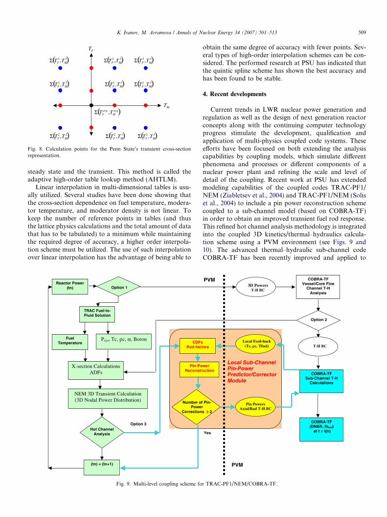
Fig. 8. Calculation points for the Penn State’s transient cross-sectionrepresentation.
K. Ivanov, M. Avramova / Annals of Nuclear Energy 34 (2007) 501–513 509
steady state and the transient. This method is called theadaptive high-order table lookup method (AHTLM).
Linear interpolation in multi-dimensional tables is usu-ally utilized. Several studies have been done showing thatthe cross-section dependence on fuel temperature, modera-tor temperature, and moderator density is not linear. Tokeep the number of reference points in tables (and thusthe lattice physics calculations and the total amount of datathat has to be tabulated) to a minimum while maintainingthe required degree of accuracy, a higher order interpola-tion scheme must be utilized. The use of such interpolationover linear interpolation has the advantage of being able to
Reactor Power (tn)
TRAC Fuel-to-Fluid Solution
FuelTemperature
Psys, Tc, ρc, α, Boron
X-section CalculationsADFs
NEM 3D Transient Calculation (3D Nodal Power Distribution)
Option 1
Hot Channel Analysis
CDFsRod-fac
Pin-PoReconstr
Number oPowe
Correction
(tn) = (tn+1)
Option 3
Fig. 9. Multi-level coupling scheme fo
obtain the same degree of accuracy with fewer points. Sev-eral types of high-order interpolation schemes can be con-sidered. The performed research at PSU has indicated thatthe quintic spline scheme has shown the best accuracy andhas been found to be stable.
4. Recent developments
Current trends in LWR nuclear power generation andregulation as well as the design of next generation reactorconcepts along with the continuing computer technologyprogress stimulate the development, qualification andapplication of multi-physics coupled code systems. Theseefforts have been focused on both extending the analysiscapabilities by coupling models, which simulate differentphenomena and processes or different components of anuclear power plant and refining the scale and level ofdetail of the coupling. Recent work at PSU has extendedmodeling capabilities of the coupled codes TRAC-PF1/NEM (Ziabletsev et al., 2004) and TRAC-PF1/NEM (Soliset al., 2004) to include a pin power reconstruction schemecoupled to a sub-channel model (based on COBRA-TF)in order to obtain an improved transient fuel rod response.This refined hot channel analysis methodology is integratedinto the coupled 3D kinetics/thermal–hydraulics calcula-tion scheme using a PVM environment (see Figs. 9 and10). The advanced thermal–hydraulic sub-channel codeCOBRA-TF has been recently improved and applied to
tors
wer uction
f Pin-r s ≥ 2
Local Feed-back (Tc, ρc, Tfuel)
Pin PowersAxial/Rad T-H BC
COBRA-TFVessel/Core Fine
Channel T-H Analysis
Option 2
T-H BC
COBRA-TFSub-Channel T-H
Calculations
COBRA-TF(DNBR, Hfuel)
at t = t(n)
3D PowersT-H BC
Local Sub-Channel Pin-Power Predictor/CorrectorModule
Yes
PVM
PVM
r TRAC-PF1/NEM/COBRA-TF.
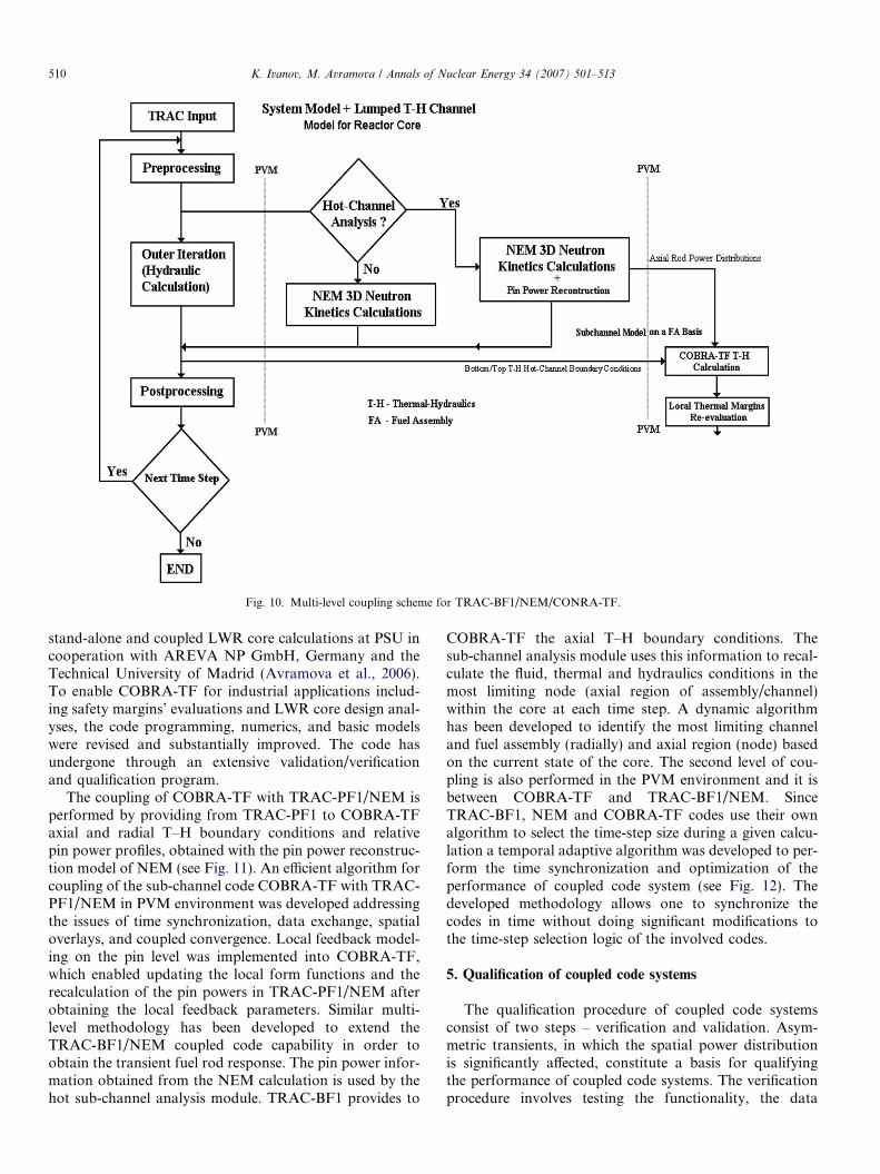
Fig. 10. Multi-level coupling scheme for TRAC-BF1/NEM/CONRA-TF.
510 K. Ivanov, M. Avramova / Annals of Nuclear Energy 34 (2007) 501–513
stand-alone and coupled LWR core calculations at PSU incooperation with AREVA NP GmbH, Germany and theTechnical University of Madrid (Avramova et al., 2006).To enable COBRA-TF for industrial applications includ-ing safety margins’ evaluations and LWR core design anal-yses, the code programming, numerics, and basic modelswere revised and substantially improved. The code hasundergone through an extensive validation/verificationand qualification program.
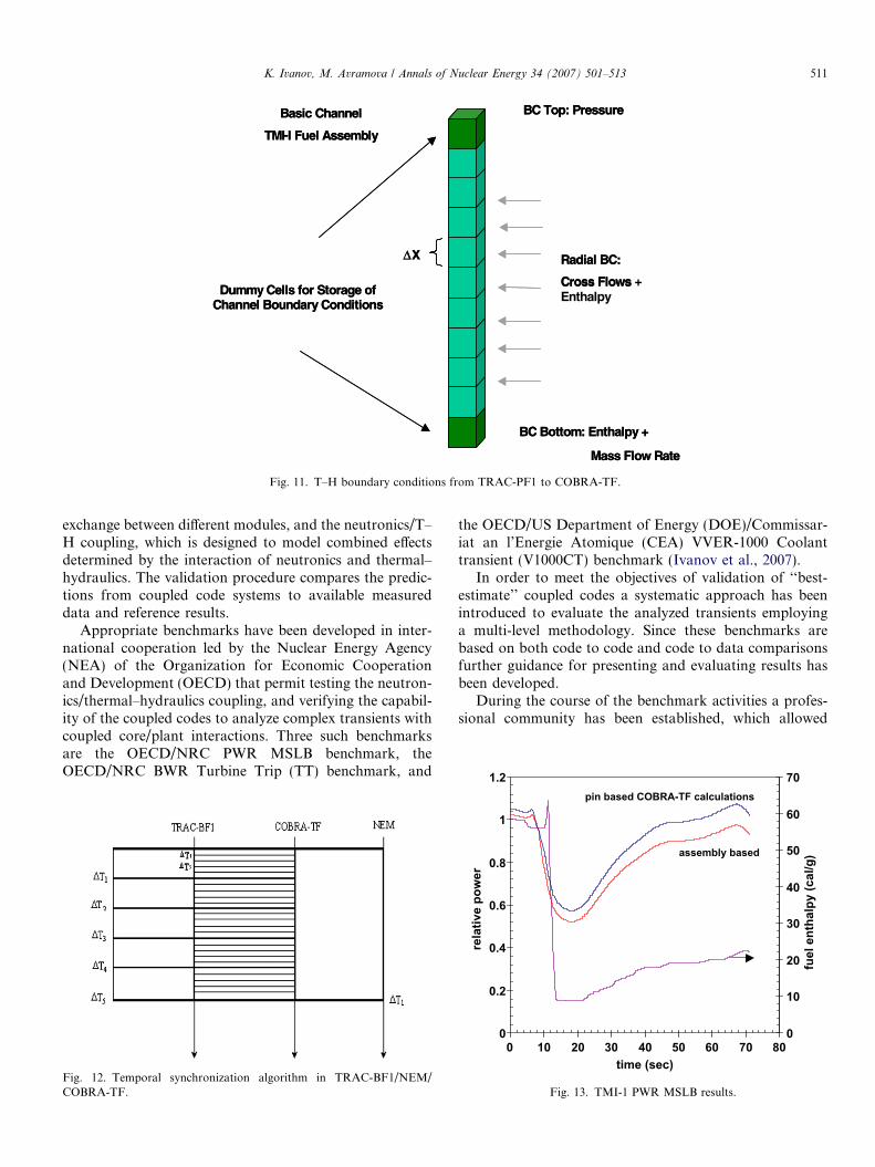
The coupling of COBRA-TF with TRAC-PF1/NEM isperformed by providing from TRAC-PF1 to COBRA-TFaxial and radial T–H boundary conditions and relativepin power profiles, obtained with the pin power reconstruc-tion model of NEM (see Fig. 11). An efficient algorithm forcoupling of the sub-channel code COBRA-TF with TRAC-PF1/NEM in PVM environment was developed addressingthe issues of time synchronization, data exchange, spatialoverlays, and coupled convergence. Local feedback model-ing on the pin level was implemented into COBRA-TF,which enabled updating the local form functions and therecalculation of the pin powers in TRAC-PF1/NEM afterobtaining the local feedback parameters. Similar multi-level methodology has been developed to extend theTRAC-BF1/NEM coupled code capability in order toobtain the transient fuel rod response. The pin power infor-mation obtained from the NEM calculation is used by thehot sub-channel analysis module. TRAC-BF1 provides to
COBRA-TF the axial T–H boundary conditions. Thesub-channel analysis module uses this information to recal-culate the fluid, thermal and hydraulics conditions in themost limiting node (axial region of assembly/channel)within the core at each time step. A dynamic algorithmhas been developed to identify the most limiting channeland fuel assembly (radially) and axial region (node) basedon the current state of the core. The second level of cou-pling is also performed in the PVM environment and it isbetween COBRA-TF and TRAC-BF1/NEM. SinceTRAC-BF1, NEM and COBRA-TF codes use their ownalgorithm to select the time-step size during a given calcu-lation a temporal adaptive algorithm was developed to per-form the time synchronization and optimization of theperformance of coupled code system (see Fig. 12). Thedeveloped methodology allows one to synchronize thecodes in time without doing significant modifications tothe time-step selection logic of the involved codes.
5. Qualification of coupled code systems
The qualification procedure of coupled code systemsconsist of two steps – verification and validation. Asym-metric transients, in which the spatial power distributionis significantly affected, constitute a basis for qualifyingthe performance of coupled code systems. The verificationprocedure involves testing the functionality, the data
ΔX
Dummy Cells for Storage of Channel Boundary Conditions
Radial BC:
Cross Flows
BC Top: Pressure
BC Bottom: Enthalpy +
Mass Flow Rate
Basic Channel
TMI-I Fuel Assembly
ΔX
Dummy Cells for Storage of Channel Boundary Conditions
Radial BC:
Cross Flows + Enthalpy
BC Top: Pressure
BC Bottom: Enthalpy +
Mass Flow Rate
Basic Channel
TMI-I Fuel Assembly
Fig. 11. T–H boundary conditions from TRAC-PF1 to COBRA-TF.
1.2 70
K. Ivanov, M. Avramova / Annals of Nuclear Energy 34 (2007) 501–513 511
exchange between different modules, and the neutronics/T–H coupling, which is designed to model combined effectsdetermined by the interaction of neutronics and thermal–hydraulics. The validation procedure compares the predic-tions from coupled code systems to available measureddata and reference results.
Appropriate benchmarks have been developed in inter-national cooperation led by the Nuclear Energy Agency(NEA) of the Organization for Economic Cooperationand Development (OECD) that permit testing the neutron-ics/thermal–hydraulics coupling, and verifying the capabil-ity of the coupled codes to analyze complex transients withcoupled core/plant interactions. Three such benchmarksare the OECD/NRC PWR MSLB benchmark, theOECD/NRC BWR Turbine Trip (TT) benchmark, and
Fig. 12. Temporal synchronization algorithm in TRAC-BF1/NEM/COBRA-TF.
the OECD/US Department of Energy (DOE)/Commissar-iat an l’Energie Atomique (CEA) VVER-1000 Coolanttransient (V1000CT) benchmark (Ivanov et al., 2007).
In order to meet the objectives of validation of ‘‘best-estimate’’ coupled codes a systematic approach has beenintroduced to evaluate the analyzed transients employinga multi-level methodology. Since these benchmarks arebased on both code to code and code to data comparisonsfurther guidance for presenting and evaluating results hasbeen developed.
During the course of the benchmark activities a profes-sional community has been established, which allowed
0
0.2
0.4
0.6
0.8
1
0 10 20 30 40 50 60 70 80time (sec)
rela
tive
pow
er
0
10
20
30
40
50
60fu
el e
ntha
lpy
(cal
/g)assembly based
pin based COBRA-TF calculations
Fig. 13. TMI-1 PWR MSLB results.

1
4
7 S11
S16
S210
1
2
3
4
5
6
7
8
9
Rel
ativ
e P
ower
"Laguna Verde" CRDA Benchmark 2-D Radial Power Distribution - time = 5.0 sec
512 K. Ivanov, M. Avramova / Annals of Nuclear Energy 34 (2007) 501–513
carrying out in-depth discussions of different aspects con-sidered in the validation process of the coupled codes. Thispositive output has certainly advanced the state-of-the-artin the area of coupling research.
6. Application of coupled code systems
The application of coupled 3D code systems to NPPsafety analysis can be performed in both ‘‘best estimate’’and bounding manners. It brings the ability to evaluatenew issues connected with extended cycles, higher dis-charge burnups, and power upgrades. The improved anal-ysis helps to reduce operation and maintenance costs(conservative assumptions of point kinetics can be too lim-iting). The application of coupled code systems requirescorrect initial steady state reproduction and accurate andefficient transient simulation. For example, TRAC-PF1/NEM/COBRA-TF was applied to analysis of the twodesign basis accidents – REA and MSLB – for powerupgrade of TMI-1 NPP. In both calculations the obtained
10
13
16
19
22
S1
S6XY
Fig. 16. BWR Laguna Verde CRDA results.
0
2
4
6
8
10
12
14
16
18
20
0 10 20 30 40 50 60 70 80time (sec)
MD
NB
R
pin based COBRA-TF calculations
FA average
Fig. 14. TMI-1 PWR MSLB results.
8201
0
1000
2000
3000
4000
5000
6000
7000
8000
9000
0 0.1 0.2 0.3time (sec)
rela
tive
po
wer
15
20
25
30
35
40
45
50
fuel
en
thal
py
(cal
/g)
total power
FA based fuelenthalpy
Fine subchannel based fuel enthalpy(local feedbackmodelled)
Fig. 15. TMI-1 PWR REA results.
local (pin-based) results (in terms of fuel enthalpy and min-imum departure to nucleate boiling ratio – MDNBR) arecloser than the global (assembly-based) predictions to thecorresponding critical limits (see Figs. 13–15). This factindicates that the assembly average results tend to underes-timate the accident consequences in terms of local safetymargins. The obtained results demonstrate the importanceof having a capability for local safety evaluations, per-formed simultaneously (on-line) with coupled globalthree-dimensional neutron kinetics/thermal–hydraulic cal-culations. Another example is the application of TRAC-BF1/NEM/COBRA-TF to the Mexican ‘‘Laguna Verde’’1 NPP control rod drop accident (CRDA). Fig. 16 repre-sents the predicted radial power distribution at the end ofthe transient.
7. Conclusions
The current industry environment is characterized by aderegulated power generation market with improved eco-nomics while maintaining high nuclear safety standards.‘‘Best-estimate’’ modeling for reactor system analysisrequires an increased use of coupled 3D neutron-kinetics/T–H system codes to predict realistic safety margins. Inthe case of PWR transient simulations with non-symmetricfeedback effects it is recommended to use 3D T–H modelscoupled with 3D neutronics models. Further, a couplingprocedure between the 3D T–H core model in Cartesiangeometry and 3D T–H vessel model in Cylindrical geome-try is expected to be developed, supplemented by 1D mod-
K. Ivanov, M. Avramova / Annals of Nuclear Energy 34 (2007) 501–513 513
eling of the balance of the plant, when performing morecomplex system transient simulations with 3D kinetics.Future efforts in BWR coupled code calculations shouldbe directed towards developing rules for choosing an opti-mal number of T–H channels, which account for the natureof the transient phenomena, initial power and burnup dis-tributions, and assembly geometry. The remaining chal-lenges are consistent improving coupled methodologies interms of accuracy and efficiency of numerical simulations,and integrating fuel management and safety analysis basedon the same advanced coupled methodologies. In order toapply the coupled code systems to licensing safety analysisof NPPs in a ‘‘best estimate’’ manner uncertainty analysismethods for coupled calculations have to be developedand tested.
References
Allison, C. et al., 1990. RELAP5/MOD3 code manual. NUREG/CR-5535.
Avramova, M., Ivanov, K., Cuervo, D., 2006. Improvements andapplications of COBRA-TF for stand-alone and coupled LWR safetyanalyses. In: Proceedings of PHYSOR-2006 Conference, CD-Rom(Electronic Publication), Vancouver, Canada.
Borkowski, J. et al., 1992. TRAC-BF1: an advanced best-estimatecomputer program for BWR accident analysis. NUREG/CR-4356.
Dias, A. 1997. CORETRAN-01 – theory and numerical analysis. EPRI.Hu, Y., Downar, T., Kozlowski, T., Ivanov, K., Staudenmeier, J., 2006.
Multi-physics coupled code reactor analysis with the US NRC codesystem TRACE/PARCS. In: Proceedings of PHYSOR-2006 Confer-ence, CD-Rom (Electronic Publication), Vancouver, Canada.
Ivanov, K., Baratta, A., 1999. Coupling methodologies for best estimatesafety analysis. In: Proceedings of M&C’99 Conference, vol. 1,Madrid, Spain, pp. 493–502.
Ivanov, K., Todorova, N., Sartori, E., 2003. Using the OECD/NRC PWRMSLB benchmark to study current numerical and computationalissues of coupled calculations. Nuclear Technology 142 (2), 95–115.
Ivanov, K., Olson, A., Sartori, E., 2004. OECD/NRC BWR TTbenchmark as a basis for comprehensive qualification and studyingbest estimate coupled codes. Nuclear Science and Engineering 148 (2),195–207.
Ivanov, K., Sartori, E., Royer, E., Langenbuch, S., Velkov, K., 2007.Validation of coupled thermal–hydraulic and neutronics codes forsafety analysis by international co-operations. Nuclear Technology157 (2), 177–195.
Schnurr, N. et al., 1992. TRAC-PF1/MOD2 code manual. NUREG/CR-5673, LA-12031-M. vol. 2.
Solis, J., Avramova, M., Ivanov, K., 2002. Temporal adaptive algorithmfor TRAC-BF1/NEM/COBRA-TF coupled calculations in BWRsafety analysis. Annals of Nuclear Energy 29, 2127–2141.
Solis, J., Avramova, M., Ivanov, K., 2004. Multi-level methodology inparallel computing environment for evaluating BWR safety parame-ters. Nuclear Technology 146 (3), 267–278.
Thurgood, M. et al., 1983. COBRA/TRAC – a thermal–hydraulic codefor transient analysis of nuclear reactor vessel and primary coolantsystems. NUREG/CR-3046.
Todorova, N., Ivanov, K., 2001. PWR REA sensitivity analysis usingTRAC-PF1/NEM. In: Proceedings of ICONE-9 Conference, CD-Rom (Electronic Publication), Nice, France.
Watson, J., Ivanov, K., 2002. Improved cross-section modeling method-ology for coupled three-dimensional transient calculations. Annals ofNuclear Energy 29, 937–966.
Ziabletsev, D., Avramova, M., Ivanov, K., 2004. Development of PWRintegrated safety analysis methodology using multi-level couplingalgorithm. Nuclear Science and Engineering 148 (3), 414–425.