ch_9_10_11
TRANSCRIPT
1
Chapter 9
Architectural Design

2
Why Architecture?The architecture is not the operational software. The architecture is not the operational software.
Rather, it is a representation that enables a software engineer Rather, it is a representation that enables a software engineer to: to:
(1) (1) analyze the effectiveness of the design to meet to meet requirements, requirements,
(2) (2) consider architectural alternatives at a stage when making at a stage when making design changes is still relatively easy, and design changes is still relatively easy, and
(3) (3) reduce the risks associated with the construction of the associated with the construction of the software.software.

3
Architectural Styles
Each style describes a system category that Each style describes a system category that encompasses: encompasses:
(1) a (1) a set of components (e.g., a database, (e.g., a database, computational modules) that perform a function required computational modules) that perform a function required by a system, by a system,
(2) a (2) a set of connectors that enable “communication, that enable “communication, coordination and cooperation” among components, coordination and cooperation” among components,
(3) (3) constraints that define how components can be that define how components can be integrated to form the system, and integrated to form the system, and
(4) (4) semantic models that enable a designer to that enable a designer to understand the overall properties of a system by understand the overall properties of a system by analyzing the known properties of its constituent parts. analyzing the known properties of its constituent parts.

4
Data-Centered Architecture

5
Data Flow Architecture

6
Call and Return Architecture

7
Layered Architecture

These slides are designed to accompany Software Engineering: A Practitioner’s Approach, 7/e (McGraw-Hill, 2009). Slides copyright 2009 by Roger Pressman. 8
Architectural Design The software must be placed into context
the design should define the external entities
(other systems, devices, people) that the software interacts
with and the nature of the interaction
A set of architectural archetypes should be identified An archetype is an abstraction (similar to a class) that
represents one element of system behavior
The designer specifies the structure of the system by defining and refining software components that implement each archetype

9
Architectural Context
target system: Security Function
uses
uses peershomeowner
Safehome Product
Internet-based system
surveillance function
sensors
control panel
sensors
uses

10
Archetypes
Figure 10.7 UML relationships for SafeHome security function archetypes (adapted from [BOS00])
Controller
Node
communicates with
Detector Indicator

11
Component Structure
SafeHome Executive
External Communication Management
GUI Internet Interface
Function selection
Security Surveillance Home management
Control panel
processing
detector management
alarm processing

12
Refined Component Structure
sensorsensorsensorsensor
sensorsensorsensor
sensor
External Communication Management
GUI Internet Interface
Security
Control
panelprocessing
detector
managementalarm
processing
Keypad processing
CP display functions
scheduler
sensorsensorsensorsensor
phone communication
alarm
SafeHome Executive

13
Analyzing Architectural Design
1. Collect scenarios. 1. Collect scenarios. 2. Elicit requirements, constraints, and environment 2. Elicit requirements, constraints, and environment description. description. 3.3.Describe the architectural styles/patterns that have been Describe the architectural styles/patterns that have been chosen tochosen to address the scenarios and requirements:address the scenarios and requirements:
• • module viewmodule view• • process viewprocess view• • data flow viewdata flow view
4. Evaluate quality attributes by considered each attribute in 4. Evaluate quality attributes by considered each attribute in isolation. isolation. 5.5.Identify the sensitivity of quality attributes to various Identify the sensitivity of quality attributes to various architectural architectural attributes for a specific architectural style. attributes for a specific architectural style. 6.6.Critique candidate architectures (developed in step 3) using Critique candidate architectures (developed in step 3) using thethe sensitivity analysis conducted in step 5.sensitivity analysis conducted in step 5.

14
An Architectural Design Method
"four bedrooms, three baths,lots of glass ..."
customer requirements
architectural design

15
Deriving Program Architecture
ProgramProgramArchitectureArchitecture

16
Partitioning the Architecture“horizontal” and “vertical” partitioning are required

17
Horizontal Partitioning define separate branches of the module hierarchy
for each major function use control modules to coordinate communication
between functions
function 1function 1 function 3function 3
function 2function 2

18
Vertical Partitioning: Factoring design so that decision making and work are
stratified decision making modules should reside at the
top of the architecture
workers
decision-makers

These slides are designed to accompany Software Engineering: A Practitioner’s Approach, 7/e (McGraw-Hill, 2009). Slides copyright 2009 by Roger Pressman. 19
Structured Design
objective: to derive a program architecture that is partitioned
approach: a DFD is mapped into a program architecture the PSPEC and STD are used to indicate the
content of each module
notation: structure chart

20
What is a Component?UML Unified Modeling Language Specification defines a component as OO Object Oriented Component: a component contains a set of collaborating classesConventional Component: a component contains processing logic, the internal data structures that are required to implement the processing logic, and an interface that enables the component to be invoked and data to be passed to it.
Chapter 10

21
OO Component
PrintJ ob
computeJ ob
init iateJ ob
numberOfPages numberOfSides paperType paperWeight
paperSize paperColor magnif ication colorRequirements productionFeatures
collationOptions bindingOptions coverStock bleed priority totalJ obCost
WOnumber
PrintJ ob
computePageCost () computePaperCost ()
computeProdCost () computeTotalJ obCost () buildWorkOrder() checkPriority () passJ obto Production()
elaborated design class<<interface>> computeJ ob
computePageCost ()
computePaperCost () computeProdCost () computeTotalJ obCost ()
<<interface>>
initiateJ ob
buildWorkOrder() checkPriority () passJ obto Production()
design component
numberOfPages
numberOfSides
paperType magnif ication
productionFeatures
PrintJ ob
computeJ obCost()
passJ obtoPrinter()
analysis c lass

22
Conventional Component
ComputePageCost
design component
accessCostsDB
getJ obData
elaborated module
PageCost
in: job size in: color=1, 2, 3, 4 in: pageSize = A, B, C, B out: BPC out: SF
in: numberPages in: numberDocs in: sides= 1, 2 in: color=1, 2, 3, 4 in: page size = A, B, C, B out: page cost
job size ( J S) =
numberPages * numberDocs;lookup base page cost (BPC) --> accessCostsDB (J S, color) ;
lookup size factor ( SF) --> accessCostDB ( J S, color, size)
job complexity factor ( J CF) = 1 + [(sides-1)* sideCost + SF]pagecost = BPC * J CF
getJ obData (numberPages, numberDocs, sides, color, pageSize, pageCost)
accessCostsDB (jobSize, color, pageSize, BPC, SF)computePageCost()

23
Design Guidelines Components
Naming should be established for components that are specified as part of the architectural model and then refined and elaborated as part of the component-level model
InterfacesInterfaces provide important information about communication and collaboration
Dependencies and Inheritanceit is a good idea to model dependencies from left to right and inheritance from bottom (derived classes) to top (base classes).

24
Component Level Design-I Step 1. Identify all design classes that correspond to the
problem domain. Step 2. Identify all design classes that correspond to the
infrastructure domain. Step 3. Elaborate all design classes that are not acquired
as reusable components. Step 3a. Specify message details when classes or
component collaborate. Step 3b. Identify appropriate interfaces for each
component.

25
Component-Level Design-II Step 3c. Elaborate attributes and define data types and
data structures required to implement them. Step 3d. Describe processing flow within each operation in
detail. Step 4. Describe persistent data sources (databases and
files) and identify the classes required to manage them. Step 5. Develop and elaborate behavioral representations
for a class or component. Step 6. Elaborate deployment diagrams to provide
additional implementation detail. Step 7. Factor every component-level design
representation and always consider alternatives.

26
Collaboration Diagram
:ProductionJob
:WorkOrder
:JobQueue
1: buildJob (WOnumber)2: submitJob (WOnumber)

27
Refactoring
PrintJ ob
computeJ ob
initiateJ ob
ProductionJ ob
buildJ ob
submitJ ob
WorkOrder
appropriate attributes
buildWorkOrder ()getJ obDescriiption
J obQueue
appropriate attributes
checkPriority ()
<<interface>> initiateJ ob
passJ obToProduction()
28
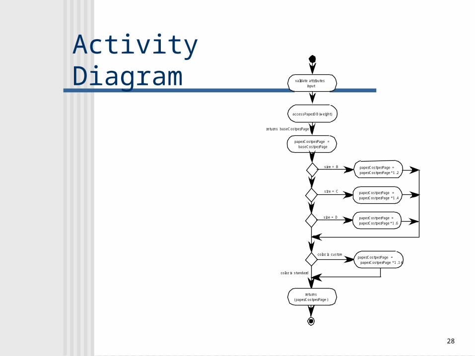
Activity Diagram validate attributes input
accessPaperDB(weight)
returns baseCostperPage
size = B paperCostperPage = paperCostperPage *1 .2
size = C paperCostperPage = paperCostperPage *1 .4
size = D paperCostperPage = paperCostperPage *1 .6
color is custompaperCostperPage = paperCostperPage *1 .1 4
color is standard
paperCostperPage = baseCostperPage
returns( paperCostperPage )

29
Statechart buildingJ obData
entry/ readJ obData() exit/displayJ obData() do/ checkConsistency() include/ dataInput
entry/ computeJ ob exit/ save totalJ obCost
formingJ ob
entry/ buildJ ob exit/ save WOnumber do/
computingJ obCost
submittingJ ob
entry/ submitJ ob exit/initiateJ ob do/ place on J obQueue
behavior within the state buildingJ obData
dataInputCompleted [all data items consistent]/ displayUserOptions
dataInputIncomplete
jobCostAccepted [customer is authorized]/ getElectronicSignature
jobSubmitted [all authorizations acquired]/ printWorkOrder

30
Designing Conventional Components The design of processing logic is governed by
the basic principles of algorithm design and structured programming
The design of data structures is defined by the data model developed for the system
The design of interfaces is governed by the collaborations that a component must effect

31
Algorithm Design
the closest design activity to coding the approach:
review the design description for the component
use stepwise refinement to develop algorithm use structured programming to implement
procedural logic use ‘formal methods’ to prove logic

32
Algorithm Design Model
represents the algorithm at a level of detail that can be reviewed for quality
options: graphical (e.g. flowchart, box diagram) pseudocode (e.g., PDL) ... choice of many
programming language decision table

33
Structured Programming
uses a limited set of logical constructs:uses a limited set of logical constructs: sequencesequence conditionalconditional — — if-then-else, select-caseif-then-else, select-case loopsloops — — do-while, repeat untildo-while, repeat until
leads to more readable, testable codeleads to more readable, testable code
important for achieving high quality, important for achieving high quality, but not enoughbut not enough
can be used in conjunction with ‘proof can be used in conjunction with ‘proof of correctness’of correctness’
34
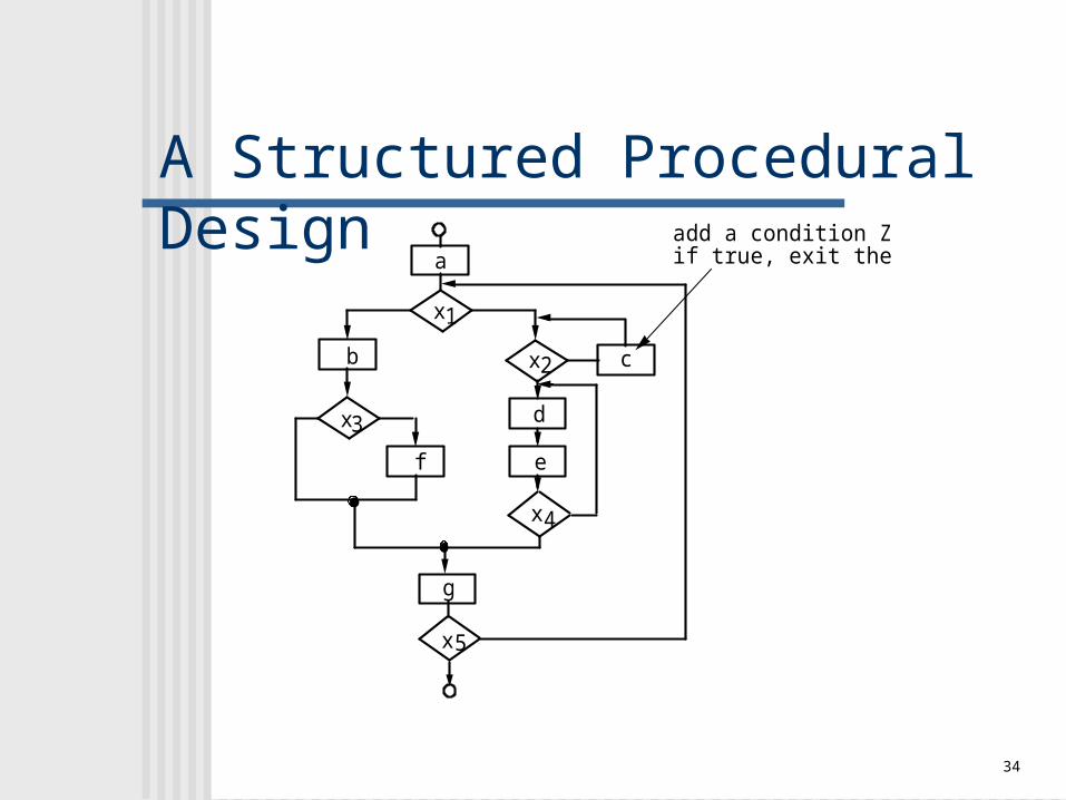
A Structured Procedural Design
a
x1
x2b
3x
4
5
c
d
ef
g
x
x
add a condition Z, if true, exit the program
35
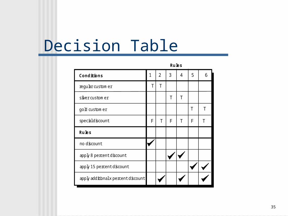
Decision Table
Conditions
regular customer
silver customer
gold customer
special discount
Rules
no discount
apply 8 percent discount
apply 15 percent discount
apply additional x percent discount
T
F
T
T
T
T
T
F
1 3 5 64
F
T T
T
2
Rules

36
Program Design Language (PDL)
if-then-else
if condition x then process a; else process b; endif
PDL
easy to combine with source code machine readable, no need for graphics input graphics can be generated from PDL enables declaration of data as well as procedure easier to maintain

37
Interface Design
Easy to use?Easy to use?
Easy to understand?Easy to understand?
Easy to learn?Easy to learn?
Chapter 11

38
Golden Rules
Place the user in control Reduce the user’s memory load Make the interface consistent

39
Place the User in ControlDefine interaction modes in a way that does Define interaction modes in a way that does not force a user into unnecessary or not force a user into unnecessary or undesired actions. undesired actions.
Provide for flexible interaction. Provide for flexible interaction.
Allow user interaction to be interruptible and Allow user interaction to be interruptible and undoable. undoable.
Streamline interaction as skill levels advance Streamline interaction as skill levels advance and allow the interaction to be customized. and allow the interaction to be customized.
Hide technical internals from the casual user. Hide technical internals from the casual user.
Design for direct interaction with objects that Design for direct interaction with objects that appear on the screen.appear on the screen.

40
Reduce the User’s Memory Load
Reduce demand on short-term memory. Reduce demand on short-term memory.
Establish meaningful defaults. Establish meaningful defaults.
Define shortcuts that are intuitive. Define shortcuts that are intuitive.
The visual layout of the interface should be The visual layout of the interface should be based on a real world metaphor. based on a real world metaphor.
Disclose information in a progressive fashion.Disclose information in a progressive fashion.

41
Make the Interface Consistent
Allow the user to put the current task into a Allow the user to put the current task into a meaningful context. meaningful context.
Maintain consistency across a family of Maintain consistency across a family of applications. applications.
If past interactive models have created user If past interactive models have created user expectations, do not make changes unless expectations, do not make changes unless there is a compelling reason to do so. there is a compelling reason to do so.

42
User Interface Design Models User model — a profile of all end users of
the system Design model — a design realization of the
user model Mental model (system perception) — the
user’s mental image of what the interface is Implementation model — the interface “look
and feel” coupled with supporting information that describe interface syntax and semantics

43
User Interface Design Process

44
Interface Analysis Interface analysis means understanding
(1) the people (end-users) who will interact with the system through the interface;
(2) the tasks that end-users must perform to do their work,
(3) the content that is presented as part of the interface
(4) the environment in which these tasks will be conducted.

45
Interface Design Steps
Using information developed during interface analysis, define interface objects and actions (operations).
Define events (user actions) that will cause the state of the user interface to change. Model this behavior.
Depict each interface state as it will actually look to the end-user.
Indicate how the user interprets the state of the system from information provided through the interface.

These slides are designed to accompany Software Engineering: A Practitioner’s Approach, 7/e (McGraw-Hill, 2009) Slides copyright 2009 by Roger Pressman. 46
Design Evaluation Cyclepreliminary
design
buildprototype #1
interface
evaluationis studied by
designer
designmodifications
are made
buildprototype # n
interface
userevaluate'sinterface
Interface designis complete