ch.8 section views section views and sectional drawings (8.1) visualization of section views (8.1.2)...
Post on 21-Dec-2015
257 views
TRANSCRIPT
Ch.8 Section Views
Section views and sectional drawings (8.1) Visualization of section views (8.1.2) Cutting plane lines and their placement (8.2 &
8.2.1) Section line practices (8.3) Section view types (8.4) Special conventions you need to be familiar with
(8.5)
Objective: Learn how to create section views and
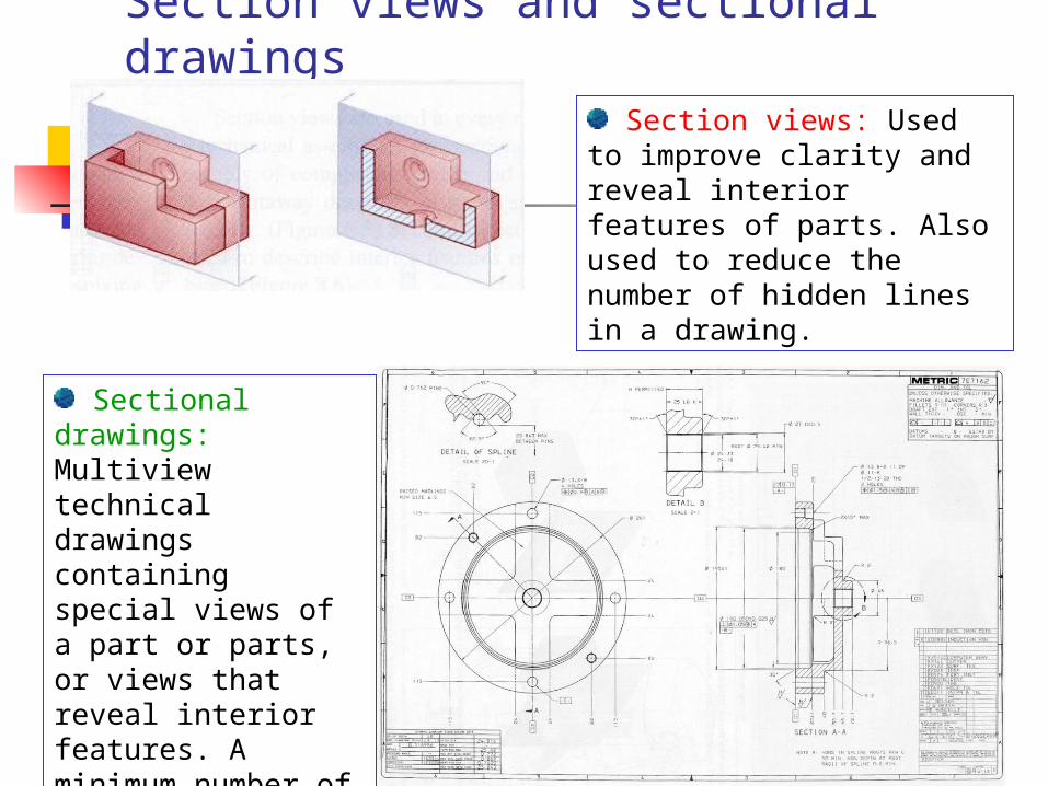
Section views and sectional drawings
Section views: Used to improve clarity and reveal interior features of parts. Also used to reduce the number of hidden lines in a drawing.
Sectional drawings: Multiview technical drawings containing special views of a part or parts, or views that reveal interior features. A minimum number of hidden lines are used.
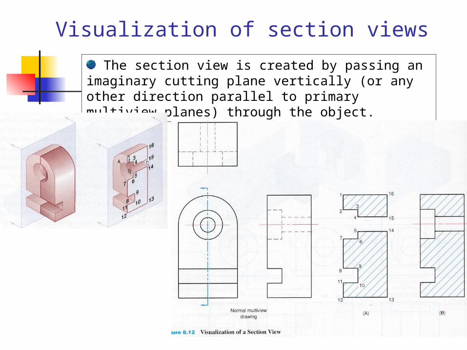
Visualization of section views
The section view is created by passing an imaginary cutting plane vertically (or any other direction parallel to primary multiview planes) through the object.
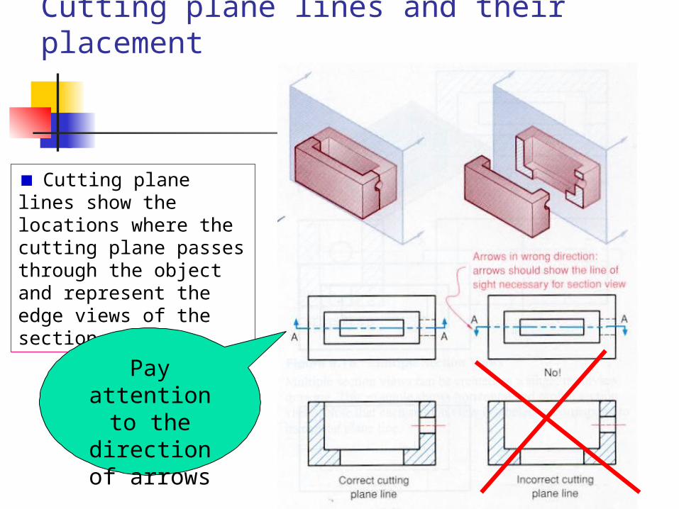
Cutting plane lines and their placement
Cutting plane lines show the locations where the cutting plane passes through the object and represent the edge views of the section views
Pay attention to
the direction of
arrows

Dealing with hidden lines
Hidden lines are usually minimized but can be shown in section views usually to eliminate the need for another view.
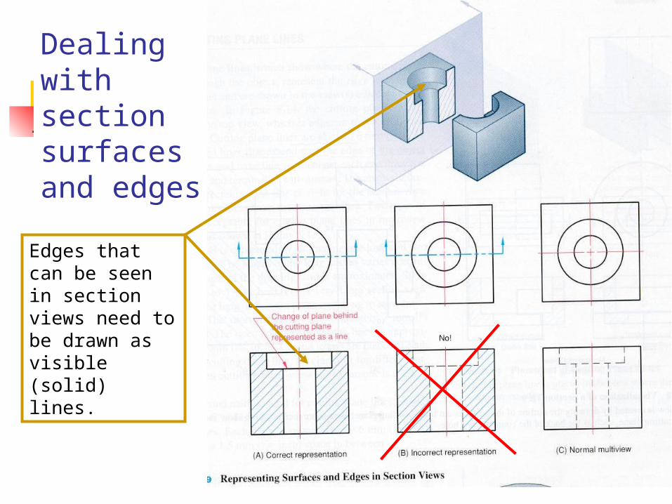
Dealing with section surfaces and edges
Edges that can be seen in section views need to be drawn as visible (solid) lines.
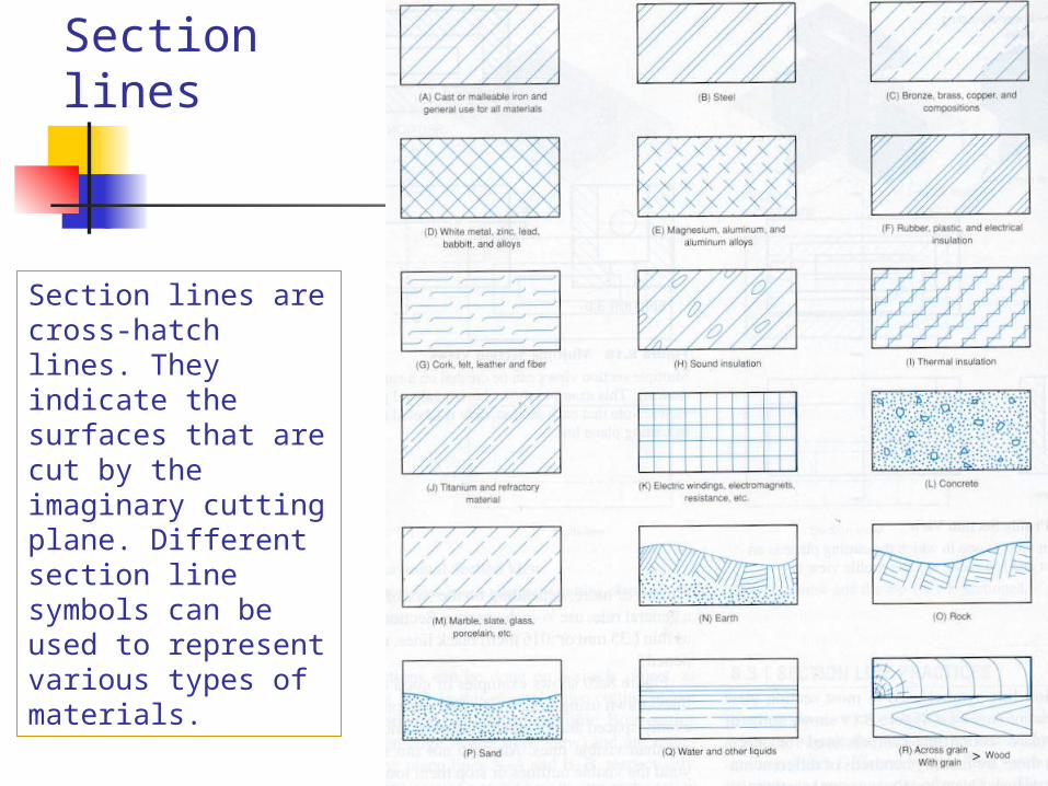
Section lines
Section lines are cross-hatch lines. They indicate the surfaces that are cut by the imaginary cutting plane. Different section line symbols can be used to represent various types of materials.
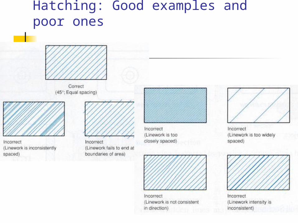
Hatching: Good examples and poor ones

Special Cases
But, remember to place dimensions outside of the object as much as possible.
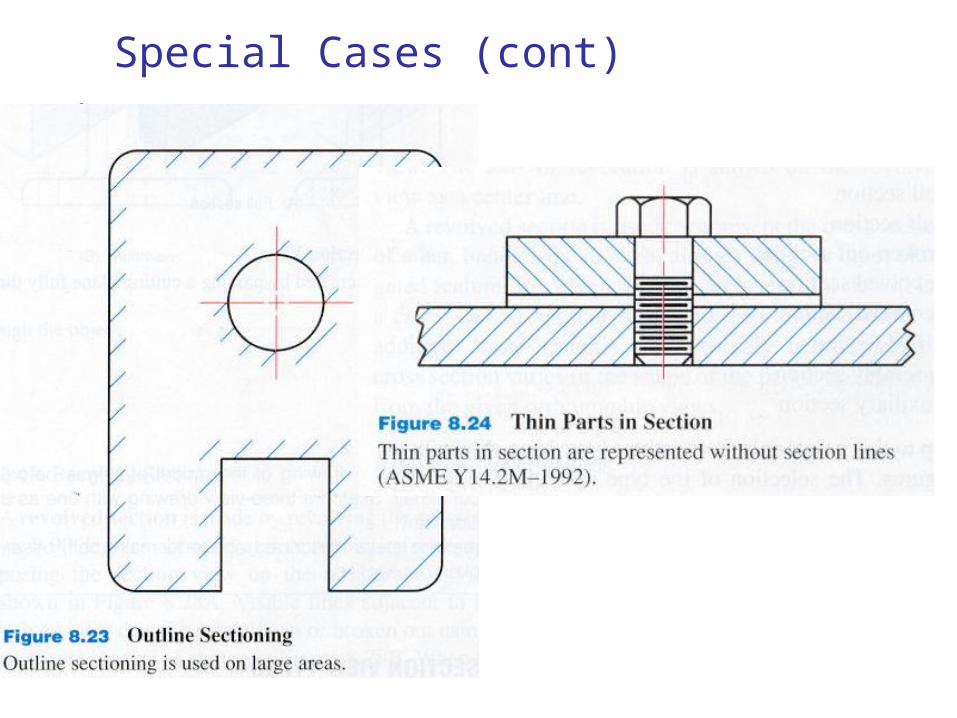
Special Cases (cont)
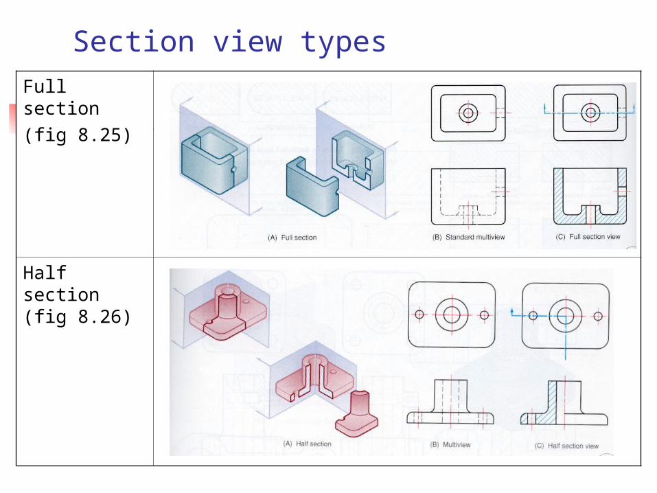
Section view typesFull section (fig 8.25)
Half section (fig 8.26)
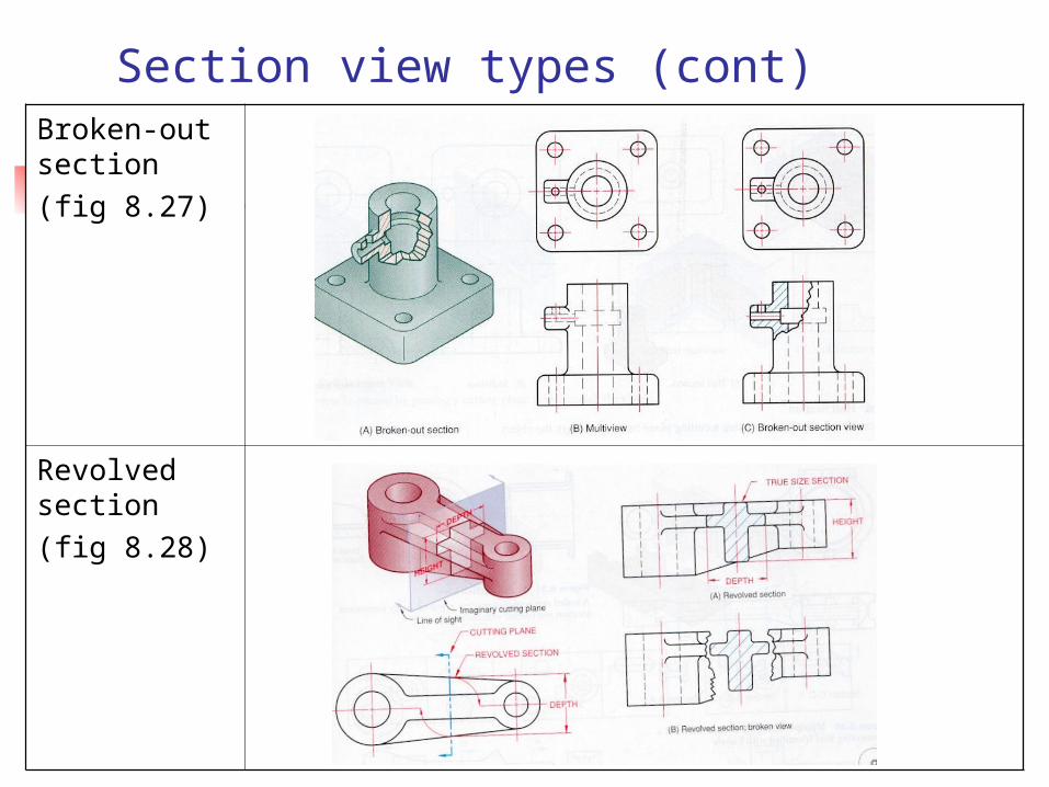
Section view types (cont)Broken-out section(fig 8.27)
Revolved section(fig 8.28)

Section view types (cont)Removed section (fig 8.29)
Offset section (fig 8.33)
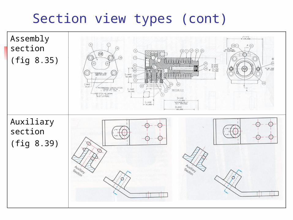
Section view types (cont)Assembly section (fig 8.35)
Auxiliary section (fig 8.39)
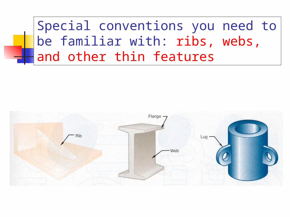
Special conventions you need to be familiar with: ribs, webs, and other thin features
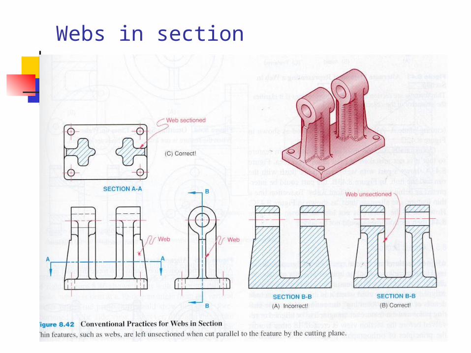
Webs in section
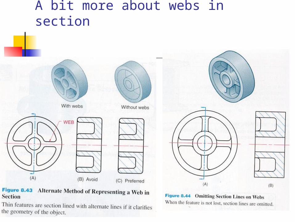
A bit more about webs in section
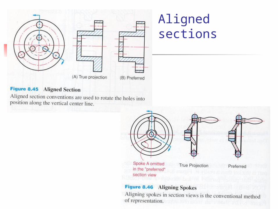
Aligned sections

Conventional breaks: Conventional breaks are used for revolved section views or for shortening the view of an elongated part.
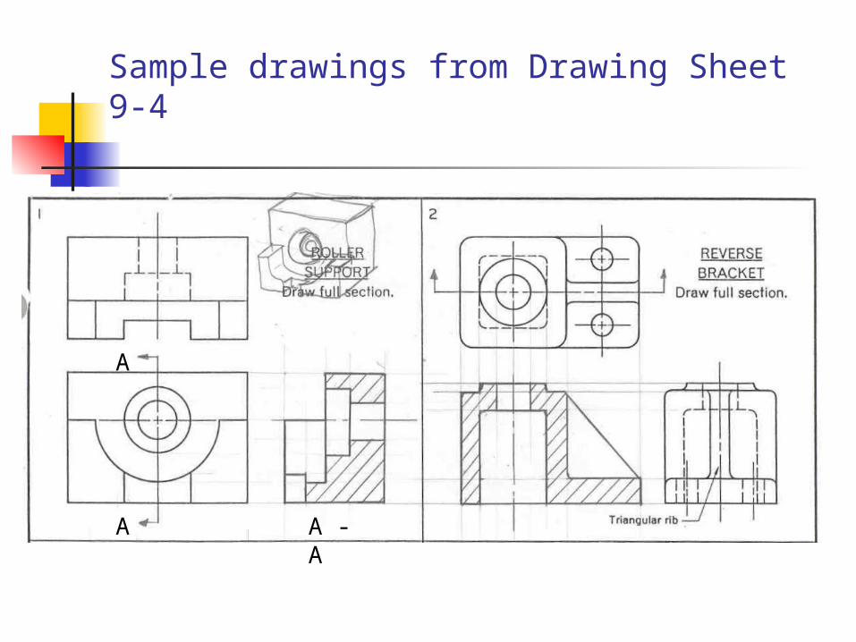
Sample drawings from Drawing Sheet 9-4
A
A A - A
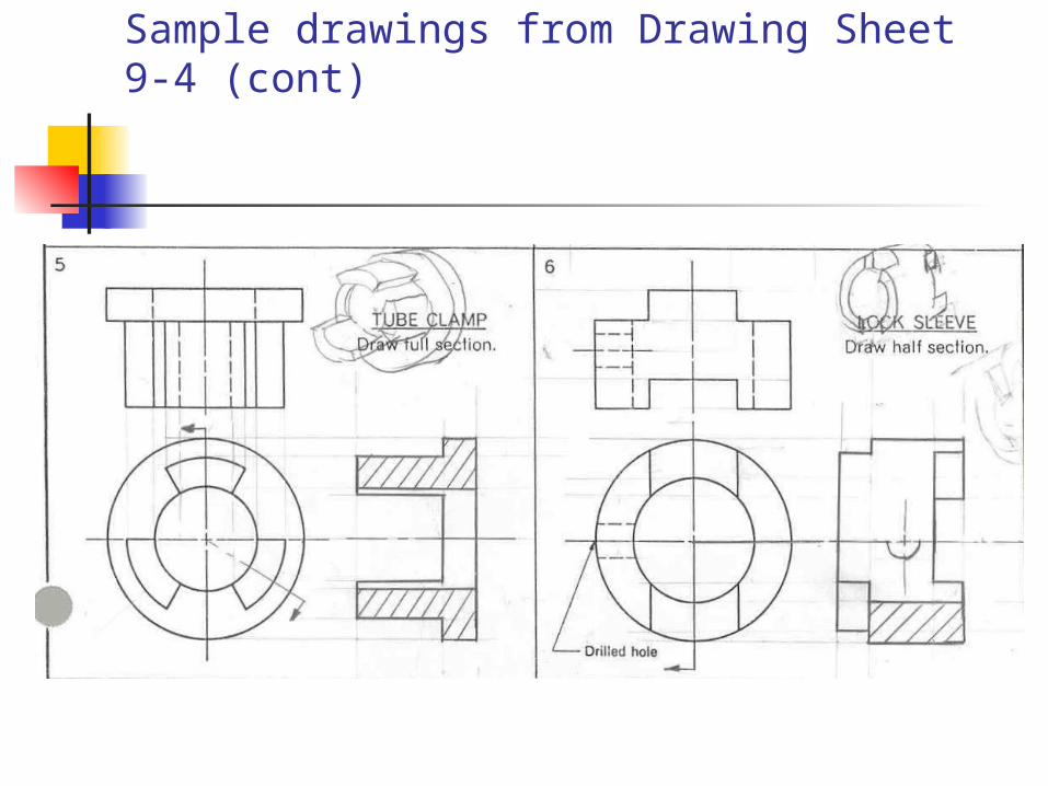
Sample drawings from Drawing Sheet 9-4 (cont)