ch06 mech prop summer2016-sent(1)
TRANSCRIPT
ME3101-Materials Sc. and Engr.
Dr. Atiqullah. Compiled from: Callister and
others 1
ME3101: Materials Sc. & Engr.
Ch 6: Mech. Properties
How many of these terms do we know?
• Anelasticity - viscoelasticity, polymers
• Elastic recovery
• Engineering Stress/strain – materials testing
• True stress/strain – mfg.
• Poisson’s Ratio – mfg.
• Proportional limit – up to which ..
• Toughness – bumper design for absorbing ? energy
• Resilience (p-168) – spring design- energy absorbing but with no
permanent ..?...
Dr. Mir AtiqullahIncludes materials adopted from Callister text
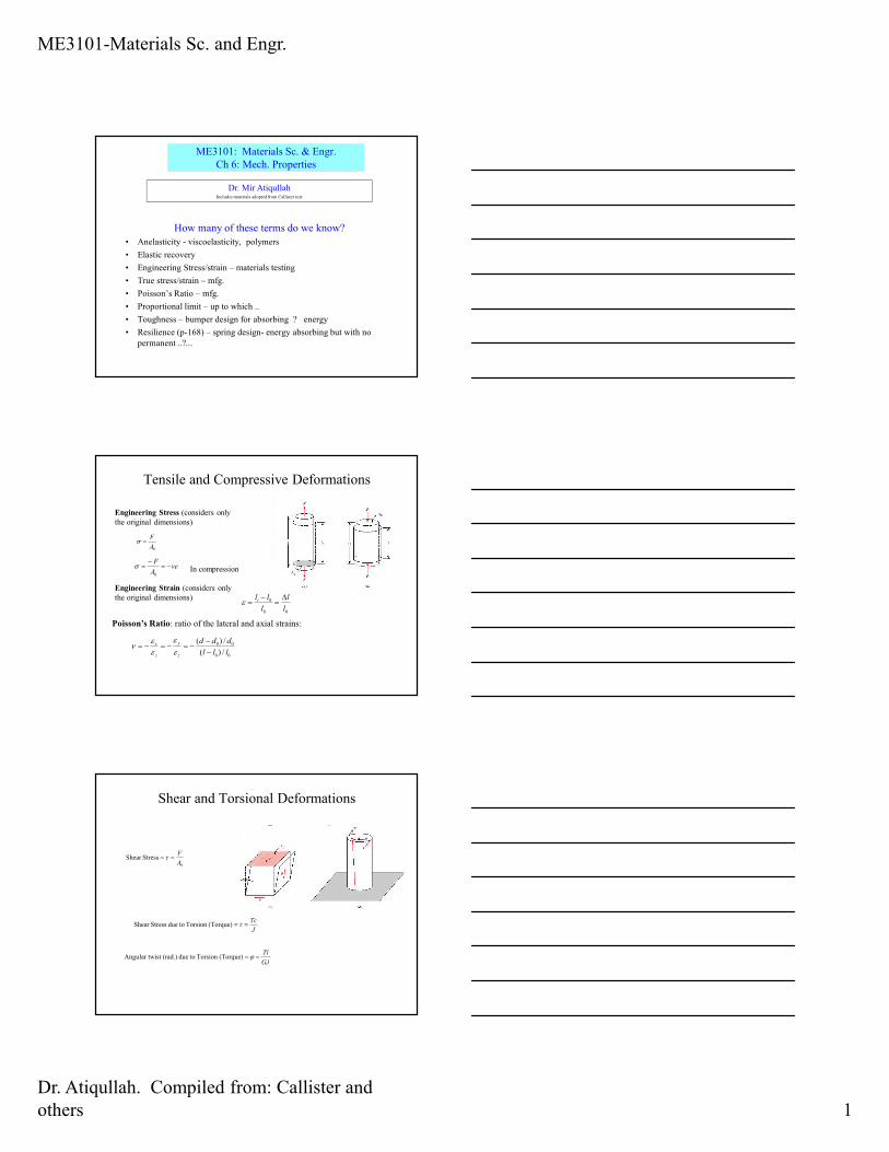
Tensile and Compressive Deformations
0A
F=σ
Engineering Stress (considers only
the original dimensions)
Engineering Strain (considers only
the original dimensions)
00
0
l
l
l
lli ∆=
−=ε
veA
F−=
−=
0
σ In compression
Poisson’s Ratio: ratio of the lateral and axial strains:
00
00
/)(
/)(
lll
ddd
z
y
z
x
−−
−=−=−=εε
εε
ν
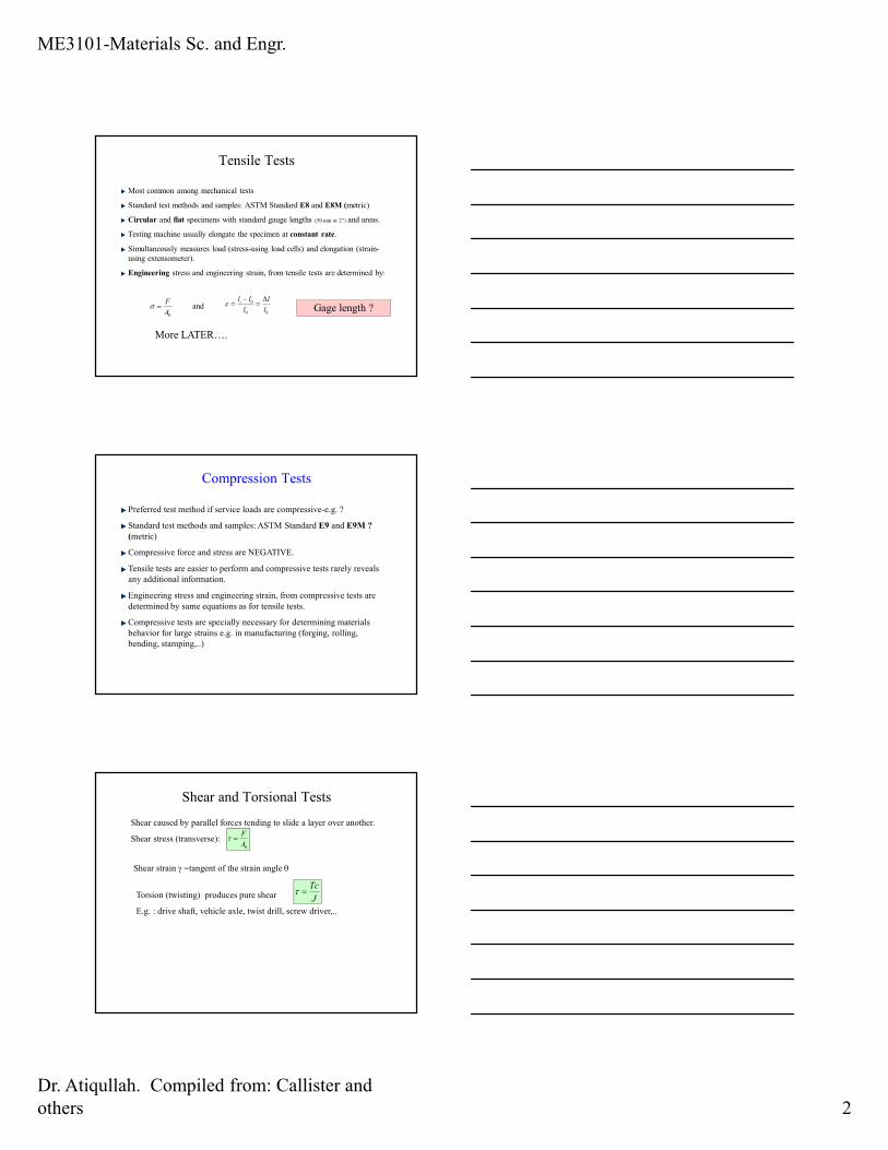
Shear and Torsional Deformations
0
StressShear A
F== τ
J
Tc== τ(Torque) Torsion todue StressShear
GJ
Tl== ϕ(Torque)Torsion todue (rad.)ist Angular tw
ME3101-Materials Sc. and Engr.
Dr. Atiqullah. Compiled from: Callister and
others 2
Tensile Tests
Most common among mechanical tests
Standard test methods and samples: ASTM Standard E8 and E8M (metric)
Circular and flat specimens with standard gauge lengths (50 mm or 2”) and areas.
Testing machine usually elongate the specimen at constant rate.
Simultaneously measures load (stress-using load cells) and elongation (strain-
using extensometer).
Engineering stress and engineering strain, from tensile tests are determined by:
0A
F=σ and
00
0
l
l
l
lli ∆=
−=ε
More LATER….
Gage length ?
Compression Tests
Preferred test method if service loads are compressive-e.g. ?
Standard test methods and samples: ASTM Standard E9 and E9M ?
(metric)
Compressive force and stress are NEGATIVE.
Tensile tests are easier to perform and compressive tests rarely reveals
any additional information.
Engineering stress and engineering strain, from compressive tests are
determined by same equations as for tensile tests.
Compressive tests are specially necessary for determining materials
behavior for large strains e.g. in manufacturing (forging, rolling,
bending, stamping,..)
Shear and Torsional Tests
0A
F=τ
Shear caused by parallel forces tending to slide a layer over another.
Shear stress (transverse):
Shear strain γ =tangent of the strain angle θ
Torsion (twisting) produces pure shear
E.g. : drive shaft, vehicle axle, twist drill, screw driver,..
J
Tc=τ
ME3101-Materials Sc. and Engr.
Dr. Atiqullah. Compiled from: Callister and
others 3
Geometric Considerations of the Stress State
State of Stress is also a function of the
orientation of the plane along which the
stresses are considered. For a plane at an
angle θ: Resolved stresses are-
+⋅=⋅=
2
2cos1cos2' θ
σθσσ
⋅=⋅=2
2sincossin' θ
σθθστ
o45 is max' θτ when=
F
δ
bonds stretch
return to initial
2
1. Initial 2. Small load 3. Unload
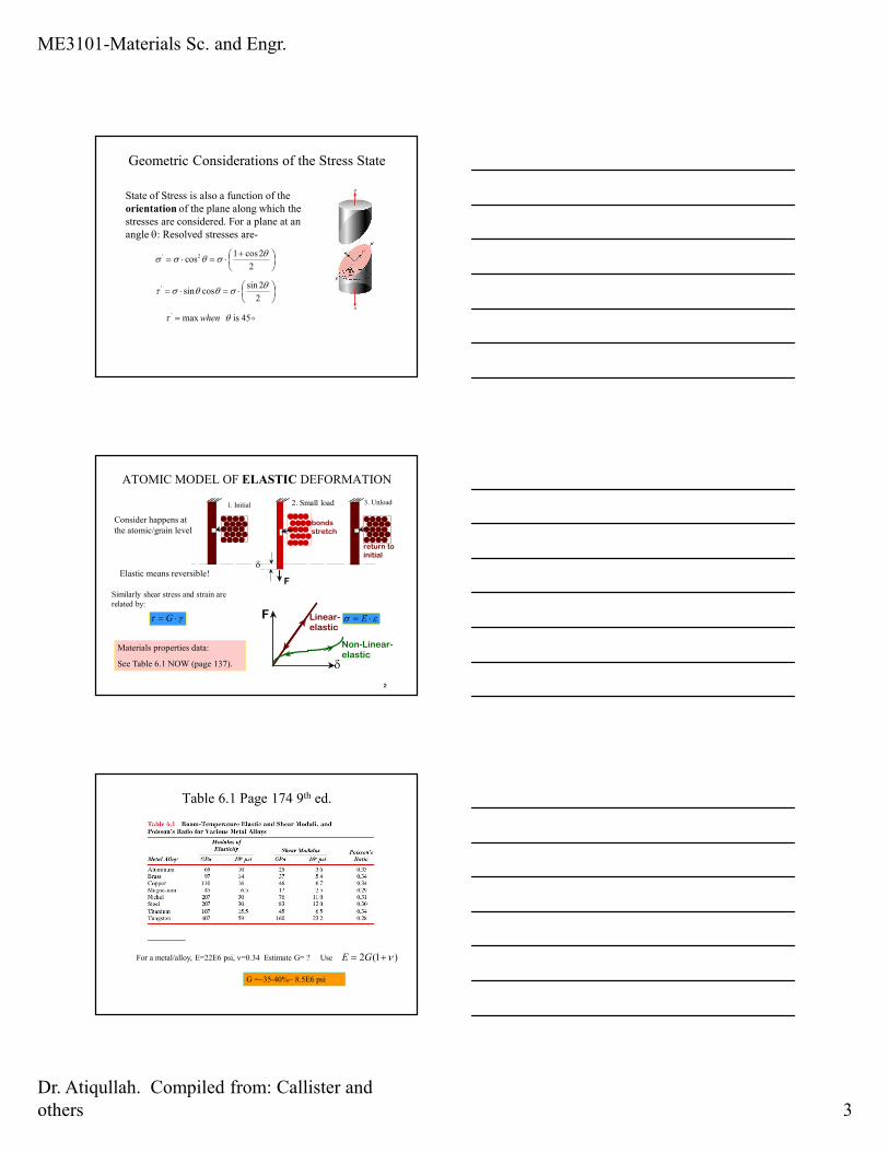
Elastic means reversible!
F
δ
Linear- elastic
Non-Linear-elastic
ATOMIC MODEL OF ELASTIC DEFORMATION
εσ ⋅= E εσ ⋅= E
Consider happens at
the atomic/grain level
Materials properties data:
See Table 6.1 NOW (page 137).
Similarly shear stress and strain are
related by:
γτ ⋅= G γτ ⋅= G
Table 6.1 Page 174 9th ed.
G =~35-40%~ 8.5E6 psi
For a metal/alloy, E=22E6 psi, ν=0.34 Estimate G= ? Use )1(2 ν+= GE
ME3101-Materials Sc. and Engr.
Dr. Atiqullah. Compiled from: Callister and
others 4
3
1. Initial 2. Small load 3. Unload
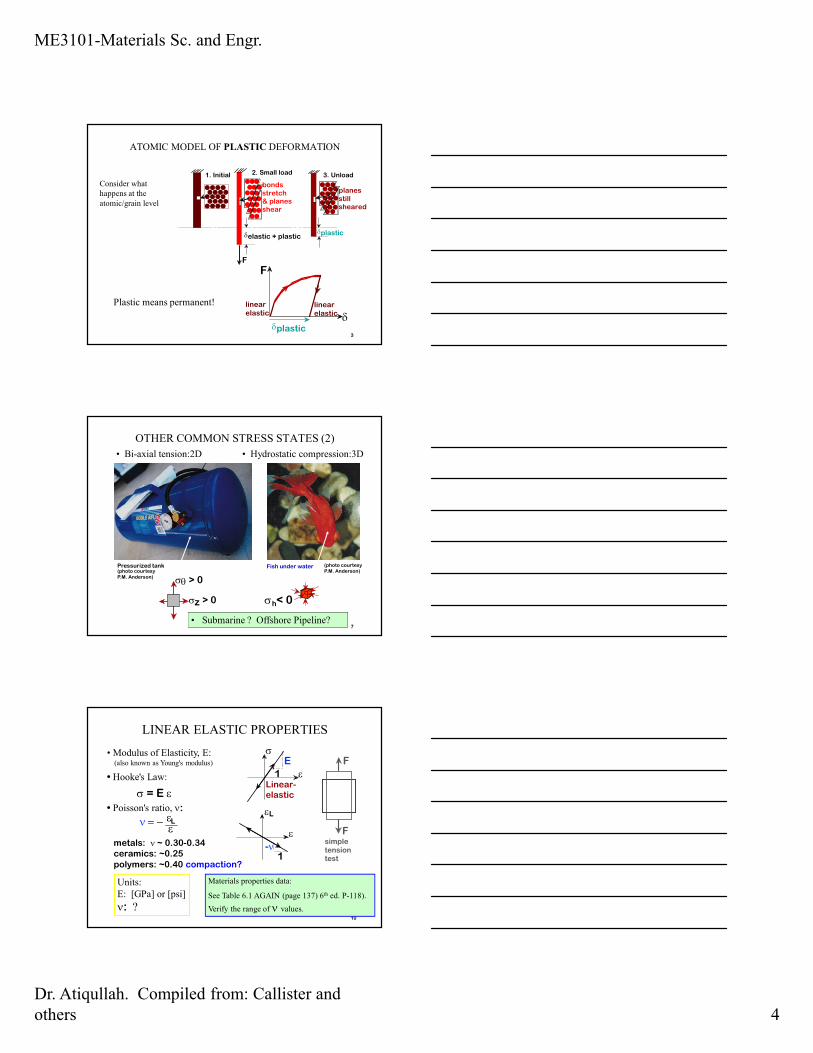
Plastic means permanent!
F
δlinear elastic
linear elastic
δplastic
planes still sheared
F
δelastic + plastic
bonds stretch & planes shear
δplastic
ATOMIC MODEL OF PLASTIC DEFORMATION
Consider what
happens at the
atomic/grain level
7
• Bi-axial tension:2D • Hydrostatic compression:3D
Fish under waterPressurized tank
σz > 0
σθ > 0
σ < 0h
(photo courtesyP.M. Anderson)
(photo courtesyP.M. Anderson)
OTHER COMMON STRESS STATES (2)
• Submarine ? Offshore Pipeline?
• Modulus of Elasticity, E:(also known as Young's modulus)
10
• Hooke's Law:
σ = E ε• Poisson's ratio, ν:
metals: ν ~ 0.30-0.34ceramics: ~0.25polymers: ~0.40 compaction?
εν = − Lε
εL
ε
1-ν
F
Fsimple tension test
σ
Linear- elastic
1
E
ε
Units:
E: [GPa] or [psi]
ν: ?
LINEAR ELASTIC PROPERTIES
Materials properties data:
See Table 6.1 AGAIN (page 137) 6th ed. P-118).
Verify the range of ν values.
ME3101-Materials Sc. and Engr.
Dr. Atiqullah. Compiled from: Callister and
others 5
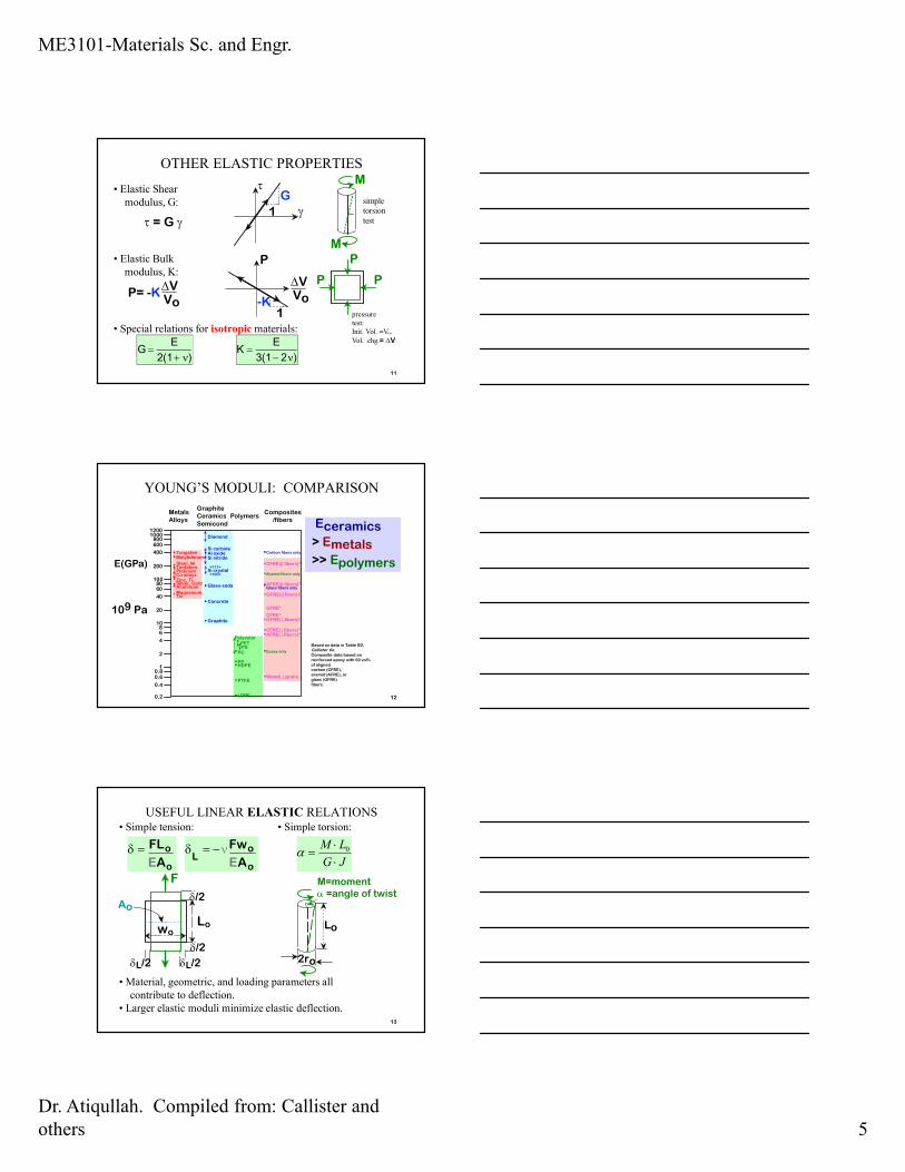
• Elastic Shear
modulus, G:
11
τ
1
Gγ
τ = G γ
• Elastic Bulk
modulus, K:
P= -K∆VVo
P
∆V
1-K
Vo
• Special relations for isotropic materials:
P
P P
M
M
G =
E
2(1+ ν) K =
E
3(1− 2ν)
simple
torsion
test
pressure
test:
Init. Vol. =Vo.
Vol. chg.= ∆V
OTHER ELASTIC PROPERTIES
120.2
8
0.6
1
Magnesium,
Aluminum
Platinum
Silver, Gold
Tantalum
Zinc, Ti
Steel, Ni
Molybdenum
Graphite
Si crystal
Glass-soda
Concrete
Si nitrideAl oxide
PC
Wood( grain)
AFRE( fibers)*
CFRE*
GFRE*
Glass fibers only
Carbon fibers only
Aramid fibers only
Epoxy only
0.4
0.8
2
4
6
10
20
40
6080
100
200
600800
10001200
400
Tin
Cu alloys
Tungsten
<100>
<111>
Si carbide
Diamond
PTFE
HDPE
LDPE
PP
Polyester
PSPET
CFRE( fibers)*
GFRE( fibers)*
GFRE(|| fibers)*
AFRE(|| fibers)*
CFRE(|| fibers)*
MetalsAlloys
GraphiteCeramics
Semicond
PolymersComposites
/fibers
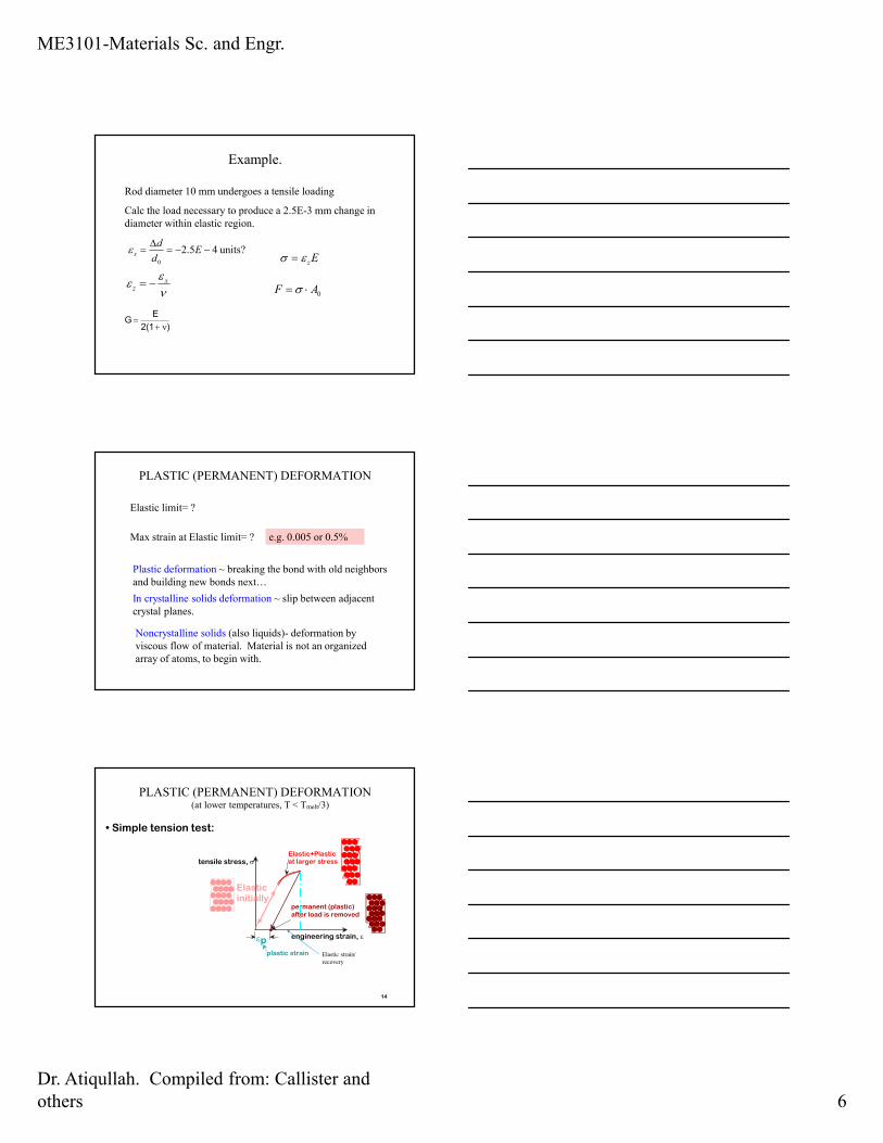
E(GPa)
Eceramics
> Emetals
>> Epolymers
109 Pa
Based on data in Table B2,Callister 6e.Composite data based onreinforced epoxy with 60 vol%of alignedcarbon (CFRE),aramid (AFRE), orglass (GFRE)fibers.
YOUNG’S MODULI: COMPARISON
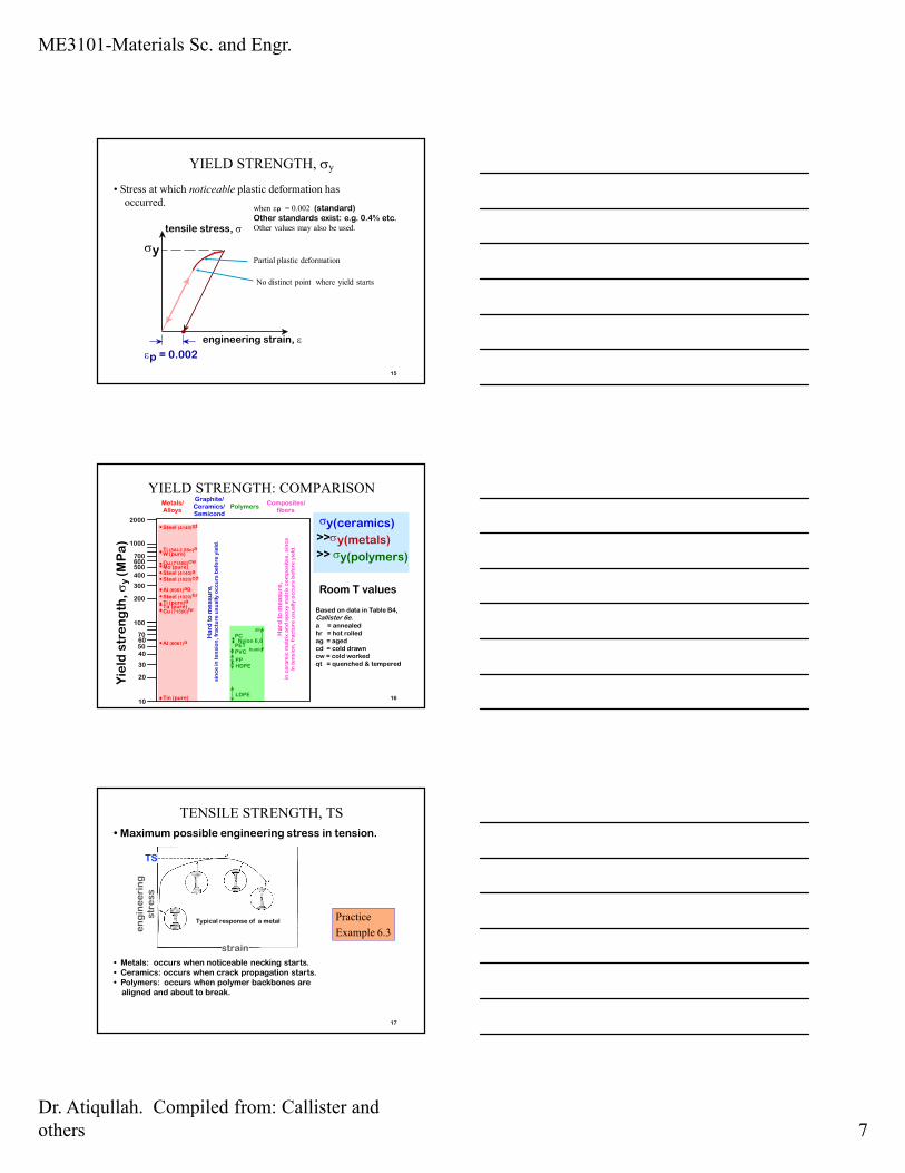
• Simple tension:
13
δ = FLo
EAo
δL
= −νFwo
EAo
δ/2
δ/2
δL/2δL/2
Lowo
F
Ao
• Simple torsion:
M=moment α =angle of twist
2ro
Lo
• Material, geometric, and loading parameters all
contribute to deflection.
• Larger elastic moduli minimize elastic deflection.
USEFUL LINEAR ELASTIC RELATIONS
JG
LM
⋅⋅
= 0α
ME3101-Materials Sc. and Engr.
Dr. Atiqullah. Compiled from: Callister and
others 6
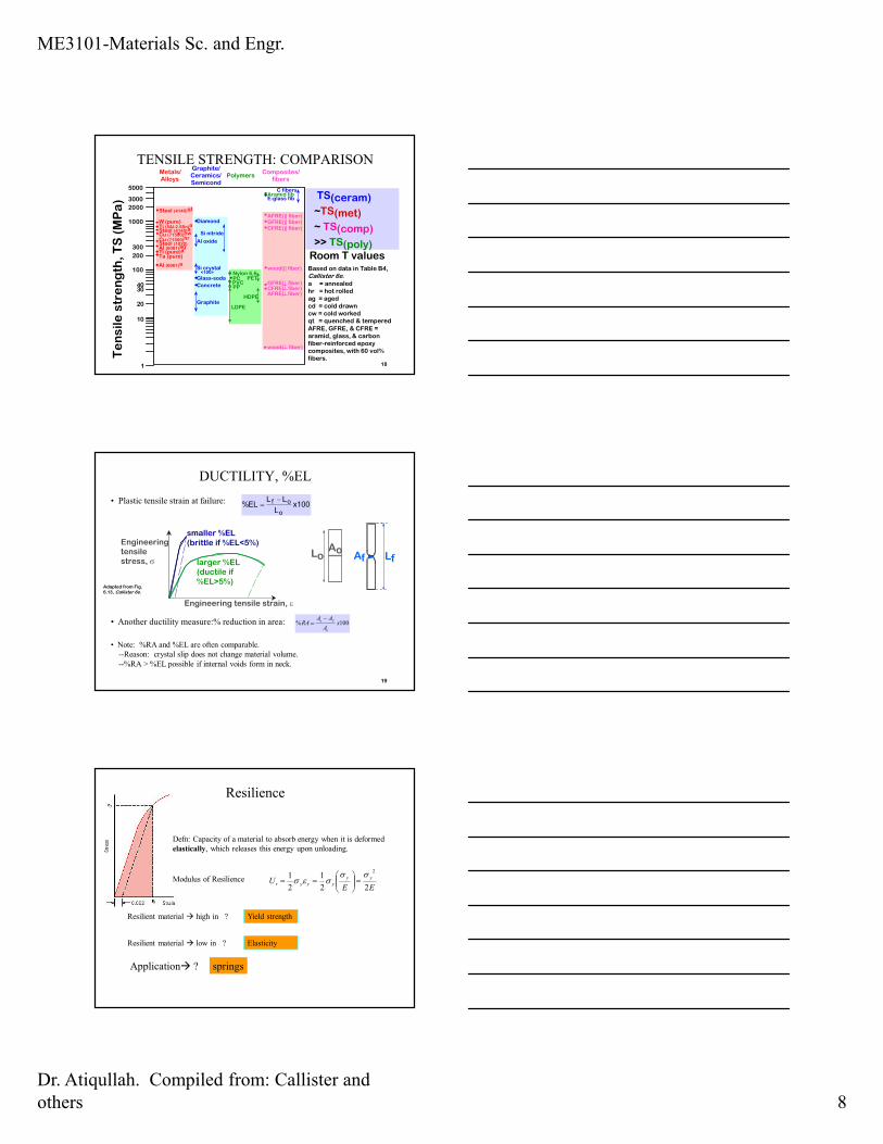
Example.
Rod diameter 10 mm undergoes a tensile loading
Calc the load necessary to produce a 2.5E-3 mm change in
diameter within elastic region.
units? 45.20
−−=∆
= Ed
dxε
νε
ε xz −=
G =
E
2(1+ ν)
Ezεσ =
0AF ⋅= σ
PLASTIC (PERMANENT) DEFORMATION
Elastic limit= ?
Max strain at Elastic limit= ? e.g. 0.005 or 0.5%
Plastic deformation ~ breaking the bond with old neighbors
and building new bonds next…
In crystalline solids deformation ~ slip between adjacent
crystal planes.
Noncrystalline solids (also liquids)- deformation by
viscous flow of material. Material is not an organized
array of atoms, to begin with.
14
• Simple tension test:
(at lower temperatures, T < Tmelt/3)
PLASTIC (PERMANENT) DEFORMATION
tensile stress, σ
engineering strain, ε
Elastic initially
Elastic+Plastic at larger stress
permanent (plastic) after load is removed
εp
plastic strain Elastic strain/
recovery
ME3101-Materials Sc. and Engr.
Dr. Atiqullah. Compiled from: Callister and
others 7
15
• Stress at which noticeable plastic deformation has
occurred.when εp = 0.002 (standard)Other standards exist: e.g. 0.4% etc.Other values may also be used.tensile stress, σ
engineering strain, ε
σy
εp = 0.002
YIELD STRENGTH, σy
Partial plastic deformation
No distinct point where yield starts
16
Graphite/ Ceramics/ Semicond
Metals/ Alloys
Composites/ fibers
Polymers
Yie
ld s
tre
ng
th,
σy
(M
Pa
)
PVC
Ha
rd t
o m
ea
su
re,
s
inc
e i
n t
en
sio
n,
fra
ctu
re u
su
all
y o
cc
urs
be
fore
yie
ld.
Nylon 6,6
LDPE
70
20
40
6050
100
10
30
200
300
400
500600700
1000
2000
Tin (pure)
Al (6061)a
Al (6061)ag
Cu (71500)hrTa (pure)Ti (pure)aSteel (1020)hr
Steel (1020)cdSteel (4140)a
Steel (4140)qt
Ti (5Al-2.5Sn)aW (pure)
Mo (pure)Cu (71500)cw
Ha
rd t
o m
ea
su
re,
in c
era
mic
ma
trix
an
d e
po
xy
ma
trix
co
mp
os
ite
s,
sin
ce
in
te
ns
ion
, fr
ac
ture
us
ua
lly
oc
cu
rs b
efo
re y
ield
.
HDPEPP
humid
dry
PC
PET
¨
Room T values
σy(ceramics)
>>σy(metals)
>> σy(polymers)
Based on data in Table B4,Callister 6e.
a = annealedhr = hot rolledag = agedcd = cold drawncw = cold workedqt = quenched & tempered
YIELD STRENGTH: COMPARISON
17
• Maximum possible engineering stress in tension.
• Metals: occurs when noticeable necking starts.• Ceramics: occurs when crack propagation starts.• Polymers: occurs when polymer backbones are
aligned and about to break.
TENSILE STRENGTH, TS
strain
en
gin
ee
rin
g
str
es
s
TS
Typical response of a metal Practice
Example 6.3
ME3101-Materials Sc. and Engr.
Dr. Atiqullah. Compiled from: Callister and
others 8
18
Room T valuesSi crystal
<100>
Graphite/ Ceramics/ Semicond
Metals/ Alloys
Composites/ fibers
Polymers
Te
ns
ile
str
en
gth
, T
S (
MP
a)
PVC
Nylon 6,6
10
100
200
300
1000
Al (6061)a
Al (6061)ag
Cu (71500)hr
Ta (pure)Ti (pure)a
Steel (1020)
Steel (4140)a
Steel (4140)qt
Ti (5Al-2.5Sn)aW (pure)
Cu (71500)cw
LDPE
PP
PC PET
20
3040
2000
3000
5000
Graphite
Al oxide
Concrete
Diamond
Glass-soda
Si nitride
HDPE
wood( fiber)
wood(|| fiber)
1
GFRE(|| fiber)
GFRE( fiber)
CFRE(|| fiber)
CFRE( fiber)
AFRE(|| fiber)
AFRE( fiber)
E-glass fib
C fibersAramid fib TS(ceram)
~TS(met)
~ TS(comp)
>> TS(poly)
Based on data in Table B4,Callister 6e.
a = annealedhr = hot rolledag = agedcd = cold drawncw = cold workedqt = quenched & tempered
AFRE, GFRE, & CFRE =aramid, glass, & carbonfiber-reinforced epoxycomposites, with 60 vol%fibers.
TENSILE STRENGTH: COMPARISON
• Plastic tensile strain at failure:
19
Engineering tensile strain, ε
Engineering tensile stress, σ
smaller %EL (brittle if %EL<5%)
larger %EL (ductile if %EL>5%)
• Another ductility measure:% reduction in area: 100% xA
AARA
o
fo −=
• Note: %RA and %EL are often comparable.
--Reason: crystal slip does not change material volume.
--%RA > %EL possible if internal voids form in neck.
Lo LfAo
Af
%EL =
L f − Lo
Lo
x100
Adapted from Fig. 6.13, Callister 6e.
DUCTILITY, %EL
Resilience
Defn: Capacity of a material to absorb energy when it is deformed
elastically, which releases this energy upon unloading.
Modulus of ResilienceEE
Uyy
yyyr22
1
2
12σσ
σεσ =
==
Resilient material � high in ?
Resilient material � low in ?
Yield strength
Elasticity
Application� ? springssprings
ME3101-Materials Sc. and Engr.
Dr. Atiqullah. Compiled from: Callister and
others 9
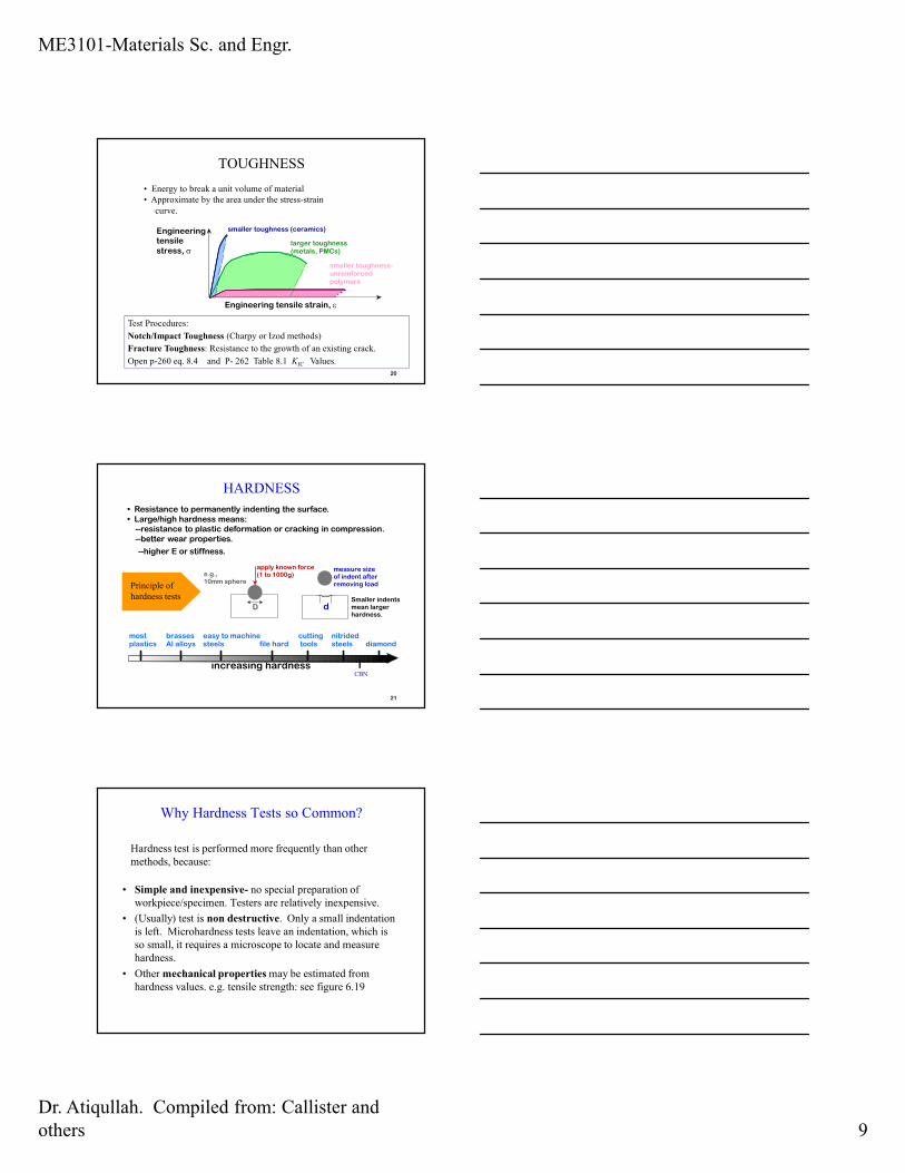
• Energy to break a unit volume of material
• Approximate by the area under the stress-strain
curve.
20
smaller toughness- unreinforced polymers
Engineering tensile strain, ε
Engineering tensile stress, σ
smaller toughness (ceramics)
larger toughness (metals, PMCs)
TOUGHNESS
Test Procedures:
Notch/Impact Toughness (Charpy or Izod methods)
Fracture Toughness: Resistance to the growth of an existing crack.
Open p-260 eq. 8.4 and P- 262 Table 8.1 KIC Values.
• Resistance to permanently indenting the surface.• Large/high hardness means:
--resistance to plastic deformation or cracking in compression.--better wear properties.
--higher E or stiffness.
21
e.g., 10mm sphere
apply known force (1 to 1000g)
measure size of indent after removing load
dDSmaller indents mean larger hardness.
increasing hardness
most plastics
brasses Al alloys
easy to machine steels file hard
cutting tools
nitrided steels diamond
HARDNESS
Principle of
hardness tests
CBN
Why Hardness Tests so Common?
• Simple and inexpensive- no special preparation of
workpiece/specimen. Testers are relatively inexpensive.
• (Usually) test is non destructive. Only a small indentation
is left. Microhardness tests leave an indentation, which is
so small, it requires a microscope to locate and measure
hardness.
• Other mechanical properties may be estimated from
hardness values. e.g. tensile strength: see figure 6.19
Hardness test is performed more frequently than other
methods, because:
ME3101-Materials Sc. and Engr.
Dr. Atiqullah. Compiled from: Callister and
others 10
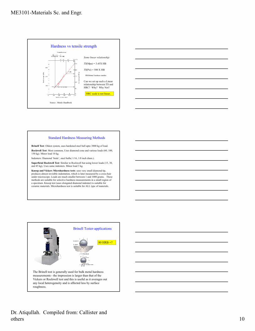
Hardness vs tensile strength
Source : Metals Handbook
Some linear relationship:
TS(Mpa) = 3.45X HB
TS(Psi) = 500 X HB
HB-Brinnel hardness number.
Can we set up such a Linear
relationship between TS and
HRC? Why? Why Not?
HRC scale is not linear..
Standard Hardness Measuring Methods
Brinell Test: Oldest system, uses hardened steel ball upto 3000 kg of load.
Rockwell Test: Most common, Uses diamond cone and various loads (60, 100,
150 kg). Minor load 10 kg.
Indenters: Diamond ‘brale’, steel balls( 1/16, 1/8 inch diam.).
Superficial Rockwell Test: Similar to Rockwell but using lower loads (15, 30,
and 45 kg), Uses same indenters. Minor load 3 kg.
Knoop and Vickers Microhardness tests: uses very small diamond tip,
produces almost invisible indentation, which is later measured by a cross-hair
under microscope. Loads are much smaller between 1 and 1000 grams. These
methods are suitable for selective hardness measurements in a small region of
a specimen. Knoop test (uses elongated diamond indenter) is suitable for
ceramic materials. Microhardness test is suitable for ALL type of materials.
Brinell Tester-applications
The Brinell test is generally used for bulk metal hardness
measurements - the impression is larger than that of the
Vickers or Rockwell test and this is useful as it averages out
any local heterogeneity and is affected less by surface
roughness.
80 HRB =?
ME3101-Materials Sc. and Engr.
Dr. Atiqullah. Compiled from: Callister and
others 11
Brinell Hardness Test-Limitations
However, because of the large ball diameter the test cannot be
used to determine the hardness variations in a welded joint for
which the Vickers test is preferred.
Very hard metals, over 450BHN may also cause the ball to
deform resulting in an inaccurate reading.
To overcome this limitation a tungsten carbide ball is used
instead of the hardened steel ball but there is also a hardness
limit of 600BHN with this indentor.
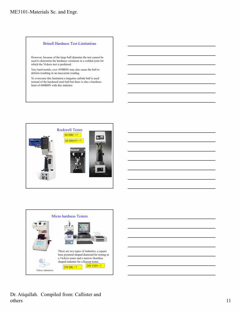
Rockwell Tester
A modern Rockwell
Hardness tester ( Dream)
Specimen
Indenter
80 HRC =?
60 HR45T =?
A Rockwell Hardness
tester
Micro hardness Testers
There are two types of indenters, a square
base pyramid shaped diamond for testing in
a Vickers tester and a narrow rhombus
shaped indenter for a Knoop tester.
Vickers indentation
250 HK =?200 VHN =?
ME3101-Materials Sc. and Engr.
Dr. Atiqullah. Compiled from: Callister and
others 12
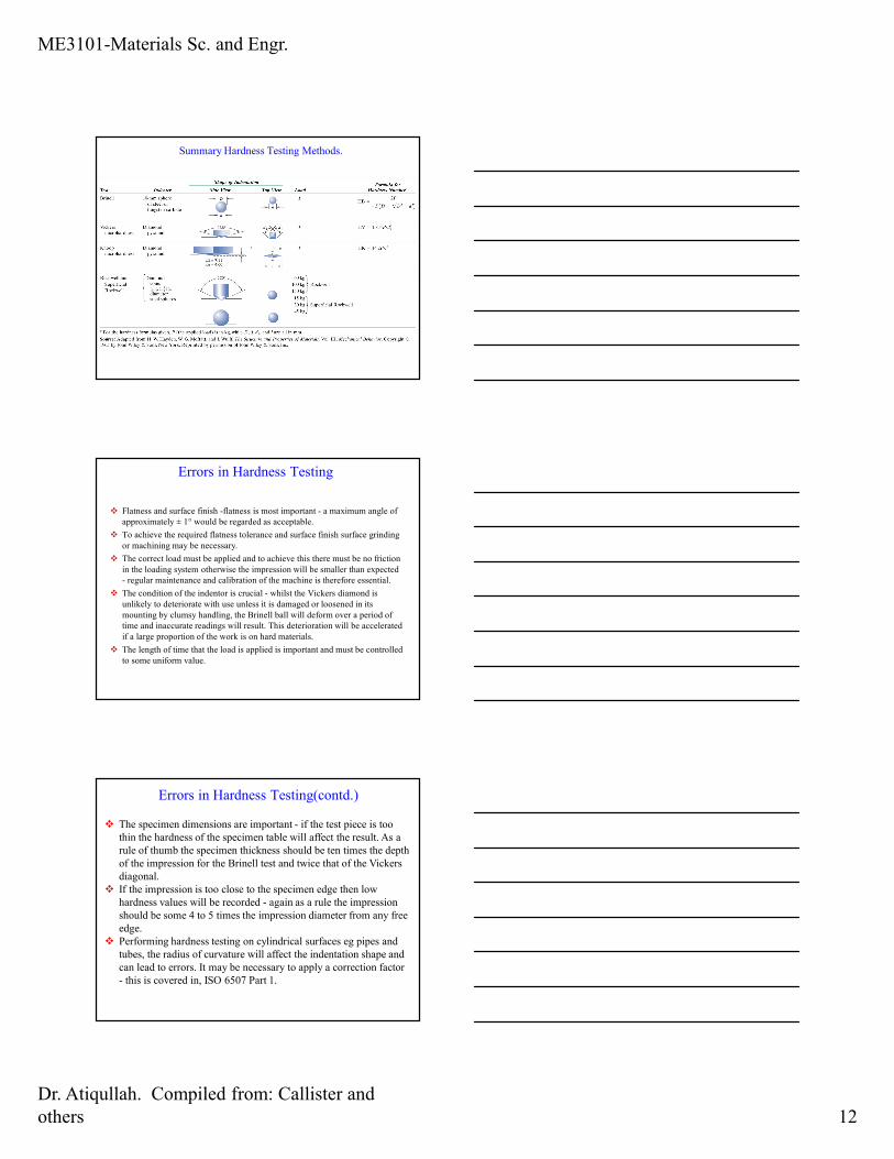
Summary Hardness Testing Methods.
Errors in Hardness Testing
� Flatness and surface finish -flatness is most important - a maximum angle of
approximately ± 1° would be regarded as acceptable.
� To achieve the required flatness tolerance and surface finish surface grinding
or machining may be necessary.
� The correct load must be applied and to achieve this there must be no friction
in the loading system otherwise the impression will be smaller than expected
- regular maintenance and calibration of the machine is therefore essential.
� The condition of the indentor is crucial - whilst the Vickers diamond is
unlikely to deteriorate with use unless it is damaged or loosened in its
mounting by clumsy handling, the Brinell ball will deform over a period of
time and inaccurate readings will result. This deterioration will be accelerated
if a large proportion of the work is on hard materials.
� The length of time that the load is applied is important and must be controlled
to some uniform value.
Errors in Hardness Testing(contd.)
� The specimen dimensions are important - if the test piece is too
thin the hardness of the specimen table will affect the result. As a
rule of thumb the specimen thickness should be ten times the depth
of the impression for the Brinell test and twice that of the Vickers
diagonal.
� If the impression is too close to the specimen edge then low
hardness values will be recorded - again as a rule the impression
should be some 4 to 5 times the impression diameter from any free
edge.
� Performing hardness testing on cylindrical surfaces eg pipes and
tubes, the radius of curvature will affect the indentation shape and
can lead to errors. It may be necessary to apply a correction factor
- this is covered in, ISO 6507 Part 1.
ME3101-Materials Sc. and Engr.
Dr. Atiqullah. Compiled from: Callister and
others 13
Errors in Hardness Testing(contd.)
� The specimen table should be rigidly supported and must be
in good condition - burrs or raised edges beneath the
sample will give low readings.
� Impact loading must be avoided. It is very easy to force the
indentor into the specimen surface when raising the table
into position. This can strain the equipment and damage the
indentor.
� Operator (or student) training is crucial and
� Regular validation or calibration is essential if hardness rest
results are to be accurate and reproducible.
(material compiled from various sources)
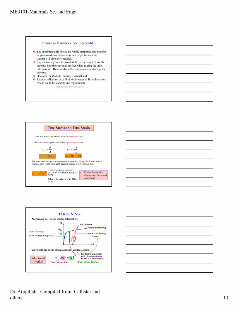
True Stress and True Strain
Defn: True Stress= applied load divided by instantaneous area.
Defn: True Stress= applied load divided by instantaneous area.
0
lnl
lT =ε
i
TA
F=σ
)1( εσσ +=T)1ln( εε +=T
For some metals/alloys, true stress-strain relationship during plastic deformation
meaning after yielding and until necking begins, is approximated by:
n
TT K εσ ⋅=n=strain hardening exponent.
(0.12-0.5) See Table 6.4 page 171
NOW
What is the value of n for 2024-
T3 Al ?
• What is the equation
relating engr. Stress and
engr strain?
• An increase in σy due to plastic deformation.
• Curve fit to the stress-strain response –yield to necking :
σ
ε
large hardening
small hardening
un
loa
d
relo
ad
σy 0
σy 1
σT = C εT( )n
“true” stress (F/A) “true” strain: ln(L/Lo)
hardening exponent: n=0.15 (some steels) to n=0.5 (some copper)
HARDENING
Elastic Recovery:
Return to original shape/size (slope)
New yield point
Who said it
works?
ME3101-Materials Sc. and Engr.
Dr. Atiqullah. Compiled from: Callister and
others 14
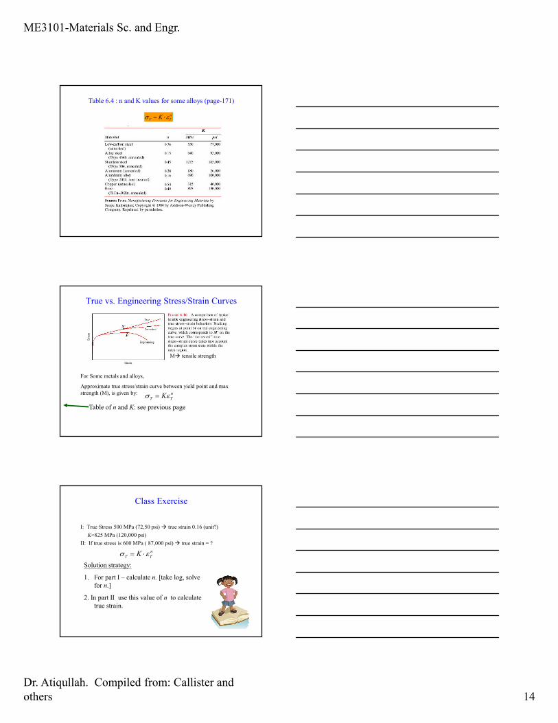
Table 6.4 : n and K values for some alloys (page-171)
n
TT K εσ ⋅=
True vs. Engineering Stress/Strain Curves
M� tensile strength
For Some metals and alloys,
Approximate true stress/strain curve between yield point and max
strength (M), is given by: n
TT Kεσ =
Table of n and K: see previous page
Class Exercise
I: True Stress 500 MPa (72,50 psi) � true strain 0.16 (unit?)
K=825 MPa (120,000 psi)
II: If true stress is 600 MPa ( 87,000 psi) � true strain = ?
n
TT K εσ ⋅=
Solution strategy:
1. For part I – calculate n. [take log, solve
for n.]
2. In part II use this value of n to calculate
true strain.
ME3101-Materials Sc. and Engr.
Dr. Atiqullah. Compiled from: Callister and
others 15
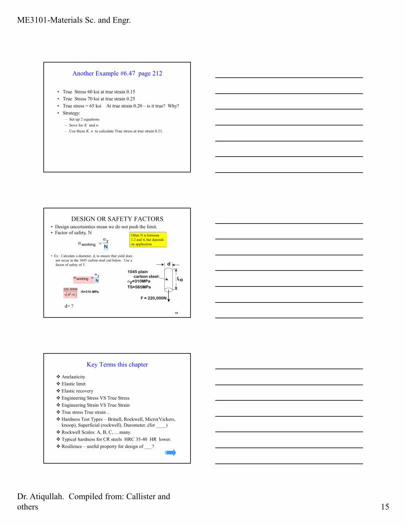
Another Example #6.47 page 212
• True Stress 60 ksi at true strain 0.15
• True Stress 70 ksi at true strain 0.25
• True stress = 65 ksi At true strain 0.20 – is it true? Why?
• Strategy:
– Set up 2 equations
– Sove for K and n.
– Use these K, n to calculate True stress at true strain 0.21.
• Design uncertainties mean we do not push the limit.
• Factor of safety, N
23
σworking =
σy
N
Often N is between
1.2 and 4, but depends
on application
• Ex: Calculate a diameter, d, to ensure that yield does
not occur in the 1045 carbon steel rod below. Use a
factor of safety of 5.
1045 plain carbon steel: σy=310MPa
TS=565MPa
F = 220,000N
d
Lo σworking =
σy
N
220,000N
π d2 /4
/5=310 MPa
DESIGN OR SAFETY FACTORS
d= ?
Key Terms this chapter
� Anelasticity
� Elastic limit
� Elastic recovery
� Engineering Stress VS True Stress
� Engineering Strain VS True Strain
� True stress True strain ..
� Hardness Test Types – Brinell, Rockwell, Micro(Vickers,
knoop), Superficial (rockwell), Durometer..(for ____)
� Rockwell Scales: A, B, C, ....many.
� Typical hardness for CR steels HRC 35-40 HR lower.
� Resilience – useful property for design of ___?