ch 1 general info & maint
DESCRIPTION
MisubushiTRANSCRIPT

HOW TO USE THIS BOOK 1-2 WHERE TOBEGIN l-2 AVOIDINGTROUBLE 1-2 MAINTENANCEORREPAIR? 1-2 AVOIDINGTHEMOSTCOMMONMISTAKES l-2 TOOLS AND EQUIPMENT 1-2 SPECIALTOOLS l-4
YOUR VEHICLE SAFELY 1-4
DON'TS l-6 FASTENERS, MEASUREMENTS AND
CONVERSIONS l-6 BOLTS,NUTSANDOTHERTHREADED
RETAINERS 1-6 TORQUE l-7
TORQUEWRENCHES l-7 TORQUEANGLEMETERS 1-9
STANDARDANDMETRIC MEASUREMENTS l-9 SERIAL NUMBER IDENTIFICATION l-10 VEHICLE IDENTIFICATION NUMBER l-10 ENGINE IDENTIFICATION NUMBER I-10 TRANSAXLEIDENTIFICATION I-10 DRlVEAXLE(AWDGALANTONLY) l-10 TRANSFERCASE(AWDGALANTONLY) l-10 ROUTINE MAINTENANCE AND TUNE-UP l-14 AIRCLEANER(ELEMENT) 1-14
REMOVAL&INSTALLATION 1-14 FUELFILTER 1-15
REMOVAL &INSTALLATION l-15 PCVVALVE l-15
REMOVAL&INSTALLATION l-15 EVAPORATIVECANISTER l-16
SERVICING 1-16 BATTERY 1-16
PRECAUTIONS I-16 GENERALMAINTENANCE 1-16
BEL
BATTERYFLUID 1-16 CABLES I-17 CHARGING I-18 REPLACEMENT 1-18 TS 1-18 INSPECTiON l-18 ADJUSTMENT 1-18 REMOVAL&INSTALLATION 1-18
TIMINGBELTS l-20 INSPECTION l-20
HOSES I-20 INSPECTION l-20 REMOVAL&INSTALLATION
CV-BOOTS 1-21 INSPECTION l-21
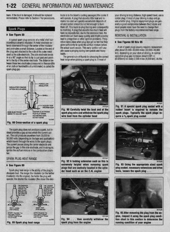
SPARKPLUGS l-22 SPARKPLUGHEATRANGE REMOVAL&INSTALLATION INSPECTION &GAPPING 1.
SPARKPLUG WIRES 1-24 TESTING 1-24 REMOVAL&INSTALLATION
DISTRIBUTORCAPANDROTOR REMOVAL&INSTALLATION INSPECTION 1-25
IGNITIONTIMING 1-25 . GENERALINFORAMTION l-
lNSPECTlON&ADJUSTMENl VALVE LASH l-27
ADJUSTMENT l-27 IDLESPEED 1-28
1-21
l-22 l-22
-23
1-24 l-25 l-25
.25 1-26
AIR CONDITIONING SYSTEM 1-28 SYSTEMSERVlCEiiREPAlR l-28 PREVENTIVEMAINTENANCE 1-28 SYSTEM INSPECTION l-29
WINDSHIELD WIPERS l-29 ELEMENT(REFILL)CARE&
REPLACEMENT l-29 TIRESANDWHEELS l-30
TIRE ROTATION I-30 TIRE DESIGN 1-31 TIRESTORAGE l-31 INFLATION &INSPECTION l-31 CARE OFSPECIALWHEELS l-32
OPERATION INFOREIGNCOUNTRIES l-33 ENGINE l-33
OILLEVELCHECK 1-33 OIL& FILTER CHANGE l-34
MANUALTRANSAXLE l-35 FLUIDRECOMMENDATIONS l-35 LEVELCHECK l-35 DRAIN&REFILL l-36
AUTOMATICTRANSAXLE l-36 FLUIDRECOMMENDATIONS l-36 LEVELCHECK 1-36 DRAIN&REFILL l-36 PAN & FILTERSERVICE 1-36
TRANSFERCASE(AWDGAlANT ONLY) l-38 FLUIDRECOMMENDATIONS l-38 LEVELCHECK l-38 DRAIN&REFILL l-38
REARDRlVEAXLE(AWDGALANTONLY) l-38 FLUIDRECOMMENDATIONS l-38 LEVELCHECK l-38 DRAIN&REFILL l-38
COOLINGSYSTEM l-39 FLUIDRECOMMENDATIONS l-39
iM-41
FLUIDS AND LUBRICANTS 1-33 FLUID DISPOSAL 1-33 FlJELANDENGlNEOILRECOMMENDATlONS
ENGINE OIL l-33 FUEL l-33

.
1-2 GENERALINFORMATIONAND MAINTENANCE
Chitton’s Total Car Care manual for the 199M10 Mitsubishi Mirage, Galant and Diamante is intended to help you learn more about the inner workings of your vehicle while saving you money on its upkeep and operation.
The beginning of the book will likely be referred to the most, since that is where you will find information for maintenance and tune-up. The other sections deal with the more complex systems of your vehicle. Oper- ating systems from engine through brakes are cov- ered to the extent that the average do-it-yourselfer be- comes mechanically involved. This book will not explain such things as rebuilding a differential for the simple reason that the expertise required and the in- vestment in special tools make this task uneconomi- cal. It will, however, give you detailed instructions to help you change your own brake pads and shoes, re- place spark plugs, and perform many more jobs that can save you money, give you personal satisfaction and help you avoid expensive problems.
A secondary purpose of this book is a reference for owners who want to understand their vehicle and/or their mechanics better. In this case, no tools at all are required.
Before removing any bolts, read through the entire procedure. This will give you the overall view of what tools and supplies will be required. There is nothing more frustrating than having to walk to the bus stop on Monday morning because you were short one bolt on Sunday afternoon. So read ahead and plan ahead. Each operation should be approached logically and all procedures thoroughly understood before attempt- ing any work.
All sections contain adjustments, maintenance, re- moval and installation procedures, and in some cases, repair or overhaul procedures. When repair is not con- sidered practical, we tell you how to remove the part and then how to install the new or rebuilt replacement. In this way, you at least save labor costs. “Backyard” repair of some components is just not practical.
Many procedures in this book require you to “label and disconnect. . ” a group of lines, hoses or wires. Don’t be lulled into thinking you can remember where everything goes-you won’t. If you hook up vacuum or fuel lines incorrectly, the vehicle may run poorly, if at all. If you hook up electrical wiring incorrectly, you may instantly learn a very expensive lesson.
You don’t need to know the official or engineering name for each hose or line. A piece of masking tape on the hose and a piece on its fitting will allow you to assign your own label such as the letter A or a short
name. As long as you remember your own code, the lines can be reconnected by matching similar letters or names. Do remember that tape will dissolve in gasolrne or other fluids; if a component is to be washed or cleaned, use another method of identifica- tion. A permanent felt-tipped marker or a metal scribe can be very handy for marking metal parts. Remove any tape or paper labels after assembly.
It’s necessary to mention the difference between maintenance and repair Maintenance includes rou- tine inspections, adjustments, and replacement of parts which show signs of normal wear Maintenance compensates for wear or deterioration. Repair implies that something has broken or is not working. A need for repair is often caused by lack of maintenance. Ex- ample, draining and refilling the automatic transaxle fluid is maintenance recommended by the manufac- turer at specific mileage intervals. Failure to do this can shorten the life of the transmission/transaxle, re- quiring very expensive repairs. While no maintenance program can prevent items from breaking or wearing out, a general rule can be stated: MAINTENANCE IS CHEAPER THAN REPAIR.
Two basic mechanrc’s rules should be mentioned here. First, whenever the left side of the vehicle or en- gine is referred to, it is meant to specify the drivers side. Conversely, the right side of the vehicle means the passengers side. Second, screws and bolts are removed by turning counterclockwise, and tightened by turning clockwrse unless specifically noted.
Safety is always the most important rule. Con- stantly be aware of the dangers involved in working on an automobile and take the proper precautions. See the informatron in this section regarding SER- VICING YOUR VEHICLE SAFELY and the SAFETY NOTICE on the acknowledgment page.
Pay attention to the instructions provided. There are 3 common mistakes in mechanical work:
1. Incorrect order of assembly, disassembly or adjustment. When taking something apart or putting it together, performing steps in the wrong order usu- ally just costs you extra time; however, it CAN break something. Read the entire procedure before begin- ning disassembly. Perform everything in the order in which the instructions say you should, even if you can’t immedrately see a reason for it. When you’re taking apart something that is very intricate, you might want to draw a picture of how it looks when as- sembled at one point in order to make sure you get
everything back in its proper position. We will supply exploded views whenever possible. When making adjustments, perform them in the proper order. One adjustment possibly will affect another.
2. Overtorquing (or undertorquing). While it is more common for overtorquing to cause damage, undertorquing may allow a fastener to vibrate loose causing serious damage. Especially when dealing with aluminum parts, pay attention to torque specifi- cations and utilize a torque wrench in assembly. If a torque figure is not available, remember that if you are using the right tool to perform the job, you will probably not have to strain yourself to get a fastener tight enough. The pitch of most threads is so slight that the tension you put on the wrench will be multi- plied many times in actual force on what you are tightening. A good example of how critical torque is can be seen in the case of spark plug installation, es- pecially where you are putting the plug into an alu- minum cylinder head. Too little torque can fail to crush the gasket, causing leakage of combustion gases and consequent overheating of the plug and engine parts. Too much torque can damage the threads or distort the plug, changing the spark gap.
There are many commercial products available for ensuring that fasteners won’t come loose, even if they are not torqued just right (a very common brand is Loctite? If you’re worried about getting something together tight enough to hold, but loose enough to avoid mechanical damage during assembly, one of these products might offer substantial insurance. Be- fore choosing a threadlocking compound, read the label on the package and make sure the product is compatible with the materials, fluids, etc. involved.
3. Crossthreading. This occurs when a part such as a bolt is screwed into a nut or casting at the wrong angle and forced. Crossthreading is more likely to occur if access is difficult. It helps to clean and lubri- cate fasteners, then to start threading the bolt, spark plug, etc. with your fingers If you encounter resis- tance, unscrew the part and start over again at a dif- ferent angle until it can be inserted and turned several times without much effort. Keep in mind that many parts, especially spark plugs, have tapered threads, so that gentle turning will automatically bring the part you’re threading to the proper angle. Don’t put a wrench on the part until its been tightened a couple of turns by hand. If you suddenly encounter resis- tance, and the part has not seated fully, don’t force it. Pull it back out to make sure it’s clean and threading properly.
Be sure to take your time and be patient, and al- ways plan ahead. Allow yourself ample time to per- form repairs and maintenance You may find main- taining your car a satisfying and enjoyable experience.
b See Figures 1 thru 15
Naturally, without the proper tools and equipment it is impossible to properly service your vehicle. It would also be virtually impossible to catalog every tool that you would need to perform all of the opera- tions in this book. Of course, It would be unwise for the amateur to rush out and buy an expensive set of tools on the theory that he/she may need one or more of them at some time,
The best approach is to proceed slowly, gathering savings will be far outweighed by frustration and a good quality set of those tools that are used most mangled knuckles. frequently Don’t be misled by the low cost of bargain Begin accumulating those tools that are used most tools. It is far better to spend a little more for better frequently: those associated with routine maintenance quality. Forged wrenches, 6 or 12-point sockets and and tune-up. In addition to the normal assortment of fine tooth ratchets are by far preferable to their less screwdrivers and pliers, you should have the follow- expensive counterparts. As any good mechanic can ing tools: tell you, there are few worse experiences than trying l Wrenches/sockets and combination open to work on a vehicle with bad tools. Your monetary end/box end wrenches in sizes from %-% in. or
GENERALINFORMATIONAND MAINTENANCE l-3
3-19mm, as well as a % in. or ~/a in. spark plug careful when using them, as they can change socket (depending on plug type). the amount of torque applied to the socket.
-if possible, buy various length socket drive l Jackstands for support. extensions. Universal-joint and wobble ex- l Oil filter wrench. tensions can be extremely useful, but be l Spout or funnel for pouring fluids.
l Grease gun for chassis lubrication (unless your vehicle is not equipped with any grease fit- tings-for details, please refer to information on Flu- ids and Lubricants, later in this section).
l Hydrometer for checking the battery (unless equiooed with a sealed, maintenance-free batten/).
In addition to the above items there are several
O’ A container for draining oil and other fluids. l Rags for wiping up the inevitable mess.
pi 1
others that are not absolutely necessary, but handy to have around. These include Oil Dry@ (or an equiva- lent oil absorbent gravel-such as cat litter) and the usual SUDDIV of lubricants. antifreeze and fluids. al- though the.& can be purchased as needed. This is a basic list for routine maintenance, but only your per- sonal needs and desire can accurately determine your
Fig. 1 Ail but the most basic procedures After performing a few projects on the vehicle,
you’ll be amazed at the other tools and non-tools on
lWSl2U2
Fig, 3 A hydraulic floor jack and a set of jackstands are essential for lifting and sup porting the vehicle
tm1204
Fig. 5 Various drivers, chisels and ptybars are great tools to have in your toolbox
Fig. 7 Although not always necessary, us- ing specialized brake tools will save time
Fig. 11 inductive type timing light \
I-4 GENERALINFORMATIONAND MAINTENANCE
Fig. 12 A screw-in type compression gauge- Fig. 13 A vacuum/pressure tester is neces- is recommended for compression testing sary for many testing procedures
Fig. 14 Most modern automotive multime- ters incorporate many helpful features
your workbench. Some useful household items are: a large turkey baster or siphon, empty coffee cans and ice trays (to store parts), ball of twine, electrical tape for wiring, small rolls of colored tape for tagging lines or hoses, markers and pens, a note pad, golf tees (for plugging vacuum lines), metal coat hangers or a roll of mechanic’s wire (to hold things out of the way), dental pick or similar long, pointed probe, a strong magnet, and a small mirror (to see into recesses and under manifolds).
A more advanced set of tools, suitable for tune-up work, can be drawn up easily. While the tools are
lmvl
Fig. 15 Proper information is vital, so at ways have a Chiiton Total Car Care manua handy
l Feeler aauoes for valve adiustment * Timing-light. The choice of a timing fight should be made
carefully. A light which works on the DC current supplied by the vehicle’s battery is the best choice; it should have a xenon tube for brightness. On any vehicle with an electronic ignition system, a timing light with an inductive pickup that clamps around the No. 1 spark plug cable is preferred.
In addition to these basic tools, there are several other tools and gauges you may find useful. These include:
l Compression gauge. The screw-in type is slower to use, but eliminates the possibility of a fauliy reading due to escaping pressure.
l Manifold vacuum gauge. l 12V test light. l A combination volt/ohmmeter l induction Ammeter. This is used for determin-
ing whether or not there is current in a wire. These are handy for use if a wire is broken somewhere in a wiring harness.
As a final note, vou will orobablv find a torque wrench necessary for all but the most basic work. The beam type models are perfectly adequate, al- though the newer click types (breakaway) are easier to use. The click type torque wrenches tend to be more expensive. Also keep in mind that all types of torque wrenches should be periodically checked and/or recalibrated. You will have to decide for your- self which better fits your pocketbook, and purpose.
ilightly more sophisticated, they need not be outra- feously expensive. There are several inexpensive achldwell meters on the market that are every bit as Toad for the average mechanic as a professional nodel. Just be sure that it goes to a least 1200-1500 pm on the tach scale and that it works on 4,6 and 8- :ylinder engines. The key to these purchases is to nake them with an eye towards adaptability and wide ange. A basic list of tune-up tools could include:
l Tach/dwell meter. l Spark plug wrench and gapping tool.
Normally, the use of special factory tools is avoided for repair procedures, since these are not readily available for the do-it-yourself mechanic. When it is possible to perform the job with more commonly available tools, it will be pointed out, but occasionally, a special tool was designed to perform a specific function and should be used. Before sub- stituting another tool, you should be convinced that neither your safety nor the performance of the vehicle will be compromised.
Special tools can usually be purchased from an automotive parts store or from your dealer. In some cases special tools may be available directly from the tool manufacturer.
p See Figures 16, 17, 16, and 19
It is virtually impossible to anticipate all of the haz- ards involved with automotive maintenance and ser- vice, but care and common sense will prevent most accidents.
The rules of safety for mechanics range from “don’t smoke around gasoline,” to “use the proper tool(s) for the job.” The trick to avoiding injuries is to develop safe work habits and to take every possible precaution.
Do keep a fire extinguisher and first aid kit l
handy. Do wear safety glasses or goggles when cut- l
ting, drilling, grinding or prying, even if you have 20-20 vision. If you wear glasses for the sake of vi- sion, wear safety goggles over your regular glasses.
l Do shield your eyes whenever you work around the battery. Batteries contain sulfuric acid. In case of contact with the eyes or skin, flush the area with water or a mixture of water and baking soda, then seek im- mediate medical attention.
l Do use safety stands (jackstands) for any un- dervehicle service. Jacks are for raising vehicles; jackstands are for making sure the vehicle stays raised until you want it to come down. Whenever the vehicle is raised, block the wheels remaining on the ground and set the parking brake.
l Do use adequate ventilation when working with any chemicals or hazardous materials, Like car- bon monoxide, the asbestos dust resulting from some brake lining wear can be hazardous in suffi- cient quantities.
l Do disconnect the negative battery cable when working on the electrical system. The secondary ig-
nition system contains EXTREMELY HIGH VOLT- AGE. In some cases it can even exceed 50,000 volts.
l Do follow manufacturer’s directions whenever working with potentially hazardous materials. Most chemicals and fluids are poisonous if taken inter- nally.
l Do properly maintain your tools. Loose ham- merheads, mushroomed punches and chisels, frayed or poorly grounded electrical cords, excessively worn screwdrivers, spread wrenches (open end), cracked sockets, slipping ratchets, or faulty droplight sockets can cause accidents.
* Likewise, keep your tools clean; a greasy wrench can slip off a bolt head, ruining the bolt and often harming your knuckles in the process.
l Do use the proper size and type of tool for the job at hand. Do select a wrench or socket that fits the nut or bolt. The wrench or socket should sit straight, not cocked.

1-6 GENERALINFORMATIONAND MAINTENANCE
Fig. 16 Screwdrivers should be kept in good :ondition to prevent injury or damage which :ould result it the blade slips from the screw
0 0
PP tccs1022
Fig. 16 Using the correct size wrench will help prevent the possibility of rounding off a nut
7
lwo.WIRE CouDuClOR TMREE-WIRE CONO”CTOI MIRD WIRE GROUNDING GROUNDING TNRU THE CASE A CmxlIT
.
i$Y$$pQ
p-+
TNHREE-WIRE CONDUCTOR THREE-WIRE CONDUCTOR ONE WIRE TO 4 GROUND GROUNOlNG TMRU
AN ADAPTER PLUG tccm21
Fig. 17 Power tools should always be prop- erly grounded
Fig. 19 NEVER work under a vehicle unless it is supported using safety stands (jackstands)
l Do, when possible, pull on a wrench handle l Do set the parking brake and block the drive rather than push on it, and adjust your stance to pre- vent a fall.
wheels if the work requires a running engine.
l Do be sure that adjustable wrenches are tightly closed on the nut or bolt and pulled so that the force is on the side of the fixed jaw.
l Do strike squarely with a hammer; avoid glanc- ing blows.
l Don’t run the engine in a garage or anywhere else without proper ventilation-EVER! Carbon
monoxide is poisonous; it takes a long time to leave the human body and you can build up a deadly sup- ply of it in your system by simply breathing in a !ittle every day. You may not realize you are slowly poi- soning yourself. Always use power vents, windows, fans and/or open the garage door.
l Don’t work around moving parts while wearing loose clothing. Short sleeves are much safer than long, loose sleeves. Hard-toed shoes with neoprene soles protect your toes and give a better grip on slip- pery surfaces. Jewelry such as watches, fancy belt buckles, beads or body adornment of any kind is not safe working around a vehicle. Long hair should be tied back under a hat or cap.
l Don’t use pockets for toolboxes. A fall or bump can drive a screwdriver deep into your body. Even a rag hanging from your back pocket can wrap around a spinning shaft or fan.
l Don’t smoke when working around gasoline, cleaning solvent or other flammable material.
l Don’t smoke when workrng around the battery. When the battery is being charged, it gives off explo- sive hydrogen gas.
l Don’t use gasoline to wash your hands; there are excellent soaps available. Gasoline contains dan- gerous additives which can enter the body through a cut or through your pores. Gasoline also removes all the natural oils from the skin so that bone dry hands will suck up oil and grease.
l Don’t service the air conditioning system un- less you are equipped with the necessary tools and trainmg. When liquid or compressed gas refrigerant is released to atmospheric pressure it will absorb heat from whatever it contacts. This will chill or freeze anything it touches.
l Don’t use screwdrivers for anything other than driving screws! A screwdriver used as an prying tool can snap when you least expect it, causing injuries. At the very least, you’ll ruin a good screwdriver.
. Don’t use an emergency jack (that little ratchet, scissors, or pantograph jack supplied with the vehi- cle) for anything other than changing a flat! These jacks are only Intended for emergency use out on the road; they are NOT designed as a maintenance tool. If you are serious about mamtaining your vehicle your- self, invest in a hydraulic floor jack of at least a 1% ton capacity, and at least two sturdy jackstands.
sion which can increase the torque necessary to proper installation and safe operation of the vehicle achieve the desired clamp load for which that fastener afterwards. was originally selected. Additionally, be sure that the Thread gauges are available to help measure a bolt
p See Figures 20, 21, 22, and 23 driver surface of the fastener has not been compro- or stud’s thread. Most automotive and hardware mised by rounding or other damage. In some cases a stores keep gauges available to help you select the
Although there are a great variety of fasteners found driver surface may become only partially rounded, al- proper size. In a pinch, you can use another nut or
in the modern car or truck, the most commonly used lowing the driver to catch in only one direction. In bolt for a thread gauge. If the bolt you are replacing is
retainer is the threaded fastener (nuts, bolts, screws, many of these occurrences, a fastener may be in- not too badly damaged, you can select a match by
studs, etc.). Most threaded retainers may be reused, stalled and tightened, but the driver would not be able finding another bolt which will thread in its place. If
provided that they are not damaged in use or during to grip and loosen the fastener again. (This could lead you find a nut which threads properly onto the dam-
the repair. Some retainers (such as stretch bolts or J to frustration down the line should that component aged bolt, then use that nut to help select the replace-
torque prevailing nuts) are designed to deform when ever need to be disassembled again). ment bolt If however, the bolt you are replacing is so
tightened or in use and should not be reinstalled. If you must replace a fastener, whether due to de- badly damaged (broken or drilled out) that its threads
Whenever possible, we will note any special re- sign or damage, you must ALWAYS be sure to use cannot be used as a gauge, you might start by look-
tainers which should be replaced during a procedure. the proper replacement In all cases, a retainer of the ing for another bolt (from the same assembly or a
But you should always inspect the condition of a re- same design, material and strength should be used. similar location on your vehicle) which will thread
tainer when It is removed and replace any that show Markings on the heads of most bolts will help deter- into the damaged bolt’s mounting. If so, the other bolt
signs of damage. Check all threads for rust or corro- mine the proper strength of the fastener. The same can be used to select a nut; the nut can then be used material, thread and pitch must be selected to assure to select the replacement bolt.

GENERALINFORMATIONAND MAlNTENAiCE I-7
POZIDRIVE PHILLIPS RECESS TORX@ CLUTCH RECESS
INDENTED HEXAGON HEXAGON TRIMMED HEXAGON WASHER HEAD tccs1037
Fig. 20 Here are a few of the most common screw/bolt driver styles
GRADE 8 MADE 2 GRADE 5 QRADE 8 GRADE 7 WADE 0 ALLEN CARRIAGE
NUTS
Q e
PUIN JAM CASTLE (CASTELLATED)
SELF-LOCKINQ SPEED
FILLISTER
LOCKWASHERS
4% 43 Q c3 INTERNAL EXTERNAL SPLIT PLAIN
Toonl TQonl
STUD
Fig. 21 There are many different types of threaded retainers found on vehicles
In all cases, be absolutely sure you have selected the proper replacement. Don’t be shy, you can always ask the store clerk for helo.
Be aware that when you find a bolt with dam- aged threads, you may also find the nut or drilled hole it was threaded into has also been damaged. If this is the case, you may have to drill and tap the hole, replace the nut or otherwise repair the threads. NEVER try to force a replacement bolt to fit into the dam- aaed threads.
Torque is defined as the measurement of resis- . tance to turning or rotating. It tends to twist a body about an axis of rotation. A common example of this would be tightening a threaded retainer such as a nut, bolt or screw. Measuring torque is one of the most common ways to help assure that a threaded retainer has been properly fastened.
When tightening a threaded fastener, torque is ap- plied in three distinct areas, the head, the bearing surface and the clamp load. About 50 percent of the measured torque is used in overcoming bearing fric- tion This is the friction between the bearing surface
of the bolt head, screw head or nut face and the base material or washer (the surface on which the fastener is rotating). Approximately 40 percent of the applied torque is used in overcoming thread friction. This leaves only about 10 percent of the applied torque to develop a useful clamp load (the force which holds a joint together). This means that friction can account for as much as 90 percent of the applied torque on a fastener.
TORQUE WRENCHES
ti See Figures 24 and 25
In most applications, a torque wrench can be used to assure proper installation of a fastener. Torque wrenches come in various designs and most auto- motive supply stores will carry a variety to suit your needs. A torque wrench should be used any time we supply a specific torque value for a fastener. A torque wrench can also be used if you are following the gen- eral guidelines In the accompanying charts. Keep in mind that because there is no worldwide standardiza- tion of fasteners, the charts are a general guideline
A - Length B - Diameter (major diameter) C - Threads per inch or mm D - Thread length E - Size of the wrench required F - Root diameter (minor diameter)
IccSlO3l
Fig. 22 Threaded retainer sizes are deter mined using these measurements
E - DCTERNAL tm1016
Yg. 23 Special fasteners such as these font@’ head bolts are used by manufactur- ?rs to discourage people from working on rehicles without the proper tools
.
l-8 GENERALINFORMATIONAND MAINTENANCE
tccsio15
Fig. 24 Various styles of torque wrenches are usually available at your local automo- tive supply store
and should be used with caution. Again, the general rule of “if you are using the right tool for the job, you should not have to strain to tighten a fastener” ap- plies here.
Beam Type
# See Figure 26
The beam type torque wrench is one of the most popular types. It consists of a pointer attached to the head that runs the length of the flexible beam (shaft) to a scale located near the handle. As the wrench is pulled, the beam bends and the pointer indicates the torque using the scale.
Click (Breakaway) Type
$ See Figure 27
Another popular design of torque wrench IS the click type. To use the click type wrench you pre-ad- just it to a torque setting. Once the torque is reached, the wrench has a reflex signaling feature that causes a momentary breakaway of the torque wrench body, sending an impulse to the operator’s hand.
Pivot Head Type
# See Figure 27 and 28
Some torque wrenches (usually of the click type) may be equipped with a pivot head which can allow it to be used in areas of limited access. BUT, it must be used properly. To hold a pivot head wrench, grasp the handle lightly, and as you pull on the handle, it should be floated on the pivot point. If the handle comes in contact with the yoke extension during the process of pulling, there is a very good chance the torque readings will be inaccurate because this could alter the wrench loading point. The design of the han- dle is usually such as to make it inconvenient to de- liberately misuse the wrench.
*It should be mentioned that the use of any U-joint, wobble or extension will have an ef- fect on the torque readings, no matter what type of wrench you are using. For the most accurate readings, install the socket directly on the wrench driver. If necessary, straight extensions (which hold a socket directly un- der the wrench driver) will have the least ef- fect on the torque reading. Avoid any exten- sion that alters the length of the wrench from the handle to the head/driving point (such as a crow’s foot). U-joint or wobble extensions can greatly affect the readings; avoid their use at all times.
U.S. Bolts
UEonlr Iy* lU2 5 tw7
I*cll*olwu
Q
c
tbqn2lamlu am~mkr. @ 63
HaaIm Toqw mdmuo TORW
(h&l!&, RA&. m 111 R./U. If410 lm
m TolqW
R.Abs. I(n Hm
'I4 - 20 i 0.7 68 8 1.1 10.8 10 1.4 13.5 -28 08 8.1 10 1.4 13.6
%s-18 11 1.5 14.9 17 2.3 23.0 19 2.6 25.8 -24 13 1.8 17.6 19 2.6 25.7
S-16 18 2.5 24.4 31 4.3 42.0 34 4.7 46.0 -24 20 2.75 27.1 35 4.8 47.5
%s-14 28 3.8 37.0 49 8.8 66.4 55 7.6 74.5 -20 30 42 40.7 55 7.6 74.5
'h-13 39 5.4 52.8 75 10.4 101.7 85 11.75 115.2 -20 41 5.7 55.6 85 117 115.2
'h-12 51 7.0 69.2 110 15.2 149.1 120 16.6 162.7 -18 55 7.6 74.5 120 16.6 162.7
H-11 83 11.5 112.5 150 20.7 203.3 167 23.0 226.5 -18 95 13.1 128.8 170 23.5 230.5
s-10 105 14.5 142.3 270 37.3 366.0 280 36.7 379.6 -16 115 15.9 155.9 295 40.8 400.0
VD- 9 160 2.: 216.9 395 54.6 535.5 440 60.9 596.5 -14 175 237.2 435 80.1 589.7
l- 6 iti 32.5 318.6 lE 81.6 799.9 660 91.3 894.8 -14 34.6 338.9 91.3 849.8
Metric Bolts
4.6,4.8 8.8
c @ w
mm04 iEn% (nnr)
I*rdn*lrTwlr rullllllnl~
RJU. I(n llm RAk m mu
6x1.0 2-3 2-.4 3-4 3-6 4-.8 5-8
8x 1.25 6-8 .6-l 8-12 9-14 12-1.9 13-19
10X1.25 12-17 1.5-2.3 16-23 20-29 2.7-4.0 27-39
12x125 21-32 2.9-4.4 29-43 35-53 4.8-7.3 47-72
14x 1.5 35-52 4.8-7.1 48-70 57-65 7.8-11.7 77-110
16x 1.5 51-77 7.0-10.6 67-100 90-120 12.4-16.5 130-W
18x 1.5 74-110 10.2-15.1 100-150 130-170 17.9-23.4 MO-230
20x 1.5 llO-140 15.1-19.3 150-190 190-240 26.2-46.9 160-320
22x 1.5 150-190 22.0-26.2 200-260 250-320 34.5-44.1 340-430
24x 1.5 190-240 26.2-48.9 260-320 310-410 42.7-56.5 420-550 lccs1098
:ig. 25 Standard and metric bolt torque specifications based on bolt strengths-WARNING: Ise only as a guide
1
PIVOTEO HANDLE
BEAU OR MEASURING ELEMENT
Yg. 26 Example of a beam type torque wrench . tccslo3~

GENERALINFORMATIONAND MAINTENANCE l-9
Fig. 27 A click type or breakaway torque wrench-note that this one has a pivoting head
v WRONG WRONG
PIVOTED HANDLE TOR(IUE WRENCH tccS1041
Fig. 28 Torque wrenches with pivoting heads must be grasped and used properly to prevent an incorrect reading
Rigid Case (Direct Reading)
# See Figure 29
A rigid case or direct reading torque wrench is equipped with a dial indicator to show torque values. One advantage of these wrenches is that they can be held at any position on the wrench without affecting accuracy. These wrenches are often preferred be- cause they tend to be compact, easy to read and have a great degree of accuracy.
lccs1042
Fig. 29 The rigid case (direct reading) torque wrench uses a dial indicator to show torque
TORQUEANGLEMETERS
# See Figure 30
Because the frictional characteristics of each fas- tener or threaded hole will vary, clamp loads which are based strictly on torque will vary as well. In most applications, this variance IS not significant enough to cause worry. But, in certain applications, a manu- facturers engineers may determine that more precise clamp loads are necessary (such is the case with
:ig. 30 Some specifications require the use rf a torque angle meter (mechanical pro. ractor)
many aluminum cylinder heads). In these cases, a torque angle method of installation would be speci- fied. When installing fasteners which are torque angle tightened, a predetermined seating torque and stan-
dard torque wrench are usually used first to remove any compliance from the joint. The fastener is then tightened the specified additional portion of a turn measured in degrees. A torque angle gauge (mechan- ical protractor) is used for these applications.
) See Figure 31
Throughout this manual, specifications are given to help you determine the condition of various compo- nents on your vehicle, or to assist you in their installa- tion. Some of the most common measurements in- clude length (in. or cm/mm), torque (ft. Ibs., inch Ibs. or Nm) and pressure (psi, in. Hg, kPa or mm Hg). In most cases, we strive to provide the proper measure- ment as determined by the manufacturers engineers.
Though, in some cases, that value may not be con- veniently measured with what is available in your toolbox. Luckily, many of the measuring devices
CONVERSION FACTORS
LENGTH-DISTANCE
Inches (I”.) x 25.4 = Millimeters (mm) x .0394 = Inches
Feet (ft.) x ,305 = Meters (m) x 3.281 = Feet
Miles x 1.609 = Kilometers (km) x .0621 = Miles
VOLUME
Cubic Inches (in3) x 16.387 = Cubic Centimeters x .061 = in3
IMP Pints (IMP pt.) x .568 = Liters (L) x 1.76 = IMP pt.
IMP Quarts (IMP qt.) x 1.137 = Liters (L) x .88 = IMP qt.
IMP Gallons (IMP gal.) x 4.546 = Liters (L) 7, .22 = IMP gal.
IMP Quarts (IMP qt ) x 1.201 = US Quarts (US qt.) x ,833 = IMP qt.
IMP Gallons (IMP gal.) x 1.201 = US Gallons (US gal.) x ,833 = IMP gal.
Fl. Ounces x 29.573 = Millihters x 034 = Ounces
us Pints (Us pt.) x ,473 = Liters (L) x 2.113 = Pints
US Quarts (US qt.) x .946 = Liters (L) x 1.057 = Quarts
US Gallons (US gal.) x 3.785 = Liters (L) x ,264 = Gallons
MASS-WEIGHT
Ounces (oz.) x 28.35 = Grams (g) x ,035 = Ounces
Pounds (lb ) x ,454 = Kdograms (kg) x 2.205 = Pounds
PRESSURE ’
Pounds Per Sq. In. (psi) x 6.895 = Kilopascals (kPa) x ,145 = psi
Inches of Mercury (Hg) x .4912 = psi x 2.036 = Hg
Inches of Mercury (Hg) x 3.377 = Kilopascals (kPa) x .2961 = Hg
Inches of Water (H,O) x .07355 = Inches of Mercury x 13 783 = H,O
Inches of Water (H,O) x .03613 = psi x 27.684 = Hz0
Inches of Water (H,O) x ,248 = Kilopascals (kPa) x4026 = H,O
TORQUE
Pounds-Force Inches (in-lb) x ,113 = Newton Meters (N.m) x 8.85 = in-lb
Pounds-Force Feet (ft-lb) x 1.356 = Newton Meters (N*m) x ,738 = ft-lb
VELOCITY
Miles Per Hour (MPH) x 1.609 = Kilometers Per Hour (KPH) x .621 = MPH
POWER
Horsepower (Hp) x ,745 = Kdowatts x 1.34 = Horsepower
FUEL CONSUMPTION’
Mdes Per Gallon IMP (MPG) x .354 = Kilometers Per Liter (Km/L)
Kilometers Per Liter (Km/L) x 2.352 = IMP MPG
Miles Per Gallon US (MPG) x ,425 = Kilometers Per Liter (Km/L)
Kdometers Per Liter (Km/L) x 2.352 = US MPG
*It 1s common to covert from miles per gallon (mpg) to hters/lOO kilometers (l/100 km), where mpg (IMP) x l/ID0 km = 282 and mpg (US) x l/lo0 km = 235.
TEMPERATURE
Degree Fahrenheit CF) = (“C x 1.8) + 32
Degree Celsms (‘C) = CF - 32) x 56 tccsio4d
Fig. 31 Standard and metric conversion factors chart

.
l-10 GENERALINFORMATIONAND MAINTENANCE which are available today will have two scales so the The conversion factor chart is used by taking the Standard or Metric measurements may easily be given specification and multiplying it by the neces- taken. If any of the various measuring tools which are sary conversion factor. For instance, looking at the available to you do not contain the same scale as first line, if you have a measurement in inches such listed in the specifications, use the accompanying as “free-play should be 2 in.” but your ruler reads conversion factors to determine the proper value. only in millimeters, multiply 2 in. by the conversion
factor of 25.4 to get the metric equivalent of 50.8mm. Likewise, if the specification was given only in a Met- ric measurement, for example in Newton Meters (Nm), then look at the center column first. If the mea- surement is 100 Nm, multiply it by the conversion factor of 0.738 to get 73.8 ft. Ibs.
b See Figures 32,33, and 34
The Vehicle Identification Number (VIN) is located on a plate which is attached to the left top side of the instrument panel. These numbers are visible from the outside of the vehicle. All Vehicle Identification Num- bers contain 17 digits. The vehicle number is a code which tells country, make, vehicle type, engine, body and many other important characteristics of that spe- cific vehicle.
There is also a vehicle information code plate which is riveted to the bulkhead in the engine com- partment. The plate shows the VIN, model code, en- gine model, transaxle model and body color codes. The engine code used on this plate differs from the code letter used in the 8th position of the Vehicle Identification Number (VIN). Either code can be used to identify the particular engine in the vehicle. Since the vehicle owners card is usually carried, it may be
if the engine is equipped with a turbocharger. If the 8th VIN number is a U, there is no doubt that the en- gine in question is a 2.OL DOHC engine equipped with a turbocharger.
The engine codes found on the vehicle information code plate are as follows:
l 4G15--1.5L SOHC engine l 4G61-1.6L DOHC engine l 4G93-1.8L SOHC engine l 4G63-2.OL (SOHC or DOHC) engine l 4G64-2.4L (SOHC or DOHC) engine l 6G72-3.OL (SOHC or DOHC) engine l 6G74-3.5L DOHC engine A vehicle safety certification label is attached to
the face of the left door pillar post. This label indi- cates the month and year of manufacture, Gross Ve- hicle Weight Rating (GRVW) front and rear, and Ve- hicle Identification Number (VIM).
4 character code as on the vehicle information code plate is used. The engine serial number is also stamped near the engine model number. As men- tioned above, the engine can also be identified by the 8th digit in the VIN number.
The transaxle model code is located on the vehicle information code plate. The transaxle identification number is etched on a boss located on the front up- per portion of the case.
The code for the drive axle is etched on a boss lo- cated on the case of the differential carrier.
easier to use the code letter in the VIN for engine ref- erence. A second reason for referring to the VIN for engine identification is that code 4663, located on the vehicle information code plate, does identify the engine as a 2.OL DOHC engine, but does not tell you
) See Figure 35
The engine model number is stamped at the front side on the top edge of the cylinder block. The same
Fig. 32 The Vehicle Identification Number
g3’51p’o of the instrument panel _I:^1 /
Fig. 33 The vehicle model, engine model, (VIN) plate is attached to the top left side bansaxle model, and body color code are all
noted on the vehicle information code plate
ENGINE AND VEHiCLE IDENTlFlCATlON EnglnCode ModelYerr
todeal LIten (cc) Cu. In. W. Fuel+ Type m.hWg. Code@ Year ,G15JA 1.5 (1468) 92 4 MFI SOHC Mitsubishi L 1990 IG61N 1.6(15QQ) 98 4 MFI DOHC Mitsubishi M 1991 1G93lC 1.8 (1834) 112 4 MFI SOHC Mitsubishi N 1992 IG63N 2.0 (1997) 122 4 MFI SOHC “-Mitsubishi P 1993 !G63Fi 2.0 (1997) 122 4 MFI DOHC Mitsubishi R 1994 ,G63iU 2.0 (1997) 122 4 MFI-Tuibo DOHC Mitsubishi S 1995 .GMffi 2.4 (2351) 143 4 MFI SOHC Mitsubishi T 1996 iG64L 2.4 (2351) 143 4 MFI DOHC Mitsubishi V
lEzH 3.0
1997
(2972) 161 6 MFI SOHC Mitsubishi W \ 1998 ;G7ZJ 3.0 (2Q72) 161 6 MFI GQHC Mitsubishi ~.. X 1999 iG7zL 3.0 (2972) 181
~ 6 MFI SOHC ___-___ Miisubishi
Y 2000 iG74lP 3.5 (3497) 213 6 MFI SOHC Miisubishi
The transfer case has no separate model code, the code is located on the transaxle. The transfer case is onlv eoUiODed on manual transaxle All Wheel Drive (AWD)‘mbdels.
Fig. 34 Your car should have a vehicle
Fig. 35 Engine model number location- 4663 (2.OL) engine shown

UNDERHDDD MAINTENANCE COMPONENT LOCATIONS-2AL ENGINE II
1. Power steering belt 7. PCV valve 2. Washer solvent bottle 8. Distributor cap and rotor 3. Power steering reservoir 9. Fuel filter (under air inlet tube) 4. Oil fill cap 10. Air filter housing 5. Brake master cylinder reservoir 11. Engine compartment fuse box 6. Spark plug and plug wire 12. Battery
13. Automatic transaxle fluid dipstick 14. Coolant recovery tank 15. Radiator cap 16. Engine oil dipstick

UNDERHOOD MAINTENANCE COMPONENT LOCATIONS-l .8L ENGINE
1. Coolant recovery tank 2. Battery 3. Engine compartment fuse box 4. Air filter housing 5. Clutch fluid reservoir 6. Brake master cylinder reservoir
7. Spark plug and plug wire 8. PCV valve 9. Engine oil fill cap
10. Fuel filter 11. Engine compartment relay center 12. Washer solvent bottle
13. Power steering reservoir 14. Power steering belt 15. Engine oil dipstick 16. Radiator cap

GENERALINFORMATIONAND MAlNTENANdE 1-13
Engine GENERAL ENGINE SPECIFICATIONS
Fuel Net Net Com- Oil Displacement Engine Engine No. of System Horsepower Torque @ rpm Bore x Stroke pression Pressure
MFI Mult+wt fuel mfectw, MFI-T - Multlporl fuel mfectlon-turbocharged
SOHC - Smgle overhead camshaft DOHC - Double OvedEad camshaft
l
l-14 GENERALINFORMATIONAND MAINTENANCE
Proper maintenance and tune-up is the key to long and trouble-free vehicle life, and the work can yield its own rewards. Studies have shown that a properly tuned and maintained vehicle can achieve better gas mileage than an out-of-tune vehicle. As a conscien- tious owner and driver, set aside a Saturday morning, say once a month, to check or replace items which could cause major problems later. Keep your own personal log to jot down which services you per- formed, how much the parts cost you, the date, and the exact odometer reading at the time. Keep all re-
selfer, these receipts are the only proof you have that
ceipts for such items as engine oil and filters, so that they may be referred tp in case of related problems or to determine operating expenses. As a do-it-your-
the required maintenance was performed. In the event of a warranty problem, these receipts will be invalu- able.
The literature provided with your vehicle when it was originally delivered includes the factory recom- mended maintenance schedule. If you no longer have this literature, replacement copies are usually avail- able from the dealer. A maintenance schedule is pro- vided later in this section, in case you do not have the factory literature. *
REMOVAL &INSTALLATION
Except 2.gL Turbocharged Engine
b See Figures 36 thru 41
9. Place a new air cleaner element inside the lower housing. Make sure the seal on the element is fully seated in the groove.
10. Install the upper air cleaner housing and inlet tube onto the lower housing.
11. Tighten the clamp on the inlet tube at the throttle body.
12. Attach the breather hose onto the air inlet tube. 13. Plug the connector into the MAF sensor. 14. Attach the air cleaner housing retaining clips. 15. Connect the negative battery cable.
2.DL Turbocharged Engine
b See Figure 42
1. Disconnect the negative battery cable. 2. Detach the air flow sensor connector. 3. Unfasten the boost hose. 4. Disconnect the solenoid valve with hoses.
93151p50
Fig. 36 Release the retaining clips from the air cleaner housing
r3151p47
Fig. 37 Unplug the MAF sensor connector
Fig. 49 . . . then remove the air outlet tube and upper housing from the lower housing
1. Disconnect the negative battery cable. 5. Disconnect the air intake hose. 2. Release the retaining clips from the air 6. Unfasten tie air cleaner retainer bolts and the
cleaner housing. air cleaner assembly. 3. Loosen the clamp on the air outlet tube at the 7. Unclamp the cover and remove from the hous-
throttle body. ing. 4. Detach the breather hose from the air inlet
tube. *Care must be taken when removing the air cleaner cover. The air flow sensor is at-
5. Unplug the MAF sensor connector. 6. Separate the upper and lower air cleaner
tached and could be damaged during cover removal.
housings and remove the air outlet tube and upper housing from the lower housing.
7. Remove the air cleaner element from the housing.
To install: 8. Clean the inside of the air cleaner housing of
any dirt and debris that has collected inside.
8. Remove the air cleaner element. Thoroughly clean the air cleaner housing prior to replacing the air filter.
To install: 9. Install the new air cleaner element into the
housing. Install and secure the cover in place.
Fig. 38 Detach the breather hose from the air tniet tube
Fig. 41 Remove the air cleaner element from the housing
Fig. 39 Loosen the clamp on the air outlet tube at the throttle body . . .
Fig. 42 Detach the air flow sensor connec- tor, the boost hose and the solenoid valve connector
GENERALINFORMATIONAND MAINTENANCE l-15
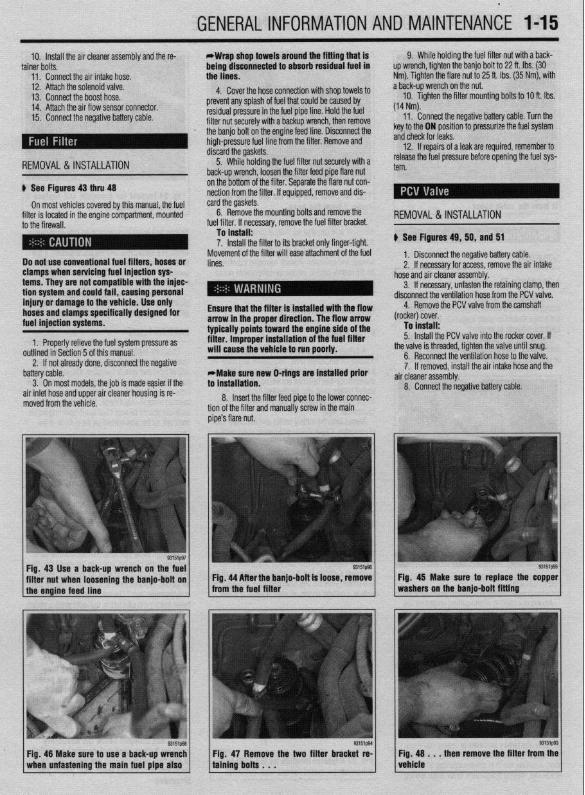
10. install the air cleaner assembly and the re- *Wrap shop towels around the fitting that is tainer bolts. being dtsconnected to absorb residual fuel in
11. Connect the air intake hose. the lines.
9. While holding the fuel filter nut with aback- up wrench, tighten the banjo bolt to 22 ft. Ibs. (30 Nm). Tighten the flare nut to 25 ft. Ibs. (35 Nm), with
12. Attach the solenoid valve. 4. Cover the hose connection with shop towels to a back-up wrench on the nut. 13. Connect the boost hose. 14. Attach the air flow sensor connector. prevent any splash of fuel that could be caused by 10. Tighten the filter mounting bolts to 10 ft. Ibs.
residual pressure in the fuel pipe line. Hold the fuel (14 Nm). 15. Connect the negative battery cable. 11. \ filter nut securely with a backup wrench, then remove Connect the negative battery cable. Turn the
REMOVAL &INSTALLATION
the banjo bolt on the engine feed line. Disconnect the high-pressure fuel line from the filter. Remove and discard the gaskets.
5. While holding the fuel filter nut securely with a back-up wrench, loosen the filter feed pipe flare nut
key to the ON position to pressurize the fuel system and check for leaks.
12. If repairs of a leak are required, remember to release the fuel pressure before opening the fuel sys- tern.
u See Figures 43 thru 48
On most vehicles covered by this manual, the fuel filter is located in the engine compartment, mounted to the firewall.
Do not use conventional fuel filters, hoses or clamps when servicing fuel injection sys terns. They are not compatible with the injec- tion system and could fail, causing personal injury or damage to the vehicle. Use only hoses and clamps specifically designed for fuel injection systems.
1. Properly relieve the fuel system pressure as outlined in Section 5 of this manual.
on the bottom of the filter. Separate the flare nut con- nection from the filter. If equipped, remove and dis- card the gaskets.
6. Remove the mounting bolts and remove . ,,,. ,. .a r I,.,< I the ruer rrrter. II necessary, remove me ruer rrrrer oracket.
To install: 7. Install the filter to its bracket only finger-tight.
Movement of the filter will ease attachment of the fuel lines.
Ensure that the filter is installed with the flow arrow in the proper direction. The flow arrow typically points toward the engine side of the filter. improper installation of the fuel filter will cause the vehicle to run poorly.
2. If not already done, disconnect the negative
REMOVAL&INSTALLATION
u See Figures 49, 50, and 51
1, Disconnect the negative battery cable. 2. If necessary for access, remove the air intake
hose and air cleaner assembly. 3. If necessary, unfasten the retaining clamp, then
disconnect the ventilation hose from the PCV valve. 4. Remove the PCV valve from the camshaft
(rocker) cover. To install: 5. Install the PCV valve into the rocker cover. If
the valve is threaded, tighten the valve until snug.
battery cable. 3. On most models. the iob is made easier if the
air inlet hose and upper air cleaner housing is re- moved from the vehicle.
*Make sure new O-rings are installed prior to installation.
8. Insert the filter feed pipe to the lower connec- tion of the filter and manually screw in the main pipe’s flare nut.
6. Reconnect the ventilation hose to the valve. 7. If removed, install the air intake hose and the
a .ir cleaner assembly. 8. Connect the negative battery cable.
Fig. 43 Use a back-up wrench on the fuel I I
93151@3
filter nut when loosening the banjo-bolt on Fig. 44 After the banjo-bolt is loose, remove I 1 the engine feed line - from the fuel filter
93151p93
Fig. 48 Make sure to use a back-up wrench 1 when unfastening the main fuel pipe also 1
Fig. 47 Remove the two filter bracket re- taining bolts . . .
Fig. 45 Make sure to replace the copper washers on the banjo-bolt fitting
Fig. 48 . . . then remove the filter from the vehicle

*
l-16 GENERALINFORMATIONAND MAINTENANCE
Fig. 49 Grasp the valve and gently remove Fig. 50 Twist and pull on the valve to re- it from the valve cover move it from the hose
Fig. 51 Inspect the grommet and replace if cracked or leaking oil
SERVICING
corrosive acid can also eat away at components un- der the hood.
Always visually inspect the battery case for cracks, leakage and corrosion. A white corrosive substance
u See Figure 52
The evaporative canister requires no periodic ser- vicing. However, a careful inspection of the canister and hoses should be made frequently, Replace dam-
on the battery case or on nearby components would indicate a leaking or cracked battery. If the battery is cracked, it should be replaced immediately.
GENERALMAINTENANCE '_
devices that increase parasitic load may discharge a battery sooner. If the vehicle is to be stored for 6-B weeks in a secure area and the alarm system, if pre- sent, is not necessary, the negative battery cable should be disconnected at the onset of storage to protect the battery charge.
Remember that constantly discharging and recharging will shorten battery life. Take rare not to allow a battery to be needlessly discharged.
aged components as required. The canister is typically located under one of the
front fenders, however on some later models it may be under the rear of the vehicle, near the gas tank,
r on most models
# See Figure 53
A battery that is not sealed must be checked peri- odically for electrolyte level. You cannot add water to a sealed maintenance-free battery (though not all maintenance-free batteries are sealed); however, a sealed battery must also be checked for proper elec- trolyte level, as indicated by the color of the built-in hydrometer “eye.”
Always keep the battery cables and terminals free of corrosion. Check these components about once a year. Refer to the removal, installation and cleaning procedures outlined in this section,
Keep the top of the battery clean, as a film of dirt can help completely discharge a battery that is not used for long periods. A solution of baking soda and water may be used for cleaning, but be careful to flush this off with clear water. DO NOT let any of the solution into the filler holes. Baking soda neutralizes battery acid and will de-activate a battery cell.
Batteries in vehicles which are not operated on a regular basis can fall victim to parasitic loads (small
BA-ITERY FLUID
Check the battery electrolyte level at least once a month. or more often in hot weather or during peri- ods of extended vehicle operation. On non-sealed batteries, the level can be checked either through the case on translucent batteries or by removing the cell caps on opaque-cased types. The electrolyte level in each cell should be kept filled to the split ring inside each ceil, or the line marked on the outside of the case.
If the level is low, add only distilled water through the opening until the level is correct. Each cell is sep- arate from the others, so each must be checked and filled individuallv. Distilled water should be used, be- cause the chemicals and minerals found in most drinking water are harmful to the battery and could significantly shorten its life.
If water is added in freezing weather, the vehicle should be driven several miles to allow the water to mix with the electrolyte. Otherwise, the battery could freeze.
current drains which are constantly drawing current from the battery). Normal parasitic loads may drain a
Although some maintenance-free batteries have removable cell caos for access to the electrolyte, the
cause a short circuit, leading to sparks and possible personal injury.
Do not smoke, have an open flame or create sparks near a battery; the gases contained in the bat- tery are very explosive and, if ignited, could cause se- vere injury or death.
All batteries, regardless of type, should be care- fully secured by a battery hold-down device. If this is not done, the battery terminals or casing may crack from stress applied to the battery during vehicle oper- ation. A battery which is not secured may allow acid to leak out, making it discharge faster; such leaking
m / built-in hydrometer. . \
*Although the readings from built-in hy- drometers found in sealed batteries may vary, a green eye usually indicates a prop erly charged battery with sufficient fluid level. A dark eye is normally an indicator of a battery wlth sufficient fluid, but one which may be low in charge. And a light or yellow eye is usually an indication that electrolyte supply has dropped below the necessary
tcu1@32
Fig. 53 A typical location for the built-in hv- level for battery (and hydrometer) operation.
drometer on maintenan ce-free batteries ’ I In this last case. sealed batteries with an in- sufficient electrolyte level must usually be
’ discarded.

G,ENERALlNFORMATlONAND MAINTENANCE l-17
Fig. 54 On non-maintenance-free batteries, the fluid level can be checked through the Fig. 55 If the fluid level is low, add only dis-
1 case on translucent models; the cell caps 1 must be removed on other models 1
1 tilled water through the opening until the 1 level is correct
Checking the Specific Gravity
A hydrometer is required to check the specific
\ # See Figures 54, 55, and 56
gravity on all batteries that are not maintenance-free. On batteries that are maintenance-free, the soecific gravity is checked by observing the built-in hydrome- ter “eye” on the top of the battery case. Check with your battery’s manufacturer for proper interpretation of its built-in hvdrometer readinas.
gravity of the battery. It should be between 1.20 and
As stated earlier, the specific gravity of a battery’s electrolyte level can be u
1.26 on the gravity scale. Most auto supply stores
sed as an indication of bat- tery charge. At least once
carry a variety of inexpensive battery testing hydrom-
? a year, check the specific
eters. These can be used on any non-sealed battery , , , ,, .,, . . IO rest me specmc gravny in each cell.
The battery testing hydrometer has a squeeze bulb at one end and a nozzle at the other. Battery electrolyte
the hydrometer until the float is lifted -he specific gravity is then read by not- n of the float. If gravity is low in one or mg tne posrtro
Battery electrolyte contains sulfuric acid. If you should splash any on your skin or in your eyes, flush the affected area with plenty of clear water. If it lands in your eyes, get med- ical help immediately.
The fluid (sulfuric acid solution) contained in the battery cells will tell you many things about the con- dition of the battery. Because the cell plates must be kept submerged below the fluid level in order to op- erate, maintaining the fluid level is extremely impor- tant. And. because the soecific aravitv of the acid is an indication of electrical charge, testing the fluid can be an aid in determining if the battery must be re- placed. A battery in a vehicle with a properly operat- ing charging system should require little mainte- nance, but careful, periodic inspection should reveal problems before they leave you stranded.
Fig. 57 Maintenance is performed with Fig. 58 The underside of this special bat- household items and with special tools like tery tool has a wire brush to clean post ter-
I this post cleaner I 1 minals
Fig. 56 Check the specific gravity of the bat- tery’s electrolyte with a hydrometer
more cells, the battery should be slowly charged and Lhecked aqain to see if the aravitv has come UP. Gen- erally, if affer charging, the specific gravity between any two cells varies more than 50 points (0.50) the battery should be replaced, as it can no longer produce suffi- cient voltage to guarantee proper operation.
CABLES
) See Figures 57, 56, 69, 60, and 61
Once a year (or as necessary), the battery termi- nals and the cable clamps should be cleaned. Loosen

l
1-18 GENERALINFORMATIONAND MAINTENANCE
the clamps and remove the cables, negative cable first. On batteries with posts on top, the use of a puller specially made for this purpose is recom- mended. These are inexoensive and available in most
alternator or turn the adjusting bolt to adjust belt ten- sion. Once the desired value is reached, secure the bolt or locknut and recheck tension.
d”t” lJdlL> X”lt;>. 31°C LtXlllllldl lJdllt2)’ MLJIC, dlt’ X-
cured with a small bolt. ST& I REMOVAL &INSTALLATION
Clean the cable clamps and the battery terminal I
with a wire brush, until all corrosion, grease, etc., is removed and the metal is shinv. It is esneciallv imnnr- tant to c knife is useful nere), since a smart material or oxidation there will pre
Clean the cable clamps and the battery terminal with a wire brush, until all corrosion, grease, etc., is removed and the metal is shiny. It is especially impor- tant to clean the inside of the clamp thoroughly (an old knife is useful here), since a small deposit of foreign material or oxidation there will prevent a sound electri- cal connection and inhibit either starting or charging. Special tools are available for cleaning these parts, one type for conventional top post batteries and an- other type for side terminal batteries. It is also a good idea to apply some dielectric grease to the terminal, as this will aid in the prevention of corrosion,
After the clamps and terminals are clean, reinstall the cables, negative cable last; DO NOT hammer the clamps onto battery posts. Tighten the clamps se- curely, but do not distort them. Give the clamps and terminals a thin external coating of grease after in- stallation, to retard corrosion.
Check the cables at the same time that the terminals are cleaned. If the cable insulation is cracked or bro- ken, or if the ends are frayed, the cable should be re- placed with a new cable of the same length and gauge.
CHARGING
the cables, negative cable last; DO NOT hammer the
curely, but do not distort them. Give the clamps and terminals a thin external coating of grease after in- stallation, to retard corrosion.
Check the cables at the same time that the terminals are cleaned. If the cable insulation is cracked or bro- ken, or if the ends are frayed, the cable should be re- placed with a new cable of the same length and aauae.
CHARGING
Fig. 62 mere are typically 3 types of ac- cessory drive belts found on vehicles today
1. Loosen the alternator support nut. 2. Loosen the adjuster lock bolt. 3. Rotate the adjuster bolt counter clockwise to I .I , . . . * . .
I
Tn i”et*ll*
Fig. 62 There are typically 3 types of ac-
Fig. 64 Deep cracks in this belt will cause flex, building up heat that will eventually
11, 1.8L, 2.OL and 2.4L Engines
cal connection and inhibit either starting or charging. Special tools are available for cleaning these parts, one type for conventional top post batteries and an- other type for side terminal batterin, I+ if QI@* 3 nnnd idea to apply some dielectric grr this will aid in the prevention of ,,vIIuaIUII.
After the clamps and terminals are clean, reinstall
1.5L, 1.6
AL TERNA TOR BE1 T
e See Figures 67,68, and 69
1. Loosen the alternator support nut. 2. Loosen the adjuster lock bolt. 3. Rotate the adjuster bolt counter clockwise to
release the tension on the belt. 4. Remove the belt. To install: 5. Install the belt on the pulleys. 6. Rotate the adjuster bolt clockwise until the
proper tension is reached. 7. Tighten the adjuster lock bolt and the alternator
support nut.
POWER STEERING BELT
8 See Figures 70 and 71
1. Remove the alternator belt as described above. 2. Loosen the power steering pump adjusting
bolts. 3. Remove the power steering oumo fixed bolt on
R Rntatn the cxiillrtm hnit A&+,& until the
r -r- .- .- ._.. ._ .______ 7. Tighten the adjuster lock bolt and the alternator
support nut.
POWER STEERING BELT
1 ..“‘.I ““..Y...Y up II”“. ..IU. ..m.*
1 lead to belt failure V.
I I
The chemical reaction which takes place in
- 1 the rear of the bracket. 4. Rotate the pump toward the engine and remove
the belt. all batteries generates explosive hydrogen gas. A spark can cause the battery to explode and splash acid. To avoid serious personal injury, be sure there is proper ventilation and take appropriate fire safety precautions when connecting, disconnecting, or charging a bat- tery and when using jumper cables.
To fnstall: 5. Install the belt on the pulleys.
A battery should be charged at a slow rate to keep the plates inside from getting too hot. However, if some maintenance-free batteries are allowed to dis- charge until they are almost “dead,” they may have to be charged at a high rate to bring them back to “life.” Always follow the charger manufacturers instructions on charging the battery.
85 The cover of this belt ex- Fig. is worn,
REPLACEMENT
When it becomes necessary to reolace thn haeoN ‘” yyL’“‘J’ I or oreMer select one with an amperage rating equal tc . a ----
than the battery originally installed. Deterioration and just plain aging of the battery cables, starter motor, and associated wires makes the battery’s job harder in successive years. The slow increase in electrical resistance over time makes it prudent to install a new battery with a greater capacity than the old.
1 Fig. 67 Loosen the adjuster lock bolt . . . I ‘-
I -. -_ tm1217
Fig. 66 Installing too wide a belt can resylt in serious belt wear and/or breakage
the belt and run outward. All worn or damaged drive belts should be replaced immediately. It is best to re- place all drive belts at one time, as a preventive
uring this service operation. maintenance measure, d
- ADJUSTMENT : *
INSPECTION Excessive belt tension will cause damage to the al-
e See Figures 62, 83, 64, 65, and 88
Inspect the belts for signs of glazing or cracking. A glazed belt will be perfectly smooth from slippage, while a good belt will have a slight texture of fabric visible. Cracks will usually start at the inner edge of
pulley bearings, while, on It tension will Droduce slin
ternator and water pump the other hand, loose be r ------ r and premature wear on the belt. Therefore, be sure to adjust the belt tension to the proper level.
To adjust the tension ’ ’ ’ ” ’ ‘* adjusting bolt or fixing b alternator bracket or tens
on a onve Den. loosen me I
Fig. 68 . . . then from the engine
remove the alternator
bolt locknut on the alternator, iion pulley. Then move the

GENERAL INFORMATION AND MAlNTENANdE l-19
792UQ4
Fig. 69 Accessory V-belt routing-Mii subishf 1.6L, 1.6L,-1.6L, 2.OL and 2.4L en gines
33151PM
Fig. 70 After the adjusting and fixed bolt! are loosened, rotate the pump . . .
/ F$71t immtl$mm&a the power :::
6. Rotate the pump until the proper tension is reached.
7. Tighten the adjusting bolts on the pump. 8. Tighten the fixed bolt on the rear of the bracket. 9. Install the alternator belt.
A/r: COMPRESSOIl BEL f 1. Loosen the tension oullev and remove the belt. 2. The installation is the reverse of the removal.
.3.gL DGHC, 3.OL SOHC (Gaiant models only) and 3.5L Engines
4. Remove the belt. To install: 5. Install the belt on the crankshaft and alternator
pulleys. 6. Using the adjusting bolt on the tensioner,
tighten the belt to the desired tension. 7. Tighten the fixing nut to hold the adjustment. 8. Install the undercover and lower the vehicle to _,
the tloor. 9. Connect the negative battery cable.
POWER SliEERlNG BEL f
6 See Figures 72 and 73 1. Disconnect the neaative batteN cah+P
-I Wait at least 60 seconds after the negative battery cable is disconnected to prevent poS- sibie deployment of the air bag.
2. Raise and safely support the vehicle and re- mob re the undercover.
3. Remove the alternator and NC compressor belt.
4. Lower the vehicle and remove the cruise con- trol oumn link iW%mblV.
79244Q.37 -- I-- r ---- - _I
Fig. 72 Serpentine belt routing-Mitsubishi 5. Place the power steering hose under the oil
reservoir. 3.OL engines (except 1696-00 Galant mod- 6. Loosen the tension pulley fixing bolts and re- els)
Generator pulP
1 move the power steering pump drive belt. To install:
1 7. install the Dower steerina oumu r+r+v~ hp++ 8. Insert an extension bar &eoufvaik;;t”f;;id‘he
opening at the end of the tension pulley bracket and pivot the pulley to apply tension to the belt.
9. Tighten the fixing bolts. 10. Raise the vehicle and install the alternator and compressor belt.
Il. Install the undercover and lower +hfi vph+r+p .I,., .VII.“.Y. 12. Connect the negative battery cable.
I 3.OL SGHC (Diamante Models Onivl Enotne
I
,r ”
1. Disconnect the negative battery cable. 2.’ Loosen the lockbolt on the face nf the A/C _ __.-
tensioner pulley. 3 Turn the adiustina bolt of the A/C +fincrnner
pulley to loosen the tension of the A/C belt. 4. Remove the A/C compressor belt. 5. Loosen the locknut on the face of the power
to loosen the tc 7. Remov
Fig. 73 Accessory V-belt routing-Mitsubishi 3.5L and 1996-00 3.OL SOHC Galant en- gines
steering/alternator tensloner pulley. 6. Turn the adjusting bolt of the tensioner pulley
msion of the belt. ‘e the power steering/alternator belt.
To install: 8. Install the power steering/alternator belt first .* .* . ,^ ssor drive belt. ana tnen tne A/ti compre: 9. Adjust the belts t+
ing the adjusting bolts anu II~IIWII pueey tlxmg I the proper tension by turn- A.:-L I-..-.. I,^, .’
nut/bolt. 10. Tighten the mounting nut of the power steer-
ing/alternator tensioner pulley to 36 ft. Ibs. (50 Nm). Wait at least 60 seconds after the negative battery cable is disconnected to prevent pos- sible deployment of the air bag.
-The manufacturer does not provide a torque specification for the bolt that secures A/C tensioner pulley.
2. Raise and safely support the vehicle and re- 11. Connect the negative battery cable. move the front undercover.
3. Loosen the tension pulley fixing nut and relieve the tension on the belt by turning the adjusting bolt.

.
l-20 GENERALINFORMATIONAND MAINTENANCE
INSPECTION
# See Figures 74 thru 81
All engines covered by this manual utilize timing belts to drive the camshaft from the crankshafts turn- ing motion and to maintain proper valve timing. Some manufacturers schedule periodic timing belt replacement to assure optimum engine performance, to make sure the motorist is never stranded should the belt break (as the engine will stop instantly) and for some (manufacturers with interference motors) to prevent the possibility of severe internal engine dam- age St10Ula the Delt break.
Although the 1.5L and 1.8L engines are not listed as an interference motors (it is not listed by the man- ufacturer as a motor whose valves might contact the pistons if the camshaft was rotated separately from the crankshaft) the first 2 reasons for periodic re- placement still apply and the timing belt should be replaced at 60,000 miles (96,000 km). The 1.6L, 2.01,2.4L, 3.OL, and 35L engines are listed as inter- ference motors, so the timing belt MUST be replaced at 60,000 miles (96,000 km) to avoid severe engine damage if the belt should break.
But whether or not you decide to replace the tim- ing belt in the manufacturers schedule, you would be wise to check it periodically to make sure it has not become damaged or worn. Generally speaking, a se- verelv worn belt mav cause enaine oerformance to drop~dramatically, but a damaged belt (which could give out suddenly) may not give as much warning. In general, any time the engine timing cover(s) is (are) removed you should inspect the belt for premature parting, severe cracks or missing teeth. Also, an ac- cess plug is provided in the upper portion of the tim- ing cover so that camshaft timing can be checked without cover removal. If timing is found to be off, cover removal and further belt inspection or replace- ment is necessary.
tml245
Fig. 76 look for noticeable cracks or wear on the belt face _
For the timing belt removal and installation proce- dure, please refer to Section 3 of this manual.
Fig. 74 Check for premature parting of the belt
INSPECTION
. 75 Check if the teeth are cracked or
fig. 77 You may only have damage on one side of the belt; if so, the guide could be the culprit
b See Figures 82,8S, 84, and 85 .
Upper and lower radiator hoses, along with the heater hoses, should be checked for deterioration, leaks and loose hose clamps at least every 30,000 miles (48,000 km). It is also wise to check the hoses periodically in early spring and at the beginning of the fall or winter when you are performing other maintenance. A quick visual inspection could dis- cover a weakened hose which might have left you stranded if it had remained unrepaired.
Whenever you are checking the hoses, make sure the engine and cooling system are cold. Visually in- spect for cracking, rotting or collapsed hoses, and w- place as necessary. Run your hand along the length of the hose. If a weak or swollen spot is noted when squeezing the hose wall, the hose should be re-
Fig. 78 Foreign materials can get in be- Fig. 79 Inspect the timing belt for c tween the teeth and cause damage fraying, glazing or damage of any kind
Fig. 80 Damage on only one side of the tim- I I
Fig. 81 ALWAYS replace the timing belt at ing belt may indicate a faulty guide the interval specified by the manufacturer
, L
placed.

GENERALINFORMATIONAND MAINTENANCE l-21
IWSIZXJ
FM. 83 A hose clamn that is taa tiaht can Fig. 82 The cracks developing along this hose are a result of age-related hardening
caise older hoses td separate and ‘iear on either side of the clamp
lCCS1221
Fig. 84 A soft spongy hose (identifiable by
1 the swollen section) will eventually burst and should be replaced
IEMOVAL &,INSTALLATION '
1. Remove the radiator pressure cap. her of the sorina tension tvoe (which reouire oliers 3 squeeze the 6bs and loosenj or of the’screw ten- ion type (which require screw or hex drivers to oosen). Pull the clamps back on the hose away from he connection. Never remove the pressure cap while the en-
gine is running, or personal injury from scalding hot coolant or steam may result. If possible, wait until the engine has cooled to remove the pressure cap. If this is not possi- ble, wrap a thick cloth around the pressure cap and turn it slowly to the stop. Step back while the pressure is released from the cool- ing system. When you are sure all the pres- sure has been released, use the cloth to turn and remove the cao.
2. Position a clean container under the radiator and/or engine draincock or plug, then open the drain and allow the cooling system to drain to an appropri- ate level. For some upper hoses, only a little coolant must be drained. To remove hoses positioned lower on the engine, such as a lower radiator hose, the en- tire cooling system must be emptied.
When draining coolant, keep in mind that cats and dogs are attracted by ethylene gly- col antifreeze, and are quite likely to drink any that is left in an uncovered container or in puddles on the ground. This will prove fa- tal in sufficient quantity. Always drain coolant into a sealable container. Coolant may be reused unless it is contaminated or several years old.
9. Close the radiator or engine drains and prop- erly refill the cooling system with the clean drained engine coolant or a suitable mixture of ethylene gly- cot coolant and water.
10. If available, install a pressure tester and check for leaks. If a pressure tester is not available, run the engine until normal operating temperature is reached (allowing the system to naturally pressurize), then check for leaks.
If you are checking for leaks with the system at normal operating temperature, BE EX- TREMELY CAREFUL not to touch any moving or hot engine parts. Once temperature has been reached. shut the enaine OFF. and
Fig. 85 Hoses are likely to deteriorate from the inside if the cooling system is not peri- odically flushed
check for leaks around the-hose fittings and connections which were removed earlier.
INSPECTION
b See Figures 88 and 87
The CV (Constant Velocity) boots should be checked for damage each time the oil is changed and any other time the vehicle is raised for service. These boots keep water, grime, dirt and other damaging matter from entering the CV-joints. Any of these could cause early CV-joint failure which can be ex- pensive to repair. Heavy grease thrown around the in- side of the front wheel(s) and on the brake caliper/drum can be an indication of a torn boot. Thorouahlv check the boots for missina clamos and
3. Loosen the hose clamps at each end of the rose requiring replacement. Clamps are usually ei-
4. Twist, pull and slide the hose off the fitting, sking care not to damage the neck of the component rom which the hose is being removed.
*If the hose is stuck at the connection, do lot try to insert a screwdriver or other sharp ool under the hose end in an eff art to free it, IS the connection and/or hose may become lamaged. Heater connections especially nay be easily damaged by such a procedure. f the hose is to be replaced, use a single- !dged razor blade to make a slice along the lortion of the hose which is stuck on the con- section, perpendicular to the end of the lose. 00 not cut deep so as to prevent dam- aging the connection. The hose can then be keeled from the connection and discarded.
Fig. 86 CV-boots must be inspected period-
5.. Clean both hose mounting connections. In- ,pect the condition of the hose clamps and replace hem, if necessary.
To install: 6. Dip the ends of the new hose into clean en-
fine coolant to ease installation. 7. Slide the clamps over the replacement hose,
hen slide the hose ends over the connections into rosition.
8. Position and secure the clamps at least l/d in. 6.35mm) from the ends of the hose. Make sure they Ire located beyond the raised bead of the connector.
l-22 GENERALINFORMATIONAND MAINTENANCE tears. If the boot is damaged, it should be replaced trode is to the block’s cooling passages) the cooler it your driving is long distance, high speed travel, use a immediately. Please refer to Section 7 for procedures. will operate. A plug that absorbs little heat and re- colder plug; if most of your driving is stop and go,
mains too cool will quickly accumulate deposits of use a hotter plug. Original equipment plugs are gen- oil and carbon since it is not hot enough to burn erally a good compromise between the 2 styles and them off. This leads to plug fouling and consequently most people never have the need to change their to misfiring. A plug that absorbs too much heat will plugs from the factory-recommended heat range.
ti See Figure 88 have no deposits but, due to the excessive heat, the ,electrodes will burn away quickly and might possibly REMOVAL &INSTALLATION
A typical spark plug consists of a metal shell sur- lead to preignition or other ignition problems. Preig- rounding a ceramic insulator. A metal electrode ex- nition takes place when plug tips get so hot that they ti See Figures 90 thru 95 tends downward through the center of the insulator glow sufficiently to ignite the air/fuel mixture before and protrudes a small distance. Located at the end of the actual spark occurs. This early ignition will usu- A set of spark plugs usually requires replacement the plug and attached to the side of the outer metal ally cause a pinging during low speeds and heavy after about 20,000-30,000 miles (32,000-48,000 shell is the side electrode. The side electrode bends loads. km), depending on your style of driving. In normal in at a 90” angle so that its tip is just past and paral- The general rule of thumb for choosing the correct operation plug gap increases about 0.001 in. lel to the tio of the center electrode. The distance be- heat range when picking a spark plug is: if most of (0.025mrn) for every 2,500 miles (4,000 km). As the tween these two electrodes (measured in thousandths of an inch or hundredths of a millimeter) is called the spark piug gap.
The spark plug does not produce a spark, but in- steed provides a gap across which the current can arc. The coil produces anywhere from 20,000 to 50,000 volts (depending on the type and application) which travels through the wires to the spark plugs. The current passes along the center electrode and jumps the gap to the side electrode, and in doing so, ignites the air/fuel mixture in the combustion charn- ber.
SPARKPLUG HEATRANGE
ti See Figure 89
Spark plug heat range is the ability of the plug to dissipate heat. The longer the insulator (or the farther
INSULATOR CRACKS OFTEN OCCUR HERE
SIDE ELECTRODE ENTER ELECTRODE: (SEND TO ADJUST GAP) FILE FLAT WHEN
ADJUSTING GAP; DO NOT BEND
Fig. 88 Cross-section of a spark plug
it extends into the engine), the hotter the plug will operate; the shorter the insulator (the closer the elec-
Fig. 90 Carefully twist the boot end of the I spark plug wire and withdraw the spark plug wire boot from the cylinder head
Fig. 92 A locking extension such as this is extremely helpful when removing spark plugs that are centrally located in the cyhn-
Fig. 94 . . . then carefully withdraw the spark plug from the engine
Fig. 91 A special spark plug socket with a rubber insert is required to remove the spark plugs. Typically the spark plugs re- quire a Ya spark plug socket
Fig, 93 Using the appropriate sized spark plug socket, necessary extensions and drive tools, loosen the spark plug . . .
93151ptxl
Fig. 95 After removing the plug from the en- gine, inspect it using the spark plug condi- tion chart in this section to determine the running condition of your engine
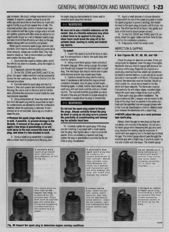
t
GENERALINFORMATIONAND MAINTENANCE l-23
gap increases, the plug’s voltage requirement also in- creases. It requires a greater voltage to jump the
the spark plug counterclockwise to loosen and re- move the spark plug from the bore.
wider gap and about &o to three times as much volt- age to fire the plug at high speeds than at idle. The improved air/fuel ratio control of modern fuel injec- tion combined with the higher voltage output of mod- Be sure not to use a flexible extension on the place. The click may be felt or heard, then gently pull
ern ignition systems will often allow an engine to run socket. Use of a flexible extension may allow back on the boot to assure proper contact.
.___. . _ significantly longer on a set of standard spark plugs, a shear force to be agptf’ ea to me plug. A
12. On the 3.OL fSOHC and DOHC) and 3.5L en- LL_ _I___ -u I_ IL-
but keep in mind that efficiency will drop as the gap shear force could break tne pug on III me tion 3 for the installation procedure. widens (along with fuel economy and power). cylinder head, leading to costly and frustrat- 13. If equipped, install the center cover.
When you’re removing spark plugs, work on one ing repairs. at a time. Don’t start by removing the plug wires all at once, because, unless you number them, they may To install:
INSPECTION & GAPPING
11. Apply a small amount of silicone dielectric compound to the end of the spark plug lead or inside the spark plug boot to prevent sticking, then install the boot to the spark plug and push until it clicks into
gines, install the upper intake manifold. Refer to Sec-
,,Y” ..1111 uy”’
1 the neaative bat&v cable and if
become mixed up. Take a minute before you begin and number the wrrpc with +sne
1. Disconnect. ~~.~ --..-., -..-.-, -..- thevehicle has been run recently, allow the engine to thoroughly cool.
2. If equipped, remove the center cover. 3. On the 3.OL (SOHC and DOHC) and 3.5L en-
gines, the upper intake manifold must be removed to access the rear spark plugs. Refer to Section 3 for the removal procedure.
4. Carefully twist the spark plug wire boot to loosen it, then pull upward and remove the boot from the plug. Be sure to pull on the boot and not on the wire, otherwise the connector located inside the boot may become separated.
5. Using compressed air, blow any water or de- bris from the spark plug well to assure that no harm- ful contaminants are allowed to enter the combustion chamber when the spark plug is removed. If com- pressed air is not available, use a raa or a brush to
must be replaced. Check the plugs for deposits and wear, If they are
7. Inspect the spark plug boot for tears or dam- age. If.a damaged boot is found, the spark plug wire
8. Using a wire feelergauge, check and adjust the spark plug gap. When using a gauge, the proper size should pass between the electrodes with a slight drag. The next larger size should not be able to pass while the next smaller size should pass freely.
9. Carefully thread the plug into the bore by hand. If resistance is felt before the plug is almost completely threaded, back the plug out and begin threading again. In small, hard to reach areas, an old spark plug wire and boot could be used as a thread- ing tool. The boot will hold the plug while you twist the end of the wire and the wire is supple enough to twist before it would allow the plug to crossthread.
Do not use the spark plug sock? l -- K-rrA tha nhme Alwmm rarntdlv thw
GL I” IlllGa”
the possibility of crossthreading and damag-
lad the plug . ..Y f..“YY. rn”Y,‘““mY*“.‘, .I**”
by hand or using an old plug wire to prevent
ing the cylinder head bore.
10. Carefully tighten the spark plug. If the plug you are installing is equipped with a crush washer, seat the plug, then tighten about I/, turn to crush the washer. If you are installing a tapered seat plug, tighten the plug to specifications provided by the ve- hicle or plug manufacturer.
b See Figures 98, 97, 98, 99, and 100
not going to be replaced, clean the plugs thoroughly. Remember that any kind of deposit will decrease the efficiency of the plug. Plugs can be cleaned on a spark plug cleaning machine, which can sometimes be found in service stations, or you can do an accept- able job of cleaning with a stiff brush. If the plugs are’ cleaned, the electrodes must be filed flat. Use an ig- nition points file, not an emery board or the like, which will leave deposits. The electrodes must be filed perfectly flat with sharp edges; rounded edges reduce the spark plug voltage by as much as 50%.
Check spark plug gap before installation. The ground electrode (the L-shaped one connected to the body of the plug) must be parallel to the center elec- trode and the specified size wire gauge (please refer to the Tune-Up Specifications chart for details) must pass between the electrodes with a slight drag: *,NEVER adjust the gap on a used platinum . clean the area.
*Remove the spark plugs when the engine is cold, if possible, to prevent damage to the threads. If removal of the plugs is difficult, apply a few drops of penetrating oil or sili- cone spray to the area around the base of the plug, and allow it a few minutes to work.
6. Using a spark plug socket that is equipped with a rubber insert to properly hold the plug, turn
type spark plug. Always check the gap on new plugs as they are
not always set correctly at the factory. Do not use a flat feeler gauge when measuring the gap on a used plug, because the reading may be inaccurate. A round-wire type gapping tool is the best way to check the gap. The correct gauge should pass through the electrode gap with a slight drag. If you’re in doubt, try one size smaller and one laraer. The smaller aauqe
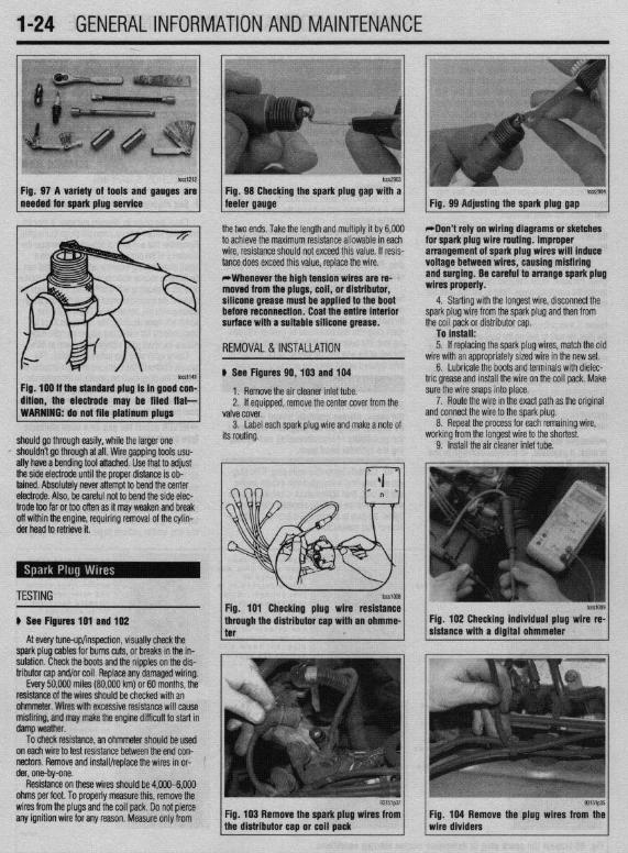
l-24 GENERALINFORMATIONAND MAINTENANCE
b%slZl2
Fig. 97 A variety of tools and gauges are needed for spark plug service
tm2903
Fig. 98 Checking the spark plug @au with a tccs2904
feeler gauge. - Fig. 99 Adjusting the spark plug gap
ig. 100 If the standard plug Is in good con- ftlon, the electrode may be filed flat-
the two ends. Take the length and multiply it by 6,000 to achieve the maximum resistance allowable in each wire, resistance should not exceed this value. If resis- tance does exceed this value, replace the wire. *Whenever the high tension wires are re- ’ moved from the plugs, coil, or distributor, silicone grease must be applied to the boot before reconnection. Coat the entire Interior surface with a suitable silicone grease.
REMOVAL &INSTALLATION
# See Figures 90,103 and 104
1. Remove the air cleaner inlet tube. 2. If eouiooed, remove the center cover from the
WARNING: do not file platinum plugs valve covei. 3. Label each spark plug wire and make a note of
should go through easily, while the larger one its routing. I’ shouldn’t go through at all. Wire gapping tools usu-
ally have a bending tool attached. Use that to adjust the side electrode until the proper distance is ob- \ tained. Absolutely never attempt to bend the center electrode. Also, be careful not to bend the side elec-
*Don’t rely on wiring diagrams or sketches for spark plug wire routing. Improper arrangement of spark plug wires will induce voltage between wires, causing misfiring and surging. Be careful to arrange spark plug wires properly.
4. Starting with the longest wire, disconnect the spark plug wire from the spark plug and then from the coil pack or distributor cap.
To install: 5. If replacing the spark plug wires, match the olc
wire with an appropriately sized wire in the new set. 6. Lubricate the boots and terminals with dielec-
tric grease and install the wire on the coil pack. Make sure the wire snaps into place.
a 7. Route the wire in the exact path as the original
nd connect the wire to the spark plug. 8. Repeat the process for each remaining wire,
iorking from the longest wire to the shortest. 9. Install the air cleaner inlet tube.
trode too far or too often as it may weaken and break off within the engine, requiring removal of the cylin- der head to retrieve it.
TESTING
# See Figures 191 and 102
At every tune-up/inspection, visually check the spark plug cables for burns cuts, or breaks in the in- sulation. Check the boots and the nipples on the dis- tributor cap and/or coil. Replace any damaged wiring.
Every 50,000 miles (80,000 km) or 60 months, the resistance of the wires should be checked with an ohmmeter. Wires with excessive resistance will cause misfiring, and may make the engine difficult to start in damp weather.
To check resistance, an ohmmeter should be used ’ on each wire to test resistance between the end con- nectors. Remove and install/replace the wires in or- ’ der, one-by-one.
Resistance on these wires should be 4,000-6,000 ohms per foot. To properly measure this, remove the wires from the plugs and the coil pack. Do not pierce any ignition wire for any reason. Measure only from Fig. 103 Remove the spark plug wires from
tcG1009
Fig. 102 Checking individual plug wire re- sistance with a digital ohmmeter
Fig. 104 Remove the plug wires from the wire dividers

GENERALINFORMATIONAND MAlNTENANdE 1-25
osen the distributor cap retain- Fig. 106. . . then remove the cap from the distributor
Fig. 107 Grasp the rotor and pull it straight off of the distributor shaft
REMOVAL &INSTALLATION
1. Disconnect the negative battery cable. *Depending on the reason for removing the distributor cap, it may make more sense to
Fig. 108 The rotor must be aligned correctly to the distributor shaft before installation
other physical damage. Make sure the distributor cap’s center button is free of damage. Check the cap terminals for dirt or corrosion. Always check the rotor blade and spring closely for damage. Replace any comoonents where damaae is found.
smmE ALGNME LOCATOR
b See Figures 105,106,107, and 108
GENERAL INFORMATION
b See Figures 111 and 112
Ignition timing is the measurement, in degrees of crankshaft rotation, of the point at which the spark plugs fire in each of the cylinders. It is measured in degrees before or after Top Dead Center (TDC) of the compression stroke.
Ideally, the air/fuel mixture in the cylinder will be ignited by the spark plug just as the piston passes
I 1
COMBUSTION ENDS 23’ ATDC
SPEED INCREASES
9ir&1$?6
Fig. 111 Advancing the ignition timing ’
CCURS COMBUSTION DC ENDS 23 ATDC
3. Remove the distributor cap retaining screws or clips and remove the cap from the distributor.
4. Note its installed position, then remove the ro- tor from the distributor shaft.
leave the spark plug wires attached. This is handy if you are testing spark plug wires, or if removal is necessary to access other com- ponents, and wire length allows you to repo- sition the cap out of the way.
2. Label and disconnect the spark plug wires from the distributor cao.
5. The installation is the reverse of the removal.
INSPECTION
u See Figures 109 and 110 9mg27
After removing the distributor cap and rotor, clean the components (both inside and outside of the cap) using soap and water. If compressed air is available, carefully dry the components (wearing safety gog- gles) or allow the parts to air dry. You can dry them with a clean, soft cloth, but don’t leave any lint or moisture behind.
Once the cap and rotor have been thoroughly Inspection points for the dis
Fig. 112 Retarding the tgnttion timing
cleaned, check for cracks, carbon tracks, burns or

.
1-26 GENERALINFORMATIONAND MAINTENANCE
TDC of the compression stroke. If this happens, the piston WIII be at the beginning of the power stroke just as the compressed and ignited air/fuel mixture forces the piston down and turns the crankshaft. Be- cause it takes a fraction of a second for the spark plug to ignite the mixture in the cylinder, the spark plug must fire a little before the piston reaches TDC. Otherwise, the mixture will not be completely ignited as the piston passes TDC and the full power of the explosion will not be used by the engine.
The timing measurement is given in degrees of crankshaft rotation before the piston reaches TDC (BTDC). If the setting for the ignition timing is 10” BTDC, each spark plug must fire 10 degrees before each piston reaches TDC. This only holds true, how- ever, when the engine is at idle speed. The combus- tion process must be complete by 23”ATDC to main- tain proper engine performance, fuel mileage, and low emissions.
As the engine speed increases, the pistons go faster. The spark plugs have to ignite the fuel even sooner if it IS to be completely ignited when the pis- ton reaches TDC. If the ignition is set too far ad- vanced (BTDC), the ignition and expansion of the fuel in the cylinder wtll occur too soon and tend to force the piston down while it is still traveling up. Thus causes pre ignition or “knockmg and pinging”. If the ignition spark is set too far retarded, or after TDC (ATDC), the piston will have already started on its way down when the fuel is ignited. The piston will be forced down for only a portion of its travel, resulting in poor engine performance and lack of power.
Timing marks or scales can be found on the rim of the crankshaft pulley and the timing cover. The marks on the pulley correspond to the posrtion of the piston in the No. 1 cylinder. A stroboscopic (dynamic) tim- ing light is hooked onto the No. 1 cylinder spark plug wrre. Every time the spark plug fires, the timing light flashes. By aiming the light at the timing marks while the engine is running, the exact position of the piston within the cylinder can be easily read (the flash of light makes the mark on the pulley appear to be standing still). Proper timing is indicated when the mark and scale are in specified alignment.
When checking timing with the engine run- ning, take care not to get the timing light wires tangled in the tan blades and/or drive belts.
INSPECTION &ADJUSTMENT
1990-96 Models
e See Figures 113 thru 119
1. Set the parking brake, start and run the engine until normal operating temperature is obtained. Keep all lights and accessories OFF and the front wheels straight-ahead. Place the transaxle in P for automatic transaxle or Neutral for manual transaxle.
2. If not at specification, set the idle speed to the correct level.
3. Turn the engine OFF. Remove the water- proof cover from the igmtion timing adjusting con- nector, and connect a jumper wire from this terminal
Fig. 113 Ignition timing adjustment con- nector-1990-92 Mirage with 1.5L engine
93151QM
Fig. 115 Ignition timing adjustment con- nectar-Galant with 2.OL engines
93151QO1
Fig. 117 Ignition timing adjustment con. nectar-1994-96 Galant
to a good ground. Refer to the corresponding illustra- tions for the correct location of the timing adjustment connector.
4. Connect a conventional power timing light to the No. 1 cylinder spark plug wire. Start the engine and run at idle.
5. Aim the timing light at the timing scale lo- cated near the crankshaft pulley.
6. Loosen the distributor or crank angle sensor hold-down nut just enough so the housing can be ro- tated.
7. Turn the housing in the proper direction until the specified timing is reached. Tighten the hold- down nut and recheck the timing. Turn the engine OFF.
8. Remove the jumper wire from the ignition timing adjusting terminal and install the water-proof cover.
9. Start the engine and check the actual timing (the timing without the terminal grounded). This reading should be approximately 5 degrees more than the basic timing. Actual timing may increase ac- cording to altitude. Also, actual timing may fluctuate because of slight variation accomplished by the ECU.
Fig. 114 Ignition timing adjustment con- nectar-Miracle with 1.6L enaine
CHECK CONNECTOR 93151QO!
Fig. 116 Ignition timing adjustment con. nectar-1992-96 Oiamante
93151gOB
Fig. 116 Ignition timing adjustment con- nector-1993-96 Mirage with 1.5L engine
Fig. 119 Ignition timing adjustment con- nector-1993-96 Mirage with 1.6L engine
As long as the basic timing is correct, the engine is timed correctly.
10. Turn the engine OFF. 11. Disconnect the timing apparatus and
tachometer.
1997-00 Models The ignition timing is controlled by the Engine
Control Module (ECM) and is not adjustable. How- ever it can be inspected using a scan tool.

GENERALINFORMATIONAND MAlNTENANdE I-27
ADJUSTMENT
u See Figures 120 and 121
The only engines that require periodic adjustment of the valves are the 1.5L engine in the 1990-95 Mi- rage and the 1.8L in the 1993-95 Mirage.
Incorrect valve clearance will cause noisy and/or unsteady engine operation, reduced engine output, and possible engine damage. Check the valve clearances and adjust as re- quired while the engine is hot.
1. Warm the engine to operating temperature. Turn the engine OFF. Disconnect the negative battery cable.
2. Remove all spark plugs so engine can be eas- ily turned by hand
3. Remove the valve cover. 4. Turn the crankshaft clockwise until the notch
on the pulley is aligned with the T mark on the timing belt lower cover. This brings both No. 1 and 4 cylin- der pistons to Top Dead Center (TDC).
5. Wiggle the rocker arms on No. 1 and 4 cylin- ders up and down to determine which cylinder is at TDC on the compression stroke. Both rocker arms should move if the piston in that cylinder is at TDC on the compression stroke.
6. Measure the valve clearance with a feeler gauge. When the No. 1 piston is at TDC on the com- pression stroke, check No. 1 intake and exhaust; No. 2 intake and exhaust. Then turn the crankshaft clock- wise 1 turn to bring No. 4 to TDC on its compression stroke. With No. 4 on TDC, compression stroke, check No. 2 exhaust and intake; and No. 4 intake and exhaust. Clearance is as follows:
1990-92 1.5L engine:
No.1 No.2 No.3 No.4
when engine is on TDC of cylinder 1 and (B) when engine is on TDC of cylinder 4
No.1 No.2 No.3 No.4
AA AA BB BB 93151g10
Fig. 121 Adjusting the valve clearance
l Exhaust valve: 0.0098 in. (0.25mm) screw. When at specification, tighten the locknut. Be l Intake valve: 0.0059 in. (0.15mm) 1993-95 1.5L engine:
sure to hold the screw securely in place when tight-
l Exhaust valve: 0.0098 in. (0.25mm) ening the locknut to prevent it from turning when
* Intake valve: 0.008 in. (0.20mm) tightening the locknut. Tightening torque of the lock- nut is as follows:
1993-95 1.8L engine: l Exhaust valve: 0.012 in. (0.30mm)
l 1.5L engine: 9-11 ft. Ibs. (12-15 Nm)
l Intake valve: 0.008 in. (0.20mm) l 1.8L engine: 7 ft. Ibs. (9 Nm) 8. Recheck the clearance and readjust.
7. If the valve clearance is out of specification, 9. After adjusting the valves, install the valve loosen the rocker arm locknut and adjust the clear- ante using a feeler gauge while turning the adjusting
cover and spark plugs, and connect the negative bat- tery cable.
Engine
ENGINE TUNE-UP SPECIFICATIONS Ignition
Spark Plugs liming Fuel
Idle
Speed Valve Displacement Engine Gap (as.) Pump (rpm) Clearance

l-28 GENERALINFORMATIONAND MAINTENANCE may result in skin or eye irritation or frostbite. Al- formed to help maintain the efficiency of the vehicle’s though low in toxicity (due to chemical stability), in- A/C system. For preventive maintenance, perform the
The idle speed is factory set and usually no ad- halation of concentrated refrigerant fumes is danger- following: justments are ever necessary. If an adjustment be- ous and can result in death; cases of fatal cardiac l The easiest and most important preventive comes necessary, first check that the spark plugs, in- arrhythmia have been reported in people accidentally maintenance for your A/C system is to be sure that it jectors, idle air control servo and compression subjected to high levels of refrigerant. Some early is used on a regular basis. Running the system for pressure are all normal. symptoms include loss of concentration and drowsi- five minutes each month (no matter what the season)
Data from various sensors and switches are used ness. + will help ensure that the seals and all internal compo- by the ECU to determine the proper fuel/air mixture for optimal engine performance.
cGeneraiiy, the limit for exposure is lower nents remain lubricated. for R-134a than it is for R-12. Exceptional *Some newer vehicles automatically oper- care must be practiced when handling R- ate the A/C system compressor whenever the 134a. windshield defroster is activated. When run-
Also, refrigerants can decompose at high tempera- ning, the compressor lubricates the A/C sys tures (near gas heaters or open flame), which may re- tern components; therefore, the A/C system
SYSTEM SERVICE& REPAIR suit in hydrofluoric acid, hydrochloric acid and phos- would not need to be operated each month. gene (a fatal nerve gas). * In order to prevent heater core freeze-up during
R-12 refrigerant can damage the environment be- A/C operation, it is necessary to maintain proper an- cause it is a Chlorofluorocarbon (CFC), which has tifreeze protection. Use a hand-held coolant tester been proven to add to ozone layer depletion, leading (hydrometer) to periodically check the condition of to increasing levels of UV radiation. UV radiation has the antifreeze in your engine’s cooling system. been linked with an increase in skin cancer, suppres- sion of the human immune system, an increase in
*Antifreeze should not be used longer than
cataracts, damage to crops, damage to aquatic organ- the manufacturer specifies.
isms, an increase in ground-level ozone, and in- . For efficient operation of an air conditioned ve- creased global warming. hicle’s cooling system, the radiator cap should have a
R-134a refrigerant is a greenhouse gas which, if holding pressure which meets manufacturers specifi- allowed to vent into the atmosphere, will contribute to cations. A cap which fails to hold these pressures global warming (the Greenhouse Effect). should be replaced.
It is usually more economically feasible to have a l Any obstruction of or damage to the condenser certified MVAC automotive technician perform A/C configuration will restrict air flow which is essential system service on your vehicle. Some possible rea- to its efficient operation. It is, therefore, a good rule sons for this are as follows: to keep this unit clean and in proper physical shape.
l While it is illegal to service an A/C system without the proper equipment, the home mechanic
ti See Figure 122
*it is recommended that the A/C svstem be serviced by an EPA Section 609 cehified au- tomotivetechnicfan utilizing a refrigerant re- covery/recycling machfne.
The do-it-yourselfer should not service his/her own vehicle’s A/C system for many reasons, includ- ing legal concerns, personal injury, environmental damage and cost. The following are some of the rea- sons why you may decide not to service your own ve- hicle’s A/C system.
According to the U.S. Clean Air Act, it is a federal crime to service or repair (involving the refrigerant) a Motor Vehicle Air Conditioning (MVAC) system for money without being EPA certified. It is also illegal to vent R-12 and R-134a refrigerants into the atmos- phere. Selling or distributing A/C system refrigerant (in a container which contains less than 20 pounds oi refrigerant) to any person who is not EPA 609 certi- fied is also not allowed by law.
State and/or local laws may be more strict than the federal regulations, so be sure to check with your state and/or local authorities for further information. For further federal information on the legality of ser- vicing your AK system, call the EPA Stratospheric Ozone Hotline. *Federal law dictates that a fine of up to $25,000 may be levied on people convicted of venting refrigerant into the atmosphere. Additionally, the EPA may pay up to $10,000 for information or services leading to a crimf nai conviction of the violation of these laws.
When servicing an A/C system you run the risk of handling or coming in contact with refrigerant, which
Fig. 122 A label with information concern- ing the A/C system is typically located in the engine compartment
f would haveto purchase an expensive refrigerant re- covery/recycling machine to service his/her own ve- hicle.
l Since only a certified person may purchase re- frigerant-according to the Clean Air Act, there are specific restrictions on selling or distributing A/C system refrigerant-it is legally impossible (unless certified) for the home mechanic to service his/her own vehicle. Procuring refrigerant in an illegal fash- ion exposes one to the risk of paying a $25,000 fine to the EPA.
R-12 Refrigerant Conversion If your vehicle still uses R-12 refrigerant, one way
to save A/C system costs down the road is to invesh- gate the possibility of having your system converted to R-134a. The older R-12 systems can be easily converted to R-134a refrigerant by a certified auto- motive technician by installing a few new compo- nents and changing the system oil.
The cost of R-12 is steadily rising and will con- tinue to increase, because it is no longer imported or manufactured in the United States. Therefore, it is of- ten possible to have an R-12 system converted to R- 134a and recharged for less than it would cost to just charge the system with R-12.
If you are interested in having your system con- verted, contact local automotive service stations for more details and information.
u See Figures 123 and 124
Although the A/C system should not be serviced by the do-it-yourselfer, preventive maintenance can be practiced and A/C system inspections can be per-
Fig. 123 A coolant tester can be used to de-
1 termine the freezing and boiling levels of the coolant in your vehicle
Fig. 124 To ensure efficient cooling system operation, inspect the radiator cap gasket and seal
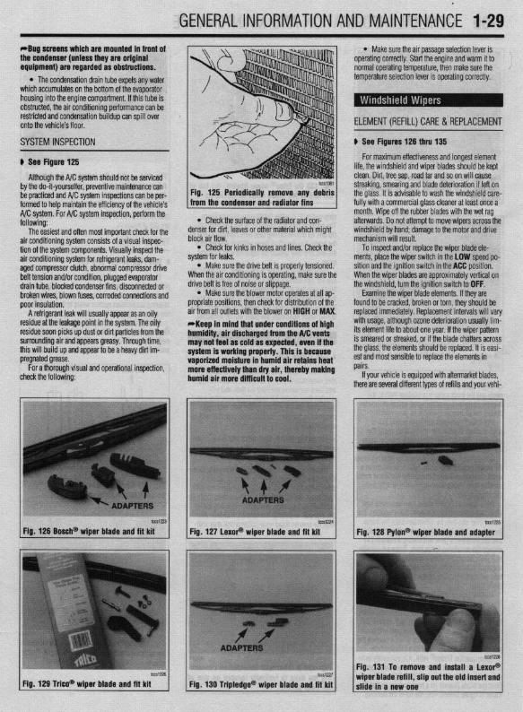
GENERALINFORMATIONAND MAlNTENANdE 1-29 i
*Bug screens which are mounted in front of the condenser (unless they are original equipment) are regarded as obstructtons.
l The condensation drain tube expels any water which accumulates on the bottom of the evaporator housing into the engine compartment. If this tube is obstructed, the air conditioning performance can be restricted and condensation buildup can spill over onto the vehicle’s floor.
l Make sure the air passage selection lever is operating correctly. Start the engine and warm it to normal operating temperature, then make sure the temperature selection lever is operating correctly.
-w ~1 ELEMENT(REFILL)CARE& REPLACEMENT
SYSTEM INSPECTION
b See Figure 125
b See Figures 126 thru 135
For maximum effectiveness and longest element
Although the A/C system should not be serviced by the do-it-yourselfer, preventive maintenance can be practiced and A/C system inspections can be per- formed to help maintain the efficiency of the vehicle’s A/C system. For A/C system inspection, perform the following:
The easiest and often most important check for the air conditioning system consists of a visual inspec- tion of the system components. Visually inspect the air conditioning system for refrigerant leaks, dam- aged compressor clutch, abnormal compressor drive belt tension and/or condition, plugged evaporator drain tube, blocked condenser fins, disconnected or broken wires, blown fuses, corroded connections and poor insulation.
A refrigerant leak will usually appear as an oily residue at the leakage point in the system. The oily residue soon picks up dust or dirt particles from the surrounding air and appears greasy. Through time, this will build up and appear to be a heavy dirt im- pregnated grease.
For a thorough visual and operational inspection, check the following:
* Check the surface of the radiator and con- denser for dirt, leaves or other material which might block air flow.
l Check for kinks in hoses and lines. Check the system for leaks.
l Make sure the drive belt is properly tensioned. When the air conditioning is operating, make sure the drive belt is free of noise or slippage.
l Make sure the blower motor operates at all ap- propriate positions, then check for distribution of the air from all outlets with the blower on HIGH or MAX. *Keep in mind that under conditions of high humidity, air discharged from the A/C vents may not feel as cold as expected, even if the system is working properly. This is because vaporized moisture in humid air retains heat more effectively than dry air, thereby making humid air more difficult to cool.
lifp thp winrkhi&i nnri winor hlarlP~ shmM hP kmt . . . “ . . I . ” . . * “ “ I . . “ . ” I . . ” . . . r ” * “ . “ “ “ ” “ , , “ “ , ” “ ” ,~“r~
clean. Dirt, tree sap, road tar and so on will cause streaking, smearing and blade deterioration if left on the glass. It is advisable to wash the windshield care- fully with a commercial glass cleaner at least once a month. Wipe off the rubber blades with the wet rag afterwards. Do not attempt to move wipers across the windshield by hand; damage to the motor and drive mechanism will result.
To inspect and/or replace the wiper blade ele- ments, place the wiper switch in the LOW speed po- sition and the ignition switch in the ACC position. When the wiper blades are approximately vertical on the windshield, turn the ignition switch to OFF.
Examine the wiper blade elements. If they are found to be cracked, broken or torn, they should be replaced immediately. Replacement intervals will vary with usage, although ozone deterioration usually lim- its element life to about one year. If the wiper pattern is smeared or streaked, or if the blade chatters across the glass, the elements should be replaced. It is easi- est and most sensible to replace the elements in pairs.
If your vehicle is equipped with aftermarket blades, there are several different types of refills and your vehi-
tcca-23
Fig. 126 Bosch@ wiper blade and fft kit
Fig. 129 T&o* wioer blade and fit kit
tCS1224 lW1Z?5
Fig. 127 LexoP wiper blade and fit kit Fig. 128 Pylon@ wiper blade and adapter
Fig. 131 To remove and install a LexoP
Fig, 130 Tripledge@ wiper blade and fit kit wiper blade refill, slip out the old insert and slide in a new one
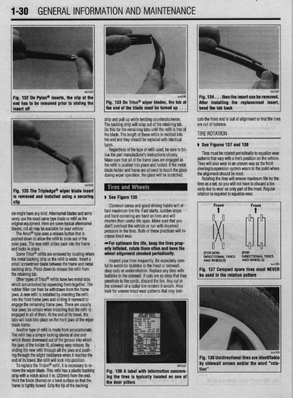
.
l-30 GENERAL'INFORMATIONAND MAINTENANCE
n Pylon@ inserts, the clip be removed prior to siidi
then the insert can be re After installing the replacement
strip and pull up while twisting counterclockwise. The backing strip will snap out of the retaining tab. Do this for the remaining tabs until the refill is free of the blade. The length of these refills is molded into the end and they should be replaced with identical types.
cate the front end is out of alignment or that the tires are out of balance.
TIRE ROTATION
# See Figures 137 and 138
Tires must be rotated periodically to equalize wear patterns that vary with a tire’s position on the vehicle. Tires will also wear in an uneven way as the front
1 Fin 1% Tha Trinlarlna@
cle might have any kind. Aftermarket blades and arms rarely use the exact same type blade or refill as the original equipment. Here are some typiel aftermarket blades; not all may be available for your vehicle:
The Anco@ type uses a release button that is pushed down to allow the refill to slide out of the yoke jaws. The new refill slides back into the frame , and locks in place.
Some Trico@ refills are removed by locating where the metal backing strip or the refill is wider. Insert a small screwdriver blade between the frame and metal backing strip. Press down to release the refill from the retaining tab.
Other types of Trico@’ refills have two metal tabs which are unlocked by squeezing them together. The rubber filler can then be withdrawn from the frame iaws. A new refill is installed bv insertina the refill
lowed to touch the olass steering/suspension system wears to the point where the alianment should be reset.
# See Figure 138
Common sense and good driving habits will af- ford maximum tire life. Fast starts, sudden stops and hard cornering are hard on tires and will shorten their useful life span. Make sure that you don’t overload the vehicle or run with incorrect pressure in the tires. Both of these practices will in- crease tread wear. *For optimum tire life, keep the fires prop eriy inflated, rotate them often and have the wheel alignment checked periodically.
Inspect your tires frequently. Be especially care- ful to watch for bubbles in the tread or sidewall, deep cuts or underinflation. Replace any tires with bubbles in the sidewall. If cuts are so deep that they penetrate to the cords, discard the tire. Any cut in the sidewall of a radial tire renders it unsafe. Also look for uneven tread wear patterns that may indi-
Rotating the tires will ensure maximum life for the tires as a set, so you will not have to discard a tire early due to wear on only part of the tread. Regular
DIRECTIONAL TIRES DIRECTIONAL TIRES
jnto the front frame jaws and &ding it rearward to engage the remaining frame jaws. There are usually four jaws; be certain when installing that the refill is engaged in all of them. At the end of its travel, the tabs will lock into place on the front jaws of the wiper blade frame.
Another type of refill is made from polycarbonate. The refill has a simple locking device at one end which flexes downward out of the groove into which the jaws of the holder fit, allowing easy release. By sliding the new refill through all the jaws and push- ing through the slight resistance when it reaches the end of its travel, the refill will lock into position.
To replace the Tridon@ refill, it is necessary to re- move the wiper blade. This refill has a plastic backing strip with a notch about 1 in. (25mm) from the end. Hold the blade (frame) on a hard surface so that the frame is tightly bowed. Grip the tip of the backing
Fig. 138 A label with information concern- ing the tires is typically located on one of the door pillars
tion”
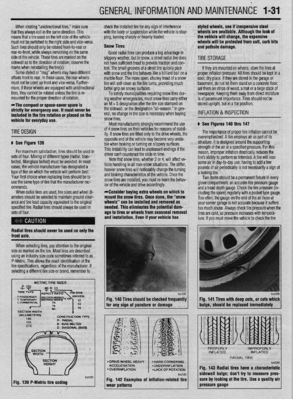
GENERALINFORMATIONAND MAlNTENANdE 1-31 When rotating “unidirectional tires,” make sure
that they always roll in the same direction. This means that a tire used on the left side of the vehicle must not be switched to the right side and vice-versa. Such tires should only be rotated front-to-rear or rear-to-front, while always remaining on the same side of the vehicle. These tires are marked on the sidewall as to the direction of rotation; observe the marks when reinstalling the tire(s).
Some styled or “mag” wheels may have different offsets front to rear. In these cases, the rear wheels must not be used up front and vice-versa. Further- more, if these wheels are equipped with unidirectional tires, they cannot be rotated unless the tire is re- mounted for the proper direction of rotation. *The compact or space-saver spare is strictly for emergency use. it must never be included in the tire rotation or placed on the vehicle for everyday use.
check the installed tire for any sign of interference with the body or suspension while the vehicle is stop- ping, turning sharply or heavily loaded.
Snow Tires Good radial tires can produce a big advantage in
slippery weather, but in snow, a street radial tire does not have sufficient tread to provide traction and con- trol. The small grooves of a street tire quickly pack with snow and the tire behaves like a billiard ball on a marble floor, The more open, chunky tread of a snow tire will self-clean as the tire turns, providing much better grip on snowy surfaces.
To satisfy municipalities requiring snow tires dur- ing weather emergencies, most snow tires carry either an M + S designation after the tire size stamped on the sidewall, or the designation “all-season.” In gen- eral, no change in tire size is necessary when buying snow tires.
Most manufacturers stronqlv recommend the use
styled wheels, see if inexpensive steel wheels are available, Although the look of the vehicle will change, the expensive wheels will be protected from salt, curb hits and pothole damage.
TIRESTORAGE
If they are mounted on wheels, store the tires at proper inflation pressure. All tires should be kept in a cool, dry place. If they are stored in the garage or basement, do not let them stand on a concrete floor; set them on strips of wood, a mat or a large stack of newspaper. Keeping them away from direct moisture is of paramount importance. Tires should not be stored upright, but in a flat position.
INFLATION & INSPECTION
b See Figures 140 thru 147
TIRE DESIGN
p See Figure 139
for maximum satisfaction, tires should be used in sets of four. Mixing of different types (radial, bias- belted, fiberglass belted) must be avoided. In most cases, the vehicle manufacturer has designated a type of tire on which the vehicle will perform best. Your first choice when replacing tires should be to use the same type of tire that the manufacturer rec- ommends.
When radial tires are used, tire sizes and wheel di- ameters should be selected to maintain ground clear- ante and tire load caoacitv eauivalent to the oriainal specified tire. Radial tiresshould always be used in sets of four.
of 4 snow tires on their \ lehicies for reasons of stabil- ity. If snow tires are fitter 1 only to the drive wheels, the opposite end of the vehil cle may become very unsta- ble when braking or turn ring on slippery surfaces. This instability can lead to unpleasant endings if the A*:,,“- r-..l, ̂ _.. ..& ^_^^, &I. UIIVU MII I LUUII~~MLL iue slide in time.
Note that snow tires, whether 2 or 4, will affect ve- hicle handling in all non-snow situations. The stiffer, heavier snow tires will noticeably change the turning and braking characteristics of the vehicle. Once the snow tires are installed, you must re-learn the behav- ior of the vehicle and drive accordingly. *Consider buying extra wheels on which to mount the snow tires. Once done, the “snow iheeis” can be installed and removed as needed. This eliminates the potential dam- age to tires or wheels from seasonal removal and installation. Even if your vehicle has
lb
The importance of proper tire inflation cannot be overemphasized. A tire employs air as part of its structure. It is designed around the supporting strength of the air at a specified pressure. For this reason, improper inflation drastically reduces the tire’s ability to perform as intended. A tire will lose some air in day-to-day use; having to add a few pounds of air periodically is not necessarily a sign of a leaking tire.
Two items should be a permanent fixture in every glove compartment: an accurate tire pressure gauge and a tread depth gauge. Check the tire pressure (in- eluding the spare) regularly with a pocket type gauge. Too often, the gauge on the end of the air hose at vnr rr corner narane is not accurate because it suffers
~rs check tire oressure when the
Radial tires should never be used on only the
XI I._. ‘-’ --“‘“’ J s too much abuse. Alwa! tires are cold, as pressure increases with tempera- ture. If you must move the vehicle to check the tire
front axle.
When selecting tires, pay attention to the original size as marked on the tire. Most tires are described using an industry size code sometimes referred to as P-Metric. This allows the exact identification of the tire specifications, regardless of the manufacturer. If selecting a different tire size or brand, remember to
METRIC TIRE SIZES
(MILLIMETERS) 145
CDNStRUCtlDN l-6-E R - RADIAL
D WA9
Fig. 139 P-Metric tire coding
Fig. 140 Tires should be checked frequently I I
Fig. 141 Tires with deep cuts, or cuts which for any sion of auncture or damaoe buioe, should be replaced immediately
l DRIVE WHEEL HEAW ACCELERATION
l OVERINFLATION *LACK OF ROTATION
Fig. 142 Examples of inflation-related tire
RADIAL TIRE
fig. 143 Radial tires have a characteristic sidewall bulge; don’t try to measure pres- sure by looking at the tire. Use a quality air pressure gauge
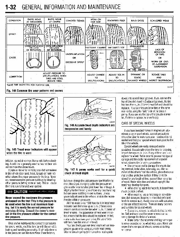
.
1-32 GENERALINFORMATIONAND MAINTENANCE
CONDITION
EFFECT
CAUSE
CORRECTION
UNDER-INFLATION
EXCESSIVE SPEED’ WORN OR OUT- OF-ALIGNMENT
ADJUST PRESSURE TO SPECIFICATIONS WHEN
TIRES ARE COOL ROTATE TIRES
/ BALANCE WHEELS INSPECT SUSPENSION
HAVE TIRE INSPECTED FOR FURTHER USE. lCCSi267
ig. 144 Common tire wear patterns and causes
1~~~1265
Fig. 145 Tread wear indicators will appear when the tire is worn
inflation, do not drive more than a mile before check- ing. A cold tire is generally one that has not been dri- ven for more than three hours.
A plate or sticker is normally provided somewhere in the vehicle (door post, hood, tailgate or trunk lid) which shows the proper pressure for the tires. Never counteract excessive pressure build-up by bleeding off air pressure (letting some air out). This will cause the tire to run hotter and wear quicker.
Never exceed the maximum tire pressure embossed on the tire! This is the pressure to be used when the tire is at maximum load- ing, but it is rarely the correct pressure for everyday driving. Consult the owner’s man- ual or the tire pressure sticker for the correct tire pressure.
Once you’ve maintained the correct tire pressures for several weeks, you’ll be familiar with the vehicle’s braking and handling personality. Slight adjustments in tire pressures can fine-tune these characteristics,
1~~~1264
Fig. 146 Accurate tread depth indicators are inexuensive and handv
Fig. 147 A penny works well for a quick check of tread death
but never change the cold pressure specification by more than 2 psi. A slightly softer tire pressure will give a softer ride but also yield lower fuel mileage. A slightly harder tire will give crisper dry road handling but can cause skidding on wet surfaces. Unless you’re fully attuned to the vehicle, stick to the recom- mended inflation pressures.
All tires made since 1968 have built-in tread wear indicator bars that show up as j/2 in. (13mm) wide smooth bands across the bre when V,~ in. (1.5mm) of tread remains. The appearance of tread wear indica- tors means that the tires should be replaced. In fact, many states have laws prohibiting the use of tires with less than this amount of tread.
You can check your own tread depth with an inex- pensive gauge or by using a Lincoln head penny. Shp the Lrncoln penny (with Lincoln’s head upside-
down) into several tread grooves. If you can see the top of Lincoln’s head in 2 adjacent grooves, the tire has less than V,~ in. (1.5mm) tread left and should be replaced. You can measure snow tires in the same manner by using the “tails” side of the Lincoln penny. If you can see the top of the Lincoln memor- ial, its time to replace the snow tire(s).
CAREOFSPECIALWHEELS
If you have invested money in magnesium, alu- minum alloy or sport wheels, special precautions should be taken to make sure your investment is not wasted and that your special wheels look good for the life of the vehicle.
Special wheels are easily damaged and/or scratched. Occasionally check the rims for cracking, impact damage or air leaks. If any of these are found, replace the wheel. But in order to prevent this type of damage and the costly replacement of a special wheel, observe the following precautions:
l Use extra care not to damage the wheels dur- ing removal, installation, balancing, etc. After re- moval of the wheels from the vehicle, place them on a mat or other protective surface. If they are to be stored for any length of time, support them on strips of wood. Never store tires and wheels upright; the tread may develop flat spots.
l When driving, watch for hazards; it doesn’t take much to crack a wheel.
l When washing, use a mild soap or non-abra- sive dish detergent (keeping in mind that detergent tends to remove wax). Avoid cleansers with abrasives or the use of hard brushes. There are many cleaners and polishes for special wheels.
l If possrble, remove the wheels during the win- ter. Salt and sand used for snow removal can se- verely damage the finish of a wheel.
l Make certain the recommended lug nut torque is never exceeded or the wheel may crack. Never use snow chains on special wheels; severe scratching will occur.

GENERALINFORMATIONAND MAINTENANC-E 1133
Used fluids such as engine oil, transaxle fluid, an- tifreeze and brake fluid are hazardous wastes and must be disposed of properly. Before draining any fluids, consult with your local authorities; in many ar- eas, waste oil, antifreeze, etc. is being accepted as a part of recycling programs. A number of service sta- tions and auto parts stores are also accepting waste fluids for recycling.
Be sure of the recycling center’s policies before draining any fluids, as many will not accept different fluids that have been mixed together.
ENGINE OIL
6 See Figure 148 WMitsubishi recommends that SAE 5W-30 viscosity engine oil should be used for all clia mate conditions, however, SAE low-30 is ac ceptable for vehicles operated in moderate- to-hot climates.
the SAE number, the lighter the oil; the lower the vis- cosity, the easier it is to crank the engine in cold weather but the less the oil will lubricate and protect the engine in high temperatures. This number is marked on every oil container.
Oil viscosity’s should be chosen from those oils recommended for the lowest anticipated temperatures during the oil change interval. Due to the need for an oil that embodies both good lubrication at high tem- peratures and easy cranking in cold weather, multi- grade oils have been developed. Basically, a multi- grade oil is thinner at low temperatures and thicker at high temperatures. For example, a low-40 oil (the W stands for winter) exhibits the characteristics of a 10 weight (SAE 10) oil when the car is first started and the oil is cold. Its lighter weight allows it to travel to the lubricating surfaces quicker and offer less resis- tance to starter motor cranking than, say, a straight 30 weight (SAE 30) oil. But atier the ensine reaches operating temperature, the low-40 oil begins acting like straight 40 weight (SAE 40) oil, its heavier weight providing greater lubrication with less chance of foaming than a straight 30 weight oil.
Synthetic oil is not for every car and every type of driving, so you should consider your engine’s condi- tion and your type of driving. Also, check your car’s warranty conditions regarding the use of synthetic oils.
FUEL
All models equipped with a SOHC (Single Over- head Camshaft) engine are designed to operate using regular unleaded fuel with a minimum of 87 octane. All models equipped with a DOHC (Dual Overhead Camshaft) engine are designed to operate using reg- ular unleaded fuel with a minimum of 91 octane. Mit- subishi warns that using gasoline with a lower octane rating can cause persistent and heavy knocking, and may cause internal engine damage.
If your vehicle is having problems with rough idle or hesitation when the enoine is cold, it mav be caused by low volatility fuel. If this occurs, iry a dif- ferent grade or brand of fuel.
'OPERATION 1~ FOREIGN COUNTRIES
lccS1235
Fig. 148 look for the API oil identification Non-detergent motor oils or straight mineral label when choosing your enaine oil oils should not be used in your engine.
When adding oil to the crankcase or changing the 0 Nil or filter, it is important that oil of an equal quality I original equipment be used in your car. The use of . tc
mtenor 011s may void the warranty, damage your en- gine, or both.
__ The SAE (Society of Automotive Engineers) grade
number of oil indicates the viscosity of the oil (its ability to lubricate at a given temperature). The lower
Fig. 149 Grasp the oil level dipstick and pull upward to remove it from the dipstick tube
The API (American Petroleum Institute) designa- tions, also found on the oil container, indicates the classification of engine oil used under certain given operating conditions. Only oils designated for use Service SJ heavy duty detergent should be used in your car. Oils of the SJ type perform may functions
If you plan to drive your car outside the United States or Canada, there is a possibility that fuels will be too low in anti-knock quality and could produce engine damage. It is wise to consult with local au- thorities upon arrival in a foreign country to deter- mine the best fuels available.
inside the engine besides their basic lubrication. Through a balanced system of metallic detergents and polymeric dispersants, the oil prevents high and low temperature deposits and also keeps sludge and dirt particles in suspension. Acids, particularly sulfu- OILLEVELCHECK ric acid, as well as other by-products of engine com- bustion are neutralized by the oil. If these acids are # See Figures 149, 150, and 151 allowed to concentrate, thev can cause corrosion and
\
rapid wear of the internal engine parts.
Synthetic Oil There are many excellent synthetic and fuel-effi-
cient oils currently available that can provide better gas mileage, longer service life and, in some cases, better engine protection. These benefits do not come without a few hitches, however; the main one being the price of synthetic oil, which is significantly more expensive than conventional oil.
.
The EPA warns that urolonoed contact with used engine oil ma; cause-a number of skin disorders, including cancer! You should make every effort to minimize your exposure to used engine oil. Protective gloves should be worn when changing the oil. Wash your hands and any other exposed skin areas as soon as possible after exposure to used en- gine oil. Soap and water, or waterless hand cleaner should be used.
Fig. 150 Wipe the dipstick clean and rein- sert it into the dipstick tube to get the cor- rect oil level
The engine oil dipstick is typically located in the
Fig. 151 The oil level should be between the marks/notches on the dipstick
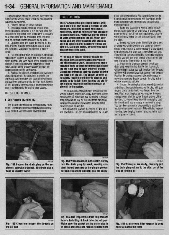
.
l-34 GENERALINFORMATIONAND MAINTENANCE Engine oil level should be checked every time you
put fuel in the vehicle or are under the hood perform- miles of highway driving. Fluid which is warmed to normal operating temperature will flow faster, drain
ing other maintenance. 1. Park the vehicle on a level surface. 2. The enaine mav be either hot or cold when
, if it is hot, wait a few min- checking oil level.
The EPA warns that prolonged contact with used engine oil may cause a num’ * * * dianrAnrr inrldinn ranrnrl V#lll
more completely and remove more contaminants frnm tho clnnine
utes after the engine has been turned OFF to allow the oil to drain back into the crankcase. If the engine is cold, do not start it before checking the oil level.
point on the oil pan. If not, you may have to raise the vehicle slightly higher on one jackstand (side) than
3. Open the hood and locate the engine oil dip- stick. Pull the dipstick from its tube, wipe it clean, and reinsert it. Make sure the diDstick is fullv in- serted.
4. Pull the dipstick from its tube again. Holding it
to used engin be worn whet handsandan so*m ..#a . . . . .
IDer 01 SKlll u,yu,u=,+, ,,,u,uu,,,u uu,,u=, i , vu should
uff art to minimize your exposure le oil. Protective gloves should 1 changing the oil. Wash your y other exposed skin areas as
111 aJ vv4ble after exposure to used en- m nil St-mn mwl w&or nr umtarlncr hand gin Y “II. ““up “ll” .,U.“I, “rn W.Y.“. .““I .I....”
cleaner should be used.
horizontally, read the oil level. The oilshould be be- tween the MIN and MAX marks or the notches on the dipstick. If the oil is below the MIN mark or lower notch, add oil of the proper viscosity through the capped opening of the valve cover.
*The engine oil and oil filter should be changed at the recommended intervals on the Maintenance Chart. Though some manu- facturers have at times recommended chang- ing the filter only at every other oil change, ’ Chilton recommends that you always change
ll”,,, Cl>” ““y”‘“. 1. Raise and support the vehicle safely on jack-
stands. Make sure the oil drain olua is at the lowest
the other. 2. Before you crawl under the vehicle, take a look
at where you will be working and gather all the nec- essary tools, such as a few wrenches or a ratchet and strip of sockets, the drain pan, some clean rags and, if the oil filter is more accessible from underneath the vehicle, you will also want to grab a bottle of oil, the new filter and a filter wrench at this time.
5. Reolace the diostick. and check the level aaain . The benefit of fresh oil
p See Figures 152 thru 153
The oil and filter should be changed every 7,500 miles (12,000 km) under normal service and every 3,000 miles (5,000 km) under severe service.
93151p-55
Fig. 152 loosen the drain plug on the en- a wrench. The drain plug’s
3. Position the drain pan beneath the oil pan drain plug. Keep in mind that the fast flowing oil, which will spill out as you pull the plug from the pan, will flow with enough force that it could miss the pan. Position the drain pan accordingly and be ready to move the pan more directly beneath the plug as the oil flow lessens to a trickle.
4. Loosen the drain ~lua with a wrench (or socket and driver), then carefuliy unscrew the plug with your fingers. Use a rag to shield your fingers from the heat. Push in on the plug as you unscrew it so you
draining the oil, make sure that the engine is at oper- can feel when all of the screw threads are out of the ating temperature. Hot oil will hold more impurities hole (and so you will keep the oil from seeping past in suspension and will flow better, allowing the re- the threads until you are ready to remove the plug). moval of more oil and dirt. You can then remove the plug quickly to avoid hav-
It is a good idea to warm the engine oil first so it ing hot oil run down your arm. This will also help as- will flow better. This can be accomolished bv 15-20 sure that have the plug in your hand, not in the bot-
tom of a pan of hot oil.
Fig. 153 When loosened sufficiently, slowly turn the drain plug by hand, keeping con- Fig. 154 When you are ready, carefully pull
Fig. 156 Also inspect the drain plug th before installing it back into the oil
Fig. 155 Clean and inspect the threads on the oil pan
Make sure the gasket on the drain plug is in place and does not require replacement
Fig. 157 A plier-type filter wrench Is used here to loosen the filter
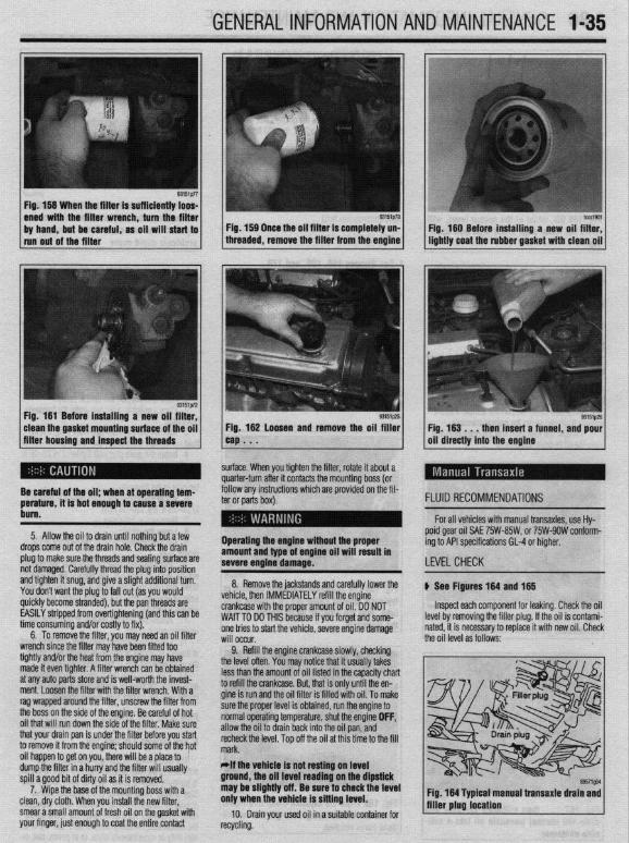
GENERALINFORMATIONAND MAINTENANCE l-35
Fig. 158 When the filter is sufficiently loos-
Fig. 181 Before installing a new oil filter, clean the gasket mounting surface of the oil filter housing and inspect the threads
Fig. 182 Loosen and remove the oil filler cap . . .
surface. When you tighten the filter, rotate it about a quarter-turn after it contacts the mounting boss (or
Fig. 183 . , , then insert a funnel, and pour oil directly into the engine
follow any instructions which are provided on the fil- ter or parts box).
Operating the engine without the proper amount and type of engine oil will result In severe engtne damage.
FLUID RECOMMENDATIONS
For all vehicles with manual transaxles, use Hy- poid gear oil SAE 75W-85W, or 75W-9OW conform- ing to API specifications GL-4 or higher.
LEVELCHECK
Be careful of the oil; when at operating tem- perature, it is hot enough to cause a severe bum.
5. Allow the oil to drain until nothing but a few drops come out of the drain hole. Check the drain plug to make sure the threads and sealing surface are not damaged. Carefully thread the plug into position and tighten it snug, and give a slight additional turn. You don’t want the plug to fall out (as you would quickly become stranded), but the pan threads are EASILY stripped from overtightening (and this can be time consuming and/or costly to fix).
6. To remove the filter, you may need an oil filter wrench since the filter may have been fitted too tightly and/or the heat from the engine may have made it even tighter. A filter wrench can be obtained at any auto parts store and is well-worth the invest- ment. Loosen the filter with the filter wrench. With a rag wrapped around the filter, unscrew the filter from the boss on the side of the engine. Be careful of hot oil that will run down the side of the filter. Make sure that your drain pan is under the filter before you start to remove it from the engine; should some of the hot oil happen to get on you, there will be a place to dump the filter in a hurry and the filter will usually spill a good bit of dirty oil as it is removed.
7. Wipe the base of the mounting boss with a clean, dry cloth. When you install the new filter, smear a small amount of fresh oil on the gasket with your finger, just enough to coat the entire contact
8. Remove the jackstands and carefully lower the vehicle, then IMMEDIATELY refill the engine crankcase with the proper amount of oil. DO NOT WAIT TO DO THIS because if you forget and some- one tries to start the vehicle, severe engine damage will occur.
9. Refill the engine crankcase slowly, checking the level oflen, you may r..‘:-- U.-1 :L ..-..” II.. .-L-e lVL,VY II,UL II UUUU,,J ,“,\U.J less than the amount of oil listed in the capacity chart to refill the crankcase. But, that is only until the en- gine is run and the oil filter is filled with oil. To make sure the proper level is obtained, run the engine to normal operating temperature, shut the engine OFF, allow the oil to drain back into the oil pan, and recheck the level. Top off the oil at this time to the fill mark. *If the vehicle Is not resting on level ground, the oil level reading on the dipstick may be slightly off. Be sure to check the level only when the vehicle is sitting level.
10. Drain your used oil in a suitable container for recycling.
b See Flgures 184 and 185
Inspect each component for leaking. Check the oil level by removing the filler plug. If the oil is contami- nated, it is necessary to replace it with new oil. Check the oil level as follows:
89571gM
Fig. 164 Typtcal manual transaxle drain and filler plug location

.
l-36 GENERALINFORMATIONAND MAINTENANCE Install the drain plug and tighten to 22 ft. Ibs.
(304Nm) 5. Refill the transaxle to the proper level, as
shown in the Capacities chart, with the appropriate fluid. The oil level should be at the bottom of the oil filler hole.
I
6. When the oil reaches the orooer level, install the filler plug and tighten to 22 ft. Ibs. (30 Nm).
FLUID RECOMMENDATIONS
8957i565
Fig, 165 Oil, when at the proper level, will reach the lower edge of tC=+ frfr*r u*rn -non- ing
Mitsubishi recommends the use of Mercon@auto- matic transmission fluid.
LEVELCHECK
Fig. 170 The fluid level is OK if it is within the between the HOT and ADD areas on the &&i& Do not overfill the transaxle or -.*".."... -- .*"- problems could o ccur
1. Makesure the vehicle is oarked on a level sur- face.
2. Remove the filler plug and make sure the oil level is up to the lower edge of the filler plug hole.
3. Check to be sure that the transaxle oil is not noticeably dirty and that it has a suitable viscosity.
u See Figures 168,169, and 170
fluid is at normal operating temperature, drive the ve-
The transaxle dipstick is located behind the air in-
hicle at least 10 miles.
let hose, towards the firewall. 1. Park the vehicle on a level surface. 2. The transaxle should be at normal operating
temperature when checking fluid level. To ensure the
5. Pull the dipstick from its tube again. Holding it horizontally, road the fluid level. The fkrid should be between the MIN and MAX mark. If the fluid is below the MIN mark, add fluid through the dipstick tube.
DRAIN & REFILL
6. Insert the dipstick, and check the level again after adding any fluid. Be careful not to overfill the transaxle.
3. With the selector lever in P and the parking DRAIN & REFILL u See Figures 166 and 167
1. Make sure the vehicle is parked on a level sur- face.
2. Raise and safely support the vehicle. Place a
brake applied, start the engine. 4. Open the hood and locate the transaxle fluid
dipstick. Pull the dipstick from its tube, wipe it clean, and reinsert it. Make sure the dipstick is fully in- serted.
suitable drain pan under the manual transaxle. 3. Remove the filler plug and the drain plug and
allow the oil to drain completely.
Fig. 166 The automatic transaxle dipstick is typically located under the air cleaner inlet
Fig. 166 Use a box-end wrench to loosen the manual transaxle drain plug . . .
tube. Pull the dipstick up to remove it from the transaxle
Fig. 169 Wipe the dipstick clean and Insert
/fluid level reading ., it mto the transaxle agam to get the correct
j
The fluid should be changed according to the schedule in the Maintenance Intervals chart. If the car is normally used in severe service, such as stop and start driving, trailer towing, or the like, the interval should be halved. If the car is driven under especially nasty conditions, such as in heavy city traffic where the temperature normally reaches 90°F (32%), or in very hilly or mountainous areas, or in police, taxi, or
b See Figures 171 thru 177
1. Raise and support the vehicle safely. 2. Place a suitable drain pan under the transaxle
drain plug. 3. Remove the transaxle pan drain plug. Let the
fluid completely drain out of the transaxle. 4. Install the drain plug and tighten it to 22-25 ft.
lbs. (30-35 Nm). 5. If equipped, remove the drain plug on the dif-
ferential of the transaxle. 6. Install the differential drain plug and tighten ft
to 22-25 ft. Ibs. (30-35 Nm). 7. Remove the drain pan. 8. Lower the vehicle. 9. Fill the transaxle through the dipstick to the
proper level. 10. Place the gear selector lever in P and start the
engine. Run the engine at idle, engage the emergency brake and hold the brake pedal down. Move the gear selector lever through all transaxle ranges for approx- imately 5 minutes.
11. Return the selector lever to P and leave the engine running at idle.
12. Check the transaxle fluid level. The fluid level at normal operating temperature should read within the crosshatched area of the fluid level dipstick.
13. If the fluid level reads below the crosshatched area, adjust the level by adding fluid in small incre- ments until the correct fluid level is obtained.
PAN &FILTER SERVICE
b See Figures 178 thru 184

_. . I . . - . - . _ .
GENERALINFORMATIONAND MAINTENANCE l-37
Fig. 172 Carefully pull the transaxie drain plug out and to the side, out of the way oi flowing transaxie oil
Fig. 173 The differential drain plug is lo- cated at the bottom of the transaxie, to the left of the fluid pan. Typically the drain plug reauires a 17mm wrench
periodically checking the fluid level to make sure you do not overfill the transaxle
pan mounting bolts, a 1Omm wrench is re- Fig. 179 . . , then carefully lower the fluid quired. Remove the pan retaining bolts . . . pan from the transaxle
Fig, 181 . , . then remove the transaxie film ter from the valve body
Fig. 182 Remove the transaxie pan gasket from the pan

t
1-38 GENERALINFORMATIONAND MAINTENANCE 11 I Add the recommended automatic transaxle
fluid to the transaxle through the dipstick tube. You will need a long necked funnel, or a funnel and tube to do this. A quick check of the capacities chart later in this Section will reveal the capacity of the transaxle in your vehicle. On a first fill after removing the pan and filter, this number should be cut into a ‘hand checked on the dipstick before refilling.
12. With the transaxle in P, put on the parking brake, block the front wheels, start the engine and let it idle. DO NOT RACE THE ENGINE. DO NOT MOVE THE LEVER THROUGH ITS RANGES.
13. With the lever in Park, check the fluid level. If it’s OK, take the car out for a short drive, park on a level surface, and check the level again, as outlined earlier in this section. Add more fluid if necessary. Be careful not to overfill, which will cause foaming and
w fluid loss.
n of the transfer case filler
3. Remove the filler and the drain plug and allow the oil to drain into the drain pan.
4. After the fluid has drained completely, install the drain plug and tighten to 24 ft. Ibs. (32 Nm).
5. Refill the transfer case to the proper level with
Fig. 184 . . . the transaxle case before in- stalling the gasket and pan onto the case
FLUID RECOMMENDATIONS Hypoid gear oil SAE 75W-85W/75W-9OW conform- ing to API specifications GL-4 or higher. The oil level -‘-,*I’ -nnnh +‘* “%om edge of the oil filler hole.
nxfer raw filler nlm and tinhtm When adding fluid or refilling the transfer case, use Hypoid gear oil SAE 75W-85W or 75W-9OW conforming to API specifications 61-4 or higher.
LEVELCHECK
6. Install the tra .._._. ____ .._. T.-J _.._ .lJ . .._.. to 24 ft. lbs. (32 Nm).
7. Carefully lower the vehicle.
u See Figure 185
, 1 FLUID RECOMMENDATIONS
delivery service, the fluid should be changed accord- ing to the severe service schedule.
The fluid must be hot before it is drained; a 20 u See Figure 187
Since fluid viscosity range may vary depending on specific temperature range of operation, please refer
~~
tne transaxle case. You’ll be very sorry later if you do. bottom edge of the transfer case filler 1 1 Fig. 187 Rear axle lubricant application I *If the drained fluld is discolored (brown or 1 plug hole chart black), thick, or pmmll~ hmmt nnrinmm I
transaxle trouble .llln3llU ““III., url,““P
s, probably due to overheat- ,r..rr,rA “#.a.- rrdr trig, should be susp~~lr;u. lvUl vLlr J
transaxle should be inspected by a reliable transaxle specialist to determine the prob- lem.
5. Remove the pan and gasket. 6. Clean the pan with solvent and allow it to air
dry. If you use a rag to wipe out the pan, you risk leaving bits of lint behind, which will clog the dinky hydraulic passages in the bansaxle.
7. Remove the filter retaining bolts and remove the filter from the valve bodv.
lnsoect each component for leaking. Check the oil he filler plug. If the oil is contami- ry to replace it with new oil. if% nn IPVPI z11rf2r~
level by removing t nated, it is necessa
1. Park the vehi,., -.. ,-.“, __. ,“-_. 2. Remove the filler plug and make sure the oil
level reaches the lower edge of the filler plug hole. 3. Check to be sure that the oil is not noticeably
dirty and that it has the proper viscosity. 4. If necessary, add oil through the filler hole until
is runs out of the hole.
to the accompanying chart for the proper fluid for your vehicle.
LEVEL CHECK
1. Make sure the vehicle is parked on level ground.
2. Remove the oil fill plug to check the oil level. 3. The oil level is sufficient if it reaches the lower
portion of the filler plug hole. If the fluid is low, add as required through the filler plug.
To install: . 8. Install a new filter, then install the retaining
bolts and tighten them to 5 ft. Ibs. (7 Nm). 9. Position the gasket on the pan, then install
the pan. Tighten the bolts evenly and in rotation to 8-9ft. Ibs. (10-12 Nm.). Do not overtighten.
IO. Lower the vehicle.
DRAIN & REFILL
I8 DRAIN & REFILL
u See Figure 188 ) See Figure- 14
1. Raise and safely support the vehicle, for access to the transfer case.
2. Place a suitable drain pan under the transfer case fluid drain plug.
1. Position the vehicle on a flat surface or raise and safely support the vehicle in a level position.
2. Place a suitable drain pan under the rear axle.

GENERALINFORMATIONAND MAINTENANCE 1-39 leak. In most cases, you will be able to trace the leak to a loose fitting or damaged hose.
Evaporating ethylene glycol antifreeze will have a sweet smell and leave small, white (salt-like) de- oosits, which can be heloful in tracino a leak.
glove box and passenger side floorboard area, and check the carpet for any signs of moisture. The smartest way to go about finding a leak visually is to first inspect any and all joints in the system such as where the radiator hoses connect to the radiator and the engine. Another thing to look for is white crusty stains that are signs of a leak where the coolant has
6. Install the filler plug and tighten to’24 ft. Ibs. (32 Nm).
7. If raised, carefully lower the vehicle.
amount of fluid. The level should ieach thk bottom of me rating on It, lap3 1s a danciara 10 use out some the oil filler hole. A Qss tin,t.as ran +tw,, 4liE cars are higher. Overpressurizing the system can
lose, or worse, in the radiator or your cooling system is con- IIC~KI LUG MU PuaJbly cause an injury or a burn if s of a leak are probable. There the coolant is hot. Overpressurizing is normally con-
WI” U”.VlUl ,.“,,I I” 9” about finding the source of trolled by the radiator cap which has a vent valve in it your leak. which is opened when the system reaches it’s maxi-
The first wav should be a visual insnection. Durina mum pressure rating. To pressure test the system:
7 “1sl I ly”lsJa IJ” Wll” IJU
\ If a the fluid level of stantly low, the chance
cause a rupture in a I: h.n+n. nrrrn nnA . . . . ..I.
FLUID RECOMMENDATIONS the visual inspection, look around the &tire engine - area including the radiator and the heater hoses. The
*The pressure test should be performed with the enaine OFF.
A good quality ethylene glycol based or other alu- minum compatible antifreeze is recommended for use in the vehicles covered by this manual. It is best to add a 50150 mix of antifreeze and distilled water to avoid diluting the coolant in the system.
interior of the car should be inspected behind the
LEVELCHECK
recovery tank and its marking as a guideline. *Never overfill the recovery tank.
A coolant level that consistently drops is usually a sign of a small, hard to detect leak, although in the worst case it could be a sign of an internal engine
“_y “,~-- 1 Fia. 190 A visual insaection for leaks will 1 sometimes find a leak. This photo shows Fig. 191 Remove the recovery tank cap to
/ * ,, / evfdence of a leak at the upper radfator
* / /the system allow the pressure tester to be connected to
hose-to-thermostat housing junction
Fig. 189 The coolant level should be be-
1 coo,ant recovery tank tween the FULL and LOW levels on the “‘~‘_I j Fig. 192 This cooling system requires a Fig. 193 Thread the adapter onto the re-
e’ffi1pg7 / g’051p96 / 1 covety tank threaded adapter for the recovery tank to al- low the pressure tester to be connected

l-40 GENERALINFORMATIONAND MAINTENANCE
aiffiip98
Fig. 194 Pump the cooling system with pres- sure, making sure not to overpressurize the
1 system or damage can occur
1. Remove the radiator or recovery tank cap. 2. Using the proper adapter, insert it onto the
opening and connect the pressure tester, 3. Begin pressurizing the system by pumping the
pressure tester and watching the gauge, when the maximum pressure is reached, stop.
4. Watch the gauge carefully and see if the pres- sure on the gauge drops, if it does, a leak is definitely present.
5. If the pressure stayed somewhat stable, visu- ally inspect the system for leaks, If the pressure dropped, repressurize the system and then visually inspect the system.
,
/ observe the pressure reading “@‘p~ 1 Fig 195 Watch the gauge on the system and
dropped more than 20%, a leak definitely exists, if the oressure droo is less than 20%. the svstem is most likely okay:
, cooling system when hot; serious burns can
Another way coolant is lost is by a internal engine occur from the steam and hot coolant. Also, leak, causing the oil to be contaminated or the when draining engine coolant, keep in mind coolant to be burned in the process of combustion that cats and dogs are attracted to ethylene and sent out the exhaust. To check for oil contamina- glyeol antifreeze and could drink any that is tion, remove the dipstick and check the condition of left in an uncovered container or in puddles the oil in the oil pan. If the oil is murky and has a on the ground. This will prove fatal in suffi- white or beige “milkshake” look to it, the coolant is cient quantities. Always drain coolant into a contaminating the oil through an internal leak and the sealable container. Coolant should be reuser enqine must be torn down to find the leak. If the oil mless it is contaminated or is several years
6. If no signs of a leak are noticed visually, pres- surize the system to the maximum pressure rating of the system and leave the uressure tester connected fl sr about 30 minutes. Return after 30 minutes and V erify the pressure on the gauge, if the pressure
does not verify the situation, removing the spark plugs one at a time and checking the electrodes for a green or white tint can verify an internal coolant leak and identify which cylinder(s) is the culprit and aiding your search for the cause of the leak. If the spark plugs appear okay, another method is to use a gas analyzer or emissions tester, or one of several hand- held tools that most professional shops possess. This tools are used to check the cooling system for the presence of Hydrocarbons (HC’s) in the coolant.
DRAIN & REFILL
p See figures 196 thru 205
Ensure that the engine is completely cool prior to starting this service.
Never open, service or drain the radiator or
Ippears okay, the coolant can be burned and going jut the tailpipe. A quick test for this is a cloud of Nhite smoke appearing from the tailpipe, especially In start-up. On cold days, the white smoke will ap- Iear, this is due to condensation and the outside emperature, not a coolant leak. If the “smoke test”
Fig. 196 The draincock is usually located at Fig. 197 Gently rotate the draincock coun- the bottom of the radiator terclockwise to open the draincock . . .
Fig. 199 Allow the fluid to drain until it stops and tighten the draineock hand tight
93151p27
1. Remove the recovery tank or radiator cap. 2, Raise and support the vehicle. 3. If necessary, remove the splash shield from un
ler the front of the vehicle.
93im76
Fig, 198 . _ . then allow the coolant to drain out of the radiator and cooling system
Fig. 200 Make sure to heed the caution on the radiator cap and NEVER open the cap
1 when the engine is hot ,, Fig. 201 Grasp the radiator cap and rotate it counterclockwise . . .

.
GENERALINFORMATIONAND MAINTENANCE l-41
93151p18
Fig. 202 . , . to remove the cap from the radiator
93151p17
Fig. 205 Be sure the rubber gasket on the radiator cap has a tight seal
e
Fig. 203 Pour the proper *I~ coolant mix- 1 Fig. 204 . . . make sure to fill the coolant recovery tank to the proper level also ture into the radiator . . . .I
4. Allow the engine to cool completely and drain fluid. Any brake fluid that is removed from ie system again.
5. Repeat this processuntil the drained water is lear and free of scale.
6. Flush the recovery tank with water and leave ’ mpty.
the system should be discarded. Also, do not allow any brake fluid to come in contact with a painted surface; it will damage the paint.
When adding fluid to the system, ONLY use fresh DOT 3 brake fluid from a sealed container. DOT 3 brake fluid will absorb moisture when it is exposed to .a . . . , .*a. . . * .*. . .
-
Never open, service or drain the radiator or cooling system when hot; serious bums can occur from the steam and hot coolant. Also, when draining engine coolant, keep In mind that cats and dogs are attracted to ethylene glycol antifreeze and could drink any that is left in an uncovered container or in puddles on the ground. This will prove fatal in suffi-
4. Place a drain pan of suff i ’ 1 . . . ..I .I. 1,~ cient quantities. Always
tne atmospnere, wnrcn wnr rower 1r.s oourng pomr. A container that has been opened once, closed and placed on a shelf will allow enough moisture to enter over time to contaminate the fluid within. If your brake fluid is contaminated with water, you could boil the brake fluid under hard braking conditions and lose all or some braking ability. Don’t take the risk, buy fresh brake fluid whenever you must add to the system.
crenr capacrry unaer me drain) on the radiator.
rrrasuc perwcss easuy bind; Before open- ing a plastic radiator petcock, spray it with some penetrating lubricant.
drain coolant into a
earner.
sealable container. Coolant should be reused unless it is contaminated or is several years old.
The brake master cylinder ~a~~~~r,~~ :A I~nnL.4 n-n
7. Fill and bleed the cooling system as described
Brake fluid contains polyglycol ethers and polyglycols. Avoid contact with the eyes and
,LEVEL CHECK
wash your hands thoroughly after handling brake fluid. If vou do oet brake fluid in vour eyes, flush your eyeswith clean, runniug wa- a-.. ‘Y-- ar -l-..n-- II -.._ I____
k See Figures 206 thru 211
.a-11-- - __-PA._
radiator and open the petcock ( - w&1--x3_ --mm.._..- . . ..-I...
5. Drain the cooling system completely. 6. Close the petcock. 7. Remove the drain pan.
If necessary, install the splash shield under the 8. L.-l venicie. 9. Lower the vehicle. 10. Determine the capacity of the cooling system,
then properly refill the system at the recovery tank and radiator with a 50/50 mixture of fresh coolant and
fKm”“ll 15 IUMLC” “II-
brake booster and fire- der the hood, attached to the wall on the drivers side of the engine compartment.
FLUID RECOMMENDATIONS
rer mr 13 mmures. IT eye irriIauon persim, or if you have taken brake fluid internally, IMMEDIATELY seek medical assistance.
ala in oreerring me sysrem. 12. Start the engine and allow it to idle until the
thermostat opens (the upper radiator hose will be- come hot). The coolant level should go down, this is normal as the system bleeds the air pockets out of the svstem.
IRVf!l ._._. 14. Turn the engine OFF and check for leaks. IMMEDIATELY seek medical assistance.”
Brake fluid contains polyglycol ethers and polyglycols. Avoid contact with the eyes and wash your hands thoroughly after handling brakefluid. If you do get brake fluid in your eyes, flush your eyes with clean, running wa-
or if vou have taken brake fluid internallv. Before removing the master cylinder reservoir cap,
make sure the vehicle is resting on level ground and
Be careful to avoid spilling any brake fluid on painted surfaces, because the paint coat will become discolored or damaged.
Observe the fluid level indicators on the master ._ ._ __ ‘eve1 should be between the MIN
ano ivw unes. 13. Refill the system with coolant to the proper ter for 15 minutes; If eye irritation persists, cylinder; the tluld II ..J ..I” I....
FLUSHING & CLEANINGTHE SYSTEM
1. Drain the cooling system completely as de: scribed earlier.
2. Close the petcock and fill the system with a cooling system flush (clean water may also be used, but is not as efficient).
3. Idle the engine until the upper radiator hose gets hot.
Clean, high quality brake fluid is essential to the safe and proper operation of the brake system. You should always buy the highest quality brake fluid that is available. If the brake fluid becomes contaminated, drain and flush the system, then refill the master cylin- der with new fluid. Never reuse any brake
clean all dirt away from the top of the master cylinder. Unscrew the cap and fill the master cylinder until the level is between the MIN and MAX lines.
If the level of the brake fluid is less than half the volume of the reservoir, it is advised that you check the brake system for leaks. Leaks in a hydraulic brake system most commonly occur at the wheel cylinder and brake line junction points.

1-42 GENERAL~INFORMATION AND MAINTENANCE
Fig. 206 The fluid level should be between llow,be*“retoch~ckiebrake~ . the MAX and MIN hnes if the fhud level IS
93151p31
Fig. 209 If the master cylinder capgasket is swelled like such, it can be a sign of con- tamination. If the gasket is swelled . . .
Fig. 207 Wipe the master cylinder reservoir clean before opening the cap to ensure that no contamination enters the brake fluid
Fig. 210 . . . make sure to push the gasket back to the normal position
93151p29 I
Fig. 208 Unscrew the master cylinder cap and remove it from the reservoir
Fig. 211 Carefully pour approved brake fluid from a fresh, sealed container directly into the reservoir
2. Inspect the fluid in the reservoir, making sure fluid is between the MAX and the MIN marks.
FLUID RECOMMENDATIONS
When adding or changing the fluid in the systems, use a quality brake fluid conforming to DOT 3 speci- fications from an sealed container. Never reuse old brake fluid.
LEVEL CHECK
b See Figures 212, 213, and 214
1. Wipe the clutch master cylinder reservoir cap and the surrounding area clean with a shop towel.
3. If required, remove the clut ch master cylinder reservoir lid. then add fresh fluid I FLUID RECOMMENDATIONS mark on the’reservoir.
to fill to the top full
When adding or changing the power steering fll$,“” Dexron@il ATF (Automatic Transmission
- - . Be careful to avoid sf Billing any brake fluid on LEVELCHECK painted surfaces, bet :ause the paint coat will become discolored or damaged. b See Figures 215, 216, 217, and 218
4. Reinstall the lid onto the clutch master cylin- Like all other general maintenance items, check der. every 3,OOfl miles (4,800 km) or once a month. In-
5. If removed, install the air cleaner assembly. spect the oil level in the reservoir by checking the po-
Fig. 212 The clutch master cylinder has MAX (A) and MIN (B) fill lines on the reser volr
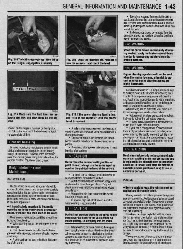
GENERALINFORMATIONAND MAINTENANCE l-43 l Special car washing detergent is the best to
use. Liquid dishwashing detergent can remove wax and leave the car’s paint unprotected and in addition some liquid detergents contains abrasives which can scratch the paint.
l Bird droppings should be removed from the paintwork as soon as possible, otherwise the finish may be permanently stained.
When the car is driven immediately after be- ing washed, apply the brakes several times
93151p14 93151p12
Fig. 215 Twist the reservoir cap, then lift up I I
in order to remove any moisture from the Fig. 216 Wipe the dipstick off, reinsert it braking surfaces.
on the integral cap/dipstick assembly into the reservoir and check the level I
Engine cleaning agents should not be used when the engine is warm, a fire risk is pre- sent as most engine cleaning agents are highly flammable.
sition of the fluid against the mark on the dipstick, Add fluid to the reservoir if the fluid does not reach the appropriate full line.
On most models, the manufacturer doesn’t install lubrication fittings on lube points on the steering linkage or suspension. However, if the lubrication point does have a grease fitting, lubricate with multi- purpose NLGI No. 2 (Lithium base) grease.
CAR WASHING
The car should be washed at regular intervals to remove dirt, dust, insects, and tar and other possibly damaging stains that can adhere to the paint and may cause damage. Proper exterior maintenance also helps in the resale value of the vehicle by maintaining its like-new appearance. Mt is particularly important ta frequentiy wash the car in the wintertime to prevent cor- rosion, when salt has been used on the roads.
There are many precautions and tips on washing, including the following:
l When washing the car, do not expose it do di- rect sunlight.
. Use lukewarm water to soften the dirt before you wash with a sponge, and plenty of water, to avoid scratching.
l A detergent can be used to facilitate the soften- ing of dirt and oil.
* A water-soluble grease solvent may be used in cases of sticky dirt. However, use a washplace with a drainage separator.
l Dry the car with a clean chamois and remem- ber to clean the drain holes in the doors and rocker panels.
l If equipped with a power radio antenna, it must be dried after washing.
Never clean the bumpers with gasoline or paint thinner, always use the same agent as used on the painted surfaces of the vehicle.
l Tar spots can be removed with tar remover or kerosene after the car has been washed.
l A stiff-bristle brush and lukewarm soapy water can be used to clean the wiper blades. Frequent cleaning improves visibility when using the wipers considerably.
l Wash off the did from the underside (wheel housings, fenders, etc.).
l In areas of high industrial fallout, more fre- quent washing is recommended.
During high pressure washing the spray nonle must never be closer to the vehicle than 13 inches (30cm). Do not spray into the locks.
l When washing or steam cleaning the engine, avoid spraying water or steam directly on the electri- cal components or near the distributor or ignition components. After cleaning the engine, the spark plug wells should be inspected for water and blown dry if necessary.
Automatic car washing is a simple and quick way to clean your car, but it is worth remembering that it is not as thorough as when you yourself clean the car. Keeping the underbody clean is vitally important, and some automatic washers do not contain equip- ment for washing the underside of the car.
When driving into an automatic was, make sure the following precautions have been taken:
l Make sure all windows are up, and no objects that you do not want to get wet are exposed.
l In some cases, rotating the side view mirrors in can help to avoid possible damage.
l If your car is equipped with a power antenna, lower it. If your vehicle has a solid mounted, non- power antenna, it is best to remove it, but this is not always practical. Inspect the surroundings to reduce the risk of possible damage, and check to see if the antenna can be manually lowered.
Most manufacturers do not recommend auto- matic car washing in the first six months due to the possibility of insufficient paint curing; a safe bet is to wait until after six months of ownership (when purchased new) to use an automatic car wash.
WAXING
eBefore applying wax, the vehicle must be washed and thoroughly dried.
Waxing a vehicle can help to preserve the appear- ante of your vehicle. A wide range of polymer-based car waxes are available today. These waxes are easy to use and produce a long-lasting, high gloss finish that protects the body and paint against oxidation, road dirt, and fading.
Sometimes, waxing a neglected vehicle, or one that has sustained chemical or natural element dam- age (such as acid rain) require more than waxing, and a light-duty compound can be applied. For se- verely damaged surfaces, it is best to consult a pro- fessional to see what would be required to repair the damage.
Waxing procedures differ according to manufac- turer, type, and ingredients, so it is best to consult the directions on the wax and/or polish purchased.

1-44 GENERALINFORMATIONAND MAINTENANCE
INTERIOR CLEANING
Upholstery Fabric can usually be cleaned with soapy water or
a proper detergent. For more difficult spots caused by oil, ice cream, soda, etc., use a fabric cleaner avail- able at most parts stores. Be sure when purchasing the cleaner to read the label to ensure it is safe to use on your type of fabric. A safe method of testing the cleaner is to apply a small amount to an area usually unseen, such as under a seat, or other areas. Wart a while, perhaps even a day to check the spot for fad- ing, discoloring, etc., as some cleaners will only cause these problems after they have dried
Leather upholstery requrres special care, it can be cleaned with a mild soap and a soft cloth. It is recom- mended that a special leather cleaner be used to clean but also treat the leather surfaces in your vehi- cle. Leather surfaces can age quickly and can crack if not properly taken care of, so it is vital that the leather surfaces be maintained.
Floor Mats and Carpet The floor mats and carpet should be vacuumed or
brushed regularly. They can be cleaned with a mild soap and water. Special cleaners are available to clean the carpeted surfaces of your vehicle, but take care in choosing them, and again it is best to test them in a usually unseen spot.
Dashboard, Console, Door Panels, Etc. The dashboard, console, door panels, and other
plastic, vinyl, or wood surfaces can be cleaned using a mild soap and water. Caution must be taken to keep water out of electronic accessories and controls to avoid shorts or ruining the components Again spe- cial cleaners are available to clean these surfaces, as with other cleaners care must taken in purchasmg and using such cleaners.
There are protectants available which can treat the various surfaces in your car giving them a “shiny new look”, however some of these protectants can cause more harm than good in the long run. The shine that is placed on your dashboard attracts sunlight accel- erating the aging, fading and possibly even cracking the surfaces. These protectants also attract more dust to stick to the surfaces they treat, Increasing the
cleaning you must do to maintain the appearance of your vehicle. Personal discretion is advised here.
On most models covered by this manual, the wheel bearmgs used are sealed units and do not re- quire routine maintenance. However on some Galant and Mirage models, the rear wheel bearing do require periodic repacking. For removal and installation in- structions, please refer to Section 7 (for rear bear- ings) or Section 8 (for front bearings).
REPACKING
*Sodium based grease is not compatible with lithium based grease. Read the package labels and be careful not to mix the two types. If there is any doubt as to the type of grease used, completely clean the old grease from the bearing and hub before re- placing.
Before handling the bearings, there are a few things that you should remember to do and not to do.
DO the following: l Remove all outside dirt from the housing be-
fore exposing the bearing. l Treat a used bearing as gently as you would a
new one. l Work with clean tools in clean surroundings. l Use clean, dry gloves, or at least clean, dry
hands. l Clean solvents and flushing fluids are a must. l Use clean paper when laying out the bearings
to dry. l Protect drsassembled bearings from rust and
dirt. Cover them up. l Use clean, lint-free rags to wipe the bearings. l Keep the bearings in oil-proof paper when they
are to be stored or are not in use. l Clean the inside of the housing before replac-
ing the bearin Do NOT do he followino: El,
l Do not work in dirty sirroundings. l Do not use dirty, chipped or damaged tools. l Do not work on wooden work benches or use
wooden mallets. l Do not handle bearings with dirty or moist
hands.
l Do not use gasoline for cleaning. Use a safe solvent.
l Do not spin dry bearings with compressed air. They will be damaged.
l Do not use cotton waste or dirty cloths to wipe bearings.
l Do not scratch or nick bearing surfaces. l Do not allow the bearina to come in contact
” with dirt or rust at any time. The rear wheel bearinas on some Galant and Mi-
rage models require periodic maintenance. A pre- mium high melting point grease meeting Grade Multipurpose Grease NLGI Grade #2 or equivalent must be used. Long fiber type greases must not be used. This service is recommended every 30,000 miles (48,000 km).
*For information on Wheel Bearing removal and installation, refer to Section 7 of this manual.
1. Remove the wheel bearing. 2. Clean all parts in a non-flammable solvent and
let them air dry.
*Only use lint-free rags to dry the bearings. Never spin-dry a bearing with compressed air, as this will damage the rollers.
3. Check for excessive wear and damage. Replace the bearing as necessary.
*Packina wheel bearinos with arease is best accomplished by u&g a wheel bearing packer (available at most automotive parts stores).
4. If a wheel bearing packer is not available, the bearings may be packed by hand.
a. Place a “healthy’ glob of grease in the palm of one hand.
b. Force the edge of the bearing into the grease so that the grease fills the space between the rollers and the bearing cage.
c. Keep rotating the bearing while continuing to push the grease through.
d. Continue until the grease is forced out the other side of the bearing. 5. Place the packed bearing on a clean surface
and cover it until it is time for installation. 6. Install the wheel bearing.
# See Figures 219 and 220
To prevent the bumper from deforming, these vehi- cles cannot be towed by a wrecker using sling-type equipment. If these vehicles require towing, use a wheel lift or flat bed equipment. It is recommended that the vehicle be towed from the front If a flat bed is not available.
Manual transaxle vehicles may be towed from the rear provided that the transaxle is in Neutral and the driveline has not been damaged. The steering wheel must be clamped in the straight-ahead positron with a steering wheel clamping device designed for towing service use.
Do not use the steering column lock to secure the front wheel uosition for towina.
Automatic transaxle vehicles may be towed on the front wheels at speeds not to exceed 30 mph (50 km/h) for a distance not to exceed 18 miles (30 km). If these limits can not be met, then the front wheels must be placed on a tow dolly.
# See Figure 221
All Wheel Drive (AWD) vehicles should only be towed with all 4 wheels on the ground or lifted from the road surface. This means that the vehicle is to be towed either with flatbed equipment, with all wheels on dollies or flat towed. Damage to the viscous cou- pling may result if the vehicle is towed with only 2 wheels on the ground.
p See Figure 222
Whenever a vehicle is jump started, precautions must be followed In order to prevent the possibility of

GENERALINFORMATIONAND MAINTENANCE 1-45
SLING TYPE
WHEEL LIFT TYPE
cles
SUNG TYPE
WHEEL LIFT TYPE
FLAT BED TYPE
Fig. 220 Rear towing position-FWD vehi cles
personal injury. Remember that batteries contain a small amount of explosive hydrogen gas which is a by-product of battery charging. Sparks should always be avoided when working around batteries, especially when attaching jumper cables. To minimize the pos- sibility of accidental sparks, follow the procedure carefully.
NEVER hook the batteries up in a series cir- cuit or the entire electrical system will go up in smoke. includino the starter!
Vehicles equipped with a diesel engine may utilize two 12 volt batteries. If so, the batteries are con- nected in a parallel circuit (positive terminal to posi- tive terminal, negative terminal to negative terminal).
owrng methods
a tow truck IS used Lrftrng method for 4 wheels-Good
Front wheels lifted-No good
Front wheels lifted-No good
Rear wheels lifted-No good
Towing by rope or cable-Good
e9571g92
qemarks
. For4WD models, the basic principle is that all four wheels are to be rarsed before towing.
. The shift lever should be set to 1 st gear and the parking brake should be applied.
l The vehicle must not be towed by tofacing only its front wheels or only the rear wheels on a rollino dollv, because to do so will result in d&e&ration of the visfx~s coupling and result in the viscous coupling causing the vehicle to jump forward suddenly.
l If only the front wheels or only the rear wheels are lifted for towing, the bumper wrll bedamyd. In addrtron. II trng of the rear wheels causes the or1 to flow forward. and may result in heat damage to the rear bushing of the transfer, and so should never be done.
l The front and rear wheels must rotate normally.
l The various mechanisms must function normally.
l The shift lever must be set to the neutral ~Asi&n and the ignition key must be set to
Fig. 221 Towing instructions-AWD models
Hooking the batteries up in parallel circuit increases battery cranking power without increasing total bat- tery voltage output. Output remains at 12 volts. On the other hand, hooking two 12 volt batteries up in a series circuit (positive terminal to negative terminal, positive terminal to negative terminal) increases total battery output to 24 volts (12 volts plus 12 volts).
l Be sure that both batteries are of the same volt- age. Vehicles covered by this manual and most vehi- cles on the road today utilize a 12 volt charging sys- tem.
l Be sure that both batteries are of the same po- larity (have the same terminal, in most cases NEGA- TIVE grounded).
l Be sure that the vehicles are not touching or a short could occur.
l On serviceable batteries, be sure the vent cap holes are not obstructed.
l Do not smoke or allow sparks anywhere near the batteries.
l In cold weather, make sure the battery elec- trolyte is not frozen, This can occur more readily in a battery that has been in a state of discharge.
l Do not allow electrolyte to contact your skin or clothing.
1. Make sure that the voltages of the 2 batteries are the same. Most batteries and charging systems are of the 12 volt variety.
MAKE CONNECTIONS IN NUMERICAL ORDER
A FIRST JUMPER CABLE
WITH CHARGED BATTERY
- lccslQ?,Q
Fig. 222 Connect the jumper cables to the batteries and engine in the order shown
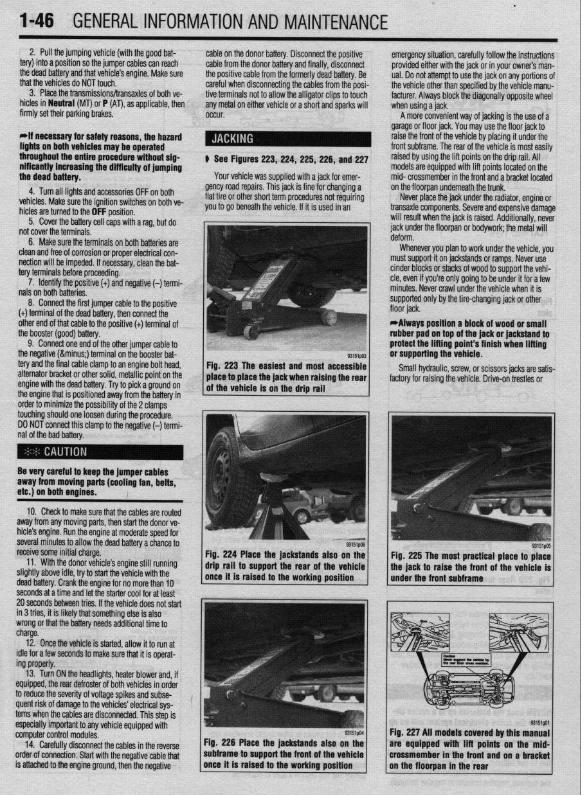
.
I-46 GENERALINFORMATIONAND MAINTENANCE 2. Pull the jumping vehicle (with the good bat-
tery) into a position so the jumper cables can reach the dead battery and that vehicle’s engine. Make sure that the vehicles do NOT touch.
3. Place the transmissions/transaxles of both ve- hicles in Neutral (MT) or P (AT), as applicable, then firmly set their parking brakes.
*ff necessary for safety reasons, the hazard lights on both vehicles may be operated throughout the entire procedure without sig- nificantiy increasing the diff icuity of jumping the dead battery.
4. Turn all lights and accessories OFF on both vehicles. Make sure the ignition switches on both ve- hicles are turned to the OFF position.
5. Cover the battery cell caps with a rag, but do not cover the terminals.
6. Make sure the terminals on both batteries are clean and free of corrosion or proper electrical con- nection will be impeded. If necessary, clean the bat- tery terminals before proceeding.
7. Identify the positive (+) and negative (-) termi- nals on both batteries.
8. Connect the first jumper cable to the positive (t) terminal of the dead battery, then connect the other end of that cable to the positive (t) terminal of the booster (good) battery.
9. Connect one end of the other jumper cable to the negative (−) terminal on the booster bat- tery and the final cable clamp to an engine bolt head, alternator bracket or other solid, metallic point on the engine with the dead battery. Try to pick a ground on the engine that is positioned away from the battery in order to minimize the possibility of the 2 clamps touching should one loosen during the procedure. DO NOT connect this clamp to the negative (-) termi- nal of the bad battery.
cable on the donor battery. Disconnect the positive cable from the donor battery and finally, disconnect the positive cable from the formerly dead battery. Be careful when disconnecting the cables from the posi- tive terminals not to allow the alligator clips to touch any metal on either vehicle or a short and sparks will occur.
I
$ See Figures 223,224, 225,226, and 227
Your vehicle was supplied with a jack for emer- gency road repairs. This jack is fine for changing a flat tire or other short term procedures not requiring you to go beneath the vehicle. If it is used in an
emergency situation, carefully follow the instructions provided either with the jack or in your owners man- ual. Do not attempt to use the jack on any portions of the vehicle other than specified by the vehicle manu- facturer. Always block the diagonally opposite wheel when using a jack.
A more convenient way of jacking is the use of a garage or floor jack. You may use the floor jack to raise the front of the vehicle by placing it under the front subframe. The rear of the vehicle is most easily raised by using the lift points on the drip rail. All models are equipped with lift points located on the mid- crossmember in the front and a bracket located on the floorpan underneath the trunk.
Never place the jack under the radiator, engine or transaxle components. Severe and expensive damage will result when the jack is raised. Additionally, never jack under the floorpan or bodywork; the metal will
Whenever you plan to work under the vehicle, you must support it on jackstands or ramps. Never use cinder blocks or stacks of wood to support the vehi- cle, even if you’re only going to be under it for a few minutes. Never crawl under the vehicle when it is supported only by the tire-changing jack or other
*Always position a block of wood or small rubber pad on top of the jack or jackstand to protect the lifting point’s finish when lifting or supporting the vehicle.
Small hydraulic, screw, or scissors jacks are satis- factory for raising the vehicle. Drive-on trestles or
Be very careful to keep the jumper cables away from moving parts (cooling fan, belts, etc.) on both engines.
10. Check to make sure that the cables are routed away from any moving parts, then start the donor ve- hicle’s engine. Run the engine at moderate speed for several minutes to allow the dead battery a chance to receive some initial charge.
11. With the donor vehicle’s engine still running slightly above idle, try to start the vehicle with the dead battery. Crank the engine for no more than 10
&stands also on the Fig. 225 The most practical place to place front of the vehicle is
seconds at a time and let the starter cool for at least 20 seconds between tries. If the vehicle does not start in 3 tries, it is likely thatsomething else is also wrong or that the battery needs additional time to charge.
12. Once the vehicle is started, allow it to run at idle for a few seconds to make sure that it is operat- ing properly.
13. Turn ON the headlights, heater blower and, if equipped, the rear defroster of both vehicles in order to reduce the severity of voltage spikes and subse- quent risk of damage to the vehicles’ electrical sys- tems when the cables are disconnected. This step is especially important to any vehicle equipped with computer control modules.
14. Carefully disconnect the cables in the’reverse order of connection. Start with the negative cable that is attached to the engine ground, then the negative
Fig. 226 Place the jackstands also subframe to support the front of the
Fig. 227 All models covered by this are equipped with lift points on t crossmember in the front and on a

GENERAL INFORMATION AND MAINTENANCE 1-47
ramps are also a handy and safe way to both raise l When the drive wheels are to remain on the and support the vehicle. Be careful though, some ground, leave the vehicle in gear to help prevent it ramps may be too steep to drive your vehicle onto The following safety points cannot be overempha- from rolling. without scraping the front bottom panels. Never sup- sized: l Always use jackstands to support the vehicle port the vehicle on any suspension member (unless l Always block the opposite wheel or wheels to when you are working underneath. Place the stands specifically instructed to do so by a repair manual) or keep the vehicle from rolling off the jack. beneath the vehrcle’s jacking brackets Before climb- by an underbody panel. l When raising the front of the vehicle, firmly ap- ing underneath, rock the vehicle a bit to make sure it
ply the parking brake. is firmly supported.
SCHEDULED MAINTENANCE INTERVALS (MITSUBISHI DIAMANTE, GALANT, & MIRAGE)
VEHICLE MILEAGE INTERVAL (x1000)
7.5 15 22.5 30 37.5 45 52.5 60 67.5 75 62.5 90 97.5
J J J 4 J J 4 4 4 J J J 4
4 J J J J 4
TO BE
Ball loints &steering linkage S/I J J J
seals
Dnve belt(s) S/I 4 4 J
Fvha,,rt cvctom $/I J J J LmI,..“w. “,YL”,‘.
Fuel hoses
+
Manual transaxle oil (Galant)
connectlon & fuel tank filler
R. Replace S/I - Sefwce or Inspect
FREQUENT OPERATION MAINTENANCE (SEVERE SERVICE) II a vehicle is operated under any of the following conditions it is considered severe service:
- Extremely dusty areas.
- 50% or more of the vehicle operation is in 32% (WF) or higher temperatures, or constant opsralion in
temperatures below 0% (32°F).
- Prolonged idling (vehicle operation in stop and go traffic).
_ Frequent short running periods (engine does not warm to normal operating temfwatures).
- Police, taxi, delivery usage or trailer towing usage.
0118 011 filter change-change every 3CQO miles.
Disc brake pads - sewce or Inspect ever 6COO miles
AN hlter element _ setwe or inspect every 15,000 miles.
Automatic transaxle lluld 8 filter . replace every 15,COO m&s.
Rear drum brake Ikmngs & rear wheel cylinders (Galant & Mirage)
Spark plugs (except Dlamante wlplabnum tip) - replace every 15,COO miles.
Manual transaxle 011 (mcludlng transfer (Galant & Mirage). replace every 30,000 miles.

1-48 GENERALINFORMATIONAND MAINTENANCE
CAPACITIES Engine Drive