cg tutorial final output - nvidiadownload.nvidia.com/developer/cg/cg_tutorial/chapter_1.pdf1.1.1 a...
TRANSCRIPT
1.1 What Is Cg?1
Introduction
Chapter 1
This chapter has the following four sections:
• “What Is Cg?” introduces the Cg programming language.
• “Vertices, Fragments, and the Graphics Pipeline” describes the data flow ofmodern graphics hardware and explains how Cg fits into this data flow.
• “Cg’s Historical Development” provides some background on how Cg wasdeveloped.
• “The Cg Environment” explains how applications go about using Cg programsthrough the Cg runtime and existing 3D application programming interfaces(APIs).
1.1 What Is Cg?
This book teaches you how to use a programming language called Cg. The Cg lan-guage makes it possible for you to control the shape, appearance, and motion of ob-jects drawn using programmable graphics hardware. It marries programmatic controlof these attributes with the incredible speed and capabilities of today’s graphics proces-sors. Never before have computer graphics practitioners, whether artists or program-mers, had so much control over the real-time images they generate.
Cg provides developers with a complete programming platform that is easy to use andenables the fast creation of special effects and real-time cinematic-quality experienceson multiple platforms. By providing a new level of abstraction, Cg removes the needfor developers to program directly to the graphics hardware assembly language, and

2
thereby more easily target OpenGL, DirectX, Windows, Linux, Macintosh OS X, andconsole platforms such as the Xbox. Cg was developed in close collaboration withMicrosoft Corporation and is compatible with both the OpenGL API and Microsoft’sHigh-Level Shading Language (HLSL) for DirectX 9.0.
Cg stands for “C for graphics.” The C programming language is a popular, general-purpose language invented in the 1970s. Because of its popularity and clean design, Cprovided the basis for several subsequent programming languages. For example, C++and Java base their syntax and structure largely on C. The Cg language bases itself onC as well. If you are familiar with C or one of the many languages derived from C,then Cg will be easy to learn.
On the other hand, if you are not familiar with C or even programming languages ingeneral but you enjoy computer graphics and want to learn something new, read onanyway. Cg programs tend to be short and understandable.
Much of this chapter is background that provides valuable context for understandingCg and using it effectively. On the other hand, you may find Cg is easier to learn bydoing. Feel free to skip to Chapter 2 at any time if you feel more comfortable justdiving into the tutorial.
1.1.1 A Language for Programming Graphics Hardware
Cg is different from C, C++, and Java because it is very specialized. No one will everwrite a spreadsheet or word processor in Cg. Instead, Cg targets the ability to pro-grammatically control the shape, appearance, and motion of objects rendered usinggraphics hardware. Broadly, this type of language is called a shading language. How-ever, Cg can do more than just shading. For example, Cg programs can perform phys-ical simulation, compositing, and other nonshading tasks.
Think of a Cg program as a detailed recipe for how to render an object by using pro-grammable graphics hardware. For example, you can write a Cg program to make asurface appear bumpy or to animate a virtual character. Later, in Section 1.3, you willlearn more about the history of shading languages and where Cg fits into this history.
1.1.2 Cg’s Data-Flow Model
In addition to being specialized for graphics, Cg and other shading languages are dif-ferent from conventional programming languages because they are based on a data-
Chapter 1: Introduction

3
flow computational model. In such a model, computation occurs in response to datathat flows through a sequence of processing steps.
Cg programs operate on vertices and fragments (think “pixels” for now if you do notknow what a fragment is) that are processed when rendering an image. Think of a Cgprogram as a black box into which vertices or fragments flow on one side, are some-how transformed, and then flow out on the other side. However, the box is not reallya black box because you get to determine, by means of the Cg programs you write,exactly what happens inside.
Every time a vertex is processed or the rasterizer generates a fragment while renderinga 3D scene, your corresponding vertex or fragment Cg program executes. Section 1.3explains Cg’s data-flow model further.
Most recent personal computers—and all recent game consoles—contain a graphicsprocessing unit (GPU) that is dedicated to graphics tasks such as transforming andrasterizing 3D models. Your Cg programs actually execute within the GPU of yourcomputer.
1.1.3 GPU Specialization and CPU Generalization
Whether or not a personal computer or game console has a GPU, there must be aCPU that runs the operating system and application programs. CPUs are, by design,general purpose. CPUs execute applications (for example, word processors and ac-counting packages) written in general-purpose languages, such as C++ or Java.
Because of the GPU’s specialized design, it is much faster at graphics tasks, such asrendering 3D scenes, than a general-purpose CPU would be. New GPUs process tensof millions of vertices per second and rasterize hundreds of millions or even billions offragments per second. Future GPUs will be even speedier. This is overwhelminglyfaster than the rate at which a CPU could process a similar number of vertices andfragments. However, the GPU cannot execute the same arbitrary, general-purposeprograms that a CPU can.
The specialized, high-performance nature of the GPU is why Cg exists. General-purpose programming languages are too open-ended for the specialized task of pro-cessing vertices and fragments. In contrast, the Cg language is fully dedicated to thistask. Cg also provides an abstract execution model that matches the GPU’s executionmodel. You will learn about the unique execution model of GPUs in Section 1.2.
1.1 What Is Cg?

4
1.1.4 The Performance Rationale for Cg
To sustain the illusion of interactivity, a 3D application needs to maintain an anima-tion rate of 15 or more images per second. Generally, we consider 60 or more framesper second to be “real time,” the rate at which interaction with applications appears tooccur instantaneously. The computer’s display may have a million or more pixels thatrequire redrawing. For 3D scenes, the GPU typically processes every pixel on thescreen many times to account for how objects occlude each other, or to improve theappearance of each pixel. This means that real-time 3D applications can require hun-dreds of millions of pixel updates per second. Along with the required pixel process-ing, 3D models are composed of vertices that must be transformed properly beforethey are assembled into polygons, lines, and points that will be rasterized into pixels.This can require transforming tens of millions of vertices per second.
Moreover, this graphical processing happens in addition to the considerable amount ofeffort required of the CPU to update the animation for each new image. The reality isthat we need both the CPU and the GPU’s specialized graphics-oriented capabilities.Both are required to render scenes at the interactive rates and quality standards thatusers of 3D applications and games demand. This means a developer can write a 3Dapplication or game in C++ and then use Cg to make the most of the GPU’s addi-tional graphics horsepower.
1.1.5 Coexistence with Conventional Languages
In no way does Cg replace any existing general-purpose languages. Cg is an auxiliarylanguage, designed specifically for GPUs. Programs written for the CPU in conven-tional languages such as C or C++ can use the Cg runtime (described in Section 1.4.2)to load Cg programs for GPUs to execute. The Cg runtime is a standard set of subrou-tines used to load, compile, manipulate, and configure Cg programs for execution bythe GPU. Applications supply Cg programs to instruct GPUs on how to accomplishthe programmable rendering effects that would not otherwise be possible on a CPU atthe rendering rates a GPU is capable of achieving.
Cg enables a specialized style of parallel processing. While your CPU executes a con-ventional application, that application also orchestrates the parallel processing of ver-tices and fragments on the GPU, by programs written in Cg.
If a real-time shading language is such a good idea, why didn’t someone invent Cgsooner? The answer has to do with the evolution of computer graphics hardware. Prior
Chapter 1: Introduction

5
to 2001, most computer graphics hardware—certainly the kind of inexpensive graph-ics hardware in PCs and game consoles—was hard-wired to the specific tasks of vertexand fragment processing. By “hard-wired,” we mean that the algorithms were fixedwithin the hardware, as opposed to being programmable in a way that is accessible tographics applications. Even though these hard-wired graphics algorithms could beconfigured by graphics applications in a variety of ways, the applications could notreprogram the hardware to do tasks unanticipated by the designers of the hardware.Fortunately, this situation has changed.
Graphics hardware design has advanced, and vertex and fragment processing units inrecent GPUs are truly programmable. Before the advent of programmable graphicshardware, there was no point in providing a programming language for it. Now thatsuch hardware is available, there is a clear need to make it easier to program this hard-ware. Cg makes it much easier to program GPUs in the same manner that C made itmuch easier to program CPUs.
Before Cg existed, addressing the programmable capabilities of the GPU was possibleonly through low-level assembly language. The cryptic instruction syntax and manualhardware register manipulation required by assembly languages—such as DirectX 8vertex and pixel shaders and some OpenGL extensions—made it a painful task formost developers. As GPU technology made longer and more complex assembly lan-guage programs possible, the need for a high-level language became clear. The exten-sive low-level programming that had been required to achieve optimal performancecould now be delegated to a compiler, which optimizes the code output and handlestedious instruction scheduling. Figure 1-1 is a small portion of a complex assemblylanguage fragment program used to represent skin. Clearly, it is hard to comprehend,particularly with the specific references to hardware registers.
In contrast, well-commented Cg code is more portable, more legible, easier to debug,and easier to reuse. Cg gives you the advantages of a high-level language such as Cwhile delivering the performance of low-level assembly code.
1.1.6 Other Aspects of Cg
Cg is a language for programming “in the small.” That makes it much simpler than amodern general-purpose language such as C++. Because Cg specializes in transformingvertices and fragments, it does not currently include many of the complex featuresrequired for massive software engineering tasks. Unlike C++ and Java, Cg does notsupport classes and other features used in object-oriented programming. Current Cg
1.1 What Is Cg?

6
implementations do not provide pointers or even memory allocation (though futureimplementations may, and keywords are appropriately reserved). Cg has absolutely nosupport for file input/output operations. By and large, these restrictions are not per-manent limitations in the language, but rather are indicative of the capabilities oftoday’s highest performance GPUs. As technology advances to permit more generalprogrammability on the GPU, you can expect Cg to grow appropriately. Because Cg isclosely based on C, future updates to Cg are likely to adopt language features from Cand C++.
Cg provides arrays and structures. It has all the flow-control constructs of a modernlanguage: loops, conditionals, and function calls.
Cg natively supports vectors and matrices because these data types and related mathoperations are fundamental to graphics and most graphics hardware directly supportsvector data types. Cg has a library of functions, called the Standard Library, that is
Chapter 1: Introduction
Figure 1-1. A Snippet of Assembly Language Code
. . .
DEFINE LUMINANCE = {0.299, 0.587, 0.114, 0.0};
TEX H0, f[TEX0], TEX4, 2D;
TEX H1, f[TEX2], TEX5, CUBE;
DP3X H1.xyz, H1, LUMINANCE;
MULX H0.w, H0.w, LUMINANCE.w;
MULX H1.w, H1.x, H1.x;
MOVH H2, f[TEX3].wxyz;
MULX H1.w, H1.x, H1.w;
DP3X H0.xyz, H2.xzyw, H0;
MULX H0.xyz, H0, H1.w;
TEX H1, f[TEX0], TEX1, 2D;
TEX H3, f[TEX0], TEX3, 2D;
MULX H0.xyz, H0, H3;
MADX H1.w, H1.w, 0.5, 0.5;
MULX H1.xyz, H1, {0.15, 0.15, 1.0, 0.0};
MOVX H0.w, H1.w;
TEX H1, H1, TEX7, CUBE;
TEX H3, f[TEX3], TEX2, 1D;
MULX H3.w, H0.w, H2.w;
MULX H3.xyz, H3, H3.w;
. . .

7
well suited for the kind of operations required for graphics. For example, the Cg Stan-dard Library includes a reflect function for computing reflection vectors.
Cg programs execute in relative isolation. This means that the processing of a particu-lar vertex or fragment has no effect on other vertices or fragments processed at thesame time. There are no side effects to the execution of a Cg program. This lack ofinterdependency among vertices and fragments makes Cg programs extremely wellsuited for hardware execution by highly pipelined and parallel hardware.
1.1.7 The Limited Execution Environment of Cg Programs
When you write a program in a language designed for modern CPUs using a modernoperating system, you expect that a more-or-less arbitrary program, as long as it iscorrect, will compile and execute properly. This is because CPUs, by design, executegeneral-purpose programs for which the overall system has more than sufficient re-sources.
However, GPUs are specialized rather than general-purpose, and the feature set ofGPUs is still evolving. Not everything you can write in Cg can be compiled to executeon a given GPU. Cg includes the concept of hardware “profiles,” one of which youspecify when you compile a Cg program. Each profile corresponds to a particularcombination of GPU architecture and graphics API. Your program not only must becorrect, but it also must limit itself to the restrictions imposed by the particular profileused to compile your Cg program. For example, a given fragment profile may limityou to no more than four texture accesses per fragment.
As GPUs evolve, additional profiles will be supported by Cg that correspond to morecapable GPU architectures. In the future, profiles will be less important as GPUs be-come more full-featured. But for now Cg programmers will need to limit programs toensure that they can compile and execute on existing GPUs. In general, future profileswill be supersets of current profiles, so that programs written for today’s profiles willcompile without change using future profiles.
This situation may sound limiting, but in practice the Cg programs shown in thisbook work on tens of millions of GPUs and produce compelling rendering effects.Another reason for limiting program size and scope is that the smaller and more effi-cient your Cg programs are, the faster they will run. Real-time graphics is often aboutbalancing increased scene complexity, animation rates, and improved shading. So it’salways good to maximize rendering efficiency through judicious Cg programming.
1.1 What Is Cg?

8
Keep in mind that the restrictions imposed by profiles are really limitations of currentGPUs, not Cg. The Cg language is powerful enough to express shading techniquesthat are not yet possible with all GPUs. With time, GPU functionality will evolve farenough that Cg profiles will be able to run amazingly complex Cg programs. Cg is alanguage for both current and future GPUs.
1.2 Vertices, Fragments, and the Graphics Pipeline
To put Cg into its proper context, you need to understand how GPUs render images.This section explains how graphics hardware is evolving and then explores the moderngraphics hardware-rendering pipeline.
1.2.1 The Evolution of Computer Graphics Hardware
Computer graphics hardware is advancing at incredible rates. Three forces are drivingthis rapid pace of innovation, as shown in Figure 1-2. First, the semiconductor indus-try has committed itself to doubling the number of transistors (the basic unit of com-puter hardware) that fit on a microchip every 18 months. This constant redoubling of
Chapter 1: Introduction
Figure 1-2. Forces Driving Graphics Hardware Innovation

9
computer power, historically known as Moore’s Law, means cheaper and faster com-puter hardware, and is the norm for our age.
The second force is the vast amount of computation required to simulate the worldaround us. Our eyes consume and our brains comprehend images of our 3D world atan astounding rate and with startling acuity. We are unlikely ever to reach a pointwhere computer graphics becomes a substitute for reality. Reality is just too real.Undaunted, computer graphics practitioners continue to rise to the challenge. Fortu-nately, generating images is an embarrassingly parallel problem. What we mean by“embarrassingly parallel” is that graphics hardware designers can repeatedly split upthe problem of creating realistic images into more chunks of work that are smallerand easier to tackle. Then hardware engineers can arrange, in parallel, the ever-greaternumber of transistors available to execute all these various chunks of work.
Our third force is the sustained desire we all have to be stimulated and entertainedvisually. This is the force that “connects” the source of our continued redoubling ofcomputer hardware resources to the task of approximating visual reality ever morerealistically than before.
As Figure 1-2 illustrates, these insights let us confidently predict that computer graph-ics hardware is going to get much faster. These innovations whet our collective ap-petite for more interactive and compelling 3D experiences. Satisfying this demand iswhat motivated the development of the Cg language.
1.2.2 Four Generations of Computer Graphics Hardware
In the mid-1990s, the world’s fastest graphics hardware consisted of multiple chipsthat worked together to render images and display them to a screen. The most complexcomputer graphics systems consisted of dozens of chips spread over several boards. Astime progressed and semiconductor technology improved, hardware engineers incor-porated the functionality of complicated multichip designs into a single graphics chip.This development resulted in tremendous economies of integration and scale.
You may be surprised to learn that the GPU now exceeds the CPU in the number oftransistors present in each microchip. Transistor count is a rough measure of howmuch computer hardware is devoted to a microchip. For example, Intel packed its 2.4GHz Pentium 4 with 55 million transistors; NVIDIA used over 125 million transis-tors in the original GeForce FX GPU.
1.2 Vertices, Fragments, and the Graphics Pipeline

10
NVIDIA introduced the term “GPU” in the late 1990s when the legacy term “VGAcontroller” was no longer an accurate description of the graphics hardware in a PC.IBM had introduced Video Graphics Array (VGA) hardware in 1987. At that time,the VGA controller was what we now call a “dumb” frame buffer. This meant that theCPU was responsible for updating all the pixels. Today the CPU rarely manipulatespixels directly. Instead, graphics hardware designers build the “smarts” of pixel updatesinto the GPU.
Industry observers have identified four generations of GPU evolution so far. Eachgeneration delivers better performance and evolving programmability of the GPUfeature set. Each generation also influences and incorporates the functionality of thetwo major 3D programming interfaces, OpenGL and DirectX. OpenGL is an openstandard for 3D programming for Windows, Linux, UNIX, and Macintosh comput-ers. DirectX is an evolving set of Microsoft multimedia programming interfaces, in-cluding Direct3D for 3D programming.
Pre-GPU Graphics AccelerationPrior to the introduction of GPUs, companies such as Silicon Graphics (SGI) andEvans & Sutherland designed specialized and expensive graphics hardware. The graph-ics systems developed by these companies introduced many of the concepts, such asvertex transformation and texture mapping, that we take for granted today. These sys-tems were very important to the historical development of computer graphics, butbecause they were so expensive, they did not achieve the mass-market success of single-chip GPUs designed for PCs and video game consoles. Today, GPUs are far more pow-erful and much cheaper than any prior systems.
First-Generation GPUsThe first generation of GPUs (up to 1998) includes NVIDIA’s TNT2, ATI’s Rage, and3dfx’s Voodoo3. These GPUs are capable of rasterizing pre-transformed triangles andapplying one or two textures. They also implement the DirectX 6 feature set. Whenrunning most 3D and 2D applications, these GPUs completely relieve the CPU fromupdating individual pixels. However, GPUs in this generation suffer from two clearlimitations. First, they lack the ability to transform vertices of 3D objects; instead,vertex transformations occur in the CPU. Second, they have a quite limited set ofmath operations for combining textures to compute the color of rasterized pixels.
Chapter 1: Introduction

11
Second-Generation GPUsThe second generation of GPUs (1999–2000) includes NVIDIA’s GeForce 256 andGeForce2, ATI’s Radeon 7500, and S3’s Savage3D. These GPUs offload 3D vertextransformation and lighting (T&L) from the CPU. Fast vertex transformation was oneof the key capabilities that differentiated high-end workstations from PCs prior to thisgeneration. Both OpenGL and DirectX 7 support hardware vertex transformation.Although the set of math operations for combining textures and coloring pixels ex-panded in this generation to include cube map textures and signed math operations,the possibilities are still limited. Put another way, this generation is more configurable,but still not truly programmable.
Third-Generation GPUsThe third generation of GPUs (2001) includes NVIDIA’s GeForce3 and GeForce4 Ti,Microsoft’s Xbox, and ATI’s Radeon 8500. This generation provides vertex program-mability rather than merely offering more configurability. Instead of supporting theconventional transformation and lighting modes specified by OpenGL and DirectX 7,these GPUs let the application specify a sequence of instructions for processing ver-tices. Considerably more pixel-level configurability is available, but these modes arenot powerful enough to be considered truly programmable. Because these GPUs sup-port vertex programmability but lack true pixel programmability, this generation istransitional. DirectX 8 and the multivendor ARB_vertex_program OpenGL exten-sion expose vertex-level programmability to applications. DirectX 8 pixel shaders andvarious vendor-specific OpenGL extensions expose this generation’s fragment-levelconfigurability.
Fourth-Generation GPUsThe fourth and current generation of GPUs (2002 and on) includes NVIDIA’sGeForce FX family with the CineFX architecture and ATI’s Radeon 9700. TheseGPUs provide both vertex-level and pixel-level programmability. This level of pro-grammability opens up the possibility of offloading complex vertex transformationand pixel-shading operations from the CPU to the GPU. DirectX 9 and variousOpenGL extensions expose the vertex-level and pixel-level programmability of theseGPUs. This is the generation of GPUs where Cg gets really interesting. Table 1-1 listsselected NVIDIA GPUs representing these various GPU generations.
1.2 Vertices, Fragments, and the Graphics Pipeline

12
The table uses the following terms:
• Process—the minimum feature size in microns (µ, millionths of a meter) for thesemiconductor process used to fabricate each microchip
• Transistors—an approximate measure, in millions (M), of the chips’ design andmanufacturing complexity
• Antialiasing fill rate—a GPU’s ability to fill pixels, measured in millions (M) of 32-bit RGBA pixels per second, assuming two-sample antialiasing; numbers in italicsindicate fill rates that are de-rated because the hardware lacks true antialiased ren-dering
• Polygon rate—a GPU’s ability to draw triangles, measured in millions (M) of trian-gles per second
The notes highlight the most significant improvements in each design. Performancerates may not be comparable with designs from other hardware vendors.
Future GPUs will further generalize the programmable aspects of current GPUs, andCg will make this additional programmability easy to use.
Chapter 1: Introduction
Generation Year Product Name Process TransistorsAntialiasingFill Rate
PolygonRate Note
First Late 1998 RIVA TNT 0.25 µ 7 M 50 M 6 M 1
First Early 1999 RIVA TNT2 0.22 µ 9 M 75 M 9 M 2
Second Late 1999 GeForce 256 0.22 µ 23 M 120 M 15 M 3
Second Early 2000 GeForce2 0.18 µ 25 M 200 M 25 M 4
Third Early 2001 GeForce3 0.15 µ 57 M 800 M 30 M 5
Third Early 2002 GeForce4 Ti 0.15 µ 63 M 1200 M 60 M 6
Fourth Early 2003 GeForce FX 0.13 µ 125 M 2000 M 200 M 7
Notes1. Dual texture DirectX 62. AGP 4×3. Fixed-function vertex hardware, register combiners, cube maps, DirectX 74. Performance, double data-rate (DDR) memory5. Vertex programs, quad-texturing, texture shaders, DirectX 86. Performance, antialiasing7. Massive vertex and fragment programmability, floating-point pixels, DirectX 9, AGP 8×
Table 1-1. Features and Performance Evolution of Selected NVIDIA GPUs, by Generation

13
1.2.3 The Graphics Hardware Pipeline
A pipeline is a sequence of stages operating in parallel and in a fixed order. Each stagereceives its input from the prior stage and sends its output to the subsequent stage.Like an assembly line where dozens of automobiles are manufactured at the sametime, with each automobile at a different stage of the line, a conventional graphicshardware pipeline processes a multitude of vertices, geometric primitives, and frag-ments in a pipelined fashion.
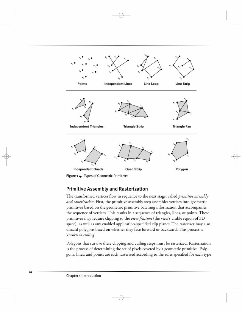
Figure 1-3 shows the graphics hardware pipeline used by today’s GPUs. The 3D appli-cation sends the GPU a sequence of vertices batched into geometric primitives: typi-cally polygons, lines, and points. As shown in Figure 1-4, there are many ways tospecify geometric primitives.
Every vertex has a position but also usually has several other attributes such as a color,a secondary (or specular) color, one or multiple texture coordinate sets, and a normalvector. The normal vector indicates what direction the surface faces at the vertex, andis typically used in lighting calculations.
Vertex TransformationVertex transformation is the first processing stage in the graphics hardware pipeline.Vertex transformation performs a sequence of math operations on each vertex. Theseoperations include transforming the vertex position into a screen position for use bythe rasterizer, generating texture coordinates for texturing, and lighting the vertex todetermine its color. We will explain many of these tasks in subsequent chapters.
1.2 Vertices, Fragments, and the Graphics Pipeline
Figure 1-3. The Graphics Hardware Pipeline
14
Primitive Assembly and RasterizationThe transformed vertices flow in sequence to the next stage, called primitive assemblyand rasterization. First, the primitive assembly step assembles vertices into geometricprimitives based on the geometric primitive batching information that accompaniesthe sequence of vertices. This results in a sequence of triangles, lines, or points. Theseprimitives may require clipping to the view frustum (the view’s visible region of 3Dspace), as well as any enabled application-specified clip planes. The rasterizer may alsodiscard polygons based on whether they face forward or backward. This process isknown as culling.
Polygons that survive these clipping and culling steps must be rasterized. Rasterizationis the process of determining the set of pixels covered by a geometric primitive. Poly-gons, lines, and points are each rasterized according to the rules specified for each type
Chapter 1: Introduction
Figure 1-4. Types of Geometric Primitives

15
of primitive. The results of rasterization are a set of pixel locations as well as a set offragments. There is no relationship between the number of vertices a primitive has andthe number of fragments that are generated when it is rasterized. For example, a trian-gle made up of just three vertices could take up the entire screen, and therefore gener-ate millions of fragments!
Earlier, we told you to think of a fragment as a pixel if you did not know preciselywhat a fragment was. At this point, however, the distinction between a fragment and apixel becomes important. The term pixel is short for “picture element.” A pixel repre-sents the contents of the frame buffer at a specific location, such as the color, depth,and any other values associated with that location. A fragment is the state requiredpotentially to update a particular pixel.
The term “fragment” is used because rasterization breaks up each geometric primitive,such as a triangle, into pixel-sized fragments for each pixel that the primitive covers. Afragment has an associated pixel location, a depth value, and a set of interpolated pa-rameters such as a color, a secondary (specular) color, and one or more texture coordi-nate sets. These various interpolated parameters are derived from the transformedvertices that make up the particular geometric primitive used to generate thefragments. You can think of a fragment as a “potential pixel.” If a fragment passes thevarious rasterization tests (in the raster operations stage, which is described shortly),the fragment updates a pixel in the frame buffer.
Interpolation, Texturing, and ColoringOnce a primitive is rasterized into a collection of zero or more fragments, the interpo-lation, texturing, and coloring stage interpolates the fragment parameters as necessary,performs a sequence of texturing and math operations, and determines a final colorfor each fragment. In addition to determining the fragment’s final color, this stagemay also determine a new depth or may even discard the fragment to avoid updatingthe frame buffer’s corresponding pixel. Allowing for the possibility that the stage maydiscard a fragment, this stage emits one or zero colored fragments for every input frag-ment it receives.
Raster OperationsThe raster operations stage performs a final sequence of per-fragment operations imme-diately before updating the frame buffer. These operations are a standard part ofOpenGL and Direct3D. During this stage, hidden surfaces are eliminated through a
1.2 Vertices, Fragments, and the Graphics Pipeline

16
process known as depth testing. Other effects, such as blending and stencil-based shad-owing, also occur during this stage.
The raster operations stage checks each fragment based on a number of tests, includ-ing the scissor, alpha, stencil, and depth tests. These tests involve the fragment’s finalcolor or depth, the pixel location, and per-pixel values such as the depth value andstencil value of the pixel. If any test fails, this stage discards the fragment without up-dating the pixel’s color value (though a stencil write operation may occur). Passing thedepth test may replace the pixel’s depth value with the fragment’s depth. After thetests, a blending operation combines the final color of the fragment with the corre-sponding pixel’s color value. Finally, a frame buffer write operation replaces the pixel’scolor with the blended color. Figure 1-5 shows this sequence of operations.
Figure 1-5 shows that the raster operations stage is actually itself a series of pipelinestages. In fact, all of the previously described stages can be broken down into substagesas well.
Visualizing the Graphics PipelineFigure 1-6 depicts the stages of the graphics pipeline. In the figure, two triangles arerasterized. The process starts with the transformation and coloring of vertices. Next,the primitive assembly step creates triangles from the vertices, as the dotted lines indi-
Chapter 1: Introduction
Figure 1-5. Standard OpenGL and Direct3D Raster Operations

17
cate. After this, the rasterizer “fills in” the triangles with fragments. Finally, the registervalues from the vertices are interpolated and used for texturing and coloring. Noticethat many fragments are generated from just a few vertices.
1.2.4 The Programmable Graphics Pipeline
The dominant trend in graphics hardware design today is the effort to expose moreprogrammability within the GPU. Figure 1-7 shows the vertex processing and frag-ment processing stages in the pipeline of a programmable GPU.
Figure 1-7 shows more detail than Figure 1-3, but more important, it shows the vertexand fragment processing broken out into programmable units. The programmable
1.2 Vertices, Fragments, and the Graphics Pipeline
Figure 1-6. Visualizing the Graphics Pipeline
Figure 1-7. The Programmable Graphics Pipeline

18
vertex processor is the hardware unit that runs your Cg vertex programs, whereas theprogrammable fragment processor is the unit that runs your Cg fragment programs.
As explained in Section 1.2.2, GPU designs have evolved, and the vertex and fragmentprocessors within the GPU have transitioned from being configurable to being pro-grammable. The descriptions in the next two sections present the critical functionalfeatures of programmable vertex and fragment processors.
The Programmable Vertex ProcessorFigure 1-8 shows a flow chart for a typical programmable vertex processor. The data-flow model for vertex processing begins by loading each vertex’s attributes (such as
Chapter 1: Introduction
Figure 1-8. Programmable Vertex Processor Flow Chart

19
position, color, texture coordinates, and so on) into the vertex processor. The vertexprocessor then repeatedly fetches the next instruction and executes it until the vertexprogram terminates. Instructions access several distinct sets of registers banks thatcontain vector values, such as position, normal, or color. The vertex attribute registersare read-only and contain the application-specified set of attributes for the vertex. Thetemporary registers can be read and written and are used for computing intermediateresults. The output result registers are write-only. The program is responsible for writ-ing its results to these registers. When the vertex program terminates, the output resultregisters contain the newly transformed vertex. After triangle setup and rasterization,the interpolated values for each register are passed to the fragment processor.
Most vertex processing uses a limited palette of operations. Vector math operations onfloating-point vectors of two, three, or four components are necessary. These opera-tions include add, multiply, multiply-add, dot product, minimum, and maximum.Hardware support for vector negation and component-wise swizzling (the ability toreorder vector components arbitrarily) generalizes these vector math instructions toprovide negation, subtraction, and cross products. Component-wise write maskingcontrols the output of all instructions. Combining reciprocal and reciprocal squareroot operations with vector multiplication and dot products, respectively, enablesvector-by-scalar division and vector normalization. Exponential, logarithmic, andtrigonometric approximations facilitate lighting, fog, and geometric computations.Specialized instructions can make lighting and attenuation functions easier to compute.
Further functionality, such as relative addressing of constants and flow-control supportfor branching and looping, is also available in more recent programmable vertexprocessors.
The Programmable Fragment ProcessorProgrammable fragment processors require many of the same math operations as pro-grammable vertex processors do, but they also support texturing operations. Texturingoperations enable the processor to access a texture image using a set of texture coordi-nates and then to return a filtered sample of the texture image.
Newer GPUs offer full support for floating-point values; older GPUs have more lim-ited fixed-point data types. Even when floating-point operations are available, frag-ment operations are often more efficient when using lower-precision data types. GPUsmust process so many fragments at once that arbitrary branching is not available incurrent GPU generations, but this is likely to change over time as hardware evolves.
1.2 Vertices, Fragments, and the Graphics Pipeline

20
Cg still allows you to write fragment programs that branch and iterate by simulatingsuch constructs with conditional assignment operations or loop unrolling.
Figure 1-9 shows the flow chart for a current programmable fragment processor. Aswith a programmable vertex processor, the data flow involves executing a sequence ofinstructions until the program terminates. Again, there is a set of input registers. How-ever, rather than vertex attributes, the fragment processor’s read-only input registerscontain interpolated per-fragment parameters derived from the per-vertex parametersof the fragment’s primitive. Read/write temporary registers store intermediate values.Write operations to write-only output registers become the color and optionally thenew depth of the fragment. Fragment program instructions include texture fetches.
Chapter 1: Introduction
Figure 1-9. Programmable Fragment Processor Flow Chart

21
1.2.5 Cg Provides Vertex and Fragment Programmability
These two programmable processors in your GPU require you, the application pro-grammer, to supply a program for each processor to execute. What Cg provides is alanguage and a compiler that can translate your shading algorithm into a form thatyour GPU’s hardware can execute. With Cg, rather than program at the level shown inFigures 1-8 and 1-9, you can program in a high-level language very similar to C.
1.3 Cg’s Historical Development
Cg’s heritage comes from three sources, as shown in Figure 1-10. First, Cg bases itssyntax and semantics on the general-purpose C programming language. Second, Cgincorporates many concepts from offline shading languages such as the RenderManShading Language, as well as prior hardware shading languages developed by acade-mia. Third, Cg bases its graphics functionality on the OpenGL and Direct3D pro-gramming interfaces for real-time 3D.
1.3 Cg’s Historical Development
Figure 1-10. Sources of Cg’s Technology Heritage

22
Figure 1-11 shows the general-purpose programming languages, 3D application pro-gramming interfaces, and shading languages that inspired Cg’s development.
Earlier, we mentioned how Cg leverages C’s syntax and semantics. Over the course ofthis book, you will find that Cg mostly does what C programmers expect. Cg differsfrom C in situations where either Cg’s specialization for GPUs or performance justifiesa change.
1.3.1 Microsoft and NVIDIA’s Collaboration to Develop Cg and HLSL
NVIDIA and Microsoft collaborated to develop the Cg language. Microsoft calls itsimplementation High-Level Shading Language, or HLSL for short. HLSL and Cg are
Chapter 1: Introduction
Figure 1-11. Inspirations for Cg’s Development

23
the same language but reflect the different names each company uses to identify thelanguage and its underlying technology. HLSL is a part of Microsoft’s DirectX Graph-ics, a component of the DirectX 9 multimedia framework. Direct3D is the 3D compo-nent of Microsoft’s DirectX Graphics. Cg is independent of the 3D programminginterface and fully integrates with either Direct3D or OpenGL. A properly written Cgapplication can be written once and then work with either OpenGL or Direct3D.
This flexibility means that NVIDIA’s Cg implementation provides a way to authorprograms that work with both dominant 3D programming interfaces and whateveroperating system you choose. Cg works whether you choose Windows, Linux, MacOS X, a game console, or embedded 3D hardware as your 3D computing platform.Cg programs work with hardware from multiple hardware vendors because Cg layerscleanly upon either Direct3D or OpenGL. Cg programs work on programmableGPUs from all the major graphics hardware vendors, such as 3Dlabs, ATI, Matrox,and NVIDIA.
The multivendor, cross-API, and multiplatform nature of the Cg language makes itthe best choice when writing programs for programmable GPUs.
1.3.2 Noninteractive Shading Languages
The RenderMan Interface Standard describes the best-known shading language fornoninteractive shading. Pixar developed the language in the late 1980s to generatehigh-quality computer animation with sophisticated shading for films and commer-cials. Pixar has created a complete rendering system with its implementation of theRenderMan Interface Standard, the offline renderer PRMan (PhotoRealistic Render-Man). The RenderMan Shading Language is just one component of this system.
Shade TreesThe inspiration for the RenderMan Shading Language came from an earlier ideacalled shade trees. Rob Cook, then at Lucasfilm Ltd., which later spun off Pixar, pub-lished a SIGGRAPH paper about shade trees in 1984. A shade tree organizes variousshading operations as nodes within a tree structure. Figure 1-12 shows a shade tree forrendering a copper surface. The leaf nodes are data inputs to the shade tree. The non-leaf nodes represent simple shading operations. During the process of rendering, therenderer evaluates the shade tree associated with a given surface to determine the colorof the surface in the rendered image. To evaluate a shade tree, a renderer performs the
1.3 Cg’s Historical Development

24
shading operation associated with the topmost node in the shade tree. However, toevaluate a given node, the renderer must first evaluate the node’s child nodes. This ruleis applied recursively to evaluate the shade tree fully. The result of a shade tree evalua-tion at a given point on a surface is the color of that point.
Shade trees grew out of the realization that a single predefined shading model wouldnever be sufficient for all the objects and scenes one might want to render.
Shade tree diagrams are great for visualizing a data flow of shading operations. How-ever, if the shade trees are complex, their diagrams become unwieldy. Researchers atPixar and elsewhere recognized that each shade tree is a limited kind of program. Thisrealization provided the impetus for a new kind of programming language known as ashading language.
The RenderMan Shading LanguageThe RenderMan Shading Language grew out of shade trees and the realization thatopen-ended control of the appearance of rendered surfaces in the pursuit of photoreal-ism requires programmability.
Chapter 1: Introduction
Figure 1-12. A Shade Tree Example, Based on Rob Cook’s Original SIGGRAPH Paper

25
Today most offline renderers used in actual production have some type of support fora shading language. The RenderMan Shading Language is the most established andbest known for offline rendering, and it was significantly overhauled and extended inthe late 1990s.
Hardware-Amenable Shading LanguagesA hardware implementation of an algorithm is most efficient when the task decom-poses into a long sequence of stages in which each stage’s communication is limited toits prior stage and its subsequent stage (that is, when it can be pipelined).
The vertex-based and fragment-based pipeline described in Section 1.2 is extremelyamenable to hardware implementation. However, the Reyes algorithm used by Photo-Realistic RenderMan is not very suitable for efficient hardware implementation, pri-marily due to its higher-level geometry handling. Contemporary GPUs relycompletely on a graphics pipeline based on vertices and fragments.
Researchers at the University of North Carolina (UNC) began investigating program-mable graphics hardware in the mid-1990s, when UNC was developing a new pro-grammable graphics hardware architecture called PixelFlow. This project fostered anew line of computer graphics research into hardware-amenable shading languages byMarc Olano and others at UNC. Unfortunately, PixelFlow was too expensive andfailed commercially.
Subsequently, researchers at Silicon Graphics worked on a system to translate shadersinto multiple passes of OpenGL rendering. Although the targeted OpenGL hardwarewas not programmable in the way GPUs are today, the OpenGL Shader system or-chestrates numerous rendering passes to achieve a shader’s intended effect.
Researchers at Stanford University, including Kekoa Proudfoot, Bill Mark, SvetoslavTzvetkov, and Pat Hanrahan, began building a shading language designed specificallyfor second-generation and third-generation GPUs. This language, known as the Stan-ford Real-Time Shading Language (RTSL), could compile shaders written in RTSLinto one or more OpenGL rendering passes.
The research at Stanford inspired NVIDIA’s own effort to develop a commercial-quality hardware-amenable shading language. Bill Mark joined NVIDIA in 2001 tolead the effort to define and implement the shading language we now call Cg. Dur-ing this time, NVIDIA collaborated with Microsoft to agree on a common languagesyntax and feature set.
1.3 Cg’s Historical Development

26
1.3.3 Programming Interfaces for 3D Graphics
The third influence on Cg was the pair of standard 3D programming interfaces,OpenGL and Direct3D. The influence of these programming interfaces on Cg is on-going, as is explained in the next section.
1.4 The Cg Environment
Cg is just one component of the overall software and hardware infrastructure for ren-dering complex 3D scenes with programmable GPUs at real-time rates. This sectionexplains how Cg interacts with actual 3D applications and games.
1.4.1 Standard 3D Programming Interfaces: OpenGL and Direct3D
In the old days of 3D graphics on a PC (before there were GPUs), the CPU handledall the vertex transformation and pixel-pushing tasks required to render a 3D scene.The graphics hardware provided only the buffer of pixels that the hardware displayedto the screen. Programmers had to implement their own 3D graphics rendering algo-rithms in software. In a sense, everything about vertex and fragment processing backthen was completely programmable. Unfortunately, the CPU was too slow to producecompelling 3D effects.
These days, 3D applications no longer implement their own 3D rendering algorithmsusing the CPU; rather, they rely on either OpenGL or Direct3D, the two standard 3Dprogramming interfaces, to communicate rendering commands to the GPU.
OpenGLIn the early 1990s, Silicon Graphics developed OpenGL in coordination with an or-ganization called the OpenGL Architecture Review Board (ARB), which comprised allthe major computer graphics system vendors. Originally, OpenGL ran only on power-ful UNIX graphics workstations. Microsoft, a founding member of the ARB, thenimplemented OpenGL as a way to support 3D graphics for its Windows NT operat-ing system. Microsoft later added OpenGL support to Windows 95 and all of Mi-crosoft’s desktop operating systems.
Chapter 1: Introduction

27
OpenGL is not limited to a single operating or windowing system. In addition tosupporting UNIX workstations and Windows PCs, OpenGL is supported by Applefor its Macintosh personal computers. Linux users can use either the Mesa open-source implementation of OpenGL or a hardware-accelerated implementation such asNVIDIA’s OpenGL driver for Linux. This flexibility makes OpenGL the industry’sbest cross-platform programming interface for 3D graphics.
Over the last decade, OpenGL has evolved along with graphics hardware. OpenGL isextensible, meaning that OpenGL implementers can add new functionality toOpenGL in an incremental way. Today, scores of OpenGL extensions provide accessto all the latest GPU features. This includes ARB-standardized extensions for vertexand fragment programmability. As extensions are established, they are often rolled intothe core OpenGL standard so that the standard as a whole advances. At the time ofthis writing, the current version of OpenGL is 1.4. Ongoing work to evolve OpenGLis underway in various OpenGL ARB working groups. This work includes both as-sembly-level and high-level programmable interfaces. Because Cg operates as a layerabove such interfaces, it will continue to function with future revisions of OpenGL ina compatible manner.
Direct3DMicrosoft began developing the Direct3D programming interface about 1995 as partof its DirectX multimedia initiative. Direct3D is one of the programming interfacesthat make up DirectX. Microsoft introduced DirectX and Direct3D to jump-start theconsumer market for 3D graphics, particularly gaming, on Windows PCs. Microsoft’sXbox game console also supports Direct3D. Direct3D is the most popular graphicsAPI for games on Windows, due to its history of closely matching the capabilities ofavailable graphics hardware.
Every year or so, Microsoft has updated DirectX, including Direct3D, to keep up withthe rapid pace of PC hardware innovation. The current version of DirectX at the timeof this writing is DirectX 9, which includes HLSL, Microsoft’s implementation of thesame language syntax and constructs found in Cg.
3D Programming Interface DétenteA few years ago, OpenGL and Direct3D competed to see which programming inter-face would dominate, particularly in the domain of Windows PCs. The competitioncontinues to be good for both programming interfaces, and each has improved in
1.4 The Cg Environment

28
performance, quality, and functionality. In the area of GPU programmability that Cgaddresses, both programming interfaces have comparable capabilities. This is becauseboth OpenGL and Direct3D run on the same GPU hardware and the graphics hard-ware determines the available functionality and performance. OpenGL has a slightadvantage in functionality because hardware vendors are better able to expose theirentire feature set through OpenGL, though vendor-specific extensions do add somecomplexity for developers.
Most software developers now choose a 3D programming interface based on program-mer preference, history, and their target market and hardware platform, rather than ontechnical grounds.
Cg supports either programming interface. You can write Cg programs so that theywork with either the OpenGL or Direct3D programming interface. This is a hugeboon for 3D content developers. They can pair their 3D content with programs writ-ten in Cg and then render the content no matter what programming interface thefinal application uses for 3D rendering.
1.4.2 The Cg Compiler and Runtime
No GPU can execute Cg programs directly from their textual form. A process knownas compilation must translate Cg programs into a form that the GPU can execute.The Cg compiler first translates your Cg program into a form accepted by the applica-tion’s choice of 3D programming interface, either OpenGL or Direct3D. Then yourapplication transfers the OpenGL or Direct3D translation of your Cg program to theGPU using the appropriate OpenGL or Direct3D commands. The OpenGL or Direct3D driver performs the final translation into the hardware-executable form yourGPU requires.
The details of this translation depend on the combined capabilities of the GPU and3D programming interface. How a Cg program compiles its intermediate OpenGL orDirect3D form depends on the type and generation of GPU in your computer. It maybe that your GPU is not capable of supporting a particular valid Cg program becauseof limitations of the GPU itself. For example, your Cg fragment program will notcompile if your program accesses more texture units than your target GPU supports.
Chapter 1: Introduction
29
Support for Dynamic CompilationWhen you compile a program with a conventional programming language such as C orC++, compilation is an offline process. Your compiler compiles the program into anexecutable that runs directly on the CPU. Once compiled, your program does not needto be recompiled, unless you change the program code. We call this static compilation.
Cg is different because it encourages dynamic compilation, although static compilationis also supported. The Cg compiler is not a separate program but part of a libraryknown as the Cg runtime. 3D applications and games using Cg programs must linkwith the Cg runtime. Applications using Cg then call Cg runtime routines, all pre-fixed with the letters cg, to compile and manipulate Cg programs. Dynamic compila-tion allows Cg programs to be optimized for the particular model of GPU installed inthe user’s machine.
CgGL and CgD3D, the 3D-API-Specific Cg LibrariesIn addition to the core Cg runtime, Cg provides two closely related libraries. If yourapplication uses OpenGL, you will use the CgGL library to invoke the appropriateOpenGL routines to pass your translated Cg program to the OpenGL driver. Like-wise, if your application uses Direct3D, you will use the CgD3D library to invoke theappropriate Direct3D routines to pass your translated Cg program to the Direct3Ddriver. Normally, you would use either the CgGL or the CgD3D library, but not both,because most applications use either OpenGL or Direct3D, not both.
Compared with the core Cg runtime library that contains the Cg compiler, the CgGLand CgD3D libraries are relatively small. Their job is to make the appropriateOpenGL or Direct3D calls for you to configure Cg programs for execution. Thesecalls transfer a translated Cg program to the appropriate driver that will further trans-late the program into a form your GPU can execute. For the most part, the CgGL andCgD3D libraries have similar routines. The routines in the CgGL library begin withcgGL; the routines in the CgD3D library begin with cgD3D.
How the Cg Runtime Fits into Your ApplicationFigure 1-13 shows how a typical 3D application uses the Cg libraries. If you are aprogrammer, you will want to learn more about the Cg runtime and the specific li-brary for the 3D API your application uses to render 3D graphics. Most of this bookfocuses on the Cg language itself and on how to write Cg programs, but Appendix Bhas more information about the Cg runtime library.
1.4 The Cg Environment

30
1.4.3 The CgFX Toolkit and File Format
Cg programs need 3D models, textures, and other data to operate on. A Cg programwithout any associated data is useless. Cg programs and data also require the correct3D programming interface configuration and state. It is often helpful to have a way tobundle all the information required to render a 3D model, including its associated Cgprogram.
What CgFX ProvidesCgFX is a standardized file format for representing complete effects and appearances.As they did with Cg, Microsoft and NVIDIA collaborated to develop the CgFX for-mat. CgFX files are text-based, with a syntax that is a superset of Cg’s, and may con-tain any number of Cg programs. The .fx suffix identifies CgFX files. A CgFX filedescribes the complete render state for a particular effect: multiple passes, texturestates, and any number of individual vertex and fragment programs may be defined tocreate a complete appearance or effect. An accompanying development toolkit is pro-vided for using and parsing CgFX files. The toolkit exposes user-interface hooks tohost applications, so that CgFX-aware applications can automatically supply meaning-ful controls and semantics to users and developers alike.
Chapter 1: Introduction
Figure 1-13. How Cg Fits into a Standard Cg Application

31
Cg programs describe the vertex or fragment processing that takes place in a singlerendering pass, but some complex shading algorithms require multiple renderingpasses. CgFX offers a format to encode complex multipass effects, including designat-ing which Cg program is used for each rendering pass.
More specifically, CgFX supports three additional capabilities beyond what the coreCg language supports:
1. CgFX provides a mechanism for specifying multiple rendering passes and optionalmultiple implementations for a single effect.
2. CgFX allows you to specify nonprogrammable rendering states, such as alpha-testmodes and texture-filtering. The settings for these render states may take the formof simple expressions, which are evaluated on the CPU when the effect is initialized.
3. CgFX allows annotations to be added to shaders and shader parameters. Theseannotations provide additional information to applications, including contentcreation applications. For example, an annotation can specify the allowed range ofvalues for a shader parameter.
Multiple Shader InstancingThe CgFX file format encapsulates multiple implementations of Cg programs for agiven shader. This means you can have one Cg shader program written for a third-generation or fourth-generation GPU, while also including a simpler program thatsupports a less capable, second-generation GPU. An application loading the CgFX filecan determine at runtime the most appropriate shader implementation to use basedon the computer’s available GPU.
Multiple instancing of Cg programs with CgFX is one way to address the functionalvariations in GPUs of different generations or different hardware vendors. Multipleinstancing also lets you develop a Cg program specialized for a particular 3D API—forexample, if OpenGL exposes extra functionality through an extension. Cg programsspecialized for Direct3D, standard OpenGL, or OpenGL with extensions can all becontained in a single CgFX file.
CgFX and Digital Content CreationThe CgFX Toolkit consists of the CgFX compiler, which supports the full CgFXsyntax; the CgFX runtime API, for loading and manipulating CgFX files; and plug-in modules for major digital content creation (DCC) applications such as
1.4 The Cg Environment

32
Alias|Wavefront’s Maya and Discreet’s 3ds max. Figure 1-14 shows these applicationsmaking use of CgFX. Softimage|XSI 3.0 provides direct support for Cg compilationin its Render Tree.
Prior to CgFX, there was no standard way for a DCC application to export 3D con-tent with all the associated shading knowledge necessary to render the content in realtime. Now the major DCC applications use CgFX in their content creation processand support the CgFX file format. This means that CgFX can significantly improvethe artistic workflow from DCC applications to real-time games and other 3D appli-cations. Using CgFX, artists can view and tweak Cg shaders and associated 3D con-tent to see, from within the DCC tool of their choice, how their work will appear in a3D game or application.
Chapter 1: Introduction
Figure 1-14. Digital Content Creation Applications That Use Cg and CgFX
33
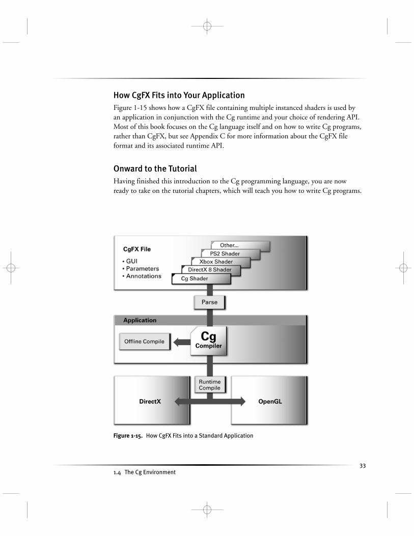
How CgFX Fits into Your ApplicationFigure 1-15 shows how a CgFX file containing multiple instanced shaders is used byan application in conjunction with the Cg runtime and your choice of rendering API.Most of this book focuses on the Cg language itself and on how to write Cg programs,rather than CgFX, but see Appendix C for more information about the CgFX fileformat and its associated runtime API.
Onward to the TutorialHaving finished this introduction to the Cg programming language, you are nowready to take on the tutorial chapters, which will teach you how to write Cg programs.
1.4 The Cg Environment
Figure 1-15. How CgFX Fits into a Standard Application

34
1.5 Exercises
The exercises at the end of each chapter help you review your knowledge and developpractical programming skills.
1. Answer this: Name two standard 3D programming interfaces for which you cancompile Cg programs. What operating systems does each programming interfacesupport?
2. Answer this: What are the major stages of the graphics pipeline? In what order arethe stages arranged?
3. Answer this: Where do vertex and fragment programs fit into the pipeline?
4. Answer this: What is a vertex? What is a fragment? Distinguish a fragment from apixel.
5. Try this yourself: We haven’t begun writing Cg programs yet (we’ll get there soonenough in the next chapter), so take a break and watch a good feature-length com-puter graphics animation such as Monsters, Inc.
1.6 Further Reading
Cg builds on a host of concepts in computer language design, computer hardwaredesign, and computer graphics. Doing justice to all these contributions in the contextof this tutorial is not always practical. What we attempt in the “Further Reading”section at the end of each chapter is to offer you pointers to learn more about thecontributions that underlie the topics in each chapter.
There are plenty of books on C. The C Programming Language, Third Edition (Pren-tice Hall, 2000), by Brian Kernighan and Dennis Ritchie, is a classic; the authorsinvented the C language. Cg includes concepts from both C and C++. There now mayactually be more books about C++ than about C. The classic C++ book is The C++Programming Language, Third Edition (Addison-Wesley, 2000), by Bjarne Stroustrup,who invented the language.
To learn more about the RenderMan Shading Language, read The RenderMan Com-panion: A Programmer’s Guide to Realistic Computer Graphics (Addison-Wesley, 1989),by Steve Upstill. Pat Hanrahan and Jim Lawson published a SIGGRAPH paper about
Chapter 1: Introduction

35
RenderMan called “A Language for Shading and Lighting Calculations” (ACM Press)in 1990.
Robert Cook’s 1984 SIGGRAPH paper titled “Shade Trees” (ACM Press) motivatedthe development of RenderMan.
The development of programmable graphics hardware and its associated languages hasbeen an active and fruitful research area for almost a decade. Anselmo Lastra, StevenMolnar, Marc Olano, and Yulan Wang at UNC published an early research paper in1995 titled “Real-Time Programmable Shading” (ACM Press). Researchers at UNCalso published several papers about their programmable PixelFlow graphics architec-ture. Marc Olano and Anselmo Lastra published a SIGGRAPH paper titled “A Shad-ing Language on Graphics Hardware: The PixelFlow Shading System” (ACM Press) in1998.
Kekoa Proudfoot, Bill Mark, Svetoslav Tzvetkov, and Pat Hanrahan published a SIG-GRAPH paper in 2001 titled “A Real-Time Procedural Shading System for Program-mable Graphics Hardware” (ACM Press) that describes a GPU-oriented shadinglanguage developed at Stanford.
Real-Time Rendering, Second Edition (A. K. Peters, 2002), written by Eric Haines andTomas Akenine-Möller, is an excellent resource for further information about graphicshardware and interactive techniques.
The OpenGL Graphics System: A Specification documents the OpenGL 3D program-ming interface. The best tutorial for learning OpenGL programming is the OpenGLProgramming Guide: The Official Guide to Learning OpenGL, Third Edition (Addison-Wesley, 1999), by Mason Woo, Jackie Neider, Tom Davis, and Dave Shreiner. Thewww.opengl.org Web site serves up much more information about OpenGL.
Documentation for the Direct3D programming interface is available from Microsoft’smsdn.microsoft.com Web site.
NVIDIA provides further information about the Cg runtime, CgFX, and Cg itself onits Developer Web site at developer.nvidia.com/Cg.
1.6 Further Reading