cfrd 17 - roy ruiz vásquez
DESCRIPTION
cfrdTRANSCRIPT
RD 2011 CFRD 17
The Second International Symposium on Rockfill Dams 1
REVENTAZÓN DAM GEOTECHNICAL DESIGN
Roy Ruiz Vázquez1, Eduardo Avilés Madrigal2
1 Instituto Costarricense de Electricidad, [email protected], 2 Instituto Costarricense de Electricidad, [email protected],
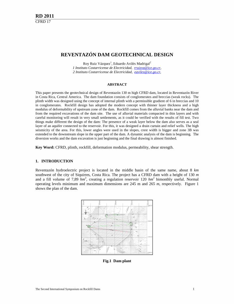
ABSTRACT This paper presents the geotechnical design of Reventazón 130 m high CFRD dam, located in Reventazón River in Costa Rica, Central America. The dam foundation consists of conglomerates and breccias (weak rocks). The plinth width was designed using the concept of internal plinth with a permissible gradient of 6 in breccias and 10 in conglomerates. Rockfill design has adopted the modern concept with thinner layer thickness and a high modulus of deformability of upstream zone of the dam. Rockfill comes from the alluvial banks near the dam and from the required excavations of the dam site. The use of alluvial materials compacted in thin layers and with careful monitoring will result in very small settlements, as it could be verified with the results of fill test. Two things make different the design of the dam: The presence of a weak layer below the dam also serves as a seal layer of an aquifer connected to the reservoir. For this, it was designed a drain curtain and relief wells. The high seismicity of the area. For this, lower angles were used in the slopes, crest width is bigger and zone 3B was extended to the downstream slope in the upper part of the dam. A dynamic analysis of the dam is beginning. The diversion works and the dam excavation is just beginning and the final drawing is almost finished. Key Word: CFRD, plinth, rockfill, deformation modulus, permeability, shear strength. 1. INTRODUCTION Reventazón hydroelectric project is located in the middle basin of the same name, about 8 km southwest of the city of Siquirres, Costa Rica. The project has a CFRD dam with a height of 130 m and a fill volume of 7,89 hm3, creating a regulation reservoir 120 hm3 bimonthly useful. Normal operating levels minimum and maximum dimensions are 245 m and 265 m, respectively. Figure 1 shows the plan of the dam.
Fig.1 Dam plant
The Second International Symposium on Rockfill Dams 2
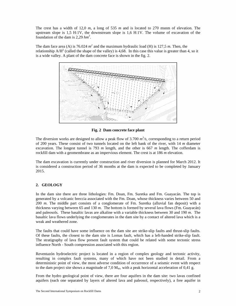
The crest has a width of 12,0 m, a long of 535 m and is located to 270 msnm of elevation. The upstream slope is 1,5 H:1V, the downstream slope is 1,6 H:1V. The volume of excavation of the foundation of the dam is 2,29 hm3. The dam face area (A) is 76.024 m2 and the maximum hydraulic load (H) is 127,5 m. Then, the relationship A/H2 (called the shape of the valley) is 4,68. In this case this value is greater than 4, so it is a wide valley. A plant of the dam concrete face is shown in the fig. 2.
Fig. 2 Dam concrete face plant
The diversion works are designed to allow a peak flow of 3.700 m3/s, corresponding to a return period of 200 years. These consist of two tunnels located on the left bank of the river, with 14 m diameter excavation. The longest tunnel is 793 m length, and the other is 667 m length. The cofferdam is rockfill dam with a geomembrane as an impervious element. The crest is at 186 m elevation. The dam excavation is currently under construction and river diversion is planned for March 2012. It is considered a construction period of 36 months at the dam is expected to be completed by January 2015. 2. GEOLOGY In the dam site there are three lithologies: Fm. Doan, Fm. Suretka and Fm. Guayacán. The top is generated by a volcanic breccia associated with the Fm. Doan, whose thickness varies between 50 and 200 m. The middle part consists of a conglomerate of Fm. Suretka (alluvial fan deposit) with a thickness varying between 65 and 130 m. The bottom is formed by several lava flows (Fm. Guayacán) and paleosols. These basaltic lavas are alkaline with a variable thickness between 30 and 190 m. The basaltic lava flows underlying the conglomerates in the dam site by a contact of altered lava which is a weak and weathered zone. The faults that could have some influence on the dam site are strike-slip faults and thrust-slip faults. Of these faults, the closest to the dam site is Lomas fault, which has a left-handed strike-slip fault. The stratigraphy of lava flow present fault system that could be related with some tectonic stress influence North - South compression associated with this region. Reventazón hydroelectric project is located in a region of complex geology and tectonic activity, resulting in complex fault systems, many of which have not been studied in detail. From a deterministic point of view, the most adverse condition of occurrence of a seismic event with respect to the dam project site shows a magnitude of 7,0 MW, with a peak horizontal acceleration of 0,41 g.
From the hydro geological point of view, there are four aquifers in the dam site: two lavas confined aquifers (each one separated by layers of altered lava and paleosol, respectively), a free aquifer in
The Second International Symposium on Rockfill Dams 3
conglomerate, and an aquifer hung in breccias. The aquifers of the dam site are continental, formed in volcanic and sedimentary fractured materials.
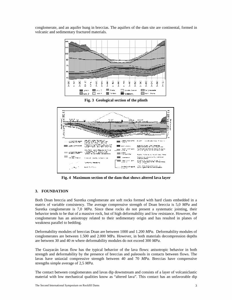
Fig. 3 Geological section of the plinth
Fig. 4 Maximum section of the dam that shows altered lava layer
3. FOUNDATION Both Doan breccia and Suretka conglomerate are soft rocks formed with hard clasts embedded in a matrix of variable consistency. The average compressive strength of Doan breccia is 5,0 MPa and Suretka conglomerate is 7,0 MPa. Since these rocks do not present a systematic jointing, their behavior tends to be that of a massive rock, but of high deformability and low resistance. However, the conglomerate has an anisotropy related to their sedimentary origin and has resulted in planes of weakness parallel to bedding. Deformability modules of breccias Doan are between 1000 and 1.200 MPa. Deformability modules of conglomerates are between 1.500 and 2.000 MPa. However, in both materials decompression depths are between 30 and 40 m where deformability modules do not exceed 300 MPa. The Guayacán lavas flow has the typical behavior of the lava flows: anisotropic behavior in both strength and deformability by the presence of breccias and paleosols in contacts between flows. The lavas have uniaxial compressive strength between 40 and 70 MPa. Breccias have compressive strengths simple average of 2,5 MPa. The contact between conglomerates and lavas dip downstream and consists of a layer of volcaniclastic material with low mechanical qualities know as “altered lava”. This contact has an unfavorable dip
The Second International Symposium on Rockfill Dams 4
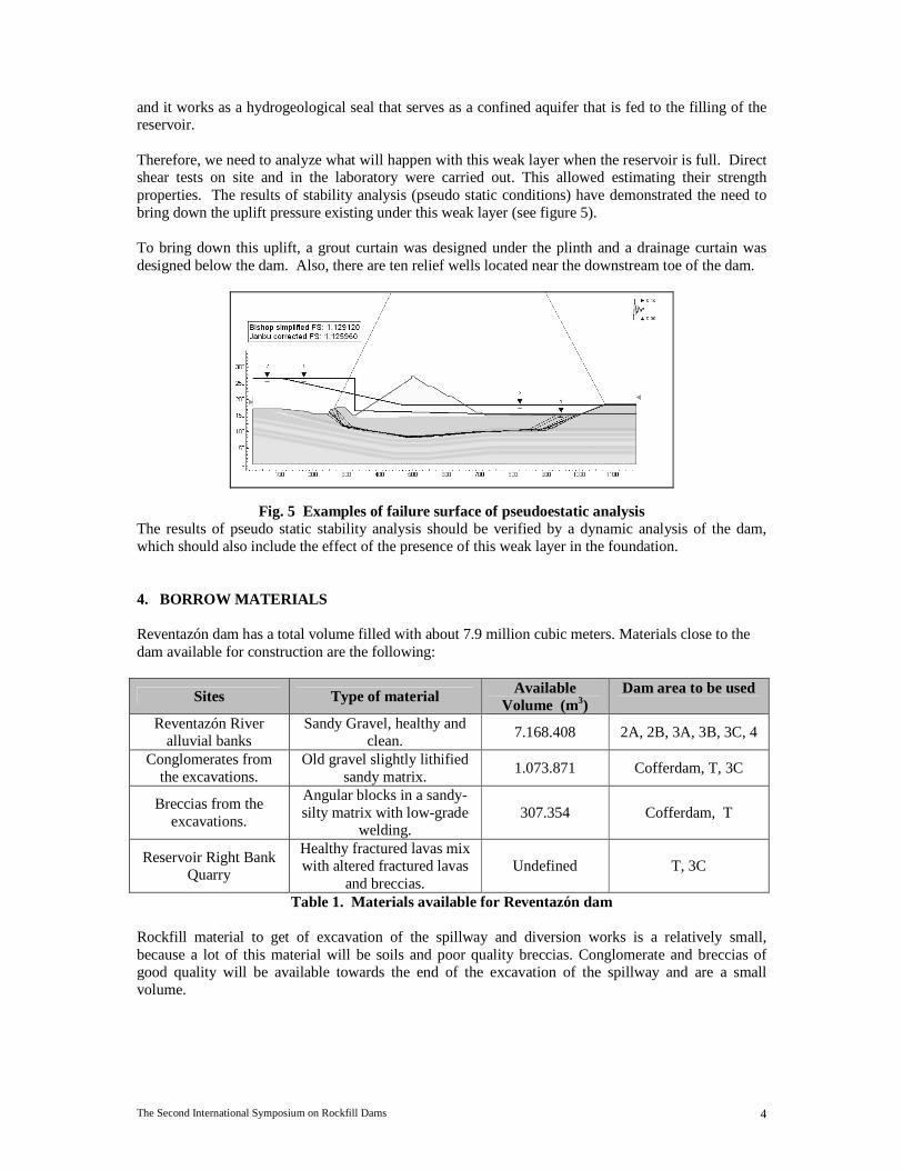
and it works as a hydrogeological seal that serves as a confined aquifer that is fed to the filling of the reservoir. Therefore, we need to analyze what will happen with this weak layer when the reservoir is full. Direct shear tests on site and in the laboratory were carried out. This allowed estimating their strength properties. The results of stability analysis (pseudo static conditions) have demonstrated the need to bring down the uplift pressure existing under this weak layer (see figure 5). To bring down this uplift, a grout curtain was designed under the plinth and a drainage curtain was designed below the dam. Also, there are ten relief wells located near the downstream toe of the dam.
Fig. 5 Examples of failure surface of pseudoestatic analysis The results of pseudo static stability analysis should be verified by a dynamic analysis of the dam, which should also include the effect of the presence of this weak layer in the foundation. 4. BORROW MATERIALS Reventazón dam has a total volume filled with about 7.9 million cubic meters. Materials close to the dam available for construction are the following:
Sites Type of material Available Volume (m3)
Dam area to be used
Reventazón River alluvial banks
Sandy Gravel, healthy and clean.
7.168.408 2A, 2B, 3A, 3B, 3C, 4
Conglomerates from the excavations.
Old gravel slightly lithified sandy matrix.
1.073.871 Cofferdam, T, 3C
Breccias from the excavations.
Angular blocks in a sandy-silty matrix with low-grade
welding. 307.354 Cofferdam, T
Reservoir Right Bank Quarry
Healthy fractured lavas mix with altered fractured lavas
and breccias. Undefined T, 3C
Table 1. Materials available for Reventazón dam Rockfill material to get of excavation of the spillway and diversion works is a relatively small, because a lot of this material will be soils and poor quality breccias. Conglomerate and breccias of good quality will be available towards the end of the excavation of the spillway and are a small volume.
The Second International Symposium on Rockfill Dams 5
5. PLINTH GEOTECHNICAL DESIGN The geotechnical design of the plinth was performed according to the criterion of internal plinth where the plinth width requirements are met in part by extending downstream of the plinth, under the upstream slope of the dam. The width of the plinth is dimensioned according to the terms of erodibility of the rock mass on which will be founded (ICOLD, 2004). The part of the plinth upstream of the perimeter joint was designed with a width of 4,5 m to facilitate the work of the foundation grouting. Boreholes give little information on the erodibility and the geophysics could not be performed because the topography is very steep. For the final design, it was expected to have additional drilling information and information from a seismic refraction to get a better characterization the different areas on which the plinth would be founded.
Materials in contact with the foundation of the plinth are shown in the figure 3 and are the following: • On the left side: above 207 m elevation breccia appears healthy, and below 207 m elevation
conglomerate appears healthy. • On the river: at 140 m level shows healthy conglomerate • On the right side: above 251 m elevation breccia appears healthy, and below 251 m elevation
conglomerate appears healthy. Both materials in healthy condition show a P wave speed of 1.600 to 1.900 m/s. That is, the mechanical properties of both materials are similar.
Seg
men
t
Seg
men
t E
leva
tions
H
ydra
ulic
Lo
ad H
(m
) Foundation (ICOLD
2004)
Maximun acceptable gradientd
Width of the Plinth (m)
Minimun Total
Width (m)
External Width
(m)
Minimun Internal
Width (m)
Proposed Internal Width
(m) PI2-PI3
140 al 189
126 Moderately
Erodible 10 12,6 4,50 8,10 8,50
PI1A- PI2
189 al 227
77 Moderately
Erodible 10 7,7 4,50 3,20 3,50
PI1- PI1A
227 al 266
39 Erodible 6 6,5 4,50 2,00 2,00
PI3 al PD3
140 al 140
126 Moderately
Erodible 10 12,6 4,50 8,10 8,50
PD3-PD3A
140 al 185
126 Moderately
Erodible 10 12,6 4,50 8,10 8,50
PD3A-PD2
185 al 231,5
81 Moderately
Erodible 10 8,1 4,50 3,60 4,00
PD2-PD1
231,5 al 266
34,5 Erodible 6 5,75 4,50 1,25 2,00
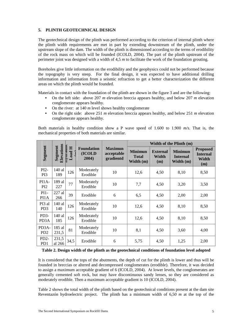
Table 2. Design width of the plinth as the geotechnical conditions of foundation level adopted It is considered that the tops of the abutments, the depth of cut for the plinth is lower and thus will be founded in breccias or altered and decompressed conglomerates (erodible). Therefore, it was decided to assign a maximum acceptable gradient of 6 (ICOLD, 2004). At lower levels, the conglomerates are generally cemented soft rock, but may have discontinuous sandy lenses, so they are considered as moderately erodible. Then a maximum acceptable gradient is 10 (ICOLD, 2004). Table 2 shows the total width of the plinth based on the geotechnical conditions present at the dam site Reventazón hydroelectric project. The plinth has a minimum width of 6,50 m at the top of the
The Second International Symposium on Rockfill Dams 6
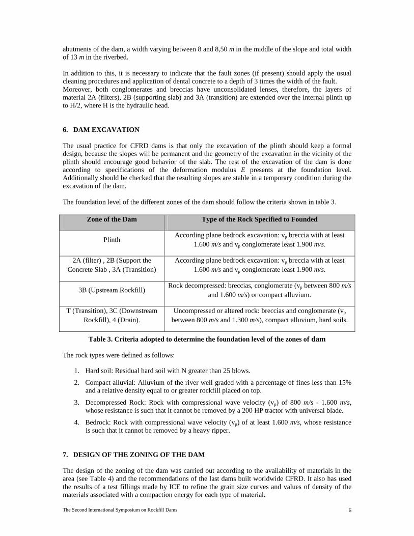
abutments of the dam, a width varying between 8 and 8,50 m in the middle of the slope and total width of 13 m in the riverbed. In addition to this, it is necessary to indicate that the fault zones (if present) should apply the usual cleaning procedures and application of dental concrete to a depth of 3 times the width of the fault. Moreover, both conglomerates and breccias have unconsolidated lenses, therefore, the layers of material 2A (filters), 2B (supporting slab) and 3A (transition) are extended over the internal plinth up to H/2, where H is the hydraulic head. 6. DAM EXCAVATION The usual practice for CFRD dams is that only the excavation of the plinth should keep a formal design, because the slopes will be permanent and the geometry of the excavation in the vicinity of the plinth should encourage good behavior of the slab. The rest of the excavation of the dam is done according to specifications of the deformation modulus E presents at the foundation level. Additionally should be checked that the resulting slopes are stable in a temporary condition during the excavation of the dam. The foundation level of the different zones of the dam should follow the criteria shown in table 3.
Zone of the Dam Type of the Rock Specified to Founded
Plinth According plane bedrock excavation: vp breccia with at least
1.600 m/s and vp conglomerate least 1.900 m/s.
2A (filter) , 2B (Support the Concrete Slab , 3A (Transition)
According plane bedrock excavation: vp breccia with at least 1.600 m/s and vp conglomerate least 1.900 m/s.
3B (Upstream Rockfill) Rock decompressed: breccias, conglomerate (vp between 800 m/s
and 1.600 m/s) or compact alluvium.
T (Transition), 3C (Downstream Rockfill), 4 (Drain).
Uncompressed or altered rock: breccias and conglomerate (vp between 800 m/s and 1.300 m/s), compact alluvium, hard soils.
Table 3. Criteria adopted to determine the foundation level of the zones of dam The rock types were defined as follows:
1. Hard soil: Residual hard soil with N greater than 25 blows.
2. Compact alluvial: Alluvium of the river well graded with a percentage of fines less than 15% and a relative density equal to or greater rockfill placed on top.
3. Decompressed Rock: Rock with compressional wave velocity (vp) of 800 m/s - 1.600 m/s, whose resistance is such that it cannot be removed by a 200 HP tractor with universal blade.
4. Bedrock: Rock with compressional wave velocity (vp) of at least 1.600 m/s, whose resistance is such that it cannot be removed by a heavy ripper.
7. DESIGN OF THE ZONING OF THE DAM The design of the zoning of the dam was carried out according to the availability of materials in the area (see Table 4) and the recommendations of the last dams built worldwide CFRD. It also has used the results of a test fillings made by ICE to refine the grain size curves and values of density of the materials associated with a compaction energy for each type of material.

The Second International Symposium on Rockfill Dams 7
Zone Function Description Origin Maximun
Size (mm)
Layer Thickness
(m)
1A Slab Protection Cohesionless Silty
Sand
Underground Excavation Works
conduction 2,5 0,25
1B 1A Zone
Protection and Containment
Fill Unselected Excavation Works 300 0,60
2A Perimeter Joint
Protection Fine Filter
Alluvial Deposits Processed
19 0,20
2B Support the
Concrete Slab Semi Permeable Filter
Alluvial Deposits Processed
100 0,30
3A Transition Zone between 2B and
3B Alluvial Graves Alluvial Deposits 250 0,30
3B Upstream Rockfill
Dam Axis Alluvial Graves Alluvial Deposits 550 0,60
T Transition Zone
downstream of the Dam Axis
Conglomerates, Alluvial with Breccia
Mixture or Lavas
Underground Excavation, Mixtures of Materials
550 0,60
3C Downstream
Rockfill Dam Axis Alluvial Graves or
Lavas Alluvial Deposits
or Lavas 700 0,80
4
Horizontal Drain
Alluvial Graves Alluvial Deposits 300
0,90
Vertical Drain or Chimney
0,40
Rip Rap Protection of
Downstream the slope face
Boulders, Lavas About Size from the River, Lavas
Blocks > 700 ---
Table 4. Description of materials to be used by landfill area of the dam For upstream areas (upstream the axis of dam) it will use alluvial materials obtained from the alluvial banks of the river Reventazón. For downstream areas it will use lower quality materials and mixtures of alluvial materials produced by the excavations. By using materials with higher fines content as conglomerates in the downstream area, it must enter a chimney drain in the dam. In the Figure 5 presents the maximum section of the dam. Below is the description and characteristics of each of the zones.

The Second International Symposium on Rockfill Dams 8
Fig. 5 Maximum cross section of the dam Zone 1A The zone 1A material is used as a protective element of the concrete face of the dam, located just above the slab. This zone consists of a cohesionless silty sand with a plasticity index between 5% and 7% to be obtained from the matrix of conglomerates from the excavations. This zone is located on the lower third of the face of concrete below the elevation 200 m and up to bed in the elevation 137 m. Zone 1B The zone 1B materials should be used to confine the area 1A. This material will not be selected. Be obtained from the excavation of the spillway, consider the breccias mainly. Zone 2A The 2A zone material should be used for the construction of the filter on the zone adjacent to the perimeter joint of the concrete face. Processed materials will be used, obtained from the crushing of relevant materials extracted from alluvial river terraces. The zone 2A should not have fines content greater than 10%, the gravel should be around 30% and sand content of approximately 65%. In the Figure 6 shows the grading band defined for this material. In addition, the materials for zone 2A should meet the requirements shown in Table 3.
Testing Requirement Absoption (ASTM C-127) 8% maximun
Abrasion Los Angeles Machine (ASTM C-535)
50% maximun after 1000 revolutions
Sodium sulfate soundness (ASTM C-88)
15% maximun after 5 cycles
Table 5. Additional requirements for the material of the Zone 2A of the dam filled Zone 2B The material in zone 2B should be used to build a semi-impermeable concrete face. A mixture of low permeability processed, from the best materials from the alluvial terraces that comply with the grading of Sherard (Sherard, 1987). This zone has a width of 4,0 m. This material must have between 35% and 55% of sand (passing the No. 4 sieve) and a maximum of 8% of silt or clay material passing the No. 200 sieve. With this
The Second International Symposium on Rockfill Dams 9
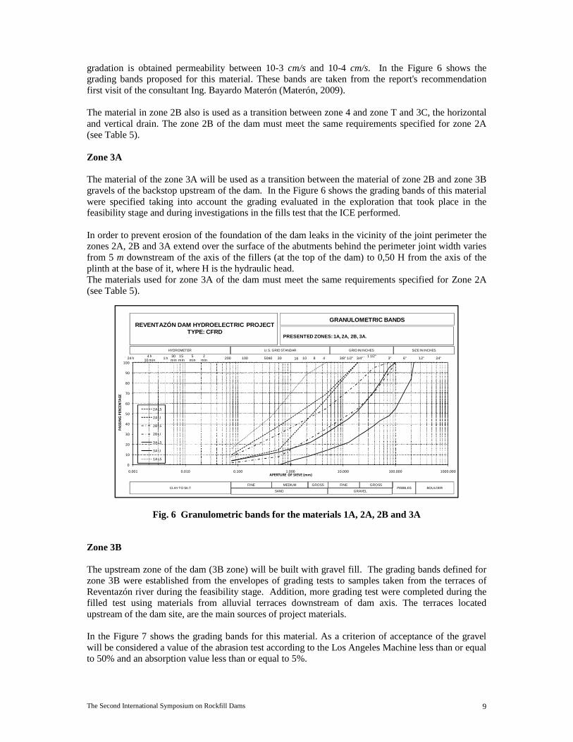
gradation is obtained permeability between 10-3 cm/s and 10-4 cm/s. In the Figure 6 shows the grading bands proposed for this material. These bands are taken from the report's recommendation first visit of the consultant Ing. Bayardo Materón (Materón, 2009). The material in zone 2B also is used as a transition between zone 4 and zone T and 3C, the horizontal and vertical drain. The zone 2B of the dam must meet the same requirements specified for zone 2A (see Table 5). Zone 3A The material of the zone 3A will be used as a transition between the material of zone 2B and zone 3B gravels of the backstop upstream of the dam. In the Figure 6 shows the grading bands of this material were specified taking into account the grading evaluated in the exploration that took place in the feasibility stage and during investigations in the fills test that the ICE performed. In order to prevent erosion of the foundation of the dam leaks in the vicinity of the joint perimeter the zones 2A, 2B and 3A extend over the surface of the abutments behind the perimeter joint width varies from 5 m downstream of the axis of the fillers (at the top of the dam) to 0,50 H from the axis of the plinth at the base of it, where H is the hydraulic head. The materials used for zone 3A of the dam must meet the same requirements specified for Zone 2A (see Table 5).
0
10
20
30
40
50
60
70
80
90
100
0.001 0.010 0.100 1.000 10.000 100.000 1000.000
PA
SS
ING
PE
RC
EN
TA
GE
APERTURE OF SIEVE (mm)
2A LS
2A LI
2B LS
2B LI
3A LS
3A LI
1A LS
PRESENTED ZONES: 1A, 2A, 2B, 3A.
GRANULOMETRIC BANDS
HYDROMETER U. S. GRID STANDAR GRID IN INCHES SIZE IN INCHES
CLAY TO SILTSAND
FINE MEDIUM GROSS
GRAVEL
FINE GROSSPEBBLES BOULDER
24"6"1 1/2" 3"13/4"1/2"3/8"2002min
5min
15min
30min1 h4 h
10 min 12"4104024 h 100 8163050
REVENTAZÓN DAM HYDROELECTRIC PROJECTTYPE: CFRD
Fig. 6 Granulometric bands for the materials 1A, 2A, 2B and 3A
Zone 3B The upstream zone of the dam (3B zone) will be built with gravel fill. The grading bands defined for zone 3B were established from the envelopes of grading tests to samples taken from the terraces of Reventazón river during the feasibility stage. Addition, more grading test were completed during the filled test using materials from alluvial terraces downstream of dam axis. The terraces located upstream of the dam site, are the main sources of project materials. In the Figure 7 shows the grading bands for this material. As a criterion of acceptance of the gravel will be considered a value of the abrasion test according to the Los Angeles Machine less than or equal to 50% and an absorption value less than or equal to 5%.
The Second International Symposium on Rockfill Dams 10
0
10
20
30
40
50
60
70
80
90
100
0.001 0.010 0.100 1.000 10.000 100.000 1000.000
PO
RC
EN
TA
JE P
AS
AN
DO
ABERTURA DE MALLA (mm)
3B LS
3B LI
Dren LS
Dren LI
T LS
T LI
3C LS
3C LI
PRESENTED ZONES: 3B, DRAINS T, 3C.
GRANULOMETRIC BANDS
HYDROMETER U. S. GRID STANDAR GRID IN INCHES SIZE IN INCHES
CLAY TO SILTSAND
FINE MEDIUM GROSS
GRAVEL
FINO GRUESOPEBBLES BOULDER
24"6"1 1/2" 3"13/4"1/2"3/8"2002min
5min
15min
30min1 h4 h
10 min 12"4104024 h 100 8163050
REVENTAZÓN DAM HYDROELECTRIC PROJECTTYPE: CFRD
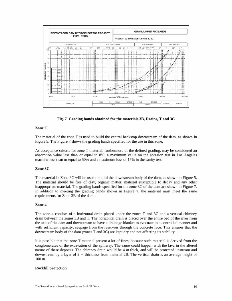
Fig. 7 Grading bands obtained for the materials 3B, Drains, T and 3C Zone T The material of the zone T is used to build the central backstop downstream of the dam, as shown in Figure 5. The Figure 7 shows the grading bands specified for the use in this zone. As acceptance criteria for zone T material, furthermore of the defined grading, may be considered an absorption value less than or equal to 8%, a maximum value on the abrasion test in Los Angeles machine less than or equal to 50% and a maximum loss of 15% in the sanity test. Zone 3C The material in Zone 3C will be used to build the downstream body of the dam, as shown in Figure 5. The material should be free of clay, organic matter, material susceptible to decay and any other inappropriate material. The grading bands specified for the zone 3C of the dam are shown in Figure 7. In addition to meeting the grading bands shown in Figure 7, the material must meet the same requirements for Zone 3B of the dam. Zone 4 The zone 4 consists of a horizontal drain placed under the zones T and 3C and a vertical chimney drain between the zones 3B and T. The horizontal drain is placed over the entire bed of the river from the axis of the dam and downstream to have a drainage blanket to evacuate in a controlled manner and with sufficient capacity, seepage from the reservoir through the concrete face. This ensures that the downstream body of the dam (zones T and 3C) are kept dry and not affecting its stability. It is possible that the zone T material present a lot of fines, because such material is derived from the conglomerates of the excavation of the spillway. The same could happen with the lava in the altered nature of these deposits. The chimney drain would be 4 m thick, and will be protected upstream and downstream by a layer of 2 m thickness from material 2B. The vertical drain is an average height of 100 m. Rockfill protection
The Second International Symposium on Rockfill Dams 11
The slope protection material downstream of the dam will be a rockfill layer consisting of fragments clean rock sizes from alluvial beaches, excavation of the spillway or underground excavations. Its size will be 0,70 m and the width of the buffer zone is 2 m measured horizontally. The quality of the rock fragments should ensure that there is no long-term decline. The following table shows the characteristics necessary for the placement and compaction of materials for each zone.
Zone Equipment Compaction
Number Past
1A Tractor D-8L or similar 2 1B Tractor D-8L or similar 2 2A Manual or Vibratory 10 Ton 4 2B Vibratory 15 Ton 4 3A Vibratory 15 Ton 4 3B Vibratory 15 Ton 4 3C Vibratory 15 Ton 6 T Vibratory 15 Ton 6
4 Chimney Drain
Tractor D-8L or similar 2
4 Horizontal Drain
Tractor D-8L or similar 2
Table 6. Characteristics of placement the zones of the dam 8. GEOMECHANICAL PROPERTIES OF THE MATERIALS OF THE DA M
8.1 Hydraulic Properties 8.1.1 Revision of the laws of filters between materials It is very important to check that compliance with the laws of filters on the materials placed downstream of the concrete face or to a chimney drain, because the filter system provides a second line of defense against leaks caused by cracks in the slab or perimeter joint failures. Moreover, the filter should be much more permeable than the interface sealant or material trapped on the perimeter joint. The following criteria condense the laws that material with basic filter function must meet (ICOLD, 2004).
1. Function of the internal erosion resistance given by the following relation (Marsal and Reséndiz, 1975):
D15F < 5* D85S
2. Function of permeability given by the following relationship (Marsal and Reséndiz, 1975): D15F ≥ 5* D15S
Where: D15: Size of the particles in the filter (protective agent) which constitute 15% by weight with a diameter less than that. d85: Size of the particles to protect which constitute the 85% by weight with a diameter less than that. d15: Size of the particles to protect which constitute the 15% by weight with a diameter less than that.
The Second International Symposium on Rockfill Dams 12
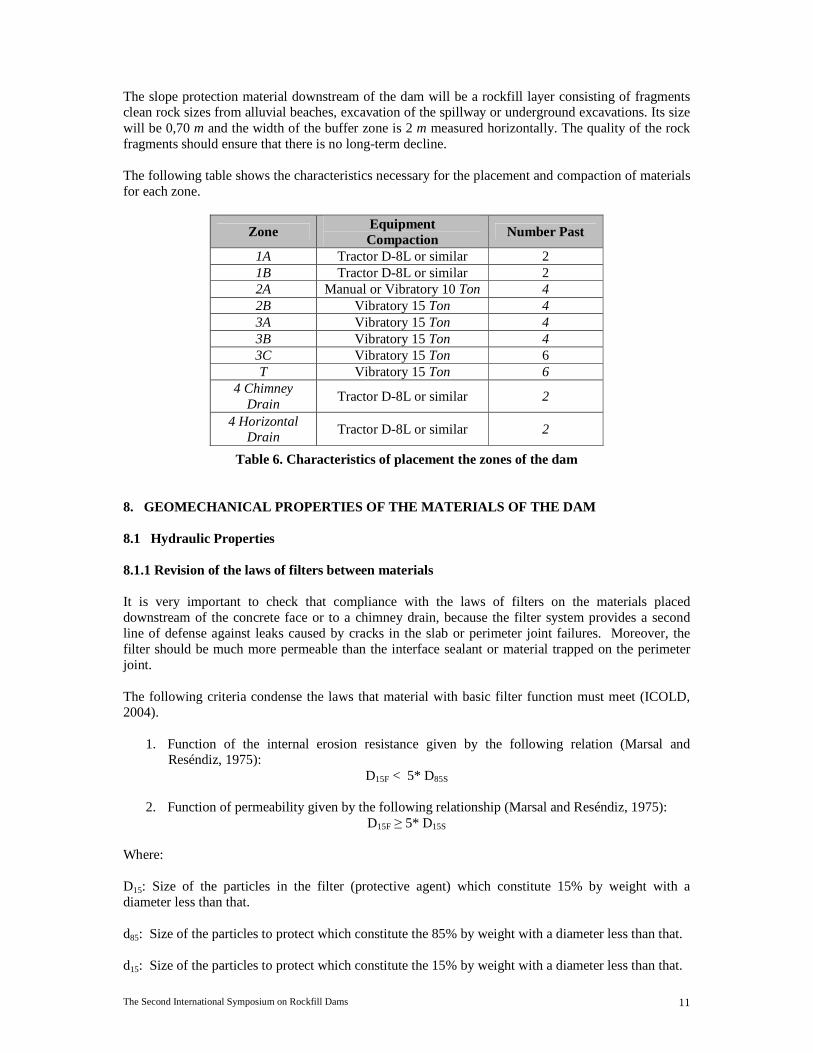
Compact Material D15F d15s d85S 5*d15s 5*d85S 1st Law of
Filters 2nd Law of
Filters 1A - 2A Average 0,19 0,08 1,82 0,38 9,10 Complies Not Comply 1A - 2B Average 0,34 0,08 1,82 0,38 9,10 Complies Not Comply 2A - 2B Average 0,33 0,19 10,07 0,95 50,35 Complies Not Comply 2B - 3A Average 2,30 0,33 45,00 1,65 225,00 Complies Complies 3A - 3B Average 8,40 2,30 150,00 11,50 750,00 Complies Not Comply 3B - 2B Average 0,33 8,25 320,00 41,25 1.600,00 Complies Not Comply
2B - Drain Average 40,00 0,33 45,00 1,65 225,00 Complies Complies T - 2B Average 0,33 3,20 377,78 16,00 1.888,90 Complies Not Comply
Table 7. Results from the application of the filter law of the materials According to criteria consulted, the first condition is the most important meet, especially among the materials 2B, 3A and 3B considering a high-permeability materials 3B (Yáñez, 2010). 8.1.2 Permeability of materials To estimate a permeability coefficient of materials (k), the Matsuo Akai test was performed on each materials valued in the execution of the test fill. The results are shown in the following summary table.
Material Origin k (cm/s)
2B Igneous 8,37E-04 3A Igneous 1,44E-03 3B Igneous 1,52E-02
Conglomerate Sedimentary 2,15E-03 Lavas Igneous 1,70E-03
3C Igneous >> 1,52E-02
Table 8. Values obtained for the permeability coefficient for each of the principal materials of the dam.
For the permeability of drains (zone 4) adopted a permeability of 1x10⁻¹ m/s, which is typical of a uniform clean gravel, since in these materials was not carried out any such test to check the value presented but given the behavior experienced by materials 3B and 3C is estimated that the permeability of the materials used as drains be higher in at least an order of magnitude. 8.2 Shear Strenght The methodology proposed by Barton and Kjaernsli (1981) allows for the variation of the effective friction angle of the gravel and rockfill in function of normal stress applied, taking into account the roughness of the particles, the compressive strength and the angle of friction materials of the particles that make up the rockfill. The equation involves obtaining both parameters proposed by Barton and Kjaernsli presented below (Barton and Kjaernsli, 1981).
Where you have to; Φ '= Effective friction angle of the rockfill.
The Second International Symposium on Rockfill Dams 13
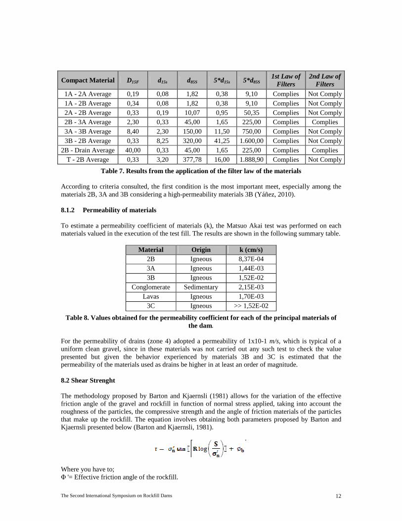
R = Equivalent roughness of the particles obtained according to the porosity and degree of roundness and softness of the particles. S = Equivalent resistance of the rockfill in the size of the particles d50 and uniaxial compressive strength of intact rock. σn = Effective normal stress. σb = Basic friction angle of the smooth, flat surfaces of the bedrock. Usually this value varies between 25 º and 35 º. For materials with gravel from alluvial beaches and indexed for each zone of the dam, as well as materials such conglomerates, lavas and breaches consolidated estimated parameters for the application of this methodology and are summarized in the table below.
Material Compressive
Strenght (Ton/m2)
d 50 e n Equivalent Roughness
R
Equivalent Resistance S
(Ton/m2) φb (°)
Conglomerate 9.447,05 40,37 0,13 11,42 4,16 6.801,57 30,00 Breccia 897,08 32,42 0,13 11,14 5,99 657,85 30,00 Lavas 6.906,60 58,00 0,17 14,57 4,47 4.834,62 35,00
2B 8.247,75 8,88 0,13 11,50 3,28 7.285,24 30,00 3A 8.247,75 48,64 0,05 4,99 3,35 5.841,88 30,00 3B 8.247,75 116,04 0,18 15,25 3,35 5.773,43 30,00 3C 8.247,75 70,00 0,17 14,57 3,26 5.773,43 30,00
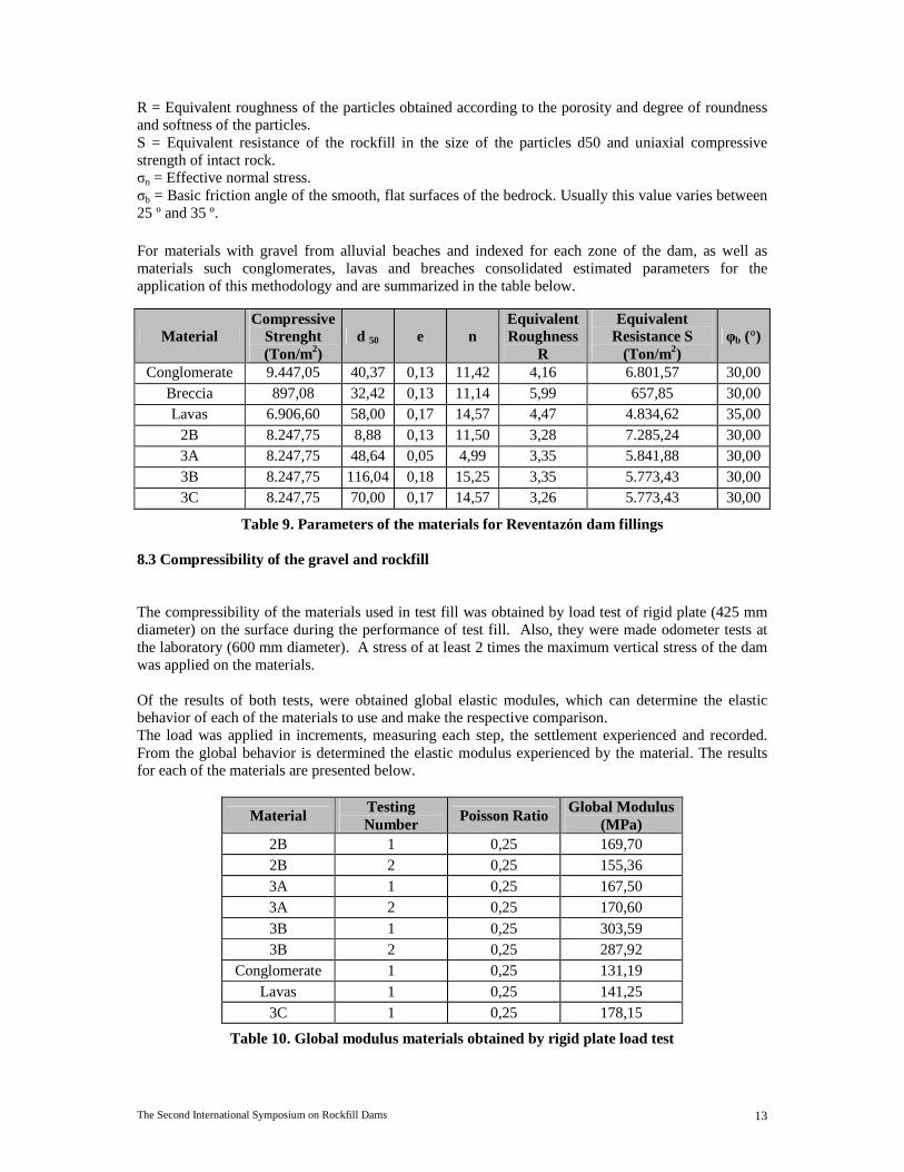
Table 9. Parameters of the materials for Reventazón dam fillings 8.3 Compressibility of the gravel and rockfill The compressibility of the materials used in test fill was obtained by load test of rigid plate (425 mm diameter) on the surface during the performance of test fill. Also, they were made odometer tests at the laboratory (600 mm diameter). A stress of at least 2 times the maximum vertical stress of the dam was applied on the materials. Of the results of both tests, were obtained global elastic modules, which can determine the elastic behavior of each of the materials to use and make the respective comparison. The load was applied in increments, measuring each step, the settlement experienced and recorded. From the global behavior is determined the elastic modulus experienced by the material. The results for each of the materials are presented below.
Material Testing Number
Poisson Ratio Global Modulus
(MPa) 2B 1 0,25 169,70 2B 2 0,25 155,36 3A 1 0,25 167,50 3A 2 0,25 170,60 3B 1 0,25 303,59 3B 2 0,25 287,92
Conglomerate 1 0,25 131,19 Lavas 1 0,25 141,25
3C 1 0,25 178,15
Table 10. Global modulus materials obtained by rigid plate load test

The Second International Symposium on Rockfill Dams 14
In the case of odometer testing procedure for obtaining the modulus is directly associated with volume changes experienced by a material under the action of forces (usually compressors) to which you want to submit the material; must be similar to those experienced on-site material placement within the filling of the dam. The results of the odometer test are shown in table 11.
Material Geological
Origin
Load Cycle (% Applied
Strain)
Obtained Deformation
(cm)
Applied Stress
(kg/cm2)
Obtained Odometer Modulus (MPa)
Breakage Grains (Bg)
2B Igneous 1 al 50% 0,33 23,87 383,76
30,16% 2 al 75% 0,61 35,80 311,37 3 al 100% 0,89 47,73 284,52
3A Igneous 1 al 50% 1,40 26,73 101,30
18,26% 2 al 75% 1,89 40,59 113,94 3 al 100% 2,37 54,45 121,89
3B Igneous 1 al 50% 1,09 25,74 125,29
2,76% 2 al 75% 1,67 39,60 125,80 3 al 100% 2,24 52,47 124,27
3C Igneous 1 al 50% 0,83 24,75 158,20
2,05% 2 al 75% 1,44 37,62 138,60 3 al 100% 2,04 50,49 131,31
Conglom. Sediment. 1 al 50% 5,75 22,77 21,01
5,00% 2 al 75% 6,50 33,66 27,47 3 al 100% 7,20 44,55 32,83
Lavas Igneous 1 al 50% 7,17 22,77 16,85
5,95% 2 al 75% 8,16 34,65 22,53 3 al 100% 8,76 46,53 28,18
Alluvial / Breccia
Igneous (Major Portion)
1 al 50% 2,91 24,75 45,12 3,67% 2 al 75% 3,73 36,63 52,10
3 al 100% 4,45 49,50 59,09
Table 11. Odometer module obtained for each of the materials used This test was performed within a steel cylinder, providing confinement to the material being subjected to only one-way stress. The trial includes three cycles of loading and unloading, showing a remaining deformation between each cycle which is cumulative and can determine the maximum deformation experienced by the materials, applying 100% of the determined stress. Obtaining samples for each material to evaluate the odometer test was subject to respecting a relationship between the diameter of the odometer and the nominal diameter of particles of 6, hence the set maximum size to be tested within odometer a nominal maximum size of 3" (75 mm). As this relationship between the diameter of the odometer and maximum particle size is larger, more representative results become. Obtaining the particle size for each of the materials to evaluate within the odometer, was performed by obtaining the homothetic curves according to the average grading envelopes for each of the materials obtained. Homothetic curves of the materials are obtained when the coefficient of uniformity and curvature of the original grading is identical to those obtained in the parallel gradation produced. 9. FILLS TEST The most important results were obtained for the materials tested during the fill test.
The Second International Symposium on Rockfill Dams 15
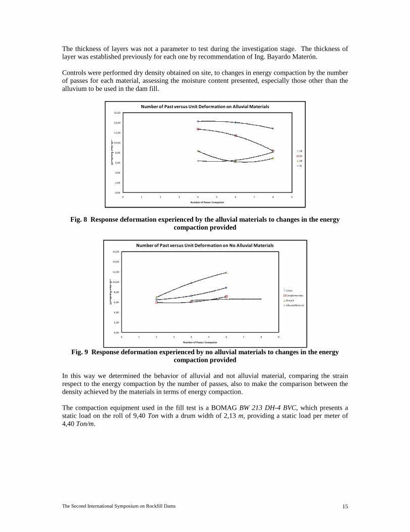
The thickness of layers was not a parameter to test during the investigation stage. The thickness of layer was established previously for each one by recommendation of Ing. Bayardo Materón. Controls were performed dry density obtained on site, to changes in energy compaction by the number of passes for each material, assessing the moisture content presented, especially those other than the alluvium to be used in the dam fill.
0,00
2,00
4,00
6,00
8,00
10,00
12,00
14,00
16,00
0 1 2 3 4 5 6 7 8 9
Unit Deformation (%)
Number of Passes Compactor
Number of Past versus Unit Deformation on Alluvial Materials
2B
3A
3B
3C
Fig. 8 Response deformation experienced by the alluvial materials to changes in the energy compaction provided
0,00
2,00
4,00
6,00
8,00
10,00
12,00
14,00
16,00
0 1 2 3 4 5 6 7 8 9
Unit Deformation (%)
Number of Passes Compactor
Number of Past versus Unit Deformation on No Alluvial Materials
Lavas
Conglomerates
Breach
Alluvial/Breccia
Fig. 9 Response deformation experienced by no alluvial materials to changes in the energy compaction provided
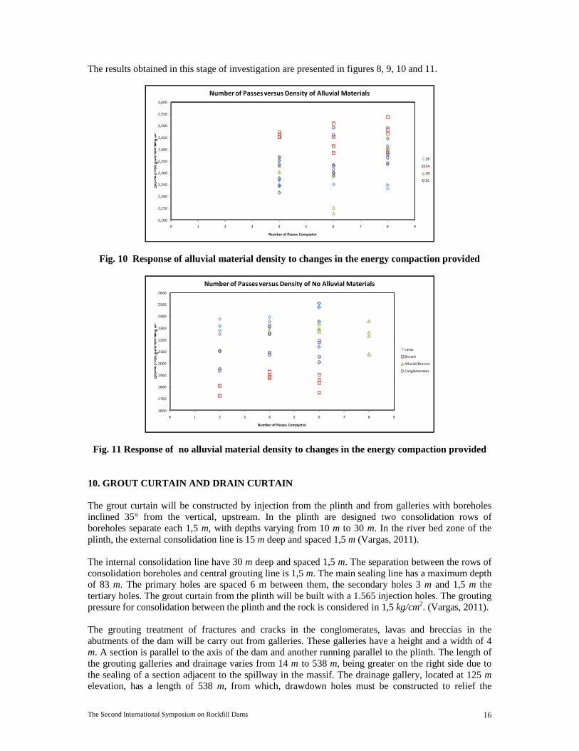
In this way we determined the behavior of alluvial and not alluvial material, comparing the strain respect to the energy compaction by the number of passes, also to make the comparison between the density achieved by the materials in terms of energy compaction. The compaction equipment used in the fill test is a BOMAG BW 213 DH-4 BVC, which presents a static load on the roll of 9,40 Ton with a drum width of 2,13 m, providing a static load per meter of 4,40 Ton/m.
The Second International Symposium on Rockfill Dams 16
The results obtained in this stage of investigation are presented in figures 8, 9, 10 and 11.
2,100
2,150
2,200
2,250
2,300
2,350
2,400
2,450
2,500
2,550
2,600
0 1 2 3 4 5 6 7 8 9
Density of the Materials (kg/m3)
Number of Passes Compactor
Number of Passes versus Density of Alluvial Materials
2B
3A
3B
3C
Fig. 10 Response of alluvial material density to changes in the energy compaction provided
1600
1700
1800
1900
2000
2100
2200
2300
2400
2500
2600
0 1 2 3 4 5 6 7 8 9
Density of the Materials (kg/m3)
Number of Passes Compactor
Number of Passes versus Density of No Alluvial Materials
Lavas
Breach
Alluvial/Breccia
Conglomerates
Fig. 11 Response of no alluvial material density to changes in the energy compaction provided
10. GROUT CURTAIN AND DRAIN CURTAIN The grout curtain will be constructed by injection from the plinth and from galleries with boreholes inclined 35° from the vertical, upstream. In the plinth are designed two consolidation rows of boreholes separate each 1,5 m, with depths varying from 10 m to 30 m. In the river bed zone of the plinth, the external consolidation line is 15 m deep and spaced 1,5 m (Vargas, 2011). The internal consolidation line have 30 m deep and spaced 1,5 m. The separation between the rows of consolidation boreholes and central grouting line is 1,5 m. The main sealing line has a maximum depth of 83 m. The primary holes are spaced 6 m between them, the secondary holes 3 m and 1,5 m the tertiary holes. The grout curtain from the plinth will be built with a 1.565 injection holes. The grouting pressure for consolidation between the plinth and the rock is considered in 1,5 kg/cm2. (Vargas, 2011). The grouting treatment of fractures and cracks in the conglomerates, lavas and breccias in the abutments of the dam will be carry out from galleries. These galleries have a height and a width of 4 m. A section is parallel to the axis of the dam and another running parallel to the plinth. The length of the grouting galleries and drainage varies from 14 m to 538 m, being greater on the right side due to the sealing of a section adjacent to the spillway in the massif. The drainage gallery, located at 125 m elevation, has a length of 538 m, from which, drawdown holes must be constructed to relief the

The Second International Symposium on Rockfill Dams 17
confined groundwater pressure of the confined aquifers lavas 1 and 2 (see Figure 3); allows deletions through drainage holes to cut the confined aquifer (Vargas, 2011). These vertical mini relief wells have a depth of 72 m on average, and will be constructed with slotted plastic tube. The slotted section is placed on the geological section that extends from the base of the altered lava until the roof of the Tobita (Vargas, 2011). The separation of the galleries is about 40 m placed in a vertical plane. The grouting holes are divided into drilling down at an angle of 35 ° respect to the vertical and a fan of boreholes with a length of 12 m and 15 m to intersect the holes from the upper gallery. In addition, the galleries will serve for the construction of drainage holes with a downstream direction with an angle of 20 ° with respect to the vertical and have a depth of 30 m whose function will collect the water that seeps through the grout curtain. The length of the grout curtain on both sides was calculated using the criteria of the critic hydraulic gradient for the conglomerate in regular condition, estimated with a value of 3, the location of the diversion tunnels, the background discharge and the spillway (Vargas, 2011). The 77,5% of the injection perforations will be held in the galleries and the remaining 22,5% in the plinth. In relation with these values shows that 74,3% of the length drilled for injection is for drilling in the galleries and occur the largest cement consumption (Vargas, 2011).
Fig. 12 Detail of the grout curtain
11. INSTRUMENTATION The dam will have three instrumented sections with the following instruments: 50 vibrating wire piezometers in the foundation, 41 vibrating wire settlement cells, 33 total pressure cells, 8 cross arm type USBR, 5 accelerographs. The concrete face will be instrumented with: 8 embedment strain gauges with 3 sensor each one 12 1D jointmeters 10 3D jointmeters 29 tiltmeters Reading most of these instruments will be automated using an automated data acquisition.

The Second International Symposium on Rockfill Dams 18
The aquifer under the weak layer is monitored by some of these piezometers and several additional open piezometers. 12. CONCLUSIONS Reventazón dam is a CFRD dam design according the modern concepts latest concepts in technical information and recommendations of international consultants in this type of dam. For the construction of the dam with alluvial materials that compacted in thin layers and with careful monitoring will result in very small settlements. This could be verified with the results of test fillings made. Two things make different the design of the dam:
• The presence of a weak layer below the dam also serves as a seal layer of an aquifer connected to the reservoir. For this, it was designed a drain curtain and relief wells.
• The high seismicity of the area. For this, lower angles were used in the slopes, crest width is bigger and zone 3B was extended to the downstream slope in the upper part of the dam. A dynamic analysis of the dam is beginning.
REFERENCES Barton, N., y Kjaernsli, B. 1981. Shear strength of Rockfill. Journal of the geotechnical engineering division. ASCE.107, 873-891.
Cruz, P., Materón, B., y Freitas, M. (2009). Concrete Face Rockfill Dams. Sao Paulo. Brasil.
ICOLD. (1994). Concrete Face Rockfill Dams Concepts for Design and Construction. Committee on Materials for Fill Dams.
Marsal, R, y Resendiz, D. 1975. Presas de Tierra y Enrocamiento. México; Editorial LIMUSA 221:267 p.
Materón, B. (2009). Informe correspondiente a la primera visita al Proyecto Hidroeléctrico Reventazón. Informe Técnico, 9-41.
Materón, B. (2010). Informe correspondiente a la segunda visita al Proyecto Hidroeléctrico Reventazón. Informe Técnico, 6-26.
Materón, B. 2009. Consultas técnicas referentes a resultados obtenidos para el módulo de deformabilidad de los materiales. San José. Comunicación personal.
Sherard, J., y Cooke, J.1987. Concrete Face of Dams: 1.Assessment. Geotechnique. ASCE. 113(10), 1096-1112.
Vargas, S. 2011. Consultas técnicas referentes al diseño de la cortina de inyección. Siquirres, Limón. Comunicación personal.
Yañez, D. 2010. Ley de filtros entre materiales de una cortina de enrocamiento. Sociedad Mexicana de Ingeniería Geotécnica, México.