cfd modeling for helium releases in a private garage without forced ventilation papanikolaou e. a....
Post on 19-Dec-2015
216 views
TRANSCRIPT
CFD Modeling for Helium Releases in a Private Garage without Forced Ventilation
Papanikolaou E. A.
Venetsanos A. G.
NCSR "DEMOKRITOS"
Institute of Nuclear Technology & Radiation Protection
Environmental Research Laboratory
Athens, GREECE
NCSR "DEMOKRITOS"INSTITUTE OF NUCLEAR TECHNOLOGY & RADIATION PROTECTIONENVIRONMENTAL RESEARCH LABORATORY

Summary
Scope: Evaluation of CFD ADREA-HF code capability to assess possible hazards posed by H2 releases in confined spaces
Experimental description Methodology
Computational domain and grid Mathematical formulation Initial and boundary conditions
Details of numerical solution Results of simulations Conclusions Future plans
NCSR "DEMOKRITOS" INSTITUTE OF NUCLEAR TECHNOLOGY & RADIATION PROTECTION ENVIRONMENTAL RESEARCH LABORATORY

Scope
NCSR "DEMOKRITOS" INSTITUTE OF NUCLEAR TECHNOLOGY & RADIATION PROTECTION ENVIRONMENTAL RESEARCH LABORATORY
Safe future H2 based society
Safe use or storage of H2 systems
inside buildings
CFD models for assessment of
hazards by H2 releases in confined spaces

Scope
NCSR "DEMOKRITOS" INSTITUTE OF NUCLEAR TECHNOLOGY & RADIATION PROTECTION ENVIRONMENTAL RESEARCH LABORATORY
Evaluation of CFD ADREA-HF code capability to assess such scenarios

Experimental Description Swain et.al. (1998)
Single car garage and sensors location
NCSR "DEMOKRITOS" INSTITUTE OF NUCLEAR TECHNOLOGY & RADIATION PROTECTION ENVIRONMENTAL RESEARCH LABORATORY
Vehicle and leak location 7.200 Lt/hr Helium for 2 hours

Experimental Description Swain et.al. (1998)
NCSR "DEMOKRITOS" INSTITUTE OF NUCLEAR TECHNOLOGY & RADIATION PROTECTION ENVIRONMENTAL RESEARCH LABORATORY
Case 1: 2.5 inches (6.35 cm) top and bottom door vents
Single car garage and sensors location
Vehicle and leak location 7.200 Lt/hr Helium for 2 hours

Experimental Description Swain et.al. (1998)
NCSR "DEMOKRITOS" INSTITUTE OF NUCLEAR TECHNOLOGY & RADIATION PROTECTION ENVIRONMENTAL RESEARCH LABORATORY
Case 2: 9.5 inches (24.13 cm) top and bottom door vents
Single car garage and sensors location
Vehicle and leak location 7.200 Lt/hr Helium for 2 hours

Experimental Description Swain et.al. (1998)
NCSR "DEMOKRITOS" INSTITUTE OF NUCLEAR TECHNOLOGY & RADIATION PROTECTION ENVIRONMENTAL RESEARCH LABORATORY
Case 3: 19.5 inches (24.13 cm) top and bottom door vents
Single car garage and sensors location
Vehicle and leak location 7.200 Lt/hr Helium for 2 hours

MethodologyI. Computational Domain & Grid
Domain extends beyond garage boundary
NCSR "DEMOKRITOS" INSTITUTE OF NUCLEAR TECHNOLOGY & RADIATION PROTECTION ENVIRONMENTAL RESEARCH LABORATORY
Assumption of x-z plane symmetry due to geometry of facility and location of leak

MethodologyI. Computational Domain & Grid
NCSR "DEMOKRITOS" INSTITUTE OF NUCLEAR TECHNOLOGY & RADIATION PROTECTION ENVIRONMENTAL RESEARCH LABORATORY
Sensors located at the same side given the symmetry assumption
Domain extends beyond garage boundary

MethodologyI. Computational Domain & Grid
3-D Cartesian grid Grid refinement close to vents,
source, walls Max. grid expansion ratio: 1.2 Min. grid expansion ratio: 0.84 Classification of cells into fully
active, inactive and partially active DELTA_B Code for geometrical pre-
processing
NCSR "DEMOKRITOS" INSTITUTE OF NUCLEAR TECHNOLOGY & RADIATION PROTECTION ENVIRONMENTAL RESEARCH LABORATORY
Grid characteristics Case 1 Case 2 Case 3
Grid dimensions 882648 882650 882644
Number of active cells 101.887 106.218 93.552
Min. and Max. cell size in z-direction (m)
0.04 close to source0.512 at domain’s top
0.038 close to source0.513 at domain’s top
0.065 close to source0.516 at domain’s top
Min. and Max. cell size in x-direction (m)
0.02 close to door0.92 at domain’s end
Minimum and Maximum cell size in y-direction (m)
0.1 close to source and symmetry plane0.401 at domain’s beginning

MethodologyII. Mathematical Formulation
3-D transient, fully compressible conservation equations Mixture mass
Mixture momentum
Helium mass fraction
Mixture density and mass fractions and
Component densities through ideal gas law
0
i
i
x
u
t
NCSR "DEMOKRITOS" INSTITUTE OF NUCLEAR TECHNOLOGY & RADIATION PROTECTION ENVIRONMENTAL RESEARCH LABORATORY
i
j
j
it
ji
ij
iji
x
u
x
u
xg
x
P
x
uu
t
u
0.72 , m
106494.5d , 2
5-111
sx
qd
xx
qu
t
q
j
t
jj
j
2
2
1
11
TRP ii
211 qq

MethodologyII. Mathematical Formulation (continued)
Standard k-ε model for turbulence Turbulent viscosity Turbulent kinetic energy, k
Volumetric production rate of k by shear forces G and buoyancy production (destruction) term GB
Dissipation rate of turbulent kinetic energy, ε
09.0C ,2
k
Ct
NCSR "DEMOKRITOS" INSTITUTE OF NUCLEAR TECHNOLOGY & RADIATION PROTECTION ENVIRONMENTAL RESEARCH LABORATORY
0.1 , k
Bjk
t
jj
jGG
x
k
xx
ku
t
k
z
g-G and z
tB
j
i
i
j
j
it x
u
x
u
x
uG
1.0 and 1.92 1.44, 1.3,
,
321
231
CCC
CGCGCkxxx
u
t Bj
t
jj
j

MethodologyII. Mathematical Formulation (continued)
NCSR "DEMOKRITOS" INSTITUTE OF NUCLEAR TECHNOLOGY & RADIATION PROTECTION ENVIRONMENTAL RESEARCH LABORATORY
Variables to be calculated Component velocities u, v, w He mass fraction, q1
Pressure, P Turbulent kinetic energy, k Dissipation rate of turbulent kinetic energy, ε
Not calculated variable but supplied by the initialization data Temperature, T

MethodologyIII. Initial & Boundary Conditions
Initial Conditions Zero wind velocity with no turbulence Temperature of 293.15 K and hydrostatic
pressure Boundary Conditions applied to:
1 free building surface as the Helium source 28 solid building surfaces 1 solid domain surface (the ground) 5 free domain surfaces
NCSR "DEMOKRITOS" INSTITUTE OF NUCLEAR TECHNOLOGY & RADIATION PROTECTION ENVIRONMENTAL RESEARCH LABORATORY

MethodologyIII. Initial & Boundary Conditions (continued)
NCSR "DEMOKRITOS" INSTITUTE OF NUCLEAR TECHNOLOGY & RADIATION PROTECTION ENVIRONMENTAL RESEARCH LABORATORY
Variable Source
u
v
w
q1
k
ε
0
0
zu
u
0
0
zv
v
0
1.0
zw
w
0
1
1
1
zq
q
0
0
zk
k
0
0
z
Inflow boundary conditions at the source

MethodologyIII. Initial & Boundary Conditions (continued)
NCSR "DEMOKRITOS" INSTITUTE OF NUCLEAR TECHNOLOGY & RADIATION PROTECTION ENVIRONMENTAL RESEARCH LABORATORY
Wall function for velocity:
Wall function for k:
Wall function for ε:
212
Cuk
y
kC
43
43
6.11for y )9ln(1
6.11for y
y
yu
Variable
u Wall function
v Wall function
w Wall function
q1
k Wall function
ε Wall function
Solid building surfaces (28)
01
nq

MethodologyIII. Initial & Boundary Conditions (continued)
NCSR "DEMOKRITOS" INSTITUTE OF NUCLEAR TECHNOLOGY & RADIATION PROTECTION ENVIRONMENTAL RESEARCH LABORATORY
Wall function for velocity:
Wall function for k:
Wall function for ε:
212
Cuk
y
kC
43
43
6.11for y )9ln(1
6.11for y
y
yu
The wall function for velocity forms the basis of the empirical relationship to describe the shape of the wall boundary layer in non-dimensional terms
wall thefrom centre cell near wall of distance:y
wallfrom distance lizeddimensiona-Non
stressshear wall: , velocity Friction w
21
w
yuy
u
Variable
u Wall function
v Wall function
w Wall function
q1
k Wall function
ε Wall function
Solid building surfaces (28)
01
nq

MethodologyIII. Initial & Boundary Conditions (continued)
NCSR "DEMOKRITOS" INSTITUTE OF NUCLEAR TECHNOLOGY & RADIATION PROTECTION ENVIRONMENTAL RESEARCH LABORATORY
Wall function for velocity:
Wall function for k:
Wall function for ε:
212
Cuk
y
kC
43
43
6.11for y )9ln(1
6.11for y
y
yu
Variable
u Wall function
v Wall function
w Wall function
q1
k Wall function
ε Wall function
Solid domainsurface (ground)
01
nq

MethodologyIII. Initial & Boundary Conditions (continued)
NCSR "DEMOKRITOS" INSTITUTE OF NUCLEAR TECHNOLOGY & RADIATION PROTECTION ENVIRONMENTAL RESEARCH LABORATORY
Free domain
surface1
Variable West side
u
v *1
w *1
q1 *1
k *1
ε *1
0
xu
Free domain
surface2
Variable East side
u
v *1
w *1
q1 *1
k *1
ε *1
0
xu
Free domain
surface3
Variable South side
u *1
v
w *1
q1 *1
k *1
ε *1
0
yv
Free domain
surface4
VariableSymmetry
plane
u
v
w
q1
k
ε
0v
0
yu
0
yw
01
yq
0
yk
0
y
Free domain
surface5
Variable Top plane
u *1
v *1
w *2
q1 *1
k *1
ε *1
*1 function of the flow direction*2 normal velocity obtained from continuity equation
*1 function of the flow direction

Details of Numerical Solution
NCSR "DEMOKRITOS" INSTITUTE OF NUCLEAR TECHNOLOGY & RADIATION PROTECTION ENVIRONMENTAL RESEARCH LABORATORY
CFD Code ADREA-HF for simulation Control volume discretization method, staggered grid
arrangement for velocities First order fully implicit scheme for time integration First order upwind scheme for discretization of the
convective terms Automatic time step selection based on convergence error
Initial time step: 10-3 seconds Maximum permitted time step: 10-1 seconds
Intel® XeonTM CPU 3.60GHz with Windows operating system
Calculations performed for real time of 7.200 seconds

Results: Case 1 (2.5 inches)
Outputs of simulation versus experimental data at sensor locations
NCSR "DEMOKRITOS" INSTITUTE OF NUCLEAR TECHNOLOGY & RADIATION PROTECTION ENVIRONMENTAL RESEARCH LABORATORY
Good agreement for sensors 2 and 3 (upper vents)
Overestimation for sensors 1 and 4 (lower vents)
Underestimation of the predicted concentration difference between top and lower sensors

Results: Case 1 (continued)
Bottom vent provides a flow of fresh air, flowing under the vehicle Upper vent provides an exit of the low density gas mixture, near
the ceiling The combustible gas cloud is located under the vehicle, near the
source and extends in the z-direction in front of it The rest of the garage gas remained leaner than the lean limit of
combustion for Hydrogen Flow pattern has reached steady state conditions at least at 3.600
seconds
NCSR "DEMOKRITOS" INSTITUTE OF NUCLEAR TECHNOLOGY & RADIATION PROTECTION ENVIRONMENTAL RESEARCH LABORATORY

Results: Case 2 (9.5 inches)
Outputs of simulation versus experimental data at sensor locations
NCSR "DEMOKRITOS" INSTITUTE OF NUCLEAR TECHNOLOGY & RADIATION PROTECTION ENVIRONMENTAL RESEARCH LABORATORY
The vent sizes are almost 4 times broader than in Case 1
The predicted He concentrations are in satisfactory agreement with the experimental data for all sensors

Results: Case 2 (continued)
The exiting gas mixture has now a wider column-like shape which broadens with height
Most of the garage gas remained leaner than the lean limit of combustion for Hydrogen (4.1%)
Flow pattern has reached steady state conditions at least at 3.600 seconds
NCSR "DEMOKRITOS" INSTITUTE OF NUCLEAR TECHNOLOGY & RADIATION PROTECTION ENVIRONMENTAL RESEARCH LABORATORY

Results: Case 3 (19.5 inches)
Outputs of simulation versus experimental data at sensor locations
NCSR "DEMOKRITOS" INSTITUTE OF NUCLEAR TECHNOLOGY & RADIATION PROTECTION ENVIRONMENTAL RESEARCH LABORATORY
Underestimation for sensors 1, 2 and 3
Small over prediction for sensor 4
The predicted natural ventilation rate is overestimated

Results: Case 3 (continued)
The maximum Helium concentration is located at the source and occupies much less space
The column of the outflow gas is now much broader resulting in lower Helium concentrations inside the garage
Flow pattern has reached steady state conditions at least at 3.600 seconds
NCSR "DEMOKRITOS" INSTITUTE OF NUCLEAR TECHNOLOGY & RADIATION PROTECTION ENVIRONMENTAL RESEARCH LABORATORY

Conclusions
The ADREA-HF CFD code was successfully applied to simulate 3 full scale Helium release experiments
The predicted results were generally in acceptable agreement with the experimental data
The calculations revealed the mixing patterns Mixing mechanisms reached a near-equilibrium
state resulting in a constant cloud size and shape during the release period
CFD practice is important for evaluation of potential hazards especially under complex release conditions
NCSR "DEMOKRITOS" INSTITUTE OF NUCLEAR TECHNOLOGY & RADIATION PROTECTION ENVIRONMENTAL RESEARCH LABORATORY
Future Plans
Evaluation of the performance of other turbulence models under the same experimental conditions
Development of CFD practice guidelines for such kind of flows
NCSR "DEMOKRITOS" INSTITUTE OF NUCLEAR TECHNOLOGY & RADIATION PROTECTION ENVIRONMENTAL RESEARCH LABORATORY
Acknowledgements
NCSR "DEMOKRITOS" INSTITUTE OF NUCLEAR TECHNOLOGY & RADIATION PROTECTION ENVIRONMENTAL RESEARCH LABORATORY
The authors would like to thank the Greek
Secretariat of Research and Technology as well
as the European Commission for funding
for this work through the 02-PRAKSE-42 and HYSAFE-NoE projects
respectively

• NCSR "DEMOKRITOS"• INSTITUTE OF NUCLEAR TECHNOLOGY & RADIATION PROTECTION• ENVIRONMENTAL RESEARCH LABORATORY
Animation (Case 1)

• NCSR "DEMOKRITOS"• INSTITUTE OF NUCLEAR TECHNOLOGY & RADIATION PROTECTION• ENVIRONMENTAL RESEARCH LABORATORY
Animation (Case 1continued)

• NCSR "DEMOKRITOS"• INSTITUTE OF NUCLEAR TECHNOLOGY & RADIATION PROTECTION• ENVIRONMENTAL RESEARCH LABORATORY
Animation (Case 2)

• NCSR "DEMOKRITOS"• INSTITUTE OF NUCLEAR TECHNOLOGY & RADIATION PROTECTION• ENVIRONMENTAL RESEARCH LABORATORY
Animation (Case 2continued)

• NCSR "DEMOKRITOS"• INSTITUTE OF NUCLEAR TECHNOLOGY & RADIATION PROTECTION• ENVIRONMENTAL RESEARCH LABORATORY
Animation (Case 3)

• NCSR "DEMOKRITOS"• INSTITUTE OF NUCLEAR TECHNOLOGY & RADIATION PROTECTION• ENVIRONMENTAL RESEARCH LABORATORY
Animation (Case 3continued)
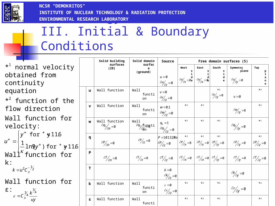
MethodologyIII. Initial & Boundary Conditions
*1 normal velocity obtained from continuity equation
*2 function of the flow directionWall function for velocity:
Wall function for k:
Wall function for ε:
212
Cuk
NCSR "DEMOKRITOS" INSTITUTE OF NUCLEAR TECHNOLOGY & RADIATION PROTECTION ENVIRONMENTAL RESEARCH LABORATORY
0
0
zu
u0
x
u0
xu 0
y
u
0
0
zv
v0
y
v0v
0
1.0
zw
w0
y
w
01
nq 01
z
q
0
1
1
1
zq
q01
y
q
0
nP 0
z
P0
101325
zP
PaP
0
xP0
x
P 0
yP0
y
P0
zP
0
nT 0
z
T0
zT 0
x
T0
xT 0
y
T0
yT0
z
T
0
0
zk
k0
y
k
0
0
z
0
y
y
kC
43
43
6.11for y )9ln(1
6.11for y
y
yu
Solid building surfaces
(28)
Solid domain surface
(ground)
Source Free domain surfaces (5)
West side East side South side Symmetry plane Top plane
u Wall function Wall function *2 *2
v Wall function Wall function *2 *2 *2
w Wall function Wall function *2 *2 *2 *1
q *2 *2 *2 *2
P
T
k Wall function Wall function *2 *2 *2 *2
ε Wall function Wall function *2 *2 *2 *2

Details of Numerical Solution
Required CPU time (in seconds) of three cases
649760.6
596784.02
543212.6
400000
500000
600000
700000
Case 1Case 2Case 3
NCSR "DEMOKRITOS" INSTITUTE OF NUCLEAR TECHNOLOGY & RADIATION PROTECTION ENVIRONMENTAL RESEARCH LABORATORY
Required time (in seconds) to reach maximum time step
2.771.809 1.25
0.0
2.0
4.0
6.0
8.0
10.0
Case 1Case 2Case 3

Relative error (%) of Cases 1, 2 and 3
NCSR "DEMOKRITOS" INSTITUTE OF NUCLEAR TECHNOLOGY & RADIATION PROTECTION ENVIRONMENTAL RESEARCH LABORATORY