cfd high lift calculations using usm3d - nasa · cfd high lift calculations using usm3d khaled s....
TRANSCRIPT

CFD High Lift Calculations Using USM3D
Khaled S. Abdol-Hamid
Mohagna Pandya
Ed Parlette
NASA Langley Research Center
1st AIAA CFD High Lift Prediction Workshop (HiLiftPW-1)
28th AIAA Applied Aerodynamics Conference
June 26-27 2010, Chicago, IL
Outline
• TetrUSS System
• Flow Condition and Cases
• Down select of Turbulence Model
• CD by Components
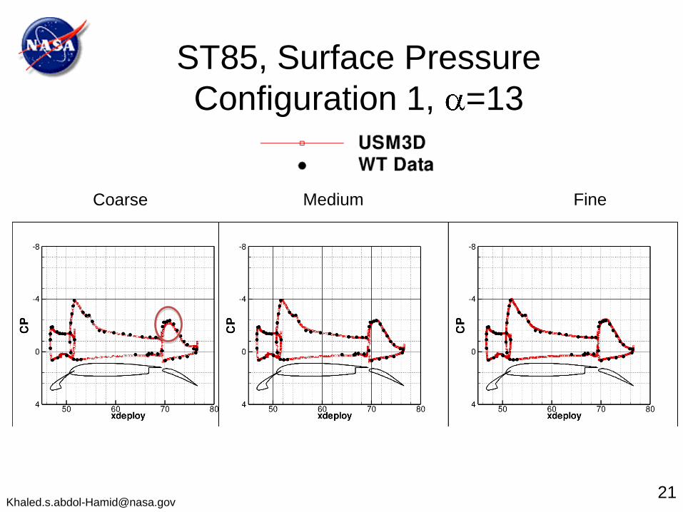
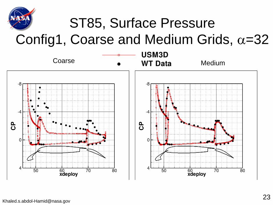
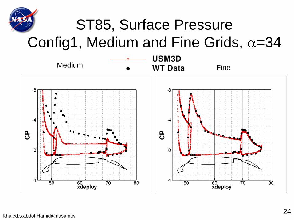
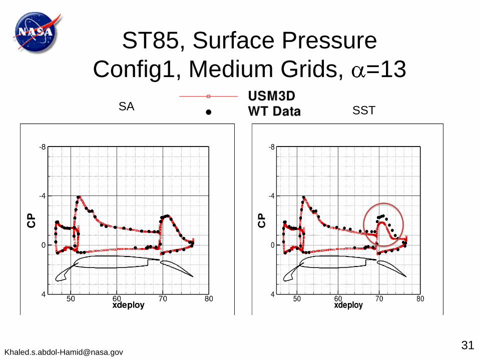
• Surface Pressure
• Sectional/Cumulative CL and CD
• Observations
2

TetrUSSTetrahedral Unstructured Software System
Grid Generation
VGRID OpenGL
Tools & UtilitiesFlow Solver
USM3D
Visualization
SimpleView
and
Commercial Packages
Geometry Setup
GridTool
TetrUSS is a loosely integrated, flexible aeroanalysis and design system that
• provides initial solutions to complex problems
within days
• provides accurate representation of flow physics
• heavily used in NASA and Industry projects
• continually improved to meet project needs
3

• Tetrahedral cell-centered, finite volume
– Single- and overset-grid
• Euler and Navier-Stokes
– Several 1- and 2-equation turbulence models
– SA and SST used for the present study
• Time Integration
– Steady-state w/ local time stepping
– 2nd order time accuracy
• Upwind spatial discretization
– FDS, AUSM, HLLC, LDFSS, FVS
– Min-mod and Venkat limiters
• Standard and special BC’s
• Parallelized for clusters
– SGI, Sun, PC/Linux, Alpha/Linux, Mac OS X, IBM, HP
– input/output files in global form
USM3D
Tetrahedral Flow Solver
B. D. Goble and J. R. Hooker
Lockheed Martin Aeronautics Company
NASA Apollo Launch Abort System
4

High Lift Cases
5
Geometry Turbulence Models Grids
Configuration 1 SA and SST Coarse, Medium and Fine
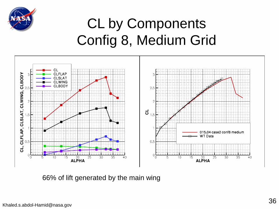
Configuration 8 SA Medium
Configuration 1 - Slat 30, Flap 25 full span
Configuration 8 - Slat 30, Flap 20 full span
M∞=0.2, T∞=520 °R, Rec=4.3x10⁶

Configuration 1 Grid Statistics
Coarse grid
Cells = 7.237,190
nfacs = 108,006
CPU = 96
WallTime= 2 hours
Medium grid
Cells = 21,743,354
nfacs = 278,590
CPU = 128
WallTime = 8 hours
Fine Grid
Cells= 62,644,381
nfacs = 668,822
CPU = 512
WallTime = 6 hours
Tet-Cellcentered-A-v1
Computer: Pleiades Harpertown nodes, Q1 2010
6
Y+ VariationsY+=1
Y+=2/3 Y+=4/9
Configuration 1 - Slat 30, Flap 25 full span


Grid Sensitivity of CL
SA and SST Models
9
SA Model CLmax
Coarse 30, Medium 32, Fine 34
SST Model CLmax
Coarse 28, Medium 28, Fine 32
Underpredicts CL For Alpha<28

Grid Sensitivity of CL
SA and SST Models
10
SA Model CLmax
Coarse 30, Medium 32, Fine 34
SST Model CLmax
Coarse 28, Medium 28, Fine 32
Underpredicts CL For Alpha<28


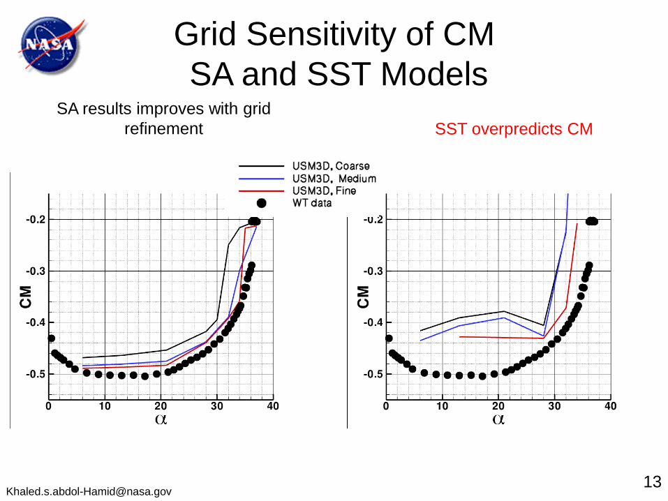
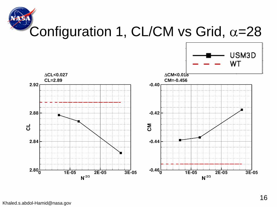
Grid Sensitivity of CM
SA and SST Models
13
SA results improves with grid
refinement SST overpredicts CM


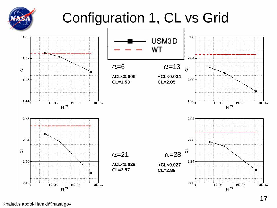
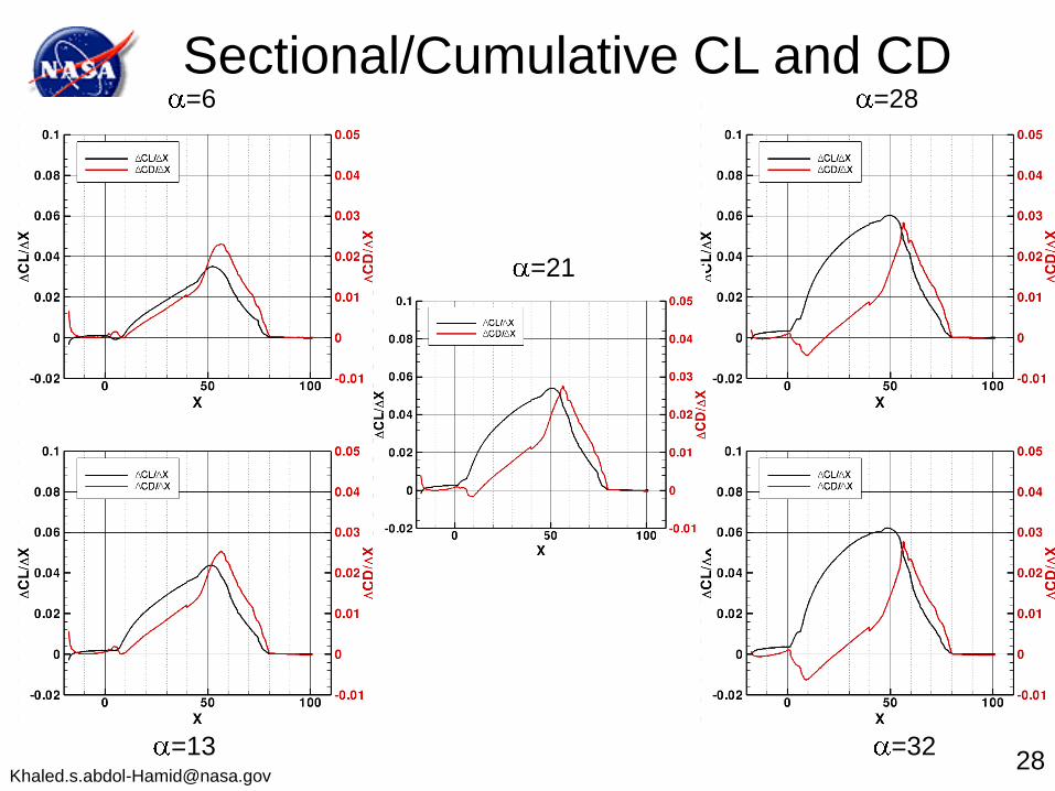
=21
=6 =13
=28
CL<0.006
CL=1.53
CL<0.034
CL=2.05
CL<0.029
CL=2.57CL<0.027
CL=2.89
Configuration 1, CL vs Grid

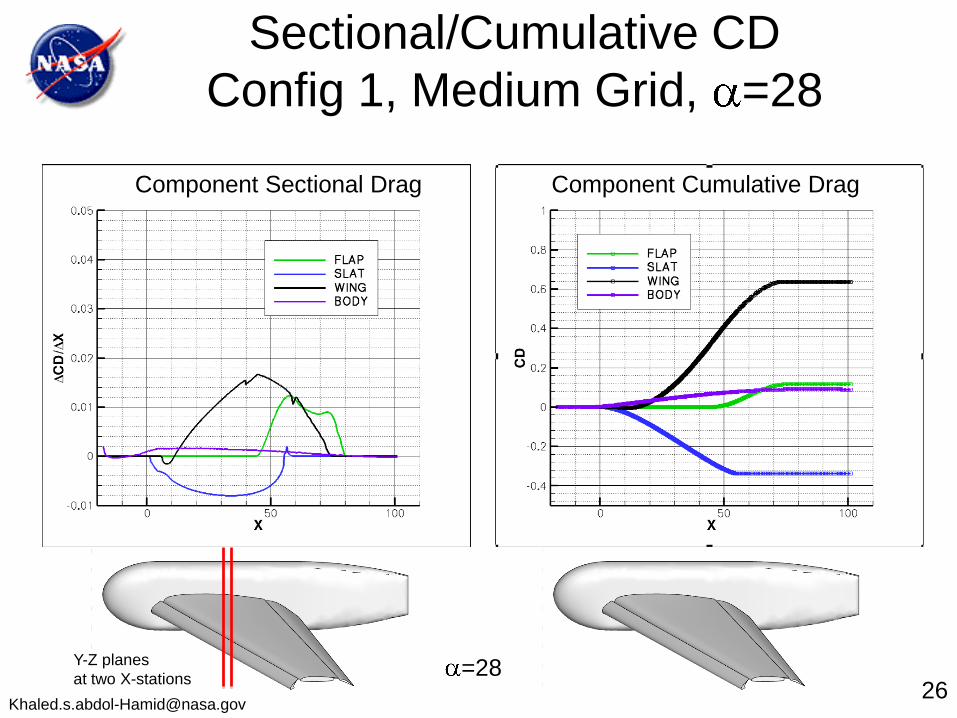
At =6, the flap generates 95% of the drag
For >13, the main wing generates most of the drag
The slat generates thrust (-ve Drag) for all s
CD by Components
Configuration 1
19


=28
Component Sectional Drag Component Cumulative Drag
Sectional/Cumulative CD
Config 1, Medium Grid, =28
Y-Z planes
at two X-stations26
=28
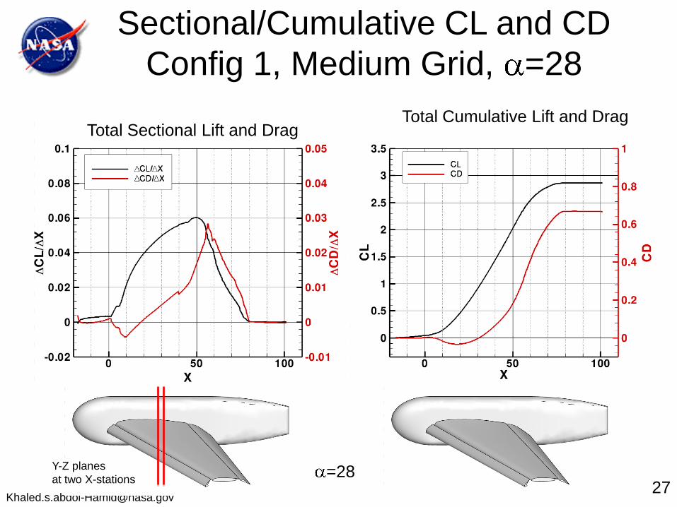
Total Sectional Lift and DragTotal Cumulative Lift and Drag
Sectional/Cumulative CL and CD
Config 1, Medium Grid, =28
Y-Z planes
at two X-stations27
Observations
• SST model underpredicts CL and overpredicts CM
• SA model produces generally better results than SST and was selected for the rest of the study
• With grid refinement, CLMAX and stall angle are much closer to experimental data
• Medium grid is sufficient to produce generally good results with less resources upto a stall angle of 32 degree
• Coarse grid produces good result upto 28 angle of attack and can be used for quick evaluation of the high lift configuration
29

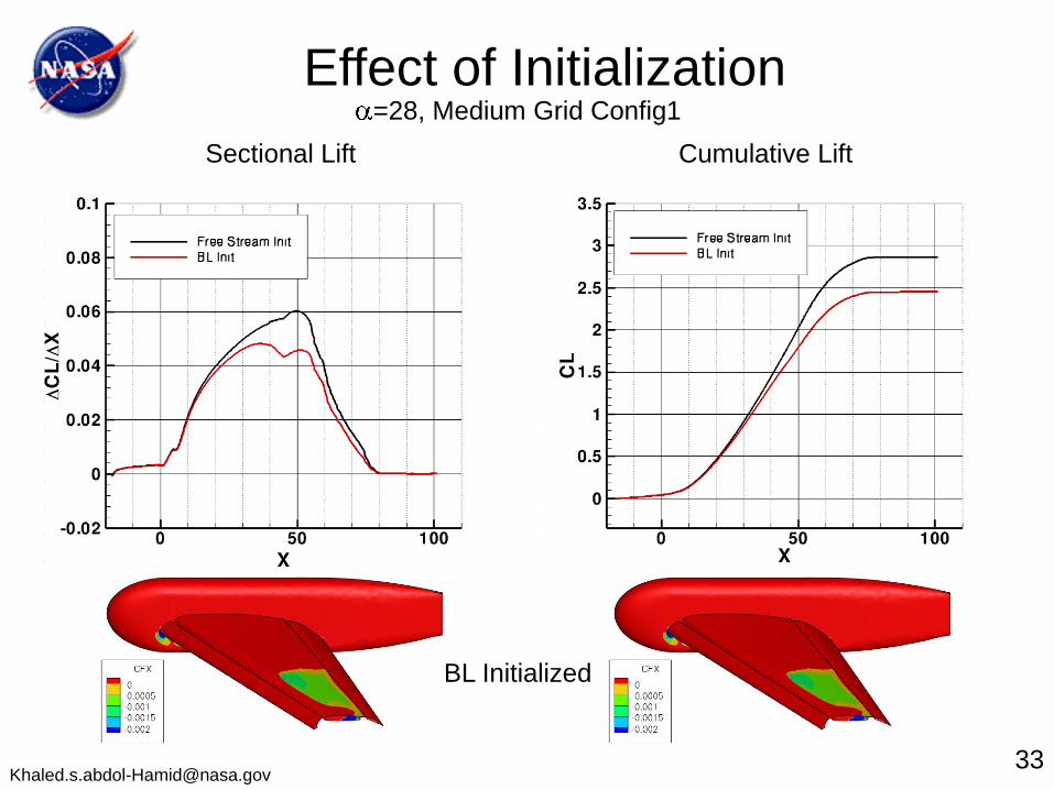
Sectional Lift Cumulative Lift
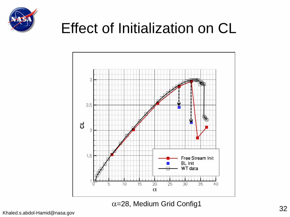
=28, Medium Grid Config1
Effect of Initialization
BL Initialized
33

=28, Medium Grid Config1
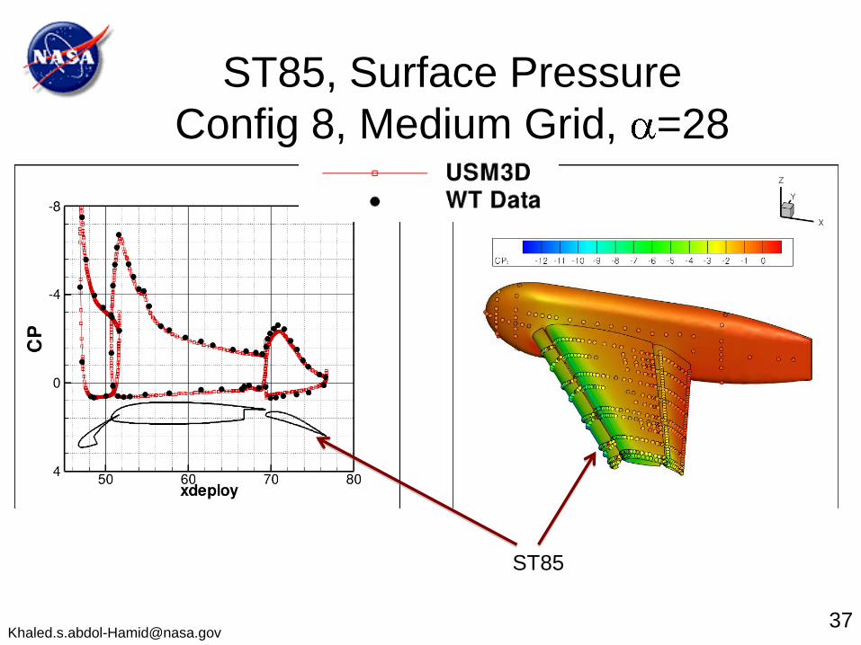
Effect of Initialization on Surface Pressure
34
Free Stream BL