cfd analysis of heat transfer enhancement of a …...figure 2.1 shown cad model of radiator designed...
TRANSCRIPT

CFD Analysis of Heat Transfer Enhancement
of A Car Radiator using Nanofluid
as A Coolant
Vinod M. Angadi
1,
P G. Student: Thermal Power Engineering,
Gulbarga /Karnataka/India
R. Nagaraj2,
Associate Professor: Mechanical Department,
PDA College of Engineering.
Gulbarga/Karnataka/India
Dr. O. D. Hebbal
3
Professor: Mechanical Department,
PDA College of engineering.
Gulbarga/Karnataka/India
Abstract - In automobiles radiators like car is device
performed to cool by circulating fluid in it, which consist of
water as a coolant or a mixture of water and some external
additives like anti freezing materials like ethylene glycol these
fluids added to water, this mixture we called as a base fluid. For
our analysis in this paper,the heat transfer performance of pure
water has been compared with their binary mixtures of Al2O3.
Different amounts of nanoparticle have been added into these
base fluids and its effects on the heat transfer performance of
the car radiator have been analysis done using STAR CCM+
tool. In this paper Al2O3 particles are taken as an external
additives used for enhancement of the thermal conductivity and
heat transfer of the car radiator. So in car radiator liquid flow
rate has been changed in the range of 2-6 litter per minute and
fluid inlet temperature has been changed for all the
experiments. The result shows that nanofluids clearly enhance
heat transfer compared to their own base fluid. In the best
conditions, the heat transfer enhancement of nano fluids more
which can be compared to usual coolant used in radiator. The
implementation of nanofluid increases the overall heat transfer
coefficients determind in this paper.
Keywords: ethylene glycol ,nanofluids, Base fluids, star ccm+,
aluminium oxide, enhancement
1. INTRODUCTION
Water is the most widely used coolant for the heat
exchangers in the thermal industry and in automobiles like car
radiators, this device where more amount of heat is to be
carried by the coolant to get effective performance from the
radiator, we need to have good coolant and some additives,
that will help in the base fluid, as the agents for enhancing the
heat transfer, In this experiment we use water as the base fluid
with small amount of the nano-fluids. Usually heat transfer
fluids with suspended ultra fine particles of nanometre size are
named as nanofluids, which have opened a new dimension in
heat transfer processes. The recent investigations confirm the
potential of nanofluids in enhancing heat transfer required for
present age technology. The present investigation goes
detailed into investigating the increase of thermal conductivity
with temperature for nano fluids with water as base fluid and
particles of Al2O3 as suspension material [1]. Nano particles
materials are placed in form of suspension solid particles,
inside the cooling fluids can effectively enhance the thermal
quality of base fluid. It is well known that metals and metal
oxides have higher thermal properties compared to
conventional fluids. Nano-fluids are the ultra fine particles
they may in the form of solid of metallic, made to suspend or
dissolve in the base fluid. They are measured in size of
nanometre (nm). From recent nano-technological research
proved that they increase the properties of the basic coolants
like, heat transfer capacity and thermal conductivity of the
coolants, by adding small amount of the nano-particles to the
base fluids. Present analysis is carried on The Increase in heat
transfer capacity with variation of the size and amount of use
in base fluid (water). This analysis is results of heat transfer
and thermal conductivity enhancement will be seen at the end
of the analysis. Results from the simulation values made to
compared with the standard journels. Standard radiator model
shown below taken for analysis [2]
Figure 1.1: Schematic diagram of the Radiator [2].
2. METHODOLOGY
Using computational fluid dynamic softwares availble to
use like in STAR CCM+ tool. Simulation of the automobile
radiator is carried out. Using nano fluids in the car radiator,
enhanced thermal conductivity of the fluid is determined
experimentally to do the analysis on the complex projects it
cost more and time also consumes lot. More space and man
International Journal of Engineering Research & Technology (IJERT)
Vol. 3 Issue 8, August - 2014
IJERT
IJERT
ISSN: 2278-0181
www.ijert.orgIJERTV3IS080809
(This work is licensed under a Creative Commons Attribution 4.0 International License.)
1058
power needed to carry out externally and some other
negatives seen. But software analysis using computer is very
useful because, its portable and very less cost needed
compared to the practical work. Boundary conditions,
iteration values, input values, easily variables in computer
compared to practicle. where in experimental it’s very costly
to do experiments again and again by varying in input values
like boundary conditions for models. So the CFD is tool to
use in the analysis problems so here we vary the values
easily without any problem.To obtain the higher heat transfer
rate, and gradual increase in the thermal conductivity of the
fluid, the aluminium oxide nano particle is the one it will give
enhanced output from the radiator, mixing is done by the
certain volumetric concentrations of the nano fluids to the
basic fluid like water and vary the nano particle
concentration to from 1% to up to the 6% to the water and
made pass through the inlet of the radiator for analysis
purpose [2]. In this analysis considered only the one part of
the car radiator as heat exchanger to carry out the analysis,
the radiators made to with long rectangular sections and at
both side 51 fines are to makd to carry the heat from the
plate. Fins are so arranged to the plate that only small part of
the fins is come in contact with the long plate. The design of
the heat exchanger fin, is made using CAD design in STAR-
CCM+ software. radiators normally face different
environmental conditions to operate, so these have to come
out extreme cold and extreme hot conditions to work
effectively without any problem, with better efficiency and
long life. This kind of the model made to design using the
effective tools. It has been proved that conventional fluids,
such as water and Ethylene Glycol have poor convective heat
transfer performance and therefore high compactness and
effectiveness of heat transfer systems are necessary to
achieve the required heat transfer [3]. Among the efforts for
enhancement of heat transfer the application of nanoparticle
additives to liquids is more noticeable and currently a large
number of investigations are devoted to this subject.
Table 2.1: Discreption of the CAD model
CAD model with dimensions are given in Table 2.1.
radiator parts is designed by taking only one part of the actual
radiator, hown in Figure 1.1,which is used for analysis. One
of the main important part in analysis of model is meshing of
the model. In this project different kind of meshing done to
different surface made different parts like, long plate for inlet
of water into the radiator,and the interface with plate and
curve part of the fin more fine mesh is to be done, one to get
heat transfer values exactly.and next one is the face of the fin
which has more surface area compared to other part of the
fine where normal meshing can be taken, and for at side of
the fines it made cut from othe fines so it actualy single fin
but our understandin and analysis we made equall half of fin
so one cut part fine side is taken periodic coditions to the next
part fin to start continues from that part,so at this part very
fine meshing is done. Detailed methodology of the project are
explained above. By applying the datasin the boundary
conditions.we can get the analysis results from the radiators
varing the inlet nanofluid concentraioms to the water.
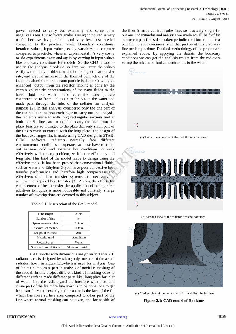
(a) Radiator cut section of fins and flat tube in centre
(b) Meshed view of the radiator fins and flat tubes.
(c) Meshed view of the radiaor with fins and flat tube intrface
Tube length 31cm
Number of fins 34
Space between tubes 1.5cm
Thickness of the tube 0.3cm
Length of the tube 2cm
Material used Aluminum
Coolant used Water
Nanofluids as additives Aluminum oxide
International Journal of Engineering Research & Technology (IJERT)
Vol. 3 Issue 8, August - 2014
IJERT
IJERT
ISSN: 2278-0181
www.ijert.orgIJERTV3IS080809
(This work is licensed under a Creative Commons Attribution 4.0 International License.)
1059
Figure 2.1: CAD model of Radiator

Figure 2.1 shown CAD model of Radiator designed
taken from Table 2.1 and in Figure 2.1 (a) only one part of
the radiator made used for analysis perpose. With long flat
tube with both side fins are arranged for heat transfer. 51 fins
are present each side of the flat tube. Second figure 2.1(b)
meshed parts of fins and flat tubes arrangement at different
mesh sizes are observed.and figure 2.1(c) Closed view of the
fins and flat tubes are shown where different surface of the
fins interfaced with flat tube [3].
3. DATA AND RESULTS
Fin: Radiator analysis is done for different concentration
of the nanofluids with water. For fin we taken material as
aluminium that having the properties like density of 2702.0
kg/m3, and the specific heat of 903.0J/kg-K.,thermal
conductivity of 237.0 W/m-K, respectively. and minimum to
maximum allowable temperature is given from range of
1000K to 5000K respectively in the analysis. 400C is static
temperature taken in initial conditions. Steady flow and three
dimensional and material taken solid since it’s is aluminium
plate. In conditions the properties of the fines remain
constants, so in complete analysis of the radiators these
values remain kept same and constants. Since air is come
into contact with the fine at outside, the convective boundary
condition is taken in analysis [3].
Water: In the assigning the boundary conditions of the
radiators for incoming water to the plate section lot many
basic operations are to be done simultaneously like we have
assign on boundaries for inlet of the water, temperature,
velocity, mass flow rate, mass flow directions all these are
assigned and made changed depending on the concentrations
of the fluids we use. Since water is having different
concentration of nanofliud of aluminium oxide.In every new
analysis so for every time we have to change the boundary
conditions for each iterations of the nanofluids, values of the
inflow fluids to radiator is given by the tables and simulation
values and results are shown below. And the performance
values of the radiator from the simulation results are shown
Figure 4.1 and Figure 4.2
6. Overall heat transfer:
(W/m2 k) (3.9)
C. Boundary Conditions and Physics Selected
One of the most important operations of the fluid
flow analysis of the radiator heat transfer is the applying the
boundary conditions to the geometric parts of the radiators.
According to the output requirement. we specify the
respective inlet boundaries for the parts in the region. Let’s
see the different boundaries for radiators. The conservation
equations of mass, momentum, and energy mentioned above
equation (3.1) to (3.3) are nonlinear and coupled systems,
which are solved subjected to the following boundary
conditions. At the inlet of the flat tube, uniform axial velocity
and temperature are prescribed. The inlet velocity determines
the Reynolds number of the flow, and the inlet temperature
has been taken as 50, which is typical for automotive
radiators. The uniform axial velocity at the inlet assumed in
the present study is an idealization of the actual flow pattern
because considerable flow non uniformities arising from the
fluid entering the top of the radiator will be inevitable in the
actual case. At the outlet section of the tube. In STAR CCM+
the outflow boundary condition corresponds to fully
developed velocity and temperature profiles, so that the axial
derivatives of the velocity and the temperature at the exit
plane are zero. For a higher reynolds number, the flow is not
fully developed. Under such a condition, a pressure outlet
boundary condition is adopted. All along the tube wall, a no-
slip boundary condition is imposed for velocity. For an
automobile radiator, a realistic thermal boundary condition on
the outside of the wall is a prescribed free stream
temperature. In our simulations, following Park and Pak
(2002) [5] and an ambient air temperature of 300C were
selected. This represents a mean vehicle speed between the
idle and the full speed of 72 km/h [5].
FINS: Boundaries for the fins are different
compared to inlet of the water to the radiators, initial
conditions to the fines like inlet temperatures taken as the
ambient 500C and the convective heat transfer coefficient is
given 50W/m2K.and by the different fin parts are to assigned
respectively. At the edge of the fin assigned as the periodic
type of the boundary conditions, periodic boundary condition
is the one which will treat fin as complete. For the meshing of
fines in complicated regions increase the mesh density in
those regions meshing with finer mesh quality will give
better result in that region. adjust the mesh size wherever
need for correct results, selected mesh conditions like surface
remesher, polyhedral mesher,and the prism layer these are
the types of mesh used. After that part have to select physics
to respective regions so that physical conditions are taken to
the applied regions in the analysis of the radiators.
Water: In regions, the water made to pass through
the plain rectangular flat tube of the width 0.03cm, length of
2cm, and height of 31cm [3-5] from Figure 1.1 at inlet of the
boundary condition for the water is given the temperature and
flow directions and the velocity, flow rate and flow is laminar
has to be match with physics of the water given in the step
continua, inlet boundary conditions given thet temperature of
the water or in coming coolant with different concentrations
International Journal of Engineering Research & Technology (IJERT)
Vol. 3 Issue 8, August - 2014
IJERT
IJERT
ISSN: 2278-0181
www.ijert.orgIJERTV3IS080809
(This work is licensed under a Creative Commons Attribution 4.0 International License.)
1060
A. Governing Equations
1. Continuity Equation: (∇.𝑉) = 0 (3.1)
2. Momentum Equations: 𝜌𝑛𝑓(∇.𝑉) V=∇P+𝜇𝑛𝑓∇2V (3.2)
3. Energy Equations: 𝜌𝑛𝑓∁𝑝𝑛𝑓(∇.𝑉)T=𝑘𝑛𝑓∇2𝑇 (3.3)
B. Formula used
1. Flow rate of the coolant: q = (1000*60) m/s. (3.4)
2. Flow rate for each tube: = (flow rate)/(number of tube) (3.5)
3. Density (ρ): = mass/volume m^3 (3.6)
4. Mass flow / tube: = (mass flow rate for each tube * ρ)
= m ̇/ (tube) = Q/ (tube) (3.7)
5. Velocity = (flow rate per tube)/ (tube area):
= (Q/ (tube))/At m^3/s (3.8)
of the nanofluid. As per our analysis for coolants the
temperatures of the coolants must be more compared to when
coming out from the radiators. that will results in the increase
in the heat transfer from the coolants can be seen as per
physical condition inlet and out let of the fluid.in selection of
the physics for model for water considered as flow is laminar.
Liquid, Three dimensional flow, constant densiti .stady flow,
coupled energy,coupled energy. And in the fins thephysica
are considered, constant density couplee solid energy
gradiants, solid, stady, three dimensional. these are respectve
physics taken for the analysis of the radiator. Using this
physical values boundary are applied in regions.
4. SIMULATION RESULTS AND ANALYSIS
Simulation analysis of the car radiatoris donefor different
vloumetric flow rates varing from 2 to 5 l/min of base water
to that small quantity of the nanoparticles are addedto it to get
analysis the enhancement of the the thermal conductivity of
the fluid in the radiator. after adding the nanofluids to the
base fluid enhanced heat transfer and mass flow results are
shown. In following heat transfer graphs analysis results are
given for 1% 3% 4% 6% of nano fluids at volumetric flow
rate of 5 litter per minute. For each % of flow rate [3-5]
(a) (e)
(b) (f)
(c) (g)
(d) (h)
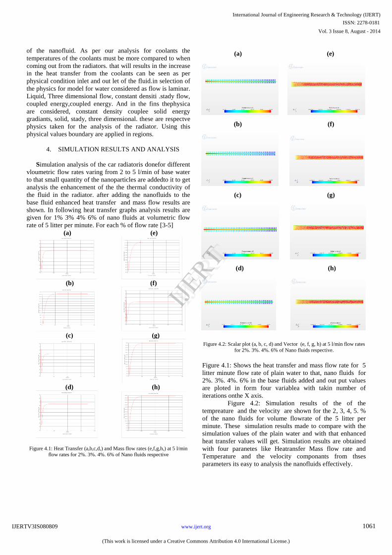
Figure 4.1: Heat Transfer (a,b,c,d,) and Mass flow rates (e,f,g,h,) at 5 l/min
flow rates for 2%. 3%. 4%. 6% of Nano fluids respective
Figure
4.2: Scalar plot
(a,
b,
c,
d) and Vector
(e,
f,
g,
h) at 5 l/min flow rates
for 2%. 3%. 4%. 6% of Nano fluids respective.
Figure 4.1: Shows the heat transfer and mass flow rate for 5
litter minute flow rate of plain water to that, nano fluids for
2%. 3%. 4%. 6% in the base fluids added and out put values
are ploted in form four variablea with takin number of
iterations onthe X axis.
Figure 4.2: Simulation results of the of the
tempreature and the velocity are shown for the 2, 3, 4, 5. %
of the nano fluids for volume flowrate of the 5 litter per
minute. These simulation results made to compare with the
simulation values of the plain water and with that enhanced
heat transfer values will get. Simulation results are obtained
with four paranetes like Heatransfer Mass flow rate and
Temperature and the velocity componants from thses
parameters its easy to analysis the nanofluids effectively.
(a) (e)
(b) (f)
(c) (g)
(d) (h)
International Journal of Engineering Research & Technology (IJERT)
Vol. 3 Issue 8, August - 2014
IJERT
IJERT
ISSN: 2278-0181
www.ijert.orgIJERTV3IS080809
(This work is licensed under a Creative Commons Attribution 4.0 International License.)
1061
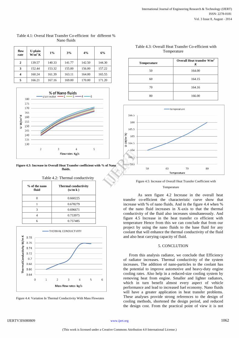
Table 4.1: Overal Heat Transfer Co-efficient
for different %
Nano fluids
Figure
4.3:
Increase in
Overall Heat Transfer coefficient with % of Nano
fluids.
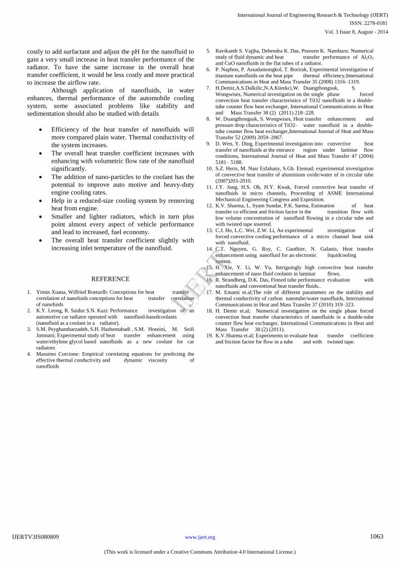
Table 4.2: Thermal conductivity
Table 4.3: Overall Heat Transfer Co-efficient with
Temperature
Temperature Overall Heat transfer W/m2
K
50 164.00
60 164.15
70 164.16
80 166.00
Figure 4.5: Increase of Overall Heat Transfer Coefficient with
Temperature
As seen figure 4.2 Increase in the overall heat
transfer co-efficient the characteristic curve show that
increase with % of nano fluids. And in the figure 4.4 when %
of the nano fluid increases in X-axis to that the thermal
conductivity of the fluid also increases simultaneously. And
figure 4.5 Increase in the heat transfer co efficient with
temperature Hence from this we can conclude that from our
project by using the nano fluids to the base fluid for any
coolant that will enhance the thermal conductivity of the fluid
and also heat carrying capacity of fluid.
5. CONCLUTION
From this analysis radiator, we conclude that Efficiency
of radiator increases. Thermal conductivity of the system
increases. The addition of nano-particles to the coolant has
the potential to improve automotive and heavy-duty engine
cooling rates. Also help in a reduced-size cooling system by
removing heat from engine. Smaller and lighter radiators,
which in turn benefit almost every aspect of vehicle
performance and lead to increased fuel economy. Nano fluids
will have a greater application in heat transfer problems.
These analyses provide strong references to the design of
cooling methods, shortened the design period, and reduced
the design cost. From the practical point of view it is not
flow
rate
U-plain
W/m2
K
1%
3%
4%
6%
2
139.57
140.33
141.77
142.50
144.30
3
152.44
153.32
155.00
156.00
157.22
4
160.24
161.39
163.11
164.00
165.55
5
166.21
167.16
169.00
170.00
171.20
% of the nano
fluid
Thermal conductivity
(w/m k )
0
0.660225
1
0.678279
3
0.696671
4
0.753975
6
0.757485
International Journal of Engineering Research & Technology (IJERT)
Vol. 3 Issue 8, August - 2014
IJERT
IJERT
ISSN: 2278-0181
www.ijert.orgIJERTV3IS080809
(This work is licensed under a Creative Commons Attribution 4.0 International License.)
1062
Figure 4.4: Variation In Thermal Conductivity With Mass Flowrates
costly to add surfactant and adjust the pH for the nanofluid to
gain a very small increase in heat transfer performance of the
radiator. To have the same increase in the overall heat
transfer coefficient, it would be less costly and more practical
to increase the airflow rate.
Although application of nanofluids, in water
enhances, thermal performance of the automobile cooling
system, some associated problems like stability and
sedimentation should also be studied with details
Efficiency of the heat transfer of nanofluids will
more compared plain water. Thermal conductivity of
the system increases.
The overall heat transfer coefficient increases with
enhancing with volumetric flow rate of the nanofluid
significantly.
The addition of nano-particles to the coolant has the
potential to improve auto motive and heavy-duty
engine cooling rates.
Help in a reduced-size cooling system by removing
heat from engine.
Smaller and lighter radiators, which in turn plus
point almost every aspect of vehicle performance
and lead to increased, fuel economy.
The overall heat transfer coefficient slightly with
increasing inlet temperature of the nanofluid.
REFERENCE
1. Yimin Xuana, Wilfried Roetzelb: Conceptions for heat transfer
correlation of nanofuids conceptions for heat transfer correlation
of nanofuids 2. K.Y. Leong, R. Saidur S.N. Kazi: Performance investigation of an
automotive car radiator operated with nanofluid-basedcoolants
(nanofluid as a coolant in a radiator). 3. S.M. Peyghambarzadeh, S.H. Hashemabadi , S.M. Hoseini, M. Seifi
Jamnani; Experimental study of heat transfer enhancement using
water/ethylene glycol based nanofluids as a new coolant for car radiators
4. Massimo Corcione: Empirical correlating equations for predicting the
effective thermal conductivity and dynamic viscosity of nanofluids
5. Ravikanth S. Vajjha, Debendra K. Das, Praveen K. Namburu: Numerical
study of fluid dynamic and heat transfer performance of Al2O3 and CuO nanofluids in the flat tubes of a radiator.
6. P. Naphon, P. Assadamongkol, T. Borirak, Experimental investigation of
titanium nanofluids on the heat pipe thermal efficiency,International Communications in Heat and Mass Transfer 35 (2008) 1316–1319.
7. H.Demir,A.S.Dalkilic,N.A.Kürekci,W. Duangthongsuk, S.
Wongwises, Numerical investigation on the single phase forced convection heat transfer characteristics of TiO2 nanofluids in a double-
tube counter flow heat exchanger, International Communications in Heat
and Mass Transfer 38 (2) (2011) 218–228. 8. W. Duangthongsuk, S. Wongwises, Heat transfer enhancement and
pressure drop characteristics of TiO2– water nanofluid in a double-
tube counter flow heat exchanger,International Journal of Heat and Mass Transfer 52 (2009) 2059–2067.
9. D. Wen, Y. Ding, Experimental investigation into convective heat
transfer of nanofluids at the entrance region under laminar flow conditions, International Journal of Heat and Mass Transfer 47 (2004)
5181– 5188.
10. S.Z. Heris, M. Nasr Esfahany, S.Gh. Etemad, experimental investigation of convective heat transfer of aluminium oxide/water nf in circular tube
(2007)203-2010.
11. J.Y. Jung, H.S. Oh, H.Y. Kwak, Forced convective heat transfer of nanofluids in micro channels, Proceeding of ASME International
Mechanical Engineering Congress and Exposition.
12. K.V. Sharma, L. Syam Sundar, P.K. Sarma, Estimation of heat transfer co efficient and friction factor in the transition flow with
low volume concentration of nanofluid flowing in a circular tube and with twisted tape inserted.
13. C.J. Ho, L.C. Wei, Z.W. Li, An experimental investigation of
forced convective cooling performance of a micro channel heat sink with nanofluid.
14. C.T. Nguyen, G. Roy, C. Gauthier, N. Galanis, Heat transfer
enhancement using nanofluid for an electronic liquidcooling system.
15. H. Xie, Y. Li, W. Yu, Intriguingly high convective heat transfer
enhancement of nano fluid coolants in laminar flows.
16. R. Strandberg, D.K. Das, Finned tube performance evaluation with
nanofluids and conventional heat transfer fluids..
17. M. Emami et.al;The role of different parameters on the stability and thermal conductivity of carbon nanotube/water nanofluids, International
Communications in Heat and Mass Transfer 37 (2010) 319–323.
18. H. Demir et.al; Numerical investigation on the single phase forced convection heat transfer characteristics of nanofluids in a double-tube
counter flow heat exchanger, International Communications in Heat and
Mass Transfer 38 (2) (2011). 19. K.V.Sharma et.al; Experiments to evaluate heat transfer coefficient
and friction factor for flow in a tube and with twisted tape.
International Journal of Engineering Research & Technology (IJERT)
Vol. 3 Issue 8, August - 2014
IJERT
IJERT
ISSN: 2278-0181
www.ijert.orgIJERTV3IS080809
(This work is licensed under a Creative Commons Attribution 4.0 International License.)
1063