cf 59 12 64
DESCRIPTION
http://www.energyfromthorium.com/pdf/CF-59-12-64.pdfTRANSCRIPT

x-822
OAK RIDGE NATIONAL LABORATORY Operated by
UNION CARBIDE NUCLEAR COMPANY
Division of Union Carbide Corporation
Post Office Box X Oak Ridge, Tennessee
DATE: JanUaI'Y 12, 1960
SUBJECT: Molten-Salt Breeder Reactors
TO: Distribution
FROM: H. G. MacPherson
Abstract
AUTHORIZED
ORNL I I CENTRAL FILES NUMBER 1 59-12-64 I (Revised)
COPY NO. 7 8
The problems involved i n building a molten-salt thermal-brkeder reactor are reviewed, and it is concluded that the most feasible construction is an externally-cooled reactor with the f'uel salt passing through the reactor core i n p p h i t e tubes. A reactor with l5$ of the core volume occupied by fuel salt and 5$ occupie . by fertile salt would have a net breeding ra t io of about 1..06. The specific power i s about 3.0 Mw(tb) per kg of U-233, U-235, and Pa i n the entire reactor and chemical processing system. The resulting doubling time is 13 all-power years. fuel cycle for a 1000-Mw(E) station with this breeding performance is estimated t o be 1.2 mills/kwhr. material uti l ization is an output of 1.18 Mw(E) per kg of U-233, U-235 ana Pa, and 3.2 Mw(E) per metric ton of thorium. The latter figure could be increased by a factor of two at a sacrifice of 0.01 in breeding ratio.
The cost of the
The performance i n terns of
NOTICE I
This document contains information of a preliminary nature and was prepared primarily for internal use at the Oak Ridge National Laboratory. It i s subiect to revision or correction and therefore does not represent a final report. The information i s not to be abstrocted, reprinted or otherwise given public dissemination without the approval of the ORNL patent branch, Legal and Information Control Department.
el
. -.._

2
MOLIPEIV-SALT BREEDER REACTORS
The purpose of this memo i s t o examine and summarize the status of the molten-salt reactor as meeting the requirements of a breeder with a doubling time of not more than 25 years-. Included are a discussion of:
1 t,,..
1. The practicability of diffeYent types of breeder reactor construction.
2, The parer density attainable in the fuel salt.
3.
4.
The status and cost of the required chemical processing scheme.
The breeding gain, specific power, and doubling time consistent with reasonable assumptiones concernfng items (l), (2), and (3).
5 . 'Ilhe feasibili'ty and coet of molten-salt reactors.
The contents of this memo have not been subjected t o 8,Oalysis by the Thermal- Breeder Evaluation group. Their work wi l l be largely independent of this, and their results, when available, w i l l take precedence over the numbers used i n this memo.
i
H11 I. Reactor Construction
Three types of breeder reactor construction are discussed: tube construction, the graphite-core-shell construction, and an internally- cooled construction.
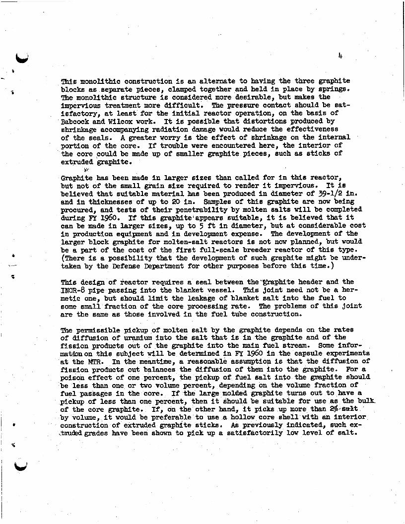
U n i t Fuel Tube Construction - The type of construction that is believed t o be most practical a t present for a molten-salt breeder reactor i s one in which the fuel salt passes through the reactor i n graphite tubes, Graphite moderator is massed outside of the fuel tubes in the core region of the reactor, and blanket salt containing thorium surrounds the core, The blanket salt also passes through small passages in the moderator graphite and cools ito Fig. 1 (ORML-LR-Dwg. 42242) gives a schematic representation of one edge of such a reactor, showing a single Fuel tube, one of many. Although Fig. 1 s h m a re-entrant graphite tube with both in l e t and outlet at the bottom end t o avoid problems of differential thermal expansion, it may also be possible t o ubre a construction in which the fuel tubes go straight through the reactor.
The fuel tubes would be manuf'actwed from fine-pained extmded graphite rendered impervious by one of a number of treatments available. of graphite has been shown t o be the most impervious t o molten salts; one
the unit-fuel-
=
This type c.
jr% rc 3-

L, 5 . - .
5
. -
4
c . . *
3
such grade has been used i n contact with flawing salt streams for a year with no evidence of attack or bulk penetration by the salt. Separate tes t s have indicated that sluch a grade of graphite will soak up less than one per-
+@fatof salt by volume when pressures of up t o 150 psi are applied; i n fact, one grade picked up less than Oo2$ by volume of salt. Tubes 3-3/4 Yn. ID x 5 in. OD are on order and wi l l be tested within a few months.
The moderator p p b i t e w i l l be in the blanket salt environment, and the I @ladset salt will be maintained under sl ight pressure with respect t o the fuel salt so that m y leakage that develops wi l l be from blanket salt t o fuel salt. compared t o the rate of chemical procrassing of the fuel salt, graphite could also be made from fine-grained extruded graphite t o keep pick- up of salt i n it aWSar low a level as possible. tubes and pressurizing the blanket salt with respect t o the fuel salt, f i s - sioning within graphite w i l l be kept t o a minimum. l i t t l e reason t o expect buildup of fission-product poisons i n the graphite.
In the re-entrant fuel-tube construction, two metal-to-graphite connections are necessary. mechantcally sound connection, smb as a s l i p f i t , since a small leakage here would only bypass s small amount of fuel from going through the reactor corer The connection of the outer fuel tube t o the metal wall of the reactor should be reasonably t ight , with leakage small relative t o chemical processing rate of the fuel. The three possibil i t ies for this joint are a flanged joint with a mechanical pressure seal, a frozen-salt plug seal, and a brazedmetal- to-graphite tube junction. type flanged joints with some success, and it i s presumed that th i s will be a feasible solution t o the problem. i s under way at ortk Ridge, and early indications are that it will be possible t o braze graphite t o INOR-8, probably by the use of pure molybdenum as an in- termediate material t o provide a match t o the thermal expansfon coefficient t o the graphite.
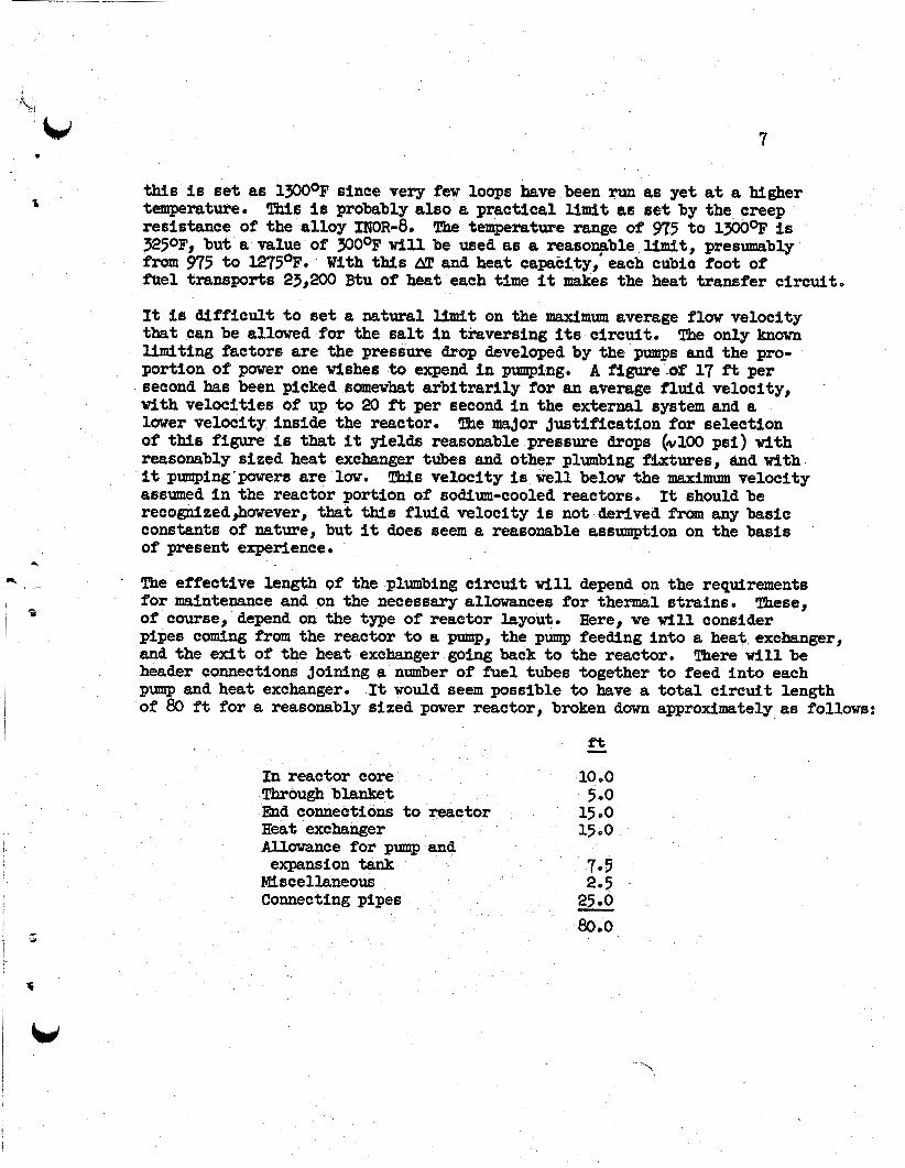
Graphite Core Shell Construction - A simple construction for a small bra- region reactor with a graphite core shell is shown in Ffg. 2 (ORNbIJR-Dwg. 37258). As sham i n the drawing, the corn is made from three large blacks of graphite, a top header, a bottom header, and a center section* diameter of the core i s approximated 54 in., and the height of the center section would be about 40 in. It is proposed that these graphite parts be made from large-size molded-graphite blocks, that the blocks be rough machined t o shape, and that they then be impregnated and tm&edto make them nearly impermeable to molten salts. ternal. parts would be done before treatment and the parts olamped together during treatment t o cement the headers on and yield a monolithic block con- s truction .
bakage can be tolerated provided it is at a rate that is small The moderator
By confining the fuel t o
AB a result there is
me connection to the central graphtte tube need only be a
Babcock and Wilcox have experimented with pressure
The testing of the freeze plug technique
The
It is possible that f ina l machining on the in-
4
5
a
\ -
c
!Ibis monolithic construction i s an alternate t o having the three graphite blocks as separate pieces, clamped together and held i n place by springs. The monolithic structure is considered more desirable, but makes the impervious treatment more difficult . The pressure contact should be sat- isfactory, a t least for the initial reactor operation, on the basis of Babcock and Wilcox work. shrinkage accompanying radiation damage would reduce the effectiveness of the seals. portion of the core, If trouble were encountered here, the interior of the core aouldbe made up of smaller graphite pieces, such as sticks of extruded graphite.
Graphite has been made i n larger sizes than called for i n %hi8 reactor, but not of the small grain size required t o render it impervious. believed that suitable material has been produced i n diameter of 39-1/2 in. and in thicknesses of up t o 20 in. Samples of this graphite are now being procured, and testa of the i r penetrability by molten salts w i l l be completed during FY 1960. If this graphlte'appears suitable, it is believed that it can be made i n larger sizes, up t o 5 f't i n diameter, but a t considerable cost in production equipment and i n development expense. The development of the larger block graphite for molten-salt reactors is not now planned, but would be a part of the cost of the first full-scale breeder reactor of t h i s type. (There is a possibility that the development of such graphite might be under- taken by the Defense Department for other purposes before this time.)
This design of reactor requires a seal between the 'mph i t e header and the INOR-8 pipe passing into the blanket vessel. metic one, but should l i m i t the leakage of blanket salt into the fuel t o some small fraction of the core processing rate. are the same as those involved in the fuel tube construction,
It is possible that distortions produced by
A greater worry is the effect of shrinkage on the internal
V !
It is
This joint need not be a her-
The problems of this joint
The permissible pickup of molten salt by the graphite depends on the rates of diffusion of uranium into the salt that is in the graphite and of the fission products out of the graphite into the main fuel stream. matdonon this subject w i l l be determined i n FY 1960 i n the capsule experiments at the MTR. In the meantime, a reasonable assumption i s that the diffusion of fission product6 out balances the dfff'usion of them into the graphite. poison effect of one percent, the pickup of fuel salt into the gcephite should be less than one or two volume percent, depending on the volume fraction of fuel passages i n the core. If the large moltled graphite turns out t o have a pickup of less than one percent, then it should be suitable for use as the bulk. of the core graphite. If, on the other had , it picks up more than 2$.s&Et '
by volume, it would be preferable t o use a hollow core $hell with an inter ior construction of extruded g r a p ~ t e stick$. AB previously indicated, such ex- ,Drudedgrades have been shown to pick up a satisfactorily law level of salt.
Some infor-
For a

5
Internally-Cooled Reactor - Various designs of internally-cooled molten-
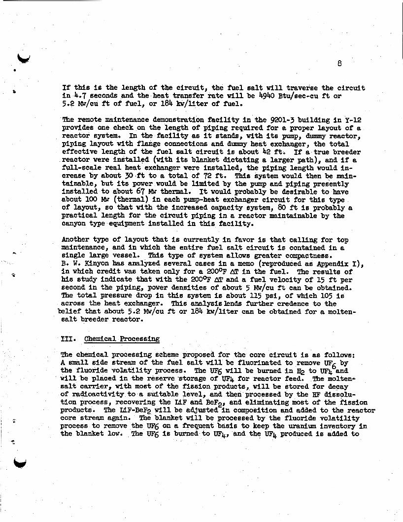
i n Fig. 3. In this concept, the fuel is contained in graphite tubes about O.5;tn.ID x 0.7 in. OD that extend through the moderator, well into the blanket region. *The tubes are connected a t each end by brazed joints t o a metal header system 60 that the fuel can be circulated slowly t o keep it uniform, t o remove gaseous fission products, and t o allow fuel concentration adjustment as burnup proceeds. Preeumably the tubee would have graphite in- serts forcing the fuel t o the periphery of the tubes i n the core region and occupying most of the internal volume of the tubes i n the blanket region. The heat generated in the fuel would be transferred through the tube wall t o the blanket salt which is used as a coolant. the heat generation t o perhaps 50 kw per tube averaged over the reactor, and would therefore require 10,000 tube8 for a reactor &likering 200 elec- t r i c a l megawtts of power.
Althou& no brazed joint that is completely satisfactory i n terms of com- pa t ib i l i ty with the salt ha8 yet been demonstrated, there i s l i t t l e doubt but that such a joint w i l l be demonstrated during this f i sca l year. use of molybdenum as an intermeaitate nipple connection has been demonstrated, and brazing nraterials that w e t graphite and are campatible with the salt have been found. Thus, i n a l l probability, there w i l l be no single technical element of infeasibility remaining by the end of this f i sca l year for an internally-cooled reactor. maintaining their integrity during a long reactor lifetime is not very attrac- tive, a t least t o this writer. is a greater specific power, but it I s doubtful i f the internally-cooled reactor can achieve more than a factor of two in specific power over an externally-cooled molten-salt reactor.
- b salt reactors have been suggested. One of the simplest i s shown i n concept
This would probably l i m i t
The
* -
Nevertheless, the concept of 10,000 tubes a l l f 9
The advantage hoped for with internal cooling
Stamnary - The unit-fuel-tube construction seem t o be a feasible configuration for a breeder reactor. By the en& of this fiscal year it should be possible t o specify suitable types of graphite for both Riel tubes and moderator, and t o specify a sa t i s f ac toh end connection for the tubes. The construction avoids most of the possible problems involved i n soaking of f u e l i n t o , t h e graphite since the fuel contacts only a small portion of the moderator graphite. Furthermore, it wil l use the type of graphite that is now deemed least l ikely t o soak up fuel salt.
The graphite-core-shell construction requires graphite of a size and quality that is not m e d i a t e l y available, and w i l l probably not be available without the expenditure of a few mfllion dollars of development money. ture were made, the reactor construction would have a good chance of success. However, the earlier availability of the fuel tube construction makes it the first choice.
If this expendi- e
E

b f
I I
6
c
e
. - L Y
4
The fntePnally..eooled reactor has some attraction i n terms of higher specific power and is made up of elements thaf individually seem quite feasibleo great complexity of the core and the probable inaccessibility of it for minor repairs make it unattractive at thos stage of the technology.
The reference reactor for the remainder of thirs memo is then taken t o be of the h e 1 tube construction, with 15 vo1 $ of' the core occupied by fuel salt, 5s by blanket salt, and the r-ining 80s by graphite. If the fuel tubes are 3-3/4 in. ID , the fuel tubee wi l l be $peed on 8-5/8 ino centers on a square axray.
The
11. m e r Density
The nuclear calculation K i l l yfeld the breeding rat io and the uranfum con- centration required in the ea l t t o make the reactor cr i t ical . In a circu-
lating f i e 1 reactor, the l a t t e r figure must be combined with the power that can be extracted per rmf t volume of h e 1 salt t o yfeld a gross figure for epecifYc power. at in two wayst factors involved, and the other is t o lay out specific designs and Bee w h a t their volumes are, asti haw much power they take care of. We w i l l first look at the problem generally rend then examine specific layouts that have been proposed.
The power obtainable pkr unit volume of salt can be arrived one 18 a general approach that looks a t the fundamental
A reasonable value of the parer density in the fuel can be.eetimated *om the to t a l length of piping required in the sptem. considered is that required t o carry the f i e1 salt into and out of the reactor, through the blanket, through header connectionrs, through the heat exchanger and the' equi'valent length of piping represented by the pump volute and expanslion tax$, piping, and a sa? temperature range between reactor entrance and exit. information cmb
The length of piping
An average flufd velocity Ki l l be assumed through this Thie
ed with the volumetric epecific heat of the salt determines the amount of hea p transferred per uni t volume of salt.
The the fuel salt w i l l be about @?mole (k ISF, 37 mole $ BeF2, The volumetric heat e a p c i t y of this mixture i s about
temperature, or 77.5 Btu/eu f t -OF . The melting point of the fuel i s about 8500Fp and a figwe about 100% above this should be used as the minfmm bulk fluid temperature.
the m i n i m u m temperature of the fbel salt returning t o the reactor. maximum temperature of the salt leaving the reactor should be limited by the corrosion tolerance of the metal alloy sptem, and w i t h present knowledge
However the f e r t i l e salt has a melting point of 9750F0 so that this, rather than 950 6 F, w i l l be taken as
me
7
this i s set as l W ° F since very few loops have been run as yet a t a higher temperature. This is probably also a practical l i m i t as set by the creep resistance of the alloy 1 ~ 0 ~ ~ 8 . The temperature range of 975 t o 1300%' is 3250F, but a value of NOoF wi l l be used as a reasonable llmft, presumably from 975 t o 1275OF. With thls AT and heat capacity,' each cubic foot of fuel transports 23,200 Btu of heat each time it makes the heat transfer c i rcui t ,
It is di f f icu l t t o s e t a natural l i m i t on the maximum average f low velocity that can be allowed for the salt in traversing i t s circui t , The only known limiting factors are the presswe &a developed by the pumps and the pro- portion of parer one wishes t o expend in pumping. second ha8 been picked e;amewhat arbi t rar i ly for an average fluld velocity, with velocities of up t o 20 ft per second i n the external system and a lower velocity,inside the reactor. The mador justif ication for selection of this figure is that it yields reasonable preseure drops (kl00 psi) wlth reasonably sited heat exchanger tubes rtnd other plumbing fixtures, &nd with it pumping'powers are lar, assumed in the reactor portion of sodium-cooled reactors. recognized,harever, t h a t t h i s fluid velocity is not derived from any basic constants of nature, but it does seem a reasonable assumption on the basis of present experience.
A figure .OF 17 f% per
!Chis velocity is w e l l below the maximum velocity It should be
of 80
. The effective length of the plumbing c i rcu i t w i l l depend on the requirements for maintenance and on the necessary allowances for t h e m 1 strains. These, of course, depend on the type of reactor layout. pipes coming from the reactor t o a pump, the pump feeding into a heat exchanger, and the exit of the heat exchanger going back t o the reactoro There will be header connections joining a number of fuel tubes together t o feed in to each pump and heat exchanger.
Here, we W i l l consider
It would seem possible t o have a t o t a l c i rcu i t length f t for a reasonably &zed power reactor, broken down approximately as follows:
In reactor core Through blanket End connections t o reactor Heat exchanger Allatrance for pump and expansion tank
Miscellaneous Connecting pipes
b d
"r
-. Q
I
I
8
this is the length of the circuit , the fuel ea l t wi l l traverse the circui t i n 4.7 seconds and the heat transfer ra te w i l l be 4940 Btu/eec-cu f t or 5.2 Mw/cu ft of fuel, or 184 kw/liter of fuel.
The remote maintenance demonstration f ac i l l t y i n the 9201-3 building i n Y-12 provides one check on the length of piping required for a proper layout of a reactor system, I n the f ac i l i t y as it stands, with i t s pump, dummy reactor, piping layout with flange connecrtions and dummy heat exchanger, the t o t a l effective length of the fuel ea l t c i rcu i t is about 42 f t , If a true breeder reactor were instal led (with its blanket dictating a larger path)# and i f a full-scale real heat exchanger were installed, the piping length would in- crease by about 30. f i t o a t o t a l of 72 f't. This system would then be main- tainable, but i t s power would be limited by the pump and piping presently installed t o about 67 Mw thermal, It would probably be desirable t o have about 100 Mw (thermal) i n each pump-heat exchanger c i rcu i t for this type of layout, eo that w i t h the increased capacity system, 80 ft is probably a practical length for the circui t piping in a reactor mintafnable by the canyon type equipment installed i n this faci l i ty ,
Another type of layout that is currently i n favor is that call ing for tap maintenance, and i n which the entfre fuel salt c i rcuf t i s contained in a single large vessel. Bo W. Kinyon has analyzed eeveral cases in a memo (reprodwed as Appendix I), i n which credit was taken only for a 200°F AT in the fuel. The results of his study indicate that with the 200%' AT and a fuel velocity of 15 f t per second in the piping, power densities of about 5 W/cu f t can be obtained. The t o t a l pressure drop in this system is about 115 psi, of which 105 is across the heat exchanger.
belief that about 5.2 Mw/cu ft or 184 kw/liter can be obtained for a molten- salt breeder reactor .
This type of system allows greater compactness.
This analysislends further credence t o the
111. Chemical Processing
The chemical processing scheme proposed for the core c i rcu i t is as follows: A small side stream of the fuel salt w i l l be fluorinated t o remove m6 by the fluoride vola t i l i ty process. The tR6 w i l l be burned in H2 to UF4 and w i l l be placed in the reserve'storage of lJF4 for reactor feed. The molten- salt carrier, with most of the fission products, w i l l be stored for deqay of mdioactivity t o a suitable level, and then processed by the HF dissolu- t ion process, recovering the ELF and BeF2, and eliminating most of the fission products. core stream again. process t o remove the UF'6 on a frequent basis t o keep the uranium inventory i n the blanket low.
The IAF-BeF2 wil l be adjusted in composition and added t o the reactor The blanket w i l l be processed by the fluoride vola t i l i ty
The VFg ie; burned t o UF4, and the UF4 producedis addedto

9 8
21
. .
2
the reserve supply pending reactor feed or sale. of the blanket salt, but returns with it t o the reactor system. the uranium a t a low level in the blanket, the buildup of fission-product ppisons is very small and the blanket i e reprocessed completely only a few times during reactor life.
The Fa does not come out By keeping
In practice, t h ~ frequency of processing of , the blanket and fuel wi l l be determined by an economic balance. This balance-is not struck here, the approach being t o see w h a t processing rates are required t o achieve certain nuclear aims and t o exandne the cost of these rates. A lOOO-Mw(E) station w i l l have a heat output of about 2500 Mw(th). A t 5.2 Mw/cu ft , the circu- l a t i n g fuel volume w i l l be about 480 cu ft of fuel salt. When the fuel comprises about 15s of the volume of the core, the uranium concentration' in the f i e 1 salt is about 1.2 kg/cu f t , yielding a t o t a l uranium content of the circulating fuel system of 575 kg of uranium (fissionable). About 3 kg wi l l be burned per day, so that 191 days i e the burnup time for the fuel. For the variable fission-product poison t o be kept at one percent, a ten percent burnup is allowed before reprocessing, so that the entire 480 cu ft of core must be reprocessed every 19.1 days of full-power operation. This requires a chemickl plant with a capacity of 9200 cu ft/yr, if the same percentage load factor is assumed for both reactor and chemical plant.
A rough calculation indicates that the required blanket or f e r t i l e s t r e a volume is between 2000 and 900 cu ft for a system of reactors yielding 1000 W(E). of the reactor cores. dawn t o 0.005, corresponding t o a loss of breeding ra t io of 0.01, then there wi l l have t o be about 3lO,OOO kg of thorium i n the blanket system. Since the blanket salt contains about $0 kg of thorium per cubic foot, this re- quires a blanket volume of about 6200 cu f t . Thus the blanket volume can be arb i t ra r i ly set t o yield the desired Pa lomes, and for this analysis, 6200 cu f t and 0.01 Pa 1066 is assumed.
This volume is calculated on the basis of adequate coverage However, i f it is desired t o keep the Pa absorbtion
The frequency of chemical processing of the blanket is se t (asfde from economics) by the desire t o keep the uranium inventory l o w and by the desire t o keep the fission-product buildup in the blanket small enough so that com- plete reprocessing of the blanket w i l l not be required frequently. A desir- able goal is, t o keep the U and Pa in the blanket dawn t o 30$ of tbe fuel d r c u i t inventory. plish this, and there is l i t t l e benefit t o faster processing because the Pa holdup is limiting.
Reprocessing in about a 20-day cycle i s required t o accom-
V
f
Processing a t this rate w i l l keep the U in the blanket c i rcui t t o about one-tenth that in the core circuit , or about 60 kg. about f i f t y times the neutron cros8 section of thorium, and since there ,
Since uranium has

I
It,
I
I
10
are about ~0,000 kg of Th in the blanket, there w i l l be about one percent as many U absorptions as thorium absorptions In the blanket. about %enburnups of the core, the fission product level in the blanket will give about a one percent poison there. A t an 804% load factor, this would be after about 6.5 yr. Thus, I n a 2 0 - y ~ .Ufe, the flssion-product poison level i n the blanket might r i s e t o 39& poison, and complete reproceesing of the blanket salt should be considered a t that time.
The estimate of costs for chemical processing of' the f i e 1 and blanket at the above rates (9200 cu ft per y r for the fuel and ll3,OOO cu ft per y r for the blanket salt) I s based on g report by Weinrich and Associates t o ORML on "Process ,Design and Estimated Costs of Chemical Plants for Procees- ing Mo'lten Salt Fuels". The larger plant eatbated by them had a capacity of 10,000 cu f t per yr of fuel salt, wMch i$ about the size required here for the fuel salt cfrcuit. For the me1 processing plant, Weinrich and Associates estimate a co$t of 63,455,000, plus about ji!l,5OO,OOO of shared fac i l i t i e s with the reactor plant. Crude adjustments t o these figures made by Oak Ridge personnel revised them upwaxd t o a t o t a l of about gS9,830,000.
A much cruder estimate has been made of the additional plant cost t o provide for the rapid fluorination of the blanket salt. W s wa6 made by assuming that multiplying the cost of the portion of the plant involved in fluorina- tton of the core salt and UF4 recovery by five would give a plant of eleven times the capacityo treatment of both core and blanket salts would cost about ~18,000,000 for the 10oO-Mw(~) plant. A t a 2946 annual charge and an &I$ load factor, the cost of the chemical plant, together with i t s operation, would be about
!Fhw after
, I . .
On this assumption, the complete chemical plant for
0075 Idll/kl?hr-
The t o t a l inventory of uranium and protactinium i n the reactor system is estimated as follows:
I
In reactor fuel 575 4 3 In blanket 180 kg In chemical processing 3 o k g In storage 60 kg
Total 845 kg
me uranium inventory at $15/g 5s &?,680,000, or $12.70/kw. i s 0.07 mill/kwhr, or a t 12$, it is 0.22 mill/kwhr. The blanket and core salts, including thorium inventory, all cost about ~25,OOO,OOO, or $25/lrW.. A t 14$ per year and 80$ load factor, t h i s amounts t o 0.5 mill/kwhro With a net breeding ra t io of 1.06, there would be 52.5 kg of fissionable uranium
A t 4s this
!
i
11
produced per year, which would Held about ji!79O,OOO/yr or about 0.11 mill/Whr. Thus the t o t a l fuel cycle cost would be about 1.2 mil l s /hhr on the basis of present uranium use charges.
It is obvious that considerable savings in fuel cycle cost can be made by sacrificing doubling time. were satisfactory, a t least half of the salt and thorium inventory charge could be avoided an8 the chemical plant charges would be considerably reduced, probably by at least one-third, costs as much as 0.5 mill/kwhr less than the doubling reactor.
It is probable that if a breeding ra t io of 1.00
Thus, a h o l d - m breeder mfght have power
I n t h i s analysis of chemical processing, only processes on which there is a fair amount of laboratory da ta have been considered. With the fluid blanket, an easy means of removing Pa. is being sought. If it is found, then the blanket holdup wil l be reduced, and the thorium inventory can be reduced appreciably.
N. Performance as a Breeder
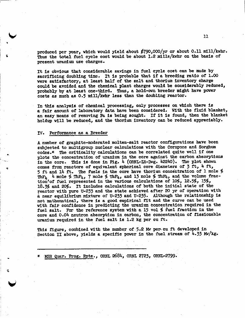
A number of graphite-moderated molten-salt reactor configurations have been sub3ected t o multigroup nuclear calculations with the Cornpone and Sorghum codes.* The c r i t i ca l i t y calculations can be correlated quite w e l l if one plots the concentration of uranium i n the core aminst the carbon absorptions in the core. This is done in Fig. 4 (ORNL-IR-Dwg. 42240). The plot shown comes from reactors of equivalent spherical core diameters of 3 f t , 4 f t , 5 ft and 14 ft. The fuels in the core have thorium concentration of 1 mole $ ThF4 4 mole $I mF4, 7 mole $I ThF'4, and 13 mole $ -4, and the volume frac- tion'of fuel represented in the various calculations of lo$, l2.5$, l5$, IS.$ and 20$. reactor with pure U-933 and the state achieved a f t e r 20 yr of operation with
Although the relationship is not mathematical, there is a good empirical f i t and the curve can be used with fair confidence in predicting the uranium concentration required in the fuel salt. For the reference system with a 15 vol $ fuel fraction in the core and 0.04 neutron absorption in carbon, the concentration of fissionable uranium required in the fuel salt is 1.2 kg per cu ft .
This Figure, combined with the number of 5.2 Mw per. cu ft developed in Section I1 above, yields ra specific power in the fuel stream of 4.33 Mw/kg.
It includes calculations of both the initial state of the
near equilibrium mixture of U-233 and U-235.
*
c Y
w

12
The chemical processing and blanket holdups of fuel lead t o a to t a l fission- able uranium Inventory of 845 kg, aa described In Section 111, 60 that the over-all specific power l a 2.96 Mw(th)/kg.
The effective value of eta for the fuel mixture w i l l depend on the thermality of the s p e c t m , which i L a related also t o the carbon absorptions per absorption i n fiselonable uranium. A t 0,Ok absorgption In carbon, the value of eta for the isotope mixture I s about 2.22, based on a thermal value of 2.28 for U-233.
Frarm the nuclear calpulatlons alted above, one can correlate the neutron absorp- tions in the done i n Mg. comprised of tions i n the
AB described provides for
carPier salt i n the core with the absorptions In carbon. 5 OFOTL-LR-Dwg. 42239). %e volume fraction of" carrier salt i s 20$, 15 i for the fuel and 55 for the f e r t i l e stream, so that the absorp- carrier salt i n the core are 0.04 for carbon abeorption of 0.04.
This I s
i n the preceang section, the reference chemical processing plant keeping the variable fpiision-product poison m e t i o n down t o 0.01,
and the Pa losses (5 x absorptiona) duwn ti 0.0L -upanirpn-236 will, of course; build up from radiative captures in U-235. With a breeaing ra t io of 1.06, the removal of U-236 by the sal& of excew me1 w911 approximately equal the removal by neutron abgiorptions, so that the U-236 poison wi l l be approximately O o O l 0 The neutron losses t o saturable non-volatile fission products w i l l be about 0.006, and i f Xe-135 losses can be kept t o 0,004, the to t a l saturable fission-product l06SSS w i l l be limited t o OoOlO To keep the Xe-135 losses t o 0.004 requires its removal on a time cycle of about 6 minuteroo The off-gas system ean be desfgned t o accom- plish this by bypassing 2$ of the p'mrr, flow through a degasser, degassing bypass f low i n the ART pumpo
This was the
Other neutron losses are estimated t o be 0.03 i n the blanket salt, O.OO3 for delayed neutrons, and 0,002 for l e d g e . fluoride vola t i l i ty process, O.OO5 may be adequate for chemical processing losses. soak np.c'Qe5$ by volume of fuel, gives a negligible loss unless there is pre- ferential ?%eeion-product absorption,
Conroiderfng the efficiency of the
Ffssion-product pickup by the graphite, assuming that the fuel tubes
The t o t a l neutron losses now add up t o about 0.16, which subtracted *om an eta of 2.22 fields a net breeding r a t io of 1.06. higher breeding rat ios can be obtained by decreasing the volume fraction of fuel i n the core and by increasing the uranium-to-carbon ra t io i n the core. However, these both lead t o bigher uranium inventories and consequently no great inrprovement, i f any, i n doubling time. Frrrthermore, i f thermal eta for U-233 I s 9.29, as is believed i n Oak Ridge, instead of the 2,28 assumed, the breeding ra t io is improved by nearly one point. With an over-all breeding ra t io of lo&, the doubling t i m e is about 13 yr of full-power operation.
It should be noted that
V. Feasibility and Cost of Mdten-Salt Reactors
The basic f eas ib iu ty of md.ten-salt reactors has been discussed in a seetion of the book wFluid Fuel ReBcctorigOo This and later information have been

... 'z
reviewed by the Fluid Fuel Reactors Task Force, and it was the concensus of the group that, with minor exceptions, the feasibi l i ty of the molten-salt reactor was established as far as materials compatibility and handling is concerned,
These exceptions concern the pickup of fuel salt by the graphite and the possible precipitation of U@ by gases adsorbed on the graphite. Since the time the Fluid Fuels Task Force met, the results of a one-year circulating salt loop containing graphite and of graphite Impregnation studiee have shown that the graphite i s stable i n contact vith the salt, an8 that there are varieties of graphite that w i l l soak up less than Oo2$ by volume of fuel ea l t , ble t o prevent U@ precipitation by pretreatment of the graphite*
It has also been found possi-
The Fluid Fuel Reactors !Pask Force further expressed doubt as t o the economic maintenance of f luid fuel reactors i n general. this can be answered f inal ly only i n a reactor experiment, which has been pro- posed, tenance procedures for one type of reactor construction.
For the molten-salt reactor,
In the meantime, good progress has been made i n devising suitable main-
Since the time of the task force, the design effor t on molten-salt reactors ha6 been directed towardbreeder reactors that take advantage of the compactness - that is possible as a result of the high temperature and good heat transfer pro- perties of molten salts. Most of the designs developed have a compact primary system, such as t h a t described in Appendix I and illustrated i n Fig. 60 these designs, the entire primary fuel c i rcui t is contained inside a reactor vessel. With this construction, a parallel connparison with solid-fuel-element reactors is evident, i n which the tubes of the primary heat exchangers of the salt reactor are compared t o the fuel tubes i n the core of a solid-fuel-element reactor; both contain fuel, both constitute the primary heat exchanger surface, and i n each case they are contained within the primary reactor vessel enclosure, In a similar way, the punrps for circulating the fuel are compared t o the control rod mechanisms (and fuel shuffling mechanfsm for the fast reactor). movSng parts inside the reactor enclosure, and the pump, though bulky,' is cer- tainly simpler. by overhead withdrau%land replacement, and the operations required are comparable t o those required for the replacement of core assemblies and repair of control mechanisms i n the reactors with sol id fuel elennentEi, particularly those cooled with sodiumo t o be higher than, say, for the fast reactor.
As for capital costs, the! higher temperature of the heat source and the very . Ugh heat capacity per uni t volume of the salt (approximately 4.4 times that of sodium) lead t o compactness of the entire system, The following table com- pares pertinent factors of complexity and heat transfer with four reactors using a sodium coolant. Comparing the ljeSlR primary heat exchanger with the reactor cores, it is simpler by vfrtue of having fewer tubes, and has about the same efffciency as the fast reactors i n terms of surface &rea.
%e avoidance of an intemedfate heat exehanger for the MSR, possible because there is no violent water reactton and because the fnduced radioactivity is very short Uvedj is a further factor reducing capital .cost ,
In
Both involve
bbintenance of pump and heat exchgager i n the salt system is
There is thus no reason t o expect maintenance costs for the WR
In the steam

14 L.i
Y generator portion, the higher temperature of the salt coolant gives an. advantage by about a factor of two.
The last two rows of the table indicate how the high heat capacity of the salt, even using a conservative bulk &P, can reduce the pump capacity and system piping requirements by at least a factor of two.
On the basis of this analysis, even after allowing for the high cost of INOR-8 and of the salt coolant, the capital costs of a molten-salt reactor should be less than for the sodium-cooled reactors.
Net e lectr ical IW assumed for reactor 333
Sodfum-Cooled Reactors Advanced
Fuel tubes per W E Primary heat exchanger tubes per MrJE 19
Primary heat transfer 22 surface per MwE (leuel tubes i n case of eodium- cooled reactors) sq f't per MWE
Intermediate heat exchanger - sq ft per N E
Steam generator, super- 120 heater and reheater
,surface sq f t per MwE
coolant flow data (avg) Bulk hT assumed 150°F gal /dn f low per MWE 106
80 205 94 283
58 28 140 264
111 38 14,6 25
93 170 160
237 214 345
92 200
338OF 275OF 250°F 350°P 241 6 3 318 214
* So WYY e t al, "Advanced Design of a Sodium-Cooled Thermal Reactor for Power Generatton", 1958 Geneva Conference Paper ~/604.

aj
, 5
The most careful cost estimates of molten-salt reactor construction b v e been made by 0. Do Whitman and are included in: CF-59-1-26; and (3) ORIVL 2796. The three cases include two power reactors of 640- and 860-Mw (thermal) capacity, and an experimental reactor of 30-Mw capacity.* A reasonable extrapolation of these costs t o the 2500-Mw (thermal) station required for lo00 W(E) yields capital costs of from $170 t o $200 per kw. This estimate I s for a first plant, but does not include developnent costs. When these capital costs are combined with the fuel cycle costs esti- mated I n Section I11 of 1,2 Mw/hhr and a reasonable operation and mainten- ance estimate of 1 mill /hhr, one gets a power cost i n the neighborhood of 6 mills/kwhr for the first such large breeder reactor plant. could expect lower costs than this as a result of prior prototype reactor construction and operation, It is diff icul t t o attempt t o predict ultimate costs, however, until experience has been had with at least an experimental reactor-
(1) ORnn 2634; (2) ORKL-
Presumably one
*

16
A P P E N D I X I.
INTRA-LABoRAToKy CORRESPONDENCE Oak Rim National Iaboratory
October 22, 1959
To: H. G. McPherson
cc: L. G. Alexander J. W. Miller File (BWK)
Subject: Volumes and Pressure Drops for Molten Salt Breeder Reactors
- The following table is a comparison of two reactor sizes, each with two flow velocities i n the external piping.
The heat exchanger has been designed on the basis of 0.300 in. inside diameter x 0.035 in. w a l l tubing i n a 45O helix, with adjacent coils wound opposite hand. Fuel temperatures are taken as 1275 and 1075OF; coolant temperatures as 1150 and 100O0F. exchanger length by 21$, increase the number of tubes by 5 6 , and increase the, diameter by about 15s. by about 16, which might overweigh the problems introduced by the other changes.
The use of 114 in. I D x 5/16 in. OD tubing would decrease the heat
The fuel volume external t o the core would be reduced
The fuel volume might be reduced by considering the entire f low in the center of the heat exchanger as "pump suction" and using a fiigher flow velocity. be about 1% of the fuel outsiae the core for the higher flow rate cases.
The attached sketch (Mg. 6) is approxh te ly t o scale for the smaller reactor with 20 ft per second fuel iteloeity i n tb& piping.
This would
:nh Enclosur€?
/s/ B. W. Kinyon
c
V

v o m s m PRESSURE D R O ~ FOR MOLTEN SALT BREEDER REACTORS
Reactor Power, MwE (net) Statton Efficiency,$ Reactor Power, MwT -&et mer, $ Core Power, MwT
333 40.85 815 8 750
1275 Fuel Temperature Exit, F Fuel Temperature Entrance, F 1075
200 55.2 3 m i n Fuel, OF
Volume low of Fuel, f t /sec
Plow Area, f t 2.765
0
Flow Velocity21n Core, f"t/sec 20
Volume Fraction in Core Core cross Section, f t 2 Core Diameter, f t Mameter of Eq valent Sphere, f t
Fuel volume i n Core, f t3
B l a n k e t Thickness, f t Blanket Volume, f t3 Cu Ft of B l a n k e t per M MUT per Cu Ft of B l a n k e t
Core Volume, f t 3
Fuel Velocity i n "piping", ft/sec Flow Area, f t Bat Exchanger Area, f't Bundle Area, f t2 Coolant Flow Area, ft Tbtal Area Bundle Height, f% Bundle I D , f t Bundle OD, ft Cartridge OD, f't
2 2
2
0.25 22.08 5.30 6.07 117 29 * 25
2.5 741 0 .gu> 1.10
2.92 TzxE 8.75 2 a 6 4,70 5.17
20
2."77 13.58 16.95
2.92 19 27 8.75 1 875 4.56 4.95
500 40.85 1223 8 1125
1275 1075 200 82.8 20 4.140
0.25 33.3-2 6.50 7.45 215 53.75
2.5 918 0 750 1.333
4.38 9 - 2 5 8.75 2.65 5 073 6.20
-
20
4.14
4.36 zRm8 8 75' 2.29 5.58 6.06
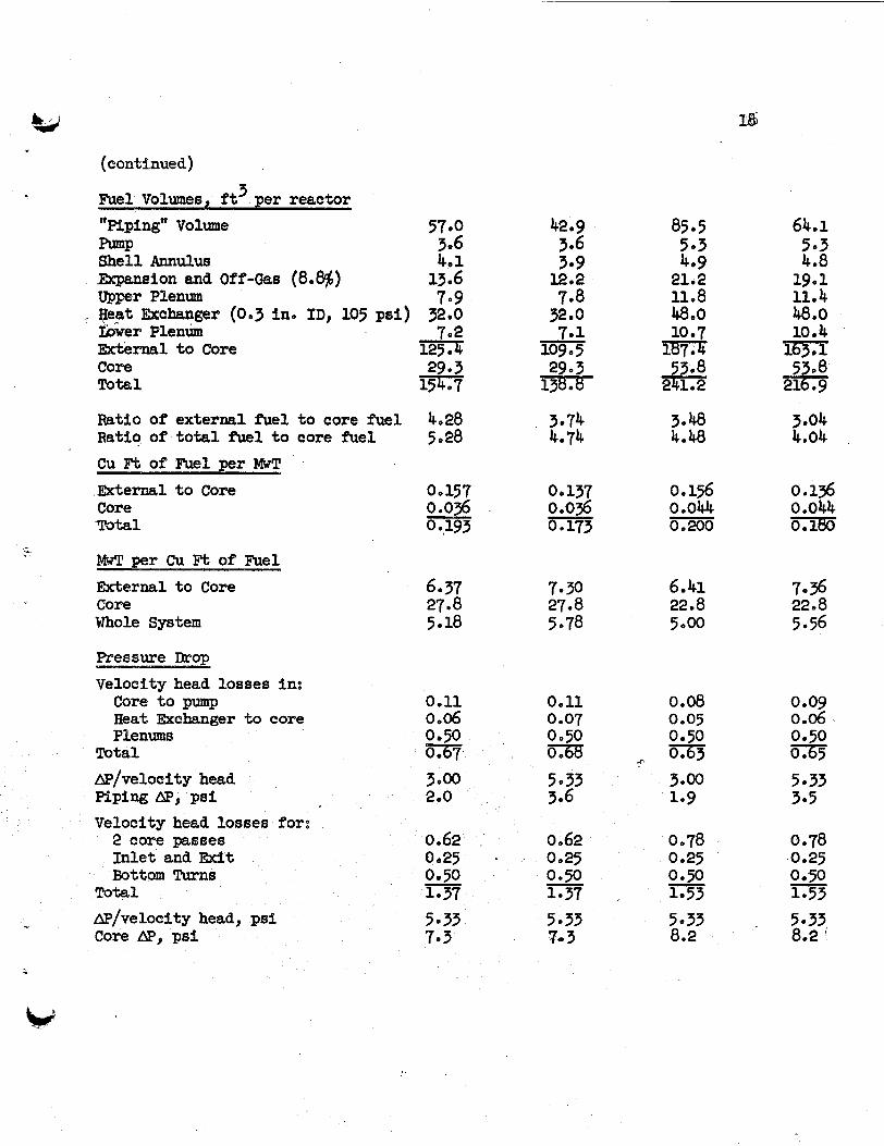
(eontfnued)
~ u e l volumes, f i 3 per reactor
"Pdpfngw Vohme 57.0 -P 3.6 Shell Annulus 401 Bxpansion and Off-Gas (808$) 13.6 Upper Plenum 709 peat Exchanger (003 Ino I D , 105 psi) h e r Plenum
Core Tota l
32.0
External t o Core -&
Ratio of external fuel t o core fuel 4.28 Ratio of t o t a l fuel t o core f ie1 5028 cu FL of Fuel per MWT Externeel t o Core Core Total
MwT per Cu Ft of' Fuel External t o Core Core Whole System
6.37 27.8 5.18
Ppessupe Drop
Velocity head losses in: core t o pump 0.11 Heat Exchanger to core 0 0 0 6 Plenums 0.50
Total
&P/veloeity head 3000 MPfW @ o Psf 200 Velocfty head losses for:
2 core passes 0062 Inlet and E x i t 0.25 Bottom Turns 0.50
Total - 1.37
AP/velocity head, psf 5.33 Core mp ps i 7.3
7.30 27.8 5.78
0.11 0.07 0.50 m 5033 3.6
0.62 0.25 0.50 1.37 5.33 7* 3
-
85 0 5
503 409
21.2 11.8 4800 10.7 ls?.4
53.8 241,2
3048 4.48
0 . 156 0 0044 0.200 -
6.41 22.8 5 . 0
0.08 0.05 0.50
3.00 109
0078 0.25 0.50 1.53 5033 8.2
4- Oa-63
-
64,1 5 .3 4.8 19.1
48.0
163.1 53.8
216.9
1104
10.4
3.04 4.04
0.136 0.044 K i m
7.36 22.8 5.56
0.09 0 006 0.50 0165 5.33 3.5
0.78 0.25
1-53 5.33 8.2
0050 -

(continued)
.
Total Pressure Drop Outside
Fresipe mop Across Heat
Total AP i n System, psi
Hea%.JZxchanger, psi
Exoknger, psi
i
9.3 10.9 10.1
105 - 115 e 1
‘ . V , . .
11.7
105 .o 116.7 -

G
BLANKE INLE
U M C L A S S I FIE0 O R N L - L R - D W G . 42242
BLANKET "31
RAPHITE SEAL 0
T T
T IR
c
H ITE TO METAL
fD 0
Figure 1

21 UNCLASSIFIED
ORNL- LR-DWG 37258
Fig. 2 Heterogeneous, Graphite - Moderated, Two- Region, Molten - Salt, Thorium Breeder.

22
ORNLLR-DWG 44463 UNCLASSImD
.-> SALT
GRAPHITE REFLECTOR'
(COOLED B Y 6 L A N K E T
S ALT 1
~ BLANKET
-TO FUEL E X I T
GRAPHITE MODERATOR
GRAPHITE T U B E S
BRAZED J GRAPHITE
OINTS, TO INOR-8
Fig. 3. I n t e r n a l l y C o o l e d R e a c t o r

W
0 0
a
LL 0
M c YI
a a W
z 3 z a a 3
W
m a z 0 u, u, - ii CI, Y
t
0.70
0.50
0.30
0.20
0 . i O
0.07
23
U N C L A S S IF1 E D ORNL-LR-DWG. 42240
I I I
I
0. 0.4 0.02 0.03 0.05 0.07
I ABSORBTION IN U - 2 3 3 + U-235 NEUTRON ABSORBTIONS IN CARBON PER
FUEL CONCENTRATION IN CORE VS. C A R B O N ABSORBTIONS
0.10
Figure 4

24
i
W
w
a W U U
0
- a
v) z 0 I- m a 0 v) ai a
0
o x
0.07
0.05
0.03
0.02
0.0 i
UN C L A S S I FI ED O R N L - L R - DWG. 42239
0.0 i o 0.02 0.03 0.05 ABSORBTJONS IN CARBON
Figure 5
T 0.07 0.i 0

M OLTEN SALT BREEDER REACTOR Figure 6

Y
6
t
Mstpibution
1-15. Ho Go WcPherson 16. L. G~ Alexander l T O Co Jo Baston 18, A. L~ Benson, AEC-ORQ
20, Fo Fo Blankemhip 19. E o S o Bet t i6
210 A o L o BoCh 220 W o Fa BoUdreaU
240 Re Bo Brig@ 250 W o Ep Brawaiw
23. Eo Jo Breeding
26, D. 0. Campbell 27. W e H o Carr 280 W. L. carter 290 Go Io Cathers
31, Re A. Charpie 32. Ro Ro Coveyoa
34, We K. Ergen
36. Wo Re G a l l 370 W O RO Grimes
30. R0.H. Cham
330 D o A o DO~glas
350 A o P o maas
38. Jo P. EEumnond
40, Wo Ho Jordan 41. P. R. Kasten 42. Go Wo Keilholtz 43. Wo E. Wnney 4.4, Bo Wo Kinyon 450 M e EO Zaclcey 46, J. A. Iane
390 H o W e Hoffman
47. 4 8 0 490 500 51, 52. 53. 54. 55 0
56 0
57. 58. 590 60 . 61 62 639 64, 65 0
6 6 0 67. 68, 69. 700 710 72 73 740 75 0
76-77. 78-92
R. N. won W o Do bWly E o R o Man L o A* Mann W o B o MCmmld Ho Jo Metz R. Po Milford A. Jo MLller Jo W. Miller
Co W. Restor W. R. Oeiborn A. Mo Perry Ro Mo Pierce J. To Roberts Ho W. Savage Fo Po Self Mo Jo Skinner
G o J o NeSSle
J. A o Swartout A o T a b O a d a R o Eo Th- Do Bo -auger Fo Co VonderIage
A. Mo Weinberg Jo Ho Westsik
Jo Zasler
Laboratory Record6
G o M o Watson
G o D o Whitman
Labomtory Records 3 R o C
TISE-LEK!