ceti | shamu · project planning verification and validation ceti | shamu critical design review...
TRANSCRIPT

Critical Project Elements
Purpose/Objectives Design Solution Project RisksRequirements Satisfaction
Project PlanningVerification and
Validation
CETI | SHAMUCritical Design Review
Cetacean Echolocation Translation Initiative
Search and Help Aquatic Mammals UAS
Team
Ian Barrett
Grant Dunbar
George Duong
Jesse Holton
Sam Kelly
Lauren McIntire
Benjamin Mellinkoff
Justin Norman
Severyn Polakiewicz
Michael Shannon
Brandon Sundahl
Customers
Jean Koster
James Nestor
David Gruber
Advisor
Donna Gerren

Critical Project Elements
Purpose/Objectives Design Solution Project RisksRequirements Satisfaction
Project PlanningVerification and
ValidationPurpose/Objectives
Project Description
Search and Help Aquatic Mammals UAS
will design an unmanned aerial system to carry a
future instrument payload capable of locating
sperm whales in the ocean. The future unmanned
aerial vehicle will be launched and recovered from
a research vessel’s helipad.
2

Critical Project Elements
Purpose/Objectives Design Solution Project RisksRequirements Satisfaction
Project PlanningVerification and
ValidationPurpose/Objectives
Multi-Year User CONOPS
3
8 9

Critical Project Elements
Purpose/Objectives Design Solution Project RisksRequirements Satisfaction
Project PlanningVerification and
ValidationPurpose/Objectives
SHAMU Test CONOPS
4
Battery 7
8

Critical Project Elements
Purpose/Objectives Design Solution Project RisksRequirements Satisfaction
Project PlanningVerification and
ValidationPurpose/Objectives
Functional Requirements
1. Operate in manually piloted mode throughout all phases of flight with
autonomous mode capability at cruise altitude.
2. Takeoff and land from/to a stationary 9.1 m x 9.1 m platform obstructed
fore (represents ship superstructure) and aft (represents ship crane).
3. 12 km communication range for telemetry, images, and RC control from
ground control station.
5

Critical Project Elements
Purpose/Objectives Design Solution Project RisksRequirements Satisfaction
Project PlanningVerification and
ValidationPurpose/Objectives
Functional Requirements
4. Aircraft shall support downward-facing 2.0 kg simulated instrument
payload with 15 cm x 15 cm x 23 cm dimensions.
5. Aircraft shall be operable and recoverable onto stationary platform in
winds up to 10 m/s.
6. Aircraft shall have 100 km ground track range endurance.
6

Critical Project Elements
Purpose/Objectives Design Solution Project RisksRequirements Satisfaction
Project PlanningVerification and
ValidationDesign Solutions
Design Solutions
7

Critical Project Elements
Purpose/Objectives Design Solution Project RisksRequirements Satisfaction
Project PlanningVerification and
ValidationDesign Solutions
Design Solutions
Aircraft Takeoff Recovery AutopilotFlight
ComputerRF Comm. Electronics
Design and
Validate
Airframe
Bungee
Launch
with Rail
Net with
Extending
Lines
PX4 Pro
with
Pixhawk
2.1
Raspberry Pi
3 Model B
RFD900+
Datalink
OpenLRS
RC
Component
List
8

Critical Project Elements
Purpose/Objectives Design Solution Project RisksRequirements Satisfaction
Project PlanningVerification and
ValidationDesign Solutions
Functional Block Diagram
9

Critical Project Elements
Purpose/Objectives Design Solution Project RisksRequirements Satisfaction
Project PlanningVerification and
ValidationDesign Solutions
Design Solution
Aircraft Takeoff Recovery AutopilotFlight
ComputerRF Comm. Electronics
Design and
Validate
Airframe
Bungee
Launch
with Rail
Net with
Extending
Lines
PX4 Pro
with
Pixhawk
2.1
Raspberry Pi
3 Model B
RFD900+
Datalink
OpenLRS
RC
Component
List
10

Critical Project Elements
Purpose/Objectives Design Solution Project RisksRequirements Satisfaction
Project PlanningVerification and
ValidationDesign Solutions
Aircraft Design: Specifications
Wing Span 3.0 m (10 ft)
Length 1.4 m (4.5 ft)
Height 0.53 m (1.8 ft)
Wing Area 0.93 m2 (10 ft2)
Wing Aspect Ratio 10
Empty Weight 4.5 kg (10 lbs)
Payload Weight 2.0 kg (4.4 lbs)
Gross Weight 8.45 kg (19 lbs)
Motor Power 1300 W (1.74 hp)
11
Three Views of the SHAMU UAV

Critical Project Elements
Purpose/Objectives Design Solution Project RisksRequirements Satisfaction
Project PlanningVerification and
ValidationDesign Solutions
Aircraft Design: Performance
Cruise Speed 20 m/s (38 kts)
Stall Speed 11 m/s (20 kts)
Range 100 km (62 mi)
Climb Rate >5.1 m/s (>1000 ft/min)
Cruise L/D 12 - 16.2
Wing Loading 9.8 kg/m2 (2.0 lbs/ft2)
12
Three Views of the SHAMU UAV

Critical Project Elements
Purpose/Objectives Design Solution Project RisksRequirements Satisfaction
Project PlanningVerification and
ValidationDesign Solutions
Aircraft Design
13
Material Selection
● Expanded polypropylene wing/fuselage
core
● G10 fiberglass bulkheads
● S-fiberglass/epoxy fuselage covering
● 5 mm CP film wing covering
● Carbon fiber spar in each wing half,
aluminum 7075 carry-through spar
● Winglets attached with N52 neodymium
magnets, reinforced with carbon strip
● Folding pusher prop to accommodate
dolly configurationSolidWorks Rendering of SHAMU Aircraft

Critical Project Elements
Purpose/Objectives Design Solution Project RisksRequirements Satisfaction
Project PlanningVerification and
ValidationDesign Solutions
Design Solution
Aircraft Takeoff Recovery AutopilotFlight
ComputerRF Comm. Electronics
Design and
Validate
Airframe
Bungee
Launch
with Rail
Net with
Extending
Lines
PX4 Pro
with
Pixhawk
2.1
Raspberry Pi
3 Model B
RFD900+
Datalink
OpenLRS
RC
Component
List
14

Critical Project Elements
Purpose/Objectives Design Solution Project RisksRequirements Satisfaction
Project PlanningVerification and
ValidationDesign Solutions
Takeoff Design Overview
15
Bungees 5
Initial length of Bungee 1.99 m
Spring Constant 86 N/m
Tension Force 343.33 N
Final Velocity 13.2 m/s
Rail Length 5.25 m
PVC Diameter 2”
Takeoff Angle 5 degrees
Max Deflection of Rails 3.86 mm
Time 0.69 s
SHAMU UAV, Dolley, and Launch Ramp
Dolley (Front)
Dolley
Model
(Side)

Critical Project Elements
Purpose/Objectives Design Solution Project RisksRequirements Satisfaction
Project PlanningVerification and
ValidationDesign Solutions
Design Solution
Aircraft Takeoff Recovery AutopilotFlight
ComputerRF Comm. Electronics
Design and
Validate
Airframe
Bungee
Launch
with Rail
Net with
Extending
Lines
PX4 Pro
with
Pixhawk
2.1
Raspberry Pi
3 Model B
RFD900+
Datalink
OpenLRS
RC
Component
List
16

Critical Project Elements
Purpose/Objectives Design Solution Project RisksRequirements Satisfaction
Project PlanningVerification and
ValidationDesign Solutions
Recovery System● Net suspended between two poles
● Pulley connections to extend upon impact
● Extension of net reduces forces upon
landing and closes the net to capture
aircraft
● Impact forces are damped by a bungee
attached to the pulley line
● Sailing Cleat prevents line from rebounding
● Hook on nose of aircraft will catch the net to
prevent impact with ground
17
7.6 m
5 m
Net Front View
Isometric Back
View
3 m

Critical Project Elements
Purpose/Objectives Design Solution Project RisksRequirements Satisfaction
Project PlanningVerification and
ValidationDesign Solutions
Design Solution
Aircraft Takeoff Recovery AutopilotFlight
ComputerRF Comm. Electronics
Design and
Validate
Airframe
Bungee
Launch
with Rail
Net with
Extending
Lines
Pixhawk 2.1
with PX4-
Pro
Raspberry Pi
3 Model B
RFD900+
Datalink
OpenLRS
RC
Component
List
18

Critical Project Elements
Purpose/Objectives Design Solution Project RisksRequirements Satisfaction
Project PlanningVerification and
ValidationDesign Solutions
Navigation Hardware/Software Design
19

Critical Project Elements
Purpose/Objectives Design Solution Project RisksRequirements Satisfaction
Project PlanningVerification and
ValidationDesign Solutions
Design Solution
Aircraft Takeoff Recovery AutopilotFlight
ComputerRF Comm. Electronics
Design and
Validate
Airframe
Bungee
Launch
with Rail
Net with
Extending
Lines
PX4 Pro
with
Pixhawk
2.1
Raspberry Pi
3 Model B
RFD900+
Datalink
OpenLRS
RC
Component
List
20

Critical Project Elements
Purpose/Objectives Design Solution Project RisksRequirements Satisfaction
Project PlanningVerification and
ValidationDesign Solutions 21
Electronic Components
Battery* Tattu 22000mah 6S Li-po Battery Camera* Raspberry Pi Camera
Module
Motor* Propdrive 5060 v2 380kV
Brushless Motor
Flight Controller Pixhawk 2.1 Autopilot
Speed Controller Turnigy Plush 100A Speed
Controller w/ 5V UBEC
Plane Radio Receiver OrangeRx Open LRS
433MHz 9Ch Receiver
Servos HK15298B High Voltage Coreless
Digital MG/BB Servo
Ground Station Transmitter OrangeRx Open LRS
433MHz Transmitter 1W
GPS Here+ GNSS GPS for Pixhawk
2.1
Telemetry Radio RFD 900+
Airspeed Sensor PX4 Airspeed Sensor w/ Pitot
Tube
R/C Controller Turnigy 9XR PRO Radio
Transmitter Mode 2 w/o
Module
Sensor Board and BEC MAUCH PL-100A Sensor Board
and PL 2-6S BEC w/ 2 5V
Outputs

Critical Project Elements
Purpose/Objectives Design Solution Project RisksRequirements Satisfaction
Project PlanningVerification and
ValidationDesign Solutions
Critical Project Elements
22

Critical Project Elements
Purpose/Objectives Design Solution Project RisksRequirements Satisfaction
Project PlanningVerification and
ValidationCritical Project
Elements
Critical Project Elements
23
Aerial Vehicle Design
● Stability and control
● Future sensor payload
● Tradeoff between maximizing lift-to-drag ratio and
structural/manufacturing complexity
Takeoff and Recovery● Accelerate/decelerate aircraft under maximum structural load
● Capability to transport and setup on 9.1m x 9.1m helipad
CPE Requirement Considerations

Critical Project Elements
Purpose/Objectives Design Solution Project RisksRequirements Satisfaction
Project PlanningVerification and
ValidationCritical Project
Elements
Critical Project Elements
24
Communication with
Ground Station
● Communication range of 12 km from ground station
● Transmit images at one per minute
● Piloted manual control
● Transmit updated flight waypoints
● Transmit telemetry to ground station
Flight Computer / Autopilot● Collects sensor data for virtual cockpit
● Autopilot keeps aircraft in steady, level flight
● Accepts flight waypoints and executes
CPE Requirement Considerations

Critical Project Elements
Purpose/Objectives Design Solution Project RisksRequirements Satisfaction
Project PlanningVerification and
ValidationRequirements Satisfaction
Design Requirements Satisfaction
25

Critical Project Elements
Purpose/Objectives Design Solution Project RisksRequirements Satisfaction
Project PlanningVerification and
ValidationRequirements Satisfaction
Airframe & Powerplant
26

Critical Project Elements
Purpose/Objectives Design Solution Project RisksRequirements Satisfaction
Project PlanningVerification and
ValidationRequirements Satisfaction
CPE: Aerial Vehicle Design Key Requirements
27
FR 2 Takeoff and land from/to a stationary 9.1 m x 9.1 m platform obstructed fore (represents ship
superstructure) and aft (represents ship crane).
DR 2.1 The aircraft shall have a nose hook that sustains 5 g net recovery forces.
DR 2.2 The aircraft wings shall sustain 5 g forces for maneuvers and net recovery.
FR 4 Aircraft supports downward-facing 2.0 kg simulated instrument payload with 15 cm x 15 cm x 23 cm
dimensions.
FR 1 The aircraft shall operate in remotely piloted and fully autonomous modes throughout all phases of
flight.
DR 1.1 The aircraft shall have static longitudinal stability.
DR 1.2 The control system shall provide required control surface deflections for aircraft longitudinal and lateral
stability throughout all phases of flight.

Critical Project Elements
Purpose/Objectives Design Solution Project RisksRequirements Satisfaction
Project PlanningVerification and
ValidationRequirements Satisfaction
CPE: Aerial Vehicle Design Key Requirements
28
FR 6 The aircraft shall have a 100 km ground track range.
DR 6.1 The aircraft shall have a lift-to-drag ratio of 12.
DR 6.2 Battery shall have 1.4 hr endurance

Critical Project Elements
Purpose/Objectives Design Solution Project RisksRequirements Satisfaction
Project PlanningVerification and
ValidationRequirements Satisfaction
CPE: Aerial Vehicle Design Key Requirements
29
FR 4 Aircraft supports downward-facing 2.0 kg simulated instrument payload with 15 cm x 15 cm x 23 cm
dimensions.
Downward facing
RPi Cam mount
∴ FR 4 Satisfied22.9 cm
15.2 cm
11.0 cm

Critical Project Elements
Purpose/Objectives Design Solution Project RisksRequirements Satisfaction
Project PlanningVerification and
ValidationRequirements Satisfaction
CPE: Aerial Vehicle Design Key Requirements
30
● Aerodynamic center: 71.75 cm behind the
nose
○ Including wing and fuselage effects
● Center of gravity w/ 2 kg payload: 64.93 cm
behind the nose
● Static Margin: 22.4% (6.82 cm)
DR 1.1 The aircraft shall have static longitudinal stability.
C.G.
∴ DR 1.1 Satisfied
A.C.

Critical Project Elements
Purpose/Objectives Design Solution Project RisksRequirements Satisfaction
Project PlanningVerification and
ValidationRequirements Satisfaction
CPE: Aerial Vehicle Design Requirements
31
Design choices to maximize L/D
● Wing covering to create smooth surface
● Fuselage covering to create smooth surface
● AVL, XFLR5, OpenVSP, X-Plane models all
predict an L/D > 12*
DR 6.1 The aircraft shall have a lift-to-drag ratio of 12.
∴ DR 6.1 Satisfied
* To be verified by L/D tests in half-scaleMATLAB L/D prediction

Critical Project Elements
Purpose/Objectives Design Solution Project RisksRequirements Satisfaction
Project PlanningVerification and
ValidationRequirements Satisfaction
CPE: Aerial Vehicle Design Requirements
Component Power Needed
Motor (Steady Flight) 277 Wh
Motor (Climb) 39.6 Wh
Pixhawk 1.75 Wh
RFD 900+ 5.6 Wh
OrangeRX Open LRS 0.28 Wh
Raspberry 𝞹 w/ Camera 2.45 Wh
Servo 14 Wh
Total Required Energy: 375 Wh
32
Tattu 22000mAh 6S 25C 22.2V Lipo Battery PackCapacity: 22000 mAh
Voltage: 22.V
Watt-hours: 488 Wh
Available Energy: 390 Wh
Weight: 2.65 kg
DR 6.2 Battery shall have 1.4 hr endurance
390 Wh > 375 Wh
∴ DR 6.2 is satisfied
Selected Battery Pack

Critical Project Elements
Purpose/Objectives Design Solution Project RisksRequirements Satisfaction
Project PlanningVerification and
ValidationRequirements Satisfaction
33
DR 2.1 The aircraft shall have a nose hook that sustains 5 g landing forces.
CPE: Aerial Vehicle Design Key Requirements
One hook prong under 5 g
must sustain
Bending Moment : 37 Nm
For a (32mm x 96mm rectangular prong)
Internal Stress : 766 MPa
Solution
Titanium Grade S Tensile Strength : 880 MPa > 766 MPa
Initial proof-of-concept tests show 88% success
rate (29 of 33) with potential for improvement
SolidWorks Rendering: Nose Hook and
Threaded Rod Through Nose Cone
Cap Nut
Four-Pronged
Hook
Threaded Rod
Hub
1.2 Safety Factor ∴ DR 2.1 Satisfied

Critical Project Elements
Purpose/Objectives Design Solution Project RisksRequirements Satisfaction
Project PlanningVerification and
ValidationRequirements Satisfaction
CPE: Aerial Vehicle Design Requirements
34
These rods connect the wings to the fuselage
and must sustain
Shear Force: 103.5 N
For a 3/16” diameter rod
Shear Stress: 5.65 MPa
Solution
Aluminum (6061) rod:
Shear Strength is 204 MPa
DR 2.2 The aircraft wings shall sustain 5 g forces for maneuvers and net recovery.
204 MPa > 5.65 MPa

Critical Project Elements
Purpose/Objectives Design Solution Project RisksRequirements Satisfaction
Project PlanningVerification and
ValidationRequirements Satisfaction
35
DR 2.2 The aircraft wings shall sustain 5 g forces for maneuvers and net recovery.
CPE: Aerial Vehicle Design Key Requirements
Wing Modelled as Cantilever Beam with Distributed Loading (5 g)
m
Wing spar must sustain
Bending Moment : 116 Nm
Shear Force : 169 N
For a (20mm x 18mm Tube)
Internal Stress : 430 MPa
Shear Stress : 2.8 MPa
Solution
Carbon Fiber: Tensile Strength is 650 MPa > 430 MPa
Shear Strength is 450 Mpa > 2.8 MPa
Aluminum (7075-T6) Carry Through (solid rod):
Tensile Strength is 500 MPa > 280 MPa
1.5 Safety Factor ∴ DR 2.2 SatisfiedSolidWorks Rendering: Carbon Spar Along
Quarter Chord
12” Internal
Aluminum
Carry Through

Critical Project Elements
Purpose/Objectives Design Solution Project RisksRequirements Satisfaction
Project PlanningVerification and
ValidationRequirements Satisfaction
CPE: Aerial Vehicle Design Key Requirements
36
Controllability:
● A & B state space
matrices calculated
● Longitudinal & Lateral
Controllability matrix
○ Full rank
DR 1.2 Satisfied
System is controllable:
Elevons (deflection) allows for
modification of poles (eigenvalues)
for desired stability
DR 1.2 The control system shall provide required control surface deflections for aircraft longitudinal and lateral
stability throughout all phases of autonomous flight.
Controllability Matrices

Critical Project Elements
Purpose/Objectives Design Solution Project RisksRequirements Satisfaction
Project PlanningVerification and
ValidationRequirements Satisfaction
CPE: Aerial Vehicle Design Key Requirements Recap
37
FR 2 Takeoff and land from/to a stationary 9.1 m x 9.1 m platform obstructed fore (represents ship
superstructure) and aft (represents ship crane).
DR 2.1 The aircraft shall have a nose hook that sustains 5 g landing forces.
DR 2.2 The aircraft wings shall sustain 5g landing forces.
FR 4 Aircraft supports downward-facing 2.0 kg simulated instrument payload with 15 cm x 15 cm x 23 cm
dimensions.
FR 1 The aircraft shall operate in remotely piloted and fully autonomous modes throughout all phases of
flight.
DR 1.1 The control system shall provide required control surface deflections for aircraft longitudinal and lateral
stability throughout all phases of flight.
DR 1.2 The control system shall provide required control surface deflections for aircraft longitudinal and lateral
stability throughout all phases of flight.

Critical Project Elements
Purpose/Objectives Design Solution Project RisksRequirements Satisfaction
Project PlanningVerification and
ValidationRequirements Satisfaction
CPE: Aerial Vehicle Design Key Requirements Recap
38
FR 6 The aircraft shall have a 100 km ground track range.
DR 6.1 The aircraft shall have a lift-to-drag ratio of 12.
DR 6.2 Battery shall have a 1.4 hr endurance

Critical Project Elements
Purpose/Objectives Design Solution Project RisksRequirements Satisfaction
Project PlanningVerification and
ValidationRequirements Satisfaction
Launch System
39

Critical Project Elements
Purpose/Objectives Design Solution Project RisksRequirements Satisfaction
Project PlanningVerification and
ValidationRequirements Satisfaction
CPE: Launch Design Key Requirements
40
FR 2 Takeoff and land from/to a stationary 9.1 m x 9.1 m platform obstructed fore (represents ship
superstructure) and aft (represents ship crane).
DR 2.1 The launch system shall accelerate the UAV to 13.2 m/s by the end of ramp.
DR 2.2 The launch system shall launch the UAV under 5 g.

Critical Project Elements
Purpose/Objectives Design Solution Project RisksRequirements Satisfaction
Project PlanningVerification and
ValidationRequirements Satisfaction
41
FR 2 Takeoff and land from/to a stationary 9.1 m x 9.1 m platform obstructed fore (represents ship
superstructure) and aft (represents ship crane).
CPE: Launch Design Key Requirements
● Rail system length: 5.8 m
● Rail system width: 2.4 m
● Bungee anchor position forward
of rail system: 1.0 m
Total length < 9.1m
FR 2 Satisfied

Critical Project Elements
Purpose/Objectives Design Solution Project RisksRequirements Satisfaction
Project PlanningVerification and
ValidationRequirements Satisfaction
42
CPE: Launch Design Key Requirements
Concerns:
G-force on launch needs to be < 5 g
UAV/Cradle speed ≥13.2 m/s by end of ramp (5.25 m)
Solution:
Acceleration spread out across a long ramp
Assumptions:
Newton’s 1st law
Mass of UAV/Cradle is 14.0 kg
Results:
UAV/Cradle speed of 13.2 m/s at 4 m < 5.25 m
UAV/Cradle experiences 1.90 g
DR 2.1 The launch system shall accelerate the UAV to 13.2 m/s by the end of ramp.
DR 2.2 The launch system shall launch the UAV under 5 g.
∴ DR2.1, DR 2.2 Satisfied

Critical Project Elements
Purpose/Objectives Design Solution Project RisksRequirements Satisfaction
Project PlanningVerification and
ValidationRequirements Satisfaction
CPE: Launch Design Key Requirements Recap
43
FR 2 Takeoff and land from/to a stationary 9.1 m x 9.1 m platform obstructed fore (represents ship
superstructure) and aft (represents ship crane).
DR 2.1 The launch system shall accelerate the UAV to 13.2 m/s by the end of ramp.
DR 2.2 The launch system shall launch the UAV under 5 g.

Critical Project Elements
Purpose/Objectives Design Solution Project RisksRequirements Satisfaction
Project PlanningVerification and
ValidationRequirements Satisfaction
Recovery System
44

Critical Project Elements
Purpose/Objectives Design Solution Project RisksRequirements Satisfaction
Project PlanningVerification and
ValidationRequirements Satisfaction
CPE: Recovery System Requirements
45
FR 2 Takeoff and land from/to a stationary 9.1 m x 9.1 m platform obstructed fore (represents ship
superstructure) and aft (represents ship crane).
DR 2.1 The recovery system shall exert forces on the aircraft under 5 g.
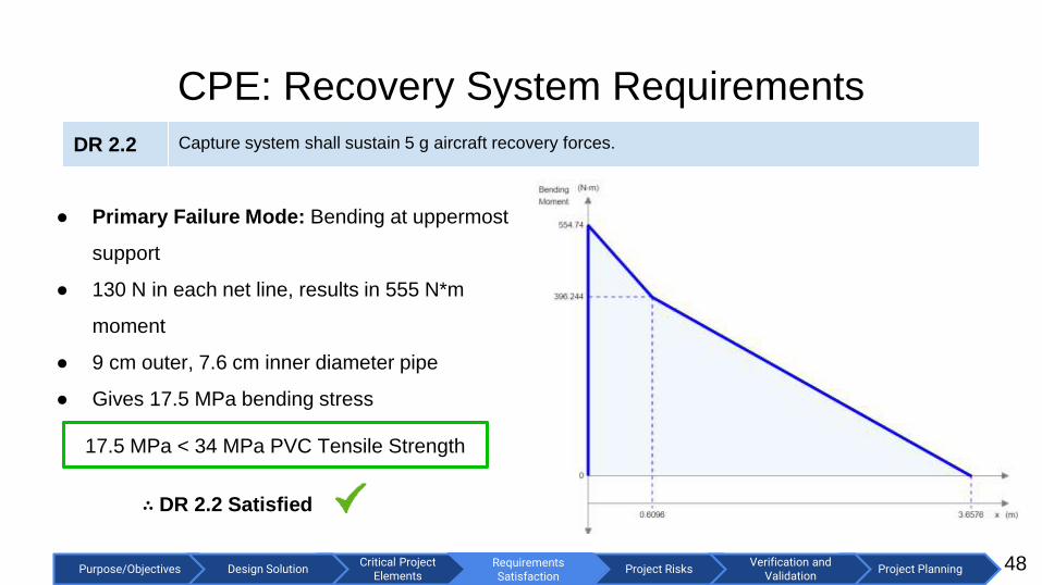
DR 2.2 Capture system shall sustain 5 g aircraft recovery forces.
Front View Side View Top View
7.6 m
5 m
3 m

Critical Project Elements
Purpose/Objectives Design Solution Project RisksRequirements Satisfaction
Project PlanningVerification and
ValidationRequirements Satisfaction
CPE: Recovery System Requirements
46
Details:
● Initial recovery KE 572 J (9.1 kg, 12 m/s)
● 2 bungees hold ½ of PE each
● Spring constant 118 N/m at 2.2 m stretch
● Selected bungee has 260 N force at 100%
extension
∴ FR 2 Satisfied
2.2 m extension results in
4.8m recovery distance < 9.1m helipad

Critical Project Elements
Purpose/Objectives Design Solution Project RisksRequirements Satisfaction
Project PlanningVerification and
ValidationRequirements Satisfaction
CPE: Recovery System Requirements
47
FR 2 Takeoff and land from/to a stationary 9.1 m x 9.1 m platform obstructed fore (represents
ship superstructure) and aft (represents ship crane).
DR 2.1 The recovery system shall exert forces on the aircraft under 5 g.
● Recovery System Dimensions:
7.6 m x 3.0 m < 9.1 m x 9.1 m
∴ FR 2 Satisfied
● Maximum Line Tension 130 N
● Maximum force on aircraft
395 N = 4.4 g < 5g
∴ DR 2.1 Satisfied
Critical Project Elements
Purpose/Objectives Design Solution Project RisksRequirements Satisfaction
Project PlanningVerification and
ValidationRequirements Satisfaction
CPE: Recovery System Requirements
48
● Primary Failure Mode: Bending at uppermost
support
● 130 N in each net line, results in 555 N*m
moment
● 9 cm outer, 7.6 cm inner diameter pipe
● Gives 17.5 MPa bending stress
17.5 MPa < 34 MPa PVC Tensile Strength
∴ DR 2.2 Satisfied
DR 2.2 Capture system shall sustain 5 g aircraft recovery forces.

Critical Project Elements
Purpose/Objectives Design Solution Project RisksRequirements Satisfaction
Project PlanningVerification and
ValidationRequirements Satisfaction
FR 2 Takeoff and land from/to a stationary 9.1 m x 9.1 m platform obstructed fore (represents ship
superstructure) and aft (represents ship crane).
DR 2.1 The recovery system shall exert forces on the aircraft under 5 g.
DR 2.2 Capture system shall sustain 5 g aircraft recovery forces.
CPE: Recovery System Requirements Recap
49
Critical Project Elements
Purpose/Objectives Design Solution Project RisksRequirements Satisfaction
Project PlanningVerification and
ValidationRequirements Satisfaction
Navigation &
Communication
50

Critical Project Elements
Purpose/Objectives Design Solution Project RisksRequirements Satisfaction
Project PlanningVerification and
ValidationRequirements Satisfaction
CPE: Nav/Comm Design Key Requirements
51
FR 1 Operate in manually piloted mode throughout all phases of flight with autonomous mode capability at
cruise altitude.
DR 1.1 Aircraft shall transmit telemetry to ground station.
DR 1.2 Ground control station shall provide virtual cockpit.
DR 1.3 Aircraft shall fly autonomous missions based on waypoints and loiter points.
DR 1.4 Mission shall be reprogrammable during flight.
FR 3 12 km communication range for telemetry, images, and RC control from ground control station.
DR 3.1 Telemetry radio shall have a range of 12 km at 90+ kbps.
DR 3.2 Aircraft shall capture and transmit images to ground station at 1/60 Hz.

Critical Project Elements
Purpose/Objectives Design Solution Project RisksRequirements Satisfaction
Project PlanningVerification and
ValidationRequirements Satisfaction
CPE: Nav/Comm Requirements
52
DR 1.1 Aircraft shall transmit telemetry to ground station.
DR 1.2 Ground control station shall provide virtual cockpit.
DR 3.2 Aircraft shall capture and transmit images to ground station at 1/60 Hz.
● Telemetry captured by:
○ Attitude @ 20 Hz - Pixhawk 2.1 running PX 4 Pro
○ Position @ 5 Hz - Here+ GPS
○ System Status (including battery) @ 1 Hz
● Telemetry sent over MAVLink connection to the ground station.
○ Requires 17.5 kbps (112.5 kbps of download available)
● Virtual cockpit provided by QGroundControl.
○ Digital six pack
○ Moving map display
○ Battery monitoring
● Image transmission accomplished with mavimage QGroundControl
digital six pack

Critical Project Elements
Purpose/Objectives Design Solution Project RisksRequirements Satisfaction
Project PlanningVerification and
ValidationRequirements Satisfaction
DR 1.3 Aircraft shall fly autonomous missions based on waypoints and loiter points.
DR 1.4 Mission shall be reprogrammable during flight.
CPE: Nav/Comm Requirements
53
● Pixhawk 2.1 autopilot running PX4 Pro
○ Flies autonomous missions based on a flight
plan consisting of waypoints.
○ Reprogrammable during flight while in loiter
mode.
● QGroundControl (GCS)
○ Flight plan creation and upload.
○ 330 waypoint uploads per second.
■ Given 12.5 kbps upload rate (the
amount remaining assuming full rate
download) QGroundControl flight plan editor

Critical Project Elements
Purpose/Objectives Design Solution Project RisksRequirements Satisfaction
Project PlanningVerification and
ValidationRequirements Satisfaction
54
Datalink Link Budget Contributors Gain/Loss Associated Component
TX Power 30 dBm RFD900+ specification
TX Antenna Gain 2.1 dBi UAV ¼ wave monopole
Free Space Path Loss -113.1 dB 900 Mhz @ 12 km
RX Antenna Gain 25 dBi Yagi Ground Station Antenna
SNR -30 dB Rayleigh Fading Model for 99.9% time
availability
RX Sensitivity (for 125 kbps) 90 dB RFD900+ Specification
Link Budget 3.59 dB DR 3.1 satisfied.
DR 3.1 Telemetry radio shall have a range of 12 km at 90+ kbps.
CPE: Nav/Comm Requirements

Critical Project Elements
Purpose/Objectives Design Solution Project RisksRequirements Satisfaction
Project PlanningVerification and
ValidationRequirements Satisfaction
CPE: Nav/Comm Design Key Requirements Recap
55
FR 1 Operate in manually piloted mode throughout all phases of flight with autonomous mode capability at
cruise altitude.
DR 1.1 Aircraft shall transmit telemetry to ground station.
DR 1.2 Ground control station shall provide virtual cockpit.
DR 1.3 Aircraft shall fly autonomous missions based on waypoints and loiter points.
DR 1.4 Mission shall be reprogrammable during flight.
FR 3 12 km communication range for telemetry, images, and RC control from ground control station.
DR 3.1 Telemetry radio shall have a range of 12 km at 90+ kbps.
DR 3.2 Aircraft shall capture and transmit images to ground station at 1/60 Hz.

Critical Project Elements
Purpose/Objectives Design Solution Project RisksRequirements Satisfaction
Project PlanningVerification and
ValidationProject Risks
Project Risks
56
Critical Project Elements
Purpose/Objectives Design Solution Project RisksRequirements Satisfaction
Project PlanningVerification and
ValidationProject Risks 57
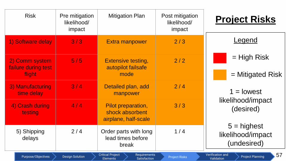
Risk Pre mitigation
likelihood/
impact
Mitigation Plan Post mitigation
likelihood/
impact
1) Software delay 3 / 3 Extra manpower 2 / 3
2) Comm system
failure during test
flight
5 / 5 Extensive testing,
autopilot failsafe
mode
2 / 2
3) Manufacturing
time delay
3 / 4 Detailed plan, add
manpower
2 / 4
4) Crash during
testing
4 / 4 Pilot preparation,
shock absorbent
airplane, half-scale
3 / 3
5) Shipping
delays
2 / 4 Order parts with long
lead times before
break
1 / 4
Legend
= High Risk
= Mitigated Risk
1 = lowest
likelihood/impact
(desired)
5 = highest
likelihood/impact
(undesired)
Project Risks

Critical Project Elements
Purpose/Objectives Design Solution Project RisksRequirements Satisfaction
Project PlanningVerification and
ValidationProject Risks 58
Risk Pre mitigation
likelihood/
impact
Mitigation Post mitigation
likelihood/
impact
6) Wing failure
during sandbag
test
2 / 3 Buy 2 sets of wings,
Produce extra
2 / 2
7) Battery
overheating
3 / 5 Test components and
circuit
1 / 5
8) Injury during
testing
2 / 5 Safety plan 1 / 5
9) Over-budget 4 / 4 Budget plan, half-
scale testing
2 / 4
10) Insufficient
battery duration
during flight
3 / 4 Battery testing,
autopilot safeguard
2 / 3
11) Bad weather 3 / 2 Plan ahead, have
multiple options
3 / 1
Legend
= High Risk
= Mitigated Risk
1 = lowest
likelihood/impact
(desired)
5 = highest
likelihood/impact
(undesired)
Project Risks

Critical Project Elements
Purpose/Objectives Design Solution Project RisksRequirements Satisfaction
Project PlanningVerification and
ValidationProject Risks
Pre Mitigation Risk Matrix
59

Critical Project Elements
Purpose/Objectives Design Solution Project RisksRequirements Satisfaction
Project PlanningVerification and
ValidationProject Risks
Post Mitigation Risk Matrix
60
4) 9)
3) 10)
2)
7)
8)

Critical Project Elements
Purpose/Objectives Design Solution Project RisksRequirements Satisfaction
Project PlanningVerification and
Validation
Verification and Validation
Verification and Validation
61

Critical Project Elements
Purpose/Objectives Design Solution Project RisksRequirements Satisfaction
Project PlanningVerification and
Validation
Verification and Validation
62
Motivation Expected Result According to Models Off-Ramp
Validate stability modelUse accelerometers to confirm predicted
behavior Iteration of model
DR 1.1- Half Scale Stability TestAnticipated Date: On or before the week of January 15th
DR 1.1 The control system shall provide required control surface deflections for aircraft longitudinal and lateral
stability throughout all phases of flight.
Test set-up:
Half scale UAV
Accelerometer

Critical Project Elements
Purpose/Objectives Design Solution Project RisksRequirements Satisfaction
Project PlanningVerification and
Validation
Verification and Validation
63
Equipment Availability Capabilities Requirements Satisfied?
Half scale modelAcquired
through funds
Provide reliable
test data for
validation
Validate stability
model
Stability model
verified
Accelerometer COTSRange: 0-14.2g
Resolution: 16 bit
Continuously track
the UAV’s roll pitch
and yaw
COTS
accelerometer
capable with
resolution
Key Measurements Issues: Accelerometer resolution
DR 1.1- Half Scale Stability TestExpected Location: South Campus

Critical Project Elements
Purpose/Objectives Design Solution Project RisksRequirements Satisfaction
Project PlanningVerification and
Validation
Verification and Validation
64
Motivation Expected Result According to Models Off-Ramp
Validate Speed Model Dolly speed is 13.2 m/s
Add or remove bungees,
vary pull back distance on
ramp.
DR 2.1 - Launch Speed TestAnticipated Date: After TRR
Test set-up:
Camera captures
dolly as it moves
up the ramp
DR 2.1 The launch system shall accelerate the UAV to 13.2 m/s by the end of ramp.

Critical Project Elements
Purpose/Objectives Design Solution Project RisksRequirements Satisfaction
Project PlanningVerification and
Validation
Verification and Validation
65
Equipment Availability Capabilities Requirements Satisfied?
Camera ITLL60 fps camera
Launch time: 0.766 s
> 20 frames for
track time
45 frames in
launch time
Tripod/Stand ITLLAny height is
achievable0.25 m height
Any Height
Logger Pro
SoftwareITLL
Frame by frame
tracking of dolly to
find position and
speed
Calculate the
speed of the
dolly
Access to
software
Key Measurements Issues: Error in height of camera leading to issues in software
DR 2.1 - Launch Speed TestExpected Location: Open Field
Critical Project Elements
Purpose/Objectives Design Solution Project RisksRequirements Satisfaction
Project PlanningVerification and
Validation
Verification and Validation
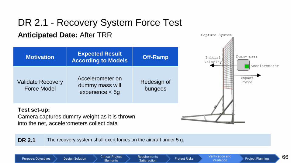
DR 2.1 - Recovery System Force Test
Anticipated Date: After TRR
66
Motivation Expected Result
According to ModelsOff-Ramp
Validate Recovery
Force Model
Accelerometer on
dummy mass will
experience < 5g
Redesign of
bungees
Capture System
Dummy massInitial
Velocity
Impact
Force
Accelerometer
DR 2.1 The recovery system shall exert forces on the aircraft under 5 g.
Test set-up:
Camera captures dummy weight as it is thrown
into the net, accelerometers collect data

Critical Project Elements
Purpose/Objectives Design Solution Project RisksRequirements Satisfaction
Project PlanningVerification and
Validation
Verification and Validation
67
Equipment Availability Capabilities Requirements Satisfied?
Accelerometer COTSRange: 0-14.2 g
Resolution: 16 bit5 g
Available
High Speed
CameraITLL 120 fps
Record dummy
mass to find net
extension
Available
Dummy Mass ITLL N/A 8.45 kgAvailable
DR 2.1 - Recovery System Force Test
Expected Location: Open Field
Key Measurements Issues: Consistent throw speeds, error in measurements from
accelerometer.

Critical Project Elements
Purpose/Objectives Design Solution Project RisksRequirements Satisfaction
Project PlanningVerification and
Validation
Verification and Validation
DR 3.1 - Datalink Range Test
Anticipated Date: February 1, 2018
68
Motivation Expected Result
According to ModelsOff-Ramp
Verify 12 km
communication
range
Successful image transfer
Uplink rate of 8 kbps
Datalink rate of 88 kbps.
Implementation
of ground
station tracking
system
RFD900+
Laptop
FTDI
Cable
RFD900+12 km
900 MHz
Yagi antenna 900 MHz ¼
wave monopole
Battery
Powered
USB Hub
Laptop
FTDI
Cable
Battery
Powered
USB Hub
8 kbps
88 kbps
DR 3.1 Telemetry radio shall have a range of 12 km at 90+ kbps.
Test set-up:
Ground station setup will be 12 km away from transmitter

Critical Project Elements
Purpose/Objectives Design Solution Project RisksRequirements Satisfaction
Project PlanningVerification and
Validation
Verification and Validation
69
Equipment Availability Capabilities Requirements Satisfied?
2 FTDI
Cables
Acquired
through
funds
Communicate
between radio and
laptop
5V capacity
Can be
purchased with
budget
2 Battery
Powered
USB Hubs
Acquired
through
funds
Provide extra power
to radio
At least 88 kbps
transfer rate
Can be
purchased with
budget
DR 3.1 - Datalink Range TestExpected Location: Flatiron summit to Boulder/Lafayette City limit at Baseline Rd
Key Measurements Issues: Ground station pointing angle of antenna.

Critical Project Elements
Purpose/Objectives Design Solution Project RisksRequirements Satisfaction
Project PlanningVerification and
Validation
Verification and Validation
DR 6.2 - Battery Endurance TestVerify the battery can reach the mission time requirement
Anticipated Date: Before TRR
70
Motivation Expected Result
According to Models
Off-Ramp
Validate Power
Budget
Battery holds charge for:
3 min at 65.6A
81 min at 15.6A
Reduce
required range
of mission.
+ -
R
V
Battery
Load
Voltmeter
Timer
DR 6.2 Battery shall have 1.4 hr endurance.
Test set-up:
Ground test of battery connected to load and voltmeter

Critical Project Elements
Purpose/Objectives Design Solution Project RisksRequirements Satisfaction
Project PlanningVerification and
Validation
Verification and Validation
71
Equipment Availability Capabilities Requirements Satisfied?
Motor,
Autopilot,
Flight
Computer
Acquired
through
funds
Simulate mission
load on battery
Components
chosen for
project
Components to
be ordered
Compact
DAQITLL
Verify the battery
voltage over time
and measure the
cutoff voltage
84 min
measurement
time
Can measure
values over time
DR 6.2 - Battery Endurance TestExpected Location: ITLL
Key Measurements Issues: Error in DAQ measurements.

Critical Project Elements
Purpose/Objectives Design Solution Project RisksRequirements Satisfaction
Project PlanningVerification and
Validation
Verification and Validation
Verification & Validation Summary
72
Models Validated Requirements verified
Stability model Aircraft stability during flight
Launch system speed modelCapability of launch system to deliver
necessary energy to UAV
Recovery system force modelCapability of landing system to capture
UAV with forces in under 5g
Battery depletion modelBattery shall have 1.4 hour endurance
between climb and cruise
Link Budget Capability of ground system to
communicate with UAV at range

Critical Project Elements
Purpose/Objectives Design Solution Project RisksRequirements Satisfaction
Project PlanningVerification and
Validation Project Planning
Project Planning
73

Critical Project Elements
Purpose/Objectives Design Solution Project RisksRequirements Satisfaction
Project PlanningVerification and
Validation Project Planning
Organizational Chart
74

Critical Project Elements
Purpose/Objectives Design Solution Project RisksRequirements Satisfaction
Project PlanningVerification and
Validation Project Planning
Work Breakdown Structure
75
Completed
To Be
Completed

Critical Project Elements
Purpose/Objectives Design Solution Project RisksRequirements Satisfaction
Project PlanningVerification and
Validation Project Planning
Test Plan
76

Critical Project Elements
Purpose/Objectives Design Solution Project RisksRequirements Satisfaction
Project PlanningVerification and
Validation Project Planning
Work Plan (Gantt Chart)
77
Planned
Margin
Critical Path
Winter Break/
Parts Procurement /
Software Development
Manufacturing /
Software Development

Critical Project Elements
Purpose/Objectives Design Solution Project RisksRequirements Satisfaction
Project PlanningVerification and
Validation Project Planning
Work Plan (Gantt Chart Continued)
78
Planned
Margin
Planned
Margin
Critical PathComponent Testing /
Integration and Assembly
Integration Testing

Critical Project Elements
Purpose/Objectives Design Solution Project RisksRequirements Satisfaction
Project PlanningVerification and
Validation Project Planning
Budget Estimations
79
Airframe w/ motor: $1230
Communications: $530
Electronics: $800
Launch system: $295
Recovery system: $510
Software $320
Total: $3,685 < $5,000
Leaves the SHAMU team
with a 26% margin

Critical Project Elements
Purpose/Objectives Design Solution Project RisksRequirements Satisfaction
Project PlanningVerification and
Validation Project Planning
Acknowledgements
80
Thank you to Dr. Gerren, Dr. Koster, Dr. Lawrence, Trudy
Schwartz, Bobby Hodgkinson, Matt Rhode, PAB, Tim
Kiley, Lee Huynh, James Nestor, and David Gruber.

Critical Project Elements
Purpose/Objectives Design Solution Project RisksRequirements Satisfaction
Project PlanningVerification and
Validation Project Planning
References
81
● Cooper-Harper scale: https://skybrary.aero/bookshelf/books/1962.pdf (retrieved 12/3/17)
● Pixhawk 2.1 Assembly Guide: http://www.hex.aero/wp-content/uploads/2016/09/PIXHAWK2-Assembly-Guide.pdf
(retrieved 12/3/17)
● Pixhawk 2.1 Feature Overview: http://www.proficnc.com/index.php?controller=attachment&id_attachment=5
(retrieved 12/3/17)
● PX4 Pro: http://px4.io/ (retrieved 12/3/17)
● QGroundControl: http://qgroundcontrol.com/ (retrieved 12/3/17)
● Model Aircraft Propellers:
https://www.google.com/url?sa=t&rct=j&q=&esrc=s&source=web&cd=6&cad=rja&uact=8&ved=0ahUKEwjO8MLoh-
_XAhVD6oMKHduWDCsQFghrMAU&url=http%3A%2F%2Fdc-
rc.org%2Fpdf%2FModel%2520Propellers%2520Article.pdf&usg=AOvVaw1CxfDyyhN4K5DlHAanXPPt (retrieved
12/3/17)
● OrangeRx Open LRS Transmitter: https://hobbyking.com/en_us/orangerx-open-lrs-433mhz-transmitter-1w-jr-turnigy-
compatible.html (retrieved 12/3/17)
● OrangeRx Open LRS Receiver: https://hobbyking.com/en_us/orangerx-open-lrs-433mhz-9ch-receiver.html (retrieved
12/13/17)
● UIAA climbing rope: http://www.theuiaa.org/safety-standards/
● Solidworks: http://www.solidworks.com/
● PVC porperties: https://www.engineeringtoolbox.com/physical-properties-thermoplastics-d_808.html
● PVC pressure ratings: https://www.engineeringtoolbox.com/pvc-cpvc-pipes-pressures-d_796.html

Critical Project Elements
Purpose/Objectives Design Solution Project RisksRequirements Satisfaction
Project PlanningVerification and
Validation Project Planning
Questions?
82
Thank you.

Critical Project Elements
Purpose/Objectives Design Solution Project RisksRequirements Satisfaction
Project PlanningVerification and
Validation Project Planning
Backup Slides Directory
83
Airframe & Powerplant:
Propeller
Winglet Magnets
Modularity
Half Scale Model
X-Plane Model
Climb Rate
Cooper-Harper
Servo Selection
C.G. Range Longitudinal Stability
C.G. Range Lateral Stability
Uncontrolled Eigenvalues
Launch System:
Launch Flow Chart
Forces and Displacements (Dolly)
Restraining Rope
Anchors (Bungee and Rope)
PVC Cement
Dolly pictures
Modularity and dimensions
Beam Bending
Capture System:
Modularity and Dimensions
Pulley/Cleat System CAD
Connection Details
Tipping and Sliding
Electronics:
Electronics Layout
Climb Power
Cruise Power
Component Current Draw
Electronics Diagram
From Electronics Diagram
Motor Requirement
Nav/Comm:
Software Overview
mavimage Overview
mavimage UML Class Diagram
(overview)
mavimage UML Class Diagram
mavtables Overview
mavtables UML Class Diagram
(overview)
mavtables UML Class Diagram
mavlogger overview
mavlogger UML Class Diagram
Image Resolution
Image Transfer Rate
Datalink Budget
Slide 132: CPE: Nav/Comm Requirements
Testing:
Testing Backup

Critical Project Elements
Purpose/Objectives Design Solution Project RisksRequirements Satisfaction
Project PlanningVerification and
Validation
Airframe & Powerplant Backup
84

Critical Project Elements
Purpose/Objectives Design Solution Project RisksRequirements Satisfaction
Project PlanningVerification and
ValidationDesign Solutions
Propeller backup slide
85
Propeller configuration
● 16 x 10 inch 2-blade propeller
● Carbon fiber
● Folding design
● Up to 6.4 kg thrust
● Pitch speed: 31 m/s (cruise speed: 20 m/s)

Critical Project Elements
Purpose/Objectives Design Solution Project RisksRequirements Satisfaction
Project PlanningVerification and
ValidationDesign Solutions
Magnet backup slide
86
● Neodymium N52 magnets with 25.1 N pull force
● Two magnet sets per wing to prevent rotation: 2*25.1 = 50.2 N
pull force per winglet
● Simulation at 30.5 m/s (never exceed speed) and beta angle of 10
degrees produced side force of 17.4 N lbs per winglet
● Winglets will not depart during worst case scenario flight loads
(50.2 N > 17.4 N) safety factor = 2.9
● Winglet will depart under non-nominal landing load (> 50.2 N)

Critical Project Elements
Purpose/Objectives Design Solution Project RisksRequirements Satisfaction
Project PlanningVerification and
ValidationRequirements Satisfaction
Aerial Vehicle Design Key Requirements
87
50% Scale Model:
● Useful for static stability and handling
characteristics
○ Statically stable (CMα < 0) except at stall
○ Poor stall behavior
● 3° wing twist requirement developed for design
as a result
Launching the half-scale model.

Critical Project Elements
Purpose/Objectives Design Solution Project RisksRequirements Satisfaction
Project PlanningVerification and
ValidationRequirements Satisfaction
Aerial Vehicle Design Key Requirements
88
X-Plane 10 Model:
● Useful for modeling stability and handling
characteristics from a pilot’s perspective
○ Max roll rate: 70°/s
○ Max pitch rate: 45°/s
○ Statically stable (CMα < 0) in all flight
conditions with 3° wing twist
○ Dynamically stable
● Will be used for hardware in the loop simulations
with autopilot.
X-Plane Rendering of SHAMU UAV

Critical Project Elements
Purpose/Objectives Design Solution Project RisksRequirements Satisfaction
Project PlanningVerification and
ValidationRequirements Satisfaction
Aerial Vehicle Design Key Requirements
89
Design Decisions for modularity
● Winglet magnets detach
● Remove 2 nuts to detach wings
● 4 bolts removed to detach
payload bay
Packs into a 152 cm x 97 cm x 31 cm
volume.
DR 7.1 Aircraft and associated systems shall break down to fit in a 168 x 122 x 46 cm container for
transportation.

Critical Project Elements
Purpose/Objectives Design Solution Project RisksRequirements Satisfaction
Project PlanningVerification and
ValidationRequirements Satisfaction
Aerial Vehicle Design Key Requirements
90
Servo selection:
● AVL used to calculate worst-case control
surface hinge moment
○ Vne= 1.5*Vcruise
○ Max elevon deflection
● Hinge moment = 14 kg*cm
● HK15298B servo
○ Stall torque: 18.0 kg*cm @ 6.0V
○ Stall torque: 20.0 kg*cm @ 7.4V
○ Dimension: 18.0 x 121.0 x 80.0
mm
○ Mass: 0.09 kghttps://hobbyking.com/en_us/hobbykingtm-coreless-digital-
hv-mg-bb-servo-20kg-0-16sec-66g.html

Critical Project Elements
Purpose/Objectives Design Solution Project RisksRequirements Satisfaction
Project PlanningVerification and
ValidationRequirements Satisfaction
Aerial Vehicle Design Key Requirements
91
Cooper-Harper Scale 3: “Satisfactory without improvement. Fair; some mildly unpleasant deficiencies -
minimum pilot compensation required for desired performance.”
Quantitatively:
● Maximum pitch and roll rates: 30 - 360°/s at minimum controllable airspeed.
● CMα < 0 through flight regime (angles of attack from zero to stall) → statically stable.
● Real component of phugoid/short period/dutch roll/rolling modes must be less than zero →
dynamically stable.

Critical Project Elements
Purpose/Objectives Design Solution Project RisksRequirements Satisfaction
Project PlanningVerification and
ValidationRequirements Satisfaction
CPE: Aerial Vehicle Design Key Requirements
92
● Flying wing configuration
● Elevon control (pitch and roll)
● Outer 50% span, 25% chord elevons.
● Elevon maximum deflections: +/- 30°
● Trim conditions for steady-level flight:
○ Elevon: -10 deg deflection (AVL)
● Mass: 8.45 kg
● Aerodynamic center: 71.75 cm
○ Including wing and fuselage effects
● Center of gravity w/2 kg payload: 64.93 cm
● Static Margin: 22.4% (6.82 cm)
Aircraft side view

Critical Project Elements
Purpose/Objectives Design Solution Project RisksRequirements Satisfaction
Project PlanningVerification and
ValidationRequirements Satisfaction
CPE: Aerial Vehicle Design Key Requirements
93
AVL Model Eigenvalues:
● 𝝺i < 0 ∀ i
○ Stable in the sense
of Lyapunov
○ System is BIBS &
BIBO stable

Critical Project Elements
Purpose/Objectives Design Solution Project RisksRequirements Satisfaction
Project PlanningVerification and
ValidationCritical Project
Elements
Aircraft Stability- AVL/Matlab
● Longitudinal eigenvalue
locus plot
○ Range of C.G. :
approx. 62.9 +/- 15 cm
94
Short period mode - very stable
Phugoid mode - slightly stable for C.G.
range of 50.7 cm - 76.3 cm
∴ Feasible

Critical Project Elements
Purpose/Objectives Design Solution Project RisksRequirements Satisfaction
Project PlanningVerification and
ValidationCritical Project
Elements
Aircraft Stability- AVL/Matlab
● Lateral eigenvalue locus
plot
○ Range of C.G. :
approx. 62.9 +/- 15 cm
95
Roll mode - very stable
Dutch roll; Spiral modes - slightly
stable for C.G. range of 50.7 cm - 76.3
cm
∴ Feasible

Critical Project Elements
Purpose/Objectives Design Solution Project RisksRequirements Satisfaction
Project PlanningVerification and
Validation
Launch System Backup
96

Critical Project Elements
Purpose/Objectives Design Solution Project RisksRequirements Satisfaction
Project PlanningVerification and
Validation
Launch Flow Chart
97

Critical Project Elements
Purpose/Objectives Design Solution Project RisksRequirements Satisfaction
Project PlanningVerification and
ValidationRequirements Satisfaction
Maximum Allowable Loading
98
● Factor of Safety = 2
● Maximum allowable
force = 1700N
● 4 bungees used
produce 2.6 in2 of
contact on front dolly
bar
● Actual force on dolly
bar from bungees =
343.33 N
● PVC tensile strength =
40.7 MPa
● PVC type Schedule 40

Critical Project Elements
Purpose/Objectives Design Solution Project RisksRequirements Satisfaction
Project PlanningVerification and
ValidationRequirements Satisfaction
PVC Displacement
99
Max displacement = 1.5 mm

Critical Project Elements
Purpose/Objectives Design Solution Project RisksRequirements Satisfaction
Project PlanningVerification and
ValidationRequirements Satisfaction
Force on Dolly From Restraining Rope
100
Dolly mass: 5.91 kg
Vf = 13.2 m/s
Max allowable force on dolly: 1700N
Stopping impulse force, Favg = m*aavg*(ΔV/Δt)
● At max force Δt = 0.046s
Stopping distance, x = Vo*t + 0.5*(-a)*t2
● At max force x = 0.310m
Force safety increase stopping distance to 0.5m
● Time to stop, t = 0.076s
● Force on dolly, F = 1026.5 N

Critical Project Elements
Purpose/Objectives Design Solution Project RisksRequirements Satisfaction
Project PlanningVerification and
ValidationRequirements Satisfaction
Restraining Rope
101
Material used: low stretch polyester rope
● Rated for 6% to 10% dynamic elongation
● 1556 N load capable
● FoS = 1.5
Recall stopping distance = 0.5 m
● Length of rope required for this stopping distance = 8.3 m to 5 m
Critical Project Elements
Purpose/Objectives Design Solution Project RisksRequirements Satisfaction
Project PlanningVerification and
ValidationRequirements Satisfaction
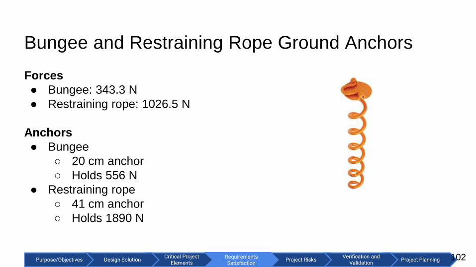
Bungee and Restraining Rope Ground Anchors
102
Forces
● Bungee: 343.3 N
● Restraining rope: 1026.5 N
Anchors
● Bungee
○ 20 cm anchor
○ Holds 556 N
● Restraining rope
○ 41 cm anchor
○ Holds 1890 N

Critical Project Elements
Purpose/Objectives Design Solution Project RisksRequirements Satisfaction
Project PlanningVerification and
ValidationRequirements Satisfaction
PVC Cement and Its Strength
103
Known: Same PVC cement is used for Schedule 40 and Schedule 80.
Assumption based off capped pipes. Since the area is the same for a 1 in
diameter pipe for Sch 40 and Sch 80, the operating pressure of sch 80 pipe is
used. Know that PVC cement should hold operating pressures of pipes.
Area of cap: 5.42 cm2
Operating pressure Sch 80: 2.61 MPa
Bursting pressure Sch 80: 13.93 MPa
Operating force of Sch 80, Area * pressure = 1412.5 N
Force that will burst Sch 80, F = 7548.4 N
Max force dolly experiences = 1026.5 N < 1412.5 N < 7548.4 N

Critical Project Elements
Purpose/Objectives Design Solution Project RisksRequirements Satisfaction
Project PlanningVerification and
ValidationRequirements Satisfaction
Pictures of Dolly
104

Critical Project Elements
Purpose/Objectives Design Solution Project RisksRequirements Satisfaction
Project PlanningVerification and
ValidationRequirements Satisfaction
Pictures of Dolly
105

Critical Project Elements
Purpose/Objectives Design Solution Project RisksRequirements Satisfaction
Project PlanningVerification and
ValidationRequirements Satisfaction
Dolly
Dimensions
106

Critical Project Elements
Purpose/Objectives Design Solution Project RisksRequirements Satisfaction
Project PlanningVerification and
ValidationRequirements Satisfaction
DR 7.1 Satisfied
107
Primary Concern:
Ramp rails are 5.8 meters (580 cm)
Solution:
Rail segments (<168cm) connected by a
threaded, aluminum rod inside the pipe
Result:
4 rail segments at 1.47 meters each
3 threaded internal pipe connectors
CPE: Launch Design Key Requirements
DR 7.1 Launch and associated systems shall break down to fit in a 168 x 122 x 46 cm container for transportation.
SolidWorks Rendering: PVC Launch
Ramp RailRail Segments 147 cm < 168 cm

Critical Project Elements
Purpose/Objectives Design Solution Project RisksRequirements Satisfaction
Project PlanningVerification and
ValidationRequirements Satisfaction
Finding the Spring Constant required for TO
108
Assumptions:
5 Hi-start Bungees
Max weight: 5 kg
Max elongation: 3 times original length
K found by hanging mass off ceiling (Mg = Kx)
Applied to Conservation of Energy for
different bungee lengths,
Intersecting point will give K value for needed
TO speed
Results:
Total Mass: 13.9657 kg
Force: 343.3333 N (5 Bungees)
Spring Constant: 86.0011 N/m
Initial Bungee length: 1.9961 m
Bungee-stretch: 3.9922 m

Critical Project Elements
Purpose/Objectives Design Solution Project RisksRequirements Satisfaction
Project PlanningVerification and
ValidationRequirements Satisfaction
Effective Bungee Force
109
Assumptions:
Bungee Force will decrease as dolly moves
Bungees tied to ground in front of ramp
Accounted for change in bungee force and the
change in direction.
Results:
Look at plots
Force the Dolly feels fades to zero
Gives effect of consistent pull by bungee

Critical Project Elements
Purpose/Objectives Design Solution Project RisksRequirements Satisfaction
Project PlanningVerification and
ValidationRequirements Satisfaction
Speed model
110
Assumptions:
Total Mass: 13.9657 kg
Force: 343.3333 N (5 Bungees)
Spring Constant: 86.0011 N/m
Initial Bungee length: 1.9961 m
Bungee-stretch: 3.9922 m
Effective Bungee Force Data
Applied Newton’s first law and integrated to
get equations of motion
Results:
Aircraft gets to speed 0.0405 after end of ramp,
this is adjusted for, shown in plot
New ramp length: 5.2480 m
Time: 0.6851 s
Velocity at exit: 13.208 m/s

Critical Project Elements
Purpose/Objectives Design Solution Project RisksRequirements Satisfaction
Project PlanningVerification and
ValidationRequirements Satisfaction
Beam Bending
111
Assume:
● Two fixed supports
● Each point on ramp has load F shown by the blue line
● Load F is the effective Bungee Force plus the weight of UAV
● Material Properties of PVC schedule 40
● 5.25 m long 2” PVC pipe

Critical Project Elements
Purpose/Objectives Design Solution Project RisksRequirements Satisfaction
Project PlanningVerification and
ValidationRequirements Satisfaction
Beam Bending (Continued)
112
Results:
Max Deflection of Beam: 3.857901 mm
At a Distance of: 2.4564 meters
Model stops when UAV is at speed~4 meters, the
rest of the rail is there for stopping distance
Max Bending Stress =153.0242 KPa
𝞼 bend,max = 99.63 MPa
Safety Factor = 651.1

Critical Project Elements
Purpose/Objectives Design Solution Project RisksRequirements Satisfaction
Project PlanningVerification and
ValidationRequirements Satisfaction
Reaction Forces
113
Assumptions:
● Two fixed supports
● Sum of the moments
● Effective Bungee Force data
Results:
First Support: Max compressive force of: 90.3230 N
Second Support: Max compressive force of: 52.1098 N
Compressive Stress: 155.3157 KPa
Max Compressive Force (PVC 40): 66.2 MPa
Safety Factor: 426.2

Critical Project Elements
Purpose/Objectives Design Solution Project RisksRequirements Satisfaction
Project PlanningVerification and
Validation
Recovery System Backup
114

Critical Project Elements
Purpose/Objectives Design Solution Project RisksRequirements Satisfaction
Project PlanningVerification and
ValidationRequirements Satisfaction
CPE: Recovery System Requirements
115
FR 7 Aircraft and associated systems shall be modular to support future modifications, repairs, and to fit in a
truck bed for transportation.
DR 7.1 Each capture system component fits within 168 x 122 x 46 cm container.
● Recovery System Structure made from 9cm outer diameter PVC pipe
● Max section length 168 cm
● Total sections required 34
● Smaller sections can be stored end-to-end
● 39+ sections will fit 22 lengthwise rows
● Stored 13 across, 2 up
fits 165x117x18 cm space < 168 x 122 x 46 cm space
∴ FR 7, DR 7.1 Satisfied

Critical Project Elements
Purpose/Objectives Design Solution Project RisksRequirements Satisfaction
Project PlanningVerification and
ValidationRequirements Satisfaction
Pulley/Cleat System CAD
116
Bungee Attachment, Cleat, And Double
Pulley View
Swivel Pulley and Net attachment
View

Critical Project Elements
Purpose/Objectives Design Solution Project RisksRequirements Satisfaction
Project PlanningVerification and
ValidationRequirements Satisfaction
Connection Details
117
● Bungee/Pulleys are connected and rope is guided through ¼” eyebolts, 2200lb working load
● Connections between eyebolts/pulleys and between lines are made with ¼” quick links
● Rope and Bungee both have 3/16” diameter
● Rope has 400 N working load
● Cam Cleat has 850 N working load, accepts up to ¼” rope
● All pulleys and quick links have at least 1870 N working load
Cam CleatQuick Link Eyebolt

Critical Project Elements
Purpose/Objectives Design Solution Project RisksRequirements Satisfaction
Project PlanningVerification and
ValidationRequirements Satisfaction
Tipping and Sliding Calculation
118
● CG location of net structure is 2.6 meters in front of and 0.61 meters above pivot
● If CG is tipped above pivot, CG will be raised to 2.3 meters
● Structure mass 69 kg
● 1135.5 J required to fully tip structure, > 572 J Capture force
● Tipping risk further mitigated with sandbags on foreward supports
● 69 kg structure has 676 N normal force
● Expected coefficient of friction at least 1 (Helipad nonskid)
● F_k = 676 N > Maximum capture force of 395 N, Will not slide

Critical Project Elements
Purpose/Objectives Design Solution Project RisksRequirements Satisfaction
Project PlanningVerification and
Validation
Electronics Backup
119

Critical Project Elements
Purpose/Objectives Design Solution Project RisksRequirements Satisfaction
Project PlanningVerification and
ValidationRequirements Satisfaction
Aerial Vehicle Design Requirement
120
5 m/s climb rate requires a motor with:
● 812 W Power
● 30.3 N Thrust
Selected Electric Motor
Model: PROPDRIVE v2 5060 380KV
Specifications
KV: 380 KV
Continuous Power: 1500 W
PROPDRIVE (selected motor)
Calculated Thrust: 46.3 N > 30.3 N
Power: 1500 W
> 812 W
Fulfills 5 m/s climb rate
∴ DR 2.3 Satisfied
Thrust for Model Aircraft
Ct: coefficient of thrust (0.09, Garner reference)
⍴: air density (0.00238 slug/ft3, sea level)
n: revolutions per second (141 rev/s, spec. sheet)
D: diameter of the propeller (1.25 ft spec. sheet)
DR 2.3 The aircraft shall have a climb rate of 5 m/s

Critical Project Elements
Purpose/Objectives Design Solution Project RisksRequirements Satisfaction
Project PlanningVerification and
ValidationDesign Solutions
Electronics Layout
121

Critical Project Elements
Purpose/Objectives Design Solution Project RisksRequirements Satisfaction
Project PlanningVerification and
Validation
Verification and Validation
Climb PowerGiven: Velocity = 20 m/s, Climb Rate = 5 m/s
Weight = 111.12 N, L/D = 12, t = 0.05
hr
Need: Power [W] = Thrust [N] * Velocity [m/s]
Thrust
Climb Angle Equation:
sin(ɣ) = (Thrust - Drag)/ (Weight)
Aim for climb rate of 5 m/s and maintain speed at
20 m/s
From a): ɣ = sin-1(5 / 20) = 14.5°
Solve Climb Angle Equation for Thrust
Thrust = Weight*sin(ɣ) + D
= 30.43N
Power = 30.43 N * 20 m/s = 608.62 W
Assuming 0.75 efficiency
Power = 792 W
Energy Required = 792 * 0.05 = 39.6 Whr122

Critical Project Elements
Purpose/Objectives Design Solution Project RisksRequirements Satisfaction
Project PlanningVerification and
Validation
Verification and Validation
Cruise Power Power in Flight:
Power [W] = Thrust [N] * Velocity [m/s]
Given L/D = 12
Assuming Steady Level Flight
Lift = Weight = 89 N
⇒Thrust = 7.4 N
Using Computed Thrust and Velocity
Power = 7.4 * 20 m/s = 1748 W
Assuming propulsion efficiency of 0.75
Power = 198 W
100 km range with 20 m/s speed ⇒time = 1.4 hrs
Energy Required = Power [W] * time
[hr]
= 198 * 1.4 = 277 Wh
Velocity = 20 m/s
123

Critical Project Elements
Purpose/Objectives Design Solution Project RisksRequirements Satisfaction
Project PlanningVerification and
Validation
Verification and Validation
FR 6- Component Current Draw TestsVerify advertised current draw in each component (Radio, GPS, Pixhawk, Servo etc.)
124
Motivation Expected Result Off-Ramp
Confirm Components’
Current Draw
Actual component
current draw is within
10% error of advertised
current draw
Reduce
required range
of mission.
Equipment Location Requirements Satisfied?
Power Supply ITLLAble to Supply 5V to
componentAccess to Power Supplies
Ammeter ITLLAble to measure up to
65A of currentAccess to Ammeter

Critical Project Elements
Purpose/Objectives Design Solution Project RisksRequirements Satisfaction
Project PlanningVerification and
Validation
Verification and Validation
Electronics Diagram
125

Critical Project Elements
Purpose/Objectives Design Solution Project RisksRequirements Satisfaction
Project PlanningVerification and
Validation
Verification and Validation
From Electronic Layout
126
Needed Wire Gauge:
● Copper Size 4 between battery, sensor board, ESC, and motor.
● Copper Size 18 for everything else
Heat Generation:
● 6S Batteries typically have internal resistance of 6 milliohms. (Will
verify during battery endurance test). At 15A → 1.35 W of heat
generation.
● ESC internal resistance .0022 Ohms. At 15A → .495 W of heat
generation.
● Motor is assumed to have 75% efficiency → 25% of energy supplied
is heat. Supplied power is 22.2V at 15A is 333W → 83.25 W of heat
generation.
● Total BOTE heat generation: 85W
Q = IV = I2RQ: heat generation
I: Current
V: Voltage
R: Resistance

Critical Project Elements
Purpose/Objectives Design Solution Project RisksRequirements Satisfaction
Project PlanningVerification and
Validation
Nav/Comm Backup
127

Critical Project Elements
Purpose/Objectives Design Solution Project RisksRequirements Satisfaction
Project PlanningVerification and
ValidationRequirements Satisfaction
DR 3.2 Aircraft shall capture and transmit images to ground station at 1/60 Hz.
CPE: Nav/Comm Requirements
128
● Image capture and transmission accomplished with
mavimage.
○ Written in Python (to lower development time).
○ UML class diagram complete.
○ 22 classes in design.
● Ground station receiving of images and saving to disk
also accomplished with mavimage.
● Images sent over telemetry link. mavtables used to
mix image and telemetry packets.
○ Written in C++17 (to increase runtime speed).
○ UML class diagram complete.
○ 32 classes in design.
● Requires 70.0 kbps (95.0 kbps of download available) From UML class diagrams.
UML diagrams in backup slides and can be
provided at full resolution upon request.
Critical Project Elements
Purpose/Objectives Design Solution Project RisksRequirements Satisfaction
Project PlanningVerification and
ValidationProject Risks
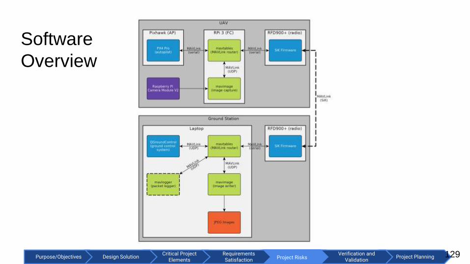
Software
Overview
129
Critical Project Elements
Purpose/Objectives Design Solution Project RisksRequirements Satisfaction
Project PlanningVerification and
ValidationProject Risks
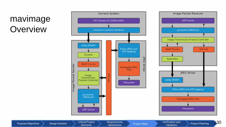
mavimage
Overview
130

Critical Project Elements
Purpose/Objectives Design Solution Project RisksRequirements Satisfaction
Project PlanningVerification and
Validation
131
mavimage UML Class Diagram

Critical Project Elements
Purpose/Objectives Design Solution Project RisksRequirements Satisfaction
Project PlanningVerification and
ValidationRequirements Satisfaction
DR 3.2 Aircraft shall capture and transmit images to ground station at 1/60 Hz.
CPE: Nav/Comm Requirements
132
● Image capture and transmission accomplished with
mavimage.
○ Written in Python (to lower development time).
○ UML class diagram complete.
○ 22 classes in design.
● Ground station receiving of images and saving to disk
also accomplished with mavimage.
● Images sent over telemetry link. mavtables used to
mix image and telemetry packets.
○ Written in C++17 (to increase runtime speed).
○ UML class diagram complete.
○ 32 classes in design.
● Requires 70.0 kbps (95.0 kbps of download available) From UML class diagrams.
UML diagrams in backup slides and can be
provided at full resolution upon request.

Critical Project Elements
Purpose/Objectives Design Solution Project RisksRequirements Satisfaction
Project PlanningVerification and
Validation
133
mavimage UML Class Diagram
(overview)

Critical Project Elements
Purpose/Objectives Design Solution Project RisksRequirements Satisfaction
Project PlanningVerification and
ValidationProject Risks
Mavtables
Overview
134

Critical Project Elements
Purpose/Objectives Design Solution Project RisksRequirements Satisfaction
Project PlanningVerification and
Validation
135
mavtables UML Class Diagram
(overview)

Critical Project Elements
Purpose/Objectives Design Solution Project RisksRequirements Satisfaction
Project PlanningVerification and
Validation
136
mavtables UML Class Diagram

Critical Project Elements
Purpose/Objectives Design Solution Project RisksRequirements Satisfaction
Project PlanningVerification and
ValidationProject Risks 137
mavlogger
Overview

Critical Project Elements
Purpose/Objectives Design Solution Project RisksRequirements Satisfaction
Project PlanningVerification and
Validation
138
mavlogger UML Class Diagram

Critical Project Elements
Purpose/Objectives Design Solution Project RisksRequirements Satisfaction
Project PlanningVerification and
ValidationProject Risks
Image Resolution
139
● 1920x1080 (2MP) - downsampled
● 62O FOV (field of view)
● 0.6m x 0.6m pixel size
● Adult sperm whale: ~16m x 3m
● 1920x1080 is sufficient to see a
whale sized object.
Modified from:
http://a.abcnews.com/images/US/ap_ca_wha
les_3_141007_4x3_992.jpg

Critical Project Elements
Purpose/Objectives Design Solution Project RisksRequirements Satisfaction
Project PlanningVerification and
Validation
Image Transfer Rate
140
● 1920x1080 resolution.
● Compress images using WebP.
● 2 x the compression of JPEG.
● <70 kbps at 1/60 Hz frame rate.
895 (1920x1080) frames from https://youtu.be/0J3ctN-u2h4 used for
compression analysis.
Required Transmission Rate Statistics

Critical Project Elements
Purpose/Objectives Design Solution Project RisksRequirements Satisfaction
Project PlanningVerification and
Validation
Datalink Budget
141
Group Up (kbps) Down (kbps)
Virtual Cockpit (telemetry) 0 10.5
Status Information 0 6.9
Image Transfer 0 70.0
Waypoints/Mission Editing infrequent 0
Needed N/A 87.2
Available 12.5 112.5
Remaining N/A 25.3
Can upload ~330 mission items (waypoints) per second with 12.5 kbps.

Critical Project Elements
Purpose/Objectives Design Solution Project RisksRequirements Satisfaction
Project PlanningVerification and
Validation
Testing Backup
142

Critical Project Elements
Purpose/Objectives Design Solution Project RisksRequirements Satisfaction
Project PlanningVerification and
ValidationDesign Solutions
Aircraft Tests
143
TestTest set-
up
Facilities/
equipment
Off
rampsSo What? Safety Date
Wing Loading
test
Wing Spar
experiences
loading similar
to flight/
Whiffle tree
configuration
ITLL/ WeightsRethink wing
materials
Validate the wing loading
model during flight, wings
won’t snap off
Unpredictable
behavior of
wing snap
Pre TRR
Half scale
flight test
Launch half
scale
Open space,
camera
Adjust model Validate stability models
and L/DCrashing Week of 1/15/18
Magnet Pull
Test
Apply different
load to
winglets
ITLL, Force
gauge
Rethink
solution
Validate the wing tips will
stay secure during flight
but may fall off in recovery
Strong
magnetsPre TRR

Critical Project Elements
Purpose/Objectives Design Solution Project RisksRequirements Satisfaction
Project PlanningVerification and
ValidationDesign Solutions
Launch Tests
144
TestTest set-
up
Facilities/
equipment
Off
rampsSo What? Safety Date
Bungee/Rope
Test
Tensile
machine
Tensile
machine/ ITLL
Can add
more or less
bungees
The Bungee will provide
enough force for the
aircraft to get into the air
and fly without LOV
Talk to Dan
about testing
specimens
such as this
Week of 1/15/18
Dolly speed
test
Set dummy
weight and
launch
Open space,
camera,tripod
Can add
more or less
bungees
Prove the speed is
sufficient after all launch
components are integrated
Dummy weight
launched Post TRR
Dolly rope test
Drop weight
from height to
simulate
jerking force
ITLL, weights,
camera
Stronger
material for
Dolly
Validates the dolly force
model
Dropping
weights can be
unpredictable
Week of 1/15/18
Rails bending
test
Apply
expected loads
to rails
ITLL,
potentiometers,
camera (First
iteration)
Stronger
material for
Dolly
Validate deflection model
Rail can snap,
but highly
unlikely
Week of 1/15/18

Critical Project Elements
Purpose/Objectives Design Solution Project RisksRequirements Satisfaction
Project PlanningVerification and
ValidationDesign Solutions
Recovery Tests
145
TestTest set-
up
Facilities/
equipment
Off
rampsSo What? Safety Date
Hook Test
Hook thrown
into net with
dummy
payload
ITLLRethink hook
design
Critical for hook to grab on
to the netSharp hook Week of 1/15/18
PVC Tensile
Test
Tensile
machine
Tensile
machine/ ITLL
Rethink
material
The PVC will provide
enough structure for
recovery
Talk to Dan
about testing
specimens
such as this
Week of 1/15/18
Bungee TestBungee tied to
fish scale
ITLL, weights,
camera
Can add
more or less
bungees
Validates the elastic
bungee model for recovery
High bungee
tension can
snap
Week of 1/15/18
Net Test (First
iteration)
Set up net
system
ITLL,
accelerometers,
camera (First
iteration),
Dummy weight
Stronger net,
New
configuration
Validate recovery g force
model
Net can throw
back dummy
weight
Post TRR

Critical Project Elements
Purpose/Objectives Design Solution Project RisksRequirements Satisfaction
Project PlanningVerification and
ValidationDesign Solutions
Communication Tests
146
Test Test set-up Facilities/
equipment Off ramps So What? Safety Date
Data-Link
Range Test
radios 12 km
apart, ground
station config
involving rfd900+,
Yagi, and PC.
UAV config
involving rfd900+
and power
supply. Radios
configured to
day-in-the-life
settings
Laptop, 2 rfd900+
900 Mhz 10 element yagi
antenna
2 900Mhz 1/4 wave
monopole antennas
5V power supply
FTDI cable
If the required
data rates fail to
function at 12
km, the range of
the mission shall
be decreased to
achievable levels
By successfully
transferring an image at
the required data rates
qualifies the comm
system for being able to
operate successfully
abiding by mission
requirements.
Travel
locations
could be
hazardous
Week of
2/1/18

Critical Project Elements
Purpose/Objectives Design Solution Project RisksRequirements Satisfaction
Project PlanningVerification and
ValidationDesign Solutions
Electronics Tests
147
TestTest set-
up
Facilities/
equipment Off ramps So What? Safety Date
Component
Testing
Circuit board
laid out
Multimeter
Banana clips
Oscilloscope
Power supply
Power budget
can adjust
Must confirm power
budget, range of
aircraft could be
reduced
Can fry a
component,
blow up
Post TRR
Motor Test
Motor hooked
up to power
source
Oscilloscope
Multimeter
Power supply
Change
motor,
decrease
range
Need to validate the
thrust outputCan blow up Pre TRR
Battery
Endurance
Test
Battery hooked
up to resistor
load and
voltmeter
Oscilloscope
Multimeter
Power Supply
Resistors
Decrease
range
Need to validate
battery enduranceCan blow up Pre TRR

Critical Project Elements
Purpose/Objectives Design Solution Project RisksRequirements Satisfaction
Project PlanningVerification and
ValidationDesign Solutions
Software Tests
148
Test Test set-up Facilities/
equipment Off ramps So What? Safety Date
Autopilot HIL
Test
Connect Pixhawk to
computer with FTDI cable.
Connect Pixhawk with
XPlane. Connect
QGroundControl to
Pixhawk.
Pixhawk 2.1,
USB cable,
XPlane,
QGroundControl
Adjust
software
Validate the
autopilot can
control the
aircraft
Eye strain Post TRR
Full Software
Integration Test
Requires all electronics and
communications to be fully
integrated and setup.
All electronics
and a laptop
Remove
image
capture
Software works
as expectedEye strain Post TRR
mavtables/image
Unit Tests
Built in unit testing of
classesN/A Fix it
Testing every
interface of
every class
Eye strain On going

Critical Project Elements
Purpose/Objectives Design Solution Project RisksRequirements Satisfaction
Project PlanningVerification and
Validation
OLD SLIDES
149

Critical Project Elements
Purpose/Objectives Design Solution Project RisksRequirements Satisfaction
Project PlanningVerification and
ValidationDesign Solutions
Baseline Design
150

Critical Project Elements
Purpose/Objectives Design Solution Project RisksRequirements Satisfaction
Project PlanningVerification and
ValidationDesign Solutions
Baseline Design Selection
Aircraft Takeoff Landing AutopilotFlight
ComputerRF Comm.
Power /
Electronics
Design and
Validate
Airframe
Bungee
Launch
with Rail
Net with
Extending
Posts
PX4 Pro
with
Pixhawk
2.1
Raspberry Pi
3 Model B
RFD900+
Datalink
OpenLRS
RC
Batteries
(Electric)
151

Critical Project Elements
Purpose/Objectives Design Solution Project RisksRequirements Satisfaction
Project PlanningVerification and
ValidationDesign Solutions
Landing System
● Net suspended between two poles
● Pulley connections
● Extension of net reduces forces
upon landing and closes the net to
capture aircraft
● Hook on nose of aircraft will catch
the net to prevent impact with
ground
152

Critical Project Elements
Purpose/Objectives Design Solution Project RisksRequirements Satisfaction
Project PlanningVerification and
ValidationDesign Solutions
Landing System - Continued
153
● Tension is required in net to slow the aircraft to a
stop
● Tension is provided to lines by friction from a
weight being dragged along the deck
● Weight will be guided by rails placed behind the net
● Weight will be provided by seawater to provide
easier transportation

Critical Project Elements
Purpose/Objectives Design Solution Project RisksRequirements Satisfaction
Project PlanningVerification and
ValidationProject Risks
Nav/Comm Requirements
154
NCR.1: Autonomous mission (follow waypoints).
NCR.2: Stream captured (1920x1080) images to the ground station at a rate of at least 1/60 Hz.
NCR.3: Virtual cockpit (for beyond line of sight operations).
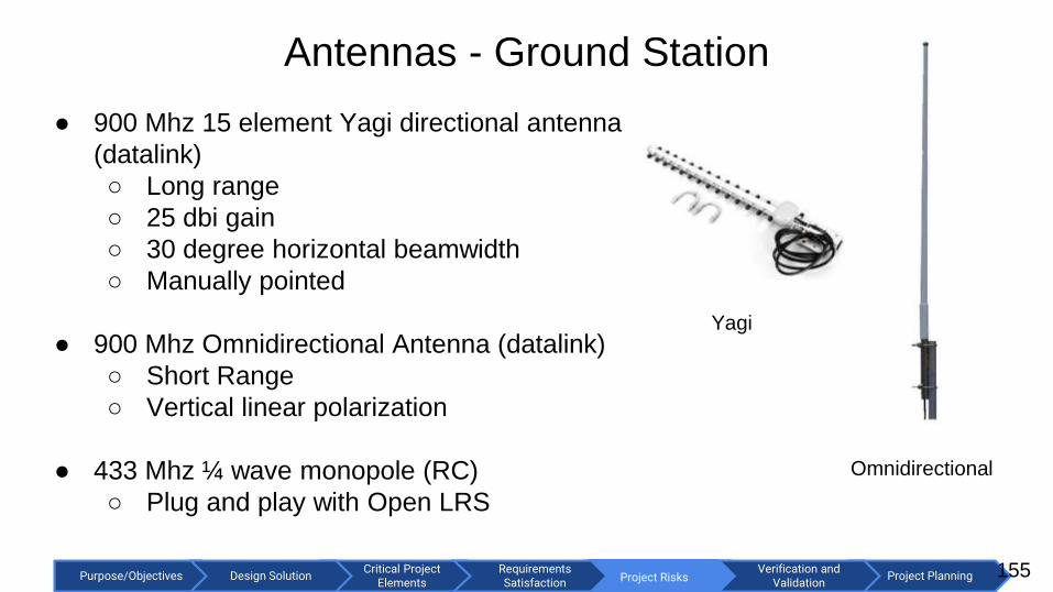
Critical Project Elements
Purpose/Objectives Design Solution Project RisksRequirements Satisfaction
Project PlanningVerification and
ValidationProject Risks
Antennas - Ground Station
155
● 900 Mhz 15 element Yagi directional antenna
(datalink)
○ Long range
○ 25 dbi gain
○ 30 degree horizontal beamwidth
○ Manually pointed
● 900 Mhz Omnidirectional Antenna (datalink)
○ Short Range
○ Vertical linear polarization
● 433 Mhz ¼ wave monopole (RC)
○ Plug and play with Open LRS
Yagi
Omnidirectional

Critical Project Elements
Purpose/Objectives Design Solution Project RisksRequirements Satisfaction
Project PlanningVerification and
ValidationProject Risks
Antennas - UAV
156
● 900 Mhz ¼ wave monopole (x2)
○ Vertical and horizontal linear
polarization
○ RP-SMA connectors
○ 2.1 dBi gain
● 433 Mhz ¼ wave monopole
○ Plug and play with OpenLRS

Critical Project Elements
Purpose/Objectives Design Solution Project RisksRequirements Satisfaction
Project PlanningVerification and
ValidationDesign Solutions
GNC comm
157
● How is each element communicating?
● ** Data rates

Critical Project Elements
Purpose/Objectives Design Solution Project RisksRequirements Satisfaction
Project PlanningVerification and
ValidationCritical Project
Elements
Aircraft Sizing
Subsystem Mass Fraction Mass (kg)
Structure .35
Electric Motor .05
Autopilot, Flight Computer,
RC electronics, Communication System
.05
Batteries 2.65 kg
Payload 2.00 kg
Known: battery mass (2.65 kg), payload weight (2.27 kg), mass fraction of structure, motor, small
electronics
158
Remaining Mass Fraction: 0.55
Current Mass: 4.65 kg

Critical Project Elements
Purpose/Objectives Design Solution Project RisksRequirements Satisfaction
Project PlanningVerification and
ValidationCritical Project
Elements
Requirement: The aircraft shall have a maximum takeoff weight at or under 22.7 kg.Aircraft Sizing
Subsystem Mass Fraction Mass (kg)
Structure 0.35 2.96 kg
Electric Motor 0.05 0.42 kg
Autopilot, Flight Computer,
RC electronics, Communication System
0.05 0.42 kg
Batteries 0.31 2.65 kg
Payload 0.24 2.00 kg
The aircraft mass 8.45 kg < 22.7 kg maximum ∴ Feasible
159

Critical Project Elements
Purpose/Objectives Design Solution Project RisksRequirements Satisfaction
Project PlanningVerification and
ValidationCritical Project
Elements
Center of Gravity & Fuselage LayoutRequirement: Aircraft supports downward-facing 2.0 kg simulated
instrument payload with 15 cm x 15 cm x 23 cm dimensions.
Payload Bay has access to
downward panel and has
dimensions
15 cm x 15 cm x 23 cm.
Previous slide shows 2.0 kg mass
in weight budget.
∴ Feasible
160
Center of Gravity
Neutral Point

Critical Project Elements
Purpose/Objectives Design Solution Project RisksRequirements Satisfaction
Project PlanningVerification and
ValidationCritical Project
Elements
Center of Gravity & Fuselage Layout
161
● Neutral Point: 72.8 cm from nose (25%
Mean aerodynamic chord)
● Need CG in front of neutral point
● Components can be moved into tailcone,
giving a CG range of 9 cm (61.6 cm -
70.6 cm)
Top Down

Critical Project Elements
Purpose/Objectives Design Solution Project RisksRequirements Satisfaction
Project PlanningVerification and
ValidationCritical Project
Elements162
Center of Gravity & Fuselage Layout
Center of Gravity
Neutral Point

Critical Project Elements
Purpose/Objectives Design Solution Project RisksRequirements Satisfaction
Project PlanningVerification and
ValidationCritical Project
Elements
Wing Area and Aspect Ratio
163
● Wing area S = 0.93 m2
○ W = 84.9 N (Total aircraft mass = 8.45 kg)
○ Stall speed Vs = 11.0 m/s
○ (CL)max ≅ 1.2
■ Reynolds number
● Aspect ratio based on span limit of 3 m → AR = 10.0
Wing area and coefficient of lift satisfy
stall requirement of 11 m/s

Critical Project Elements
Purpose/Objectives Design Solution Project RisksRequirements Satisfaction
Project PlanningVerification and
ValidationCritical Project
Elements
Wing Sweep
https://img.banggood.com/thumb/water/oaupload/ban
ggood/images/FA/F6/22135daa-d191-6ecd-fa67-
252ce7a3dd1b.jpghttps://img.newatlas.com/insitu-scaneagle2-
1.png?auto=format%2Ccompress&fit=max&h=670&q=60&w=1000&s=19accc2dfdc8
f20c1330a8264063b3e0
https://i-hls.com/wp-content/uploads/2013/08/Picture12.jpg
http://nick-stevens.com/wp-
content/uploads/2016/12/marswing_ortho_setx.jpg
164
● Helps satisfy
stability and
controllability
requirements
● Similar aircraft
with similar flight
missions

Critical Project Elements
Purpose/Objectives Design Solution Project RisksRequirements Satisfaction
Project PlanningVerification and
ValidationCritical Project
Elements
Layout
165

Critical Project Elements
Purpose/Objectives Design Solution Project RisksRequirements Satisfaction
Project PlanningVerification and
ValidationCritical Project
Elements
L/D
● Historical data (RECUV aircraft and AAA)
● OpenVSP model: L/Dcruise = 16.2 (Hoerner
estimation)
● CL at cruise speed:
● L/D at cruise:
Requirement: The aircraft shall have an L/D of at least 12.
The aircraft L/D is 16.2 >> 12, comfortable safety factor
considering calculation fidelity
∴ Feasible
166
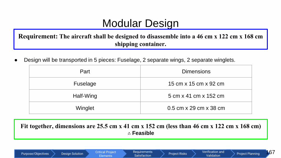
Critical Project Elements
Purpose/Objectives Design Solution Project RisksRequirements Satisfaction
Project PlanningVerification and
ValidationCritical Project
Elements
Modular Design
● Design will be transported in 5 pieces: Fuselage, 2 separate wings, 2 separate winglets.
Part Dimensions
Fuselage 15 cm x 15 cm x 92 cm
Half-Wing 5 cm x 41 cm x 152 cm
Winglet 0.5 cm x 29 cm x 38 cm
Requirement: The aircraft shall be designed to disassemble into a 46 cm x 122 cm x 168 cm
shipping container.
Fit together, dimensions are 25.5 cm x 41 cm x 152 cm (less than 46 cm x 122 cm x 168 cm) ∴ Feasible
167

Critical Project Elements
Purpose/Objectives Design Solution Project RisksRequirements Satisfaction
Project PlanningVerification and
ValidationCritical Project
Elements
Aircraft Stability (half scale)- AVL/Matlab
● Longitudinal eigenvalue
locus plot (half scale
model)
○ Range of C.G. :
approx. 31.5 +/- 7 cm
168
Short period mode - very stable
Phugoid mode - slightly stable for C.G.
range of 25.3 cm - 38.2 cm.
∴ Half-scale has similar longitudinal
stability as full scale, Feasible

Critical Project Elements
Purpose/Objectives Design Solution Project RisksRequirements Satisfaction
Project PlanningVerification and
ValidationCritical Project
Elements
Aircraft Stability (half scale)- AVL/Matlab
● Lateral eigenvalue locus
plot (half scale model)
○ Range of C.G. :
approx. 31.5 +/- 7 cm
169
Roll mode - very stable
Dutch roll; Spiral modes - slightly
stable for C.G. range of 25.3 cm - 38.2
cm.
∴ Half-scale has similar lateral
stability as full scale, Feasible
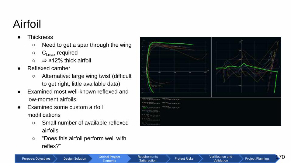
Critical Project Elements
Purpose/Objectives Design Solution Project RisksRequirements Satisfaction
Project PlanningVerification and
ValidationCritical Project
Elements
Airfoil
170
● Thickness
○ Need to get a spar through the wing
○ CLmax required
○ ⇒ ≥12% thick airfoil
● Reflexed camber
○ Alternative: large wing twist (difficult
to get right, little available data)
● Examined most well-known reflexed and
low-moment airfoils.
● Examined some custom airfoil
modifications
○ Small number of available reflexed
airfoils
○ “Does this airfoil perform well with
reflex?”

Critical Project Elements
Purpose/Objectives Design Solution Project RisksRequirements Satisfaction
Project PlanningVerification and
ValidationCritical Project
Elements
Airfoil
171
● Joukowski with Horten camber line (12% thickness, 2% camber)

Critical Project Elements
Purpose/Objectives Design Solution Project RisksRequirements Satisfaction
Project PlanningVerification and
ValidationCritical Project
Elements
Aircraft Stability- XFLR5
● Longitudinal eigenvalue
plot
172

Critical Project Elements
Purpose/Objectives Design Solution Project RisksRequirements Satisfaction
Project PlanningVerification and
ValidationCritical Project
Elements
Aircraft Stability- XFLR5
● Lateral eigenvalue plot
173

Critical Project Elements
Purpose/Objectives Design Solution Project RisksRequirements Satisfaction
Project PlanningVerification and
ValidationCritical Project
Elements
MBF Equation
174

Critical Project Elements
Purpose/Objectives Design Solution Project RisksRequirements Satisfaction
Project PlanningVerification and
ValidationCritical Project
Elements
Wing Structure Modeling
● Wing load distribution at 5
g (Prandtl Lifting Line
Theory) → 4th order
method.
● Looking at carbon spar,
EPP foam core, plastic skin.
○ Considering composite
skin.
Requirement: The aircraft shall have an operational g-limit of 5 g.
175

Critical Project Elements
Purpose/Objectives Design Solution Project RisksRequirements Satisfaction
Project PlanningVerification and
ValidationRequirements Satisfaction
Spring Constant Calculation model
176