cesrta ec build-up and mitigation program - introduction mark palmer june 25, 2009
TRANSCRIPT

CesrTA EC Build-Up and Mitigation Program - Introduction
Mark Palmer
June 25, 2009

June 25, 2009 CTA09 2
EC Build-Up Studies
• Goals:– Instrument key regions in CESR to characterize EC around
ring as input for characterizing beam-cloud interactions• Drifts• Dipoles• Quadrupoles• Wigglers
– Validate EC Build-up simulations against detailed experiments
– Develop instrumentation and techniques that can be used to study the efficacy of proposed EC mitigation techniques for the ILC DR

June 25, 2009 CTA09 3
ILCDR Proposed Mitigation Table
DR element % ring Antechamber Coating Additional Mitigation
Remarks
DRIFT in STRAIGHT
33 No NEG Solenoid Groove if necessary
DRIFT in ARC
56 Downstream of BEND only
NEG Solenoid Groove if necessary
BEND 7 Yes TiN Grooves and Electrodes
WIGG 3 Yes TiN Electrodes and Grooves
QUAD 1 Downstream BEND / WIGG
TiN Grooves and Electrodes
M. Pivi

June 25, 2009 CTA09 4
EC Mitigation Studies
• Goals:– Short-term: Verify efficacy of proposed mitigation
methods• Principal focus is to validate mitigation techniques in
wigglers and dipoles• Perform testing of newly proposed mitigations wherever
these fit within the program
– Long-term:• Where questions exist about the durability of proposed
mitigations (particularly coatings), hope to support long-term testing parasitic with an ongoing CHES program
• Provide inputs to the ILCDR engineering design

June 25, 2009 CTA09 5
Experimental Regions• L3 EC experimental region
PEP-II EC Hardware: Chicane, upgraded SEY station (coming on line in May)
Drift and Quadrupole diagnostic chambers
• New EC experimental regions in arcs (wigglers L0 straight)
Locations for collaborator experimental chambers
• CHESS C-line & D-line UpgradesWindowless (all vacuum) x-ray lineupgrade
Dedicated optics box at start of each line
Detectors share space in CHESS userhutches
• L0 region reconfigured as a wiggler straight
CLEO detector sub-systems removed
6 wigglers moved from CESR arcs tozero dispersion straight
Region instrumented with ECdiagnostics and mitigation
Wiggler chambers with retarding field analyzers and various EC mitigation methods (fabricated at LBNL in CU/SLAC/KEK/LBNL collaboration)
CESRRing

June 25, 2009 CTA09 6
Tools
• Have developed thin RFA structures– ~3mm thickness– Capable of fitting in standard dipole, wiggler,
quadrupole chambers– Sacrifice some characteristics to ensure ability to
characterize cloud in key regions• Typically single grid structures• Limited voltage range• Some care required with efficiency curve
• Custom readout electronics and DAQ to allow simultaneous monitoring of full ring
• TE Wave measurements to cross-check

June 25, 2009 CTA09 7
CESR Dipole
• Thin structure developed for use in limited aperture locations – CESR dipoles
– CESR-c wigglers
• Application to standard CESR VC (dipole & drift)
June 25, 2009 CTA09 8
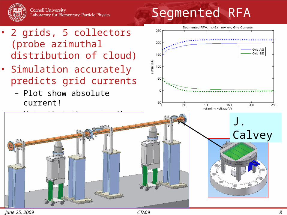
Segmented RFA
• 2 grids, 5 collectors (probe azimuthal distribution of cloud)
• Simulation accurately predicts grid currents– Plot show absolute current!– Note that the retarding grid
current goes negative in the data
J. Calvey

June 25, 2009 CTA09 9
Arc Regions
• 2 standard CESR VC RFAs deployed in dipole and drift regions in CESR– 9 transverse collectors– 3 transverse grids– Specifically Al chambers– Provide characterization of CESR arc cell
• Segmented RFAs– 5 transverse collectors– 2 grids (gnd + retarding in normal operation)– 4 units deployed in CESR Arcs
• APS-Cornell comparison• Cu vs TiN comparison
• Experimental chamber locations (Q15E/W)

June 25, 2009 CTA09 10
Wiggler RFAs
• Cu, TiN, Groove• Electrode version in design
Grooved Insert forCesrTA Wiggler
@LBNL
June 25, 2009 CTA09 11
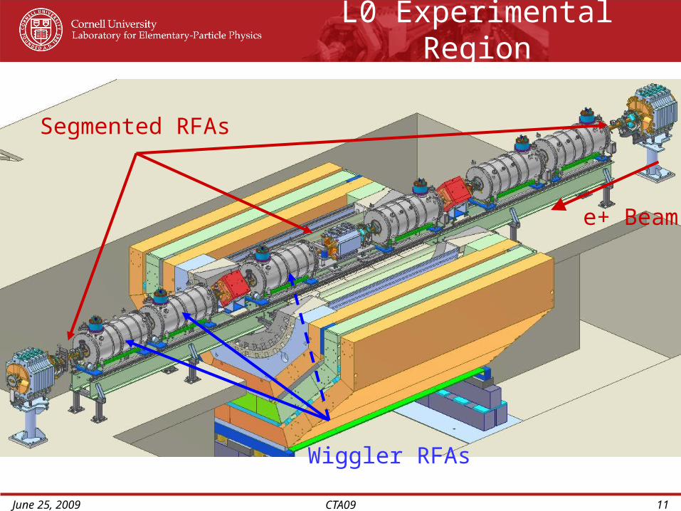
L0 Experimental Region
Segmented RFAs
Wiggler RFAs
e+ Beam

June 25, 2009 CTA09 12
L0 Region Summary
• 2 (3) Diagnostic wigglers– TiN and Cu VCs– 3rd wiggler with grooves to be installed next month– Each wiggler equipped with 3 RFAS
• 12 transverse collectors• 1 grid• Located at
– Center of pole– Roll-off region– Pole boundary
• 3 Segmented RFAs in adjacent drifts– Each end of wiggler straight– Center of straight

June 25, 2009 CTA09 13
Application to CESR Large Bore Quadrupole
Beampipe with 1740 transmission holes
RFA grids with Hi-T meshes

June 25, 2009 CTA09 14
1740 0.75 mm dia holes
Q48W Chamber
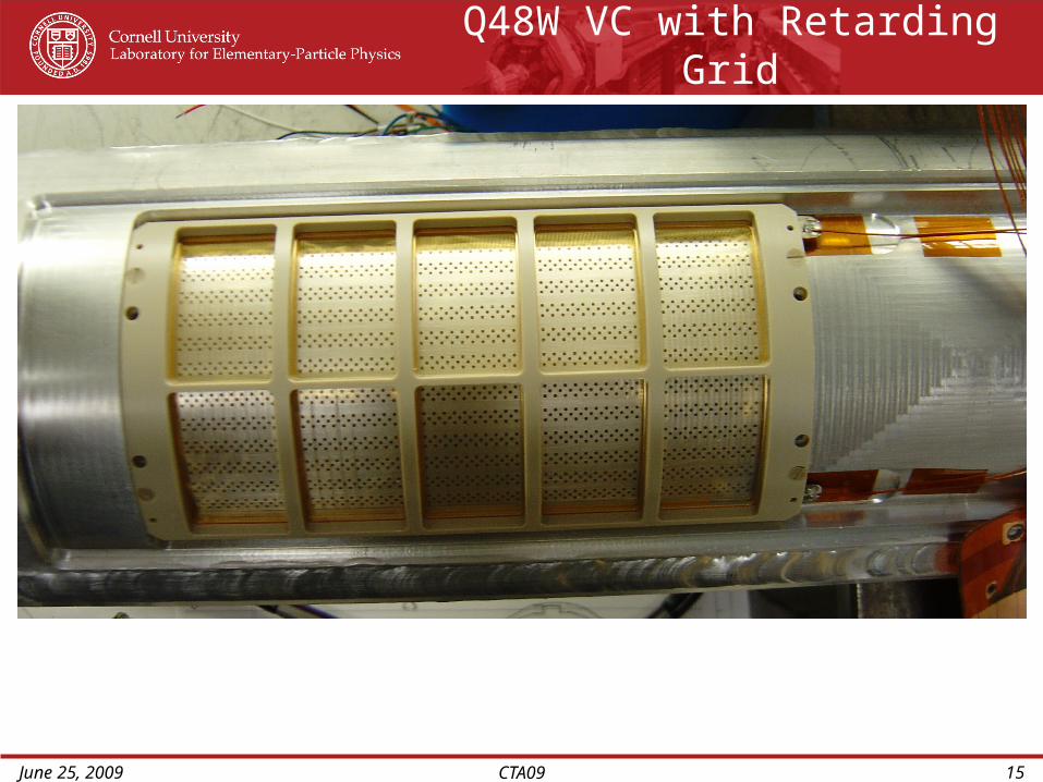
June 25, 2009 CTA09 15
Q48W VC with Retarding Grid

June 25, 2009 CTA09 16
L3 Experimental Region
e+ e-
West East
Ion Detector (ERL)
PEPII Chicane EC VC
SEY Station
Configured forIn Situ SEYMeasurements
Sample
Sample 1: Radial outsideSample 2: 45° from radial outside

June 25, 2009 CTA09 17
L3 Experimental Region Summary
• Presently have:– 3 SLAC RFAs in chicane
• 17 transverse collectors• 3 grids (2 gnd + retarding grid in middle)
– 4th SLAC RFA to be installed with grooved test chamber next month
– Quadrupole RFA• 12 transverse collectors• 1 retarding grid• To be installed next month
– SEY station – in testing– Room for additional experimental chambers