certificates of competency in the merchant navy · pdf filecertificates of competency in the...
TRANSCRIPT

CERTIFICATES OF COMPETENCY IN THE MERCHANT NAVY –
MARINE ENGINEER OFFICER
EXAMINATIONS ADMINISTERED BY THE
SCOTTISH QUALIFICATIONS AUTHORITY
ON BEHALF OF THE
MARITIME AND COASTGUARD AGENCY
STCW 95 CHIEF ENGINEER REG. III/2 (UNLIMITED)
041-31 – APPLIED MECHANICS
TUESDAY, 11 DECEMBER 2012
1315 - 1615 hrs
Examination paper inserts:
Notes for the guidance of candidates:
Materials to be supplied by colleges:
Candidate’s examination workbook
Graph paper
1. Non-programmable calculators may be used.
2. All formulae used must be stated and the method of working and ALL intermediate steps must
be made clear in the answer.


[OVER
APPLIED MECHANICS
Attempt SIX questions only
All questions carry equal marks
Marks for each part question are shown in brackets
1. A flat plate in a boiler is supported by bar stays. Each stay is 40 mm diameter, 0.8 m long
and supports a plate area of 0.4 m2. The internal pressure is 6 bar.
Calculate EACH of the following:
(a) the stress in each stay;
(b) the strain energy in each stay;
(c) the strain energy in a hollow stay of the same length and external diameter but an
internal diameter of 18 mm.
Note: Modulus of Elasticity for stay material = 190 GN/m2.
(4)
(6)
(6)
2. A set of shear legs arranged as shown in Fig Q2 is used to lift a load of 200 kg.
Determine EACH of the following:
(a) the load in each front leg;
(b) the load in the back-stay, stating whether this is compressive or tensile.
(12)
(4)
Fig Q2
3m
5 m 3.2 m 1.8 m

3. A welded pressure vessel of circular cross section has an oblique welded seam at an angle
of 60° to the longitudinal joint. The internal diameter of the pressure vessel is 1.9 m, the
shell plate thickness is 32 mm and the working pressure is 28 bar.
(a) Sketch the Forces normal and tangential to the longitudinal joint and the Forces
normal and tangential to the oblique seam.
(b) Calculate EACH of the following:
(i) the tensile stress normal to the circumferential seam;
(ii) the tensile stress normal to the oblique seam;
(iii) the percentage increase in the stress normal to the oblique seam if corrosion leads
to a 10% reduction in shell thickness at the seam.
(4)
(2)
(5)
(5)
4. An intermediate shaft is fitted to an engine of power 14 MW operating at 100 rev/min.
The shaft is to be solid, with a coupling flange at each end with 12 bolt holes on a pitch
circle diameter of 1.6 times the shaft diameter. The limiting shear stress is 190 MN/m2 for
the shaft material and 170 MN/m2 for the bolt material.
Calculate EACH of the following:
(a) the diameter of the shaft for a safety coefficient (factor of safety) of two;
(b) the diameter of the bolts for a safety coefficient (factor of safety) of two.
(8)
(8)
5. A vehicle travels around a bend on a banked track at a constant speed of 25 m/s and at an
effective radius of 100 m. The vehicle has a wheel base width of 1.6 metres and a centre
of gravity 1.4 metres above the track surface.
Calculate EACH of the following:
(a) the minimum angle of banking required to prevent the vehicle from overturning;
(b) the minimum coefficient of friction between the track and the vehicle to prevent the
vehicle sliding when the track is banked at the angle calculated in Q5(a).
(10)
(6)

[OVER
6. A Porter governor has arms of equal length 320 mm and two rotating masses of 0.8 kg
each. At the mean speed of 120 rev/min, with the speed falling, both sets of arms are at
30 degrees to the vertical. Friction at the central sleeve is constant at 20N.
Calculate EACH of the following:
(a) the central sleeve mass;
(b) the speed that would cause the sleeve to rise 20 mm from the mean speed position
given;
(c) the speed that would cause the sleeve to fall 20 mm from the mean speed position
given.
(8)
(5)
(3)
7. An engine fuel injector is operated by fuel oil pressure acting on the underside of a needle
valve. Movement of the needle valve is opposed by a spring with 14 coils of outside
diameter 22 mm and wire diameter 6 mm. Fuel oil pressure acts on an effective area of
34 mm2
on the underside of the needle valve. Fuel injection should not commence until
the fuel pressure has risen to 26 MN/m2. Valve lift is limited to 0.8 mm.
Calculate EACH of the following:
(a) the required initial axial compression of the spring;
(b) the maximum force on the spring;
(c) the maximum torsional stress in the spring.
Note: Modulus of Rigidity for spring material = 80 GN/m2
(8)
(4)
(4)
8. A regular cube of sides 100 mm floats vertically in a tank containing two immiscible
liquids of densities 800 kg/m3 and 1000 kg/m
3.
Calculate EACH of the following:
(a) the depth of the lighter liquid if 10 mm of the cube remains above the liquid surface;
(b) the mass of steel which should be attached to the base of the cube to ensure that the
cube is just submerged.
Note: Density of Cube material = 850 kg/m3
Density of Steel = 7800 kg/m3
(10)
(6)

9. A pump has a suction lift of 0.5 m and delivers 24 tonnes per hour of fresh water to a tank
whose water level is 16 m above the pump. The delivery pipe is 28 m long and 90 mm
bore, with a friction coefficient of 0.02.
Calculate EACH of the following:
(a) the power output of the pump;
(b) the pump discharge pressure.
Note: Assume the friction loss in the suction pipeline is negligible.
(10)
(6)

CERTIFICATES OF COMPETENCY IN THE MERCHANT NAVY –
MARINE ENGINEER OFFICER
EXAMINATIONS ADMINISTERED BY THE
SCOTTISH QUALIFICATIONS AUTHORITY
ON BEHALF OF THE
MARITIME AND COASTGUARD AGENCY
STCW 95 CHIEF ENGINEER REG. III/2 (UNLIMITED)
041-31 – APPLIED MECHANICS
TUESDAY, 16 OCTOBER 2012
1315 - 1615 hrs
Examination paper inserts:
Notes for the guidance of candidates:
Materials to be supplied by colleges:
Candidate’s examination workbook
Graph paper
1. Non-programmable calculators may be used.
2. All formulae used must be stated and the method of working and ALL intermediate steps must
be made clear in the answer.


[OVER
APPLIED MECHANICS
Attempt SIX questions only
All questions carry equal marks
Marks for each part question are shown in brackets
1. A steel shaft 240mm outside diameter is 2 m long. The shaft is solid for 0.8 m of its
length and hollow for the remainder, with an inside diameter of 160 mm. The shaft is
fixed at both ends and a torque of 25 kNm is applied at the junction of the solid and hollow
sections.
Calculate the maximum shear stress in the shaft material.
(16)
2. A solid rectangular section beam is loaded as shown in Fig Q2. It is simply supported at
points B and D and carries a uniformly distributed load of 6 kN/m over a 3 m length from
A to C. The breadth of the beam is 80 mm and the maximum stress due to bending is not
to exceed 140 MN/m2.
(a) Sketch the shear force diagram, indicating the values of shear force at points A, B, C
and D.
(b) Sketch the bending moment diagram, stating the maximum bending moment and
where it occurs.
(c) Calculate the minimum allowable depth of the beam.
(4)
(6)
(6)
Fig Q2
1.5 m
D C B A
50 kN UDL = 6 kN/m
1.5 m 2 m

3. An overhead camshaft operated valve moves with Simple Harmonic Motion. The valve
lift is 40 mm and the valve is opened and closed within 120° of camshaft rotation. The
mass of the valve is 0.8 kg. The valve moves against a spring and the maximum and
minimum spring forces are 900 N and 180 N respectively. The camshaft speed is
480 rev/min.
Calculate EACH of the following:
(a) the maximum velocity of the valve;
(b) the maximum acceleration of the valve;
(c) the force between the valve and the cam when the valve first starts to open;
(d) the force between the valve and the cam when the valve is fully open.
(4)
(2)
(5)
(5)
4. A winch drum has a mass of 300 kg and a radius of gyration of 320 mm. The winch has a
single brake shoe acting on a brake drum of 0.4 m diameter. The coefficient of friction
between the shoe and the drum is 0.8. Friction in the winch bearings is constant at 4 Nm.
Calculate EACH of the following:
(a) the force to be applied at the brake shoe to slow the winch down from 240 rev/min to
120 rev/min in 30 seconds;
(b) the work done by the brake to bring the drum to rest from 240 rev/min using the brake
force calculated in Q4(a).
(10)
(6)
5. A Hartnell governor has three rotating balls each of mass 0.3 kg. The length of the ball
arms are 150 mm and the length of the sleeve arms are 100 mm. When at the mean speed
of 480 rev/min and rising the balls are at a radius of 110 mm. The governor spring
stiffness is 14 kN/m and friction at the sleeve is 50 N.
Calculate EACH of the following:
(a) the spring compression at the mean speed;
(b) the vertical movement of the sleeve if the speed increases by 5%.
(8)
(8)

[OVER
6. A short vertical hollow cylindrical column, 160 mm high and fixed at the base, is 70 mm
outside diameter and 8 mm thick. It carries concentrated loads of 10 kN and 6 kN as
shown in Fig Q6.
Calculate EACH of the following:
(a) the maximum compressive stress in the column;
(b) the maximum tensile stress in the column.
(8)
(8)
7. A horizontal nozzle is supplied with sea water at a gauge pressure of 5 bar. The water
inlet velocity may be assumed to be negligible. The nozzle has a diameter of 30 mm and a
coefficient of velocity of 0.95. Water from the nozzle then strikes a curved fixed vane that
deflects the water jet through 45°. Due to friction across the vane, the velocity of the
water leaving the fixed vane is 6% lower than the initial velocity of the jet.
Calculate EACH of the following:
(a) the velocity of the water jet leaving the nozzle;
(b) the magnitude and direction of the force exerted by the jet on the fixed vane.
Note: Density of sea water = 1025 kg/m3
(4)
(12)
160mm
45°
10kN
6kN
50mm 50mm
Fig Q6

8. Two oil tanks are separated by a vertical bulkhead fitted with a circular flap valve, 600 mm
diameter. The valve is hinged at its top edge, which is 2.5 m above the bottom of the tank.
Both tanks contain oil of relative density 0.9, one to a depth of 2.5 m, the other to a depth
of 3.2 m.
Calculate the horizontal force required at the bottom edge of the door to open the door
against the hydrostatic force.
(16)
9. A hydraulic control piston is shown in Fig Q9. The input piston of 20 mm diameter is
displaced by the input force P. The system is filled with an incompressible liquid and the
movement of the 80 mm diameter output piston is resisted by a spring of stiffness
60 kN/m.
Calculate the force P required to achieve a 40 mm movement of the input piston
Fig Q9
(16)
P
Vent
Output Piston
Input Piston

CERTIFICATES OF COMPETENCY IN THE MERCHANT NAVY –
MARINE ENGINEER OFFICER
EXAMINATIONS ADMINISTERED BY THE
SCOTTISH QUALIFICATIONS AUTHORITY
ON BEHALF OF THE
MARITIME AND COASTGUARD AGENCY
STCW 95 CHIEF ENGINEER REG. III/2 (UNLIMITED)
041-31 – APPLIED MECHANICS
TUESDAY, 27 MARCH 2012
1315 - 1615 hrs
Examination paper inserts:
Notes for the guidance of candidates:
Materials to be supplied by colleges:
Candidate’s examination workbook
Graph paper
1. Non-programmable calculators may be used.
2. All formulae used must be stated and the method of working and ALL intermediate steps must
be made clear in the answer.


[OVER
APPLIED MECHANICS
Attempt SIX questions only
All questions carry equal marks
Marks for each part question are shown in brackets
1. A shaft consists of a bronze sleeve 390 mm outside diameter shrunk onto a solid steel shaft
of 340 mm diameter. The shaft is to transmit a power of 4.8 MW at a speed of 120 rev/min.
Calculate EACH of the following:
(a) the torque transmitted by the bronze sleeve;
(b) the percentage of the total power which is transmitted by the steel.
Note: Modulus of Rigidity for Bronze = 40 GN/m2
Modulus of Rigidity for Steel = 80 GN/m2.
(12)
(4)
2. A hollow brass tube, 24 mm outside diameter and 12 mm inside diameter is 260 mm long
and at a temperature of 18°C. It is then heated to 180°C and then rigidly secured at each
end to prevent any contraction.
Calculate EACH of the following:
(a) the length of the tube immediately after heating;
(b) the temperature to which the tube must be cooled so that the stress in the brass is
55 MN/m2;
(c) the strain energy in the bar at this lower temperature.
Note: Modulus of Elasticity for Brass = 80 GN/m2
Coefficient of linear expansion of Brass = 16 x 10 -6
/ oC.
(3)
(8)
(5)
3. An electric motor is running at 1500 rev/min when the power is shut off. The total
frictional resistance to motion is equivalent to a torque of 6 Nm, and forty seconds later the
speed of the motor has fallen to 800 rev/min.
Calculate EACH of the following:
(a) the moment of inertia (I) of the motor;
(b) the total time taken to come to rest;
(c) the total number of revolutions made after the power is shut off before coming to rest.
(8)
(4)
(4)

4. A steel beam is 5 m long and has a symmetrical cross section shown in Fig Q4 and is
simply supported at each end. The weight of the beam itself is 480 N per metre length and
the maximum allowable bending stress for the beam is 110 MN/m2.
Calculate EACH of the following:
(a) the maximum additional uniformly distributed load which can be carried;
(b) the least radius of curvature when carrying the load in Q4(a).
Note: Modulus of Elasticity for Steel = 210 GN/m2
(13)
(3)
5. A ship heading due South at 9 knots sights another ship dead ahead at a distance of
5 nautical miles. The second ship is heading in a direction 40° East of North at 20 knots.
Calculate EACH of the following:
(a) the relative velocity of the second ship to the first ship;
(b) the distance of nearest approach of the two ships;
(c) the time taken to reach the point of nearest approach.
(8)
(4)
(4)
80mm
10mm
Fig Q4
Cross Section
(not to scale)
300mm
12mm
12mm

[OVER
6. In a four-ram hydraulic steering gear the centre line of the rams is 1.2 m from the
centreline of the rudder stock. The diameter of the rams is 280 mm and the diameter of
the rudder stock is 420 mm.
Movement of the rudder is limited to 35° on either side and the maximum allowable shear
stress in the rudder stock is 70 MN/m2.
Calculate EACH of the following:
(a) the maximum allowable torque on the rudder stock;
(b) the pressure to which the relief valves on the rams should be set.
(6)
(10)
7. A pressurised spherical tank 12 m diameter is partly filled with liquefied gas. The
pressure at the bottom of the tank is 820 kN/m2
(gauge) whilst that in the gas space at the
top of the tank is 780 kN/m2 (gauge).
Calculate EACH of the following:
(a) the depth of liquid in the tank;
(b) the weight of liquid in the tank.
Note:
Where r = radius of the sphere
h = depth of the segment
Relative density of liquefied gas = 0.52
(7)
(9)

8. Two bodies A and B are connected by a light cord over a frictionless pulley as shown in
Fig Q8. The mass of A is 100 kg, its weight acts at its geometric centre and it stands on a
rough inclined plane. Mass B is gradually increased until mass A overturns.
Calculate EACH of the following:
(a) the mass of B that will just cause A to overturn;
(b) the minimum value of the coefficient of friction between the plane and body A to
prevent sliding when A is about to overturn.
Fig Q8
(8)
(8)
9. A fire-fighting launch discharges three identical jets of sea water through 40 mm diameter
nozzles, each jet being inclined upwards at 40° to the horizontal. The discharge velocity
of the water is 42 m/s and the velocity at the suction side can be ignored.
Calculate EACH of the following:
(a) the vertical force created by the jets;
(b) the increase in the immersed volume of the launch due to the operation of the jets.
Note: Density of Sea Water = 1025 kg/m3
(10)
(6)

CERTIFICATES OF COMPETENCY IN THE MERCHANT NAVY –
MARINE ENGINEER OFFICER
EXAMINATIONS ADMINISTERED BY THE
SCOTTISH QUALIFICATIONS AUTHORITY
ON BEHALF OF THE
MARITIME AND COASTGUARD AGENCY
STCW 95 CHIEF ENGINEER REG. III/2 (UNLIMITED)
041-31 – APPLIED MECHANICS
TUESDAY, 17 JULY 2012
1315 - 1615 hrs
Examination paper inserts:
Notes for the guidance of candidates:
Materials to be supplied by colleges:
Candidate’s examination workbook
Graph paper
1. Non-programmable calculators may be used.
2. All formulae used must be stated and the method of working and ALL intermediate steps must
be made clear in the answer.


[OVER
APPLIED MECHANICS
Attempt SIX questions only
All questions carry equal marks
Marks for each part question are shown in brackets
1. A Porter governor has arms of equal length, three flyweights each of mass 3 kg and a
central mass of 18 kg. Friction at the sleeve is constant at 22 N.
Calculate the maximum and minimum speeds for a governor height of 120 mm.
(16)
2. A hollow propeller shaft of 380 mm outside diameter and 320 mm inside diameter runs at
90 rev/min and propels a ship through the water at 17 knots. The total resistance of the
ship through the water at this speed is 300 kN and the propeller efficiency is 78%.
Calculate EACH of the following:
(a) the power transmitted by the shaft;
(b) the angel of twist of the shaft per metre length in degrees;
(c) the maximum torsional stress in the shaft.
Note Modulus of Rigidity of Shaft Material 80 GN/m2
1 knot = 0.514 m/s
(6)
(6)
(4)
3. A short vertical column consists of a hollow steel tube of 52 mm outside diameter and
40 mm inside diameter with a concentric solid brass rod of 35 mm diameter within it. The
steel tube is 380 mm long and the brass rod is 1 mm shorter.
The maximum allowable stress in the brass rod is 55 MN/m2.
Calculate the maximum vertical compressive load that can be placed on the column.
Note: Modulus of Elasticity for Steel = 210 GN/m2
Modulus of Elasticity for Brass = 80 GN/m2
(16)

4. An “I” section beam as shown in Fig Q4 is simply supported at both ends. It carries a
uniformly distributed load of 6 kN/m along its entire length and has a concentrated load of
18 kN at mid-span. The safety coefficient (factor of safety) of the beam is limited to 4.
Determine the maximum permissible length of the beam.
Note: UTS of Beam Material = 120 MN/m2
Fig Q4
(16)
5. When subjected to a tensile load of 80 kN, a uniform metal rod 30 mm diameter and 3 m
long extends by 1.8 mm.
The unloaded rod is then placed vertically with its upper end fixed and a collar fitted at its
free lower end. A load mass is then allowed to drop onto the collar from a height of
180 mm, and the instantaneous extension of the rod is found to be 3.6 mm.
Calculate EACH of the following:
(a) the Modulus of Elasticity for the rod;
(b) the magnitude of the load mass.
(4)
(12)

[OVER
6. An engine has rotating parts of mass 160 kg with a radius of gyration of 0.5 m. The
frictional torque for the engine may be assumed constant at 8 Nm. It is to be accelerated
from rest to its full speed of 720 rev/min and then clutched on to a stationary pump having
rotating parts of mass 50 kg and radius of gyration 0.3 m.
Calculate EACH of the following:
(a) the driving torque required to accelerate the engine from rest to 720 rev/min in
15 seconds;
(b) the common speed of the engine and pump just after engagement;
(c) the loss of kinetic energy due to the clutching operation.
(6)
(5)
(5)
7. A connecting rod has a mass of 1.43 tonne, is 3 m long and its centre of gravity is 1.8 m
from the top. It is to be freely suspended from the crosshead bearing, with the bottom end
bearing removed.
Calculate EACH of the following:
(a) the horizontal force required at the lower end of the con-rod to hold the rod at 20o to
the centre-line of the engine;
(b) the magnitude and direction of the minimum force required at the lower end of the
con-rod to hold the rod at 20o to the centre-line of the engine;
(c) the magnitude and direction of the reaction at the crosshead for condition in Q7(b).
(5)
(5)
(6)
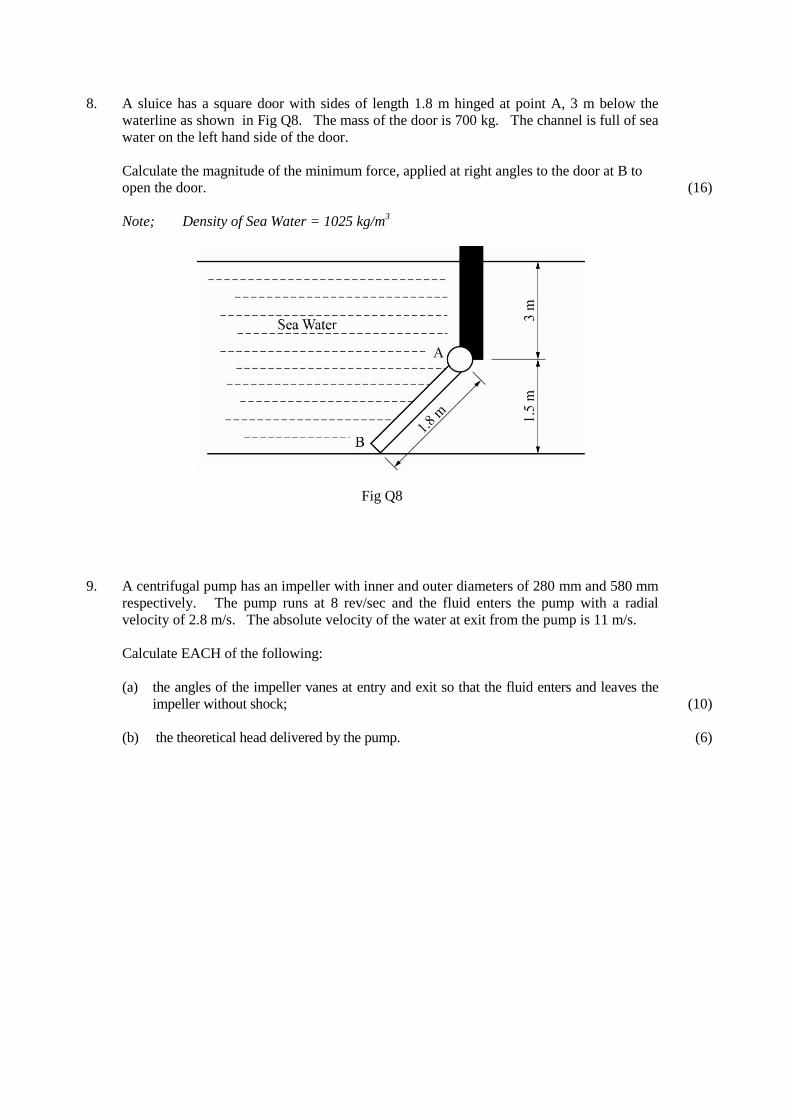
8. A sluice has a square door with sides of length 1.8 m hinged at point A, 3 m below the
waterline as shown in Fig Q8. The mass of the door is 700 kg. The channel is full of sea
water on the left hand side of the door.
Calculate the magnitude of the minimum force, applied at right angles to the door at B to
open the door.
Note; Density of Sea Water = 1025 kg/m3
Fig Q8
(16)
9. A centrifugal pump has an impeller with inner and outer diameters of 280 mm and 580 mm
respectively. The pump runs at 8 rev/sec and the fluid enters the pump with a radial
velocity of 2.8 m/s. The absolute velocity of the water at exit from the pump is 11 m/s.
Calculate EACH of the following:
(a) the angles of the impeller vanes at entry and exit so that the fluid enters and leaves the
impeller without shock;
(b) the theoretical head delivered by the pump.
(10)
(6)