certificate of accreditation - thomasnetcdn.thomasnet.com/ccp/10059667/55240.pdf · certificate of...
TRANSCRIPT
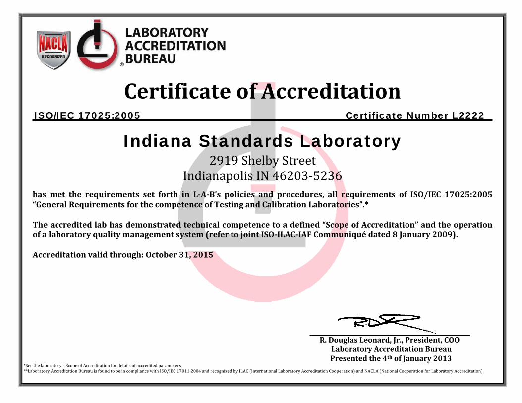
Certificate of Accreditation
ISO/IEC 17025:2005 Certificate Number L2222
Indiana Standards Laboratory 2919 Shelby Street
Indianapolis IN 46203-5236
has met the requirements set forth in L-A-B’s policies and procedures, all requirements of ISO/IEC 17025:2005 “General Requirements for the competence of Testing and Calibration Laboratories”.* The accredited lab has demonstrated technical competence to a defined “Scope of Accreditation” and the operation of a laboratory quality management system (refer to joint ISO-ILAC-IAF Communiqué dated 8 January 2009).
Accreditation valid through: October 31, 2015
R. Douglas Leonard, Jr., President, COO
Laboratory Accreditation Bureau Presented the 4th of January 2013 *See the laboratory’s Scope of Accreditation for details of accredited parameters **Laboratory Accreditation Bureau is found to be in compliance with ISO/IEC 17011:2004 and recognized by ILAC (International Laboratory Accreditation Cooperation) and NACLA (National Cooperation for Laboratory Accreditation).
®
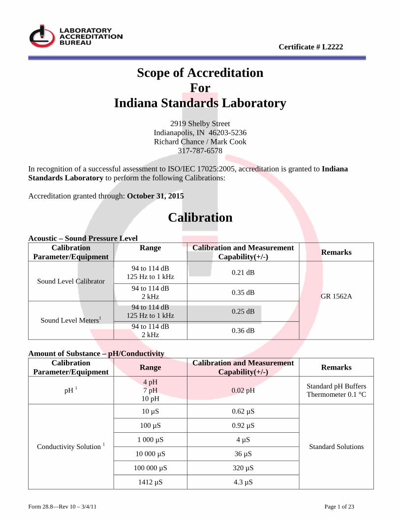
Certificate # L2222
Form 28.8—Rev 10 – 3/4/11 Page 1 of 23
Scope of Accreditation
For Indiana Standards Laboratory
2919 Shelby Street
Indianapolis, IN 46203-5236 Richard Chance / Mark Cook
317-787-6578 In recognition of a successful assessment to ISO/IEC 17025:2005, accreditation is granted to Indiana Standards Laboratory to perform the following Calibrations:
Accreditation granted through: October 31, 2015
Calibration Acoustic – Sound Pressure Level
Calibration Parameter/Equipment
Range
Calibration and Measurement Capability(+/-) Remarks
Sound Level Calibrator
94 to 114 dB 125 Hz to 1 kHz 0.21 dB
GR 1562A
94 to 114 dB 2 kHz 0.35 dB
Sound Level Meters1
94 to 114 dB 125 Hz to 1 kHz 0.25 dB
94 to 114 dB 2 kHz 0.36 dB
Amount of Substance – pH/Conductivity
Calibration Parameter/Equipment Range Calibration and Measurement
Capability(+/-) Remarks
pH 1 4 pH 7 pH 10 pH
0.02 pH Standard pH Buffers Thermometer 0.1 °C
Conductivity Solution 1
10 µS 0.62 µS
Standard Solutions
100 µS 0.92 µS
1 000 µS 4 µS
10 000 µS 36 µS
100 000 µS 320 µS
1412 µS 4.3 µS
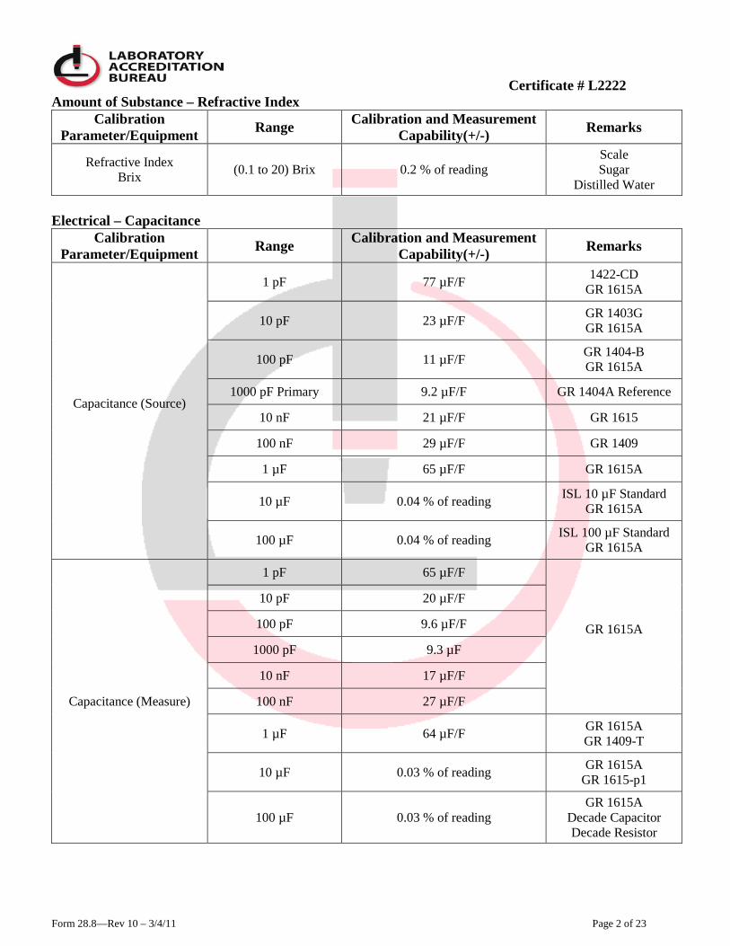
Certificate # L2222
Form 28.8—Rev 10 – 3/4/11 Page 2 of 23
Amount of Substance – Refractive Index Calibration
Parameter/Equipment Range Calibration and Measurement Capability(+/-) Remarks
Refractive Index Brix (0.1 to 20) Brix 0.2 % of reading
Scale Sugar
Distilled Water Electrical – Capacitance
Calibration Parameter/Equipment Range Calibration and Measurement
Capability(+/-) Remarks
Capacitance (Source)
1 pF 77 µF/F 1422-CD GR 1615A
10 pF 23 µF/F GR 1403G GR 1615A
100 pF 11 µF/F GR 1404-B GR 1615A
1000 pF Primary 9.2 µF/F GR 1404A Reference
10 nF 21 µF/F GR 1615
100 nF 29 µF/F GR 1409
1 µF 65 µF/F GR 1615A
10 µF 0.04 % of reading ISL 10 µF Standard GR 1615A
100 µF 0.04 % of reading ISL 100 µF Standard GR 1615A
Capacitance (Measure)
1 pF 65 µF/F
GR 1615A
10 pF 20 µF/F
100 pF 9.6 µF/F
1000 pF 9.3 µF
10 nF 17 µF/F
100 nF 27 µF/F
1 µF 64 µF/F GR 1615A GR 1409-T
10 µF 0.03 % of reading GR 1615A GR 1615-p1
100 µF 0.03 % of reading GR 1615A
Decade Capacitor Decade Resistor
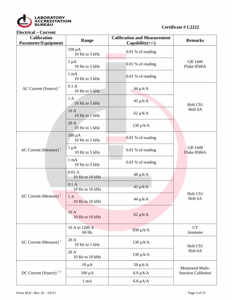
Certificate # L2222
Form 28.8—Rev 10 – 3/4/11 Page 3 of 23
Electrical – Current Calibration
Parameter/Equipment Range Calibration and Measurement Capability(+/-) Remarks
AC Current (Source) 1
100 µA 10 Hz to 5 kHz 0.01 % of reading
GR 1440 Fluke 8506A
1 µA 10 Hz to 5 kHz 0.01 % of reading
1 mA 10 Hz to 5 kHz 0.01 % of reading
0.1 A 10 Hz to 5 kHz 44 µA/A
Holt CS1 Holt 6A
1 A 10 Hz to 5 kHz 45 µA/A
10 A 10 Hz to 1 kHz 62 µA/A
20 A 10 Hz to 1 kHz 130 µA/A
AC Current (Measure) 1
100 µA 10 Hz to 5 kHz 0.01 % of reading
GR 1440 Fluke 8506A
1 µA 10 Hz to 5 kHz 0.01 % of reading
1 mA 10 Hz to 5 kHz 0.01 % of reading
AC Current (Measure) 1
0.01 A 10 Hz to 10 kHz 48 µA/A
Holt CS1 Holt 6A
0.1 A 10 Hz to 10 kHz 42 µA/A
1 A 10 Hz to 10 kHz 44 µA/A
10 A 10 Hz to 10 kHz 62 µA/A
AC Current (Measure) 1
10 A to 1200 A 60 Hz 830 µA/A CT
Ammeter
20 A 10 Hz to 1 kHz 130 µA/A
Holt CS1 Holt 6A 20 A
10 Hz to 10 kHz 130 µA/A
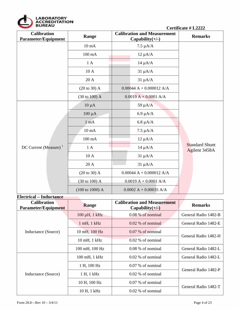
DC Current (Source) 1,3
10 µA 59 µA/A Monitored Multi-
function Calibrator
100 µA 6.9 µA/A
1 mA 6.8 µA/A
Certificate # L2222
Form 28.8—Rev 10 – 3/4/11 Page 4 of 23
Calibration Parameter/Equipment Range Calibration and Measurement
Capability(+/-) Remarks
10 mA 7.5 µA/A
100 mA 12 µA/A
1 A 14 µA/A
10 A 31 µA/A
20 A 31 µA/A
(20 to 30) A 0.00044 A + 0.000012 A/A
(30 to 100) A 0.0019 A + 0.0001 A/A
DC Current (Measure) 1
10 µA 59 µA/A
Standard Shunt Agilent 3458A
100 µA 6.9 µA/A
1 mA 6.8 µA/A
10 mA 7.5 µA/A
100 mA 12 µA/A
1 A 14 µA/A
10 A 31 µA/A
20 A 31 µA/A
(20 to 30) A 0.00044 A + 0.000012 A/A
(30 to 100) A 0.0019 A + 0.0001 A/A
(100 to 1000) A 0.0002 A + 0.00035 A/A
Electrical – Inductance Calibration
Parameter/Equipment Range Calibration and Measurement Capability(+/-) Remarks
Inductance (Source)
100 µH, 1 kHz 0.08 % of nominal General Radio 1482-B
1 mH, 1 kHz 0.02 % of nominal General Radio 1482-E
10 mH, 100 Hz 0.07 % of nominal General Radio 1482-H
10 mH, 1 kHz 0.02 % of nominal
100 mH, 100 Hz 0.08 % of nominal General Radio 1482-L
Inductance (Source)
100 mH, 1 kHz 0.02 % of nominal General Radio 1482-L
1 H, 100 Hz 0.07 % of nominal General Radio 1482-P
1 H, 1 kHz 0.02 % of nominal
10 H, 100 Hz 0.07 % of nominal General Radio 1482-T
10 H, 1 kHz 0.02 % of nominal

Certificate # L2222
Form 28.8—Rev 10 – 3/4/11 Page 5 of 23
Calibration Parameter/Equipment Range Calibration and Measurement
Capability(+/-) Remarks
Inductance (Measure)
100 µH, 1 kHz 0.1 % of reading
General Radio 1689
1 mH, 1 kHz 0.03 % of reading
10 mH, 100 Hz 0.09 % of reading
10 mH, 1 kHz 0.03 % of reading
100 mH, 100 Hz 0.09 % of reading
100 mH, 1 kHz 0.03 % of reading
1 H, 100 Hz 0.08 % of reading
1 H, 1 kHz 0.03 % of reading
10 H, 100 Hz 0.09 % of reading
10 H, 1 kHz 0.03 % of reading Electrical – Magnetic Properties
Calibration Parameter/Equipment Range Calibration and Measurement
Capability(+/-) Remarks
Magnetometers / Flux Meters
(0 to 20) G 0.014 G + 0.012 G/G
Gauss Meter With Transverse
Probe
(20 to 200) G 0.2 G + 0.0062G/G
(200 to 2000) G 2 G + 0.0063 G/G
(2000 to 20 000) G 20 G + 0.0063 G/G
Electrical – Resistance
Calibration Parameter/Equipment Range
Calibration and Measurement Capability(+/-)
Remarks
Resistance (Source) 1
100 µΩ 5 µΩ/Ω Otto Wolff 0.0001
1 mΩ 2.9 µΩ/Ω Leeds & Northrup 4223-B
10 mΩ 2.9 µΩ/Ω Leeds & Northrup 4222-B
100 mΩ 1.8 µΩ/Ω Leeds & Northrup 4221-B
1 Ω 0.64 µΩ/Ω Leeds & Northrup 4210
10 Ω 1.1 µΩ/Ω Leeds & Northrup 4025-B
100 Ω 0.63 µΩ/Ω Leeds & Northrup 4030-B
1 kΩ 1.2 µΩ/Ω Leeds & Northrup 4035-B
10 kΩ 1.7 µΩ/Ω Leeds & Northrup 4040-B
100 kΩ 2.3 µΩ/Ω Leeds & Northrup 4045-B
Certificate # L2222
Form 28.8—Rev 10 – 3/4/11 Page 6 of 23
Calibration Parameter/Equipment Range
Calibration and Measurement Capability(+/-)
Remarks
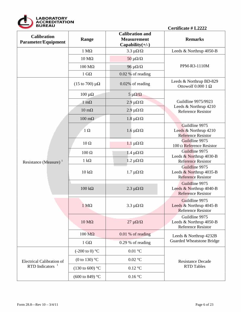
1 MΩ 3.3 µΩ/Ω Leeds & Northrup 4050-B
10 MΩ 50 µΩ/Ω
PPM-R3-1110M 100 MΩ 96 µΩ/Ω
1 GΩ 0.02 % of reading
Resistance (Measure) 1
(15 to 700) µΩ 0.02% of reading Leeds & Northrup BD-829 Ottowolf 0.000 1 Ω
100 µΩ 5 µΩ/Ω
Guildline 9975/9923 Leeds & Northrup 4210
Reference Resistor
1 mΩ 2.9 µΩ/Ω
10 mΩ 2.9 µΩ/Ω
100 mΩ 1.8 µΩ/Ω
1 Ω 1.6 µΩ/Ω Guildline 9975
Leeds & Northrup 4210 Reference Resistor
10 Ω 1.1 µΩ/Ω Guildline 9975 100 Ω Reference Resistor
100 Ω 1.4 µΩ/Ω Guildline 9975 Leeds & Northrup 4030-B
Reference Resistor 1 kΩ 1.2 µΩ/Ω
10 kΩ 1.7 µΩ/Ω Guildline 9975
Leeds & Northrup 4035-B Reference Resistor
100 kΩ 2.3 µΩ/Ω Guildline 9975
Leeds & Northrup 4040-B Reference Resistor
1 MΩ 3.3 µΩ/Ω Guildline 9975
Leeds & Northrup 4045-B Reference Resistor
10 MΩ 27 µΩ/Ω Guildline 9975
Leeds & Northrup 4050-B Reference Resistor
100 MΩ 0.01 % of reading Leeds & Northrup 4232B Guarded Wheatstone Bridge 1 GΩ 0.29 % of reading
Electrical Calibration of RTD Indicators 1
(-200 to 0) °C 0.01 °C
Resistance Decade RTD Tables
(0 to 130) °C 0.02 °C
(130 to 600) °C 0.12 °C
(600 to 849) °C 0.16 °C
Certificate # L2222
Form 28.8—Rev 10 – 3/4/11 Page 7 of 23
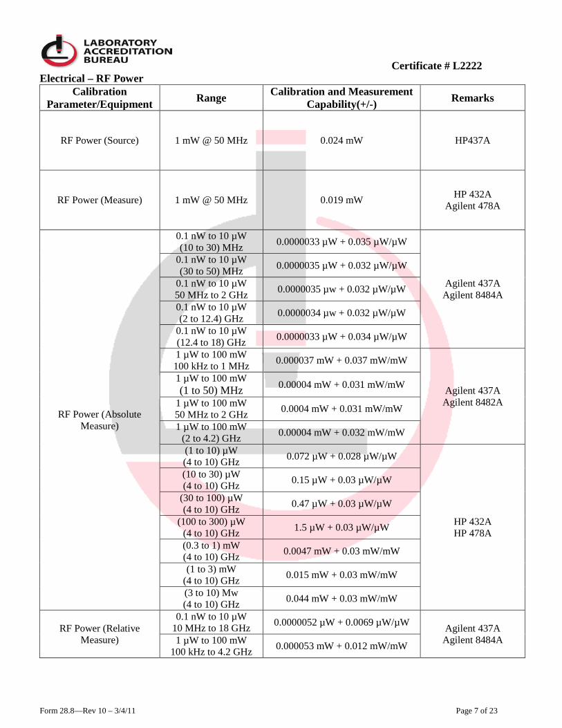
Electrical – RF Power Calibration
Parameter/Equipment Range Calibration and Measurement Capability(+/-) Remarks
RF Power (Source) 1 mW @ 50 MHz 0.024 mW HP437A
RF Power (Measure) 1 mW @ 50 MHz 0.019 mW HP 432A Agilent 478A
RF Power (Absolute Measure)
0.1 nW to 10 µW (10 to 30) MHz 0.0000033 µW + 0.035 µW/µW
Agilent 437A Agilent 8484A
0.1 nW to 10 µW (30 to 50) MHz 0.0000035 µW + 0.032 µW/µW
0.1 nW to 10 µW 50 MHz to 2 GHz 0.0000035 µw + 0.032 µW/µW
0.1 nW to 10 µW (2 to 12.4) GHz 0.0000034 µw + 0.032 µW/µW
0.1 nW to 10 µW (12.4 to 18) GHz 0.0000033 µW + 0.034 µW/µW
1 µW to 100 mW 100 kHz to 1 MHz 0.000037 mW + 0.037 mW/mW
Agilent 437A Agilent 8482A
1 µW to 100 mW (1 to 50) MHz 0.00004 mW + 0.031 mW/mW
1 µW to 100 mW 50 MHz to 2 GHz 0.0004 mW + 0.031 mW/mW
1 µW to 100 mW (2 to 4.2) GHz 0.00004 mW + 0.032 mW/mW
(1 to 10) µW (4 to 10) GHz 0.072 µW + 0.028 µW/µW
HP 432A HP 478A
(10 to 30) µW (4 to 10) GHz 0.15 µW + 0.03 µW/µW
(30 to 100) µW (4 to 10) GHz 0.47 µW + 0.03 µW/µW
(100 to 300) µW (4 to 10) GHz 1.5 µW + 0.03 µW/µW
(0.3 to 1) mW (4 to 10) GHz 0.0047 mW + 0.03 mW/mW
(1 to 3) mW (4 to 10) GHz 0.015 mW + 0.03 mW/mW
(3 to 10) Mw (4 to 10) GHz 0.044 mW + 0.03 mW/mW
RF Power (Relative Measure)
0.1 nW to 10 µW 10 MHz to 18 GHz 0.0000052 µW + 0.0069 µW/µW Agilent 437A
Agilent 8484A 1 µW to 100 mW 100 kHz to 4.2 GHz 0.000053 mW + 0.012 mW/mW
Certificate # L2222
Form 28.8—Rev 10 – 3/4/11 Page 8 of 23
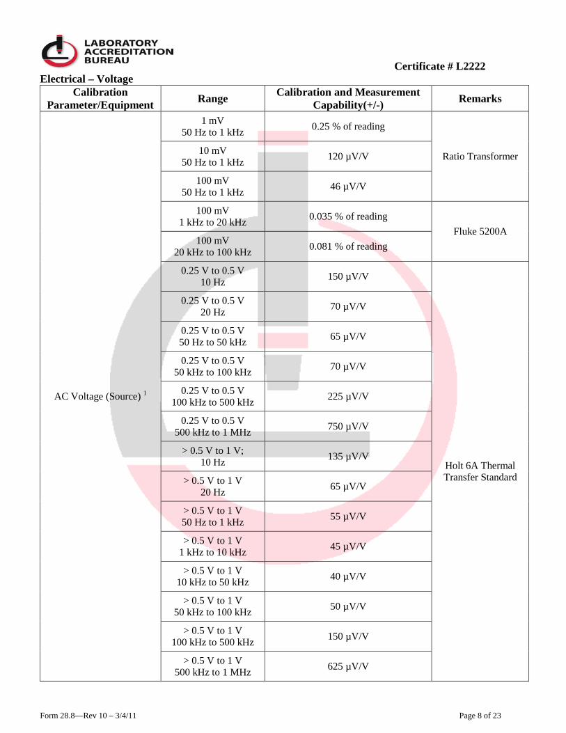
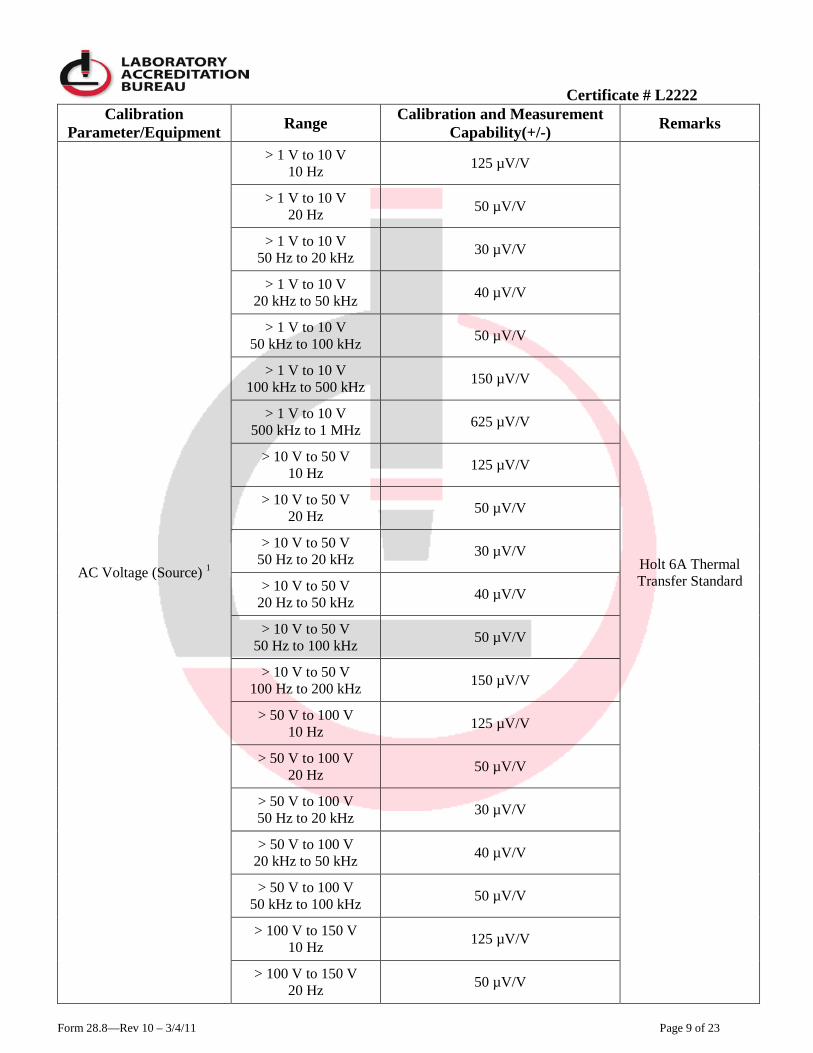
Electrical – Voltage Calibration
Parameter/Equipment Range Calibration and Measurement Capability(+/-) Remarks
AC Voltage (Source) 1
1 mV 50 Hz to 1 kHz 0.25 % of reading
Ratio Transformer 10 mV 50 Hz to 1 kHz 120 µV/V
100 mV 50 Hz to 1 kHz 46 µV/V
100 mV 1 kHz to 20 kHz 0.035 % of reading
Fluke 5200A 100 mV
20 kHz to 100 kHz 0.081 % of reading
0.25 V to 0.5 V 10 Hz 150 µV/V
Holt 6A Thermal Transfer Standard
0.25 V to 0.5 V 20 Hz 70 µV/V
0.25 V to 0.5 V 50 Hz to 50 kHz 65 µV/V
0.25 V to 0.5 V 50 kHz to 100 kHz 70 µV/V
0.25 V to 0.5 V 100 kHz to 500 kHz 225 µV/V
0.25 V to 0.5 V 500 kHz to 1 MHz 750 µV/V
> 0.5 V to 1 V; 10 Hz 135 µV/V
> 0.5 V to 1 V 20 Hz 65 µV/V
> 0.5 V to 1 V 50 Hz to 1 kHz 55 µV/V
> 0.5 V to 1 V 1 kHz to 10 kHz 45 µV/V
> 0.5 V to 1 V 10 kHz to 50 kHz 40 µV/V
> 0.5 V to 1 V 50 kHz to 100 kHz 50 µV/V
> 0.5 V to 1 V 100 kHz to 500 kHz 150 µV/V
> 0.5 V to 1 V 500 kHz to 1 MHz 625 µV/V
Certificate # L2222
Form 28.8—Rev 10 – 3/4/11 Page 9 of 23
Calibration Parameter/Equipment Range Calibration and Measurement
Capability(+/-) Remarks
AC Voltage (Source) 1
> 1 V to 10 V 10 Hz 125 µV/V
Holt 6A Thermal Transfer Standard
> 1 V to 10 V 20 Hz 50 µV/V
> 1 V to 10 V 50 Hz to 20 kHz 30 µV/V
> 1 V to 10 V 20 kHz to 50 kHz 40 µV/V
> 1 V to 10 V 50 kHz to 100 kHz 50 µV/V
> 1 V to 10 V 100 kHz to 500 kHz 150 µV/V
> 1 V to 10 V 500 kHz to 1 MHz 625 µV/V
> 10 V to 50 V 10 Hz 125 µV/V
> 10 V to 50 V 20 Hz 50 µV/V
> 10 V to 50 V 50 Hz to 20 kHz 30 µV/V
> 10 V to 50 V 20 Hz to 50 kHz 40 µV/V
> 10 V to 50 V 50 Hz to 100 kHz 50 µV/V
> 10 V to 50 V 100 Hz to 200 kHz 150 µV/V
> 50 V to 100 V 10 Hz 125 µV/V
> 50 V to 100 V 20 Hz 50 µV/V
> 50 V to 100 V 50 Hz to 20 kHz 30 µV/V
> 50 V to 100 V 20 kHz to 50 kHz 40 µV/V
> 50 V to 100 V 50 kHz to 100 kHz 50 µV/V
> 100 V to 150 V 10 Hz 125 µV/V
> 100 V to 150 V 20 Hz 50 µV/V

Certificate # L2222
Form 28.8—Rev 10 – 3/4/11 Page 10 of 23
Calibration Parameter/Equipment Range Calibration and Measurement
Capability(+/-) Remarks
AC Voltage (Source) 1
> 100 V to 150 V 50 Hz to 1 kHz 30 µV/V
Holt 6A Thermal Transfer Standard
> 100 V to 150 V 1 kHz to 10 kHz 40 µV/V
> 100 V to 150 V 10 kHz to 20 kHz 50 µV/V
> 100 V to 150 V 20 kHz to 50 kHz 65 µV/V
> 100 V to 150 V 50 kHz to 100 kHz 100 µV/V
> 150 V to 300 V 10 Hz 125 µV/V
> 150 V to 300 V 20 Hz 50 µV/V
> 150 V to 300 V 50 Hz to 1 kHz 30 µV/V
> 150 V to 300 V 1 kHz to 10 kHz 40 µV/V
> 150 V to 300 V 10 kHz to 20 kHz 50 µV/V
> 150 V to 300 V 20 kHz to 50 kHz 65 µV/V
> 300 V to 500 V 10 Hz 125 µV/V
> 300 V to 500 V 20 Hz 50 µV/V
> 300 V to 500 V 50 Hz to 1 kHz 35 µV/V
> 300 V to 500 V 1 kHz to 10 kHz 60 µV/V
> 300 V to 500 V 10 kHz to 20 kHz 90 µV/V
> 300 V to 500 V 20 kHz to 50 kHz 110 µV/V
> 500 V to 1200 V 10 Hz 125 µV/V
> 500 V to 1200 V 20 Hz 50 µV/V
> 500 V to 1200 V 50 Hz to 1 kHz 40 µV/V

Certificate # L2222
Form 28.8—Rev 10 – 3/4/11 Page 11 of 23
Calibration Parameter/Equipment Range Calibration and Measurement
Capability(+/-) Remarks
AC Voltage (Source) 1
> 500 V to 1200 V 1 kHz to 10 kHz 60 µV/V
Holt 6A Thermal Transfer Standard
> 500 V to 1200 V 10 kHz to 20 kHz 120 µV/V
> 500 V to 1200 V 20 kHz to 50 kHz 145 µV/V
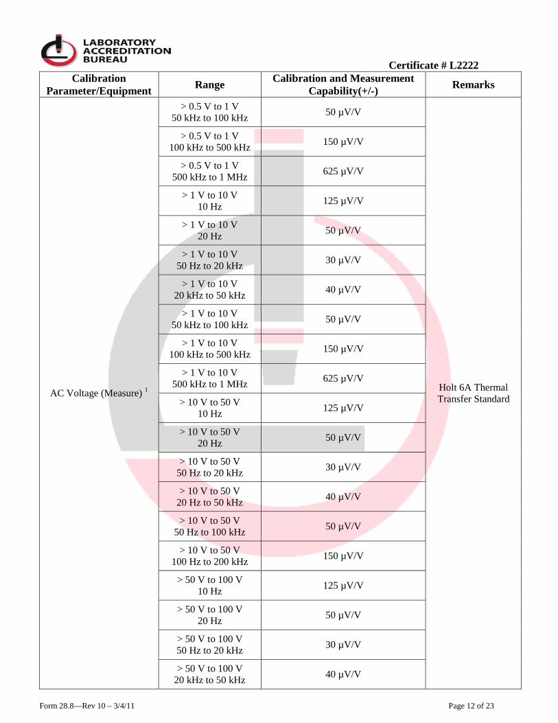
AC Voltage (Measure) 1
1 mV 50 Hz to 1 kHz 0.26 % of reading
Ratio Transformer 10 mV 50 Hz to 1 kHz 120 µV/V
100 mV 50 Hz to 1 kHz 49 µV/V
100 mV 1 kHz to 20 kHz 0.36 % of reading
Fluke 8506A 100 mV 20 kHz to 50 kHz 0.07 % of reading
100 mV 50 kHz to 100 kHz 0.23 % of reading
0.25 V to 0.5 V 10 Hz 150 µV/V
Holt 6A Thermal Transfer Standard
0.25 V to 0.5 V 20 Hz 70 µV/V
0.25 V to 0.5 V 50 Hz to 50 kHz 65 µV/V
0.25 V to 0.5 V 50 kHz to 100 kHz 70 µV/V
0.25 V to 0.5 V 100 kHz to 500 kHz 225 µV/V
0.25 V to 0.5 V 500 kHz to 1 MHz 750 µV/V
> 0.5 V to 1 V 10 Hz 135 µV/V
> 0.5 V to 1 V 20 Hz 65 µV/V
> 0.5 V to 1 V 50 Hz to 1 kHz 55 µV/V
> 0.5 V to 1 V 1 kHz to 10 kHz 45 µV/V
> 0.5 V to 1 V 10 kHz to 50 kHz 40 µV/V
Certificate # L2222
Form 28.8—Rev 10 – 3/4/11 Page 12 of 23
Calibration Parameter/Equipment Range Calibration and Measurement
Capability(+/-) Remarks
AC Voltage (Measure) 1
> 0.5 V to 1 V 50 kHz to 100 kHz 50 µV/V
Holt 6A Thermal Transfer Standard
> 0.5 V to 1 V 100 kHz to 500 kHz 150 µV/V
> 0.5 V to 1 V 500 kHz to 1 MHz 625 µV/V
> 1 V to 10 V 10 Hz 125 µV/V
> 1 V to 10 V 20 Hz 50 µV/V
> 1 V to 10 V 50 Hz to 20 kHz 30 µV/V
> 1 V to 10 V 20 kHz to 50 kHz 40 µV/V
> 1 V to 10 V 50 kHz to 100 kHz 50 µV/V
> 1 V to 10 V 100 kHz to 500 kHz 150 µV/V
> 1 V to 10 V 500 kHz to 1 MHz 625 µV/V
> 10 V to 50 V 10 Hz 125 µV/V
> 10 V to 50 V 20 Hz 50 µV/V
> 10 V to 50 V 50 Hz to 20 kHz 30 µV/V
> 10 V to 50 V 20 Hz to 50 kHz 40 µV/V
> 10 V to 50 V 50 Hz to 100 kHz 50 µV/V
> 10 V to 50 V 100 Hz to 200 kHz 150 µV/V
> 50 V to 100 V 10 Hz 125 µV/V
> 50 V to 100 V 20 Hz 50 µV/V
> 50 V to 100 V 50 Hz to 20 kHz 30 µV/V
> 50 V to 100 V 20 kHz to 50 kHz 40 µV/V
Certificate # L2222
Form 28.8—Rev 10 – 3/4/11 Page 13 of 23
Calibration Parameter/Equipment Range Calibration and Measurement
Capability(+/-) Remarks
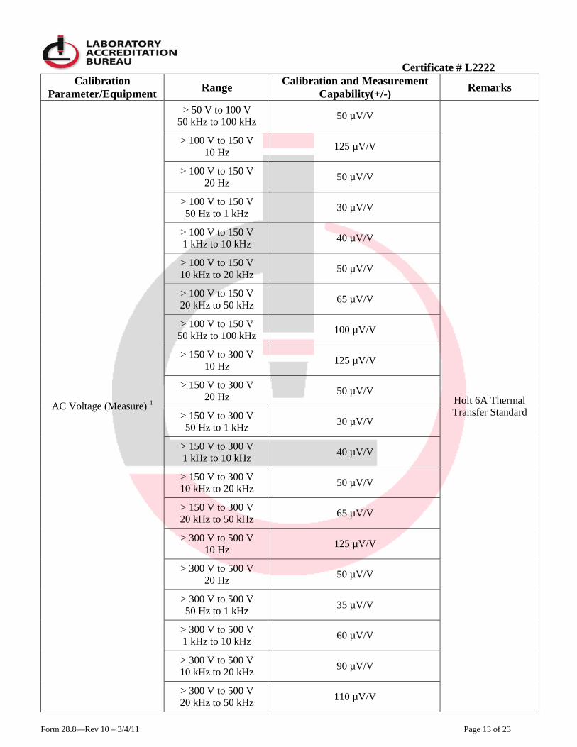
AC Voltage (Measure) 1
> 50 V to 100 V 50 kHz to 100 kHz 50 µV/V
Holt 6A Thermal Transfer Standard
> 100 V to 150 V 10 Hz 125 µV/V
> 100 V to 150 V 20 Hz 50 µV/V
> 100 V to 150 V 50 Hz to 1 kHz 30 µV/V
> 100 V to 150 V 1 kHz to 10 kHz 40 µV/V
> 100 V to 150 V 10 kHz to 20 kHz 50 µV/V
> 100 V to 150 V 20 kHz to 50 kHz 65 µV/V
> 100 V to 150 V 50 kHz to 100 kHz 100 µV/V
> 150 V to 300 V 10 Hz 125 µV/V
> 150 V to 300 V 20 Hz 50 µV/V
> 150 V to 300 V 50 Hz to 1 kHz 30 µV/V
> 150 V to 300 V 1 kHz to 10 kHz 40 µV/V
> 150 V to 300 V 10 kHz to 20 kHz 50 µV/V
> 150 V to 300 V 20 kHz to 50 kHz 65 µV/V
> 300 V to 500 V 10 Hz 125 µV/V
> 300 V to 500 V 20 Hz 50 µV/V
> 300 V to 500 V 50 Hz to 1 kHz 35 µV/V
> 300 V to 500 V 1 kHz to 10 kHz 60 µV/V
> 300 V to 500 V 10 kHz to 20 kHz 90 µV/V
> 300 V to 500 V 20 kHz to 50 kHz 110 µV/V

Certificate # L2222
Form 28.8—Rev 10 – 3/4/11 Page 14 of 23
Calibration Parameter/Equipment Range Calibration and Measurement
Capability(+/-) Remarks
AC Voltage (Measure) 1
> 500 V to 1200 V 10 Hz to 50 kHz 125 µV/V
Holt 6A Thermal Transfer Standard
> 500 V to 1200 V 20 Hz 50 µV/V
> 500 V to 1200 V 50 Hz to 1 kHz 40 µV/V
> 500 V to 1200 V 1 kHz to 10 kHz 60 µV/V
> 500 V to 1200 V 10 kHz to 20 kHz 120 µV/V
> 500 V to 1200 V 20 kHz to 50 kHz 145 µV/V
AC High Voltage (Source) (1 to 30) kV 1.2 % of reading Voltage Divider
Voltmeter High Voltage Source
AC High Voltage (Measure)
(1 to 5) kV 0.34 % of reading Voltage Divider
Voltmeter (5 to 30) kV 0.35 % of reading
(30 to 200) kV 1.2 % of reading
DC Voltage (Source) Lab Reference 10 V 3.5 µV/V Fluke 732A
DC Voltage (Source) 1
(10 to 100) µV 0.25 µV + 0.5% of reading Keithley 260
100 µV 4100 µV/V Fluke 732A Kelvin Varley
Divider 1 mV 480 µV/V
10 mV 13 µV/V
Fluke 732A Fluke 752A
100 mV 4.6 µV/V
1 V 3.5 µV/V
100 V 3.6 µV/V
1000 V 3.7 µV/V
DC High Voltage (Source) (1 to 70) kV 0.59 % of reading Voltmeter
Voltage Divider High Voltage Source
DC Voltage (Measure) 1
(0 to 100) µV
(3 % FS + 0.25 µV) Keithley 155 (0 to 10) µV
(0 to 1) µV

Certificate # L2222
Form 28.8—Rev 10 – 3/4/11 Page 15 of 23
Calibration Parameter/Equipment Range Calibration and Measurement
Capability(+/-) Remarks
DC Voltage (Measure) 1
100 µV 4500 µV/V Null Detector Kelvin Varley
Divider 1 mV 510 µV/V
10 mV 13 µV/V
Fluke 732A Fluke 752A
Reference Divider Null Detector
100 mV 4.9 µV/V
1 V 3.5 µV/V
10 V 3.5 µV/V
100 V 3.6 µV/V
1000 V 3.7 µV/V
DC High Voltage (Measure)
(1 to 5) kV 0.13 % of reading
Voltmeter Voltage Divider
(5 to 30) kV 0.044 % of reading
(30 to 100) kV 0.1 % of reading
(10 to 200) kV 0.7 % of reading
DC Ratio (Source) (0 to 0.1) ratio 0.28 µV/V + (0.22 µV/V of
input X ratio) Fluke 720A Kelvin Varley Divider (0.1 to 1) ratio 0.6 µV/V of input ratio
Thermocouple Simulation
Type E (-270 to 1000) °C 0.02 % reading + 0.07 °C
Ectron 1100
Type J (-200 to 760) °C 0.02 % reading + 0.06 °C
Type K (-270 to 1372) °C 0.02 % reading + 0.1 °C
Type T (-270 to 400) °C 0.02 % reading + 0.08 °C
Type S (-50 to 1760) °C 0.02 % reading + 0.21 °C
Type R (-50 to 1760) °C 0.02 % reading + 0.2 °C
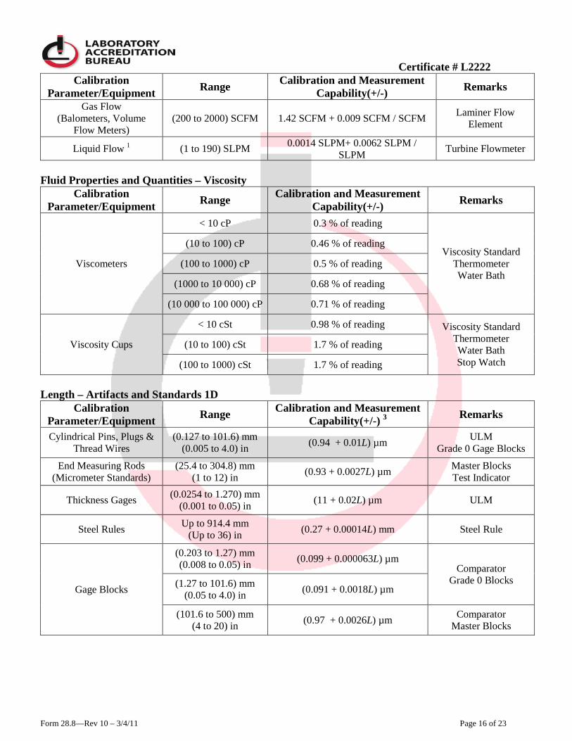
Fluid Properties and Quantities – Flow
Calibration Parameter/Equipment Range Calibration and Measurement
Capability(+/-) Remarks
Air Speed Velocity (Anemometers, Pitot
Tubes) (1.5 to 30) m/s (0.009 m/s + 0.011 m/s / m/s) Pitot Tube
Manometer
Gas Flow 1
(Mass & Volume Flow Meters)
(30 to 400) SLPM 0.2 SLPM + 0.0027 SLPM / SLPM Bell Prover
(0.1 to 35) SLPM 0.002 SLPM + 0.0013 SLPM / SLPM
Piston Prover (0 to 100) SCCM 0.42 SCCM + 0.0098 SCCM / SCCM
Certificate # L2222
Form 28.8—Rev 10 – 3/4/11 Page 16 of 23
Calibration Parameter/Equipment Range Calibration and Measurement
Capability(+/-) Remarks
Gas Flow
(Balometers, Volume Flow Meters)
(200 to 2000) SCFM 1.42 SCFM + 0.009 SCFM / SCFM Laminer Flow Element
Liquid Flow 1 (1 to 190) SLPM 0.0014 SLPM+ 0.0062 SLPM / SLPM Turbine Flowmeter
Fluid Properties and Quantities – Viscosity
Calibration Parameter/Equipment Range Calibration and Measurement
Capability(+/-) Remarks
Viscometers
< 10 cP 0.3 % of reading
Viscosity Standard Thermometer Water Bath
(10 to 100) cP 0.46 % of reading
(100 to 1000) cP 0.5 % of reading
(1000 to 10 000) cP 0.68 % of reading
(10 000 to 100 000) cP 0.71 % of reading
Viscosity Cups
< 10 cSt 0.98 % of reading Viscosity Standard Thermometer Water Bath Stop Watch
(10 to 100) cSt 1.7 % of reading
(100 to 1000) cSt 1.7 % of reading
Length – Artifacts and Standards 1D
Calibration Parameter/Equipment Range Calibration and Measurement
Capability(+/-) 3 Remarks
Cylindrical Pins, Plugs & Thread Wires
(0.127 to 101.6) mm (0.005 to 4.0) in (0.94 + 0.01L) µm ULM
Grade 0 Gage Blocks
End Measuring Rods (Micrometer Standards)
(25.4 to 304.8) mm (1 to 12) in (0.93 + 0.0027L) µm Master Blocks
Test Indicator
Thickness Gages (0.0254 to 1.270) mm (0.001 to 0.05) in (11 + 0.02L) µm ULM
Steel Rules Up to 914.4 mm (Up to 36) in (0.27 + 0.00014L) mm Steel Rule
Gage Blocks
(0.203 to 1.27) mm (0.008 to 0.05) in (0.099 + 0.000063L) µm
Comparator Grade 0 Blocks (1.27 to 101.6) mm
(0.05 to 4.0) in (0.091 + 0.0018L) µm
(101.6 to 500) mm (4 to 20) in (0.97 + 0.0026L) µm Comparator
Master Blocks
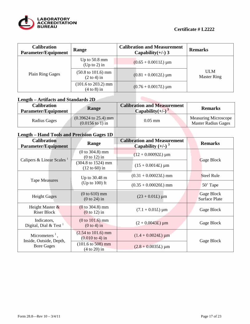
Certificate # L2222
Form 28.8—Rev 10 – 3/4/11 Page 17 of 23
Calibration Parameter/Equipment Range Calibration and Measurement
Capability(+/-) 3 Remarks
Plain Ring Gages
Up to 50.8 mm (Up to 2) in (0.65 + 0.0011L) µm
ULM Master Ring
(50.8 to 101.6) mm (2 to 4) in (0.81 + 0.0012L) µm
(101.6 to 203.2) mm (4 to 8) in (0.76 + 0.0017L) µm
Length – Artifacts and Standards 2D
Calibration Parameter/Equipment Range Calibration and Measurement
Capability(+/-) 3 Remarks
Radius Gages (0.39624 to 25.4) mm (0.0156 to 1) in 0.05 mm Measuring Microscope
Master Radius Gages Length – Hand Tools and Precision Gages 1D
Calibration Parameter/Equipment Range Calibration and Measurement
Capability (+/-) 3 Remarks
Calipers & Linear Scales 1
(0 to 304.8) mm (0 to 12) in (12 + 0.00092L) µm
Gage Block (304.8 to 1524) mm (12 to 60) in (15 + 0.0014L) µm
Tape Measures Up to 30.48 m (Up to 100) ft
(0.31 + 0.00023L) mm Steel Rule
(0.35 + 0.00020L) mm 50’ Tape
Height Gages (0 to 610) mm (0 to 24) in (23 + 0.01L) µm Gage Block
Surface Plate
Height Master & Riser Block
(0 to 304.8) mm (0 to 12) in (7.1 + 0.01L) µm Gage Block
Indicators, Digital, Dial & Test 1
(0 to 101.6) mm (0 to 4) in (2 + 0.0043L) µm Gage Block
Micrometers 1 , Inside, Outside, Depth,
Bore Gages
(2.54 to 101.6) mm (0.010 to 4) in (1.4 + 0.0024L) µm
Gage Block (101.6 to 508) mm
(4 to 20) in (2.8 + 0.0035L) µm
Certificate # L2222
Form 28.8—Rev 10 – 3/4/11 Page 18 of 23
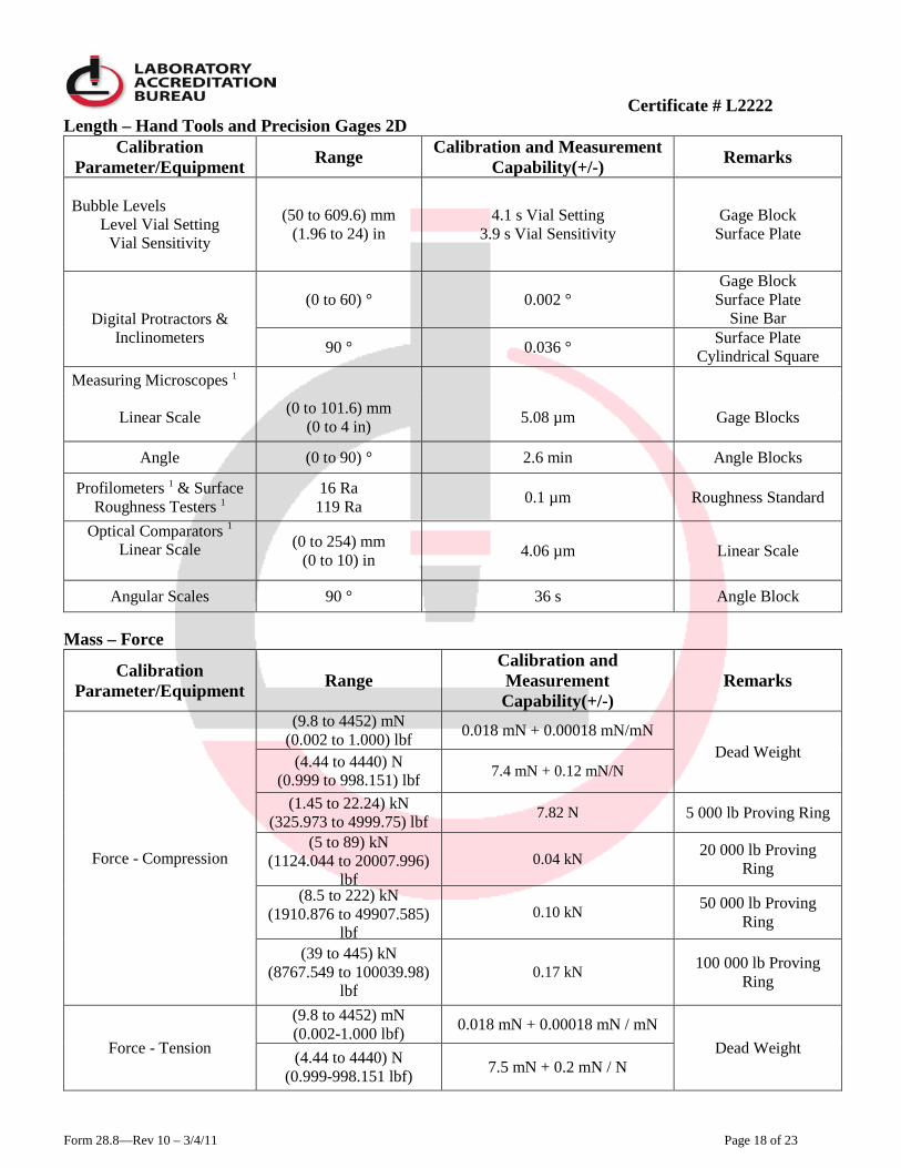
Length – Hand Tools and Precision Gages 2D Calibration
Parameter/Equipment Range Calibration and Measurement Capability(+/-) Remarks
Bubble Levels Level Vial Setting
Vial Sensitivity
(50 to 609.6) mm (1.96 to 24) in
4.1 s Vial Setting 3.9 s Vial Sensitivity
Gage Block Surface Plate
Digital Protractors &
Inclinometers
(0 to 60) ° 0.002 ° Gage Block
Surface Plate Sine Bar
90 ° 0.036 ° Surface Plate Cylindrical Square
Measuring Microscopes 1
Linear Scale (0 to 101.6) mm (0 to 4 in) 5.08 µm Gage Blocks
Angle (0 to 90) ° 2.6 min Angle Blocks
Profilometers 1 & Surface Roughness Testers 1
16 Ra 119 Ra 0.1 µm Roughness Standard
Optical Comparators 1
Linear Scale
(0 to 254) mm (0 to 10) in 4.06 µm Linear Scale
Angular Scales 90 ° 36 s Angle Block Mass – Force
Calibration Parameter/Equipment Range
Calibration and Measurement Capability(+/-)
Remarks
Force - Compression
(9.8 to 4452) mN (0.002 to 1.000) lbf 0.018 mN + 0.00018 mN/mN
Dead Weight (4.44 to 4440) N (0.999 to 998.151) lbf 7.4 mN + 0.12 mN/N
(1.45 to 22.24) kN (325.973 to 4999.75) lbf 7.82 N 5 000 lb Proving Ring
(5 to 89) kN (1124.044 to 20007.996)
lbf 0.04 kN 20 000 lb Proving
Ring
(8.5 to 222) kN (1910.876 to 49907.585)
lbf 0.10 kN 50 000 lb Proving
Ring
(39 to 445) kN (8767.549 to 100039.98)
lbf 0.17 kN 100 000 lb Proving
Ring
Force - Tension
(9.8 to 4452) mN (0.002-1.000 lbf) 0.018 mN + 0.00018 mN / mN
Dead Weight (4.44 to 4440) N (0.999-998.151 lbf) 7.5 mN + 0.2 mN / N
Certificate # L2222
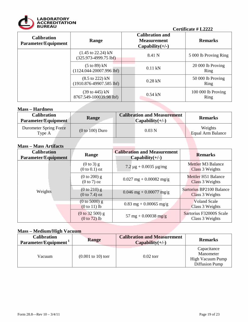
Form 28.8—Rev 10 – 3/4/11 Page 19 of 23
Calibration Parameter/Equipment Range
Calibration and Measurement Capability(+/-)
Remarks
(1.45 to 22.24) kN (325.973-4999.75 lbf) 8.41 N 5 000 lb Proving Ring
(5 to 89) kN (1124.044-20007.996 lbf) 0.11 kN 20 000 lb Proving
Ring
(8.5 to 222) kN (1910.876-49907.585 lbf) 0.28 kN 50 000 lb Proving
Ring
(39 to 445) kN 8767.549-100039.98 lbf) 0.54 kN 100 000 lb Proving
Ring Mass – Hardness
Calibration Parameter/Equipment Range Calibration and Measurement
Capability(+/-) Remarks
Durometer Spring Force Type A (0 to 100) Duro 0.03 N Weights
Equal Arm Balance
Mass – Mass Artifacts
Calibration Parameter/Equipment Range Calibration and Measurement
Capability(+/-) Remarks
Weights
(0 to 3) g (0 to 0.1) oz 7.2 µg + 0.0035 µg/mg Mettler M3 Balance
Class 3 Weights
(0 to 200) g (0 to 7) oz 0.027 mg + 0.00082 mg/g Mettler H51 Balance
Class 3 Weights
(0 to 210) g (0 to 7.4) oz 0.046 mg + 0.00077 mg/g Sartorius BP2100 Balance
Class 3 Weights (0 to 5000) g (0 to 11) lb 0.83 mg + 0.00065 mg/g Voland Scale
Class 3 Weights (0 to 32 500) g
(0 to 72) lb 57 mg + 0.00038 mg/g Sartorius F32000S Scale Class 3 Weights
Mass – Medium/High Vacuum
Calibration Parameter/Equipment 1 Range Calibration and Measurement
Capability(+/-) Remarks
Vacuum (0.001 to 10) torr 0.02 torr
Capacitance Manometer
High Vacuum Pump Diffusion Pump
Certificate # L2222
Form 28.8—Rev 10 – 3/4/11 Page 20 of 23
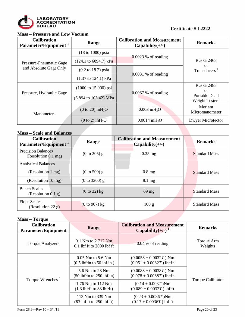
Mass – Pressure and Low Vacuum Calibration
Parameter/Equipment 1 Range Calibration and Measurement Capability(+/-) Remarks
Pressure-Pneumatic Gage
and Absolute Gage Only
(18 to 1000) psia 0.0023 % of reading
Ruska 2465 or
Transducers 1
(124.1 to 6894.7) kPa
(0.2 to 18.2) psia 0.0031 % of reading
(1.37 to 124.1) kPa
Pressure, Hydraulic Gage (1000 to 15 000) psi
0.0067 % of reading
Ruska 2485 or
Portable Dead Weight Tester 1 (6.894 to 103.42) MPa
Manometers (0 to 20) inH2O 0.003 inH2O Meriam
Micromanometer
(0 to 2) inH2O 0.0014 inH2O Dwyer Microtector
Mass – Scale and Balances
Calibration Parameter/Equipment 1 Range Calibration and Measurement
Capability(+/-) Remarks
Precision Balances (Resolution 0.1 mg) (0 to 205) g 0.35 mg Standard Mass
Analytical Balances
Standard Mass (Resolution 1 mg) (0 to 500) g 0.8 mg
(Resolution 10 mg) (0 to 3200) g 8.1 mg
Bench Scales (Resolution 0.1 g) (0 to 32) kg 69 mg Standard Mass
Floor Scales (Resolution 22 g) (0 to 907) kg 100 g Standard Mass
Mass – Torque
Calibration Parameter/Equipment Range Calibration and Measurement
Capability(+/-) 4 Remarks
Torque Analyzers 0.1 Nm to 2 712 Nm 0.1 lbf·ft to 2000 lbf·ft 0.04 % of reading Torque Arm
Weights
Torque Wrenches 1
0.05 Nm to 5.6 Nm (0.5 lbf·in to 50 lbf·in )
(0.0058 + 0.0032T ) Nm (0.051 + 0.0032T ) lbf·in
Torque Calibrator
5.6 Nm to 28 Nm (50 lbf·in to 250 lbf·in)
(0.0088 + 0.0038T ) Nm (0.078 + 0.0038T ) lbf·in
1.76 Nm to 112 Nm (1.3 lbf·ft to 83 lbf·ft)
(0.14 + 0.003T )Nm (0.089 + 0.0032T ) lbf·ft
113 Nm to 339 Nm (83 lbf·ft to 250 lbf·ft)
(0.23 + 0.0036T )Nm (0.17 + 0.0036T ) lbf·ft
Certificate # L2222
Form 28.8—Rev 10 – 3/4/11 Page 21 of 23
Calibration Parameter/Equipment Range Calibration and Measurement
Capability(+/-) 4 Remarks
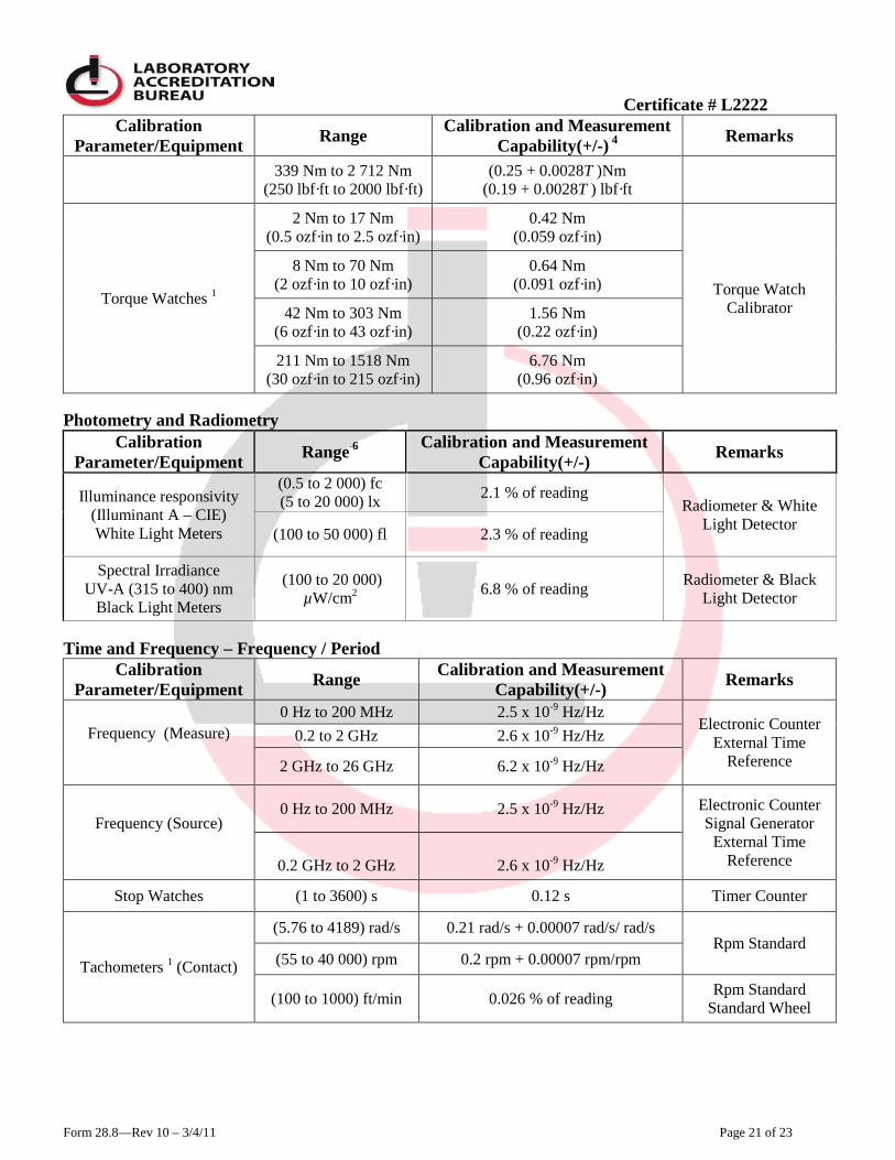
339 Nm to 2 712 Nm (250 lbf·ft to 2000 lbf·ft)
(0.25 + 0.0028T )Nm (0.19 + 0.0028T ) lbf·ft
Torque Watches 1
2 Nm to 17 Nm (0.5 ozf·in to 2.5 ozf·in)
0.42 Nm (0.059 ozf·in)
Torque Watch Calibrator
8 Nm to 70 Nm (2 ozf·in to 10 ozf·in)
0.64 Nm (0.091 ozf·in)
42 Nm to 303 Nm (6 ozf·in to 43 ozf·in)
1.56 Nm (0.22 ozf·in)
211 Nm to 1518 Nm (30 ozf·in to 215 ozf·in)
6.76 Nm (0.96 ozf·in)
Photometry and Radiometry
Calibration Parameter/Equipment Range 6 Calibration and Measurement
Capability(+/-) Remarks
Illuminance responsivity (Illuminant A – CIE) White Light Meters
(0.5 to 2 000) fc (5 to 20 000) lx 2.1 % of reading
Radiometer & White Light Detector (100 to 50 000) fl 2.3 % of reading
Spectral Irradiance UV-A (315 to 400) nm
Black Light Meters
(100 to 20 000) µW/cm2 6.8 % of reading Radiometer & Black
Light Detector
Time and Frequency – Frequency / Period
Calibration Parameter/Equipment Range Calibration and Measurement
Capability(+/-) Remarks
Frequency (Measure)
0 Hz to 200 MHz 2.5 x 10⁻⁹ Hz/Hz Electronic Counter
External Time Reference
0.2 to 2 GHz 2.6 x 10⁻⁹ Hz/Hz
2 GHz to 26 GHz 6.2 x 10⁻⁹ Hz/Hz
Frequency (Source)
0 Hz to 200 MHz 2.5 x 10⁻⁹ Hz/Hz Electronic Counter Signal Generator
External Time Reference
0.2 GHz to 2 GHz
2.6 x 10⁻⁹ Hz/Hz
Stop Watches (1 to 3600) s 0.12 s Timer Counter
Tachometers 1 (Contact)
(5.76 to 4189) rad/s 0.21 rad/s + 0.00007 rad/s/ rad/s Rpm Standard
(55 to 40 000) rpm 0.2 rpm + 0.00007 rpm/rpm
(100 to 1000) ft/min 0.026 % of reading Rpm Standard Standard Wheel
Certificate # L2222
Form 28.8—Rev 10 – 3/4/11 Page 22 of 23
Calibration Parameter/Equipment Range Calibration and Measurement
Capability(+/-) Remarks
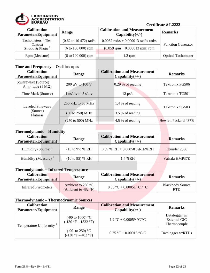
Tachometers 1 (Non-Contact)
Strobo & Photo 1
(0.62 to 10 472) rad/s 0.0062 rad/s + 0.000013 rad/s/ rad/s Function Generator
(6 to 100 000) rpm (0.059 rpm + 0.000013 rpm) rpm
Rpm (Measure) (6 to 100 000) rpm 1.2 rpm Optical Tachometer
Time and Frequency – Oscilloscopes
Calibration Parameter/Equipment Range Calibration and Measurement
Capability(+/-) Remarks
Squarewave (Source) Amplitude (1 MΩ) 200 µV to 100 V 0.29 % of reading Tektronix PG506
Time Mark (Source) 1 ns/div to 5 s/div 12 µs/s Tektronix TG501
Leveled Sinewave (Source) Flatness
250 kHz to 50 MHz 1.4 % of reading Tektronix SG503
(50 to 250) MHz 3.5 % of reading
(250 to 500) MHz 4.5 % of reading Hewlett Packard 437B
Thermodynamic – Humidity
Calibration Parameter/Equipment Range Calibration and Measurement
Capability(+/-) Remarks
Humidity (Source) 1 (10 to 95) % RH 0.59 % RH + 0.00058 %RH/%RH Thunder 2500
Humidity (Measure) 1 (10 to 95) % RH 1.4 %RH Vaisala HMP37E
Thermodynamic – Infrared Temperature
Calibration Parameter/Equipment Range Calibration and Measurement
Capability(+/-) Remarks
Infrared Pyrometers Ambient to 250 °C (Ambient to 482 °F) 0.33 °C + 0.00051 °C / °C Blackbody Source
RTD Thermodynamic – Thermodynamic Sources
Calibration Parameter/Equipment Range Calibration and Measurement
Capability(+/-) Remarks
Temperature Uniformity 1
(-90 to 1000) °C (-130 °F – 1832 °F) 1.2 °C + 0.00059 °C/°C
Datalogger w/ External CJC Thermocouple
(-90 to 250) °C (-130 °F – 482 °F) 0.25 °C + 0.00015 °C/C Datalogger w/RTDs
Certificate # L2222
Form 28.8—Rev 10 – 3/4/11 Page 23 of 23
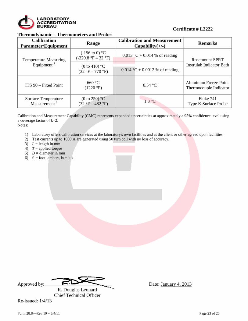
Thermodynamic – Thermometers and Probes Calibration
Parameter/Equipment Range Calibration and Measurement Capability(+/-) Remarks
Temperature Measuring Equipment 1
(-196 to 0) °C (-320.8 °F – 32 °F) 0.013 °C + 0.014 % of reading
Rosemount SPRT Instrulab Indicator Bath (0 to 410) °C
(32 °F – 770 °F)
0.014 °C + 0.0012 % of reading
ITS 90 – Fixed Point 660 °C (1220 °F) 0.54 °C Aluminum Freeze Point
Thermocouple Indicator
Surface Temperature Measurement 1
(0 to 250) °C (32 °F – 482 °F) 1.3 °C Fluke 741
Type K Surface Probe Calibration and Measurement Capability (CMC) represents expanded uncertainties at approximately a 95% confidence level using a coverage factor of k=2. Notes:
1) Laboratory offers calibration services at the laboratory's own facilities and at the client or other agreed upon facilities. 2) Test currents up to 1000 A are generated using 50 turn coil with no loss of accuracy. 3) L = length in mm 4) T = applied torque 5) D = diameter in mm 6) fl = foot lambert, lx = lux
Approved by: Date: January 4, 2013
Chief Technical Officer R. Douglas Leonard
Re-issued: 1/4/13