century star milling cnc system
TRANSCRIPT

©2007 Wuhan Huazhong Numerical Control Co., Ltd
CenturyCenturyCenturyCentury StarStarStarStarMillingMillingMillingMilling CNCCNCCNCCNC SystemSystemSystemSystem
OperationOperationOperationOperation ManualManualManualManual
VVVV3.33.33.33.3DecemberDecemberDecemberDecember,,,, 2007200720072007
WuhanWuhanWuhanWuhan HuazhongHuazhongHuazhongHuazhong NumericalNumericalNumericalNumerical ControlControlControlControl Co.,Co.,Co.,Co., LtdLtdLtdLtd

Preface
i
PrefacePrefacePrefacePrefaceOrganizationOrganizationOrganizationOrganization ofofofof documentationdocumentationdocumentationdocumentation
1. Introduction
2. Setting up
3. Manual Operation
4. Automatic Operation
5. Program File Operation
6. Setting and Displaying
7. Network Services
8. Diagnosis
9. PLC Function
10. Parameters
ApplicabilityApplicabilityApplicabilityApplicability
This Operation Guide is applicable to the following CNC system:
HNC-21MD/22MD v05.62.07.10
InternetInternetInternetInternet AddressAddressAddressAddress
http://www.huazhongcnc.com/

Table of Contents
ii
TableTableTableTable ofofofof ContentsContentsContentsContentsPreface............................................................................................................................................. iSafety Precautions.......................................................................................................................... v1 Introduction............................................................................................................................ 1
1.1 Overall Layout............................................................................................................11.2 LCD Screen................................................................................................................ 21.3 Soft Keys.................................................................................................................... 4
1.3.1 Main Menu..................................................................................................... 41.3.2 PROG Submenu..............................................................................................51.3.3 RUN Submenu................................................................................................61.3.4 MDI Menu...................................................................................................... 71.3.5 TOOL Submenu..............................................................................................81.3.6 SET Submenu................................................................................................. 91.3.7 Diagnosis Submenu...................................................................................... 101.3.8 EXTEND MENU Submenu..........................................................................11
1.4 Manual Data Input Keyboard................................................................................... 131.5 Machine Control Keys..............................................................................................15
1.5.1 Mode Selection Switches..............................................................................151.5.2 Verify Key.....................................................................................................161.5.3 Multiple Step Keys....................................................................................... 161.5.4 Other Control Keys.......................................................................................171.5.5 Spindle and Auxiliary Operation Keys......................................................... 181.5.6 Speed Adjustment Keys................................................................................ 191.5.7 Axis Operation Keys.....................................................................................20
1.6 Other Control Keys...................................................................................................211.6.1 Emergency Stop............................................................................................211.6.2 Cycle Run..................................................................................................... 211.6.3 Feed Hold..................................................................................................... 21
1.7 Auxiliary Devices..................................................................................................... 221.7.1 Hand Pendant................................................................................................221.7.2 Data Exchange Port...................................................................................... 22
2 Setting Up.............................................................................................................................232.1 Power-on...................................................................................................................242.2 Reset/Emergency Stop..............................................................................................252.3 Homing (Reference-point Approach)....................................................................... 262.4 Hardware Limit and Software Limit.........................................................................282.5 Setting Tool Data...................................................................................................... 30
2.5.1 Tool Magazine.............................................................................................. 302.5.2 Tool Data Table.............................................................................................31
2.6 Coordinate System....................................................................................................323 Manual Operation................................................................................................................. 33
3.1 Jog Feed....................................................................................................................343.1.1 Requirements................................................................................................ 343.1.2 JOG Feedrate................................................................................................ 353.1.3 Adjusting JOG Feedrate............................................................................... 363.1.4 Rapid Traverse Feedrate............................................................................... 373.1.5 Adjusting Rapid Traverse Speed...................................................................38
3.2 Incremental Feed...................................................................................................... 393.2.1 Requirement..................................................................................................393.2.2 Incremental Feedrate.................................................................................... 40

Table of Contents
iii
3.2.3 Step Length...................................................................................................413.3 Manual Handwheel...................................................................................................42
3.3.1 Requirement..................................................................................................423.3.2 Axis Selection/Off Knob.............................................................................. 433.3.3 Magnification Selection Knob...................................................................... 433.3.4 Handwheel Rotation..................................................................................... 44
3.4 Spindle Operation..................................................................................................... 453.4.1 Requirements................................................................................................ 453.4.2 Spindle Control Keys....................................................................................463.4.3 Adjusting Spindle Speed...............................................................................47
3.5 Auxiliary Operation.................................................................................................. 483.5.1 Requirements................................................................................................ 483.5.2 Auxiliary Keys..............................................................................................48
4 Automatic Operation............................................................................................................ 494.1 Requirements............................................................................................................ 504.2 Program Loading...................................................................................................... 514.3 Program Verifying.................................................................................................... 534.4 Running Control....................................................................................................... 55
4.4.1 Cycle Run..................................................................................................... 574.4.2 Feed Hold..................................................................................................... 584.4.3 Pause Processing...........................................................................................594.4.4 Restart...........................................................................................................604.4.5 Pick Start Block............................................................................................ 614.4.6 B.P. Save.......................................................................................................634.4.7 B.P. LOAD....................................................................................................644.4.8 B.P. Recovery................................................................................................664.4.9 Align Tool..................................................................................................... 67
4.5 MDI Operation......................................................................................................... 685 Program File Operation........................................................................................................ 70
5.1 Opening a Program................................................................................................... 715.2 Creating a new Program File.................................................................................... 72
5.2.1 Program Format............................................................................................ 725.3 Editing a Program File..............................................................................................73
5.3.1 Editing an existing Program File.................................................................. 735.3.2 Editing a new Program File.......................................................................... 745.3.3 Keys for Editing............................................................................................755.3.4 Deleting a Block........................................................................................... 755.3.5 Making a Blocks Group................................................................................765.3.6 Deleting a Blocks Group...............................................................................765.3.7 Cutting a Blocks Group................................................................................ 775.3.8 Copying a Blocks Group.............................................................................. 775.3.9 Pasting a Blocks Group................................................................................ 785.3.10 Finding a String............................................................................................ 795.3.11 Replacing a String.........................................................................................805.3.12 Background Editing (Optional).................................................................... 80
5.4 Saving a Program File.............................................................................................. 815.5 Deleting an existing Program File............................................................................ 825.6 Changing a Program File Name............................................................................... 83
6 Setting and Displaying..........................................................................................................846.1 Setting Coordinates...................................................................................................856.2 Workpiece Size......................................................................................................... 86

Table of Contents
iv
6.3 Position and Coordinate Choice............................................................................... 876.4 System Time............................................................................................................. 886.5 View Switch..............................................................................................................89
7 Network Services (Optional)................................................................................................ 917.1 Ethernet Connection................................................................................................. 917.2 Network Connection.................................................................................................927.3 RS232 Connection.................................................................................................... 95
7.3.1 Setting the Parameters.................................................................................. 957.3.2 Setting Up the Connection............................................................................96
7.4 Sending Serial Procedures........................................................................................ 977.5 Receiving Serial Procedures..................................................................................... 98
8 Diagnosis.............................................................................................................................. 999 PLC Function......................................................................................................................100
9.1 F3: I/O Status..........................................................................................................1019.2 F4: Watch................................................................................................................102
10 Parameters.................................................................................................................. 10410.1 F1: Parameter Index................................................................................................105
10.1.1 Machine Parameters....................................................................................10610.1.2 Axis Parameters.......................................................................................... 10710.1.3 Servo Parameters........................................................................................ 10910.1.4 Compensation Parameters...........................................................................11010.1.5 PMC User Parameters.................................................................................111
10.2 F2: Password Change..............................................................................................11210.3 F3: Password Input................................................................................................. 11310.4 F5: Load Default.....................................................................................................11310.5 F6: Back to Last......................................................................................................11310.6 F7: Backup..............................................................................................................11410.7 F8: Load..................................................................................................................115

Safety Precautions
v
SafetySafetySafetySafety PrecautionsPrecautionsPrecautionsPrecautionsThis section enumerates the safety precautions for protecting the user and preventing
damage to the machine. Read the contents of this part thoroughly before attempting to use
the machine.
1.1.1.1. OperationOperationOperationOperation ManualManualManualManual
While this operation manual supplied with an numerical control unit provides an overall
description of the machine’s functions, some functions are specific for that machine alone
and may not be available for another model. Check the specification of the machine if in
doubt as to its machine-specific functions.
2.2.2.2. WorkingWorkingWorkingWorking EnvironmentEnvironmentEnvironmentEnvironment
� Working temperature: 0°C - 45°C (32°F to 113°F), no freezing
� Temperature variation: less than 1.1°C/min (2°F/min)
� Humidity: below 90% Relative Humidity, non-condensing and without frost
Less than 75% Relative Humidity is more desirable.
95% Relative Humidity is for the shot-term use (within one month)
� Storage: –20°C to 60°C (-4°F to 140°F), non-condensing and without frost.
� Environment: All devices should be placed indoors and away from sunshine, dust,
eroding gases and moisture.
� Height: 1000 meter above the sea level (2000meter)
� Vibration: Impact during transportation or other situations should be less than 5.9m/s
(0.6g) for vibrations in the range between 10 to 60Hz.
3.3.3.3. GroundingGroundingGroundingGrounding
Correct grounding is critical for the numerical control unit and other electrical devices.
� No grounding or incorrect grounding may injure the operator or damage components
of the numerical control devices.
� If the devices are not correctly grounded, inductive interference from electric motors
and appliances can lead to errors and unexpected results.

Safety Precautions
vi
4.4.4.4. PowerPowerPowerPower
Electronic control tank is to supply the power for the milling machine. Please refer to
the machine installation instruction manual.
5.5.5.5. FilterFilterFilterFilter
Filters are used on cooling fans to prevent dust from entering into devices. However, it
would prevent adequate cooling if the filters become clogged. It is recommended that
the user clean the filters every three months. In dusty environments such as wood
routers, clean the filters more often.
6.6.6.6. Non-OperationNon-OperationNon-OperationNon-Operation
After a long period of non-operation, numerical control devices should be cleaned and
dried. Also check the wiring and ground connections. Once power is resumed after
non-operation, observe the operation for several hours to make sure there is no
unexpected behavior.
7.7.7.7. ManualManualManualManual DataDataDataData InputInputInputInput (MDI)(MDI)(MDI)(MDI) panelpanelpanelpanel
After turning on the power immediately, do not touch any of the keys on the Manual
Data Input (MDI) panel until the position display or alarm screen appears on the
numerical control unit. Since some of the keys on the MDI panel are dedicated to the
maintenance or other special operations, pressing any of these keys may prevent the
numerical control unit from entering its normal state. Starting the machine in the wrong
state may cause unexpected motion or behavior.
8.8.8.8. CheckCheckCheckCheck
Before operating the machine, thoroughly check the entered data, including parameters,
program and settings. Operating the machine with incorrectly specified data may also result
in unexpected motion or behavior that can damage the workpiece, damage the machine, or
injure the operator.

Safety Precautions
vii
9.9.9.9. TrialTrialTrialTrial RunRunRunRun
Never machine a workpiece without checking the machine's status at first. Before using
the machine for a production run, make sure that the machine operates correctly by
doing a trial run including, for example, a single block with a feedrate override or a
machine lock function. Another possibility is to do the trial run without a tool or
workpiece mounted. Failure to confirm the correct operation with a trial run may result
in unexpected motion or behavior that can damage the workpiece, damage the machine,
or injure the operator.
10.10.10.10. FeedrateFeedrateFeedrateFeedrate
Ensure that the specified feedrate is appropriate for the intended operation. The
appropriate feedrate varies with the operation. Generally each machine has a maximum
allowable feedrate found in the machine's operation manual. If a machine is run at other
than the correct feedrate or if the maximum allowable feedrate is exceeded, unexpected
motion or behavior may result that can damage the workpiece, damage the machine, or
injure the operator.
11.11.11.11. ToolToolToolTool compensationcompensationcompensationcompensation functionfunctionfunctionfunction
When using the tool compensation function, thoroughly check the direction and amount
of compensation for each tool. Operating the machine with incorrectly specified data
may produce unexpected motion or behavior that can damage the workpiece, damage
the machine, or injure the operator.
12.12.12.12. ParametersParametersParametersParameters
Usually, there is no need to change the factory-set parameters of the NC unit and PMC.
However, when there is no choice other than to change a parameter, be sure you fully
understand the function of the parameter before making any change. Failure to set a
parameter correctly may produce unexpected motion or behavior that can damage the
workpiece, damage the machine, or injure the operator.

1. Introduction
1
1111 IntroductionIntroductionIntroductionIntroduction
1.11.11.11.1 OverallOverallOverallOverall LayoutLayoutLayoutLayoutThe user operates the milling either through the Machine Control Panel (Figure 1.1) or a
Hand Pendant (optional) (Figure 1.2). A Data Exchange Port (optional) (Figure 1.3) allows
the user to exchange data between the NCU and other computers through an Ethernet
connection, RS232 or floppy disk. A PS/2 connector in the Data Exchange Port let the user
plug in a keyboard.
MDIkeyboard
LCDScreen
Soft keys
Machinecontrolkeys
Figure 1.1 Machine Control Panel
Figure 1.2 Hand Pendant Figure 1.3 Data Exchange Port

1. Introduction
2
As it is shown in Figure 1.1, there four main areas on the Machine Control Panel: LCD
Screen, Soft keys, Manual Data Input (MDI) keyboard and Machine Control keys. These are
shown in detail below.
1.21.21.21.2 LCDLCDLCDLCD ScreenScreenScreenScreenThe LCD screen displays the machine’s status, the tool’s position, the program’s content andother information.
Figure 1.4 LCD screen on the MCP
1) Machine information
� Mode: automatic, single block, manual, incremental, reference, emergency stop.
� Current status: running or error.
� System time: current system time.
2) Current block information
It shows the current block in the program.
5
6
7
8
9
4
3
1
2

1. Introduction
3
3) View
Different views can be selected: graphical figure, numerical figure, overall positions,
and G code.
4) Diameter or Radius Programming, Metric/Inch, feedrate per minute, feedrate per
revolution, rapid traverse speed, feedrate override, spindle override.
5) Program Index
It shows the program name and the program block number
6) Position and Coordinate system
� Different position value can be shown: the command position, actual position,
distance to go, trace error, or compensation.
� Different coordinate systems can be selected: Machine coordinate system,
Workpiece coordinate system, and Relative coordinate system.
7) Origin Position
It shows the origin position of the workpiece in the machine coordinate system.
8) Auxiliary Information
It shows the M code, S code, and T code in the program.
9) Menu
It is corresponded to the soft keys on the machine control panel.

1. Introduction
4
1.31.31.31.3 SoftSoftSoftSoft KeysKeysKeysKeysBeneath the LCD screen are the “Soft keys” from F1 to F10. Their functions change
depending on which main menu or submenu is active.
Figure 1.5 Soft keys on the machine control panel
1.3.11.3.11.3.11.3.1 MMMMainainainain MenuMenuMenuMenu
The following figure shows the main soft key menu. The keys display the function of that
key in the abbreviated notation.
PROGF1
RUNF2
MDIF3
TOOLF4
SETF5
DIAGF6
DNCF7
VIEWF9
MOREF10
Figure 1.6 Main Menu
PROG is the key that selects the programming function.
RUN selects the submenu which let the operator control the program running interactively.
MDI stands for Manual Data Input; it let the operator manually write G-code programs and
input data.
TOOL selects the tool submenu to let the operator choose tool offsets and parameters.
SET picks the setting submenu letting the operator set axis and machine parameters.
DIAG selects the diagnosis submenu to alter alarms and machining statistics.
DNC stands for Direct Numerical Control, letting a program load from another computer.
VIEW selects one of several ways to view the screen display.
MORE picks an extended menu with more commands.

1. Introduction
5
1.3.21.3.21.3.21.3.2 PROGPROGPROGPROG SubmenuSubmenuSubmenuSubmenu
PROG.F1
OPEN
F1
EDIT
F2
NEW
F3
SAVE
F4
VER
F5
PAUSE
F6
RE-START
F7
VIEW-->>F9
BACK
F10
Figure 1.7 PROG Submenu
OPEN picks which program is to be run or edited.
EDIT allows the opened program to be edited.
NEW creates a new program while SAVE stores an edited program in memory.
VER verifies whether the opened program has correct syntax and tool path.
PAUSE temporarily halts a running program immediately.
RESTART resumes program running.
VIEW selects one of several ways to view the screen display.
BACK goes back to the main menu.

1. Introduction
6
1.3.31.3.31.3.31.3.3 RUNRUNRUNRUN SubmenuSubmenuSubmenuSubmenu
RUNCTRL.
F2
PICKBLOCK
F1
BPSAVE
F5
BPLOAD
F6
VIEW-->>F9
BACK
F10
From the red line F1
From the specified line F2
From the current line F3
Figure 1.8 RUN Submenu
PICK BLOCK picks a block of the selected program and let the program run from this
block.
BP stands for break point, is used for operator to suspend and resume the machining
process.
BP SAVE allows the operator to save information at the current break point to memory.
B.P LOAD is to load the information at the saved breakpoint so that the program can be
executed at the break point.
VIEW selects one of several ways to view the screen display.
BACK goes back to the main menu.

1. Introduction
7
1.3.41.3.41.3.41.3.4 MDIMDIMDIMDIMenuMenuMenuMenu
The MDI submenu has five soft keys.
MDIF3
MDISTOP
F1
MDICLEAR
F2
GOTOB.P.F7
ALIGNTOOL
F9
BACK
F10
Figure 1.9 MDI menu
MDI STOP stops the executing of the MDI command.
MDI CLEAR clears all the dimensional data manually input.
GOTO BP let the tool go back to the breakpoint after an interactive intervention during
automatic machining.
ALIGN TOOL allows operator to re-align the tool’s dimension.
BACK goes back to the main menu.

1. Introduction
8
1.3.51.3.51.3.51.3.5 TOOLTOOLTOOLTOOLSubmenuSubmenuSubmenuSubmenu
TOOLDataF4
Magazine
F1
DATA
F2
VIEW-->>F9
BACKTOMAIN
F10
Figure 1.10 TOOL Submenu
Magazine allows the user to group the tools to magazine.
DATA let the operator type the tool’s parameter such as length, radius, life expectancy and
group number.
VIEW selects one of several ways to view the screen display.
BACK goes back to the main menu.

1. Introduction
9
1.3.61.3.61.3.61.3.6 SETSETSETSET SubmenuSubmenuSubmenuSubmenu
The SET submenu has six soft keys.
SETTF5
W.C.S.
F1
DISP.PARA
F2
VIEW-->>F9
BACKTOMAIN
F10
POS.TYPE
F3
DNCPARA.
F6
G54
F1
CURR.W.C.S.
F7
REL.ORIGIN
F8
BACKTOMAIN
F10
G55
F2
G56
F3
G57
F4
G58
F5
G59
F6
Position
Command
Actual
Dist. to Go
Trace Error
Compensation
Coordinates
M.C.S
W.C.S
R.C.S
Figure 1.11 SET Submenu
WCS, stands for Workpiece Coordinate System, is used for user to define the origin position
of workpiece coordinates.
PART SIZE let the operator provide the workpiece dimension for graphical.
POS TYPE is to select the position type to be displayed on the screen.
DNC PARA allows the user to change the communication parameters for RS232.
VIEW selects one of several ways to view the screen display.
BACK goes back to the main menu.

1. Introduction
10
1.3.71.3.71.3.71.3.7 DiagnosisDiagnosisDiagnosisDiagnosis SubmenuSubmenuSubmenuSubmenu
The DiagnosisDiagnosisDiagnosisDiagnosis orororor DIAGDIAGDIAGDIAG submenu has six soft keys.
DIAGF6
STAT
F2
INIT
F3
ALARM
F6
ALARMListF7
BACK
F10
VIEW-->>F9
Figure 1.12 Diagnosis Submenu
STAT, allows the user to check the statistics information.
INIT let the operator set initial value for statistics.
ALARM is used to display the causes of an alarm if it occurs.
ALARM LIST lists all the alarms happened before.
VIEW selects one of several ways to view the screen display.
BACK goes back to the main menu.

1. Introduction
11
1.3.81.3.81.3.81.3.8 EXTENDEXTENDEXTENDEXTENDMENUMENUMENUMENU SubmenuSubmenuSubmenuSubmenu
There four more soft keys under EXTEND MENU submenu.
PLC, stands for Programmable Logic Circuits, and allows the user to do PLC operations.
PARA is used to set/change parameters.
ABOUT let the user check the software’s version information.
REG, stands for register, let the operator register the software.
VIEW selects one of several ways to view the screen display.
BACK goes back to the main menu.

1. Introduction
12
EXTENDMENUF10
PLCF1
PARA.F3
ABOUTF4
REGI.F6
BACK,EDIT.
F8
VIEW-->>F9
BACKF10
LOAD
F1
Modify
F2
I/O
F3
Watch
F4
BACKUPF7
VIEW-->>F9
BACK
F10
PARAM.INDEX
F1
LOADDEFAULT
F5
BACKUPPREVAL
F6
LOADPARAM.
F8
BACKUPPARAM.
F7
PASSW.INPUT
F3
PASSW.CHANGE
F2
Back toMAINF10
X:[Mac->PMC] F1
Y:[PMC->Mac] F2
F:[CNC->PMC] F3
G:[PMC->CNC] F4
R:[REGIN PMC] F5
P:[Parameter] F6
B:[BLIFFER] F8
Cancel F9
Machine Parameters F1
Axis Parameters F2
Servo Parameters F3
Axis Compensation Parameters F4
PMC User Parameters F5
Trans-quadrant Compensation F6
System F1
Optional F2
Figure 1.13 MORE Submenu
1. Introduction
13
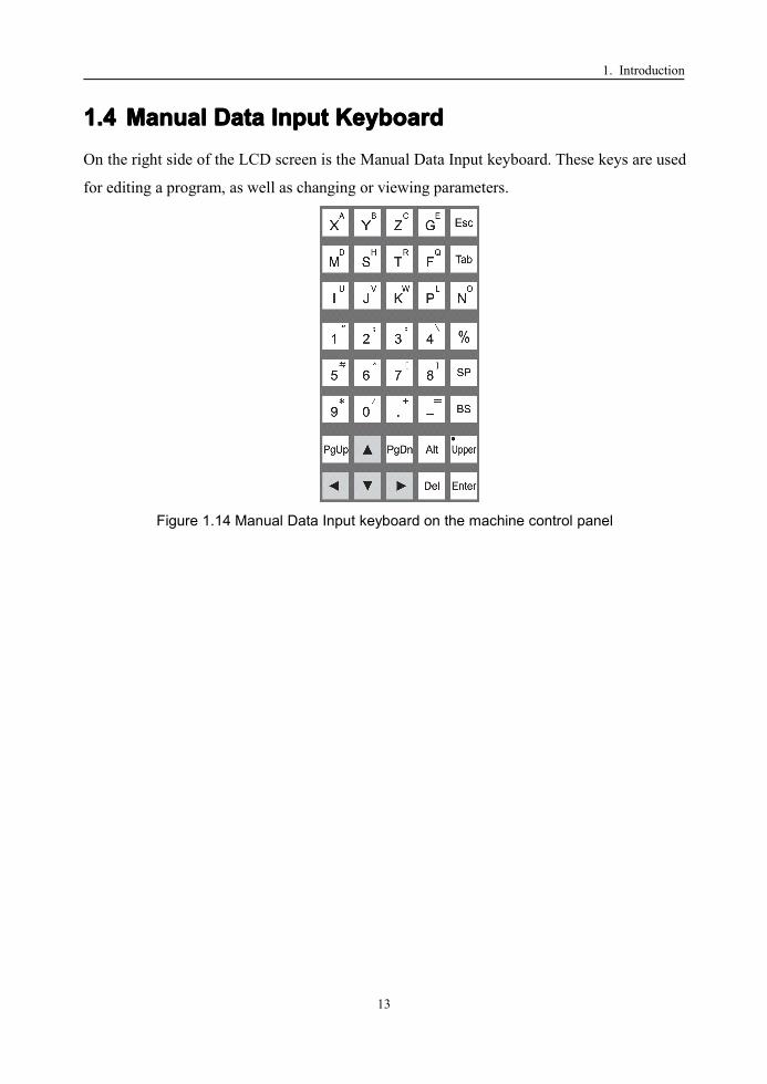
1.41.41.41.4 ManualManualManualManual DataDataDataData InputInputInputInput KeyboardKeyboardKeyboardKeyboardOn the right side of the LCD screen is the Manual Data Input keyboard. These keys are used
for editing a program, as well as changing or viewing parameters.
Figure 1.14 Manual Data Input keyboard on the machine control panel
1. Introduction
14
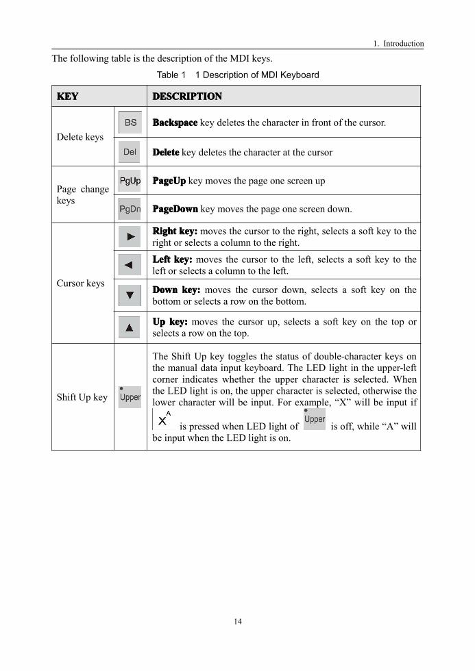
The following table is the description of the MDI keys.
Table 1 1 Description of MDI Keyboard
KEYKEYKEYKEY DESCRIPTIONDESCRIPTIONDESCRIPTIONDESCRIPTION
Delete keysBackspaceBackspaceBackspaceBackspace key deletes the character in front of the cursor.
DeleteDeleteDeleteDelete key deletes the character at the cursor
Page changekeys
PageUpPageUpPageUpPageUp key moves the page one screen up
PageDownPageDownPageDownPageDown key moves the page one screen down.
Cursor keys
RightRightRightRight key:key:key:key: moves the cursor to the right, selects a soft key to theright or selects a column to the right.
LeftLeftLeftLeft key:key:key:key: moves the cursor to the left, selects a soft key to theleft or selects a column to the left.
DownDownDownDown key:key:key:key: moves the cursor down, selects a soft key on thebottom or selects a row on the bottom.
UpUpUpUp key:key:key:key: moves the cursor up, selects a soft key on the top orselects a row on the top.
Shift Up key
The Shift Up key toggles the status of double-character keys onthe manual data input keyboard. The LED light in the upper-leftcorner indicates whether the upper character is selected. Whenthe LED light is on, the upper character is selected, otherwise thelower character will be input. For example, “X” will be input if
is pressed when LED light of is off, while “A” willbe input when the LED light is on.

1. Introduction
15
1.51.51.51.5 MachineMachineMachineMachine ControlControlControlControl KeysKeysKeysKeysAt the bottom of the machine control panel are the Machine Control keys. These keys operate
the machine directly.
Figure 1.15 Machine control keys on the machine control panel
1.5.11.5.11.5.11.5.1 ModeModeModeMode SelectionSelectionSelectionSelection SwitchesSwitchesSwitchesSwitches
The following figure shows the five switches that select the operation mode of the machine.
Note that the small LED “activation” light on the upper left of each key indicates in which mode
the machine is working.
Figure 1.16 Mode Selection Switches
The following table is the description of the mode selection keys.
Table 1 2 Description of Mode Selection Keys
KEYKEYKEYKEY DESCRIPTIONDESCRIPTIONDESCRIPTIONDESCRIPTION
AutomaticAutomaticAutomaticAutomatic (AUTO)(AUTO)(AUTO)(AUTO) modemodemodemode key:key:key:key: Pressing this key switches to Auto mode. InAUTO mode, workpiece can be machined automatically from a program.
SingleSingleSingleSingle BlockBlockBlockBlock (SBL)(SBL)(SBL)(SBL) modemodemodemode key:key:key:key: Pressing this key switches to “SBL” mode.In SBL mode, a program can be run block by block.
ManualManualManualManual (MAN)(MAN)(MAN)(MAN) modemodemodemode key:key:key:key: Pressing this key switches to manual operation or“jog” mode. In manual mode, any axis of the tool can be manually controlled.
IncrementalIncrementalIncrementalIncremental (INC)(INC)(INC)(INC) modemodemodemode key:key:key:key: Pressing this key switches to “INC” operationmode. In INC mode, the tool can be moved a number of steps along any axisby either the Axis keys or the hand wheel (Manual Pulse Generator). Thenumber of steps depends on which of the multiple-step keys is selected.
ReferenceReferenceReferenceReference (REF)(REF)(REF)(REF) modemodemodemode key:key:key:key: Pressing this key switches to “Reference” mode.In Reference mode, each motion axis can home exactly on its referenceposition.
Activationlight

1. Introduction
16
1.5.21.5.21.5.21.5.2 VerifyVerifyVerifyVerify KeyKeyKeyKey
Verify key shown in the following figure is used in conjunction with the Automatic Mode
key.
Figure 1.17 Verify Key
When the Verify key is activated, a program runs at a higher speed than normal machining.
The operator can run a program quickly, but the operator should be sure the program
performs the proper function.
1.5.31.5.31.5.31.5.3 MultipleMultipleMultipleMultiple StepStepStepStep KeysKeysKeysKeys
A step is equal to one micrometer (1 µm) for each linear axis (X, Y, Z) and 0.001 degrees for
each rotational axis. The following figure are the four multiple step selection keys used
during incremental operation. Again, the LED light on the key’s upper-left corner indicates
the selected multiple step. First the INC key is pushed to set the Incremental Mode, then the
desired number of multiple steps is pressed, and finally the desired Axis key is pressed.
Figure 1.18 Multiple Step Keys
The following table shows the description of multiple step keys.
Table 1 3 Description of Multiple Step Keys
KEYKEYKEYKEY DESCRIPTIONDESCRIPTIONDESCRIPTIONDESCRIPTION
Each key push moves that axis one step
Each key push moves that axis 10 steps
Each key push moves that axis 100 steps
Each key push moves that axis 1000 steps

1. Introduction
17
1.5.41.5.41.5.41.5.4 OtherOtherOtherOther ControlControlControlControl KeysKeysKeysKeys
The five keys below are other keys that control various machining functions.
Figure 1.19 Other Control Keys
The following table is the description of other control keys.
Table 1 4 Description of Other Control Keys
KEYKEYKEYKEY DESCRIPTIONDESCRIPTIONDESCRIPTIONDESCRIPTION
Over-travelOver-travelOver-travelOver-travel releasereleasereleaserelease key:key:key:key: When mechanical over-travel on any axisoccurs, press this key until the system is reset, then move the axis out ofover-travel.
Not used
BlockBlockBlockBlock BypassBypassBypassBypass key:key:key:key: Activating this key bypasses program blocks that startwith a “/” character.
ProgramProgramProgramProgram StopStopStopStop key:key:key:key: Activating this key enables the M01 G-code stopfunction, stopping the program at a desired block.
MachineMachineMachineMachine LockLockLockLock key:key:key:key: Activating this key prevents any motion from thespindle, the tool turret change or any axis; it is used for system testing.

1. Introduction
18
1.5.51.5.51.5.51.5.5 SpindleSpindleSpindleSpindle andandandandAuxiliaryAuxiliaryAuxiliaryAuxiliary OperationOperationOperationOperation KKKKeyseyseyseys
These nine keys are usually available in Manual mode. They control spindle, turret tool
selection, and coolant function. These functions are activated only when no program is
running.
Figure 1.20 Spindle and Auxiliary Operation Keys
Details of the keys are shown in the following table:
Table 1 5 Description of Spindle and Auxiliary Keys
KEYKEYKEYKEY DESCRIPTIONDESCRIPTIONDESCRIPTIONDESCRIPTION
CoolantCoolantCoolantCoolant SwitchSwitchSwitchSwitch key:key:key:key: This key opens or closes the coolant flow
ToolToolToolTool exchangeexchangeexchangeexchange enableenableenableenable key:key:key:key: Press this key to enable or disable toolexchange operation.
ToolToolToolTool lock/unlock:lock/unlock:lock/unlock:lock/unlock: After pressing this key, the tool will be release if it islocked before and will be locked if it is to be replaced in.
SpindleSpindleSpindleSpindle orientation:orientation:orientation:orientation: Pressing this key to let the spindle approach a certainposition that can align the spindle to its seat.
SpindleSpindleSpindleSpindle jogjogjogjog key:key:key:key: This key rotates the spindle for a short time after eachpress.
SpindleSpindleSpindleSpindle brake:brake:brake:brake: Pressing down this key will brake the spindle.
SpindleSpindleSpindleSpindle ClockwiseClockwiseClockwiseClockwise RotationRotationRotationRotation key:key:key:key: Pressing this key begins spindle rotationin the clockwise direction (top of workpiece moves toward operator).
SpindleSpindleSpindleSpindle StopStopStopStop key:key:key:key: Stop the spindle rotation by pressing this key.
SpindleSpindleSpindleSpindle Counter-clockwiseCounter-clockwiseCounter-clockwiseCounter-clockwise RotationRotationRotationRotation key:key:key:key: Pressing this key begins spindlerotation in the counter-clockwise direction (top of workpiece moves awayfrom operator).

1. Introduction
19
1.5.61.5.61.5.61.5.6 SpeedSpeedSpeedSpeedAdjustmentAdjustmentAdjustmentAdjustment KKKKeyseyseyseys
By pressing these keys, the spindle speed, rapid traverse speed and feed rate (machining
speed) can be adjusted. The first row controls the spindle speed, the second row controls the
rapid traverse speed and the bottom row controls feed rate.
Figure 1.21 Speed Adjustment Keys
These keys work by adjusting the speed relative to a “base” speed. Different modes
(Automatic, Single Block and Manual) may have different base speeds. The base speed is
set by the G-code program or the parameter.
For each row, pressing the center key sets the speed at 100% of the base speed; the LED
light in the key’s upper-left corner is lit to signify that the machine is running at 100 percent
of the base speed. Pressing the minus (-) key, decreases the base speed by a fixed percent;
pressing the plus (+) key, increases the base speed by a fixed percent. Below is an example
where the speeds are changed by 2%:
Table 1 6 Description of Speed Adjustment Keys
KEYKEYKEYKEY DESCRIPTIONDESCRIPTIONDESCRIPTIONDESCRIPTION
Pressing this key decreases the speed 2% for each press. The current speedor rate is displayed on the LCD screen.
Once this key is pressed, the override ratio is set to 100%. The LED lightindicates that the current speed is the base speed.
Pressing this key increases the speed 2% for each press. The current speedor rate is displayed on the LCD screen.

1. Introduction
20
1.5.71.5.71.5.71.5.7 AxisAxisAxisAxis OperationOperationOperationOperation KKKKeyseyseyseys
These nine keys are to select the desired axis and the direction of motion in various modes.
These keys only function in Manual Mode, INC Mode and Reference Mode. The LED light
in the upper-left corner specifies which axis or direction is selected.
Figure 1.22 Axis Operation Keys
Table 1 7 Description of Axis Operation Keys
KEYKEYKEYKEY DESCRIPTIONDESCRIPTIONDESCRIPTIONDESCRIPTION
In INC mode or Manual Mode, the tool moves the X axis in the positivedirection while +X is pressed, and in the negative direction while –X ispressed. In Reference mode, pressing the +X key homes the X axis (finds themachine reference on the X axis).
In INC mode or Manual Mode, the tool moves the Y axis in the positive directionwhile +Y is pressed, and in the negative direction while –Y is pressed. InReference mode, pressing the +Y key homes the Y axis (finds the machinereference on the Y axis).
In INC mode or Manual Mode, the tool moves the Z axis in the positivedirection while +Z is pressed, and in the negative direction while –Z ispressed. In Reference mode, pressing the +Z key homes the Z axis (findsmachine reference on the Z axis).
The 4TH axis is only valid for servo-driven spindle mills. In INC mode orManual Mode, the spindle moves in the positive direction while +4TH ispressed and in the negative direction while –4TH is pressed. In Referencemode, pressing the +4TH key homes the spindle (finds the spindle reference).
This key speeds up tool motion in Manual mode. It must be pressed inconjunction with one of the Axis keys.

1. Introduction
21
1.61.61.61.6 OtherOtherOtherOther ControlControlControlControl KeysKeysKeysKeys
1.6.11.6.11.6.11.6.1 EmergencyEmergencyEmergencyEmergency StopStopStopStop
An emergency stop button is on MCP to deal with abnormal situations. Pushing down the
button stops the machine from any further motion and sets the electronic to brake the motor
axes and spindle. Pulling upon this emergency button resets the software system and the
machine can operate again under computer or manual control.
Figure 1.23 Emergency Stop button
1.6.21.6.21.6.21.6.2 CycleCycleCycleCycle RunRunRunRun
A green “Cycle Run” button starts the automatic machining process.
Figure 1.24 Cycle Run button
1.6.31.6.31.6.31.6.3 FeedFeedFeedFeed HoldHoldHoldHold
A red “Feed Hold” button pauses machining under computer control.
Figure 1.25 Feed Hold button

1. Introduction
22
1.71.71.71.7 AuxiliaryAuxiliaryAuxiliaryAuxiliary DevicesDevicesDevicesDevices
1.7.11.7.11.7.11.7.1 HandHandHandHand PendantPendantPendantPendant
Usually a handwheel, an emergency stop button and override switches are assembled on a
Hand Pendant.
Manual Pulse Generator
Emergency Stop
Figure 1.26 Hand Pendant
1.7.21.7.21.7.21.7.2 DataDataDataData ExchangeExchangeExchangeExchange PortPortPortPort
Data exchange port is for inputting or outputting program data to the NC unit. LAN, RS232
are used for communication with other computer via cable. Floppy drive is for the floppy
disk. PC keyboard can be plugged in to operate the controller.
Floppy Drive
LANPC Keyboard
RS232
Figure 1.27 Data Exchange Port

2. Setting Up
23
2222 SettingSettingSettingSetting UpUpUpUpBefore machining a part, the operator needs to set up the machine coordinates and the
workpiece coordinates, define tools parameters and other machine preparations.
The general setup procedure includes six steps:
1) Power On
2) Reset
3) Reference home (point approach)
4) Define software limits
5) Set tool data
6) Set workpiece coordinates
The first three steps are always necessary once the machine is powered on. Step 4 is
necessary only when the machine is set up for the first time. Step 5 is done for each tool
cutter before it is used to cut the parts. Step 6 is done each time if a new program is used.
Let’s go through these steps in detail:

2. Setting Up
24
2.12.12.12.1 Power-onPower-onPower-onPower-onThe procedure to turn the power on:
1) Check and make sure the machine is safe to run.
2) Press down the Emergency Stop button on MCP.
3) Turn on the power of the machine (usually located in back of the machine and/or
beneath the control panel).
4) Make sure the fans run normally
5) Make sure the lamps on the machine control panel have been lighted on.

2. Setting Up
25
2.22.22.22.2 Reset/EmergencyReset/EmergencyReset/EmergencyReset/Emergency StopStopStopStopAfter Power-on, reset the control unit by twisting the Reset Button clockwise. Resetting the
servo and spindle power is to enable the machine. Pushing the RESET button down
generates an Emergency stop event and disables the servo and spindle.
Reset button
Turn clock-wise
Figure 2.1 Emergency Stop
Feed motion from the axis motors and the spindle motor will stop immediately when the
Emergency Stop (ES) button is pressed. This button can be used:
� when there is a machine malfunction
� before turning the power on or off
Once the ES button is pressed, the system enters into the “ES Mode”. In this mode, no
operation except reset is allowed. After curing the cause of the machine malfunction, or the
machine is turned on, the emergency stop button can be released by the RESET operation
(twisting the ES button clockwise).

2. Setting Up
26
2.32.32.32.3 HomingHomingHomingHoming (Reference-point(Reference-point(Reference-point(Reference-point Approach)Approach)Approach)Approach)In homing (sometimes called reference point approach), there is a reference point for each
axis. These reference points are used to set up the machine’s coordinate system. Since the
axis’ original positions are the same as the previous time, homing should always be
performed once the machine is turned on.
The following figure shows a diagram of a typical axis homing. The present location in red
is a distance from the Origin. When the axis homes, the axis motion moves the present
location toward the origin until it touches the Reference Switch (RSW).
Origin
Reference Switch (RSW)
Motion Axis
Present location
Figure 2.2 Reference Position
As it is shown in Figure 2.3, it is roughly located near the origin. Next, machine control
moves the tool very slowly until the “home signal” encoder signal is triggered. This is the
exact location of the origin, accurate to the resolution of the encoder.
Origin
Reference Switch (RSW)
Motion Axis
Tool location
Figure 2.3 Reference Position Return
For proper homing, the direction for reference point approach must first be defined for each axis.
This setup is done once only in the parameters (see setting Parameters, Chapter 10).

2. Setting Up
27
The sequence for homing is as follows (Figure 2.4). First switch the mode to Reference
mode by pushing the Home key on the control panel. Next, press “+X” to home the X axis,
and press “+Y” to home the Y axis. At last, press “+Z” to home the Z axis.
Switch the mode to home mode by pressing the home key on the MCP.
Press “+X” to approach reference point of x axis
Press “+Z” to approach reference point of z axis
Press “+Y” to approach reference point of y axis
Figure 2.4 Approach for Reference Point Return

2. Setting Up
28
2.42.42.42.4 HardwareHardwareHardwareHardware LimitLimitLimitLimit andandandand SoftwareSoftwareSoftwareSoftware LimitLimitLimitLimitEach axis has a hardware limit and a software limit on each end of the axis. In the figure
below, the hardware switches (shown in black) are at the extreme left and right of the axis.
Software switches (shown in white) are interior to the hardware switches. The limits on one
end of the axis are the negative limits, those at the other end are the positive limits. By
convention, the positive X axis moves the workpiece left, the positive Y axis moves the
workpiece in the cross direction, while the positive Z axis moves the cutter away from the
workpiece along the spindle (i.e., milling) axis.
Hardware Limit (-)
SoftwareLimit (-)
Tool location
SoftwareLimit (+)
Hardware Limit (+)
Motion
Figure 2.5 Hardware Limit and Software Limit
When the axis is commanded to go beyond these limits (over-travel), first the software
switch will be encountered (Figure 2.5). At this point the motion ceases and no further
motion in this direction is permitted.
The tool can be retrieved from a software over-travel by using manual or incremental
commands to move the tool back towards the middle of the axis. The sequence of releasing
the software over-travel is as follows:
1) Press the mode key: Manual mode key or Automatic mode key
2) Press the over-travel release key until the system is reset.
3) Move the axis out of over-travel
Software limits are defined for each axis using machine parameters. With the software limits
set, the control unit can decelerate and stop the tool safely before the tool gets to the
hardware limit switches.

2. Setting Up
29
If the tool goes beyond the software limit, the hardware limit switch is encountered. This
can occur if the software switches are not set properly, or if the tool is moving too fast to
stop when the software limit is reached.
Tool location
Hardware Limit (-)
SoftwareLimit (-)
SoftwareLimit (+)
Hardware Limit (+)
Motion
Figure 2.6 Over-travel

2. Setting Up
30
2.52.52.52.5 SettingSettingSettingSetting ToolToolToolTool DataDataDataDataThere are two kinds of tool data (magazine list and tool features) to be registered before the
tool can be used to cut a workpiece. Magazine list and tool features are used for registering
tool numbers, tool position in ATC, length and radius, life expectancy etc. Each tool is
identified by its own tool number (T number).
2.5.12.5.12.5.12.5.1 ToolToolToolTool MagazineMagazineMagazineMagazine
Magazine list enables the user to register a tool to the ATC magazine. The following steps
are to get the ATC magazine:
Main menu�F4[Tool Data]�F1[Magazine].
Figure 2.7 ATC magazine
There are three columns of data:
1) Tool index: T code number.
2) Position: position of the tool in the ATC magazine. This column is fixed and can not be
edited.
3) Group NO: Identify the tool’s group in the machine’s magazine

2. Setting Up
31
The procedure for operating the ATC magazine:
1) Use to select the column.
2) Use to select the tool’s row.
3) Press Enter to input the tool index or the tool’s group number.
Figure 2.8 Operating the magazine
2.5.22.5.22.5.22.5.2 ToolToolToolTool DataDataDataData TableTableTableTable
This function enables the user to define the tool’s parameters. There are five parameters:
Group NO. length, radius, life and position.
Figure 2.9 Tool Data Table
1) Tool Index: The tool’s T code number. This column is fixed and can’t be edited.
2) Group NO: Identify the tool’s group in the machine’s magazine.
3) Length: length of the tool
4) Radius: radius of the tool
5) Life: life expectancy of the tool
6) Position: position index of the tool in the ATC magazine.

2. Setting Up
32
2.62.62.62.6 CoordinateCoordinateCoordinateCoordinate SystemSystemSystemSystemUsually workpiece coordinates system (WCS) instead of machine coordinates system(MCS)
are used to simplify the programming.
User can define six workpiece coordinates with G54~G59. To use these six workpiece
coordinates, user needs to define the offset of their origin to the machine coordinates’ origin.
The sequence of setting the coordinate system is as follows:
1) Main menu F5 [SETT]�F1 [W.C.S]
2) Select the W.C.S you want to set the offset by F1~F8
G54—G59: Offset of G54—G59 in M.C.S
Curr. W.C.S: offset of the W.C.S current being used
Rel. Origin: Origin of relative coordinates system
3) Input the offset value on the command row. For example, if the offset of G54 is
100 and 100, type in “X100 Z100”
4) Press “Enter” to confirm
5) The new origin position of the W.C.S will be displayed on the screen.
Figure 2.10 Setting the Coordinate System
3. Manual Operation
33
3333 ManualManualManualManual OperationOperationOperationOperationManual Operation (MANMANMANMAN) uses various input devices to carry out operations much like
those of a manual milling. While the internal computer is actually controlling the machine
tool during these operations, they are familiar to an operator that has machined parts on a
manual milling.
MANMANMANMAN operations are primarily used for setting up parts. In MANMANMANMAN mode, the cutter can be
moved into position near the workpiece where sample facing and turning cuts can be made
for setting the workpiece reference. In addition the cutter can be moved out of the way to get
access to the part for measuring. For an experienced milling operator that has little or no
experience on an NC milling, these operations are a good place to start. You can understand
how familiar operations are implemented on an NC machine.
The five MANMANMANMAN operations include:
1) JJJJogogogog feed:feed:feed:feed: Move the cutting tool along a motion axis while an axis key is being
pressed.
2) IIIIncncncncrementalrementalrementalremental feedfeedfeedfeed: Move the cutting tool a fixed amount along a motion axis
3) ManualManualManualManual Handwheel:Handwheel:Handwheel:Handwheel: Move the cutting tool by manually rotating the handwheel
4) SpindleSpindleSpindleSpindle operation:operation:operation:operation: Turn spindle rotation clockwise, counter-clockwise or off.
5) AuxiliaryAuxiliaryAuxiliaryAuxiliary operation:operation:operation:operation: Change other devices such as tool selection and coolant.

3. Manual Operation
34
3.13.13.13.1 JogJogJogJog FeedFeedFeedFeedJOG feed is used to move the cutting tool along a motion axis. The motion continues as long
as the axis key is pressed. In jog feed mode, pressing a feed axis with its direction on the
machine control panel continuously moves the tool along the selected axis in the selected
direction.
3.1.13.1.13.1.13.1.1 RequirementsRequirementsRequirementsRequirements
Figure 3.1 shows the Jog Feed Mode key.
JOGJOGJOGJOG mode key
JOGJOGJOGJOG mode LED indicator light
Figure 3.1 Jog Feed Mode
� Switch to JOGJOGJOGJOGmode by pressing on the Machine Control Panel
� After pressing the JOGJOGJOGJOG mode button, the LED indicator light on that key lights to
verify that you are in the JOGJOGJOGJOG mode.

3. Manual Operation
35
3.1.23.1.23.1.23.1.2 JOGJOGJOGJOG FFFFeedrateeedrateeedrateeedrate
Figure 3.2 shows the feed axis keys in Jog mode.
This key moves the X axis continuously in thepositive direction (awayawayawayaway fromfromfromfrom the workpiece)
This key moves the X axis continuously in thenegative direction (towardtowardtowardtoward the workpiece)
Figure 3.2 Feed Axis Keys in Jog Mode
� Press one of the feed axis keys: +X+X+X+X, -X-X-X-X, +Y+Y+Y+Y,-Y-Y-Y-Y, +Z+Z+Z+Z or -Z-Z-Z-Z (Figure 3.2). If your milling
has a fourth axis control (4TH axis), you can also press the +4TH or -4TH keys. For
moving the cutting tool toward the workpiece use a minus key (-X, -Y, -Z, -4TH). For
moving the cutting tool away from the workpiece use a plus key (+X, +Y, +Z, +4TH).
The tool will continue to move at a fixed speed along the selected axis so long as the
key is pressed. The tool motion stops when the axis key is released.
� The tool moves at a fixed speed along the selected axis. This fixed speed is called JOG
feedrate. The JOG feedrate is a fixed fraction of the rapid traverse rate. The factory
default JOG feedrate is one third (1/3) of the rapid traverse speed. For example, if the
rapid traverse feedrate were set at 600 inch/min, the JOG feedrate would be 200
inch/min using the factory default setting. Moreover, this default JOG feedrate for each
axis can be set by the axis parameter (See Chapter 10).

3. Manual Operation
36
3.1.33.1.33.1.33.1.3 AdjustingAdjustingAdjustingAdjusting JOGJOGJOGJOG FeedrateFeedrateFeedrateFeedrate
The JOG feedrate can be adjusted with the manual feed "override ratio". Figure 3.3 shows
the three override keys that control the JOG feedrate and an LED light
LED light shows when feedrate is 100% of full value
Feedrate icon
Set the JOG feedrate to its full value—1/3 of the axis’s rapid traverse speed.
Increase the JOG feedrate by 2%
Decrease the JOG feedrate by 2%.
Figure 3.3 Jog Feedrate Adjustment Keys
���� The feedrate icon tells that the JOG feedrate is being adjusted.
���� Pressing the 100% key sets the JOG feedrate at full value (i.e., 1/3 the rapid traverse
value for factory default). The LED light in the upper left corner of the 100%100%100%100% key
specifies that the feedrate is set to full value.
���� Pressing the minus (-) key reduces the feedrate by 2% of the factory default amount of
the 100% JOG feedrate.
���� Pressing the minus (+) key increases the feedrate by 2% of the factory default amount
of the 100% JOG feedrate. For example if the JOG feedrate were 200 in/min and you
pressed the plus (+) key, the new feedrate would be 204 in/min.
���� The override ratio could be 10%, 7%, 4%, 2%, 1%, 0%, the range of adjustment is
0-150%.

3. Manual Operation
37
3.1.43.1.43.1.43.1.4 RapidRapidRapidRapid TraverseTraverseTraverseTraverse FFFFeedrateeedrateeedrateeedrate
Rapid Traverse speed is the maximum feedrate on each axis that the machine can move. By
contrast, the feedrate for JOG functions is usually set at a small fraction of the Rapid
Traverse speed (factory default set at 1/3). Figure 3.4 shows the Rapid Traverse key.
Rapid Traverse Key
Figure 3.4 Rapid Traverse Key
� To move the cutting tool at the Rapid Traverse speed, press the Rapid Traverse key
while simultaneously pressing one of the feed axis keys: +X, -X, +Y, -Y, +Z, -Z, +4TH
or -4TH. The minus key (-X, -Y, -Z, -4TH) moves the cutting tool toward the
workpiece, while the plus key (+X, +Y, +Z, +4TH) moves the cutting tool away from
the workpiece. In either case, the motion will be at the Rapid Traverse speed.
3. Manual Operation
38
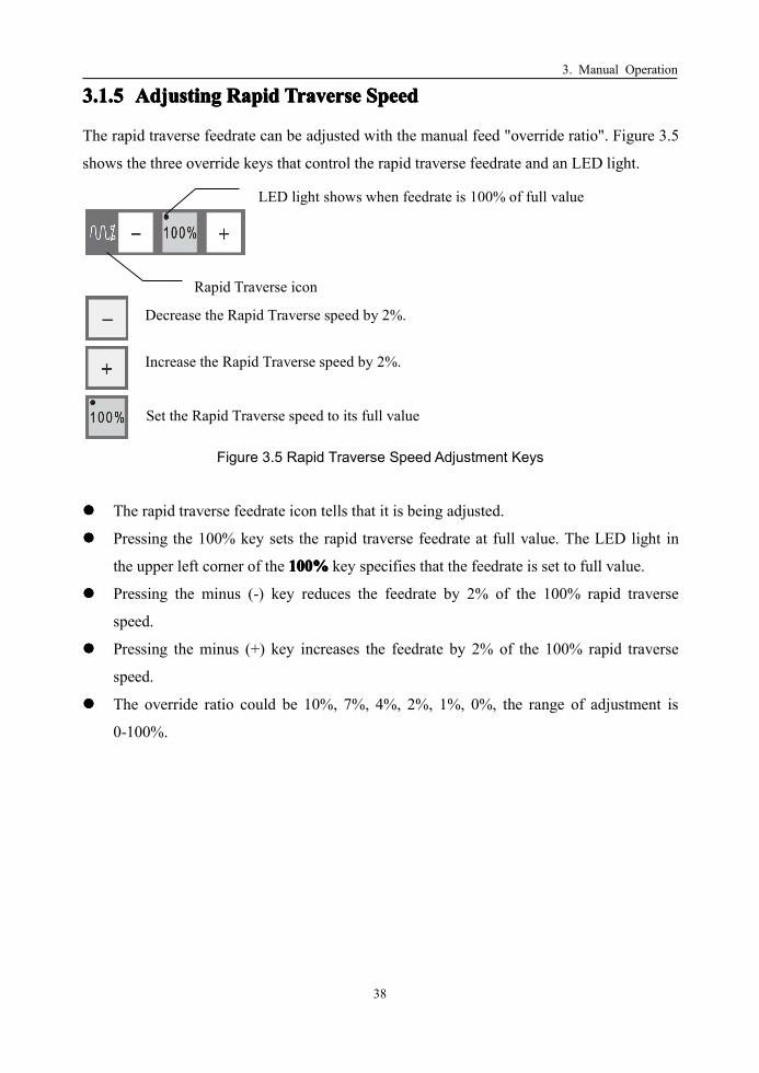
3.1.53.1.53.1.53.1.5 AdjustingAdjustingAdjustingAdjusting RapidRapidRapidRapid TraverseTraverseTraverseTraverse SpeedSpeedSpeedSpeed
The rapid traverse feedrate can be adjusted with the manual feed "override ratio". Figure 3.5
shows the three override keys that control the rapid traverse feedrate and an LED light.
Set the Rapid Traverse speed to its full value
Increase the Rapid Traverse speed by 2%.
Decrease the Rapid Traverse speed by 2%.
LED light shows when feedrate is 100% of full value
Rapid Traverse icon
Figure 3.5 Rapid Traverse Speed Adjustment Keys
���� The rapid traverse feedrate icon tells that it is being adjusted.
���� Pressing the 100% key sets the rapid traverse feedrate at full value. The LED light in
the upper left corner of the 100%100%100%100% key specifies that the feedrate is set to full value.
���� Pressing the minus (-) key reduces the feedrate by 2% of the 100% rapid traverse
speed.
���� Pressing the minus (+) key increases the feedrate by 2% of the 100% rapid traverse
speed.
���� The override ratio could be 10%, 7%, 4%, 2%, 1%, 0%, the range of adjustment is
0-100%.

3. Manual Operation
39
3.23.23.23.2 IncrementalIncrementalIncrementalIncremental FeedFeedFeedFeedThe INC feed is useful for adjusting the cutting tool a small fixed amount from a surface
being turned or faced. For example, in making a sample turning cut, the cutting tool can be
adjusted toward the workpiece until it just begins to cut. Then using a small (say 5 thou)
incremental -X movement let the operator clean up surface of the workpiece by removing 5
thou from the diameter.
3.2.13.2.13.2.13.2.1 RequirementRequirementRequirementRequirement
Figure 3.6 shows the increment mode key.
INCINCINCINC mode key
INCINCINCINC mode LED indicator light
Figure 3.6 Incremental Mode Key
���� Switch to INCINCINCINC mode by pressing the INC mode key on the Machine Control Panel.
� After pressing the INCINCINCINC mode button, the LED indicator light on that key lights to verify
that it is in the INCINCINCINC mode.

3. Manual Operation
40
3.2.23.2.23.2.23.2.2 IncrementalIncrementalIncrementalIncremental FeedrateFeedrateFeedrateFeedrate
Incremental feed is used to move an axis at a fixed increment of travel. In INC mode, the
cutting tool moves at the JOG feedrate. Pressing an axis key in incremental or INCINCINCINC mode,
moves the cutting tool one increment in that axis and direction.
Figure 3.7 shows the feed axis keys in incremental mode.
This key moves the X axis one step in the positivedirection (awayawayawayaway fromfromfromfrom the workpiece)
This key moves the X axis one step in the negativedirection (towardtowardtowardtoward the workpiece)
Figure 3.7 Feed Axis Keys in Incremental Mode
� For each press of the feed axis keys: +X, -X, +Y, -Y, +Z or -Z, the tool cutter moves a
certain distance. If your milling has a fourth axis (4TH axis), you can also press the
+4TH or -4TH keys. To move the cutting tool toward the workpiece use a minus key
(-X, -Y, -Z, -4TH). For moving the cutting tool away from the workpiece use a plus key
(+X, +Y, +Z, +4TH).
� The distance is the number of minimum steps multiplied by the magnifier value. For
example, if the magnifier were set at 1 and you pressed the +X key twice, the distance
moved would be stepminimum221 =× . In inch units, that's a tenth of a thou, in
metric units that's 2 microns. But if the magnifier were set at 100, the distance moved
would be step minimum2002100 =× . In inch units, it moves ten thou (0.012inch),
in metric units it moves 200 microns (0.2mm).

3. Manual Operation
41
3.2.33.2.33.2.33.2.3 StepStepStepStep LengthLengthLengthLength
As it is mentioned above, in incremental mode, pressing an axis key on the Machine Control
Panel moves the tool one step along the selected axis in the selected direction.
The step length is a “magnified” length. The distance moved in a step length is the
minimum step multiplied by the magnifier value:
magnifierstep minimumlengthstep ×=
� Minimum step
The “minimum step” is the shortest distance that an axis can move. The minimum step is a
certain rotation of the ball screw moving each axis. It is determined by the machine's
encoder. Depending on the number of steps on that axes' encoder, the step size is either in
inch or metric units. For an inch unit encoder, the minimum step is 50 millionths of an inch
(half a tenth of a thou). For a metric unit encoder, the minimum step is 1 micron (0.001
mm).
� Magnifier
The four keys below (Figure 3.8) are the step length magnification in the INCINCINCINC mode.
Pressing any key changes the magnification of the corresponding distance. The minimum
step can be magnified by 1, 10, 100, or 1000 times giving a "step length". As before, the
LED light associated with the selection lights up indicating which magnification is chosen.
LED light shows which magnification is selected
Magnifier
No magnification; each key press moves one minimum step.
Each key press moves ten minimum steps.
Each key press moves one hundred minimum steps.
Each key press moves one thousand minimum steps.
Figure 3.8 Step Length Magnification

3. Manual Operation
42
3.33.33.33.3 ManualManualManualManual HandwheelHandwheelHandwheelHandwheelIn the handwheel mode, the cutting tool can be moved at the small amounts by rotating the
handwheel on the handwheel unit (Figure 3.9). During part setup with the handwheel, the
operator can adjust the cutting tool closer to the workpiece than from the machine control
panel. There are two selection knob on the handwheel unit: one is for axis selection (X,X,X,X, Y,Y,Y,Y, Z,Z,Z,Z,
4TH4TH4TH4TH) and the other is for magnification (X1,X1,X1,X1, X10,X10,X10,X10, X100,X100,X100,X100, X1000X1000X1000X1000).
Handwheel unit
Magnification selection knob
Axis selection/OFF knob
Handwheel
Figure 3.9 Hand Pendant
3.3.13.3.13.3.13.3.1 RequirementRequirementRequirementRequirement
To use the handwheel unit, the machine should be in the incremental mode.
� press the INCINCINCINC mode key . When the handwheel is enabled, the INCINCINCINC mode on the
machine control panel is disabled (i.e., the incremental feed operation is disabled).
� Once in INCINCINCINC mode, the handwheel unit is activated by turning the Axis Selection knob
from the OFF position to one of the milling's axes.

3. Manual Operation
43
3.3.23.3.23.3.23.3.2 AxisAxisAxisAxis SSSSelection/Oelection/Oelection/Oelection/Offffffff KKKKnobnobnobnob
The following figure shows the Axis selection/Off knob on the handwheel unit. By rotating
the knob, you both turn on the Handwheel unit and also select the axis of handwheel motion.
OFF:OFF:OFF:OFF: The handwheel unit is disabled; control is through theincremental mode on the machine control panel.
X:X:X:X: Handwheel movement controls the X axis
YYYY:::: Handwheel movement controls the Y axis
Z:Z:Z:Z: Handwheel movement controls the Z axis.
4TH4TH4TH4TH:::: Handwheel movement controls the 4TH axis (if available).
Figure 3.10 Axis Selection/Off Knob
3.3.33.3.33.3.33.3.3 MagnificationMagnificationMagnificationMagnification SelectionSelectionSelectionSelection KnobKnobKnobKnob
The right knob on the Handwheel unit is the Magnification Selection knob (Figure 3.11). By
rotating the knob, you select the amount of magnification to the step length for each
increment of handwheel motion. The amount of magnification can be 1, 10, 100 or 1000.
X1:X1:X1:X1: No magnification; each click of the handwheel moves one minimum step.
X10X10X10X10: Each click of the handwheel moves ten minimum steps.
X100X100X100X100: Each click of the handwheel moves a hundred minimum steps.
X1000X1000X1000X1000: Each click of the handwheel moves a thousand minimum steps.
Figure 3.11 Magnification Selection Knob
Note:Note:Note:Note: A minimum step for linear axes is 0.5 tenths (inch encoders), one micron (metric
encoders) or 0.001 degrees for rotational axes.

3. Manual Operation
44
3.3.43.3.43.3.43.3.4 HandwheelHandwheelHandwheelHandwheel RotationRotationRotationRotation
Rotating the handwheel on the handwheel unit moves the selected axis one step length
(minimum step * magnifier) for each click of the handwheel. Clockwise rotation moves the
selected axis awayawayawayaway fromfromfromfrom the workpiece (positive axis direction: +X,+X,+X,+X, +Y,+Y,+Y,+Y, +Z,+Z,+Z,+Z, ++++4TH4TH4TH4TH).
Counter-clockwise rotation moves the selected axis towardtowardtowardtoward the workpiece (negative axis
direction: -X,X,X,X, -Y,-Y,-Y,-Y, -Z,-Z,-Z,-Z, ----4TH4TH4TH4TH)))). Always be cautious when moving the handwheel
counter-clockwise because you are moving it toward the cutting zone.
ClockwiseClockwiseClockwiseClockwise RotationRotationRotationRotation (CW):(CW):(CW):(CW): Moves the cutting tool awayawayawayaway fromfromfromfromthe workpiece (i.e., positive axis direction) on the selected axis.
Counter-clockwiseCounter-clockwiseCounter-clockwiseCounter-clockwise RotationRotationRotationRotation (CCW):(CCW):(CCW):(CCW): Moves the cutting tooltowardtowardtowardtoward the workpiece (i.e. negative axis direction) on theselected axis.
StepStepStepStep length:length:length:length: The motion is one step length (minimum steptimes the magnifier) per click of the handwheel.
Figure 3.12 Handwheel
3. Manual Operation
45
3.43.43.43.4 SpindleSpindleSpindleSpindle OperationOperationOperationOperationThe spindle is the most important of these keys since no cutting takes place unless the
spindle is rotating. For most millings, the spindle can be manually operated when the
milling is not machining. However, some milling manufacturers do not allow manual
operation of the spindle except in JOG mode.
3.4.13.4.13.4.13.4.1 RequirementsRequirementsRequirementsRequirements
The machine should be in JOG mode.
� Switch to Jog mode by pressing the JOG mode key .
� After pressing the Jog mode button, the LED indicator light on that key lights to verify
that you are in the Jog mode. Make sure there is no potential danger from the spindle
turning before you run the spindle manually.

3. Manual Operation
46
3.4.23.4.23.4.23.4.2 SpindleSpindleSpindleSpindle ControlControlControlControl KeysKeysKeysKeys
The four keys shown below (Figure 3.13) control the spindle operation. The lower left key
starts spindle rotation in the clockwise (CWCWCWCW) direction, the middle key stops the spindle
manually and the right key starts spindle rotation in the counter-clockwise (CCWCCWCCWCCW) direction.
The upper spindle key turns on the spindle as long as it is pressed.
RUNRUNRUNRUN SPINDLESPINDLESPINDLESPINDLE CCW:CCW:CCW:CCW: Rotate the spindle incounter-clockwise direction. The LED is lit if thespindle is running.
RUNRUNRUNRUN SPINDLESPINDLESPINDLESPINDLE CW:CW:CW:CW: Rotate the spindle in clockwiseclockwiseclockwiseclockwisedirection. The LED is lit if the spindle is running.
STOPSTOPSTOPSTOPSPINDLE:SPINDLE:SPINDLE:SPINDLE: Stop the spindle manually.
SPINDLESPINDLESPINDLESPINDLE ORIENTATION:ORIENTATION:ORIENTATION:ORIENTATION: Press this key to let thespindle approach a certain position that can align thespindle to its seat.
SPINDLESPINDLESPINDLESPINDLE BRAKE:BRAKE:BRAKE:BRAKE: Pressing down this key will brakethe spindle.
SPINDLESPINDLESPINDLESPINDLE JOG:JOG:JOG:JOG: Spindle rotates only while pressingthis key. Spindle stops when key is released.
Figure 3.13 Spindle Control Keys
Note:Note:Note:Note: If the spindle is turning one way and you want to change the rotation direction to the
other way, you must first stop it and then press the desired rotation direction.

3. Manual Operation
47
3.4.33.4.33.4.33.4.3 AdjustingAdjustingAdjustingAdjusting SpindleSpindleSpindleSpindle SpeedSpeedSpeedSpeed
The spindle speed can be adjusted with the manual feed "override ratio". Figure 3.14 shows
the three override keys that control the spindle speed and an LED light.
Set the spindle speed to its full value
Increase the spindle speed by 2%.
Decrease the spindle speed by 2%.
Spindle icon
LED light shows when feedrate is 100% of full value
Figure 3.14 Spindle Speed Adjustment Keys
���� The spindle icon tells that it is being adjusted.
���� Pressing the 100% key sets the spindle speed at full value. The LED light in the upper
left corner of the 100%100%100%100% key specifies that the spindle speed is set to full value.
���� Pressing the minus (-) key reduces the speed by 2% of the factory default amount of the
100% spindle speed.
���� Pressing the minus (+) key increases the speed by 2% of the factory default amount of
the 100% spindle speed.
���� The override ratio could be 10%, 7%, 4%, 2%, 1%, 0%, the range of adjustment is
0-150%.

3. Manual Operation
48
3.53.53.53.5 AuxiliaryAuxiliaryAuxiliaryAuxiliary OperationOperationOperationOperationTo operate the auxiliary devices: coolant, and tool selection, there are three keys.
3.5.13.5.13.5.13.5.1 RequirementsRequirementsRequirementsRequirements
The machine must be in JOGJOGJOGJOG mode.
� Switch to JOGJOGJOGJOGmode by pressing on the JOGJOGJOGJOG key .
� After pressing the JOGJOGJOGJOG mode button, the LED indicator light on that key lights to verify
that it is in the JOGJOGJOGJOG mode.
3.5.23.5.23.5.23.5.2 AAAAuxiliaryuxiliaryuxiliaryuxiliary KeysKeysKeysKeys
The three keys shown below control auxiliary operation. The first key turns coolant flow
on/off. The other two keys are for the tool exchange and tool lock/unlock.
COOLANTCOOLANTCOOLANTCOOLANT ON/OFF:ON/OFF:ON/OFF:ON/OFF: Press this key to start coolant flow. Coolantflow is ON if the LED light is lit and OFF if the LED light is off.
TOOLTOOLTOOLTOOL LOCK/UNLOCK:LOCK/UNLOCK:LOCK/UNLOCK:LOCK/UNLOCK: Provided the tool is exchangeable, oncethis key is pressed, the tool will be released if it is locked before andwill be locked if it is to be replaced.
TOOLTOOLTOOLTOOLEXCHANGEEXCHANGEEXCHANGEEXCHANGE ENABLE:ENABLE:ENABLE:ENABLE: This key is to enable or disable thetool exchange operation. The tool is exchangeable while the LEDlamp on this key’s upper left corner is on. Otherwise, the toolexchange operation is not permitted.
Coolant keyTool exchange keys
Figure 3.15 Auxiliary Keys

4. Automatic Operation
49
4444 AutomaticAutomaticAutomaticAutomatic OperationOperationOperationOperationAutomatic (AUTOAUTOAUTOAUTO) operation is used to machine parts under program control. In an NC
machine tool, most production machining is done as an AUTOAUTOAUTOAUTO operation. In Automatic
mode, you can execute part programs automatically. If you are a manual milling operator, it
is the AUTOAUTOAUTOAUTO operations that will be most unfamiliar to you.
AUTOAUTOAUTOAUTO operation requires a program to execute. Several sample programs are already
included in the controller's memory. If you are a beginner, execute one of the sample
programs in AUTOAUTOAUTOAUTO mode. If you are an advanced NC operator, execute a program that you
have written yourself.
Automatic operation includes four parts:
1) ProgramProgramProgramProgram LoadingLoadingLoadingLoading: putting the program into the milling’s computer memory
2) ProgramProgramProgramProgramVerifyingVerifyingVerifyingVerifying: finding errors in a new program
3) RunningRunningRunningRunning Control:Control:Control:Control: running part of the program to debug it
4) ManualManualManualManual DataDataDataData InputInputInputInput (MDI):(MDI):(MDI):(MDI): operating the milling by typing blocks into the
milling’s computer manually.

4. Automatic Operation
50
4.14.14.14.1 RequirementsRequirementsRequirementsRequirementsThe requirements below are all necessary before the milling can be run automatically.
� Programming functions require “soft keys”. These are keys whose function changes
depending on the key’s description on the LCD screen. The physical keys are located
just below the LCD screen. Each soft key function shown on the LCD screen is
actuated by pushing the corresponding physical key just below. After pressing the
physical key, the soft key descriptions will change to bring in functions only available
when the physical key is pressed.
Soft key description on LCD screen
LCD Screen
Physical keys
Corresponding physical key
Figure 4.1 Soft Keys
� The milling has already been homed. That is, the “Reference Point Approach”
procedure has been completed.
� You have verified or entered tool data (offset and compensation values), zero offsets
and other necessary data.
� Machine lock is off.
� Machine should be in AUTOAUTOAUTOAUTO mode.
AUTOAUTOAUTOAUTO mode key
AUTOAUTOAUTOAUTO mode LED indicator light
Figure 4.2 Automatic Mode Key

4. Automatic Operation
51
4.24.24.24.2 ProgramProgramProgramProgram LoadingLoadingLoadingLoadingA program file must be “loaded” into the milling’s memory before it can be “executed” (i.e.,
cut a part or do some other operations automatically). The program file itself is a series of
program lines called blocks that direct the milling through a series of various operations
automatically. The programmer who writes the program file sets these operations.
Only one program at a time can be “loaded” for execution by the milling. Usually many
programs that have been written are stored in the milling’s computer. “Loading” is the
process of picking one of these programs to be executed.
The following steps are to load a program for execution.
1) From the physical Menu keys located just below the LCD screen, press the F1
physical key just below the F1 [[[[PROGPROGPROGPROG]]]] soft key on the LCD screen. Then the soft
keys would change to ProgramProgramProgramProgram FunctionsFunctionsFunctionsFunctions and ProgramProgramProgramProgram SourcesSourcesSourcesSources. These functions
only appear after pressing the F1 PROGPROGPROGPROG key.
F1 PROGPROGPROGPROG soft key
LCD Screen
ProgramProgramProgramProgram FunctionsFunctionsFunctionsFunctions
ProgramProgramProgramProgram sourcessourcessourcessources
Figure 4.3 The sequence of program loading (1)

4. Automatic Operation
52
2) Now press the F1 physical key again, corresponding to the F1 [[[[OPENOPENOPENOPEN]]]] soft key.
F1 OPENOPENOPENOPEN soft key
Figure 4.4 The sequence of program loading (2)
3) When pressing the OPENOPENOPENOPEN soft key, the LCD screen shows a file directory: a list of
program files is like the ones below. The left column shows the name of the
program file, the middle column shows the size of the file and the rightmost file
shows the last date the file was changed. NoteNoteNoteNote that program files always start with
the letter “O”. The example below shows 10 different program files, each 1K long
(one kilobyte) and last changed in Dec. 2006.
Programfiledirectory
Figure 4.5 The sequence of program loading (3)
4) Use the left-right keys (located on the keyboard area just to the right
of the LCD screen) to change the selected item from among the ProgramProgramProgramProgram Sources:Sources:Sources:Sources:
CF (hard disk or memory chip), DNC and floppy disk.
Selected source shows in blue color
Figure 4.6 The sequence of program loading (4)
5) Once the source is selected, use the up-down keys to select one of
the program files from the program file directory. Each press of the down key
moves the blue selected line to the next file down in the file listing.
6) Last, press the EnterEnterEnterEnter key in lower right corner of the keyboard area to load the
selected program to memory.

4. Automatic Operation
53
4.34.34.34.3 ProgramProgramProgramProgram VerifyingVerifyingVerifyingVerifyingA program which has just been created or changed should be verified before it is actually
used to cut parts. Program verifying can find errors in the program without actually running
the machine and possibly damaging the milling or the workpiece.
The following steps are used to verify a program:
1) Load the program to the milling’s computer memory as shown above.
2) To verify, you must be in either AUTO mode (Automatic mode) or SBL
mode (Single Block mode).
3) Press the F5 key corresponding to VERIFYVERIFYVERIFYVERIFY in the ProgramProgramProgramProgram FunctionsFunctionsFunctionsFunctions menu.
ProgramProgramProgramProgram FunctionsFunctionsFunctionsFunctions
F5 VERIFYVERIFYVERIFYVERIFY soft key
Figure 4.7 The sequence of program verifying (1)
4) In VERIFYVERIFYVERIFYVERIFY mode, the soft key display changes to the one below where the
functions VERIFYVERIFYVERIFYVERIFY and PAUSEPAUSEPAUSEPAUSE are in bold type. The other functions are in light
type, signifying that they can not be used during the VERIFYVERIFYVERIFYVERIFY process.
Figure 4.8 The sequence of program verifying (2)
5) Press the CycleCycleCycleCycle RunRunRunRun button on the Machine Control Panel (MCP) to start the
VERIFYVERIFYVERIFYVERIFY process.
Figure 4.9 The sequence of program verifying (3)

4. Automatic Operation
54
6) As the program is verified, the lines of the program are displayed. The line being
verified is highlighted in yellow. As the verification progresses, the yellow line
moves line-by-line from the top to the bottom of the program. The LCD screen
will display an error message if an error is found. Otherwise the cursor (yellow
highlighted line) will return to the start of the program.
Figure 4.10 The sequence of program verifying (4)
7) Note that there is no motion of the cutter or any other action that takes place. The
VERIFYVERIFYVERIFYVERIFY process is a simulation of the motion or action that would take place.
8) View different settings of the LCD display using Program Function F9 VIEWVIEWVIEWVIEW.
For example, you can observe the cutting tool motion with the graphics display
view or you can observe the position of the axes and feedrate with the axis display
view.

4. Automatic Operation
55
4.44.44.44.4 RunningRunningRunningRunning ControlControlControlControlOnce verified successfully, the program can be executed automatically with AUTOAUTOAUTOAUTO mode
or by stepping through each block of the program in SBLSBLSBLSBL mode . Most
operators will step through the program in Single Block (SBLSBLSBLSBL) mode before trying it in
AUTOAUTOAUTOAUTO mode.
The program running process – either verifying or executing – can be paused, canceled or
run from the start again. You can also run the program from a specific location in the
program other than from its start to more easily confirm the program section at a time.
The following steps are used to run a program:
1) From the Main Menu, press the F2 RUNRUNRUNRUN CTRLCTRLCTRLCTRL soft key.
F2 RUNRUNRUNRUN CTRLCTRLCTRLCTRL soft key
LCD Screen
Figure 4.11 The sequence of running a program (1)
2) If you are in a submenu, press the F10 BACKTOBACKTOBACKTOBACKTO MAINMAINMAINMAIN soft key (the rightmost
key on all submenus). For example, from the VERIFYVERIFYVERIFYVERIFY submenu below, press F10
BACKTOBACKTOBACKTOBACKTOMAINMAINMAINMAIN to return to the Main Menu above.
F10 BACKTOBACKTOBACKTOBACKTOMAINMAINMAINMAIN soft key
Figure 4.12 The sequence of running a program (2)

4. Automatic Operation
56
Running Control has nine different operations available:
1) CycleCycleCycleCycle RunRunRunRun: cycles through the program
2) FeedFeedFeedFeed Hold:Hold:Hold:Hold: stop the motion of the program with a soft key press
3) PausePausePausePause Processing:Processing:Processing:Processing: pause the program’s operation
4) Restart:Restart:Restart:Restart: begin the program operation again after a pause
5) PickPickPickPick StartStartStartStart Block:Block:Block:Block: begin the program at any line
6) SaveSaveSaveSave BreakBreakBreakBreak Point:Point:Point:Point: shut down the machine and save the restart point
7) LoadLoadLoadLoad BreakBreakBreakBreak Point:Point:Point:Point: load the restart point after machine shutdown
8) BreakBreakBreakBreak PointPointPointPoint recover:recover:recover:recover: restart after machine shutdown
9) AlignAlignAlignAlign Tool:Tool:Tool:Tool: change tools and realign the new cutter at the same location

4. Automatic Operation
57
4.4.14.4.14.4.14.4.1 CycleCycleCycleCycle RunRunRunRun
This function begins program execution.
� RequirementsRequirementsRequirementsRequirements
1) The program has been successfully verified
2) The machine is in Single Block (SBLSBLSBLSBL) mode or Automatic (AUTOAUTOAUTOAUTO) mode.
���� SequenceSequenceSequenceSequence
1) Press the green CycleCycleCycleCycle RunRunRunRun button and the program will be executed.
2) If the machine is in AUTOAUTOAUTOAUTO mode, the machine will keep running until it is finished
or until the FFFFeedeedeedeed HHHHoldoldoldold button is pressed to cancel the AUTOAUTOAUTOAUTO mode.
3) If the machine is in SBLSBLSBLSBL mode, the machine stops after each block of the program
is executed. Press CycleCycleCycleCycle RunRunRunRun again and the next block in the program will be
executed.
4. Automatic Operation
58
4.4.24.4.24.4.24.4.2 FeedFeedFeedFeed HoldHoldHoldHold
���� RequirementRequirementRequirementRequirement
1) The program has been successfully verified.
2) The machine is in Single Block (SBLSBLSBLSBL) mode or Automatic (AUTOAUTOAUTOAUTO) mode.
���� SequenceSequenceSequenceSequence
1) During execution, pressing the red FeedFeedFeedFeed HHHHoldoldoldold button pauses the program.
Pressing the CycleCycleCycleCycle RunRunRunRun button recovers the running process again. These two –
CycleCycleCycleCycle RunRunRunRun and FeedFeedFeedFeed HHHHoldoldoldold – work together to stop and restart the program being
executed.
2) After the FeedFeedFeedFeed HHHHoldoldoldold button is pressed, you can stop all action by pressing the
EmergencyEmergencyEmergencyEmergency StopStopStopStop button. If you just want to exit the program, cancel it with the
PAUSEPAUSEPAUSEPAUSE operation below.

4. Automatic Operation
59
4.4.34.4.34.4.34.4.3 PausePausePausePause ProcessingProcessingProcessingProcessing
The milling’s computer begins processing the program once it is loaded into the memory.
You can pause the processing by pressing F6 [PAUSEPAUSEPAUSEPAUSE] in the ProgramProgramProgramProgram FunctionsFunctionsFunctionsFunctions
submenu.
Prompt on blue background
PAUSEPAUSEPAUSEPAUSE soft key pressed
Figure 4.13 Pause Processing
1) Press F6 PAUSEPAUSEPAUSEPAUSE and the program pauses and issues a prompt (words in green
with blue background) asking the operator a question.
2) Pressing the YYYY (Yes) key on the NC keyboard cancels the program. All the current
mode information will be unloaded. The program can not run from this point
3) Pressing the NNNN (No) key pauses the program; it can be run again from the stopping
point by pressing the RESTARTRESTARTRESTARTRESTART soft key.

4. Automatic Operation
60
4.4.44.4.44.4.44.4.4 RestartRestartRestartRestart
If the program has been canceled by pressing YYYY (Yes) after the Pause soft key prompt,
restart from the program beginning by pressing the RESTARTRESTARTRESTARTRESTART soft key.
RESTARTRESTARTRESTARTRESTART prompt
Press RESTARTRESTARTRESTARTRESTART soft key
Figure 4.14 Restart a Program
1) Press F7 RESTARTRESTARTRESTARTRESTART
2) Press NNNN (No) to cancel RESTARTRESTARTRESTARTRESTART.
3) Answer YYYY (Yes) on the NC keyboard to run the program again from the beginning.
4) Now press the CycleCycleCycleCycle RunRunRunRun button on the Manual Control Panel (MCP) and the
program will be executed from the beginning.
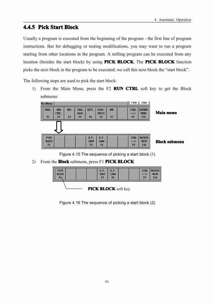
4. Automatic Operation
61
4.4.54.4.54.4.54.4.5 PickPickPickPick StartStartStartStart BlockBlockBlockBlock
Usually a program is executed from the beginning of the program - the first line of program
instructions. But for debugging or testing modifications, you may want to run a program
starting from other locations in the program. A milling program can be executed from any
location (besides the start block) by using PICKPICKPICKPICK BLOCKBLOCKBLOCKBLOCK. The PICKPICKPICKPICK BLOCKBLOCKBLOCKBLOCK function
picks the next block in the program to be executed; we call this next block the “start block”.
The following steps are used to pick the start block:
1) From the Main Menu, press the F2 RUNRUNRUNRUN CTRLCTRLCTRLCTRL soft key to get the Block
submenu:
MainMainMainMain menumenumenumenu
BlockBlockBlockBlock submenusubmenusubmenusubmenu
Figure 4.15 The sequence of picking a start block (1)
2) From the BlockBlockBlockBlock submenu, press F1 PICKPICKPICKPICK BLOCKBLOCKBLOCKBLOCK
PICKPICKPICKPICK BLOCKBLOCKBLOCKBLOCK soft key
Figure 4.16 The sequence of picking a start block (2)

4. Automatic Operation
62
3) A dialog window appears on the LCD screen giving instructions for the next
operation. Now you have three choices.
Press the F3 soft key to use the currentline as the start block
Press the F2 soft key tospecify the start block
Press the F1 soft key to use the“red” line as the start block
Figure 4.17 The sequence of picking a start block (3)
� Press F1: Start block is shown by the red bar. Use the Up/Down keys
to move the red bar up or down to the desired start block.
Figure 4.18 The sequence of picking a start block (4)
� Press F2: Start block specified by its line (row) number. For example, in the
program above, to select “G80 X25 Z-20 F2000” as the start block, type 7777
(seventh line) after pressing F2
Figure 4.19 The sequence of picking a start block (5)
� Press F3: Start block is the current block shown by the blue bar
4) Press the F9 VIEWVIEWVIEWVIEW key to cycle through different views until you come to the
program view shown above.
5) Press the CycleCycleCycleCycle RunRunRunRun button to begin execution at the start block

4. Automatic Operation
63
For complex or large parts, more than one day may be required to finish machining. You
may need to turn off the machine before it’s done. In this case, the milling’s memory should
store the current block location and recover from this location to continue machining later.
Break point functions do this. In order to save the location for restarting the program later,
you need to know three procedures: savingsavingsavingsaving the break point when you stop, loadingloadingloadingloading the
saved break point and recoveringrecoveringrecoveringrecovering from the break.
4.4.64.4.64.4.64.4.6 B.P.B.P.B.P.B.P. SaveSaveSaveSave
The first of the three break point functions is saving the break point when you stop the
milling.
The following steps are to save the break point:
1) Press FeedFeedFeedFeed HoldHoldHoldHold button to pause the machine.
2) Press F2 RUNRUNRUNRUN CTRLCTRLCTRLCTRL from the Main Menu to get the Block submenu
MainMainMainMain menumenumenumenu
BlockBlockBlockBlock submenusubmenusubmenusubmenu
Figure 4.20 The sequence of saving a break point (1)
3) Press the F5 B.P.B.P.B.P.B.P. SAVESAVESAVESAVE soft key to save the break point. Notice that the soft key
turns green when the function is entered.
B.P.B.P.B.P.B.P. SAVESAVESAVESAVE soft key
Figure 4.21 The sequence of saving a break point (2)

4. Automatic Operation
64
4) Type the break point file name using the keyboard to the right of the LCD screen.
In the example below, the file is named “03453.BP1” perhaps naming the part
number being machined.
Figure 4.22 The sequence of saving a break point (3)
5) Press EnterEnterEnterEnter to confirm the operation. The milling will store the current status
information to the typed file.
4.4.74.4.74.4.74.4.7 B.P.B.P.B.P.B.P. LOADLOADLOADLOAD
If you haven’t turned the milling power off after the B.P. SAVE, you can restore the
breakpoint directly with B.P. LOAD. For example, if you just leave for a lunch break, you
can do a B.P. SAVE before you leave and then resume again quickly when you return.
However, if machine has been powered off after a B.P. SAVE operation, you must recover
the break point: first the milling must be homed (i.e., perform the “Reference Point
Approach” procedure) after turning the power on. Since the workpiece will still be in the
chuck, you should be careful on which axis you home first (X, Z and perhaps C) to avoid a
collision between the cutting tool and the workpiece.
The following steps are to load a break point:
1) The break point program has been loaded into memory
2) Press F2 RUNRUNRUNRUN CTRLCTRLCTRLCTRL from the Main Menu to get the Block submenu.
MainMainMainMain menumenumenumenu
BlockBlockBlockBlock submenusubmenusubmenusubmenu
Figure 4.23 The sequence of loading a break point (1)

4. Automatic Operation
65
3) Press the F6 B.P.B.P.B.P.B.P. LOADLOADLOADLOAD soft key to load the break point file.
B.P.B.P.B.P.B.P. LOADLOADLOADLOAD soft key
Figure 4.24 The sequence of loading a break point (2)
4) After pressing the B.P.B.P.B.P.B.P. LOADLOADLOADLOAD soft key, a table of break point files is displayed.
The first column is the name of the file, the second is the size of the file in
Kilobytes and the last column is the date on which the break point file was last
saved.
B.P.B.P.B.P.B.P. LOADLOADLOADLOADfunction
Break pointfile name Size in Kilobytes
Date last saved
Figure 4.25 The sequence of loading a break point (3)
5) Use the up/down keys to select the desired break point file.
6) Press EnterEnterEnterEnter to confirm your selection
7) If there were absolutely no changes since the B.P. SAVE operation, press CycleCycleCycleCycle RunRunRunRun
button to continue the machining process. Otherwise switch to the MDIMDIMDIMDI mode to
recover the breakpoint.

4. Automatic Operation
66
4.4.84.4.84.4.84.4.8 B.P.B.P.B.P.B.P. RecoveryRecoveryRecoveryRecovery
If there have been ANY manual operations of the milling or if the milling power has been
turned off, you must move the tool back to where it was before the break point in order to
run the machine again using the break point file.
The following steps are to recover a break point:
1) Move the cutting tool near its position at the break point, making sure there won’t be a
collision during this operation.
2) Switch to the MDIMDIMDIMDI mode by first returning to the Main Menu. Press F10 BACKBACKBACKBACK TOTOTOTO
MAINMAINMAINMAIN, then press F3 MDIMDIMDIMDI.
F3 MDIMDIMDIMDIsoft key
F7 GOGOGOGOTOTOTOTOB.P.B.P.B.P.B.P. soft key
F10 BACKBACKBACKBACK TOTOTOTOMAINMAINMAINMAIN soft key
Figure 4.26 The sequence of recovering a break point
3) Press the F7 GOGOGOGO TOTOTOTO B.P.B.P.B.P.B.P. soft key
4) Now press the CycleCycleCycleCycle RunRunRunRun button on the Manual Control Panel (MCP). The milling
will go automatically to the break point position when it was saved before
power-off.
5) Press F10 BACKBACKBACKBACK TOTOTOTOMAINMAINMAINMAIN again to exit the MDIMDIMDIMDI mode.
6) After the machine has stopped at the saved break point, press the CycleCycleCycleCycle RunRunRunRun
button to continue machining from the saved break point.

4. Automatic Operation
67
4.4.94.4.94.4.94.4.9 AAAAlignlignlignlign ToolToolToolTool
Another use of break points is when the cutter gets dull and the milling must be stopped to
change cutters. To install a new cutter you first stop the milling and B.P.B.P.B.P.B.P. SAVESAVESAVESAVE before you
remove the old cutter. However, when you put the new cutter back into the tool holder, the
tool must be realigned so the new cutter is at the same position as the old one.
The following steps are to align tool:
1) Move the new tool near the position of the break point, making sure the cutter
could not collide with the workpiece or fixture during this operation.
2) Switch to the MDIMDIMDIMDI mode from the Main Menu and press F8 ALIGNALIGNALIGNALIGN TOOLTOOLTOOLTOOL:
F3 MDIMDIMDIMDIsoft key
F8 ALIGNALIGNALIGNALIGN TOOLTOOLTOOLTOOLsoft key
Figure 4.27 Align Tool
3) Press the CycleCycleCycleCycle RunRunRunRun button on the Manual Control Panel (MCP). The milling will
align the tool automatically and update the tool data.
4) Press F10 BACKBACKBACKBACK TOTOTOTOMAINMAINMAINMAIN in order to exit the MDIMDIMDIMDI mode.
5) After the machine has finished the tool alignment operation, press the CycleCycleCycleCycle RunRunRunRun
button to continue machining from the break point.

4. Automatic Operation
68
4.54.54.54.5 MDIMDIMDIMDI OperationOperationOperationOperationThe Manual Data Input (MDIMDIMDIMDI) mode is used to set milling data values and operations
without using a program. G-codes, M-codes and T-codes can all be entered manually
through the keyboard. The MDIMDIMDIMDI mode is useful not only for break point recovery as was
done above.
The following steps are about MDI operation.
1) From the Main Menu, press F3 MDIMDIMDIMDI and the milling will enter into MDIMDIMDIMDI mode.
F3 MDIMDIMDIMDI soft key
Figure 4.28 MDI mode
2) The MDI screen shows the previously executed G-codes which set the function of
the milling. Also shown are values of different parameters such as feedrate,
spindle speed and axis position.
MDIMDIMDIMDI screen
MDIMDIMDIMDI RUNRUNRUNRUN Command Input line
Previously executed G-code listParameter values
Figure 4.29 MDI screen

4. Automatic Operation
69
3) Input one or several commands representing one block of data on the MDI RUN
command input line. In this example, the manually input G-code commands will
set the milling for linear interpolation (G01), set the X position from zero to 100
(X100), and set the feedrate from 500 to 1000 (F1000). Note that only one block
of commands can be executed for each cycle run.
MDIMDIMDIMDI RUNRUNRUNRUN command Input line
Multiple commands form one block of data
Figure 4.30 MDI RUN command
4) Press EnterEnterEnterEnter to confirm the commands. In the example from above, the G01
command replaces the previous G00 command, the X axis has a new position of
100 instead of zero and the feedrate has a new value of 1000 instead of 500.
New X axis position valueNew G-code
New feedrate value
Figure 4.31 new MDI screen
5) Press CycleCycleCycleCycle RunRunRunRun button to execute the commands.

5. Program File Operation
70
5555 ProgramProgramProgramProgram FileFileFileFile OperationOperationOperationOperationProgram can be stored in CF, floppy Disk and hard disk. From Main menu, press F1, the
program file management menu is displayed.
Figure 5.1 Program File Management
Functions:Functions:Functions:Functions:
1) F1[OPEN]: Open a program file saved in CF, DNC or floppy disk.
2) F2 [EDIT]�F3[NEW]: Create a new file.
3) F2[EDIT]: Edit the current program file.
4) F4[SAVE]: Save the current program file. If you specify another name as, this
function is “Save as”.

5. Program File Operation
71
5.15.15.15.1 OpeningOpeningOpeningOpening aaaa ProgramProgramProgramProgramA program should be loaded to memory before editing, verifying or automatic machining.
The following steps are to open a program:
1) From file operation menu, press F1[OPEN]. Screen looks like:
Figure 5.2 The sequence to open a program (1)
2) Use to select the program source: CF(or hard disk or memory chip), DNC
or floppy disk.
Figure 5.3 The sequence to open a program (2)
3) Use to select an existing file at the source directory.
Figure 5.4 The sequence to open a program (3)
4) Press “Enter” to open the file.

5. Program File Operation
72
5.25.25.25.2 CreatingCreatingCreatingCreating aaaa newnewnewnew ProgramProgramProgramProgram FileFileFileFileCreate a new file at a specified directory on a specified disk. The name of the new file
should be different from the existing files.
The following steps are to create a new program file:
1) From file operation menu, press F2[Edit], then F3[New].
Figure 5.5 The sequence to create a new program file (1)
2) Type a file name for the new file.
3) Confirm the name by “Enter”
4) Edit the new file.
Figure 5.6 The sequence to create a new program file (2)
5) Once finish editing, just Press F4[Save] and Enter to save it.
5.2.15.2.15.2.15.2.1 ProgramProgramProgramProgram FormatFormatFormatFormat
AAAA programprogramprogramprogrammustmustmustmust havehavehavehave itsitsitsits startstartstartstart symbolsymbolsymbolsymbol andandandand endendendend symbolsymbolsymbolsymbol::::
� The start symbol should be “%” or “O” following by a program number.
� The end symbol should be M02 or M30.
Letters and symbols are printed in white color and numbers are in yellow.
Characters after “;” or between “(” and “)” are interpreted as comments. All the comments
are printed in green color.

5. Program File Operation
73
5.35.35.35.3 EditingEditingEditingEditing aaaa ProgramProgramProgramProgram FileFileFileFileEditing a program file involves deleting, finding and replacing a program. User can either
edit an existing program file or create a new one and then edit it.
5.3.15.3.15.3.15.3.1 EditingEditingEditingEditing anananan existingexistingexistingexisting ProgramProgramProgramProgram FileFileFileFile
The following steps are to edit an existing program file:
1) From the main menu, press F1[PROG], enter into the file program submenu.
2) Press F1[OPEN] to open an existing file from the file list.
3) Press Enter to confirm the selection.
4) Press F2[EDIT], the content of the program file will be displayed on the window.
It can be edited now.
Figure 5.7 Editing an existing Program File

5. Program File Operation
74
5.3.25.3.25.3.25.3.2 EditingEditingEditingEditing aaaa newnewnewnew ProgramProgramProgramProgram FileFileFileFile
The following steps are to edit a new program file:
1) From the main menu, press F1[PROG], enter into the file program submenu.
2) Press F2[EDIT] to enable the new function. Notice: the current program in
memory will be displayed in the window. Just ignore it.
3) Press F3[NEW] to create a new file.
Figure 5.8 Editing a new Program File (1)
4) Input the name for the new file.
Figure 5.9 Editing a new Program File (2)
5) Press Enter to confirm the name and it is ready for editing now.
Figure 5.10 Editing a new Program File (3)

5. Program File Operation
75
5.3.35.3.35.3.35.3.3 KeysKeysKeysKeys forforforfor EditingEditingEditingEditing
The following table is the keys for edit.
Table 5 1 The Keys for Editing
NameNameNameName KeyKeyKeyKey ExplanationExplanationExplanationExplanation
DeleteDeleteDeleteDelete Delete a char that is behind the cursor. The cursor is holding stilland the other chars which are behind it move a char to left.
BSBSBSBS Delete a char that is before the cursor. The cursor and the otherchars which are behind it move a char to left.
PageUpPageUpPageUpPageUp Roll the program upward, while the cursor is holding still.
PageDownPageDownPageDownPageDown Roll the program downward, while the cursor is holding still.
LeftLeftLeftLeft Left-move the cursor on the screen;
RightRightRightRight Right-move the cursor on the screen;
UPUPUPUP Up-move the cursor on the screen;
DownDownDownDown Down-move the cursor on the screen;
5.3.45.3.45.3.45.3.4 DeletingDeletingDeletingDeleting aaaa BlockBlockBlockBlock
The following steps are to delete a block:
1) Press or to move cursor to one row.
2) Press and simultaneously.
Figure 5.11 Deleting a Block
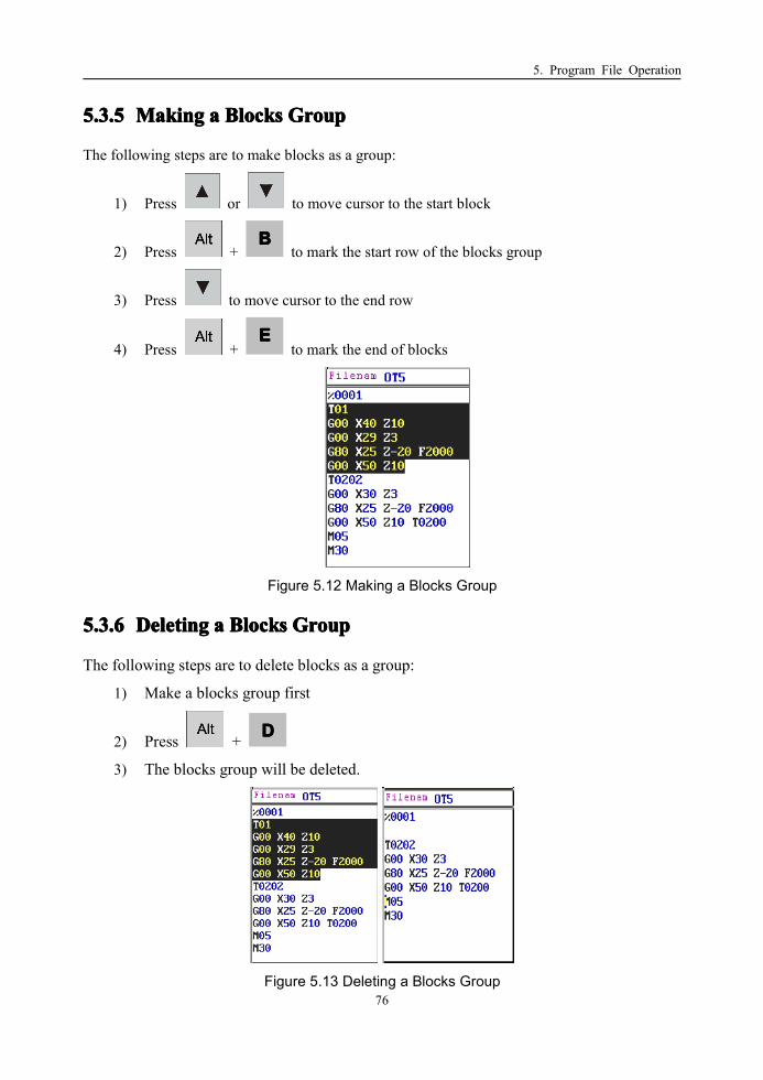
5. Program File Operation
76
5.3.55.3.55.3.55.3.5 MakingMakingMakingMaking aaaa BlocksBlocksBlocksBlocks GroupGroupGroupGroup
The following steps are to make blocks as a group:
1) Press or to move cursor to the start block
2) Press +BBBB
to mark the start row of the blocks group
3) Press to move cursor to the end row
4) Press +EEEE
to mark the end of blocks
Figure 5.12 Making a Blocks Group
5.3.65.3.65.3.65.3.6 DeletingDeletingDeletingDeleting aaaa BlocksBlocksBlocksBlocks GroupGroupGroupGroup
The following steps are to delete blocks as a group:
1) Make a blocks group first
2) Press + DDDD
3) The blocks group will be deleted.
Figure 5.13 Deleting a Blocks Group

5. Program File Operation
77
5.3.75.3.75.3.75.3.7 CuttingCuttingCuttingCutting aaaa BlocksBlocksBlocksBlocks GroupGroupGroupGroup
The following steps are to cut blocks as a group:
1) Make a blocks group first
2) Press +XXXX
. The blocks group will be cut. Different from the deleting
operation, the blocks group will be saved in clipboard when the cutting operation
is used.
Figure 5.14 Cutting a Blocks Group
5.3.85.3.85.3.85.3.8 CopyingCopyingCopyingCopying aaaa BlocksBlocksBlocksBlocks GroupGroupGroupGroup
The following steps are to copy blocks as a group:
1) Make a blocks group first
2) Press +CCCC
3) The blocks group will be copied to the clipboard.
Figure 5.15 Copying a Blocks Group

5. Program File Operation
78
5.3.95.3.95.3.95.3.9 PastingPastingPastingPasting aaaa BlocksBlocksBlocksBlocks GroupGroupGroupGroup
The following steps are to paste blocks as a group:
1) Move the cursor to position you want to settle.
2) Press +VVVV
3) The blocks group you have copied or cut to the clipboard before will be pasted
here.
Figure 5.16 Pasting a Blocks Group

5. Program File Operation
79
5.3.105.3.105.3.105.3.10FindingFindingFindingFinding aaaa StringStringStringString
The following steps are to find a string:
1) Select EditEditEditEdit mode
2) Press +FFFF
3) Input the string
Figure 5.17 Finding a String
4) Press
Note:Note:Note:Note:
1.1.1.1. If the string to find is in the current program, the cursor will stop at front of the first
string. At the same time, the color of the string and its background will be changed;
otherwise, there would be a prompt:
Figure 5.18 Finding a String – a Prompt
2.2.2.2. Press +LLLL
to find the next string.
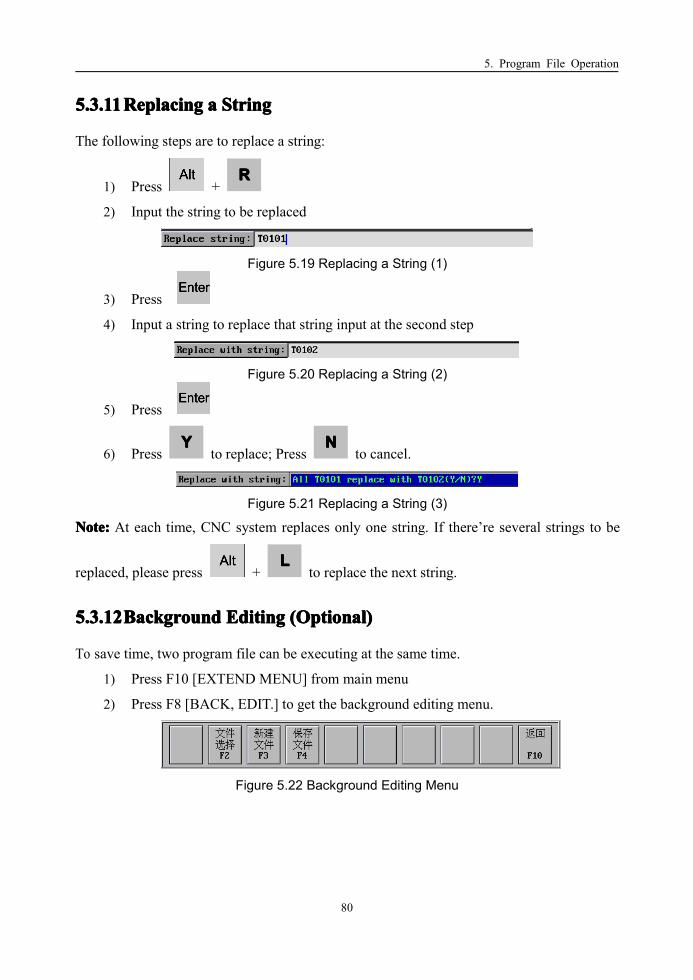
5. Program File Operation
80
5.3.115.3.115.3.115.3.11ReplacingReplacingReplacingReplacing aaaa StringStringStringString
The following steps are to replace a string:
1) Press +RRRR
2) Input the string to be replaced
Figure 5.19 Replacing a String (1)
3) Press
4) Input a string to replace that string input at the second step
Figure 5.20 Replacing a String (2)
5) Press
6) PressYYYY
to replace; PressNNNN
to cancel.
Figure 5.21 Replacing a String (3)
Note:Note:Note:Note: At each time, CNC system replaces only one string. If there’re several strings to be
replaced, please press +LLLL
to replace the next string.
5.3.125.3.125.3.125.3.12BackgroundBackgroundBackgroundBackground EditingEditingEditingEditing (Optional)(Optional)(Optional)(Optional)
To save time, two program file can be executing at the same time.
1) Press F10 [EXTEND MENU] from main menu
2) Press F8 [BACK, EDIT.] to get the background editing menu.
Figure 5.22 Background Editing Menu

5. Program File Operation
81
5.45.45.45.4 SavingSavingSavingSaving aaaa ProgramProgramProgramProgram FileFileFileFileThe following steps are to save a program file:
1) From file operation menu, press F4[Save]. Or from file edit menu, press F4[Save].
Figure 5.23 Saving a Program File
2) Type a new file name or keep the file name to save.
3) Confirm the name by “Enter”
Note:Note:Note:Note: If you want to cancel any of the above operation, just press “ESC”.

5. Program File Operation
82
5.55.55.55.5 DeletingDeletingDeletingDeleting anananan existingexistingexistingexisting ProgramProgramProgramProgram FileFileFileFileThe following steps are to delete an existing program file:
1) From file operation menu, press F1[Open].
Figure 5.24 Deleting an existing Program File (1)
2) Select the file you want to delete from the list with .
Figure 5.25 Deleting an existing Program File (2)
3) Press “Del” key on the NC keyboard area.
4) Type “Y” to confirm the operation. The file will be deleted from the media.
Figure 5.26 Deleting an existing Program File (3)

5. Program File Operation
83
5.65.65.65.6 ChangingChangingChangingChanging aaaa ProgramProgramProgramProgram FileFileFileFile NameNameNameNameChanging a program file name is a combination of “Save as” and “Delete” operation. The
following steps are to change a program file name:
1) From file operation menu, press F1[Open]. Select the file you want to change its
name from the list with .
2) Press “Enter” to open the file.
3) Press F4[Save]
4) Type the new name for the file.
5) Press “Enter” to confirm the new name.
6) Press F1[Open] to navigate the file list. Select the file with the old name from the
list with .
7) Press “Del” key.
8) Type “Y” to confirm the operation. The file will be deleted from the media.
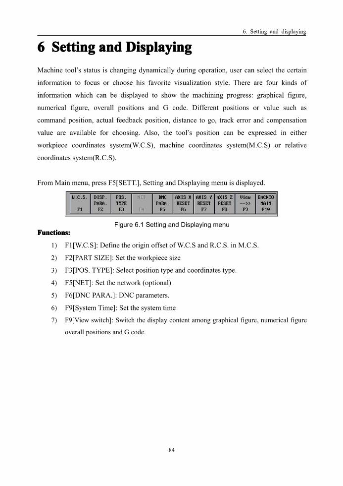
6. Setting and displaying
84
6666 SettingSettingSettingSetting andandandand DisplayingDisplayingDisplayingDisplayingMachine tool’s status is changing dynamically during operation, user can select the certain
information to focus or choose his favorite visualization style. There are four kinds of
information which can be displayed to show the machining progress: graphical figure,
numerical figure, overall positions and G code. Different positions or value such as
command position, actual feedback position, distance to go, track error and compensation
value are available for choosing. Also, the tool’s position can be expressed in either
workpiece coordinates system(W.C.S), machine coordinates system(M.C.S) or relative
coordinates system(R.C.S).
From Main menu, press F5[SETT.], Setting and Displaying menu is displayed.
Figure 6.1 Setting and Displaying menuFunctions:Functions:Functions:Functions:
1) F1[W.C.S]: Define the origin offset of W.C.S and R.C.S. in M.C.S.
2) F2[PART SIZE]: Set the workpiece size
3) F3[POS. TYPE]: Select position type and coordinates type.
4) F5[NET]: Set the network (optional)
5) F6[DNC PARA.]: DNC parameters.
6) F9[System Time]: Set the system time
7) F9[View switch]: Switch the display content among graphical figure, numerical figure
overall positions and G code.
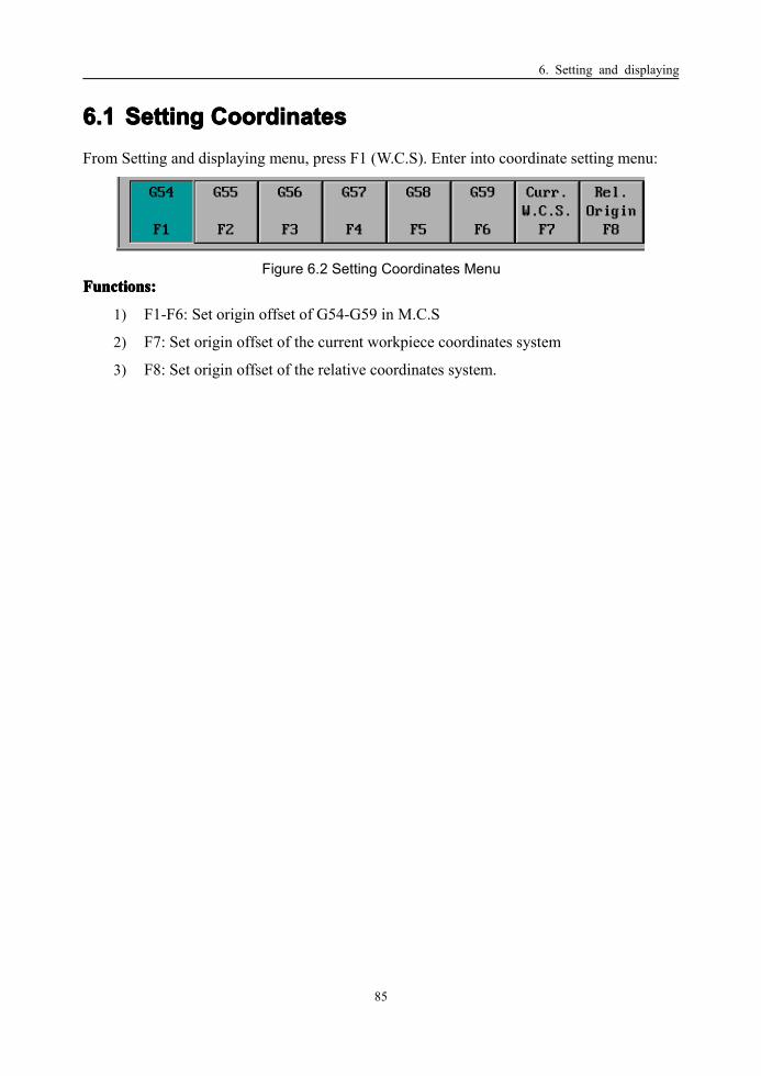
6. Setting and displaying
85
6.16.16.16.1 SettingSettingSettingSetting CoordinatesCoordinatesCoordinatesCoordinatesFrom Setting and displaying menu, press F1 (W.C.S). Enter into coordinate setting menu:
Figure 6.2 Setting Coordinates MenuFunctions:Functions:Functions:Functions:
1) F1-F6: Set origin offset of G54-G59 in M.C.S
2) F7: Set origin offset of the current workpiece coordinates system
3) F8: Set origin offset of the relative coordinates system.

6. Setting and displaying
86
6.26.26.26.2 WorkpieceWorkpieceWorkpieceWorkpiece SizeSizeSizeSizeTo display the graphic figure in the viewpoint, viewpoint parameters should be set correctly.
In Setting and displaying menu, F2[DISP. PARA] is for setting the viewpoint parameters.
Three groups of parameters are needed to set the viewpoint step by step.
1) Coordinate(x, y, z): Offset of the displaying coordinates origin.
Figure 6.3 Workpiece Size - Coordinate
2) Zoom In(x, y, z): Scale factor in x, y and z direction.
Figure 6.4 Workpiece Size – Zoom In
3) Angle(x, y, z): Parameters that used to change the view angle about x, y and z axis.
Figure 6.5 Workpiece Size - Angle

6. Setting and displaying
87
6.36.36.36.3 PositionPositionPositionPosition andandandand CoordinateCoordinateCoordinateCoordinate ChoiceChoiceChoiceChoiceFrom Setting and displaying menu, press F3[POS.TYPE] to choose the position and
coordinates type.
Figure 6.6 Position and Coordinate Choice
The procedure for setting the position and coordinate type:
1) Use or to switch between position radios and coordinates radios.
2) Use or to select different position or coordinates type.
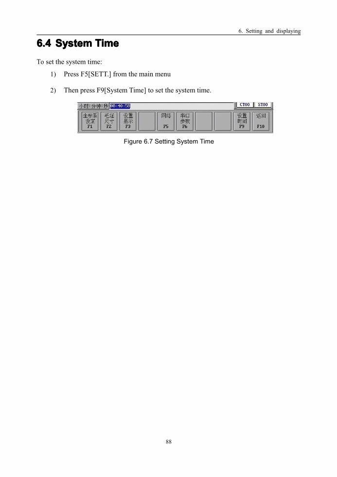
6. Setting and displaying
88
6.46.46.46.4 SystemSystemSystemSystem TimeTimeTimeTimeTo set the system time:
1) Press F5[SETT.] from the main menu
2) Then press F9[System Time] to set the system time.
Figure 6.7 Setting System Time

6. Setting and displaying
89
6.56.56.56.5 ViewViewViewView SwitchSwitchSwitchSwitchFour kinds of information contents are available for choosing to be displayed in the center
of LCD screen. They are graphical figure, numerical figure, overall positions and G code.
Press F9 (View) to switch among these four options. These four kinds of displaying status
will be switched from one to another by pressing F9.
���� GraphicGraphicGraphicGraphic ViewViewViewView
Figure 6.8 Graphic View
���� NumericalNumericalNumericalNumerical ViewViewViewView
Figure 6.9 Numerical View

6. Setting and displaying
90
���� OverallOverallOverallOverall PPPPositionsositionsositionsositions ViewViewViewView
Figure 6.10 Overall Position View
���� GGGG codecodecodecode ViewViewViewView
Figure 6.11 G code View

7. Network Services
91
7777 NetworkNetworkNetworkNetwork ServicesServicesServicesServices (Optional)(Optional)(Optional)(Optional)
7.17.17.17.1 EthernetEthernetEthernetEthernet ConnectionConnectionConnectionConnectionThe procedures for the Ethernet connection is as follows:
1) Connect the Ethernet cables to the HUB
2) Connect the Ethernet cable to the Ethernet interface on CNC machine.
3) Turn the power on to check the connection. It is connected if the indicator light on
the Ethernet interface is on. Otherwise, it is not connected.
4) Install the Network Services of HNC NetDnc (v1.0).

7. Network Services
92
7.27.27.27.2 NetworkNetworkNetworkNetwork ConnectionConnectionConnectionConnectionThe procedure for the network connection is:
1) Press F5[SETT.] from the main menu
2) Then press F5[NET] to get the network connection menu
Figure 7.1 Network Connection Menu
3) Set the server IP address. This step can be skipped if the server IP address has been
set at last time.
Figure 7.2 Setting the server IP address
4) Press F1 to connect the network.
� If it is connected, the screen would be as follows:
Figure 7.3 Successful Connection

7. Network Services
93
� If it can not be connected, the screen would be as follows:
Figure 7.4 Failed Connection
5) Use to reset the server IP address or the client IP
address if it is necessary.
Figure 7.5 Resetting the server IP address

7. Network Services
94
Figure 7.6 Resetting the client IP address
6) If the connection is failed, there will be black screen. And then the system is
returned to the initial status.
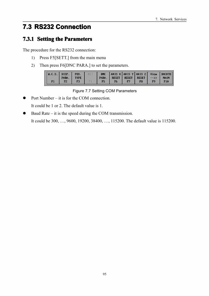
7. Network Services
95
7.37.37.37.3 RS232RS232RS232RS232 ConnectionConnectionConnectionConnection
7.3.17.3.17.3.17.3.1 SettingSettingSettingSetting thethethethe ParametersParametersParametersParameters
The procedure for the RS232 connection:
1) Press F5[SETT.] from the main menu
2) Then press F6[DNC PARA.] to set the parameters.
Figure 7.7 Setting COM Parameters
� Port Number – it is for the COM connection.
It could be 1 or 2. The default value is 1.
� Baud Rate – it is the speed during the COM transmission.
It could be 300, …, 9600, 19200, 38400, …, 115200. The default value is 115200.

7. Network Services
96
7.3.27.3.27.3.27.3.2 SettingSettingSettingSetting UpUpUpUp thethethethe ConnectionConnectionConnectionConnection
The procedure for setting up the connection is as follows:
1) Press F7[DNC] from the main menu
Figure 7.8 DNC
2) Press “Y” or “Enter” to get the DNC mode.
Figure 7.9 DNC Mode
3) Depending on the command from the client, three main services can be offered:
� Get/Receive G code
� Get/Receive the parameters of CNC system
� Get/Receive CNC PLC
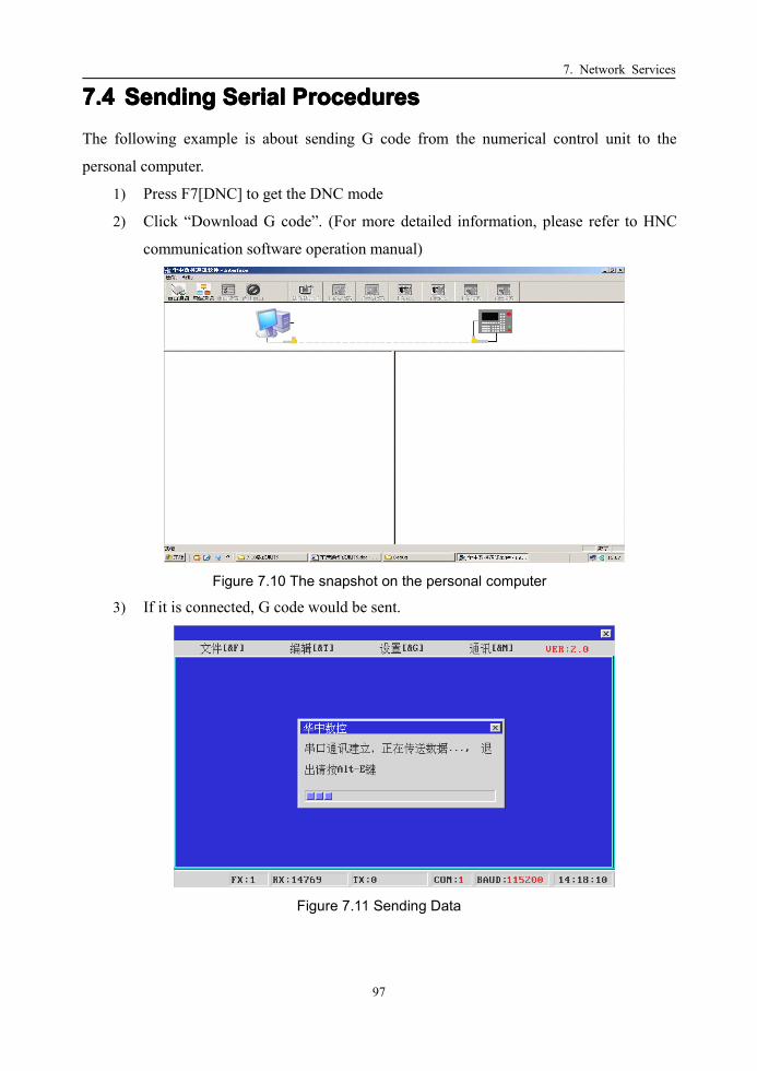
7. Network Services
97
7.47.47.47.4 SendingSendingSendingSending SerialSerialSerialSerial ProceduresProceduresProceduresProceduresThe following example is about sending G code from the numerical control unit to the
personal computer.
1) Press F7[DNC] to get the DNC mode
2) Click “Download G code”. (For more detailed information, please refer to HNC
communication software operation manual)
Figure 7.10 The snapshot on the personal computer
3) If it is connected, G code would be sent.
Figure 7.11 Sending Data

7. Network Services
98
7.57.57.57.5 ReceivingReceivingReceivingReceiving SerialSerialSerialSerial ProceduresProceduresProceduresProceduresThe following example is about receiving G code from the personal computer.
1) Press F7[DNC] to get the DNC mode
2) Click “Send G code”. (For more detailed information, please refer to HNC
communication software operation manual v1.0)
3) If it is connected, G code would be sent.
Figure 7.12 Receiving Data
4) When it is done, the following figure would be shown.
Figure 7.13 Data is finished receiving

8. Diagnosis
99
8888 DiagnosisDiagnosisDiagnosisDiagnosisWhen a fault occurs, the CNC system will give an alarm message. User can read these
message to analyze the reason of the fault.
From Main menu, press F6[DIAGNOSIS], enter into diagnosis menu.
Figure 8.1 Diagnosis MenuFunctions:Functions:Functions:Functions:
1) F6[Alarm list]: Display the current alarm message.
Figure 8.2 Alarm List
2) F7[Alarm record]: Display all the alarm information occurred before.
Figure 8.3 Alarm Record

9. PLC Function
100
9999 PLCPLCPLCPLC FunctionFunctionFunctionFunctionFrom Main Menu, press F10[EXTEND MENU]. Press F1[PLC] to enter into PLC
functions.
Figure 9.1 PLC function
FunctionsFunctionsFunctionsFunctions:
1) F1: Load a PLC program
2) F2: Modify a PLC program
3) F3: I/O status
4) F4::::Watch all registers value.
5) F7: Backup a PLC program

9. PLC Function
101
9.19.19.19.1 F3:F3:F3:F3: I/OI/OI/OI/O StatusStatusStatusStatusThis function enables the user to check the I/O status. Status of Input points from machine
to PMC (X register) and output points from PMC to machine (Y register) can be monitored
in this window.
Figure 9.2 I/O Status
“On” indicates the I/O points is on.
“Off” indicates the I/O points is off.

9. PLC Function
102
9.29.29.29.2 F4:F4:F4:F4: WatchWatchWatchWatchThe status of all registers can be monitored with this function. When F4 (Watch) is pressed,
a window as following will pop up. As it is shown in the figure, there are seven registers:
1) X: PMC�Machine
2) Y: Machine�PMC
3) F: CNC�PMC
4) G: PMC�CNC
5) R: Intermediate register in PMC
6) P: Parameters
7) B: Buffer to store system status information in case of unexpected power-off
Figure 9.3 PLC Register

9. PLC Function
103
The procedure is as follows:
1) Use or to select a register from the above list. Press Enter to confirm
the selection.
2) For example, if we want to monitor the current values of G register, we can press F4.
The values of all G registers will be displayed:
Figure 9.4 Monitoring Register
3) Then there are three kinds of digital forms to display the value
� F5[BIN]: display the register value in binary
� F6[DEC]: display the register value in decimal
� F7[HEX]: display the register value in hex
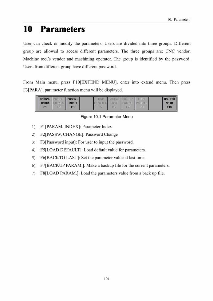
10. Parameters
104
10101010 ParametersParametersParametersParametersUser can check or modify the parameters. Users are divided into three groups. Different
group are allowed to access different parameters. The three groups are: CNC vendor,
Machine tool’s vendor and machining operator. The group is identified by the password.
Users from different group have different password.
From Main menu, press F10[EXTEND MENU], enter into extend menu. Then press
F3[PARA], parameter function menu will be displayed.
Figure 10.1 Parameter Menu
1) F1[PARAM. INDEX]: Parameter Index
2) F2[PASSW. CHANGE]: Password Change
3) F3[Password input]: For user to input the password.
4) F5[LOAD DEFAULT]: Load default value for parameters.
5) F6[BACKTO LAST]: Set the parameter value at last time.
6) F7[BACKUP PARAM.]: Make a backup file for the current parameters.
7) F8[LOAD PARAM.]: Load the parameters value from a back up file.

10. Parameters
105
10.110.110.110.1 F1:F1:F1:F1: ParameterParameterParameterParameter IndexIndexIndexIndexThere are different sorts of parameters. User can choose the specified sort of parameters to
check or modify from this index. For the CNC’s vendor and the machine tool’s vendor,
password should be provided first to access parameters belonged to his own authority.
A parameter list would pop up when press F1 [PARAM. INDEX]:
Figure 10.2 Parameter List
1) F1: Machine parameters
2) F2: Axis parameters
3) F3: Servo parameters
4) F4: Compensation parameters
5) F5: PMC user parameters

10. Parameters
106
10.1.110.1.110.1.110.1.1MachineMachineMachineMachine ParametersParametersParametersParameters
Turret direction(0/1)
0: positive direction of X axes in graphic display is downward.
1: positive direction of X axes in graphic display is upward.
Diameter/Radius at X(1/0)
0: dimension along X axes is given as radius
1: dimension along X axes is given as diameter
Metric/Inches(1/0)
0: unit of dimension is thousandth of an inch
1: unit of dimension is thousandth of a mini-meter
Power-off protection(1/0)
0: data protection in case of power off is disabled
1: data protection in case of power off is enabled
Tool Comp. Type(0:Abs. 1:Rel.)
0: compensate the tool nose radius in absolute coordinates
1: compensate the tool nose radius relative to standard tool
Pulse type(0:uni-dir,1:bi-dir,2:AB)
0: pulse is uni-direction
1: pulse is bi-direction
2: pulse is AB phase
Spindle encoder direction(32:+,33:-)
32: direction of encoder on spindle is positive
33: direction of encoder on spindle is negative
Spindle encoder part number
Part number of the spindle encoder.
10. Parameters
107
10.1.210.1.210.1.210.1.2AxisAxisAxisAxis ParametersParametersParametersParameters
Pulse/um(um)
Movement distance of the axis per revolution of the motor. The unit is um for linear
axis, a thousandth of 1° for rotational axis.
Pulse/um(pulse)
Encode counter per revolution of the motor.
Note: this two numbers can be commonly divided into prime numbers.
Software limits positive(um)
Positive position of this axis’s software limit in M.C.S
Software limits negative(um)
Negative position of this axis’s software limit in M.C.S
Reference approach mode(1:+-,2:+-)
Method to approach the reference point of this axis.
1: Move forward to find the encoder’s zero position after the reference switch
is reached.
2: Moving backward to find the encoder’s zero position after the reference
switch is reached,
Reference approach direction(“+”, “-”)
Rapid traverse direction during reference point approaching.
+: positive direction. Use this option if the tool is at the minus side of the
reference switch
-: negative direction. Use this option if the tool is at the negative side of the
reference switch
Reference point position(um)
Coordinates value of the reference point in the M.C.S

10. Parameters
108
Reference point offset(um)
Offset distance after the encoder’s zero position is found.
Rapid traverse speed for reference approach
Speed before the reference switch is reached.
Slow speed for reference approach(mm/m)
Speed used to find the encoder’s zero position after the reference switch is reached.
Deceleration distance for G60
Distance between the deceleration point and the command position while G60 is used
to do uni-direction position.
Rapid traverse rate(mm/min)
Speed for rapid traverse. G00 use this speed.
Maximum feedrate(mm/min)
Maximum feed rate for this axis.
Acc. time constant for rapid traverse(mm/min)
Acceleration time to get a speed increase of 1000mm/min during rapid traverse motion.
Jerk time constant for rapid traverse(ms)
Jerk time to get an acceleration increase of 1000mm/sec during rapid traverse motion
Acc. time constant for feeding(mm/min)
Acceleration time to get a speed increase of 1000mm/min during machining feeding.
Jerk time constant for feeding(ms)
Jerk time to get an acceleration increase of 1000mm/sec during machining feeding.
Track tolerance: Maximum tracking error.

10. Parameters
109
10.1.310.1.310.1.310.1.3ServoServoServoServo ParametersParametersParametersParameters
Feedback to NC(45:YES,46:NO)
45: Encoder counter feedback to NC. This is always true if servo driver is used.
46: No encoder or no position feedback to NC. This is always true if step motor is used.
Servo part number.
Part number of the servo driver. Value is from –1~31. –1 means none and zero is the
first one.
Position loop gain(open-loop)
Gain coefficient of the position loop. For open loop control. The bigger this value, the
better rigidity the system can reach. But if the value is too high, the system may become
unstable and vibration may occur. The value ranges from 1~10000. The unit is 0.01sec-1.
Default value is 3000.
Position loop feedforward coefficient(kf)
The value ranges from 0~65535. Default value is 0.
Velocity loop proportion coefficient(kp)
Ranges from 0~65535. Default value is 2000. 3000~7000 is recommended.
Velocity loop integral(ki)
Ranges from 0~65535. Default value is 100. 20~50 is recommended.
Maximum torque
Ranges from 0~255. Default value is 150. Only effective for HSV-11.
Rated torque
Ranges from 0~255. Default value is 100. Only effective for HSV-11.

10. Parameters
110
Tracking error
Tracking error threshold. Alarm will be displayed if the actual tracking supersede this
value.
Pulse per revolution
Pulse counter value the NC get per revolution of the motor.
10.1.410.1.410.1.410.1.4CompensationCompensationCompensationCompensation ParametersParametersParametersParameters
Backlash(um)
This value should be calibrated by measurement instrument. The unit is 0.001mm. It
should be set as 0 if bi-directional pitch compensation is used.
Pitch err. comp. type(1:uni-dir,2:bi-dir)
Pitch error compensation type.
1: Compensate the pitch error in uni-direction.
2: Compensation the pitch error in bi-directions.
Compensation points number:
Range from 0~127. Can be extended to 5000.
The maximum measure point is 128 if uni-direction compensation type is used.
The maximum measure point is 64 if bi-direction compensation type is used.
Index of reference point.
Index of the compensation point in the compensation table.
Compensation gap
Distance between two adjacent compensation points.

10. Parameters
111
10.1.510.1.510.1.510.1.5PMCPMCPMCPMCUserUserUserUser ParametersParametersParametersParameters

10. Parameters
112
10.210.210.210.2 F2:F2:F2:F2: PasswordPasswordPasswordPassword ChangeChangeChangeChangeThis function is to change a password. This function is only enabled when the user enter his
password.
The following steps are to change a password:
1) Enter the old password first.
Figure 10.3 Inputting an old password
2) Enter the new password.
Figure 10.4 Inputting a new password

10. Parameters
113
10.310.310.310.3 F3:F3:F3:F3: PasswordPasswordPasswordPassword InputInputInputInputThis function is to input the password.
Figure 10.5 Inputting the password
10.410.410.410.4 F5:F5:F5:F5: LoadLoadLoadLoad DefaultDefaultDefaultDefaultThis function is to set the parameters as the default value.
10.510.510.510.5 F6:F6:F6:F6: BackBackBackBack totototo LastLastLastLastThis function is to set the parameter values at last time.

10. Parameters
114
10.610.610.610.6 F7F7F7F7:::: BackupBackupBackupBackupThis function is to make a backup file for the current parameters.
1) Press “Y” if you want to backup the current parameters
Figure 10.6 Backup the parameter values
2) Type the backup file name.
Figure 10.7 Typing a backup file name
3) Press “Enter”, the current file will be backup in the file.

10. Parameters
115
10.710.710.710.7 F8:F8:F8:F8: LoadLoadLoadLoadThis function is to load the parameters value from a back up file.
1) Use or to select the backup file source among CF, DNC or Floppy
disk.
Figure 10.8 Backup file List
2) Use or to select the backup file from the file list.
3) Press “Enter” to confirm.
Figure 10.9 Confirming to load a backup file