central electricity supply utility of odisha203.193.144.25/ced06/railway_bid_document.pdfdeposit...
TRANSCRIPT

DEPOSIT CED, CUTTACK BID DOCUMENT 2017-18
Page 1 of 138
CENTRAL ELECTRICITY SUPPLY UTILITY OF ODISHA
BID DOCUMENT
Tender Specification No –
CESU-CED /DEPOSIT-TURNKEY/02/2017-18
FOR
SHIFTING AND RE-LOCATION OF 11 KV LINES AND SUB-STATION
WITH UP-GRADATION OF S/S AND CONSTRUCTION OF LT LINE
UNDER TURNKEY CONTRACTS.
(SUPPLY & ERECTION)
(UNDER 100% DEPOSIT WORK ON PARTLY TURNKEY BASIS )

DEPOSIT CED, CUTTACK BID DOCUMENT 2017-18
Page 2 of 138
CENTRAL ELECTRICITY SUPPLY UTILITY OF ORISSA
(Formerly CESCO) Registered Office : IDCO TOWERS, (IInd Floor), Janapath, Bhubaneswar – 751 022
OFFICE OF THE EXECUTIVE ENGINEER(ELECT.), CUTTACK ELECTRICAL DIVISION, CUTTACK
E mail:- [email protected], : 0671-2414052, 9437011317, Fax : 0671 – 2414278
TENDER CALL NOTICE NO. 02 / 2017-18
Tender Specification No : CESU-CED/DEPOSIT-Turnkey/02/2017-18
CONTENTS
Sl. No. Particulars Page No. Remarks
1 Tender Notice 3-5
2 Section-I, General Conditions of Contract (GCC) 6-24
3 Section-II, Information to Bidders (IFB) 24-32
4 Section-III, Technical Specification 33-80
5 Drawings 81-92
6 Annexure & Bid Proposal Sheets 93
7a Schedule of Quantity 94
7b Price Schedule format 95-115
7c BG Proforma for EMD 116-117
7d BG Proforma Contract Performance Guarantee 118-120
7e Bid Proposal Letter 121-125
7f Declaration form 126
7g Qualifying Requirements 127
7h Commercial deviation 128
7i Technical deviation 129
7j Additional Information 130
7k Bought out & Sub-Contract Items 131
7l Work Completion Schedule 132
7n Check List 133-134
7o Self declaration 135
DEPOSIT CED, CUTTACK BID DOCUMENT 2017-18
Page 3 of 138
TENDER CALL NOTICE
CENTRAL ELECTRICITY SUPPLY UTILITY OF ORISSA (Formerly CESCO)
Registered Office : IDCO TOWERS, (IInd Floor), Janapath, Bhubaneswar – 751 022
OFFICE OF THE EXECUTIVE ENGINEER(ELECT.), CUTTACK ELECTRICAL DIVISION, CUTTACK
E mail:- [email protected], : 0671-2414052, 9437011317, Fax : 0671 – 2414278
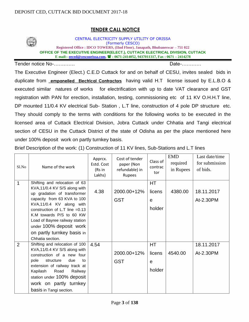
Tender notice No-…………. Date-…………
The Executive Engineer (Elect.) C.E.D Cuttack for and on behalf of CESU, invites sealed bids in
duplicate from empanelled Electrical Contractors having valid H.T license issued by E.L.B.O &
executed similar natures of works for electrification with up to date VAT clearance and GST
registration with PAN for erection, installation, testing, commissioning etc of 11 KV O.H.H.T line,
DP mounted 11/0.4 KV electrical Sub- Station , L.T line, construction of 4 pole DP structure etc.
They should comply to the terms with conditions for the following works to be executed in the
licensed area of Cuttack Electrical Division, Jobra Cuttack under Chhatia and Tangi electrical
section of CESU in the Cuttack District of the state of Odisha as per the place mentioned here
under 100% deposit work on partly turnkey basis.
Brief Description of the work: (1) Construction of 11 KV lines, Sub-Stations and L.T lines
Sl.No Name of the work
Apprcx. Estd. Cost
(Rs in Lakhs)
Cost of tender paper (Non
refundable) in Rupees
Class of contrac
tor
EMD
required
in Rupees
Last date/time
for submission
of bids.
1 Shifting and relocation of 63
KVA,11/0.4 KV S/S along with
up gradation of transformer
capacity from 63 KVA to 100
KVA,11/0.4 KV along with
construction of L.T line =0.13
K.M towards P/S to 60 KW
Load of Bayree railway station
under 100% deposit work
on partly turnkey basis in
Chhatia section.
4.38
2000.00+12%
GST
HT
licens
e
holder
4380.00
18.11.2017
At-2.30PM
2 Shifting and relocation of 100
KVA,11/0.4 KV S/S along with
construction of a new four
pole structure due to
extension of railway track at
Kapilash Road Railway
station under 100% deposit
work on partly turnkey
basis in Tangi section.
4.54
2000.00+12%
GST
HT
licens
e
holder
4540.00
18.11.2017
At-2.30PM

DEPOSIT CED, CUTTACK BID DOCUMENT 2017-18
Page 4 of 138
3 Shifting and relocation of 100
KVA,11/0.4 KV S/S along with
construction of a new four
pole structure due to
extension of railway track at
Charbatia Railway station
under 100% deposit work
on partly turnkey basis in
Tangi section.
4.63
2000.00+12%
GST
HT
licens
e
holder
4630.00
18.11.2017
At-2.30PM
TERMS AND CONDITION –
1. Further details(if required) can be had from the office of the undersigned during office hours. The work
put to tender will be executed depending on the availability of fund
2. EMD in shape of NSC/post office saving pass book/Cash/Bank draft in any Nationalized Bank/post
office duly pledged in favors of “CESU C.E.D Cuttack” should be given with tender as mentioned against
the work. The offers without valid EMD/Part EMD will be out rightly rejected.
1. The sale of bid documents will be available for sale in the office of the undersigned from dated
13.11.2017 To 18.11.2017 during office working hours and up to 2:00 P.M on date- 18.11.2017 on
payment of cost of tender paper (Non refundable). The complete bid documents will be received up
to 2:30 P.M on date 18.11.2017. in the office of the undersigned and will be opened on date
18.11.2017 at 4.00 P.M at C.E.D Jobra Cuttack . Participants or their authorized agents may remain
present during opening of tender.
2. Eligibility criteria :
a) The intending bidders should show up-to-date valid HT contractors Registration certificate, PAN
card, GST registration certificate etc.
b) The following documents, certificates should be furnished along with tender papers failing which
the tender is liable for rejection.
i. The bidder should submit the EMD rounded to nearest next hundred rupees.
ii. The bidder Quoting for more than one work is required to submit the bid documents
separately i.e one envelope for each work with individual EMD. Deposit of EMD in
consolidated manner is liable for rejection.
iii. Attested copy of contractor registration/ licensed / labour license certificate
iv. Attested copy of valid pan card, GST registration certificate
c) All documents should be produced in very clear and legible manner duly self attested and free
from any ambiguity and all documents should be signed by the agency as per specimen signature
in the license copy. In case of any deviation the tender will be liable for rejection.
d) The completed documents can be dispatched by Regd. Post/ speed post to the undersigned
which should reach on or before schedule date and time of receipt of tender. The department will
DEPOSIT CED, CUTTACK BID DOCUMENT 2017-18
Page 5 of 138
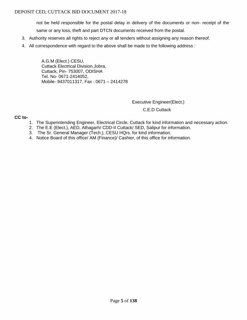
not be held responsible for the postal delay in delivery of the documents or non- receipt of the
same or any loss, theft and part DTCN documents received from the postal.
3. Authority reserves all rights to reject any or all tenders without assigning any reason thereof.
4. All correspondence with regard to the above shall be made to the following address :
A.G.M (Elect.) CESU, Cuttack Electrical Division,Jobra, Cuttack, Pin- 753007, ODISHA Tel. No- 0671-2414052, Mobile- 9437011317, Fax : 0671 – 2414278
Executive Engineer(Elect.)
C.E.D Cuttack
CC to- 1. The Superintending Engineer, Electrical Circle, Cuttack for kind information and necessary action. 2. The E.E (Elect.), AED, Athagarh/ CDD-II Cuttack/ SED, Salipur for information. 3. The Sr. General Manager (Tech.), CESU HQrs. for kind information. 4. Notice Board of this office/ AM (Finance)/ Cashier, of this office for information.

DEPOSIT CED, CUTTACK BID DOCUMENT 2017-18
Page 6 of 138
SECTION – I
GENERAL CONDITIONS OF CONTRACT (GCC)
Tender Specification No : CESU-CED/DESI-TURNKEY/02/2017-18

DEPOSIT CED, CUTTACK BID DOCUMENT 2017-18
Page 7 of 138
1.0 GENERAL: -
Executive Engineer, Cuttack Electrical Division, Cuttack , hereinafter referred to as
the “Owner” are desirous of shifting and relocation of 11 KV line with up gradation of
S/S, construction of four pole DP structure etc. and construction of LT line and System
Improvement Works due to extension of railway track at Kapilash road, Charbatia
and Byree railway station on ‘ Partial turnkey’ basis in Tangi and Chhatia section
under C.E.D Cuttack, pertaining to Tangi Choudwar/Badachana of Cuttack /Jajpur
district in the state of Odisha as described below :
(i) Shifting and relocation of 11 KV line and S/S
(ii) Construction of 4 pole DP structure.
(iii) Construction of L.T line
a) Scope of Work: -
2.1 The scope shall include supply and installation of all materials & equipments to
complete the works except the materials/ equipments which shall be supplied by
the CESU (OSM Materials) and describe as Annexure-1,2 and 3.
N.B: While executing the works, if the OSM Materials are not available at CESU store
(except sl. No a & g), then these materials may be treated as CSM.
2.2 The detailed scope of the work shall include;
i. Detailed survey of substation, line and preparation of SLD / BOQ to be done by
the bidder.
ii. Complete manufacture, supply of materials from the approved vendor (materials
which are to be supplied by the bidder) on subsequent approval of the owner.
iii. Providing Engineering drawing, data, operational manual, etc for the Owner’s
approval;
iv. Packing and transportation from the manufacturer’s works to the site.
v. Receipt, storage, preservation and conservation of equipment at the site.
vi. Pre-assembly, if any, erection testing and commissioning of all the equipment;
vii. Reliability tests and performance and guarantee tests on completion of
commissioning;
viii. Loading, unloading and transportation as required.
ix. Erection of equipments in Sub-station including civil works.
x. Erection of lines of specified voltage.
xi. Testing, Commissioning of substations and lines / installations
xii. Storing before erection

DEPOSIT CED, CUTTACK BID DOCUMENT 2017-18
Page 8 of 138
xiii. Getting the substations & lines inspected by Appropriate authority after
completion of work.
xv. Dismantling of existing electrical structures and return of these dismantled items at
the Owner’s stores, safe custody of the items.
3.00 DEFINITION OF TERMS
In construing this contract and the scope of work, the following words will have same
meaning herein assigned to them unless there is something in the subject or context in
context in consistent with such construction.
3.01 Owner / Purchaser:
The “Owner / Purchaser” shall mean the Executive Engineer, CED, CESU, Cuttack and
shall include its legal representative, successors and assignees.
3.02 Contractor:
The “Contractor” shall mean the firm whose tender has been accepted by the owner
and shall include its legal representatives, successors and assignees. The
bidders/contractors who have registered with MSME organization, they may get
preference as per Govt. of India rule.
3.03 Engineer In Charge:
The “Engineer In Charge” shall mean the Executive Engineer, CED, CESU, Cuttack of the
work for owner or his authorized representative.
3.04 Consignee
The “Consignee” shall mean the person authorized by the owner to receive the
materials, supervise and take measurement of the work.
3.05 Site:
The “Site” shall mean, the actual place of the proposed project as detailed in the
specification or other place where work has to be executed under this contract.
3.06 Specification:
‘Specifications’ shall mean the specifications and Bidding Document forming a
part of the Contract and such other schedules and drawings as may be
mutually agreed upon.
.
3.07 Contract:
The “Contract” shall mean and include the following documents:
a) Invitation to Tender
b) Instruction to Tender
c) General Terms of contract and Technical field requirement
DEPOSIT CED, CUTTACK BID DOCUMENT 2017-18
Page 9 of 138
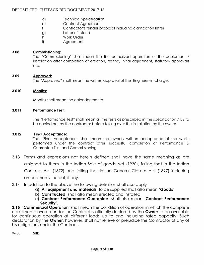
d) Technical Specification
e) Contract Agreement
f) Contractor’s tender proposal including clarification letter
g) Letter of intend
h) Work Order
i) Agreement
3.08 Commissioning:
The “Commissioning” shall mean the first authorized operation of the equipment /
installation after completion of erection, testing, initial adjustment, statutory approvals
etc.
3.09 Approved:
The “Approved” shall mean the written approval of the Engineer–in-charge.
3.010 Months:
Months shall mean the calendar month.
3.011 Performance Test:
The “Performance Test” shall mean all the tests as prescribed in the specification / ISS to
be carried out by the contractor before taking over the installation by the owner.
3.012 Final Acceptance:
The “Final Acceptance” shall mean the owners written acceptance of the works
performed under the contract after successful completion of Performance &
Guarantee Test and Commissioning.
3.13 Terms and expressions not herein defined shall have the same meaning as are
assigned to them in the Indian Sale of goods Act (1930), failing that in the Indian
Contract Act (1872) and failing that in the General Clauses Act (1897) including
amendments thereof, if any.
3.14 In addition to the above the following definition shall also apply
a) ‘All equipment and materials’ to be supplied shall also mean ‘Goods’
b) ‘Constructed’ shall also mean erected and installed. c) ‘Contract Performance Guarantee’ shall also mean ‘Contract Performance
Security’. 3.15 ‘Commercial Operation’ shall mean the condition of operation in which the complete equipment covered under the Contract is officially declared by the Owner to be available for continuous operation at different loads up to and including rated capacity. Such declaration by the Owner, however, shall not relieve or prejudice the Contractor of any of his obligations under the Contract.
04.00 SITE

DEPOSIT CED, CUTTACK BID DOCUMENT 2017-18
Page 10 of 138
04.01 The site is spread in Cuttack revenue district of Orissa state. The location, where proposed work
to be done under Tangi Choudwar/Badachana block as detailed below:
Sl. No Name of WORK Location
1
Shifting and relocation of S/S,up
gradation of s/s,11 KV line,
construction of 4 pole structure
,construction of L.T line etc.
Kapilash
Road,Charbatia
and Byree railway
station.
TOTAL
05.00 SERVICE CONDITIONS
All outdoor Equipment/material to be supplied against this specification shall be suitable for
satisfactory continuous operation under tropical conditions as specified below:
1. Maximum ambient temperature (°C) 50
2. Minimum ambient temperature (°C) 0
3. Relative humidity (%) – Range 10 - 100
4. Maximum Annual rainfall (cm) 70 - 200
5. Maximum wind Pressure (Kg/m2.) 75
6. Moderately hot and humid tropical, climate, Yes
conductive to rust and fungus growth
06.00 BID DOCUMENTS
06.01 The bid specification documents are available in the office of the Executive Engineer, CED,
Cuttack for sale to the interested eligible parties on receipt of application for the same
alongwith a Bank Demand Draft drawn in favour of the Executive Engineer, CED, Cuttack at
Cuttack for an amount of Rs.2, 000.00 + 18% GST for each work.
06.02 The bid specification documents will be available for sale on submission of a written application
from Dt. 13.11.2017 during office working hours. Completed bids shall be received upto 14.30 Hrs.
on Dt. 18.11.2017. The bid will be opened on date-18.11.2017 at 16.00 Hr in the Office of the
owner.
06.03 Bids received after the due date and without E.M.D. shall be rejected outright. The undersigned
reserves the right to reject any or all bids without assigning any reasons if the situation warrants.
06.04 A complete set of bidding documents can be downloaded from our website
http:/www.cescoorissa.com. However for the bidders who has obtained the bid document by
down loading from the website must submit along with demand draft for an amount of
Rs.2,000.00+18% GST for each work in order to make them eligible to participate in the
tender.
06.05 Request for Bid Document through post will not be entertained.
06.06 The Bids will be opened in presence of Bidders / Bidder’s representatives as per
Guidelines.
06.07 Bids without E.M. Deposit will be rejected outright. No adjustment of any previous
deposit will be entertained. The E.M. Deposit shall be forfeited in case of withdrawal of
bids after the last date of submission and / or non-acceptance of order.
07.00 SUBMISSION OF TENDER:
07.01

DEPOSIT CED, CUTTACK BID DOCUMENT 2017-18
Page 11 of 138
Sealed tenders in Single parts in duplicate, complete in all respects in the manner
hereinafter specified are to be submitted in the office of the Executive Engineer,
CED, Cuttack, Address on or before the date and time specified in the notice inviting
the tenders. Bids shall be submitted as per format provided in Section VI. Each copy
of the bids (original and duplicate) shall be submitted in double sealed envelopes
superscripted on the covers the tender specification number and the due date of
opening of the bids on the right hand top side of the envelop. On the left top side
original/ duplicate as is relevant shall be written.
07.02 The tenders are required to be submitted in Single Parts in double sealed covers with
following requisites.
Contain EMD, Cost of Bid Documents, Techno commercial documents & Price Bid.
07.03 Fax and Telegraphic tenders shall not be accepted. 07.04 Receipt of bids/ revised bids after the cut off time and date as specified in the
Tender specification shall not be permitted and such bids shall be rejected outright.
The Owner shall not be responsible for any delay in transit in post / courier etc. in this
regard. 07.05 VALIDITY :-
The offer shall be valid for a period not less than 45days from the date of bid opening.
08.00 Bill of Quantity of Work
The contractor will survey jointly with concerned J.E. to determine the actual scope
and BoQ before starting the work in the field and forward the actual scope with BoQ
to this office for approval.
09.00 PRICE: -
Bidders are required to quote firm price as per the prescribed format enclosed in
Section – VI. The quoted price shall be firm and inclusive of all taxes, duties, freight &
insurance and other levies, if any. Owner shall not be liable to pay anything extra
over and above the quoted price.
10.0 RECEIPT AND OPENING OF THE BID : -
10.01
Bids in duplicate as described under clause 07.00 shall be received in the office of
the Executive Engineer, CED, Cuttack and shall be opened on the scheduled date
and time. The Owner’s authorized representatives shall open bids in the presence of
Bidders’ representatives on the date and time for opening of bids as specified in the
DEPOSIT CED, CUTTACK BID DOCUMENT 2017-18
Page 12 of 138
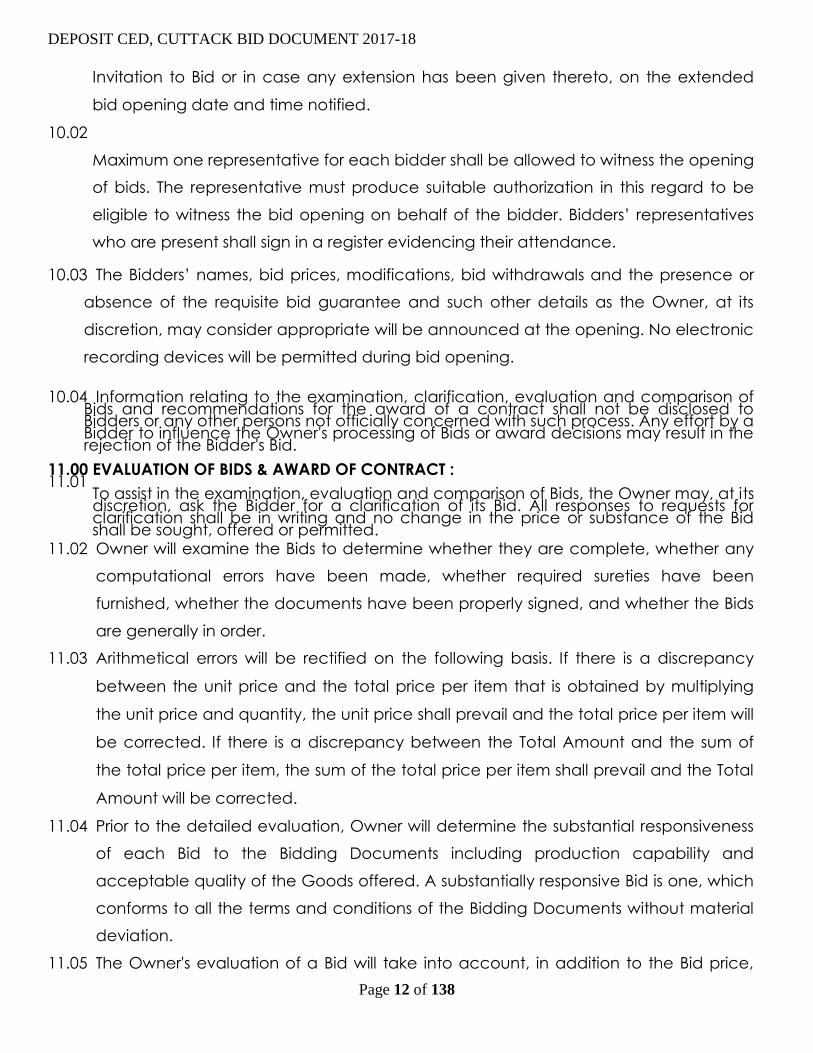
Invitation to Bid or in case any extension has been given thereto, on the extended
bid opening date and time notified.
10.02
Maximum one representative for each bidder shall be allowed to witness the opening
of bids. The representative must produce suitable authorization in this regard to be
eligible to witness the bid opening on behalf of the bidder. Bidders’ representatives
who are present shall sign in a register evidencing their attendance. 10.03 The Bidders’ names, bid prices, modifications, bid withdrawals and the presence or
absence of the requisite bid guarantee and such other details as the Owner, at its
discretion, may consider appropriate will be announced at the opening. No electronic
recording devices will be permitted during bid opening.
10.04 Information relating to the examination, clarification, evaluation and comparison of
Bids and recommendations for the award of a contract shall not be disclosed to Bidders or any other persons not officially concerned with such process. Any effort by a Bidder to influence the Owner's processing of Bids or award decisions may result in the rejection of the Bidder's Bid.
11.00 EVALUATION OF BIDS & AWARD OF CONTRACT : 11.01
To assist in the examination, evaluation and comparison of Bids, the Owner may, at its discretion, ask the Bidder for a clarification of its Bid. All responses to requests for clarification shall be in writing and no change in the price or substance of the Bid shall be sought, offered or permitted.
11.02 Owner will examine the Bids to determine whether they are complete, whether any
computational errors have been made, whether required sureties have been
furnished, whether the documents have been properly signed, and whether the Bids
are generally in order.
11.03 Arithmetical errors will be rectified on the following basis. If there is a discrepancy
between the unit price and the total price per item that is obtained by multiplying
the unit price and quantity, the unit price shall prevail and the total price per item will
be corrected. If there is a discrepancy between the Total Amount and the sum of
the total price per item, the sum of the total price per item shall prevail and the Total
Amount will be corrected.
11.04 Prior to the detailed evaluation, Owner will determine the substantial responsiveness
of each Bid to the Bidding Documents including production capability and
acceptable quality of the Goods offered. A substantially responsive Bid is one, which
conforms to all the terms and conditions of the Bidding Documents without material
deviation.
11.05 The Owner's evaluation of a Bid will take into account, in addition to the Bid price,

DEPOSIT CED, CUTTACK BID DOCUMENT 2017-18
Page 13 of 138
the following factors, in the manner and to the extent indicated in this Clause:
(a) Work Schedule
(b) Deviations from Bidding Documents 11.06 The Owner will award the Contract to the successful Bidder whose Bid has been
determined to be the lowest - evaluated responsive Bid, when the lowest bidders is
not ready and/or incapable to undertake the entire work envisaged, then the Owner
may explore the possibility of the execution of works through other bidders if they are
willing to execute at L1 rate. Such exploration shall be carried out in a sequential
order starting with L2 bidder then with L3 bidder and so on.
11.07
In case of omission of any item in the price bid or the price for the item has not been
quoted by the firm, then zero cost shall be loaded to the bid and the contract shall
be awarded with zero cost that means the firm will have to bear the cost of that item entirely
as the item price shall be considered as inclusive anywhere in other items. The bidder
shall have to give an undertaking to the effect that prices for any item not quoted
shall be treated as free supply or to be done free of cost.
12.0 EARNEST MONEY DEPOSIT (EMD):- 12.01
A) The Tender must be accompanied by Earnest Money Deposit in shape of Bank Guarantee issued
by a Public Sector Bank at Cuttack only and encashable at Cuttack or in shape of account payee
Bank Draft drawn on any scheduled bank at Cuttack issued in favour of Executive Engineer (Elect.)
CESU,C.E.D Cuttack , payable at Cuttack or NSC/Post office saving pass book or in cash.EMD shall
be 1% of the estimated cost of the individual works for which the bidder has submitted the bid. Bids
without Earnest Money deposit will be rejected out rightly.
B) The Bank Guarantee for EMD shall be strictly as per the format (Annexure-A)
prescribed by CESU. In case of deficiency such as ownership of the security bond (other
than the issuing bank), deviation from the approved format, absence of signature of
witness etc. found in the EMD Bank Guarantee, the same shall be liable for rejection
upfront. The bidder will not be given any chance to rectify the same. (c) No adjustment of any previous deposit or any amount payable from Owner shall be
entertained for EMD. The EMD amount so submitted shall not carry any interest
payable to the bidder. 12.02 The Earnest Money so deposited shall be forfeited:

DEPOSIT CED, CUTTACK BID DOCUMENT 2017-18
Page 14 of 138
(a) if the Bidder:
i) withdraws its bid during the period of bid validity specified by the Bidder in the
Bid Form; or
(b) in the case of a successful Bidder, if the Bidder fails:
(i) to sign the Contract, or
(ii) to furnish the required Contract Performance Bank Guarantee.
12.03 The EMD of unsuccessful bidders shall be returned within 30 days from the date of
finalization of the order.
13.0 OWNER’S RIGHT TO VARY QUANTITIES AT TIME OF AWARD:
While placing orders and / or during execution of contract, Owner reserve the right to increase or decrease the quantity of goods and services specified in the Schedule of
Requirement upto 10% of the tender quantity without any change in price or other
terms and conditions.
14.0 EXPERIENCE OF BIDDERS : -
The bidders are required to furnish information regarding their experience on the
following aspects as per format provided in Section – VI, Annexure III :
i. Description of similar type of work with same or higher voltage level executed
during the last three years with the name(s) of the party(s) to whom / where
supplies / erection were made.
ii. The list of testing equipments / facilities available to execute the contract
covering both OSM and Supply by the Contractor himself. Also the area of
access of the Contractor through other agency must be indicated.
iii. Purchase / work orders details (P.O / W.O No. and date only) executed
(construction work) during the last three years along with Electrical inspection
report copies and copies of user’s performance certificates.
Bids may not be considered if the past performance is found to be un-satisfactory.
15.0 DEVIATION FROM SPECIFICATION: - The bidders are requested to study the specification and the attached drawings thoroughly
before tendering so that if they make any deviations, the same are prominently brought on a
separate sheet under the headings “Deviations” as per formats provided under Section IV,
Annexure – IV & V. All such deviations to the technical & commercial terms of the specification
shall be indicated in a separate list as indicated above. In absence of such deviation schedule, it
will be presumed that the bidder has accepted all the conditions stipulated in the tender
specification, not withstanding any deviations mentioned elsewhere in the Bid. However the
acceptance of deviation is not binding on the Owner.
DEPOSIT CED, CUTTACK BID DOCUMENT 2017-18
Page 15 of 138
16.00 TAXES & DUTIES:
16.01
The contract price is inclusive of all taxes, duties, labour cess, work contract tax, cost on
Freight & Insurance charges and other levies lawfully payable on the transaction, after
discount, if any. Any changes in the taxes & duties during the contractual period shall be
borne by the Contractor. All statutory deduction like WCT, TDS etc as applicable at the
time of payment shall be deducted and to be deposited with the relevant tax
authorities.
16.02 Service Tax:- Extra
17.00 WORK COMPLETION PERIOD:
17.01 Time being the essence of the contract; the work shall be completed within 45 days of
date of issue of work order.
17.02 The bidder shall complete the field survey and dump the materials procured as per
specification, at site within first 30days of issue of work order and complete all erection
and commissioning work within next 15days.
17.03 The work shall be treated as complete when it shall be completed in all respects with all
mountings, fixtures and standard accessories which are normally supplied even though not
specifically detailed in the specification. No extra payment shall be payable for such
mounting, fittings, fixtures and accessories which are needed for safe operations of the
equipment as required by applicable code of the country though this might not have
included in the contract.
17.04
All similar components and/or parts of similar equipment supplied shall be inter-
changeable with one another. Various equipments supplied under this contract shall be
subject to CESU approval.
17.05 CESU however reserves the right to re-schedule the completion period, if required.
18.00 ENGINEER – IN – CHARGE:
For the purpose of this work, concerned Divisional Engineer for CED, Cuttack or his
authorized officer shall be the Engineer-In-Charge for this project.
19.00 PAYING OFFICER:
For the purpose of this work Executive Engineer, C.E.D , Cuttack CESU shall be the Paying
Officer.
Paying Officer shall process the bills after obtaining the following documents;
II) Invoice in Triplicate duly certified by the Concerned J.E. & SDO along with Joint
Measurement Certificate (JMC).
III) Work Completion Certificate for each completed work duly certified by the
concerned J.E, SDO.
DEPOSIT CED, CUTTACK BID DOCUMENT 2017-18
Page 16 of 138
IV) Material Utililisation Certificate (OSM), if any, duly certified by the concerned J.E &
SDO.
V) Copy of Inspection/Testing report/ Type Test Report/ Guarantee Certificate against
Contract supply items.
VI) Return of dismantled materials, if any, duly acknowledged / certified by the concerned
Section.
VII) Copies of all Statutory documents such as Valid Labour License, Electrical Project
Licenses, Service Tax payment Challan, WCT payment Challan, PAN Card and any
other documents as required by the paying Officer.
VIII) The contractor has complied with all scope of technical specification as mentioned in
the tender specification duly certified Concerned J.E & SDO.
IX) Besides above, any other standard documents as required for passing & processing the
bills for payment under this contract.
20.0 CONTRACT PERFORMANCE GUARANTEE :-
20.01
Within 15 days of issue of the Work Order or Letter of Award, whichever is earlier, the
Contractor shall submit Contract Performance, either in shape of A/C payee Bank
draft or Bank Guarantee issued by a Public Sector Bank at Cuttack, issued in favour of
the Executive Engineer, CED, CESU , Cuttack covering 10% of the total value of the
work order. The contractor may opt for deduction of PG amount from the bill also.
20.02 The said Bank Guarantee shall be prepared in the prescribed proforma as attached
in Section VI, Annexure - B. The Bank Guarantee furnished shall be executed on Non-
judicial Stamp paper worth of Rs 100/- (Rupees Hundred only), purchased in the
name of the issuing bank, as per the prevalent rules. The Bank Guarantee so
provided shall be en-cashable on the Bhubaneswar branch of the issuing Bank.
20.03 The Contract Performance Bank Guarantee shall remain valid for a period not less
than 90 days over and above the guarantee period, basing on stipulated
completion period in the W.O. towards security and acceptance thereof, failing
which the work orders (W.O) will be liable for cancellation without any further notice
with forfeiture of E.M.D.
20.04 No interest shall be allowed by the Owner on the above Performance Security
Deposit submitted by the Bidder except in case of demand draft or cash deposit
21.00 PAYMENT TERMS:
21.01 100% (Hundred Percent) of contract price including taxes and duties and deductions as
applicable shall be paid after completion of all works, envisaged including any additions
and alterations, testing & commissioning, return of dismantled materials / un-used CESU’s
Supply materials (OSM), taking over certificate and entire stretch is fully ready for

DEPOSIT CED, CUTTACK BID DOCUMENT 2017-18
Page 17 of 138
commercial operation. The Completion of Work is to be certified by the Jr. Manager &
SDO Concerned. No payment shall be released unless the accounts for utilization of
materials follow with proper certification by the concerned Junior Manager, Asst.
Manager / SDO.
21.02 No proportionate payment shall be released for the Deviation Portion in Standard of Work
and Material. The total amount involved shall be deducted and will be paid after
compliance within thirty (30) days. 21.03 GENERATION AND SUBMISSION OF BILL
a. The bills will be generated strictly basing on the JMC of the work but limiting to BoQ.
b. The bills are to be submitted by the agency to the Concerned Junior Manager only. The
bills must be accompanied with JMC (as per prescribed format) duly certified by the
agency and concerned JM and SDO. The bills without JMC as per prescribed format
duly certified by the agency and concerned JE & SDO will not be entertained by this
office.
c. Correction in the bill (regarding variation in quantity with respect to JMC) is to be
avoided.
d. The bills must accompany with the JMC, Inspection Report, Type Test Report, Completion
Certificate, and Material Purchase Invoice/ Bill in support of materials used and all other
statutory documents as per the work order.
22.00 PENALTY OF CONTRACT:
22.01
If the contractor fails to complete the works (Supply, erection, testing and commissioning
etc.) within the completion period specified in the work order or any extension granted
thereby, the contractor shall be liable for payment of penalty amounting to 0.5% (point
five percent) subject to maximum 5% (five percent) of the contract price per week of un-
finished portion of works.
16.02 The penalty for liquidated damage as mentioned above will be levied if any
deviation to be scheduled on any item of work due to the fault of the contractor is
observed.
22.02
Penalty amount can be realized from the Performance Guarantee, if the situation so
warrants.
22.03
Extension of delivery period could be with / without levy of penalty lie with the discretion
of CESU.
23.00 GUARANTEE PERIOD:
23.01
All the materials to be supplied under this contract shall be guaranteed for satisfactory
operation against defects in design and workmanship for a period of 24 months from the
date of handing over of the completed installations after commercial operation at
required voltage level.
23.02
The above guarantee certificates shall be furnished in triplicate to CESU (Executive
Engineer, CE.D, Cuttack) for his approval. Any defects noticed during the above period
DEPOSIT CED, CUTTACK BID DOCUMENT 2017-18
Page 18 of 138
should be rectified by the bidder free of cost to CESU provided such defects are due to
faulty design, bad workmanship or bad materials used on receipt of written notice from
the CESU. The contractor as notified by the CESU shall rectify any such defects within one
month failing which the CESU will set right the defects through other agency and recover
the cost so incurred either from any pending Invoices or Performance Guarantee.
24.00 REJECTION OF MATERIALS:
All the materials to be used should have conform to REC/ IS/ CESU/ CAPEX (GTP enclosed)
specification with latest amendments. In no case, sub standard materials shall be allowed to
use in this work.
In the event of the materials supplied by the contractor and/or the installation works are
found to be defective in quality and the workmanship is poor or otherwise not in conformity
with the requirements of the contract specification, CESU shall reject such materials /
services and ask the contractor in writing to replace / rectify the defects. The contractor on
receipt of such notification shall rectify or replace the defective materials and/or re-install
the work already executed, free of cost to the CESU. If the contractor fails to do so the CESU
may at his option take the following actions which could be on concurrent basis.
A) Replace or rectify such defective materials and recover the extra cost so involved plus
25% from the Contractor.
B) Terminate the contract for balance supply and erection with enforcement of penalty as
per contract.
C) May acquire the defective materials at reduced price considered acceptable under
the circumstances.
D) Forfeit the Performance Guarantee.
25.00 DOCUMENTS & DRAWINGS:
25.01
GTP is annexed for reference. Within 7 days of the effective date of contract you shall
provide three copies of an outline program of production, delivery, survey, erection,
pre- commissioning and commissioning in chart form. Included in the program will be the
detailed schedule of drawing to be submitted.
25.02
The periodic progress report as required by the CESU shall be submitted by you as per
the format prescribed by the Engineer in Charge.
26.00 APPROVAL PROCEDURE OF SUB VENDORS & DRAWINGS OF BOUGHT OUT MATERIALS:
The contractor shall submit all drawings, documents and type test reports, QAP, Name of
Sub vendor, samples (as applicable) etc, to the engineer in charge within 15 days of
award of LOA for approval. If modifications to be made if such are deemed necessary,
the contractor has to resubmit them for approval without delaying the initial deliveries or
completion of the contract work.
27.00 INSPECTION & TESTING OF MATERIAL:
27.01
All materials & equipments to be supplied under this contract shall be supplied as per
specification.
DEPOSIT CED, CUTTACK BID DOCUMENT 2017-18
Page 19 of 138
27.02
The Contractor has to produce the type test report of all Major Materials ( PSC Pole, 11KV
Pin Insulators, Stay Insulators, AB Switch, HG Fuse, LT Distribution Box, Disc Insulator, HW
Fittings, Piercing Connector, Suspension Clamp, Dead end Clamp, PVC Cable,
Channels & Angle), before purchase.
27.03
The materials procured by the contractor are to be tested at site by the representative
of owner (SDO (Elect.) of concern area/ any representative of owner, specified by
owner), as per specification before erection. It is the responsibility of the contractor to
get the materials tested before erection. If any dispute arises regarding quality of
materials, it is the liberty of CESU to send the same to Standard Testing Laboratory for
testing and in such event any expenditure to be incurred for this, shall be borne by the
contractor.
27.04
The Engineer-in-charge or his representative shall be entitled at all reasonable times
during manufacture / installation to inspect examine and test the materials at the
contractor’s premises / erection site about workmanship of the materials to be supplied
under this contract. If the said materials are being manufactured in other premises, the
contractor shall provide unhindered clearance, giving full rights to the CESU to inspect,
examine and test as if the materials were being manufactured in his premises. Such
inspection / examination and testing shall not relieve the contractor of his obligations to
execute the contract by letter and spirit.
28.00 STORE: Storing of materials from supply to erection shall be arranged by the contractor at his
own cost. No compensation shall be made by the CESU for any damage or loss of
materials during storing, transit transportation and at the time of erection.
You have to construct your own store, engage own security guards till completion and
handing over of the work to CESU.
29.00 TRANSFER AND SUB-LETTING:
The Contractor shall not sublet, transfer, assign or otherwise part with the Contract or
any part thereof, either directly or indirectly, without prior written permission of the
CESU.
30.00 ELECTRICITY, WATER, SITE OFFICE:
The Contractor shall be entitled to use for the purpose of performing the Services such as
supply of electricity and water as may be available on the Site and shall provide any
apparatus necessary for such use. The Contractor shall pay the CESU at the applicable
tariff plus the CESU’s overheads, if any, for such use. Where such supplies are not
available, the Contractor shall make his own arrangement for provision of any supplies
he may require. No compensation shall be made by the CESU for any damage or loss of
materials during storing, transit transportation and at the time of erection.
31.00 CLEARANCE OF SITE:
The Contractor’s shall from time to time during the progress of the Works clear away and
remove all surplus materials and rubbish disposal in an approved manner. On
DEPOSIT CED, CUTTACK BID DOCUMENT 2017-18
Page 20 of 138
completion of the work the Contractor shall remove all Contractors’ equipment and
leave the whole of the Site clean and in workable conditions, to the satisfaction of CESU.
The Contractor shall obtain prior approval of CESU to remove the surplus materials.
32.00 AUTHORITY FOR ACCESS:
No persons other than the employees of the Contractor and his sub-contractors shall be
allowed on the Sites except with the written consent of CESU.
Facilities to inspect the work shall at all times be afforded by the Contractor to CESU and
his representatives, authorities and officials.
33.00 ASSISTANCE WITH LOCAL REGULATIONS
The CESU shall assist to the extent possible the Contractor in ascertaining the nature and
extent of any laws, regulations orders or bye-laws and customs in India where the Goods
are to be erected, which may affect the Contractor in the performance of his
obligations under the Contract. CESU shall if so requested procure for the Contractor
copies thereof where available and information relating thereto at the Contractor’s
cost.
34.00 CONTRACTOR’S DEFAULT:
34.01
If the Contractor neglects to execute the works with due diligence and expedition or
refuses or neglects to comply with any reasonable order given to him, in writing by the
Engineer in connection with the works or contravenes the provisions or the contract, the
CESU may give notice in writing to the Contractor to make good the failure, neglect or
contravention complained of. Should the Contractor fail to comply with the notice
within thirty (7) days from the date of serving the notice, the CESU shall be at liberty to
employ other workmen and forthwith execute such part of the works as the contractor
may have neglected to do or if the CESU thinks fit, without prejudice to any other right,
he may have under the Contract to take the work wholly or in part out of the
Contractor’s hands and re-contract with any other person or persons to complete the
works or any part thereof and in that event the CESU shall have free use of all
Contractor’s equipment that may have been at the time on the Site in connection with
the works without being responsible to the Contractor for fair wear and tear thereof and
to the exclusion of any right of the Contractor over the same, and the CESU shall be
entitled to retain and apply any balance which may otherwise be due on the Contract
by him to the Contractor, or such part thereof as may be necessary, to the payment of
the cost of executing the said part of works or of completing the works as the case may
be. If the cost of completing of works or executing part thereof as aforesaid shall exceed
the balance due to the Contractor, the Contractor shall pay such excess. Such payment
of excess amount shall be independent of the liquidated damages for delay which the
Contractor shall have to pay if the completion of works is delayed.
34.02 In addition, such action by the CESU as aforesaid shall not relieve the Contractor of his
liability to pay liquidated damages for delay in completion of works.
34.03 Such action by the CESU as aforesaid the termination of the Contract under this clause
shall not entitle the Contractor to reduce the value of the Contract Performance

DEPOSIT CED, CUTTACK BID DOCUMENT 2017-18
Page 21 of 138
Guarantee nor the time thereof. The Contract Performance Guarantee shall be valid for
the full value and for the full period of the Contract including guarantee.
35.00 RIGHT OF WAY:
Right of way issues, if any, arising during execution of the works shall have no liability on the
CESU. These issues shall be settled at the sole discretion of the Contractor. CESU shall
however extend all possible help to the Contractor including discussion with the local
authorities for early resolution of these issues.
36.00 TERMINATION OF CONTRACT ON CESU’S INITIATIVE:
36.01
CESU reserves the right to terminate the Contract either in part or in full due to reasons
other than those mentioned under clause entitled ‘Contractor’s Default’. The CESU shall in
such an event give seven (7) days notice in writing to the Contractor of his decision to do
so.
36.02
The Contractor upon receipt of such notice shall discontinue the work on the date and
to the extent specified in the notice, make all reasonable efforts to obtain cancellation
of all orders and Contracts to the extent they related to the work terminated and terms
satisfactory or the CESU, stop all further sub-contracting or purchasing activity related to
the work terminated, and assist CESU in maintenance, protection, and disposition of the
works acquired under the Contract by the CESU. In the event of such a termination the
Contractor shall be paid compensation, equitable and reasonable, dictated by the
circumstance prevalent at the time of termination to be determined by the arbitrator
without stopping the work but to carry out the left over work to other agency.
36.03
If the Contractor is an individual or a proprietary concern and the individual or the
proprietor dies and if the Contractor is a partnership concern and one of the partners
dies then unless the CESU is satisfied that the legal representatives of the individual
Contractor or of the proprietor of the propriety concern and in the case of partnership,
the surviving partners, are capable of carrying out and in the case of partnership, the
surviving partners, are capable of carrying out and completing the Contract the CESU
shall be entitled to cancel the Contract as to its in completed part without being in any
way liable to payment of any compensation to the estate of deceased Contractor and
/or to the surviving partners of the Contractor’s firm on account of the cancellation of
the contract. The decision of the CESU that the legal representatives of the deceased
Contractor or surviving partners of the Contractor’s firm cannot carry out and complete
the contract shall be final and binding on the parties. In the event of such cancellation
the CESU shall not hold the estate of the deceased Contractor and/ or the surviving
partners of the Contractor’s firm liable to damages for not completing the Contract.
37.00 SAFETY PRECAUTION:
The agency shall observe all applicable regulations regarding safety as per Central
Electricity Authority (Measures relating to safety & Electric Supply) Regulations-2010, at
site. Any compensation due on account of accident at site shall be in the contractor’s
account.
38. 00 RECONCILIATION OF ACCOUNT:
DEPOSIT CED, CUTTACK BID DOCUMENT 2017-18
Page 22 of 138
The contractor shall prepare and submit a statement covering payments claimed and
the payments received vis-à-vis the works executed, for reconciliation of accounts with
the CESU. The contractor shall also prepare and submit a detailed account of CESU
Supply materials received and utilized by him for reconciliation purpose in a format to be
supplied by CESU.
39.00 MAINTENANCE OF STATUTORY RECORDS:
You will maintain all the registers, records and return under the contract labor (R&A) Act
1970 and Odisha rules made there under, The employee provident fund (M&P) Act 1952,
The Employee Insurance Act 1948, Minimum wages Act and other relevant labor laws as
applicable from time to time and produce the same for verification before the
concerned statutory authority on demand.
40.00 TAKING OVER:
40.01
Upon successful completion of all the tests performed at site on equipment / materials
supplied, erected and Commissioned by the contractor, the supply engineer shall issue
to the contractor a taking over certificate as a proof of the final acceptance of the
equipment / materials on a written request by the contractor within 10 days of
commercial operation. Such certificate shall not be un-reasonably withheld nor will the
engineer delay the issuance thereof on account of minor omission or defects, which do
not affect the commercial operation and / or cause any serious to the
equipment/material. The conditional taking over certificate can be issued if any minor
omission or defects pointed by the engineer-In –Charge / Supervising Officer / Electrical
Inspector persists. The contractor should rectify those defects within a month of
conditional T.O.C. failing which department will rectify those by replacing those
materials or engaging other agencies. The amount so involved will be fully recovered
from the contractor’s bill. Such certificate shall, however, not relieve the contractor of
any of his obligations which otherwise survive by the terms & conditions of the contract
after issuance of such certificate.
40.02
For the satisfaction of CESU about quality, the CESU shall have unreserved right for
arrangement of testing of equipment/ materials and the complete system
independently by self or any other agency chosen by the CESU. The contractor is
expected to agree and extend necessary help during such test if necessary.
41.00 FORCE MAJEURE:
The Contractor shall not be liable for any penalty for delay or for failure to perform the
contract for reasons of Force Majeure such as “acts of God, acts of the Public enemy,
acts of Govt., Fires, Flood, Epidemics, Quarantine restrictions, Strikes, Freight Embargos
and provided that the Contractor shall within ten (10) days from the beginning of such
delay notify the CESU in writing of the cause of delay. The CESU shall verify the facts and
grant extension as facts justify.
42.00 DISPUTE RESOLUTION AND JURISDICTION:

DEPOSIT CED, CUTTACK BID DOCUMENT 2017-18
Page 23 of 138
a) Any Disputes arising out of this contract shall be referred to the SE, Electrical circle,
Cuttack who shall decide the case as sole Adjudicator.
b) All disputes shall be subjected to exclusive jurisdiction of the Courts at Cuttack and
the writ jurisdiction of Hon’ble High Court of Odisha at Cuttack.
43.00 ENGAGEMENT OF SECURITY:
The Contractor shall have to engage his own security at his own cost till final handing
over of the entire completed work after commissioning to CESU.
44.00 WORKMEN COMPENSATION:
The Contractor shall take out a comprehensive insurance policy under the Workman
Compensation Act 1923, to cover such workers, who will be engaged to undertake the
jobs covered under this Work Order and a copy of this insurance policy will be given to
CESU and Engineer-in-charge solely for their information, reference and records. The
Contractor shall ensure that such insurance policies are kept at all times valid.
45.00 CONTRACTOR’S CONSTRUCTION MANAGEMENT:
Contractor’s Representative:
The Contractor’s shall, employ adequate numbers of competent representatives to
supervise & carry out each item of works on Site. They shall be fluent in the Odia
language for day to day communications. Their names shall be communicated in writing
to CESU before works on Site begins.
Any instruction or notice which CESU gives to the Contractor’s representatives shall be
deemed to have been given to the Contractor.
At least one of the Contractor’s competent representatives on each Site shall be fluent
in speaking, writing, reading and understanding Odia / English.
46.00 OBJECTION TO CONTRACTOR’S EMPLOYEES:
The Contractor shall, upon the CESU’s written instructions, remove from the Works any
person employed by him for execution of the Work, who misconduct himself or is found
to be incompetent or negligent.
47.00 CORRESPONDENCE:
47.01 Any notice to the contractor under the terms of the contract shall be served by hand to
the authorized local representative of the contractor and copy by post to the
contractor’s principal place of business.
47.02 Any notice to CESU shall be served to the Executive Engineer, CED, Cuttack in the same
manner.
48.00 ACCEPTANCE:
The bidder has to acknowledge receipt of this award of contract along with the
Annexure(s) ensuring submission of one copy of this letter of award duly signed on each

DEPOSIT CED, CUTTACK BID DOCUMENT 2017-18
Page 24 of 138
page as a proof of your acceptance of this contract within 03 ( Three) days from the
date of issue of the work order.
Non Acceptance or Conditional acceptance of the Work Order within the stipulated
period, Work order shall be cancelled automatically.
Any other terms & conditions not mentioned here shall be as per the prevailing rule of
CESU, Bill of quantities and other schedules, which shall form part of this contract.
SECTION - II
INFORMATION TO BIDDERS
DEPOSIT CED, CUTTACK BID DOCUMENT 2017-18
Page 25 of 138
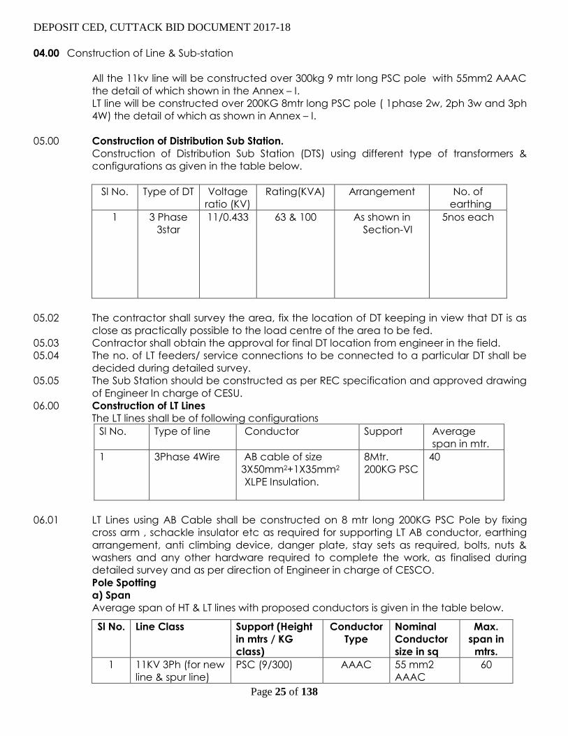
04.00 Construction of Line & Sub-station
All the 11kv line will be constructed over 300kg 9 mtr long PSC pole with 55mm2 AAAC
the detail of which shown in the Annex – I.
LT line will be constructed over 200KG 8mtr long PSC pole ( 1phase 2w, 2ph 3w and 3ph
4W) the detail of which as shown in Annex – I.
05.00 Construction of Distribution Sub Station.
Construction of Distribution Sub Station (DTS) using different type of transformers &
configurations as given in the table below.
Sl No. Type of DT Voltage
ratio (KV)
Rating(KVA) Arrangement No. of
earthing
1 3 Phase
3star
r
a
t
e
d
11/0.433 63 & 100 As shown in
Section-VI
5nos each
05.02 The contractor shall survey the area, fix the location of DT keeping in view that DT is as
close as practically possible to the load centre of the area to be fed.
05.03 Contractor shall obtain the approval for final DT location from engineer in the field.
05.04 The no. of LT feeders/ service connections to be connected to a particular DT shall be
decided during detailed survey.
05.05 The Sub Station should be constructed as per REC specification and approved drawing
of Engineer In charge of CESU.
06.00 Construction of LT Lines
The LT lines shall be of following configurations
Sl No. Type of line Conductor Support Average
span in mtr.
1 3Phase 4Wire AB cable of size
3X50mm2+1X35mm2
XLPE Insulation.
8Mtr.
200KG PSC
40
06.01 LT Lines using AB Cable shall be constructed on 8 mtr long 200KG PSC Pole by fixing
cross arm , schackle insulator etc as required for supporting LT AB conductor, earthing
arrangement, anti climbing device, danger plate, stay sets as required, bolts, nuts &
washers and any other hardware required to complete the work, as finalised during
detailed survey and as per direction of Engineer in charge of CESCO.
Pole Spotting
a) Span
Average span of HT & LT lines with proposed conductors is given in the table below.
Sl No. Line Class Support (Height
in mtrs / KG
class)
Conductor
Type
Nominal
Conductor
size in sq
Max.
span in
mtrs.
1 11KV 3Ph (for new
line & spur line)
PSC (9/300)
AAAC 55 mm2
AAAC
60

DEPOSIT CED, CUTTACK BID DOCUMENT 2017-18
Page 26 of 138
(b) Road Crossing
At all major road crossings, the poles shall be fitted with strain type insulators but the
ground clearance at the roads under maximum temperature and in still air shall be
such that even with conductor broken in adjacent span, ground clearance of the
conductor from the road surfaces shall not be less than 6.1 meters.
(c) Power Line Crossings
Where the proposed lines require to cross over another line of the same voltage or
lower voltage, provisions to prevent the possibility of its coming into contact with other
overhead lines shall be made in accordance with the Central Electricity Authority
(Measures relating to Safety & Electric Supply) Regulations, 2010, as amended from time
to time. All the works related to the above proposal shall be deemed to be included in
the scope of the Contractor. Where existing lines of higher voltages are to be crossed
under another line, the bidder shall take up suitable re-routing so as to obtain necessary
sectional clearances, other wise crossing through 11 kV cable shall be proposed.
(d) Telecommunication Line Crossings
The angle of crossing shall be as near to 90 degree as possible. However, deviation to
the extent of 30 degree may be permitted under exceptionally difficult situations.
HT line shall be routed with requisite suppresion with parallel telecom line to avoid
inductance during faults.
(d) Details Enroute.
All topographical details, permanent features, such as trees, telecommunication lines,
building etc. 5.5 meter on either side of the alignment shall be detailed on the route
plan.
(e) Clearance from Ground, Building, Trees etc.
Clearance from ground, buildings, trees and telephone lines shall be provided in
conformity with the Central Electricity Authority (Measures relating to Safety & Electric
Supply) Regulations, 2010 as amended upto date. The bidder shall select the height of
the poles such that all electrical clearances are maintained.
(f) The minimum planting depth of poles shall be governed by IS : 1678. However, if due
to the ground conditions, e.g. water logged area etc. depth of planting of poles shall
be suitably increased the bidder will supply the poles of suitable height in order to
maintain the required clearances, the vendor will submit the details of the same on
case to case basis.
(i) Guarding mesh shall be used in all electric line / telecom line / road / drain / canal
crossing and at all points as per statutory requirements. The bidder shall provide & install
anti climbing devices and danger plates on all poles and DT stations.
2 LT 3Ph 4W PSC (8/200) ABC 3x50+1x35
40
DEPOSIT CED, CUTTACK BID DOCUMENT 2017-18
Page 27 of 138
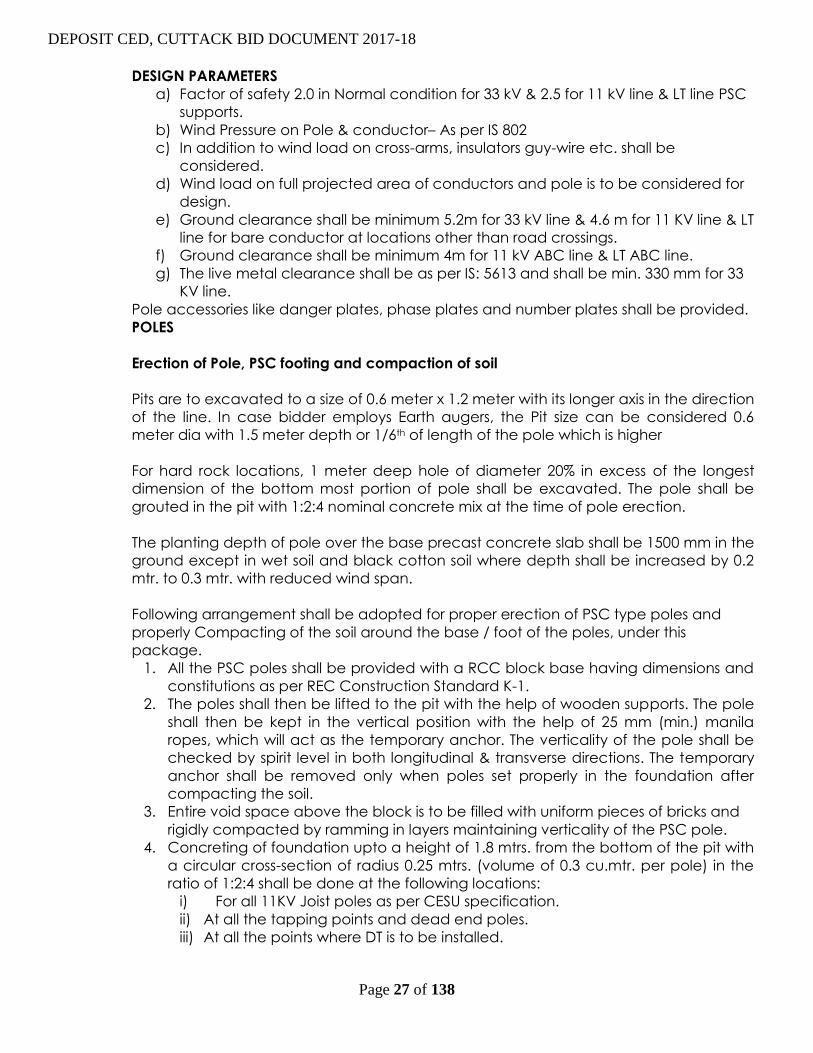
DESIGN PARAMETERS
a) Factor of safety 2.0 in Normal condition for 33 kV & 2.5 for 11 kV line & LT line PSC
supports.
b) Wind Pressure on Pole & conductor– As per IS 802
c) In addition to wind load on cross-arms, insulators guy-wire etc. shall be
considered.
d) Wind load on full projected area of conductors and pole is to be considered for
design.
e) Ground clearance shall be minimum 5.2m for 33 kV line & 4.6 m for 11 KV line & LT
line for bare conductor at locations other than road crossings.
f) Ground clearance shall be minimum 4m for 11 kV ABC line & LT ABC line.
g) The live metal clearance shall be as per IS: 5613 and shall be min. 330 mm for 33
KV line.
Pole accessories like danger plates, phase plates and number plates shall be provided.
POLES
Erection of Pole, PSC footing and compaction of soil
Pits are to excavated to a size of 0.6 meter x 1.2 meter with its longer axis in the direction
of the line. In case bidder employs Earth augers, the Pit size can be considered 0.6
meter dia with 1.5 meter depth or 1/6th of length of the pole which is higher
For hard rock locations, 1 meter deep hole of diameter 20% in excess of the longest
dimension of the bottom most portion of pole shall be excavated. The pole shall be
grouted in the pit with 1:2:4 nominal concrete mix at the time of pole erection.
The planting depth of pole over the base precast concrete slab shall be 1500 mm in the
ground except in wet soil and black cotton soil where depth shall be increased by 0.2
mtr. to 0.3 mtr. with reduced wind span.
Following arrangement shall be adopted for proper erection of PSC type poles and
properly Compacting of the soil around the base / foot of the poles, under this
package.
1. All the PSC poles shall be provided with a RCC block base having dimensions and
constitutions as per REC Construction Standard K-1.
2. The poles shall then be lifted to the pit with the help of wooden supports. The pole
shall then be kept in the vertical position with the help of 25 mm (min.) manila
ropes, which will act as the temporary anchor. The verticality of the pole shall be
checked by spirit level in both longitudinal & transverse directions. The temporary
anchor shall be removed only when poles set properly in the foundation after
compacting the soil.
3. Entire void space above the block is to be filled with uniform pieces of bricks and
rigidly compacted by ramming in layers maintaining verticality of the PSC pole.
4. Concreting of foundation upto a height of 1.8 mtrs. from the bottom of the pit with
a circular cross-section of radius 0.25 mtrs. (volume of 0.3 cu.mtr. per pole) in the
ratio of 1:2:4 shall be done at the following locations:
i) For all 11KV Joist poles as per CESU specification.
ii) At all the tapping points and dead end poles.
iii) At all the points where DT is to be installed.
DEPOSIT CED, CUTTACK BID DOCUMENT 2017-18
Page 28 of 138
iv) At all the points as per REC construction dwg. No. A-10 (for the diversion
angle of 10-60 degree)
v) Within a maximum distance of 1 km from the last Jhama filled pole structure.
vi) Both side poles at all the crossing for road, nallaha railway crossings etc.
vii) Where Rail poles, double pole and four pole structures.
5. In case the route of 33/11 kV lines encounters marshy low laying area, special type
of foundations shall be used. In such a case, difference in excavation quantity,
concreting & reinforcement between special foundation and normal foundation
shall be paid extra as per Delhi Schedule of Rate (DSR) applicable on the date of
bid opening. No other payment incidental to special foundation locations shall be
made to the contractor.
Earthing of Poles
In 33/11 kV & LT line, each pole shall be earthed with coil type earthing as per REC
Construction Standard J-1.
All DP & the poles on both sides of railway, Telecommunication, road, drain & river
crossing shall be earthed by pipe earthing as per REC Construction Standard J-2.
Extension Pole
PSC pole with pole extension arrangement up to two meters shall be used at low
ground level locations for maintaining ground clearance and for road crossings for HT &
LT lines. Extension of poles shall be by use of 100x50x6mm galvanise channel up to three
meters. A overlap of one meter shall be maintained with the pole.
Wherever such extended poles will be used the span on both sides of the extension
pole shall be suitably reduced to take care of loading on the pole.
PROVIDING OF GUYS/STRUT POLES TO SUPPORTS
Strut poles/flying guys wherever required shall be installed on various pole locations as
per REC construction standards .For selection of guing locations REC guidelines &
construction practices shall be followed.
In this work anchor type guy sets are to be used. These guys shall be provided at
i) angle locations
ii) dead end locations
iii) T-off points
iv) Steep gradient locations.
v) Double Pole, & four poles
The stay rod should be placed in a position so that the angle of rod with the vertical
face of the pit is 300/450 as the case may be.
G.I. stay wires of size 7/3.15 mm (10 SWG) with GI turn buckle rod of 16 mm dia & 16 mm
dia GI stay stay rods, shall be used for 11KV & LT line.
G.I. stay wires of size 7/4 mm with GI turn buckle rod of 20 mm dia & 20 mm dia GI stay
stay rods, shall be used for 33 KV line.
DEPOSIT CED, CUTTACK BID DOCUMENT 2017-18
Page 29 of 138
For double pole structure (DP), four stays along the line, two in each direction and two
stays along the bisection of the angle of deviation (or more) as required depending on
the angle of deviation are to be provided. Hot dip galvanised stay sets are to be used.
The anchor plate shall be fixed to 200mm x 200mm MS plate of 6mm thickness. M.S. rod
with a bolt arrangement at one end and other end is given shape of 40mm dia circle to
bind one end of the stay wire. The anchor plate shall be buried in concrete. The
dimensions for concreting & earth & boulder fill shall be as per the drawing mentioned
in clause no 3.01.00.
The turn buckle shall be mounted at the pole end of the stay and guy wire so fixed that
the turn buckle is half way in the working position, thus giving the maximum movement
for tightening or loosening.
If the guy wire proves to be hazardous, it should be protected with suitable asbestos
pipe filled with concrete of about 2 m length above the ground level, painted with
white and black strips so that, it may be visible at night.
CROSS ARMS
Cross Arms For 11 KV Overhead Power Lines shall be made out of 100x50x6 mm and 75 x
40 x6 mm M.S. channel. Cross Arms made out of M.S. angle shall not be used. Cross
arms shall conform to specification given under the head miscellaneous items in this
specifications.
Fixing of Cross Arms
After the erection of supports and providing guys, the cross-arms are to be mounted on
the support with necessary clamps, bolts and nuts. The practice of fixing the cross arms
before the pole erection can also be followed. In case, the cross-arm shall be mounted
after the pole is erected, the lineman should climb the pole with necessary tools. The
cross-arm shall then tied to a hand line and pulled up by the ground man through a
pulley, till the cross-arm reaches the line man. The ground man should station himself on
one side, so that if any material drops from the top of the pole, it may not strike him. All
the materials should be lifted or lowered through the hand line, and should not be
dropped.
INSTALLATION OF LINE MATERIALS
Insulator and Bindings
Prior to fixing, all insulators shall be cleaned in a manner that will not spoil, injure or
scratch surface of the insulator, but in no case shall any oil be used for that purpose. Pin
insulators shall be used on all poles in straight line and disc or shackle insulators on angle
and dead end poles. Damaged insulators and fittings, if any, shall not be used. The
insulator and its pin should be mechanically strong enough to withstand the resultant
force due to combined effect of wind pressure and weight of the conductor in the
span.
DEPOSIT CED, CUTTACK BID DOCUMENT 2017-18
Page 30 of 138
Strain insulators shall be used at terminal locations or dead end locations and where the
angle of deviation of line is more than 100. Strain insulators shall be used at major
crossings.
The pins for insulators shall be fixed in the holes provided in the cross-arms and the pole
top brackets. The insulators shall be mounted in their places over the pins and
tightened. In the case of strain or angle supports, where strain fittings are provided for
this purpose, one strap of the strain fittings is placed over the cross-arm before placing
the bolt in the hole of cross-arms. The nut of the straps shall be so tightened that the
strap can move freely in horizontal direction.
Handling of Conductor and Earth wire
Running Out of the Conductors: The contractor shall be entirely responsible for any
damage to the pole or conductors during stringing. Care shall be taken that the
conductors do not touch and rub against the ground or objects, which could scratch
or damage the strands.
The sequence of running out shall be from the top to down i.e. the top conductor shall
be run out first, followed in succession by the side conductors. Unbalanced loads on
poles shall be avoided as far as possible. When lines being erected run parallel to
existing energized power lines, the Contractor shall take adequate safety precautions
to protect personnel from the potentially dangerous condition.
Monitoring of Conductors during Stringing
The conductor shall be continuously observed for loose or broken strands or any other
damage during the running out operations. Repair to conductors, if necessary, shall be
carried out with repair sleeves. Repairing of the conductor surface shall be carried out
only in case of minor damage, scuff marks, etc. The final conductor surface shall be
clean, smooth and free from projections, sharp points, cuts, abrasions, etc. The
Contractor shall be entirely responsible for any damage to the poles during stringing.
Crossings
All crossings shall be at right angles. Derricks or other equivalent methods ensuring that
normal services need not be interrupted nor damage caused to property shall be used
during stringing operations where roads, channels, telecommunication lines, power lines
and railway lines have to be crossed. The contractor shall coordinate with state
electricity board for obtaining work permit and shut down of the concerned line.
However. shut down shall be obtained when working at crossings of overhead power
lines. The Contractor shall be entirely responsible for the proper handling of the
conductor, earthwire and accessories in the field.
Guarding shall be provided at major crossings. The Guardings shall consists of GI guard
cross arm of length 2.5 mtrs made out of 75 x 40 x 6 mm channel & shall be hot dipped
galvanized generally conforming to IS:2633/72. The clamps shall also be hot dipped
galvanized generally conforming to IS:2633/72. Guardings shall be erected with ground
& line clearances as per the I.E. rules. The guarding shall be provided with GI wire 8 SWG
for 11KV & LT line & 4 SWG for 33KV line. Binding wire & suitable I bolt & nut bolts for cross
arm to cross arm. Guard wire shall be separately earthed at both ends. For 33KV line
guarding arrangement shall be as per REC construction standard M6.

DEPOSIT CED, CUTTACK BID DOCUMENT 2017-18
Page 31 of 138
Anti-climbing Devices
Anti Climbing Devices shall be provided with G.I. Barbed wire, they shall be provided
and installed by the Contractor for all poles. The barbed wire shall conform to IS:278
(Grade A1). The barbed wires shall be given chromating dip as per procedure laid
down in IS:1340.
Painting Materials
All the metal parts except G.I. parts are to be painted with one coat of red oxide and
one coat of aluminium paint.
STRINGING OF CONDUCTOR
The works include spreading of conductors or HT/LT AB Cables without any damage
and stringing with proper tension without any kinks/damage including binding of
conductor at pin points, jumpering at cut points etc. The ground & line clearances at
road crossings along roads, L.T. crossings & other crossings shall be as per the relevant
Central Electricity Authority (Measures relating to Safety & Electric Supply) Regulations,
2010.
While transporting conductors drums to site, precautions are to be taken so that the
conductor does not get damaged. The drum shall be mounted on cable drum support.
The direction of rotation of the drum shall be according to the mark in the drum so that
the conductor could be drawn. While drawing the conductor, it shall not rub causing
damage. The conductor shall be passed over poles on wooden or alluminium snatch
block (pulley) mounted on the poles for this purpose.
The conductor shall be pulled through come-along clamps to stringing the conductor
between the tension locations.
Conductor splices shall not crack or otherwise be susceptible to damage in the
stringing operation. The Contractor shall use only such equipment / methods during
conductor stringing which ensures complete compliance in this regard. All the joints
including mid span joints on the conductor and earth-wire shall be of the compression
type, in accordance with the recommendations of the manufacturer, for which all
necessary tools and equipment like compressors, dies, etc., shall be obtained by the
Contractor. Each part of the joint shall be cleaned by wire brush till it is free of rust or
dirt, etc., and be properly greased with anti-corrosive compound, before the final
compression is carried out with the compressors. After completing the jointing,
tensioning operation shall be commenced.
All the joints or splices shall be made at least 15 meters away from the pole. No joints or
splices shall be made in spans crossing over main roads, railways and small river spans.
Not more than one joint per sub-conductor per span shall be allowed. The compression
type fittings shall be of the self centering type. After compressing the joint, the
alluminium sleeve shall have all corners rounded; burrs and sharp edges removed and
smoothened.
During stringing of conductor to avoid any damage to the joint, the contractor shall use
a suitable protector for mid span compression joints in case they are to be passed over
pulley blocks / aerial rollers. The pulley groove size shall be such that the joint along with
protection can be passed over it smoothly.

DEPOSIT CED, CUTTACK BID DOCUMENT 2017-18
Page 32 of 138
TAPPING ARRANGEMENT FROM EXISTING 11KV LINE
Tapping of existing 11kV line shall be taken by providing a horizontal cross arm below
the existing V cross arm of the pole & mounting disc insulators on it. The tapping
conductors may be guided by providing pin insulators as required. A new two pole
structure shall be erected within 10-15 meters of this tapping pole & the new line will
emerge from this two pole structure with disc insulators. The Taping pole to the double
pole conductor tension should be such that it avoids looseness & sag to the extent
possible & it should avoid extra tension on the tapping pole.
Wherever the proposed spur line length is more than two km after the tapping an AB
switch arrangement shall be provided at the double pole for isolation of the line.
Aligning/re-erection of tilted/bent poles wherever found in the route of line along with
strengthening of its foundation is in the scope of the bidder.
Before undertaking the Re-conductoring work in the given line, the bidder shall make
assessment of type and quantity of the existing conductor in consultation/presence of
owner’s representative.
While Re-conductoring of 11 KV line, disconnection/connection of existing Distribution
Transformer shall be in the scope of the contractor/bidder. The supply and erection of
line material for achieving the DT disconnection and connection shall be in the scope
of the contractor.
The empty conductor drums, available after laying of conductor, shall be disposed of
by the contractor at his cost. These drums may be used for rewinding of Conductor
removed from the line at the later stage of Re-conductoring work.
Any other work not mentioned above exclusively but required for accomplishing
desired work will be in the scope of the bidder/contractor.
For all above activities shut down will be provided for the line by owner. Restoring the
disturbance/damage caused by above activities to the existing infrastructure e.g. road,
water/sewerage pipes, telecommunication lines etc. will be in the scope of the
bidder/contractor.
While Repairing & Replacing the equipment, if any equipment gets damaged due to
negligent handling of the contractor the same shall be replaced by the contractor, at
his cost, to the owner/employer’s satisfaction.
Survey of existing lines
Survey shall have to be carried out by the contractor of existing lines.
Span
Since the work shall be done on the existing line, the existing span shall be maintained.
However, if any new pole is required to be erected along the route of existing line, the
span should be as near as possible to the basic design span indicated below.
11 KV line : 68 meter

DEPOSIT CED, CUTTACK BID DOCUMENT 2017-18
Page 33 of 138
SECTION - III
TECHNICAL SPECIFICATION

DEPOSIT CED, CUTTACK BID DOCUMENT 2017-18
Page 34 of 138
TECHNICAL SPECIFICATION FOR 11KV LINE MATERIALS
SUPPORT POLES, CROSSARMS AND NUTS & BOLTS
01.00 SCOPE
This Specification covers Design, Engineering, Manufacture, testing, inspection before
despatch, forwarding, packing, transportation to site, Insurance (both during transit &
storage), Storage, Erection, Supervision, testing and commissioning of 11KV, support
Poles, Cross Arms and Bolts & Nuts. for use in the networks of CESU, Orissa
The equipment offered shall have been successfully type tested and the design shall
have been satisfactory operation for a period not less than two years on the date of bid
opening. Compliance shall be demonstrated by submitting with the bid, (i)
authenticated copies of the type test reports and (ii) performance certificates from the
users.
The scope of supply includes the provision of type tests. Rates of type tests shall be
given in the appropriate price schedule of the bidding document and will be
considered for evaluation. The Collector & District Magistrate, Puri reserves the right to
waive type tests as indicated in the section on Quality Assurance. Inspection and
Testing in this specification.
The line support poles and crossarms shall conform in all respects to highest standards of
engineering, design, workmanship, this specification and the latest revisions of relevant
standards at the time of offer and the Collector & District Magistrate, Puri shall have the
power to reject any work or material, which, in his judgment, is not in full accordance
therewith.
02.00 GENERAL
The line support poles and crossarms shall be designed to carry the line conductors with
the necessary insulators and all other fittings and equipment under the conditions
specified.
Poles may be manufactured from concrete (prestressed) or steel.
Pole crossarms are normally constructed of steel and shall be bolted to the pole.
CESU use a V- crossarm on the 11KV line structures at intermediate and right angle
locations to reduce problems from birds bridging insulators. The Bidder’s crossarm
design must provide a similar level of protection from bird contact and explain how this
is achieved from the offered design.
03.00 DESIGN REQUIREMENT
In order to limit the range of materials required for line construction, maintenance and
repair the Contractor shall limit the number of different types of support structures and
crossarms as far as possible.
The following are minimum requirements:
Pole top fixings and crossarms :
For any particular pole function, the pole top equipment shall be identical
regardless of the height of the structure.

DEPOSIT CED, CUTTACK BID DOCUMENT 2017-18
Page 35 of 138
The number of crossarm types for a particular voltage and conductor size shall
be limited to three types.
Fixing bolts and nuts for crossarms and bracing straps shall be limited to two sizes
by diameter (M16 and M20)
The line support poles and crossarms shall be designed to the following
requirements:
The wind pressures to be applied to the conductors, poles and crossarms are
specified in IS 5613 (Part 1/ Section 1): 1995 and as stipulated in the Service
Conditions.
Three wind zones are found within the state of Orissa and the design of structures
shall take account of this fact. The Bidder shall take account of the wind loading
regimes together with the respective terrain category necessary for the projects
for which he is bidding and shall propose the design of support poles and
crossarms which will prove most effective for the project and for the Employer’s
system.
The working load on the support poles and crossarms should correspond to those
that are likely to come onto the structure during its working life. Existing designs
meet system requirements where working loads are applied at a point 600 mm
from the top of the pole. The offered design shall meet requirements with the
point of application of the load as per bidder’s design but not more than 600
mm from the top of the pole.
The structures shall be planted directly into the ground with a planting depth as
per IS 1678: 1978 and as stipulated in this specification.
All structures shall have a depth mark made at a point 3 meters from the butt
end. This mark shall be in the form of a horizontal line with “3m” engraved directly
below the line. In the case of steel structures the mark shall be embossed or
indented before surface treatment.
Pole details provided in this specification are indicative of poles used on the
CESU distribution system, or available as standard designs. The Bidder must
determine the requirements of the design offered and select suitable poles to
deliver the specified performance. The inclusion of a particular size in the
specification does not indicate approval of the pole for any function.
04.00 PSC POLES
PSC Poles shall be of solid rectangular type with an overall length of 8.0 M 200kg for LT
support & 9.0 M 300kg PSC pole suitable for use in 11KV overhead power lines and
double pole and for distribution S/S as indicated separately in the Analysis.
04.01 APPLICABLE STANDARDS
Except when they conflict with specific requirements in this Specification, the PSC poles
shall comply with the relevant provisions made in the following Indian Standards or the
latest versions thereof.
a) IS: 1678, Specification for prestressed concrete poles for overhead power,
traction and telecommunication lines
b) IS: 2905, Method of test for concrete poles for overhead power and
telecommunications lines.

DEPOSIT CED, CUTTACK BID DOCUMENT 2017-18
Page 36 of 138
c) IS: 7321, Code of Practice for selection, handling and erection of concrete
poles for overhead power and telecommunication lines
04.02 TERMINOLOGY
For the purpose of this specification, following definitions shall apply:-
04.03 AVERAGE PERMANENT LOAD
That fraction of the working load which may be considered of long duration over a
period of one year
04.04 LOAD FACTOR
The ratio of ultimate transverse load to the transverse load at first crack.
04.05 TRANSVERSE
The direction of the line bisecting the angle contained by the conductor at the pole. In
the case of a straight run, this will be normal to the run of the line.
04.06 Transverse Load at First Crack
For design, the transverse load at first crack shall be taken as not less than the value of
the working load.
04.07 WORKING LOAD
The maximum load in the transverse direction, that is ever likely to occur, including the
wind pressure on the pole. This load is assumed to act at a point 600mm below the top
with the butt end of the pole planted to the required depth as intended in the design
04.08 Ultimate Failure
The condition existing when the pole ceases to sustain a load increment owing to either
crushing of concrete, or snapping of the prestressing tendon or permanent stretching of
the steel in any part of the pole.
04.09 Ultimate Transverse Load
The load at which failure occurs, when it is applied at a point 600mm below the top
and perpendicular to the axis of the pole along the transverse direction with the butt
end of the pole planted to the required depth as intended in the design.
04.10 Application
04.11 8.0 M Poles (200 Kg)
These poles shall be used at tangent locations for L.T. lines in wind pressure zones of
100kg/M2 in accordance with REC Construction Standards No. A-5.
04.12 a.9.0 M Poles (300 Kg)
These poles shall be used for11kv line double pole structures of distribution Sub Station
as per REC Construction Standards F-2 to F-4 and for special locations in 11 KV and L.T
Lines, such as road crossing etc.
04.13 Material
04.14 Cement
DEPOSIT CED, CUTTACK BID DOCUMENT 2017-18
Page 37 of 138
The cement used in the manufacture of prestressed concrete poles shall be ordinary or
rapid hardening Portland cement conforming to IS:269-1976(Specification for ordinary
and low heat Portland cement) or IS: 8041 E-1978(Specification for rapid hardening
Portland cement).
04.15 Aggregates
Aggregates used for the manufacture of pre-stressed concrete poles shall confirm to
IS:383 (Specification for coarse and fine aggregates from natural sources for concrete).
The nominal maximum size of aggregates shall in no case exceed 12mm.
04.16 Water
Water should be free from chlorides, sulphates, other salts and organic matter.
Potable water will be generally suitable.
04.17 Admixture
Admixture should not contain Calcium Chloride or other Chlorides and salts which
are likely to promote corrosion of pre-stressing steel. The admixture shall conform
to IS 9103.
04.18 Pre-Stressing Steel
The pre-stressing steel wires including those used as untensioned wires should
conform to IS: 1785 (Part-I) (Specification for plain hard-drawn steel wire for
prestressed concrete, Part-I cold drawn stress relieved wire), IS 1785 (Part-II)
(Specification for plain hard-drawn steel wire) or IS:6003 (Specification for
indented wire for prestressed concrete).The type designs given in the annexure
are for plain wires of 4 mm diameter with a guaranteed ultimate strength of 175
kg/mm2 and for plain wires of 5mm diameter with a guaranteed ultimate strength
of 160 kg/mm2.
All prestressing steel shall be free from splits, harmful scratches, surface flaws,
rough, aged and imperfect edges and other defects likely to impair its use in
prestressed concrete.
04.19 Concrete Mix
The concrete mix shall be designed to the requirements laid down for controlled
concrete (also called design mix concrete) in IS: 1343-1980(code of practice for
prestressed concrete) and IS: 456-1978 (Code of practice for plain and reinforced
concrete), subject to the following special conditions;
a) Minimum works cube strength at 28 days should be at least 420 Kg/cm2.
b) The concrete strength at transfer should be at least 210 kg/cm2.
c) The mix should contain at least 380kg. Of cement per cubic meter of concrete.
d) The mix should contain as low a water content as is consistent with adequate
workability. If it becomes necessary to add water to increase the workability, the
cement content also should be raised in such a way that the original value of
water cement ratio is maintained.

DEPOSIT CED, CUTTACK BID DOCUMENT 2017-18
Page 38 of 138
04.20 Design Requirements
The poles shall be designed for the following requirements:
a) The poles shall be planted directly in the ground with a planting depth as per IS:
1678. Wherever, planting depth is required to be increased beyond the specified
limits or alternative arrangements are required to be made, on account of ground
conditions e.g. water logging etc., the same shall be in the scope of the bidder at
no extra cost to owner. The bidder shall furnish necessary design
calculations/details of alternative arrangements in this regard.
b) The working load on the poles should correspond to those that are likely to
come on the pole during their service life.
c) The factor of safety for all poles 9.0 Mts. shall not be less than 2.0 and for 8.0 M
poles, the factor of safety shall not be less than 2.5.
d) The average permanent load shall be 40% of the working load.
e) The F.O.S against first load shall be 1.0.
f) At average permanent load, permissible tensile stress in concrete shall be
30Kg/cm2.
g) At the design value of first crack load, the modulus of rupture shall not exceed
53.0 kg/cm2 for M –40.
h) The ultimate moment capacity in the longitudinal direction should be at least
on fourth of that in the transverse direction.
g) At the design value of first crack load, the modulus of rupture shall not exceed
53.0 kg/cm2 for M –40.
h) The ultimate moment capacity in the longitudinal direction should be at least
on fourth of that in the transverse direction.
i) The maximum compressive stress in concrete at the time of transfer of pre-stress
should not exceed 0.8 times the cube strength.
j) The concrete strength at transfer shall not be less than half, the 28 days strength
ensured in the design, i.e. 40O x 0.5 = 200kg/cm2.
04.21 Dimensions and Reinforcement
The cross-sectional dimensions and the details of pre-stressing wires should
conform to the particulars given in the annexure.
The Provision of holes for fixing cross-arm and other fixtures should conform to the
REC specification No. 15/1979.

DEPOSIT CED, CUTTACK BID DOCUMENT 2017-18
Page 39 of 138
04.23 Manufacture
All pre-stressing wires and reinforcements shall be accurately fixed and
maintained in position during manufacture. The untensioned reinforcement, as
indicated in the drawings, should be held in position by the use for stirrups which
should go round all the wires.
All wires shall be accurately stretched with uniform prestress in each wire. Each
wire or a group of wires shall be anchored positively during casing. Care should be
taken to see that the anchorages do not yield before the concrete attains the
necessary strength.
04.24 Cover
The cover of concrete measured from outside of pre-stressing tendon shall be
normally 20mm.
04.25 Welding and Lapping of Steel
The high tensile steel wire shall be continuous over the entire length of the tendon.
Welding shall not be allowed in any case. However, jointing or coupling may be
permitted provided the strength of the joint or coupling is not less than the
strength of each individual wire.
04.26 Compacting
Concrete shall be compacted by spinning, vibrating, shocking or other suitable
mechanical means. Hand compaction shall not be permitted;
04.27 Curing
The concrete shall be covered with layer of sacking, canvass, hessian or similar
absorbent material and kept constantly we up to the time when the strength of
concrete is at least equal to the minimum strength of concrete at transfer of
prestress. Thereafter, the pole may be removed from the mould and watered at
intervals to prevent surface cracking of the unit, the interval should depend on the
atmospheric humidity and temperature.
The prestressing wires shall be de-tensioned only after the concrete has attained
the specified strength at transfer(i.e. 200 or 210 kg/cm2, as applicable). The cubes
cast for the purpose of determining the strength at transfer should be cured, as far
as possible, under conditions similar to those under which the poles are cured. The
transfer stage shall be determined based on the daily tests carried out on concrete
cubes till the specified strength indicated above is reached. Thereafter the test on
concrete shall be carried out as detailed in IS:1343 (Code of practice for
prestressed concrete). The manufacturer shall supply, when required by the owner
or his representative, result of compressive test conducted in accordance with
IS:456 (Code of practice for plain an reinforced concrete) on concrete cubes
made from the concrete used for the poles. If the owner so desired, the
manufacturer shall supply cubes for test purposes and such cubes shall be tested in
accordance with IS:456 (Code of practice for plain and reinforced concrete).

DEPOSIT CED, CUTTACK BID DOCUMENT 2017-18
Page 40 of 138
04.32 Marking
The detensioning shall be done by slowly releasing the wires, without imparting
shock sudden load to the poles. The rate of detensioning may be controlled by any
suitable mean either mechanical (screw type) or hydraulic
The poles shall not be detensioned or released by cutting the prestressing wires
using flames or bar croppers while the wires are still under tension.
04.28 Lifting Eye-Hooks or Holes
Separate eye-hooks or holes shall be provided for handling the transport, one each
at a distance of 0.15 times the overall length, from either end of the pole. Eye-
hooks, if provided, should be properly anchored and should be on the face that
has the shorter dimension of the cross-section. Holes, if provided for lifting purposes,
should be perpendicular to the broad face of the pole.
04.29 Holes for Cross Arms etc
Sufficient number of holes shall be provided in the poles for attachment of cross
arms and other equipments.
04.30 Stacking & Transportation
Stacking should be done in such a manner that the broad side of the pole is
vertical. Each tier in the stack should be supported on timber sleeper located as
0.15 time the overall length, measured from the end. The timber supported in the
stack should be aligned in a vertical line.
Poles should be transported with their board faces placed vertically and in such
manner that shocks are avoided. Supports should be so arranged that they are
located approximately at a distance equal to 0.15 times the overall length from the
ends. The erection of the pole should be carried out in such a way that the erection
loads are applied so as to cause moment with respect to the major axis, i.e. the
rope used for hoisting the pole should be parallel to the broader face of the pole.
04.31 Earthing
Earthing shall be provided by having length of 8 SWG GI wire embedded in
concrete during manufacture and the ends of the wires left projecting from the
pole to a length of 100mm at 250mm from top and 150mm below ground level.
Earth wire shall not be allowed to come in contract with the prestressing wires.
The load shall then be reduced to zero and increased gradually to a load equal to
the first crack load plus 10% of the minimum ultimate transverse load, and held up
for 2 minutes. This procedure shall be repeated until the load reaches the value of
80 per cent of the minimum ultimate transverse load and thereafter increased by 5
percent of the minimum ultimate transverse load until failure occurs. Each time the
load is applied, it shall be held for 2 minutes. The load applied to prestressed
concrete pole at the point of failure shall be measured to nearest five Kilograms.
The pole shall be deemed not to have passed the test if the observed ultimate
transverse load is less than the design ultimate transverse load.

DEPOSIT CED, CUTTACK BID DOCUMENT 2017-18
Page 41 of 138
The pole shall be clearly and indelibly marked with the following particulars either
during or after manufacture but before testing at a position so as to be easily read
after erection in position.
a) Month and year of manufacture
b) Transverse strength of pole in Kg.
c) Marker’s serial No. and mark.
05.00 TECHNICAL SPECIFICATION FOR STEEL MATERIALS
100X50X6 MM MS CHANNEL
75X40X6 MM. MS CHANNEL
50X50X6 MM MS ANGLE
05.01 Standards:
The steel materials shall comply with the requirements of latest issue of IS – 2062
Gr – A except where specified otherwise.
05.02 Climatic Conditions:
The climatic conditions at site under which the store shall operate satisfactory, are as
follows:
Maximum temperature of air in shade 45º c
Maximum temperature of air in shade 0º c
Maximum temperature of air in shade 50º c
Maximum rain fall per annum 2000mm
Maximum temperature of air in shade 45º c
Maximum ambient temperature 45º c
Maximum humidity 100%
Av. No. of thunder storm days per annum 70%
Av. No. of dust storm per annum 20
Av. Rain fall per annum 150mm
05.03 GALVANIZATION
All ferrous materials should be of hot dip galvanized of 610gm./ Mtr².
06.00 ‘V’ CROSSARMS
The crossarm shall normally be constructed of steel and it will be the contractor’s
responsibility to ensure that the conductor spacing at the crossarms is adequate to
prevent phase clash while supporting the loads generated, as per the Contractor’s line
design, by conductor weight, by wind, and by conductor tension for maximum
windspan and worst design conditions, for all pole duties and for all permitted line
deviations.
Crossarms shall be fixed to the pole in a manner which prevents rotations in any plane
even if the bolts are not fully tightened.
The crossarm dimensions and characteristics given in this specification are intended to
describe typical distribution structures and to maintain the general look of the existing
network and take advantage of the familiarity of the Employer’s staff with these kind of
arrangements.

DEPOSIT CED, CUTTACK BID DOCUMENT 2017-18
Page 42 of 138
06.01 Fabrication
Crossarms for 11KV construction at intermediate and light angle poles shall be
fabricated from grade 43A mild steel of channel section and for heavy angle poles,
end poles and section poles fabricated from grade 43 A mild steel of angle section. The
grades of structural steel shall conform to ISO/R/630/1967 or IS – 226 : 1975 . they shall be
hot dip galvanized as per specification.
The crossarm shall be drilled to accommodate pole bolts and any insulator fittings
included in the Contractor’s design.
Except where otherwise indicated all dimensions are subject to the following
tolerances:
Dimensions up to and including 50mm : + 1 mm ; and
Dimensions greater than 50 mm : + 2%
All steel members and other parts of fabricated material, as delivered, shall be free of
warps, local deformations, unauthorized splices, or unauthorized bends. Bending of flat
strap shall be carried out cold. Straightening shall be carried out by pressure and not by
hammering. Straightness is of particular importance if the alignment of bolt holes along
a member is referred to its edges.
Holes and other provisions for field assembly shall be properly marked and cross
referenced. Where required, either by notations on the drawings or by the necessity of
proper identification and fitting for field assembly, the connections shall be match
marked.
A tolerance of not more than 1 mm shall be permitted in the distance between the
center lines of bolt holes. The holes may be either drilled or punched and, unless
otherwise stated, shall be not more than 2 mm greater in diameter than the bolts. When
assembling the components, force may be used to bring the bolt holes together
(provided neither members nor holes are thereby distorted) but all force must be
removed before the bolt is inserted. Otherwise strain shall be deemed to be present
and the structure may be rejected even though it may be, in all other respects, in
conformity with the specification.
The backs of the inner angle irons of lap joints shall be chamfered and the ends of the
members cut where necessary and such other measures taken as will ensure that all
members can be bolted together without strain or distortion. In particular, steps shall be
taken to relieve stress in cold worked steel so as to prevent the onset of embrittlement
during galvanizing .
Similar parts shall be interchangeable.
Shapes and plates shall be fabricated and assembled in the shop to the greatest
extent practicable. Shearing, flame cutting, and chipping shall be done carefully,
neatly, and accurately. Holes shall be cut, drilled, or punched at right angles to the
surface and shall not be made or enlarged by burning. Holes shall be clean-cut without
torn or ragged edges, and burrs resulting from drilling or reaming operations shall be
removed with the proper tool.
Shapes and plates shall be fabricated to tolerances that will permit field erection within
tolerances, except as otherwise specified. All fabrication shall be carried out in a neat
and workmanlike manner so as to facilitate cleaning, painting, galvanizing and
inspection and to avoid areas in which water and other matter can lodge.
DEPOSIT CED, CUTTACK BID DOCUMENT 2017-18
Page 43 of 138
Contact surfaces at all connections shall be free of loose scale, dirt, burrs, oil and other
foreign materials that might prevent solid seating of the parts.
07.00 Other Associated Steelwork
Other steelwork may be required for mounting line equipment such as AB Switch, surge
arresters and Insulators.
The contractor is expected to design the steelwork and to accompany the bid with the
relevant drawing and substantiating design calculations.
The steel work shall be fabricated from grade 43 A mild steel as per ISO/R/630/1967 or
IS-226:1975 and it shall be hot dip galvanized as per the Surface Treatment section of
this specification.
All required fixing nuts, bolts and washers shall be supplied alongwith cross arms.
08.00 BOLTS AND NUTS
All bolts and nuts shall comply with ISO 272, 885,888,4759/1 and the washer shall
conform with ISO/R/887. All hardware shall be galvanized as per the Surface Treatment.
All bolts, studs, screw threads, pipe threads, bolts heads and nuts shall comply with the
appropriate Indian Standards for metric threads, or the technical equivalent.
All bolts, nuts and washers placed in outdoor positions shall be treated to prevent
corrosion and electrolytic action between dissimilar metals.
Protective washers of suitable material shall be provided front and back on the
securing screws.
The dimensions and characteristics given are intended to describe typical ISO metric
bolts, nuts and washers, such as are commonly used in the construction of distribution
lines and other distribution plant and equipment. However , the bidder is free to
propose alternative hardware.
Furthermore, it shall be the Bidder’s responsibility to ensure that the bolts, screws, nuts,
washers, clips, fasteners of any description and any other hardware, are capable of
supporting the loads action on them, as per the bidder’s design, by wind, vibration and
short circuit forces for all permitted line and plant duties.
The ISO metric galvanized black hexagon bolts list in the table of Bolt Threaded Depth
in this specification shall be used either as pole bolts, namely, where the bolt is required
to pass through the center of the pole, or as assembly bolts. The bolts shall comply with
ISO 272, 885,888, 4759/1 and shall also conform with the dimensions given in the table of
Bolt Threaded Depth Nuts shall be in accordance with ISO 272, 885,888,4759/1.
Unless otherwise specified, each bolt shall be supplied with one full nut and one washer.
Individual nuts may also be used for special purposes, such as lock nuts. These nuts shall
also conform with ISO 272, 885,888,4759/1.
Bolt threaded length

DEPOSIT CED, CUTTACK BID DOCUMENT 2017-18
Page 44 of 138
Diameter Length (mm) Threaded Length (mm)
M12
80
140
200
220
230
260
30
70
70
70
70
80
M16 40
45
110
200
220
230
260
280
Fully Threaded
Fully Threaded
38
70
70
70
80
80
M20 40
220
280
Fully Threaded
70
80
M22 40 Fully Threaded
Screw threads shall be parallel throughout their length. They shall be so formed that,
after galvanizing, the nut can be easily screw by hand over the whole threaded length,
without excessive play. Before dispatch from the work s one washer shall be fitted to
each bolt and a nut shall be screwed on the whole threaded length and left in this
position.
08.01 Permissible Loads
The safe working shear stress of bolts is 118N/mm2, with the area of the bolt measured at
the root of the thread. The following table referenced Bolts Safe Working Loads shows
the ultimate tensile strength and the tensile stress areas, as per ISO 272, 885,888,4759/1
and the safe working tensile and safe working shear loads for the bolts covered by this
specification. The ultimate shear strength has been assumed to be 75% of the ultimate
tensile load and a factor of 2.5 has been applied :
Bolts safe working loads
Bolt Size Ultimate
Tensile
Stress
(N/mm2)
Tensile
Stress Area
(mm2)
Ultimate
Tensile
Strength
(kN)
Safe
Working
Tensile
Load (kN)
Safe
Working
Shear Load
(kN)
M12 392 84.3 33.05 13.22 9.91
M16 392 157.0 61.54 24.62 18.46
M20 392 245.0 96.04 38.42 28.81
08.02 Eye Bolts and Nuts
M20 eye bolts shall preferably be of drop forged manufacture and shall be supplied
complete with one full nut.

DEPOSIT CED, CUTTACK BID DOCUMENT 2017-18
Page 45 of 138
Eyebolts shall be manufactured from steel to ISO 272, 885, 888, 4759/1 and shall meet
the requirements for mechanical properties detailed in ISO 272, 885, 888, 4759/1.
Where a welding process is used in the manufacture, each eye bolt shall be individually
proof tested by the manufacturer in accordance with ISO 272, 885, 888, 4759/1 to 125%
of its safe working tensile load that is to 48 kN. The safe working tensile load shall be the
ultimate axial tensile strength divided by the factor of safety of 2.5.
The eye shall be permanently and legibly stamped with the letter METRIC in letters not
less than 3 mm high.
The safe working load of any eye bolt is that load which may be safely carried in an
axial direction. If loaded in any other direction the safe working load is reduced and
reference shall be made to the following table for safe working loads of M20 eye bolts
and eye nuts.
Safe working loads of M20 eye bolts and eye nuts
Angle between Direction of Load
and Axis of Bolt
Safe Working Load (KN)
0
5
10
15
20
25
30
35
40
45
50
55
60
65
70
75
80
85
90
38.42
30.55
25.52
22.05
19.54
17.67
16.24
15.13
14.26
13.58
13.06
12.68
12.40
12.23
12.15
12.17
12.28
12.49
12.81
08.03 Tie Rods
Tie rods shall be supplied with four full nuts. The material of the rods shall be steel to ISO
272, 885, 888, 4759/1 and shall meet the requirements for mechanical properties
detailed in ISO 272, 885,888, 4759/1. Associated nuts shall comply with ISO 272, 885, 888,
4759/1.
08.04 Washers
Washers shall be of the following different types :
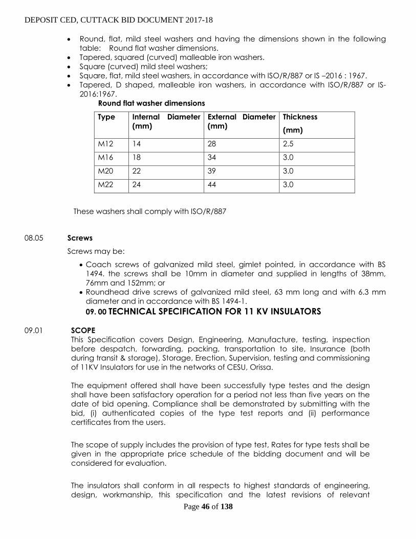
DEPOSIT CED, CUTTACK BID DOCUMENT 2017-18
Page 46 of 138
Round, flat, mild steel washers and having the dimensions shown in the following
table: Round flat washer dimensions.
Tapered, squared (curved) malleable iron washers.
Square (curved) mild steel washers;
Square, flat, mild steel washers, in accordance with ISO/R/887 or IS –2016 : 1967.
Tapered, D shaped, malleable iron washers, in accordance with ISO/R/887 or IS-
2016:1967.
Round flat washer dimensions
Type Internal Diameter
(mm)
External Diameter
(mm)
Thickness
(mm)
M12 14 28 2.5
M16 18 34 3.0
M20 22 39 3.0
M22 24 44 3.0
These washers shall comply with ISO/R/887
08.05 Screws
Screws may be:
Coach screws of galvanized mild steel, gimlet pointed, in accordance with BS
1494. the screws shall be 10mm in diameter and supplied in lengths of 38mm,
76mm and 152mm; or
Roundhead drive screws of galvanized mild steel, 63 mm long and with 6.3 mm
diameter and in accordance with BS 1494-1.
09. 00 TECHNICAL SPECIFICATION FOR 11 KV INSULATORS
09.01 SCOPE
This Specification covers Design, Engineering, Manufacture, testing, inspection
before despatch, forwarding, packing, transportation to site, Insurance (both
during transit & storage), Storage, Erection, Supervision, testing and commissioning
of 11KV Insulators for use in the networks of CESU, Orissa.
The equipment offered shall have been successfully type testes and the design
shall have been satisfactory operation for a period not less than five years on the
date of bid opening. Compliance shall be demonstrated by submitting with the
bid, (i) authenticated copies of the type test reports and (ii) performance
certificates from the users.
The scope of supply includes the provision of type test, Rates for type tests shall be
given in the appropriate price schedule of the bidding document and will be
considered for evaluation.
The insulators shall conform in all respects to highest standards of engineering,
design, workmanship, this specification and the latest revisions of relevant

DEPOSIT CED, CUTTACK BID DOCUMENT 2017-18
Page 47 of 138
standards at the time of offer.
Any departure from the provisions of this specification shall be disclosed in the Non
Compliance Schedule at the time of bidding.
09.02 STANDARDS
Except where modified by the specification, the Insulators shall be designed,
manufactured and tested in accordance with the latest editions of the following
standards.
IEC/ISO/BS IS Subject
IEC 120 Dimensions of ball and socket coupling of string
insulator units.
IEC 372 (1984) Locking devices for ball and socket couplings of
string insulator units : Dimensions and tests.
IEC 720 Characteristics of the line post insulators
IEC 383 Insulators for overhead lines with a nominal
voltage above 1000V.
IS- 731 Porcelain insulators for overhead power lines
IS –2486
(Part I, II,
III)
Specification for insulator fittings for overhead
power lines with a nominal voltage greater than
1000V.
IEC 273 Characteristics of indoor and outdoor insulators.
IS – 2544 Porcelain post insulators
IEC 168 Tests on post insulators
IEC 575 Thermal-mechanical performance test and
mechanical performance test on string insulator
units.
IEC 575 Thermal-mechanical performance test and
mechanical performance test on string insulator
units
IS-1445 Porcelain insulators for LV overhead power lines
IS- 5300 Stay insulators
ISO 8501-1 Shot blasting
IS –6005 Phosphating of iron and steel

DEPOSIT CED, CUTTACK BID DOCUMENT 2017-18
Page 48 of 138
IS-2633 Tests on galvanized steel
ISO 1460 IS – 2629 Hot dip galvanizing
IEC 1109 Composite Insulators
IEC 305 Characteristics of string insulators of the cap and
pin type.
IEC 471 Dimensions of clevis and tongue coupling of
string insulator units.
ISO 1460
BS 729
IS 2629 Specification for hot dip galvanized coatings on
iron and steel articles.
This list is not be considered exhaustive and reference to a particular standard or
recommendation in this specification does not relieve the Contractor of the necessity of
providing the goods complying with other relevant standards or recommendations.
TECHNICAL
The types of insulators described in this specification are intended to maintain the
general look of the existing network and to take advantage of the familiarity of the
employer’s staff with these type of units. However, the Bidder, is free to make
alternative proposals.
It shall be the Bidders responsibility to ensure that the insulators conform to or
exceed both the mechanical electrical properties specified in this specification and
all related international and Indian Standards.
The strength of the proposed insulators shall be capable of supporting the loads
generated as per the Bidder’s line design, by wind acting on the conductors and
insulators, by conductor tensions for maximum windspan and worst design
conditions and for all insulator duties and permitted line deviations.
09.03 PIN INSULATORS
09.04 Performance Characteristics
The insulators shall be suitable for use on the CESU distribution system with conditions as
shown in the sections on Service Conditions and System Conditions.
They shall conform to IEC 720 or IS 731 and shall meet the following performance criteria
Nominal Voltage 11 KV
Visible discharge voltage 9 KV rms.
Wet power frequency one minute withstand
voltage
35 KV rms.
Power frequency puncture voltage 105 KV rms.
Impulse withstand voltage peak 75 KV peak
Creepage distance 320 mm
Protected creepage distance --
Minimum failing load up to conductor size 100
mm2
11 KV
DEPOSIT CED, CUTTACK BID DOCUMENT 2017-18
Page 49 of 138
09.05 Materials
The insulators used by the Employer at present are of the brown glazed porcelain type.
Porcelain in the line pin insulators shall be sound, free from cavities and other defect,
thoroughly verified with uniform brown glaze and have a high quality smooth finish. The
glaze shall cover all the external parts of the insulator. The cement used shall not give
rise to chemical reaction with metal fittings.
09.06 Design and Construction
The relevant vertical dimension shall be such that when combined with pin
insulator spindle describe in technical specification for line fittings, the design
requirements are the specified voltage level for conductor clearance from the
cross arm shall be met.
The design shall be such that stresses due to expansion and contraction in any
part of the insulator shall not lead to deterioration. Precautions shall be taken to
avoid chemical reaction between cement and metal fittings by the choice of
suitable materials or by the manufacturing method. Single piece insulator
construction is preferred.
The insulating material shall not engage directly with hard metal. Pin insulators
shall be provided with a thimble of suitable material. Cement used in the
insulator shall not cause fracture by expansion or loosening by contraction and
proper care shall be taken to locate the individual parts correctly during
cementing. The insulators shall have a center conductor groove.
09.07 Markings
All insulators shall be clearly marked with the name or trademark of the
manufacturer, the minimum failing load in KN and the month and year of
manufacture. These marking shall be legible and indelible. The markings may be
printed or impressed, provided such impressions do not impair the performance
of the insulator. Markings shall be applied before firing.
10.00 STAY INSULATORS (11 KV)
The insulators shall be suitable for use on the CESU distribution system with conditions as
shown in the sections on Service Conditions and System Conditions 11 KV Stay insulators
shall be used on L.V stays.
10.01 Performance Characteristic shall be strictly as per relevant IS.
10.02 Materials The insulators shall be brown glazed porcelain .
10.03 Design

DEPOSIT CED, CUTTACK BID DOCUMENT 2017-18
Page 50 of 138
The bidder shall guarantee than the dimensions and tolerance of the insulators
offered are in accordance with the drawing which shall accompany the bid
documents.
The insulators shall be used with 7/8 SWG (7/4.00 mm ) steel stay wire, having an
overall diameter of 12.2 mm and tensile strength of 70 kgf/sq. mm. The insulators
shall be suitable for use having a minimum stay wire hole diameter of 22 mm and
be such that a straight stay wire can be passed through it.
10.04 Markings
All insulators shall be clearly marked with the name or trademark of the
manufacturer and the year of manufacture. These markings shall be legible and
indelible. The markings may be printed or impressed, provided such impressions do
not impair the performance of the insulator. Marking shall be applied before firing.
11.00 TECHNICAL SPECIFICATION FOR 11 KV LINE FITTINGS
11.01 SCOPE
This Specification covers Design, Engineering, Manufacture, testing, inspection
before despatch, forwarding, packing, transportation to site, Insurance (both
during transit & storage), Storage, Erection, Supervision, testing and
commissioning of 11KV Line Fittings for use in the networks of CESU, Orissa.
The equipment offered shall have been successfully type tested and the design
shall have been in satisfactory operation for a period not less than two years on
the date of bid opening. Fittings which are components of insulator assemblies
shall have been in satisfactory operation for a period not less than five years.
Examples of such fittings are spindles for pin insulators, and hooks, conductor
clamps, armour rods, and yoke plates for strain and suspension disc insulators.
Compliance shall be demonstrated by submitting with the bid (i) authenticated
copies of the type test reports and (ii) performance certificates from the users.
The scope of supply includes the provision of type tests. Rates for type tests shall
be given in the appropriate price schedule of the bidding document and will be
considered for evaluation.
The line fittings shall conform in all respects to highest standards of engineering,
design, workmanship, this specification and the latest revisions of relevant
standards at the time of offer.
11.02 STANDARDS
Except where modified by the specification, the fittings shall be designed,
manufactured and tested in accordance with the latest editions of the following
standards.
IEC/ISO/ or other
International
Standard
IS Title
IS-2486 Metal fittings of insulators

DEPOSIT CED, CUTTACK BID DOCUMENT 2017-18
Page 51 of 138
ISO/R/630/1967 IS-2062:1992 Steel for general structural purposes
ISO 2092 –1/2 IS-5082 :1981 Wrought aluminium and and aluminium
alloys
DIN 6796 Conical washers
IEC 1284
IS-2121 Overhead power line fittings
BS 3288
Insulator and Conductor fittings
performance
IEC 1089
IS –398 Aluminium conductors
IEC 502
Insulated power cables 1 –33 KV
ASTM D1000
IEC 454
Test methods of pressure sensitive,
adhesive coated taps for electrical and
electronic applications
BS 183
General purpose Galvanised Steel Wire
BS 4429
Turnbuckles for general engineering
purposes
BS EN 10218-1 :
1994
Mechanical tests on steel wire
ISO 9000
Quality Management Systems
ISO 8501-1
Shot blasting
IS –6005 Phosphating of iron and steel
ISO 1460 IS –2629 Hot dip galvanizing
IS- 2633 Galvanised steel tests
BS 1924 Tests on materials before stabilization
ISO 68, 261, 262,
724, 965/1, 965/3,
BS- 3643
Metric screw threads
BS 1387 Screwed and Socketed steel tubes
IS –2141 Hot dip galvanized stay strand
This list is not be considered exhaustive and reference to a particular standard or

DEPOSIT CED, CUTTACK BID DOCUMENT 2017-18
Page 52 of 138
recommendation in this specification does not relieve the Contractor of the
necessity of providing the goods complying with other relevant standards or
recommendations.
GENERAL
11.03 This specification covers the design, manufacture, testing, supply, delivery and
performance requirements of insulator fittings / hardware, conductor splices,
terminating connectors, binding and stay wire materials as required by the lines.
The dimensions and characteristics given in this specification are intended to
described typical distribution overhead line fittings and hardware which will
maintain the general look of the existing network and will take advantage of the
availability of tools and the familiarity of the employers staff with these kind of
arrangements.
However, the bidder is free to propose alternative fittings and hardware
provided the bid respects the general requirements of this specification.
Furthermore, it will be the bidder’s responsibility to ensure that all the fittings,
hardware and accessories are capable of supporting the mechanical and
electrical loads imposed on them by climatic conditions, conductor tensions
and structure loads under worst design conditions as stated in the specification.
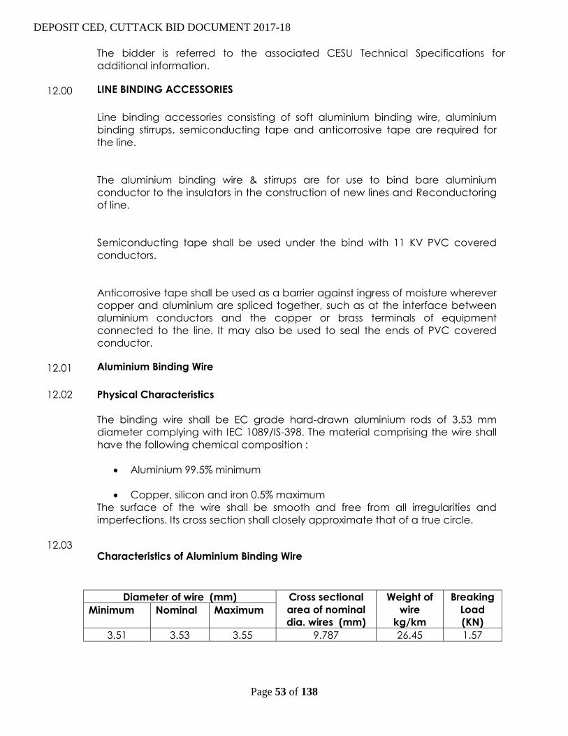
DEPOSIT CED, CUTTACK BID DOCUMENT 2017-18
Page 53 of 138
The bidder is referred to the associated CESU Technical Specifications for
additional information.
12.00 LINE BINDING ACCESSORIES
Line binding accessories consisting of soft aluminium binding wire, aluminium
binding stirrups, semiconducting tape and anticorrosive tape are required for
the line.
The aluminium binding wire & stirrups are for use to bind bare aluminium
conductor to the insulators in the construction of new lines and Reconductoring
of line.
Semiconducting tape shall be used under the bind with 11 KV PVC covered
conductors.
Anticorrosive tape shall be used as a barrier against ingress of moisture wherever
copper and aluminium are spliced together, such as at the interface between
aluminium conductors and the copper or brass terminals of equipment
connected to the line. It may also be used to seal the ends of PVC covered
conductor.
12.01 Aluminium Binding Wire
12.02 Physical Characteristics
The binding wire shall be EC grade hard-drawn aluminium rods of 3.53 mm
diameter complying with IEC 1089/IS-398. The material comprising the wire shall
have the following chemical composition :
Aluminium 99.5% minimum
Copper, silicon and iron 0.5% maximum
The surface of the wire shall be smooth and free from all irregularities and
imperfections. Its cross section shall closely approximate that of a true circle.
12.03 Characteristics of Aluminium Binding Wire
Diameter of wire (mm) Cross sectional
area of nominal
dia. wires (mm)
Weight of
wire
kg/km
Breaking
Load
(KN) Minimum Nominal Maximum
3.51 3.53 3.55 9.787 26.45 1.57

DEPOSIT CED, CUTTACK BID DOCUMENT 2017-18
Page 54 of 138
Physical properties
The surface of the finished wire shall be checked to ensure that it is smooth, free
from all irregularities, imperfections and inclusions and that its cross section
approximates closely that of a true circle.
The wire shall be checked to ensure that its diameter and weight are within the
values given in the table above : Characteristics of aluminium binding wire.
Ultimate tensile strength
When tested on a standard tensile testing machine, the value obtained for the
ultimate tensile stress shall not be less than 1.57 KN.
Wrapping test
The wire shall withstand one cycle of a wrapping test as follows :
The wire shall be closely wrapped round a wire of its own diameter to form a
close helix of eight turns. Six turns shall then be unwrapped and again closely
rewrapped in the same direction as the first wrapping. The wire shall not break or
crack when subjected to this test.
12.04 Aluminium Binding Straps
12.05 Physical Characteristics
The following types shall be required :
Intermediate pole binding stirrups for 33 KV and 11 KV; and
Light angle pole binding stirrups for 33 KV and 11 KV.
It shall be the responsibility of the bidder to ensure that the stirrups match the
insulators.
Each aluminium stirrup shall be made of a 7 mm diameter aluminium rod
complying with ISO 209-1/2.
The tensile strength of the stirrups shall be between 135N/mm2 and 170 N/mm2

DEPOSIT CED, CUTTACK BID DOCUMENT 2017-18
Page 55 of 138
12.06 Fabrication
Stirrups shall be cold formed on a suitable mandrel such that the bends are
smooth and the surfaces free from indentations.
The stirrups for intermediate positions shall be formed through the following steps:
The U shape shall be formed first around a mandrel of the appropriate
diameter;
The 900 bend in one plane and 450 bend in the other plane shall then be
formed simultaneously with the ends of the rod free. This is to ensure that
torsion stresses are not induced in the material during this formaing
operation; and
The legs shall then be formed through 450 and finally the ends of the
stirrup shall be bent through 900.
12.07 Semiconducting Tape
12.08 Physical and Other Characteristics
The semiconduting tape shall be used to relieve 11 KV PVC covered conductor
from electrical stress at insulator positions.
This tape shall be a soft, semiconducting, ethylene propylene rubber based,
high voltage tape, used for binding 11 KV PVC covered conductor.
The semiconducting tape shall be non vulcanizing stable at temperatures upto
1300 C, highly resistant to cracking, moisture and ultra violet radiation,
unaffected by vibration and compatible with hydrocarbon and chlorinated
solvents.
In addition, it shall be a semiconducting, self amalgamating tape, highly
conformable to irregular shapes and compatible with solid dielectric cable
insulation.
Specifically, the type offered shall be suitable for use with the 11 KV PVC
covered conductors : AAA conductors and it shall comply with IEC 502 or
equivalent.
The tape shall be indelibly and legibly marked along its length with a suitable
legend, such as, “caution: semiconducting”. The tape shall be suitable for
outdoor locations exposed to severe climatic conditions including ultraviolet
rays, rain and wind. The tape shall have the characteristics shown in the
following table.
Characteristics Characteristic Value
Physical
Thickness 0.75 mm

DEPOSIT CED, CUTTACK BID DOCUMENT 2017-18
Page 56 of 138
Tensile strength 1.00 kg/cm2
Elongation 800 %
Normal conditions temperature 900 C
Emergency conditions temperature 1300 C
Electrical
Ac resistivity 750 ohm-cm
Dc resistivity 750 ohm –cm
Maximum capacity 5 mA
In addition, all these tapes shall be ozone resistant (even when stretched 500%), they
shall be resistant to ultraviolet radiation and they shall be compatible with ketones and
hydrocarbon and chlorinated solvents.
13.00 Anticorrosive Tape
This tape shall be used to protect bimetal connections from the ingress of moisture
and to seal the ends of PVC covered conductor. Therefore, the anticorrosive tape
offered shall retain its composition and plasticity over a wise temperature range.
The anticorrosive tape shall be non cracking and non hardening and shall not be
affected by vibration. The tape shall be highly impermeable to water and highly
resistant to mineral acids, alkalis and salts.
In general, the anticorrosive tape offered shall comply with IEC 454 or equivalent.
13.01 Markings
The tape cores shall be marked with :i) the manufacturer’s name or trademark ;
and ii) the product reference.
Weight of wire in kilograms.
14.00 Pole Brackets for Stay
The pole bracket shall be made of mild steel to grade 43A conforming to ISO/R/
630/1967 or IS –2062:1992 and galvanized in accordance with the section on
Surface Treatment in this specification. Pole brackets shall be suitable for use on
steel or concrete poles. The minimum strength of the bracket shall be equal to the
design breaking load of the stay wire.
All bolts, nuts an washers shall be supplied with the stay assemblies, and shall
conform to the requirements. Bolts shall have a metric thread and a 20 mm
diameter.
15.00 SPARE PARTS AND SPECIAL TOOLS

DEPOSIT CED, CUTTACK BID DOCUMENT 2017-18
Page 57 of 138
The Bidder shall provide a list of recommended spare parts, special erection and
installation tools/ equipment together with their individual prices. This list shall identify all
essential spares items for any recommended maintenance for a period of five years
after commissioning.
The Project Manager may order all or any of the spare parts/erection/ installation tools
listed at the time of contract award and the parts so ordered shall be supplied as part
of the definite works. The Project Manager may order additional spares at any time
during the contract period at the rates stated in the Contract Document.
A spare parts catalogue with price list shall be provided and this shall form part of the
drawings and literature to be supplied.
The Bidder shall give an assurance that spare parts and consumable items will continue
to be available through the life of the equipment, which shall be 25 years minimum.
However, the Contractor shall give a minimum of 12 months notice in the event that the
Contractor or any sub-contractors plan to discontinue manufacture of any component
used in this equipment.
Any spare apparatus, parts or tools shall be subject to the same specification, tests and
conditions as similar material supplied under the Contract. They shall be strictly
interchangeable and suitable for use in place of the corresponding parts supplied with
the plant and must be suitably marked and numbered for identification.
Spare parts shall be delivered suitably packed and treated for long periods in storage.
Each pack shall be clearly and indelibly marked with its contents, including a
designation number corresponding to the spare parts list in the operation and
maintenance instructions.
16.00 TECHNICAL SPCIFICATION FOR 11 KV 400AMPS 3 POLE AB SWITCH FOR TRANSFORMER
GUARANTEED TECHNICAL PARTICULARS
Sl.No Particulars 11 KV 400 Amps A.B.
Switches ( desired value)
16.01 Type of Switch Rotating type only
16.02 Suitable for mounting Horizontal only
16.03 Number of supporting post insulator
per phase
2 nos. 12 KV Post
Insulator per phase as
per ISS-2544/1973.
16.04 Post Insulator.
A Type of cemeting To be quoted original
cemented only & as per
ISS-2544/1973 & relevant
IEC
B One minute power frequency
withstand voltage Dry
35 KV RMS.
C One minute power frequency
withstand voltage Wet.
35 KV RMS.
D Visible discharge voltage 9 KV RMS.
E Power frequency puncture withstand
voltage flash over voltage
1.3 times of actual dry
flash over voltage
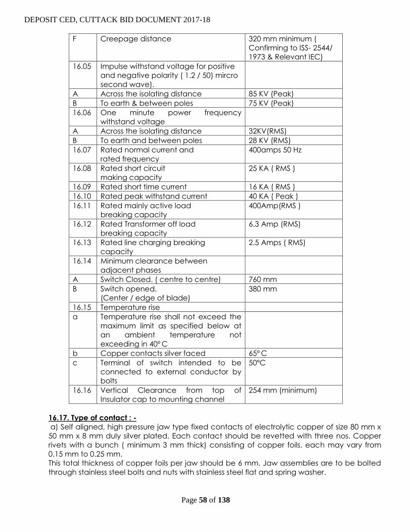
DEPOSIT CED, CUTTACK BID DOCUMENT 2017-18
Page 58 of 138
F Creepage distance 320 mm minimum (
Confirming to ISS- 2544/
1973 & Relevant IEC)
16.05 Impulse withstand voltage for positive
and negative polarity ( 1.2 / 50) mircro
second wave).
A Across the isolating distance 85 KV (Peak)
B To earth & between poles 75 KV (Peak)
16.06 One minute power frequency
withstand voltage
A Across the isolating distance 32KV(RMS)
B To earth and between poles 28 KV (RMS)
16.07 Rated normal current and
rated frequency
400amps 50 Hz
16.08 Rated short circuit
making capacity
25 KA ( RMS )
16.09 Rated short time current 16 KA ( RMS )
16.10 Rated peak withstand current 40 KA ( Peak )
16.11 Rated mainly active load
breaking capacity
400Amp(RMS )
16.12 Rated Transformer off load
breaking capacity
6.3 Amp (RMS)
16.13 Rated line charging breaking
capacity
2.5 Amps ( RMS)
16.14 Minimum clearance between
adjacent phases
A Switch Closed. ( centre to centre) 760 mm
B Switch opened.
(Center / edge of blade)
380 mm
16.15 Temperature rise
a Temperature rise shall not exceed the
maximum limit as specified below at
an ambient temperature not
exceeding in 40º C
b Copper contacts silver faced 65º C
c Terminal of switch intended to be
connected to external conductor by
bolts
50ºC
16.16 Vertical Clearance from top of
Insulator cap to mounting channel
254 mm (minimum)
16.17. Type of contact : -
a) Self aligned, high pressure jaw type fixed contacts of electrolytic copper of size 80 mm x
50 mm x 8 mm duly silver plated. Each contact should be revetted with three nos. Copper
rivets with a bunch ( minimum 3 mm thick) consisting of copper foils, each may vary from
0.15 mm to 0.25 mm.
This total thickness of copper foils per jaw should be 6 mm. Jaw assemblies are to be bolted
through stainless steel bolts and nuts with stainless steel flat and spring washer.

DEPOSIT CED, CUTTACK BID DOCUMENT 2017-18
Page 59 of 138
b) Solid rectangular blade type moving contact of electrolytic copper size 220 mm x 50 mm
x 8 mm duly silver plated ensuring a minimum deposit of 10 micron of silver on copper
contacts or as may be prescribed under relevant ISS / IEC.
c) Pressure spring to be used in jaw contacts shall be Stainless Steel having 8 nos of turn
x 28 mm height x 14.4 mm diameter with 14 SWG wire (minimum six nos springs shall be used)
16.18.Connectors : -
Terminal connectors for both movable and fixed should be of copper flats of same size
similar to that of moving contact blades ( minimum 95 % copper composition). The fixed
connector shall of size 80 mm x 50 x 8 mm and the size of movable connector shall be size 80
x 50 x 8 mm with machine finishing duly silver plated with 2 nos. of 3/8” stainless steel bolts ,
nuts , plain washers & spring washers should be provided along with 2 nos solder less
bimetallic sockets for each connector suitable sockets for each connector suitable up to 80
Sq.
16.19. Moving Contact:
Movable contact is to be supported by galvanized angle of 50 x 50 x 5 mm in each phase
and the moving contact are to be bolted through 2 nos stainless steel bolts and nuts with
suitable stainless steel flat and spring washers.
16.20. Galvanization
a) Iron parts shall be dip galvanised as per IS-2633 / 1972.
b) The pipe shall be galvanised as per IS-4736 / 1968.
16.21. Details of Phase
(a) Coupling Rod 25 mm nominal bore G.I. pipe medium guage.
(b) Operating Rod 32 mm nominal bore G.I. pipe medium gauge single length 6 mtrs.
The detailed dimension of the G. I. pipe as per IS-1239 (Pt. I are mentioned below :-
Nominal Base Outside diameter Diameter thickness
Max. Min
25mm. 34.2mm. 33.3mm. 3.25mm.
32mm. 42.9mm. 42mm. 3.25mm.
c) Arcing Horn 10 mm dia G.I. Rod with spring assisted operation.
d) Force of fixed contact spring:- 50lbs to 75lbs.
e) Copper braided flexible topes : -
320 mm length of flexible electrolytic copper tape or braided chord (with tin coated) having
minimum weight 450 gms per meter and both ends shall be crimped with copper sockets
through brass bolts and nuts with brass flat washers. Two nos of suitable copper sockets shall
be used at bothe ends. The minimum no. of flexible wires should be 1536 of 36 SWG for each
flexible chord
f) Quick break device Lever mechanism
g) Bearings 4 nos. self lubricated bearing to be provided with
grease nipple including 4 th bearing being a thrust
bearing.
h) Locking arrangement Pad Locker & Key arrangement at both ‘ON’ & ‘OFF’ position
i) Earth Terminal To be provided at base channels.
16.22. Supporting Channels 75 mm x 40 mm M.S. Channel hot deep (galvanized)
17.00 TECHNICAL SPCIFICATION FOR 11 KV 200 AMPS 3 POLE AB SWITCH FOR TRANSFORMER
GUARANTEED TECHNICAL PARTICULARS
Sl.No Particulars 11 KV 200 Amps A.B.
Switches ( desired value)
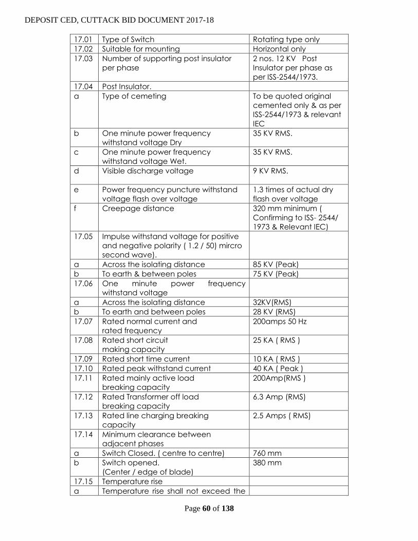
DEPOSIT CED, CUTTACK BID DOCUMENT 2017-18
Page 60 of 138
17.01 Type of Switch Rotating type only
17.02 Suitable for mounting Horizontal only
17.03 Number of supporting post insulator
per phase
2 nos. 12 KV Post
Insulator per phase as
per ISS-2544/1973.
17.04 Post Insulator.
a Type of cemeting To be quoted original
cemented only & as per
ISS-2544/1973 & relevant
IEC
b One minute power frequency
withstand voltage Dry
35 KV RMS.
c One minute power frequency
withstand voltage Wet.
35 KV RMS.
d Visible discharge voltage 9 KV RMS.
e Power frequency puncture withstand
voltage flash over voltage
1.3 times of actual dry
flash over voltage
f Creepage distance 320 mm minimum (
Confirming to ISS- 2544/
1973 & Relevant IEC)
17.05 Impulse withstand voltage for positive
and negative polarity ( 1.2 / 50) mircro
second wave).
a Across the isolating distance 85 KV (Peak)
b To earth & between poles 75 KV (Peak)
17.06 One minute power frequency
withstand voltage
a Across the isolating distance 32KV(RMS)
b To earth and between poles 28 KV (RMS)
17.07 Rated normal current and
rated frequency
200amps 50 Hz
17.08 Rated short circuit
making capacity
25 KA ( RMS )
17.09 Rated short time current 10 KA ( RMS )
17.10 Rated peak withstand current 40 KA ( Peak )
17.11 Rated mainly active load
breaking capacity
200Amp(RMS )
17.12 Rated Transformer off load
breaking capacity
6.3 Amp (RMS)
17.13 Rated line charging breaking
capacity
2.5 Amps ( RMS)
17.14 Minimum clearance between
adjacent phases
a Switch Closed. ( centre to centre) 760 mm
b Switch opened.
(Center / edge of blade)
380 mm
17.15 Temperature rise
a Temperature rise shall not exceed the

DEPOSIT CED, CUTTACK BID DOCUMENT 2017-18
Page 61 of 138
maximum limit as specified below at
an ambient temperature not
exceeding in 40º C
b Copper contacts silver faced 65º C
c Terminal of switch intended to be
connected to external conductor by
bolts
50ºC
17.16 Vertical Clearance from top of
Insulator cap to mounting channel
254 mm (minimum)
17.17. Type of contact : -
a) Self aligned, high pressure jaw type fixed contacts of electrolytic copper of size 65 mm x
35 mm x 6 mm duly silver plated. Each contact should be revetted with three nos. Copper
rivets with a bunch ( minimum 3 mm thick) consisting of copper foils, each may vary from
0.15 mm to 0.25 mm.
This total thickness of copper foils per jaw should be 6 mm. Jaw assemblies are to be bolted
through stainless steel bolts and nuts with stainless steel flat and spring washer.
b) Solid rectangular blade type moving contact of electrolytic copper size 220 mm x 35 mm
x 6 mm duly silver plated ensuring a minimum deposit of 10 micron of silver on copper
contacts or as may be prescribed under relevant ISS / IEC.
c) Pressure spring to be used in jaw contacts shall be Stainless Steel having 8 nos of turn
x 28 mm height x 14.4 mm diameter with 14 SWG wire (minimum six nos springs shall be used)
17.18.Connectors : -
Terminal connectors for both movable and fixed should be of copper flats of same size
similar to that of moving contact blades ( minimum 95 % copper composition). The fixed
connector shall of size 65 mm x 35 x 6 mm and the size of movable connector shall be size 65
x 35 x 6 mm with machine finishing duly silver plated with 2 nos. of 3/8” stainless steel bolts ,
nuts , plain washers & spring washers should be provided along with 2 nos solder less
bimetallic sockets for each connector suitable sockets for each connector suitable up to 50
Sq. mm.
17.19. Moving Contact:
Movable contact is to be supported by galvanized angle of 45 x 45 x 5 mm in each phase
and the moving contact are to be bolted through 2 nos stainless steel bolts and nuts with
suitable stainless steel flat and spring washers.
17.20. Galvanization
a) Iron parts shall be dip galvanised as per IS-2633 / 1972.
b) The pipe shall be galvanised as per IS-4736 / 1968.
17.21. Details of Phase
(a) Coupling Rod 25 mm nominal bore G.I. pipe medium guage.
(b) Operating Rod 32 mm nominal bore G.I. pipe medium gauge single length 6 mtrs.
The detailed dimension of the G. I. pipe as per IS-1239 (Pt. I are mentioned below :-
Nominal Base Outside diameter Diameter thickness
Max. Min
25mm. 34.2mm. 33.3mm. 3.25mm.
32mm. 42.9mm. 42mm. 3.25mm.
c) Arcing Horn 8 mm dia G.I. Rod with spring assisted operation.
d) Force of fixed contact spring:- 50lbs to 75lbs.

DEPOSIT CED, CUTTACK BID DOCUMENT 2017-18
Page 62 of 138
e) Copper braided flexible topes : -
320 mm length of flexible electrolytic copper tape or braided chord (with tin coated) having
minimum weight 450 gms per meter and both ends shall be crimped with copper sockets
through brass bolts and nuts with brass flat washers. Two nos of suitable copper sockets shall
be used at bothe ends. The minimum no. of flexible wires should be 1536 of 36 SWG for each
flexible chord
f) Quick break device Lever mechanism
g) Bearings 4 nos. self lubricated bearing to be provided with
grease nipple including 4 th bearing being a thrust
bearing.
h) Locking arrangement Pad Locker & Key arrangement at both ‘ON’ & ‘OFF’ position
i) Earth Terminal To be provided at base channels.
17.22. Supporting Channels 75 mm x 40 mm M.S. Channel hot deep (galvanized)
17.23N.B.( For All types of AB Switches ) : - i) Ferrous parts shall be duly galvanised as per
IS – 2633 / 1972 & Non-ferrous parts shall be silver plated.
18.00 TECHNICAL SPECIFICATION FOR 11 KV 200 AMP THREE POLE H.G. FUSE SETS FOR
DISTRIBUTION S/S.
18.01 SCOPE: - This specification covers the manufacture, testing and supply of 11 KV, 200
Amps 3 pole/Two pole, H.G. Fuse Sets.
18.02 (a) The 11 KV H.G. Fuses shall be suitable for out door operation in horizontal
configuration under the climatic conditions specified. It shall be of the following
ratings:-
1. Number of Poles 3
2. No. of insulator per pole 2 nos. 12 KV post insulators
3. Nominal system voltage 11 KV
4. Highest system voltage 12KV
5. Rated frequency 50 Hz
6. System Earthing Effectively earthed
7. Rated normal current 200 Amps
8. Altitude of installation Not exceeding 1000 M.
The post insulator used in the H.G. Fuse set shall have the following ratings:-
1. Power frequency withstand voltage (dry) 35KV (RMS)
2. Power frequency withstand voltage (wet) 35 KV (RMS)
3. Impulse withstand voltage (dry) 75 KV (Peak)
4. Power frequency puncture 1.3 times the actual dry
Withstand voltage flashover voltage of the
Unit.
18.03 (a) The 11 KV H.G. Fuses shall be suitable for out door operation in horizontal
configuration under the climatic conditions specified. It shall be of the following
ratings:-
1. Number of Poles 2
2. No. of insulator per pole 2 nos. 12 KV post insulators
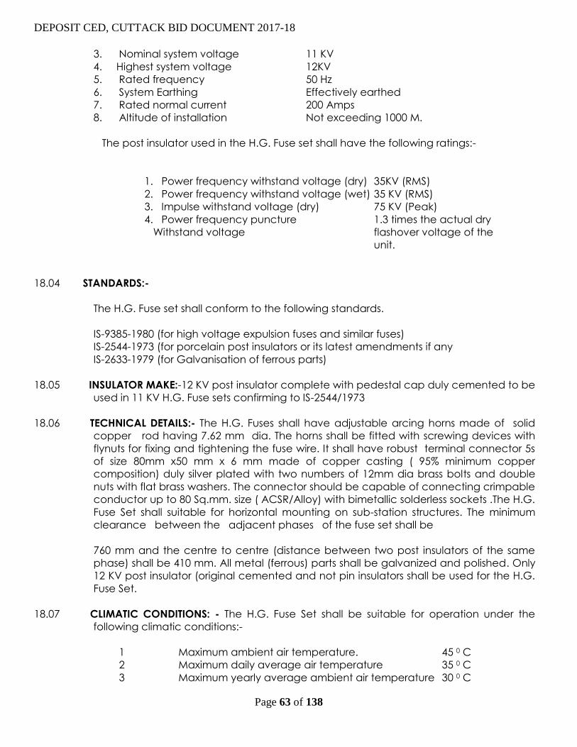
DEPOSIT CED, CUTTACK BID DOCUMENT 2017-18
Page 63 of 138
3. Nominal system voltage 11 KV
4. Highest system voltage 12KV
5. Rated frequency 50 Hz
6. System Earthing Effectively earthed
7. Rated normal current 200 Amps
8. Altitude of installation Not exceeding 1000 M.
The post insulator used in the H.G. Fuse set shall have the following ratings:-
1. Power frequency withstand voltage (dry) 35KV (RMS)
2. Power frequency withstand voltage (wet) 35 KV (RMS)
3. Impulse withstand voltage (dry) 75 KV (Peak)
4. Power frequency puncture 1.3 times the actual dry
Withstand voltage flashover voltage of the
unit.
18.04 STANDARDS:-
The H.G. Fuse set shall conform to the following standards.
IS-9385-1980 (for high voltage expulsion fuses and similar fuses)
IS-2544-1973 (for porcelain post insulators or its latest amendments if any
IS-2633-1979 (for Galvanisation of ferrous parts)
18.05 INSULATOR MAKE:-12 KV post insulator complete with pedestal cap duly cemented to be
used in 11 KV H.G. Fuse sets confirming to IS-2544/1973
18.06 TECHNICAL DETAILS:- The H.G. Fuses shall have adjustable arcing horns made of solid
copper rod having 7.62 mm dia. The horns shall be fitted with screwing devices with
flynuts for fixing and tightening the fuse wire. It shall have robust terminal connector 5s
of size 80mm x50 mm x 6 mm made of copper casting ( 95% minimum copper
composition) duly silver plated with two numbers of 12mm dia brass bolts and double
nuts with flat brass washers. The connector should be capable of connecting crimpable
conductor up to 80 Sq.mm. size ( ACSR/Alloy) with bimetallic solderless sockets .The H.G.
Fuse Set shall suitable for horizontal mounting on sub-station structures. The minimum
clearance between the adjacent phases of the fuse set shall be
760 mm and the centre to centre (distance between two post insulators of the same
phase) shall be 410 mm. All metal (ferrous) parts shall be galvanized and polished. Only
12 KV post insulator (original cemented and not pin insulators shall be used for the H.G.
Fuse Set.
18.07 CLIMATIC CONDITIONS: - The H.G. Fuse Set shall be suitable for operation under the
following climatic conditions:-
1 Maximum ambient air temperature. 45 0 C
2 Maximum daily average air temperature 35 0 C
3 Maximum yearly average ambient air temperature 30 0 C

DEPOSIT CED, CUTTACK BID DOCUMENT 2017-18
Page 64 of 138
4 Maximum temperature attainable by a body
Exposed to the sun.`` 50 0 C
5 Minimum ambient air temperature o 0 C
6. Maximum relative humidity. 100%
7. Average number of thunderstorm days per annum 70 days
8. Average number of rainy days per annum 120
9. Average annual rain fall. 150 cm.
10. Number of months of tropical monsoon conditions 4
11. Maximum wind pressure. 260 Kg./ mm2
12. Degree of exposure to atmospheric pollution. Normally polluted
atmosphere.
19.00 GALVANIZATION
All ferrous materials to be used are of hot dip galvanized of 610gm./ Mtr².
20.00 SPECIFICATION FOR 25 / 63 / 100 KVA L. T. DIST. BOX WITH INCOMING
WITH DISCONNECTOR SWITCH AND OUTGOING PORCELAIN FUSE UNITS)
20.01. SCOPE
The Specification covers design, manufacturing Factory testing and supply of L.T.
Distribution Boxes with Switch disconnector and Porcelain Fuse units for protection
and control of 25/63/100 KVA Distribution Transformers and LT line in rural areas and
as per IS No. 13947 (P. , 2, 3) of 1993 with latest amendment if any and also
other applicable IS Nos. mentioned in Specification.
20.02 The Distribution Box shall comprise of (1) suitable enclosure (factory built assembly)
fabricated from new CRC Steel Sheet (2) Porcelain Fuse units as per IS: 2086/1993
with latest amendment/ Revision if any on the date of inviting tender and as per CESU
specification. (3) Incoming Switch disconnector as per IS: 13947/1993 with latest
Amendment/Revision if any on the date of inviting tender.
20.03 GENERAL REQUIREMENT :
20.04 L. T. Distribution Box should be designed to have maximum utilization of transformer
capacity and shall be well equipped with adequate protection to transformer and
feeder against overload and short circuit and minimum interruption in power supply.
20.05. SERVICE CONDITION :-
a) TEMPERATURE :
The materials used in Construction of the Distribution Box shall be suitable for use
under following conditions.
(a) Maximum ambient temperature 55º C
(b) Maximum daily average ambient temperature 37º C
(c) Minimum temperature 0º C
(d) Altitude 0 to 1000 meter.
(e) Maximum yearly average air temp. 35º C
b) RELATIVE HUMIDITY :-
This does not exceed 50% of maximum temperature of 40 º C and 90 % at 20º C care
shall be taken for moderate condensation which may occasionally occur due to variation
in temperature. Even on sea shore side having heavy pollution the box should function
satisfactorily.
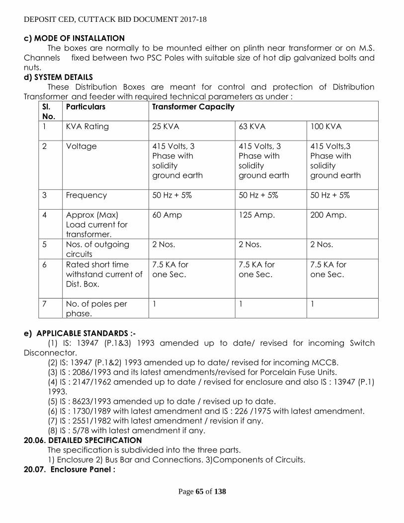
DEPOSIT CED, CUTTACK BID DOCUMENT 2017-18
Page 65 of 138
c) MODE OF INSTALLATION
The boxes are normally to be mounted either on plinth near transformer or on M.S.
Channels fixed between two PSC Poles with suitable size of hot dip galvanized bolts and
nuts.
d) SYSTEM DETAILS
These Distribution Boxes are meant for control and protection of Distribution
Transformer and feeder with required technical parameters as under :
Sl.
No.
Particulars Transformer Capacity
1 KVA Rating 25 KVA 63 KVA
100 KVA
2 Voltage 415 Volts, 3
Phase with
solidity
ground earth
415 Volts, 3
Phase with
solidity
ground earth
415 Volts,3
Phase with
solidity
ground earth
3 Frequency 50 Hz + 5% 50 Hz + 5% 50 Hz + 5%
4 Approx (Max)
Load current for
transformer.
60 Amp 125 Amp. 200 Amp.
5 Nos. of outgoing
circuits
2 Nos. 2 Nos. 2 Nos.
6 Rated short time
withstand current of
Dist. Box.
7.5 KA for
one Sec.
7.5 KA for
one Sec.
7.5 KA for
one Sec.
7 No. of poles per
phase.
1 1
1
e) APPLICABLE STANDARDS :-
(1) IS: 13947 (P.1&3) 1993 amended up to date/ revised for incoming Switch
Disconnector.
(2) IS: 13947 (P.1&2) 1993 amended up to date/ revised for incoming MCCB.
(3) IS : 2086/1993 and its latest amendments/revised for Porcelain Fuse Units.
(4) IS : 2147/1962 amended up to date / revised for enclosure and also IS : 13947 (P.1)
1993.
(5) IS : 8623/1993 amended up to date / revised up to date.
(6) IS : 1730/1989 with latest amendment and IS : 226 /1975 with latest amendment.
(7) IS : 2551/1982 with latest amendment / revision if any.
(8) IS : 5/78 with latest amendment if any.
20.06. DETAILED SPECIFICATION
The specification is subdivided into the three parts.
1) Enclosure 2) Bus Bar and Connections. 3)Components of Circuits.
20.07. Enclosure Panel :

DEPOSIT CED, CUTTACK BID DOCUMENT 2017-18
Page 66 of 138
a) The box shall be suitable for outdoor installation as per attached reference
Drawing.
The box is expected to be mounted below the transformers and it shall be mounted
on PSC/ Girder poles or on Plinth as the case may be.
b) The thickness of CRC Steel Sheet be of 1.6 mm. Thickness (before painting) i.e. 16
gauge + tolerance as per IS.
c) Maximum portion of the box shall be made by folding same new CRC sheet to
minimize welded joints.
d) Door hinge shall be properly welded to box and cover; The box shall open at side
i.e. horizontal opening. Swing of door opening be minimum 90º. Hinges shall be provided
from inside only. The arrangement of door shall be as per drawing (Face to face).
e) The door locking device similar to that of “Godrej” type three way locking
arrangement shall be provided. In addition to this, Padlocking arrangement be also
provided at center.
f) Two sets of M.S. Clamps .Duly hot dip galvanized be supplied.
g) Durable gasket shall be provided around the boxes to prevent outside dust
entering inside and to have proper vermin proofing. The rubber lining should be
minimum 3 mm thick. The lining should be irremovable from the groove.
h) The roof should be given a slope of 5 o to 15 o to drain the rainwater easily.
i ) Two sets of louvers shall be provided on the side walls (as shown in drawing) The
louvers shall be backed up by perforated stainless steel sheets of 0.5 mm. thickness
welded from inside the box for preventing dust, insects and rain water getting inside
the box. As such box will be provided with IP- 44 protection and entry of fresh cool air
and to maintain the temperature rise limits of various components provided inside the
box as per IS.
j) The current carrying parts should be properly connected using nonmagnetic
stainless steel bolts, nuts & washers. The nuts and bolts should be of hexagonal type
with groove for bolt. All other bolts, nuts and plain washers used for tightening purpose
including connectors should be of M.S. hot dip galvanized. Bolts, nuts washers also shall
be hot dip galvanized. “For fasteners below 16 mm size same may be electroplated.”
k) The overall dimensions of the box in the tender drawing is for reference only,
however internal clearance shown in the drawing shall be strictly maintained. Over all
dimensions of the box shall be such that the box will withstand temperature rise limits as
per IS and Company’s Specification. There should be sufficient space for working during
maintenance. The size of the box will depend on the size of disconnector switch and
Porcelain fuses to be provided and other relevant provision made in
IS:13947/(P1,2&3)/1993, IS 2086/1993 and IS:4237/1983 with latest amendment if
any. The box will fulfill following requirement..
i) The enameled danger notice plate as per IS: 2551 /1982 of size 200x150mm
shall be riveted in pilfer proof manner on front cover of the box.
ii) The incoming and outgoing terminals of the, Disconnector Porcelain Fuses
and the bus bars shall have suitable termination Disconnector and Porcelain
Fuses should have extended terminals for proper clearance to be maintained
between phases.

DEPOSIT CED, CUTTACK BID DOCUMENT 2017-18
Page 67 of 138
iii) All other minimum clearance between phases, between phase and earth
shall be as per minimum requirement of IS; 13947 (P1, 2&3) 1993 and as
mentioned in drawing.
iv) The temperature rise shall be within limits specified in IS: 13947/(P1, 2&3) /
1993 and also mentioned at Annexure- “A” with specification. The test
certificate from Government approved and NABL accredited Laboratory such
as CPRI, NPL, ETDC, ERDA, ERTL etc. for the same should be submitted, which
shall not be more than five years old from the date of the tender.
v) Separate half round clamps of 2 mm MS sheet should be provided for
holding the incoming & outgoing cables, so that cables do not rest directly on
the terminals.
vi) Number plate containing following details shall be riveted inside the door of
the L.T. Dist. Box and also outside on front side name of the firm as well as CESU
should be embossed with manufacturing year.
1) Company’s Name with full address
2) Capacity of Box
3) Serial No. of Box
4) A/T No. with date
5)Property of CESU
6)Date of supply of L.T. Dist. Box
20.08. SURFACE TREATMENT
All sheet metal work shall undergo 7 tank chemical & mechanical cleaning process
and thereafter two coats of red oxide and two coats of final weatherproof & corrosion
resistance enamel paint shall be applied by powder coating process only. The colour of
paint inside shall be same as specified for outside of Dist. Box.
a) The facility for painting including the 7 tank cleaning process shall be in house to
ensure proper quality since these panels are for outdoor applications wherein
continuous changes in climatic conditions is common phenomena.
b) Final paint from inside and outside shall be enamel light gray.
c) All other metal parts used in the distribution boxes shall be treated as under:
M.S. Parts: All MS. Parts should be hot dip galvanized with min.
thickness of galvanize coating should be 80
microns.
Base plates: Zinc Plating.
Bus bars and connections: with heat shrinkable color coded insulating sleeves
indicating R,Y, B phase.
20.09. NEUTRAL:-
A solid neutral link of aluminum shall be provided for terminating neutral core of
incoming and outgoing cables directly. The neutral shall be duly supported on
insulating supports and aluminum lugs with suitable washer will be provided for
connections. Cross sectional area of neutral link shall be 50% of main bus bar current
capacity. Neutral bus bar shall withstand rated short time current for one sec as per IS
8623/93 with latest amendment.
20.10 CABLE TERMINATION:-

DEPOSIT CED, CUTTACK BID DOCUMENT 2017-18
Page 68 of 138
a) For connecting internal circuit i.e. incoming and outgoing connections, the
suitable size of aluminum bus bar of sufficient capacity to meet the required ampere
loading for the box. The
calculation of bus bar size for Amp. loading is to be provided in the bid for reference.
b) Incoming cables shall enter from the side portion of the box just parallel to the
terminals of the installed isolator switch and outgoing cable shall enter of the welded
bottom plates with separate gland plate having minimum size of 100 x 100 mm and
having suitable knock out / drilled holes suitable for cable sizes as specified in the
drawing. The separate gland plate shall be fitted with the proper size of hardware.
The size of cable to be used are as under:-
1 KVA Rating 25 63 100
2 Incoming Cable size
mm²
35 95/120/ 150 150/ 185
3 Outgoing Cable size
mm²
35/50 70/50 50/95/70
4 Numbers of circuits 2 2 2
c) All the three terminals of Disconnector shall be extended by suitable aluminum
strips.
d) Adequate cabling space shall be provided in the box for incoming and outgoing
cables.
e) PVC type glands shall be provided for incoming and outgoing cables. The
compression type gland shall be having grooved rubber ring of appropriate
diameter.
20.11 Bus bars & Connectors:
a) Aluminum bus bar shall be used for Kit Kat fuse connections .
b) Current capacity of Aluminum bus bars shall be adequate to met the requirement
as per IS.
c) Aluminum bus bars and links should be properly drilled, debarred and bolted to
minimize heating of joints.
d) Bus bars shall be covered with color coated heat shrinkable Insulating sleeve with
R,Y,B coding.
e) Approximate Bus bar size should be for 25 KVA 3x25 mm, for 63/100 KVA 6x25mm
or 5x30mm and size of neutral bus for 25 KVA 3 x 12mm and for 63/100 KVA 6 x 12mm.
20.12. COMPONENTS OF CIRCUITS
20.12.01 INCOMING CIRCUIT:
Each distribution box shall have one triple pole Switch Disconnector. The rating and
other technical parameters of incoming Switch Disconnector shall be as
Sr.
No.
CHARACTERSTICS 25 KVA/63KVA 100KVA
1 Basic Rating 100/200 Amps. 250 Amps.
2 Type of Mechanism Manual independent
quick make quick break
Manual independent
quick
make quick break
3 Standard Applicable IS:13947/(P1.2&3)/1993 IS:13947/(P1.2&3)/1993

DEPOSIT CED, CUTTACK BID DOCUMENT 2017-18
Page 69 of 138
amended up to date
with latest revision.
amended up to date
with
latest revision.
4
Utilization Category AC – 23 A AC – 23 A
5 Mechanical
Endurance
Electrical
Endurance
(Verification of
Operational
performance)
As per table IV pate No.
19 to IS 13947 (P.3)
1993 with latest
amendment / revision if
any.
As per table IV pate
No. 19
to IS 13947 (P.3) 1993
with
latest amendment /
revision
if any.
Rated duly Un interrupted Rated
duty
Un interrupted Rated
duty
Making / Breaking
capacity
Not less than the
requirement of AC – 23
A as per relevant IS
No.13947 (P.1&3)1993
Not less than the
requirement of AC –
23 A as
per relevant IS
No.13947
(P.1&3)1993
Rated Short time
withstand current for all
three sequence. (STC)
7.5 KA for 1 Sec 7.5 KA for 1 Sec
The following makes of DISCONNECTORS shall be used.
1 Indo Asian
2 Electropower
3 Havells
4 Shri Ram
5 Gerad
6 Stelmec
The Switch Disconnector shall have extended contacts and casing of switch
Disconnector shall be plastic / thermo engineering material moulded. The handle of
switch disconnector should be detachable easily for security purpose, while working on
L.T. line. The handle should be insulated.
20.12.02 OUTGOING CIRCUIT
DEPOSIT CED, CUTTACK BID DOCUMENT 2017-18
Page 70 of 138
Each Dist. Box shall have 6 nos. Porcelain Fuse units for 25 KVA, 6 Nos. Porcelain Fuse
Units for 63 KVA and 6 Nos. Porcelain Fuse Units for 100 KVA Transformer to control
and protecting outgoing circuit.
Rating of
Porcelain
Fuse
Unit
For 25 KVA LTDB For 63 KVA LTDB 100KVA LTDB
63 A 100 A 200 A
20.12.03. GENERAL CONSTRUCTION REQUIREMENT OF KIT KAT FUSES.
(A) MATERIALS:
This rewireable fuses units shall be made of ceramics which shall be of sand fine grain
homogenous non-porous chemically insert and high electrical and mechanical
strength and shall be thoroughly verified and smoothly glazed shall cover atleast
those surfaces which are exposed when the, fuses have been mounted in intended
manner. The mounting surface may be left unglazed. The materials should not have
any defect such as :
i) Craking : A hairline crack in glaze of ceramic material
ii) Dunt :
A hair line fracture extending through the body and
the glaze and cause bymstrains set up in the process of
manufacture of ceramics materials.
iii) Projection :
A raised imperfection, projecting more than 0.75 mm
above the surface of the ceramic materials.
iv) Water :
The ceramics material shall not absorb more than
absorption 2% of its weight of water when broken and
tested for.
(B) The design and dimension of the fuses shall be in accordance with the drawing
and relevant IS..
(C) PROTECTION :
The porcelain fuse shall be mounted such a way that there cannot be any possibility
of the live contact to touch with the / have minimum clearance with the body.
(D) HANDLING GRIP :
The fuse shall have puller grip to pull out male part i.e. top portion without damaging
or disturbing the female contact/parts and it should pull out easily as and when
required.
(E) METAL PARTS :-
All metal parts shall be protected against corrosion by suitable method and shall be
hot dip galvanized.
20.12.04 FUSE BASE :-
(A) The fuses base shall be provided with two fixing holes for fixing the fuse base by
means of screw or bolts.
(B) The fuse base shall have contacts for suitably engaging with the contacts of the
fuse top rigidly under any condition. The contacts shall be made out of such a metal
which will not lose its electricity due to heating of the contracts on full load with 20%
overload current or heat generated and required pressure is maintained even after

DEPOSIT CED, CUTTACK BID DOCUMENT 2017-18
Page 71 of 138
repeated engagements and disengagement. The contact for rating 32A and above will
also have extended strips for fixing cable by means of bolts/lugs. The fuse base should
have extended electrolytic copper strips at both ends to connect the cable with
bolts/lugs. The crosssection area of electrolytic copper extension strips should not be less
than specified limit mentioned below.
Sr.
No.
Rating of
Porcelain fuse
units
Width of
extension
strips
Thickness of
extension
strips
Min. cross
section area
of extension
strips
1 63 Amps. – 415 V 15mm 3 mm 45mm²
2 100 Amps.–415 V 25mm 5mm 125mm²
3 200 Amp.– 415 V 25mm 10mm 250mm²
20.12.05 FUSE CARRIER :-
(A) The fuse carried should have two brass screws with brass washers for fixing of fuse
wire. The fuse carrier shall be so constructed that it is capable of being reversible for
introduction into the fuse base. The contacts shall be made out of the metal which
will not loose its elasticity on account of heating of the contacts on full load with 20%
overload conditions or heating due to blowing of the fuse element due to short circuit.
The side leaves on the base should be sufficiently thick and stiff to ensure tight fitting of
“U” contact with base block the asbestos cloth shall be provided in base of fuse shall
be of fire proof insulating and of sufficient length, width and thickness to avoid short
circuit between earth and fuse wire where fuse wire is made to pass through the hole
provided in the porcelain carrier and asbestos tube must be inserted in the hole to avoid
direct heating of the porcelain.
(B) The asbestos cloth to be provided in fuse shall be fire proof insulating and of
sufficient length width and thickness.
(C) SCREWS:
i) Screws upon which the general assembly of the fuse base and carriers terminals
and contacts depend shall be prevented from loosening of backing out buy lock,
washers, stacking of other reliable means.
ii) If screws used in the assembly of a fuse are loosened or removed in order to install
the fuse elements or to connect the fuse into a circuit they should be thread into metal
and shall be provided with washers.
20.12.06 CURRENT CARRYING PARTS :
i) Current carrying parts shall be of robust construction and capable of carrying
rated current without exceeding the temp. rise limits of IS specification 2086-1993.
ii) Iron and steel parts shall not be used for current carrying part including screws
provided in the base terminal block and “U” contact.
20.12.07 CONTACTS:
The contact of the Fuse Base, fuse carrier terminal blocks/strips shall be as under,
Sr.No. Description For 63/100A Fuse
Unit
For 200A Fuse Unit
1 Fuse Carrier Contacts
(Male Contacts)
Tinned copper Tinned Brass

DEPOSIT CED, CUTTACK BID DOCUMENT 2017-18
Page 72 of 138
2 Fuse Base Contacts
(Female Contacts)
Phosphor Bronze
Phosphor Bronze
3 Terminal Block / Strips Tinned Brass. Tinned Brass.
The contact used should be perfect so as to provide easy but Perfect “U” contact
should penetrate full depth of back contact. The Mini. Thickness and width of “U”
contact used should be as below.(Table 2)
Table – 2
Sr.
No.
Rating of
Porcelain fuse
Units
Dimension
of Width of
“U” contact.
Thickness of
“U” contact.
Dimension of
terminal block
1 63 Amp. – 415 V
12.50 1.8 mm 14x20x18mm
2
100 Amp. – 415V 19.00 2.5mm 17x22x25mm
3 200Amp. – 415 V As per drawing of 200 Amp Kit Kat fuse
The current carrying screws and washers shall be of tinned brass while the screw,
washers not carrying current shall be of M.S. Galvanized M.S. hot dip Galvanized bolt
and nut with one plain washer and one spring washer suitable for 25 mm2, 50mm2
and 70mm2 cable lugs shall be provided with extended strips for 63 A. 100 A & 200A fuse
respectively.
20.12.08 CHEMICAL COMPOSITION OF THE CONTACTS.
Electrolytic copper (Tinned phosphor bronze Tinned) use for contacts of KK fuse shall
confirm various IS as stated below.
a) ELECTROLYTIC COPPER :
Copper strips used for contacts of kit kat fuse should confirm to IS: 1897/1983 with
latest amendment. The material shall be of electrolytic tough puitch (ETP) grade with
minimum 99.9% of copper and silver as per table 1 of IS 191 part IV.
b) PHOSPHOROUS BRONZE :
The phosphor bronze used for contact of KK fuse shall confirm to any of the grade- I,II
or III given in IS: 7814/1985 (with latest amendments.) The requirement of metal
composition should be as per IS: 7814.
c) BRASS :
It shall confirm to grade LCBI/DCB2 of IS-1264/1997 (with latest amendment)/ IS
4101/1977 with latest amendment) The metal composition for casting shall be as per IS
1264 and that of brass sheet, as per IS 410.
.20.12.09 EMBOSSING:
(A) Every fuse carrier shall be clearly embossed with the following information.
i) Rated current.
ii) Rated voltage
iii) Size of fuse wire.
iv) Manufacturer’s name / Trade mark.
v) Year of Manufacture.
(B) Every fuse base shall be clearly marked with the following.

DEPOSIT CED, CUTTACK BID DOCUMENT 2017-18
Page 73 of 138
i) Manufacturers name / Trade mark.
ii) Year of manufacture.
20.13 TYPE TEST CERTIFICATE:
(A) TYPE TESTS:
Type test reports not more than 5 years old from the date of tender from
Government approved and NABL approved laboratories such as CPRI, NPL, ETDC,
ERDA, ERTL etc. to be furnished with all certified attested drawing to prove that the
equipment’s offered meet the requirement of the specification and relevant IS. All the type
tests of MCCB/Disconnector switch & Porcelain Fuse units and complete box are
required to be carried out as under: 1) Type Test for complete dist. box-BS214/1959 or IS8623/93 as under.
Sr No Clause No Tests
1 8.2.1 Verification of temp. rise limit
2 8.2.2 Verification of Dielectric properties
3 8.2.3 Verification of Short ckt. withstand test
4 8.2.4 Verification of Effectiveness of protective ckt.
5 8.2.5 Verification of clearance and creepage
distance
6 8.2.6
Verification of Mechanical operation
7 8.2.7 Verification of degree of protection
2)Type Test for Porcelain Fuse as per IS 2086/1982 and its latest amendment and for
200A Kit Kat Fuse the test result shall be as per annexure-A.
3) Type test report for Switch Disconnector as per IS 13947/1993 (all parts) or its latest
amendment. The test sequence shall be strictly as per Annexure-B.
20.14 GUARANTEE
The tenderer quoting other brand / make of switch disconnector / Porcelain fuse
units or any part provided in the LT Dist. Box and complete LTDB /equipment supplied shall
be guaranteed for a for a period of 42 months from the date of dispatch and or 36
months from the date of commissioning whichever is earlier.
The Stores / materials as above found defective or not meeting requirement of
specifications within above guarantee period shall be replaced / repaired duly tested
by the supplier free of cost within one month of receipt of intimation.

DEPOSIT CED, CUTTACK BID DOCUMENT 2017-18
Page 74 of 138
20.15 DEVIATION FROM SPECIFICATION
No deviation from specification shall be permitted. The offers with deviations shall be
rejected.

DEPOSIT CED, CUTTACK BID DOCUMENT 2017-18
Page 75 of 138
GUARANTEED TECHNICAL PARTICULARS OF 8 MTR. LONG PSC POLE
Sl. No. Description Requirement
1 Type of pole 8Mtr.x 200KG.
2 Factor of safety 2.5
3 Overall length of pole (In Meter) 8
4 Working load (In KG.) 200
5 Overall dimensions As per IS: 15/ 1979
A Bottom depth (In mm.) 290
B Top depth (In mm.) 145
C Breadth (In mm.) 90
6 Diameter of prestressing wire (In
mm.)
4
7 No. of tensioned wires 24
8 Stress in prestressing wire 14000 KG./ cm²
9 Concrete detail As per IS: 1343/ 1980, IS: 456/ 1978GB
A Cement type As per IS: 269-1976, IS: 8041 E-1978
B Grade Cube strength 420 KG./ cm²
C Type Rapid hardening Portland cement
D Standard applicable REC Specification No.-15/ 1979, 24/ 1983
IS: 1678, IS: 2905, IS: 7321
10 Steel quality (KG./ Pole) As per IS: 1785, IS: 6003
11 Minimum Weight of pole (In KG.) 380

DEPOSIT CED, CUTTACK BID DOCUMENT 2017-18
Page 76 of 138
GUARANTEED TECHNICAL PARTICULARS OF BACK CLAMP FOR 11KV “V” CROSS ARM
Sl. No. Description Requirements
1 Type of clamp Back clamp for V Cross arm
2 Grade of steel 43A Mild steel
3 Steel standard As per IS: 2062/ 1992
4 Fabrication standard As per IS: 802/ 1978
5 Dimension As per Drawing
6 Steel section to be used Flat: 50mm.x8mm.
7 Minimum weight of clamp 1.70 KG.
8 Minimum average Mass of Zinc
Coating
610gm./ Mtr²
9 Uniformity of zinc coating As per IS:2633/ 1986
10 Standard of galvanization Hot dip galvanization as per IS:2629/92

DEPOSIT CED, CUTTACK BID DOCUMENT 2017-18
Page 77 of 138
GUARANTEED TECHNICAL PARTICULARS OF GUY STRAIN INSULATORS, 140X85, TYPE-C
Sl. No. Description Requirements
1 Item Description Guy , Type-C
2 Material Porcelain
3 Electrical characteristics:-
a Dry one minute power frequency
withstand voltage
27 KV (rms)
b Wet one minute power frequency
withstand voltage
13 KV (rms)
c Power frequency puncture voltage 1.3 times of actual dry flash over voltage
4 Mechanical characteristics:-
a Minimum Failing Load 88 KN
5 Size of Insulators:-
a Insulator diameter 85 mm.
b Height of insulator 140 mm.
c Creepage distance (min.) 57 mm.
d Hole dia 25ر1.5 mm.
6 Colour of glaze:- Brown
7 Standards according to which the
porcelain insulator shall be
manufactured and tested
IS: 5300/ 1969 with latest amendments
8 Toleration of dimensions if any As per IS
9 Weight of Insulator 1.1 KG. (Approx.)
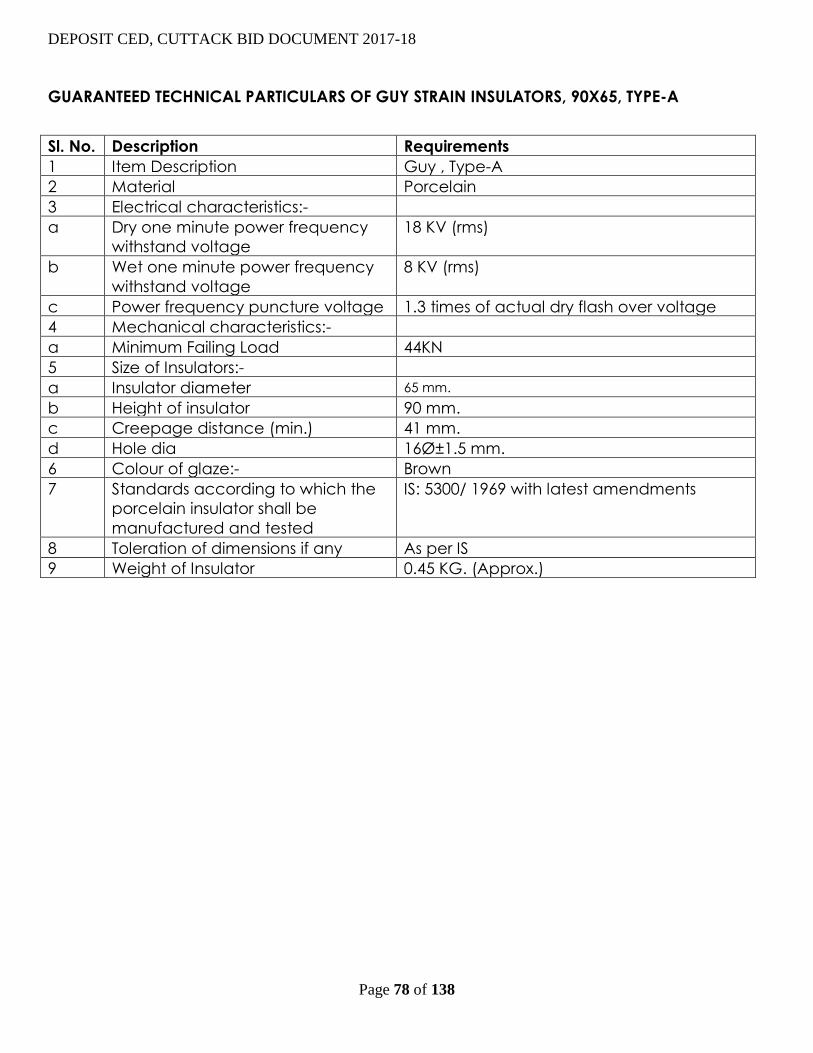
DEPOSIT CED, CUTTACK BID DOCUMENT 2017-18
Page 78 of 138
GUARANTEED TECHNICAL PARTICULARS OF GUY STRAIN INSULATORS, 90X65, TYPE-A
Sl. No. Description Requirements
1 Item Description Guy , Type-A
2 Material Porcelain
3 Electrical characteristics:-
a Dry one minute power frequency
withstand voltage
18 KV (rms)
b Wet one minute power frequency
withstand voltage
8 KV (rms)
c Power frequency puncture voltage 1.3 times of actual dry flash over voltage
4 Mechanical characteristics:-
a Minimum Failing Load 44KN
5 Size of Insulators:-
a Insulator diameter 65 mm.
b Height of insulator 90 mm.
c Creepage distance (min.) 41 mm.
d Hole dia 16ر1.5 mm.
6 Colour of glaze:- Brown
7 Standards according to which the
porcelain insulator shall be
manufactured and tested
IS: 5300/ 1969 with latest amendments
8 Toleration of dimensions if any As per IS
9 Weight of Insulator 0.45 KG. (Approx.)

DEPOSIT CED, CUTTACK BID DOCUMENT 2017-18
Page 79 of 138
GUARANTEED TECHNICAL PARTICULARS OF 11KV V CROSS ARM
Sl. No. Description Requirements
1 Type of Cross arm “V” Type
2 Grade of steel 43A Mild steel
3 Steel standard As per IS: 2062/ 1992
4 Fabrication standard As per IS: 802/ 1978
5 Dimension As per Drawing No.-REC/ A13
6 Steel section to be used ISMC: 75mm.x40mm.x6mm.
Flat: 50mm.x6mm.
7 Weight of MS Channel per meter 6.8 KG.
8 Minimum strength of MS channel As per IS: 808 (Revised)
9 Minimum weight of cross arm 10.2KG.
10 Standard of galvanization Hot dip galvanization as per IS:2629/92
11 Minimum average Mass of Zinc
Coating
610gm./ Mtr²
12 Uniformity of zinc coating As per IS:2633/ 1986

DEPOSIT CED, CUTTACK BID DOCUMENT 2017-18
Page 80 of 138
GUARANTEED TECHNICAL PARTICULARS OF 11KV PIN INSULATORS
Sl. No. Description Requirement
1 Item Description 11 KV Pin type insulator
2a Material Porcelain
2b Type of insulator Type B
3 Electrical characteristics:-
a Highest system voltage 12KV (rms)
b Nominal system voltage 11KV (rms)
c Visible discharge voltage 9KV (rms)
d Dry power frequency withstand
voltage
70KV (rms)
e Wet power frequency withstand
voltage
40KV (rms)
f Dry power frequency flashover
voltage
75KV (rms)
g Wet power frequency flashover
voltage
45KV (rms)
h Impulse withstand voltage (1.2/50
micro second wave) +ve
100KVP
i Impulse withstand voltage (1.2/50
micro second wave) -ve
110KVP
j Impulse flashover voltage (1.2/50
micro second wave) +ve
110KVP
k Impulse flashover voltage (1.2/50
micro second wave) -ve
120KVP
l Power frequency puncture voltage 110 KV (rms)
4 Mechanical characteristics:-
a Electro Mechanical Failing Load 10 KN
5 Size of Insulators:-
a Insulator diameter 165 mm.
b Height of insulator 145 mm.
c Creepage distance (min.) 320 mm.
6 Colour of glaze:- Brown
7 Standards according to which the
porcelain insulator shall be
manufactured and tested
IS: 731/ 1971 with latest amendments
8 Toleration of dimensions if any As per IS
9 Weight of Insulator 2.2 KG. (Approx.)

DEPOSIT CED, CUTTACK BID DOCUMENT 2017-18
Page 81 of 138
TYPICAL DRAWINGS 1 Typical Drawing of Dead-End (Anchoring Assembly)
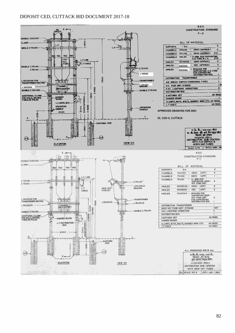
DEPOSIT CED, CUTTACK BID DOCUMENT 2017-18
82
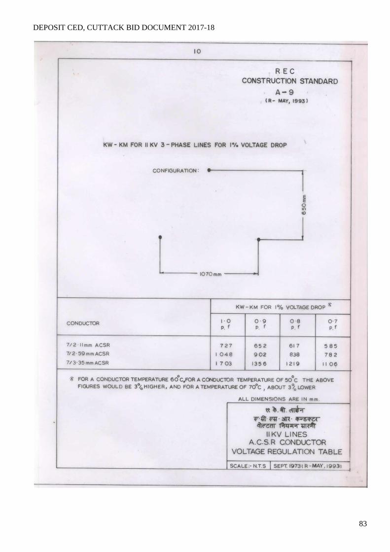
DEPOSIT CED, CUTTACK BID DOCUMENT 2017-18
83

DEPOSIT CED, CUTTACK BID DOCUMENT 2017-18
84

DEPOSIT CED, CUTTACK BID DOCUMENT 2017-18
85

DEPOSIT CED, CUTTACK BID DOCUMENT 2017-18
86
LLT
DRAWING OF LT DISTRIBUTION BOX
N.B.- Separate terminal bar to be provided for neutral connection

DEPOSIT CED, CUTTACK BID DOCUMENT 2017-18
87
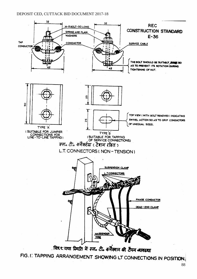
DEPOSIT CED, CUTTACK BID DOCUMENT 2017-18
88

DEPOSIT CED, CUTTACK BID DOCUMENT 2017-18
89

DEPOSIT CED, CUTTACK BID DOCUMENT 2017-18
90
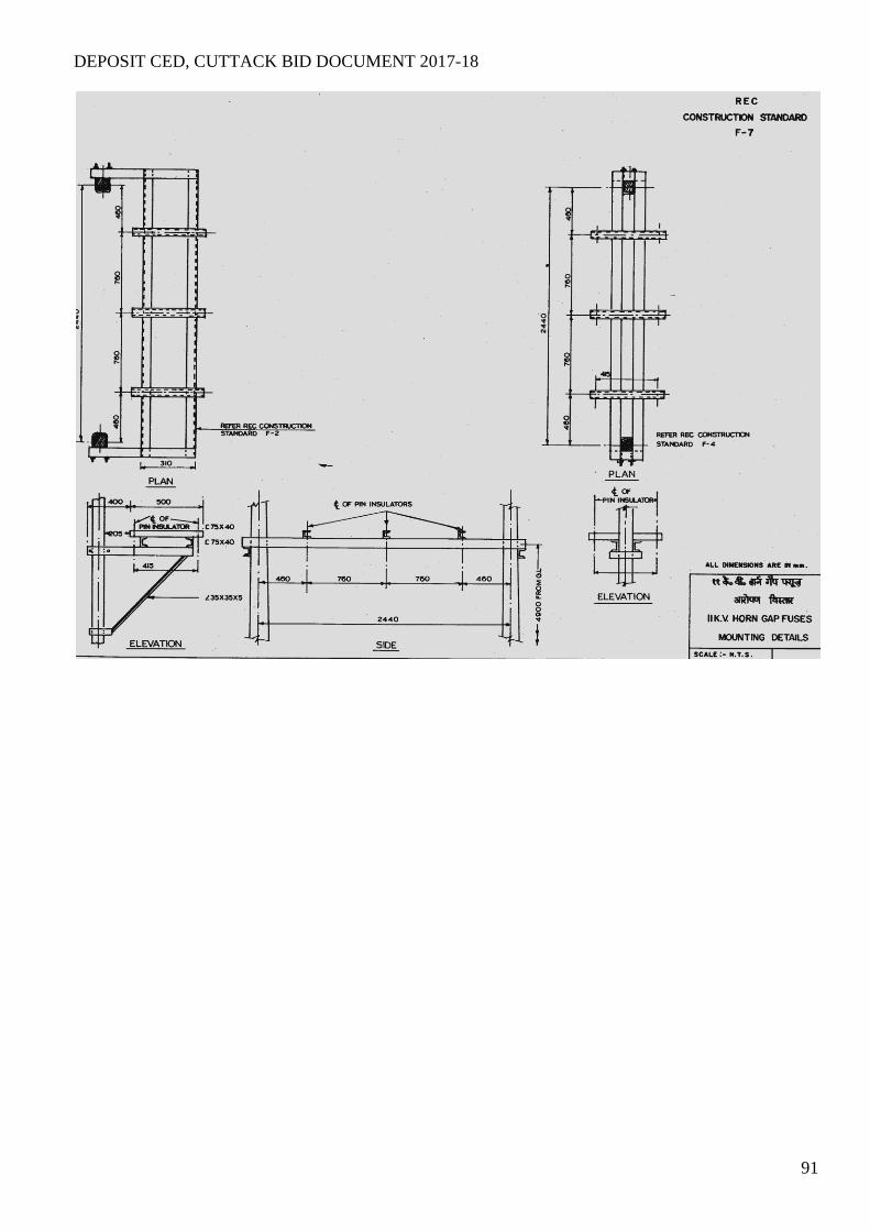
DEPOSIT CED, CUTTACK BID DOCUMENT 2017-18
91

DEPOSIT CED, CUTTACK BID DOCUMENT 2017-18
92

DEPOSIT CED, CUTTACK BID DOCUMENT 2017-18
93
SECTION – VI ANNEXURE
BID PROPOSAL SHEETS

94
SCHEDULE OF QUANTITY
Sl. No. Package
No.
Place Quantity
1 1 Bayree Railway Station a. Up gradation of transformer capacity from 63
KVA,11/0.4 KV to 100 KVA,11/0.4 KV,along with
shifting and relocation of DP structure.
b. Const. of LT line 3P4W with ABC=0.13 K.M
c. Dismantling and Shifting of 63 KVA S/S-1 No.
2 2 Kapilash Road Railway Station a. Shifting and relocation of 100 KVA,11/0.4 KV S/S
b. Construction of a four pole structure=1 No
c. Construction of 11 KV line 3P3W=0.01 K.M
3 3 Charbatia Railway Station a.Shifting and relocation of 100 KVA,11/0.4 KV S/S
b. Construction of 11 KV line 3P3W=0.05 K.M

DEPOSIT CED, CUTTACK BID DOCUMENT 2017-18
95
PRICE SCHEDULE FORMAT
SCHEDULE OF QUANTITY & PRICE for Bayree railway station.
(Firms shall quote the unit rate and total rates including all taxes and Duties)
Refer Annexure Bidders Name & Address :-
To A.G.M(Elect.)
C.E.D Cuttack
Dear Sir, We hereby furnish the detailed price of supply, erection & testing of the equipment & materials covered under the entire scope of shifting
and relocation of lines/S/S along with construction of 11 KV line/L.T line etc. in Bayree railway station under Jajpur District of Orissa under 100 % deposit scheme on partly turnkey basis.
SCHEDULE FOR PRICE BID (1) Sl No
Description of work Unit Qnty. Unit Rate
Total Price

DEPOSIT CED, CUTTACK BID DOCUMENT 2017-18
96
1 Up gradation of Distribution Transformer capacity from 63 KVA,11/0.4 KV to 100 KVA,11/0.4 KVA, 11/0.4 KV, comprising of
I) A. Erection of 100 KVA, 11/0.4KV, 3-Phase Distribution Transformer with all accessories such as LTDB,Earthing,L.A,L.T PVC Cable, etc as per specification
II) B. Shifting and relocation of 63 KVA,11/0.4 KV DP Structure-1 No with 9 mtr. 300 kg PSC Pole for DP structure along with Pressure Channels, AB Switch & HG Fuse mounting Channels , transformer mounting Channel etc. and angle for supporting 11 KV 3-pole AB Switch, HG Fuse unit, anti climbing device with fasteners, belting and belting support for transformer, danger plate, nuts bolts & washers, preformed insulator binding, and required hardware, 5 nos. of earthing arrangement with electrodes, cable for connection of transformer to LTDB,GI pipe & clamps for routing of cable, construction of barbed wire fencing as per specification & all other sundry items complete as per specification.
II) Construction of 3 Phase 4Wire ABC LT OH Lines (Span = 40m), complete work as per specification comprising of
A.Supply & stringing of XLPE Insulated 3-phase 4W ABC (3X50+1x35) sq. mm as per specification.
B.Supply & erection of 8 mtr 200KG PSC Pole along with pole concreting,
earthing arrangement, eye hook, suspension/dead end clamp including belting of clamps, etc. complete as required for supporting LT XLPE insulated AB conductor, anti climbing device with fastners, danger plate, nuts, bolts & washers and required hardware, LT Stay set complete as per specification. III)Dismantling and shifting of 63 KVA,11/0.4 KV S/S= 1 No .
No K.M No
01
0.13 1
N.B: You have to submit the detail statement regarding unit price as per the Annexure-1.
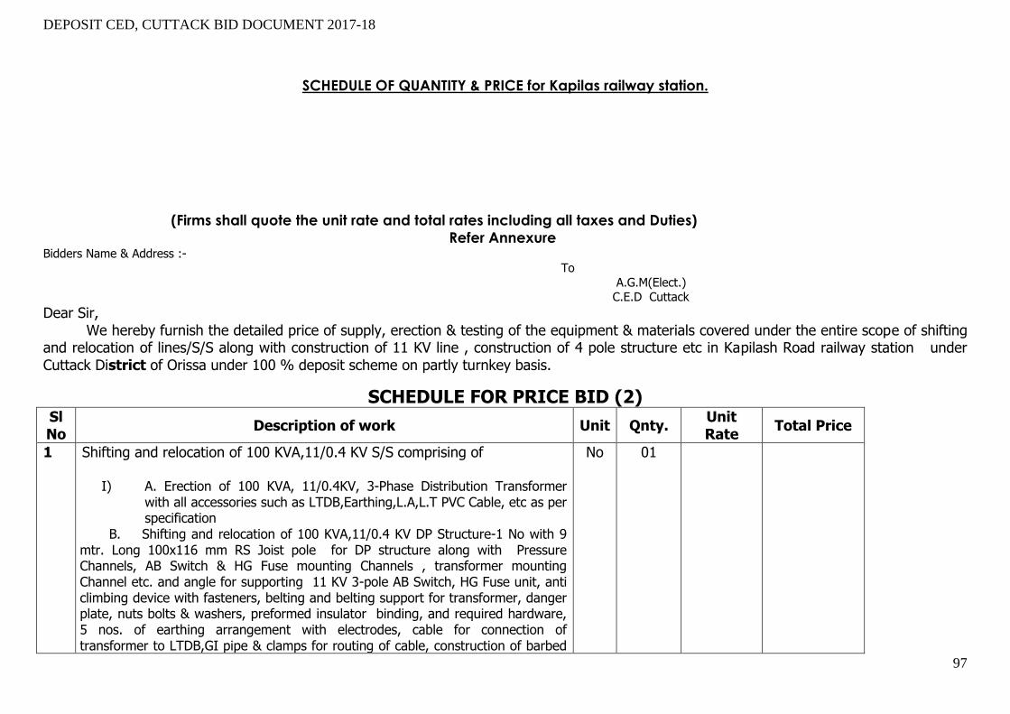
DEPOSIT CED, CUTTACK BID DOCUMENT 2017-18
97
SCHEDULE OF QUANTITY & PRICE for Kapilas railway station.
(Firms shall quote the unit rate and total rates including all taxes and Duties)
Refer Annexure Bidders Name & Address :- To
A.G.M(Elect.) C.E.D Cuttack
Dear Sir, We hereby furnish the detailed price of supply, erection & testing of the equipment & materials covered under the entire scope of shifting
and relocation of lines/S/S along with construction of 11 KV line , construction of 4 pole structure etc in Kapilash Road railway station under Cuttack District of Orissa under 100 % deposit scheme on partly turnkey basis.
SCHEDULE FOR PRICE BID (2) Sl No
Description of work Unit Qnty. Unit Rate
Total Price
1
Shifting and relocation of 100 KVA,11/0.4 KV S/S comprising of
I) A. Erection of 100 KVA, 11/0.4KV, 3-Phase Distribution Transformer with all accessories such as LTDB,Earthing,L.A,L.T PVC Cable, etc as per specification
II) B. Shifting and relocation of 100 KVA,11/0.4 KV DP Structure-1 No with 9 mtr. Long 100x116 mm RS Joist pole for DP structure along with Pressure Channels, AB Switch & HG Fuse mounting Channels , transformer mounting Channel etc. and angle for supporting 11 KV 3-pole AB Switch, HG Fuse unit, anti climbing device with fasteners, belting and belting support for transformer, danger plate, nuts bolts & washers, preformed insulator binding, and required hardware, 5 nos. of earthing arrangement with electrodes, cable for connection of transformer to LTDB,GI pipe & clamps for routing of cable, construction of barbed
No
01
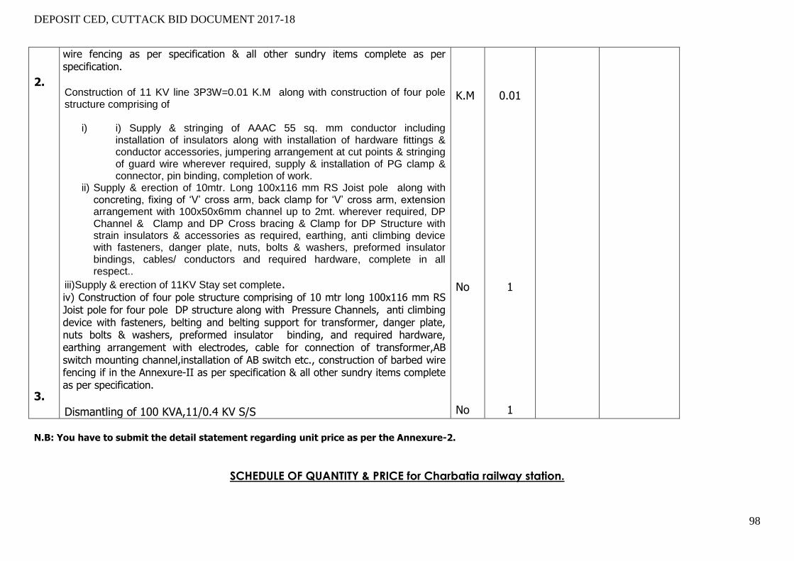
DEPOSIT CED, CUTTACK BID DOCUMENT 2017-18
98
2. 3.
wire fencing as per specification & all other sundry items complete as per specification.
Construction of 11 KV line 3P3W=0.01 K.M along with construction of four pole structure comprising of
i) i) Supply & stringing of AAAC 55 sq. mm conductor including installation of insulators along with installation of hardware fittings & conductor accessories, jumpering arrangement at cut points & stringing of guard wire wherever required, supply & installation of PG clamp & connector, pin binding, completion of work.
ii) Supply & erection of 10mtr. Long 100x116 mm RS Joist pole along with concreting, fixing of ‘V’ cross arm, back clamp for ‘V’ cross arm, extension arrangement with 100x50x6mm channel up to 2mt. wherever required, DP Channel & Clamp and DP Cross bracing & Clamp for DP Structure with strain insulators & accessories as required, earthing, anti climbing device with fasteners, danger plate, nuts, bolts & washers, preformed insulator bindings, cables/ conductors and required hardware, complete in all respect..
iii)Supply & erection of 11KV Stay set complete. III) iv) Construction of four pole structure comprising of 10 mtr long 100x116 mm RS
Joist pole for four pole DP structure along with Pressure Channels, anti climbing device with fasteners, belting and belting support for transformer, danger plate, nuts bolts & washers, preformed insulator binding, and required hardware, earthing arrangement with electrodes, cable for connection of transformer,AB switch mounting channel,installation of AB switch etc., construction of barbed wire fencing if in the Annexure-II as per specification & all other sundry items complete as per specification.
Dismantling of 100 KVA,11/0.4 KV S/S
K.M No No
0.01 1 1
N.B: You have to submit the detail statement regarding unit price as per the Annexure-2.
SCHEDULE OF QUANTITY & PRICE for Charbatia railway station.
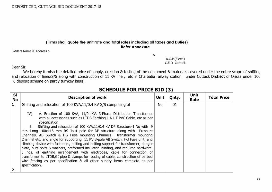
DEPOSIT CED, CUTTACK BID DOCUMENT 2017-18
99
(Firms shall quote the unit rate and total rates including all taxes and Duties)
Refer Annexure Bidders Name & Address :-
To A.G.M(Elect.)
C.E.D Cuttack
Dear Sir, We hereby furnish the detailed price of supply, erection & testing of the equipment & materials covered under the entire scope of shifting
and relocation of lines/S/S along with construction of 11 KV line , etc in Charbatia railway station under Cuttack District of Orissa under 100 % deposit scheme on partly turnkey basis.
SCHEDULE FOR PRICE BID (3) Sl No
Description of work Unit Qnty. Unit Rate
Total Price
1 2.
Shifting and relocation of 100 KVA,11/0.4 KV S/S comprising of
IV) A. Erection of 100 KVA, 11/0.4KV, 3-Phase Distribution Transformer with all accessories such as LTDB,Earthing,L.A,L.T PVC Cable, etc as per specification
V) B. Shifting and relocation of 100 KVA,11/0.4 KV DP Structure-1 No with 9 mtr. Long 100x116 mm RS Joist pole for DP structure along with Pressure Channels, AB Switch & HG Fuse mounting Channels , transformer mounting Channel etc. and angle for supporting 11 KV 3-pole AB Switch, HG Fuse unit, anti climbing device with fasteners, belting and belting support for transformer, danger plate, nuts bolts & washers, preformed insulator binding, and required hardware, 5 nos. of earthing arrangement with electrodes, cable for connection of transformer to LTDB,GI pipe & clamps for routing of cable, construction of barbed wire fencing as per specification & all other sundry items complete as per specification.
No
01

DEPOSIT CED, CUTTACK BID DOCUMENT 2017-18
100
Construction of 11 KV line 3P3W=0.05 K.M comprising of
i) Supply & stringing of AAAC 55 sq. mm conductor including installation of insulators along with installation of hardware fittings & conductor accessories, jumpering arrangement at cut points & stringing of guard wire wherever required, supply & installation of PG clamp & connector, pin binding, completion of work. ii)Supply & erection of 9mtr. Long 100x116 mm RS Joist pole along with concreting, fixing of ‘V’ cross arm, back clamp for ‘V’ cross arm, extension arrangement with 100x50x6mm channel up to 2mt. wherever required, DP Channel & Clamp and DP Cross bracing & Clamp for DP Structure with strain insulators & accessories as required, earthing, anti climbing device with fasteners, danger plate, nuts, bolts & washers, preformed insulator bindings, cables/ conductors and required hardware, complete in all respect..
iii)Supply & erection of 11KV Stay set complete. VI) iv) Dismantling of 100 KVA,11/0.4 KV S/S
K.M No No
0.01 2 1
N.B: You have to submit the detail statement regarding unit price as per the Annexure-3.

DEPOSIT CED, CUTTACK BID DOCUMENT 2017-18
101
Annexure-1
PRICE BID FOR INDIVIDUAL ITEM WITH ERECTION COST INCLUDING TAXES AND DUTIES AND COMMISSIONING (FOR BAYREE RAILWAY STATION)
Sl. No. Description of Materials
Unit Total
quantity OSM CSM
Unit Price including all taxes and
duties,erection and
commissioning
Total Amount=(Total quantityx Unit
price)
Part-A Shifting &relocation of 63 KVA S/S along with up gradation of s/s capacity from 63 KVA, to 100 KVA,11/0.4 KV
1 9 mtr long 300 Kg. PSC Pole No. 2 2.00
2
Pressure Channel 100 x 50 x 6mm MS channel each 2.8 mtr. Long( 9.2 K.g. per mtr.)x2 Nos K.g. 51.52
51.52
3
Transformer mounting chhanel 100 x 50 x 6mm MS channel each 2.8 mtr. Long( 9.2 K.g. per mtr.)x2 Nos K.g. 51.52
51.52
4
AB Swith & HG Fuse, Mounting Channel 75x40x6 -2.8 mtr.long, 4 nos.(6.8K.g. per
mtr.) K.g. 76.16 76.16
5
Cantilever chhanel for supporting AB Switch arm, 75x40x6-1 mtr. Long, 2
nos.(6.8 K.g. per mtr.) K.g. 13.6 13.60
6
Cantilever chhanel for supporting HG Fuse 50 x 50 x 6 mm MS Angel (1.0 mtrs. Long 2 nos.)4.5K.g. per mtr. K.g. 9
9.00
7
Angel for Cantilever arrrangement for AB Switch & HG Fuse 50 x 50 x 6 -2 mtr .each 2 nos.(4.5 K.g. per mtr.) K.g. 18
18.00
8
Transformer belting Angel 50 x 50 x 6 mm - 2.8 mtr. Long 2 nos.(4.5 K.g. per mtr.) with side angel ( Total 7 mtr.) K.g. 31.5
31.50

DEPOSIT CED, CUTTACK BID DOCUMENT 2017-18
102
9
Angel for mounting LT distribution Box 50 x 50 x 6 mm MS Angel -2.5 mtrs.each Long 2 nos.( 4.5 K.g. per mtr.) K.g. 22.5
22.50
10 11KV AB Switch 3 Pole (200 Amp) Set 1 1.00
11 11KV HG Fuse 3 Pole (400 Amp) No. 1 1.00
12 11 KV L.A. 12KV-10KA No. 3
3.00
13 H.T.stay set ( Complete ) Set 2 2.00
14 H.T. Stay Insulator No. 2 2.00
15 H.T. Stay clamp (1.95 K.g./ Pair ) Pair 2 2.00
16 7/10 SWG Stay Wire K.g. 20 20.00
17 GI Pipe Earthing 40 Dia Medium gage 3 mtrs. Long No. 5
5.00
18 No.6 GI Wire K.g. 20
20.00
19 40x6mm GI Flat for nutral K.g. 20 20.00
20
Fixing and concreating of stay set with 0.5Cum cement concret foundation 1:3:6 size
( 900mmx600mmx900mm) using 40mm BHG metal with all labour and material except stay set , stay wire , stay insulator . No. 2
2.00
21
Concreting of support C.C - 1:4:8 using 40mm BHG metal size - 5'x2'x2' = 20CFT = 0.570Cum Padding 900x600x150mm = 0.081 0.651Cum @ 3071.25= 1999.38each NO 2
2.00

DEPOSIT CED, CUTTACK BID DOCUMENT 2017-18
103
22
Couping of support section 15''x15'' ( 3.9Cft) height 2'-6' ( 1' - 6'' above G.L & 1' - 0' below G.L ) in C.C 1:2:4 using 12mm BHG metal & curing for 5 days Nos 2
2.00
23
Materials for Massionary work for Earth Pit,Charcoal, Salt etc including construction of earthing chamber (Size: 2"x2") and RCC slab cover No. 5
5.00
24 55mm2 AAAC Km 0.04
0.04
25 Red Oxide paint Ltr 3 3.00
26 All. Paint Ltr 4 4.00
27 Ms Nut , Bolt & Washer K.g. 36
36.00
28 100KVA, 11/0.4KV 3 star rated TFR AL No 1
1.00
29
L.T. Distribution box including Kit Kat fuse with MCCB for 63KVA S/S ( As pre CESU specification) No. 1
1.00
30 3 1/2 x 150mm2 PVC Cable for 100 KVA TFR. Mtr. 25
25.00
31
Barbed Fencing (size 15'x10' )with constn. of retaining wall ,erection of RCC fencing post, Sand filling and metal spreading, Fixing of Iron gril gate etc as per CESU
specification No 1 1.00
Part-B
L T Line = 0.13 K.M
-
1 8 Mtr. long 200 Kg. PSC Pole No. 3
3.00
2 Concrete slab for base plate size 2ftx2ftx2" thickness for each PSC pole No. 3
3.00
3 LT Stay set Complete Set 1
4 7/12 SWG Stay Wire K.g. 10

DEPOSIT CED, CUTTACK BID DOCUMENT 2017-18
104
10.00
5 LT Stay clamp (1.4 K.g./ Pair ) pair 1
1.00
6 LT Stay Insulator No. 1
1.00
7
Fixing and concereating of stay set with 0.5Cum cement concret foundation 1:3:6 size (900mmx600mmx900mm) using 40mm BHG metal with all labour and material except stay set, stay wire, stay insulator.
No. 1
1.00
8 Dead end clamp No. 2
2.00
9 Suspension clamp with I-Hook No. 2
2.00
10 Strain fittings No. 1
1.00
11 Guy grip Dead end No. 1
1.00
12 Nuts and Bolts Kg 2
13 Earthing Coil each 5th pole to earth No. 1
1.00
14 AB Cable( 3 x50 + 1x35mm² ) K.m. 0.13
0.13
Part-C
Dismantling of s/s
1 Labour cost for dismantling of S/S
No 1
1.00
NB: The bidders are directed to quote the Unit Price including all taxes and duties along with both erection and commissioning of indivisual materials in the above FORMAT. Also for OSM materials the bidders must quote the both erection and commission
charges excluding of material cost. After quoting unit price, the total cost of materials including CSM+ erection & commissioning of CSM+ erection & commissioning of OSM materials should be derived by the bidders which will be treated as total cost of the
work quoted by the bidder.

DEPOSIT CED, CUTTACK BID DOCUMENT 2017-18
105
Date : Signature of the Bidder with
Place : Name & Seal

DEPOSIT CED, CUTTACK BID DOCUMENT 2017-18
106
Annexure-2
PRICE BID FOR INDIVIDUAL ITEM WITH ERECTION COST INCLUDING TAXES AND DUTIES AND COMMISSIONING (FOR KAPILASH ROAD RAILWAY STATION)
Sl. No. Description of Materials
Unit Total
quantity OSM CSM
Unit Price including all taxes and duties,erection and commissioning
Amount
Shifting and relocation of 11 KV line along with construction of a four pole structure
1 100x116mm RS Joist 10mtr long 4 Nos x23kg= 920Kg Kg 920 920.00
2
Pressure Channel 100 x 50 x 6mm MS channel each 2.8 mtr. Long( 9.2
K.g. per mtr.)x8 Nos K.g. 206.08 206.08
3
AB Swith & HG Fuse, Mounting
Channel 75x40x6 -2.8 mtr.long, 4 nos.(6.8K.g. per mtr.) K.g. 76.16 76.16
4 11KV AB Switch 3 Pole (400 Amp) Set 2 2.00
5 11 KV G I Pin No 12 12.00
6 11 KV Pin Insulator No 12
7 11 KV HW Fittings (B&S) No 15 15.00
8 11 KV Disc Insulator (B&S) No 45 45.00
9 H.T.stay set ( Complete ) Set 1 1.00
10 H.T. Stay Insulator No 1 1.00
11 H.T. Stay clamp (1.95 K.g./ Pair ) Pair 1 1.00
12 7/10 SWG Stay Wire K.g. 12 12.00

DEPOSIT CED, CUTTACK BID DOCUMENT 2017-18
107
13
Fixing and concereating of stay set with 0.5Cum cement concret foundation 1:3:6 size (900mmx600mmx900mm) using 40mm BHG metal with all labour and material except stay set, stay wire, stay insulator. No 1 1.00
14 Earthing of Supports (Coil Earth) No 2 2.00
15 80mm2 AAAC Km 0.3 0.30
16
Concreting of support C.C - 1:4:8
using 40mm BHG metal size - 5'x2'x2' = 20CFT = 0.570Cum
Padding 900x600x150mm = 0.081
0.651Cum
x3071.25= 1999.38 each cut point No 4 4.00
17
Couping of support section 15''x15'' ( 3.9Cft) height 2'-6' ( 1' - 6'' above G.L & 1' - 0' below G.L ) in C.C 1:2:4 using 12mm BHG metal & curing for 5 days No 4 4.00
18 Red Oxide paint Ltr 10 10.00
19 All. Paint Ltr 10 10.00
20 GI barbed wire anticlimbing device 2 Kg. Per support Kg 10 10.00
21 100 x 50 x 6mm MS channel for Cut point Kg 34.36 34.36
22 Ms Nut , Bolt & Washer K.g. 35 35.00
Part-B Shifting &relocation of 100 KVA S/S .
1 100x116x6mm RS joist 9mtr x1nos x23Kg = 414kg Kg 414 414.00
2
Pressure Channel 100 x 50 x 6mm MS channel each 2.8 mtr. Long( 9.2 K.g. per mtr.)X2 Nos K.g. 51.52 51.52
3
S/S D P Bressing chhanel 75 x 40 x 6mm MS channel each 2.8 mtr. Long( 6.8 K.g. per mtr.)X2 Nos K.g. 40 40.00
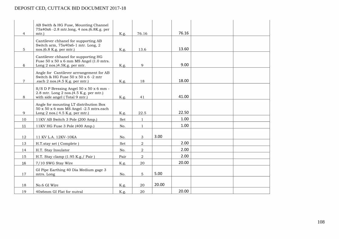
DEPOSIT CED, CUTTACK BID DOCUMENT 2017-18
108
4
AB Swith & HG Fuse, Mounting Channel 75x40x6 -2.8 mtr.long, 4 nos.(6.8K.g. per mtr.) K.g. 76.16 76.16
5
Cantilever chhanel for supporting AB Switch arm, 75x40x6-1 mtr. Long, 2 nos.(6.8 K.g. per mtr.) K.g. 13.6 13.60
6
Cantilever chhanel for supporting HG Fuse 50 x 50 x 6 mm MS Angel (1.0 mtrs. Long 2 nos.)4.5K.g. per mtr. K.g. 9 9.00
7
Angle for Cantilever arrrangement for AB Switch & HG Fuse 50 x 50 x 6 -2 mtr .each 2 nos.(4.5 K.g. per mtr.) K.g. 18 18.00
8
S/S D P Bressing Angel 50 x 50 x 6 mm - 2.8 mtr. Long 2 nos.(4.5 K.g. per mtr.) with side angel ( Total 9 mtr.) K.g. 41 41.00
9
Angle for mounting LT distribution Box 50 x 50 x 6 mm MS Angel -2.5 mtrs.each Long 2 nos.( 4.5 K.g. per mtr.) K.g. 22.5 22.50
10 11KV AB Switch 3 Pole (200 Amp.) Set 1 1.00
11 11KV HG Fuse 3 Pole (400 Amp.) No. 1 1.00
12 11 KV L.A. 12KV-10KA No. 3
3.00
13 H.T.stay set ( Complete ) Set 2 2.00
14 H.T. Stay Insulator No. 2 2.00
15 H.T. Stay clamp (1.95 K.g./ Pair ) Pair 2 2.00
16 7/10 SWG Stay Wire K.g. 20 20.00
17 GI Pipe Earthing 40 Dia Medium gage 3 mtrs. Long No. 5
5.00
18 No.6 GI Wire K.g. 20
20.00
19 40x6mm GI Flat for nutral K.g. 20 20.00

DEPOSIT CED, CUTTACK BID DOCUMENT 2017-18
109
20
Fixing of stay set with 0.5Cum cement concret foundation 1:3:6 size ( 900mmx600mmx900mm) using 40mm BHG metal with all labour and material except stay set , stay wire , stay insulator . No. 2 2.00
21
Concreting of support C.C - 1:4:8 using 40mm BHG metal size - 5'x2'x2' = 20CFT = 0.570Cum Padding 900x600x150mm = 0.081 0.651Cum @ 3071.25= 1999.38each NO 2 2.00
22
Couping of support section 15''x15'' ( 3.9Cft) height 2'-6' ( 1' - 6'' above G.L & 1' - 0' below G.L ) in C.C 1:2:4 using 12mm BHG metal & curing for 5 days Nos 2 2.00
23
Materials for Machinery work for Earth Pit,Charcoal, Salt etc including construction of earthing chamber (Size: 2'x2') and RCC slab cover No. 5 5.00
24 55mm2 AAAC Km 0.04 0.04
25 Red Oxide paint Ltr 3 3.00
26 All. Paint Ltr 4 4.00
27 Black Paint Ltr 0.5
0.50
28 Ms Nut , Bolt & Washer K.g. 36
36.00
29 100KVA, 11/0.4KV 3 star rated TFR AL No 1
1.00 0.00
30
L.T. Distribution box including Kit Kat fuse with MCCB for 100KVA S/S ( As pre CESU specification) No. 1
1.00
31
3 1/2 x 150mm2 PVC Cable for 100 KVA TFR. Mtr. 12
12.00
32 Plinth for transformer 6' hight (Below G L 2') x5'x5' No 1 1.00
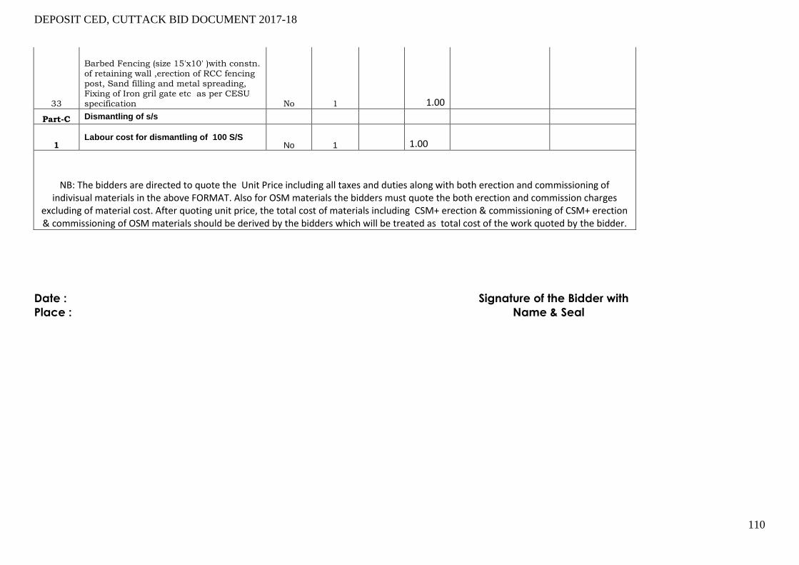
DEPOSIT CED, CUTTACK BID DOCUMENT 2017-18
110
33
Barbed Fencing (size 15'x10' )with constn. of retaining wall ,erection of RCC fencing post, Sand filling and metal spreading, Fixing of Iron gril gate etc as per CESU specification No 1 1.00
Part-C Dismantling of s/s
1 Labour cost for dismantling of 100 S/S
No 1
1.00
NB: The bidders are directed to quote the Unit Price including all taxes and duties along with both erection and commissioning of indivisual materials in the above FORMAT. Also for OSM materials the bidders must quote the both erection and commission charges
excluding of material cost. After quoting unit price, the total cost of materials including CSM+ erection & commissioning of CSM+ erection & commissioning of OSM materials should be derived by the bidders which will be treated as total cost of the work quoted by the bidder.
Date : Signature of the Bidder with
Place : Name & Seal
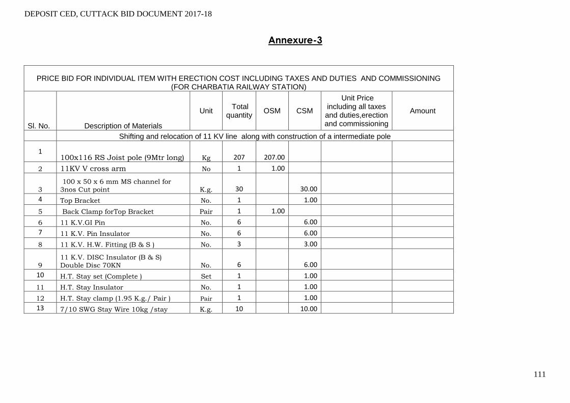
DEPOSIT CED, CUTTACK BID DOCUMENT 2017-18
111
Annexure-3
PRICE BID FOR INDIVIDUAL ITEM WITH ERECTION COST INCLUDING TAXES AND DUTIES AND COMMISSIONING (FOR CHARBATIA RAILWAY STATION)
Sl. No. Description of Materials
Unit Total
quantity OSM CSM
Unit Price including all taxes and duties,erection and commissioning
Amount
Shifting and relocation of 11 KV line along with construction of a intermediate pole
1 100x116 RS Joist pole (9Mtr long) Kg 207 207.00
2 11KV V cross arm No 1 1.00
3
100 x 50 x 6 mm MS channel for
3nos Cut point K.g. 30 30.00
4 Top Bracket No. 1 1.00
5 Back Clamp forTop Bracket Pair 1 1.00
6 11 K.V.GI Pin No. 6 6.00
7 11 K.V. Pin Insulator No. 6 6.00
8 11 K.V. H.W. Fitting (B & S ) No. 3 3.00
9
11 K.V. DISC Insulator (B & S)
Double Disc 70KN No. 6 6.00
10 H.T. Stay set (Complete ) Set 1 1.00
11 H.T. Stay Insulator No. 1 1.00
12 H.T. Stay clamp (1.95 K.g./ Pair ) Pair 1 1.00
13 7/10 SWG Stay Wire 10kg /stay K.g. 10 10.00
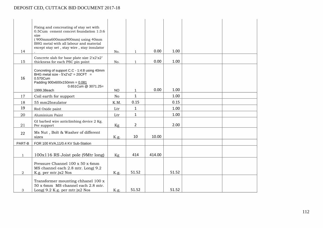
DEPOSIT CED, CUTTACK BID DOCUMENT 2017-18
112
14
Fixing and concreating of stay set with 0.5Cum cement concret foundation 1:3:6 size ( 900mmx600mmx900mm) using 40mm BHG metal with all labour and material except stay set , stay wire , stay insulator . No. 1 0.00 1.00
15 Concrete slab for base plate size 2'x2'x2" thickness for each PSC pin point No. 1 0.00 1.00
16
Concreting of support C.C - 1:4:8 using 40mm BHG metal size - 5'x2'x2' = 20CFT = 0.570Cum Padding 900x600x150mm = 0.081 0.651Cum @ 3071.25= 1999.38each NO 1 0.00 1.00
17 Coil earth for support No 1 1.00
18 55 mm2Insulator K.M. 0.15 0.15
19 Red Oxide paint Ltr 1 1.00
20 Aluminium Paint Ltr 1 1.00
21 GI barbed wire anticlimbing device 2 Kg. Per support Kg 2 2.00
22 Ms Nut , Bolt & Washer of different
sizes K.g. 10 10.00
PART-B FOR 100 KVA,11/0.4 KV Sub-Station
1 100x116 RS Joist pole (9Mtr long) Kg 414 414.00
2
Pressure Channel 100 x 50 x 6mm
MS channel each 2.8 mtr. Long( 9.2
K.g. per mtr.)x2 Nos K.g. 51.52 51.52
3
Transformer mounting chhanel 100 x
50 x 6mm MS channel each 2.8 mtr.
Long( 9.2 K.g. per mtr.)x2 Nos K.g. 51.52 51.52

DEPOSIT CED, CUTTACK BID DOCUMENT 2017-18
113
4
AB Swith & HG Fuse, Mounting Channel 75x40x6 -2.8 mtr.long, 4
nos.(6.8K.g. per mtr.) K.g. 76.16 76.16
5
Cantilever chhanel for supporting AB
Switch arm, 75x40x6-1 mtr. Long, 2 nos.(6.8 K.g. per mtr.) K.g. 13.6 13.60
6
Cantilever chhanel for supporting
HG Fuse 50 x 50 x 6 mm MS Angel
(1.0 mtrs. Long 2 nos.)4.5K.g. per
mtr. K.g. 9 9.00
7
Angel for Cantilever arrrangement for
AB Switch & HG Fuse 50 x 50 x 6 -2
mtr .each 2 nos.(4.5 K.g. per mtr.) K.g. 18 18.00
8
Transformer belting Angel 50 x 50 x 6
mm - 2.8 mtr. Long 2 nos.(4.5 K.g.
per mtr.) with side angel ( Total 7 mtr.) K.g. 31.5 31.50
9
Angel for mounting LT distribution
Box 50 x 50 x 6 mm MS Angel -2.5
mtrs.each Long 2 nos.( 4.5 K.g. per
mtr.) K.g. 22.5 22.50
10 11KV AB Switch 3 Pole (200 Amp) Set 1 1.00
11 11KV HG Fuse 3 Pole (400 Amp) No. 1 1.00
12 11 KV L.A. 12KV-10KA No. 3 3.00
13 H.T.stay set ( Complete ) Set 2 2.00
14 H.T. Stay Insulator No. 2 2.00
15 H.T. Stay clamp (1.95 K.g./ Pair ) Pair 2 2.00
16 7/10 SWG Stay Wire K.g. 20 20.00
17
GI Pipe Earthing 40 Dia Medium gage
3 mtrs. Long No. 5 5.00
18 No.6 GI Wire K.g. 20 20.00
19 40x6mm GI Flat for nutral K.g. 20 20.00
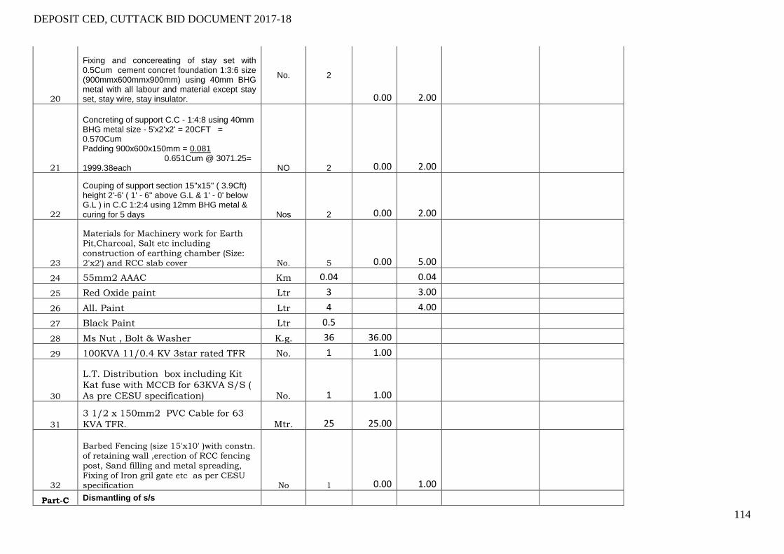
DEPOSIT CED, CUTTACK BID DOCUMENT 2017-18
114
20
Fixing and concereating of stay set with 0.5Cum cement concret foundation 1:3:6 size (900mmx600mmx900mm) using 40mm BHG metal with all labour and material except stay set, stay wire, stay insulator.
No. 2
0.00 2.00
21
Concreting of support C.C - 1:4:8 using 40mm BHG metal size - 5'x2'x2' = 20CFT = 0.570Cum Padding 900x600x150mm = 0.081 0.651Cum @ 3071.25= 1999.38each NO 2 0.00 2.00
22
Couping of support section 15''x15'' ( 3.9Cft) height 2'-6' ( 1' - 6'' above G.L & 1' - 0' below G.L ) in C.C 1:2:4 using 12mm BHG metal & curing for 5 days Nos 2 0.00 2.00
23
Materials for Machinery work for Earth Pit,Charcoal, Salt etc including construction of earthing chamber (Size: 2'x2') and RCC slab cover No. 5 0.00 5.00
24 55mm2 AAAC Km 0.04 0.04
25 Red Oxide paint Ltr 3 3.00
26 All. Paint Ltr 4 4.00
27 Black Paint Ltr 0.5
28 Ms Nut , Bolt & Washer K.g. 36 36.00
29 100KVA 11/0.4 KV 3star rated TFR No. 1 1.00
30
L.T. Distribution box including Kit
Kat fuse with MCCB for 63KVA S/S (
As pre CESU specification) No. 1 1.00
31
3 1/2 x 150mm2 PVC Cable for 63
KVA TFR. Mtr. 25 25.00
32
Barbed Fencing (size 15'x10' )with constn. of retaining wall ,erection of RCC fencing post, Sand filling and metal spreading, Fixing of Iron gril gate etc as per CESU specification No 1 0.00 1.00
Part-C Dismantling of s/s
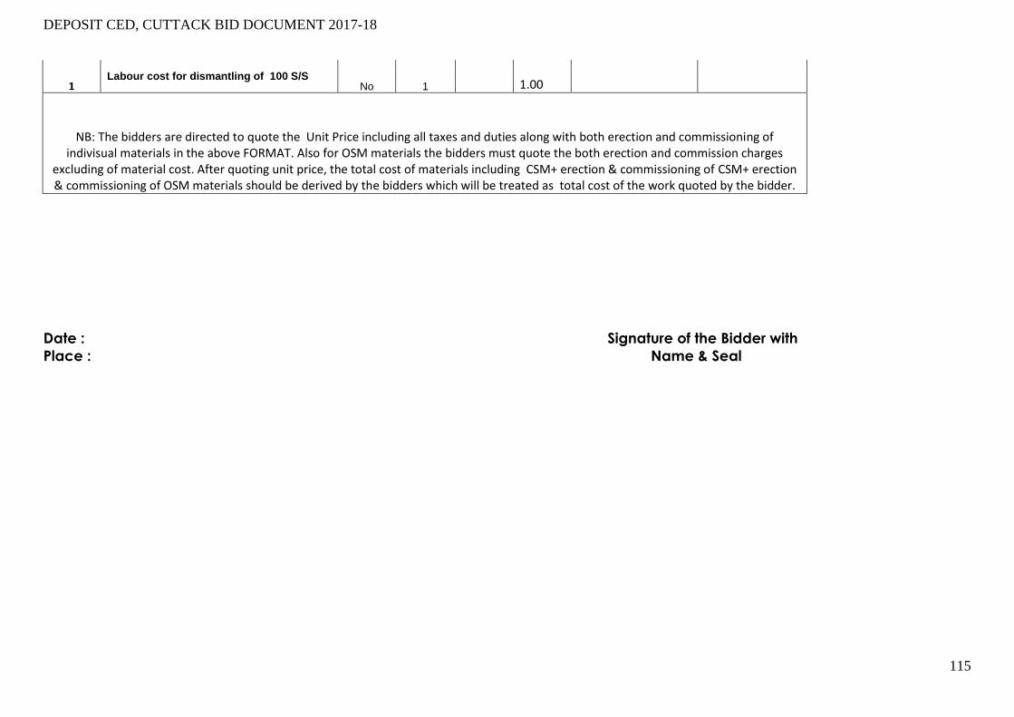
DEPOSIT CED, CUTTACK BID DOCUMENT 2017-18
115
Date : Signature of the Bidder with
Place : Name & Seal
1 Labour cost for dismantling of 100 S/S
No 1
1.00
NB: The bidders are directed to quote the Unit Price including all taxes and duties along with both erection and commissioning of indivisual materials in the above FORMAT. Also for OSM materials the bidders must quote the both erection and commission charges
excluding of material cost. After quoting unit price, the total cost of materials including CSM+ erection & commissioning of CSM+ erection & commissioning of OSM materials should be derived by the bidders which will be treated as total cost of the work quoted by the bidder.

116
Annexure-A
PROFORMA OF BANK GUARANTEE FOR EARNEST MONEY DEPOSIT Bank Guarantee No………………….
Date…………….
1. In accordance with invitation to Bid No………………….. Dated……………… of Executive
Engineer, CED,JOBRA CESU Cuttack for the purpose of …………………..
M/s………………………………. Address…………………………………………………..
……………………………………………………………………………………………………… wish / wishes to
participate in the said tender and as the Bank Guarantee for the sum of Rs…………………….
(Rupees………………………………………………….. only) valid for a period of ……………….. days (in
words) is required to be submitted by the tenderer. We the …………………………….. Bank (herein
after referred to as the bank) at the request of M/s………………………………….. hereby
unequivocally and unconditionally guarantee and undertake to pay during the above said
period or written request by the Executive Engineer, CED, CESU Cuttack , an amount not
exceeding Rs…………. (Rupees………………………………………………. only) to Collector without
any reservation. The guarantee will remain valid up to 4.00PM of date…………….. (date) and if
any further extension is required the same will be extended on receiving instruction from
M/s……………………………………………. on whose behalf this guarantee has been issued.
2. We, the …………………….. Bank do hereby undertake to pay the amounts, due and payable
under the guarantee without any demur, merely on a demand from the Executive Engineer,
CEDI, CESU Cuttack stating that the amount claimed is due by war of loss or damage caused
to or suffered by Collector by reason of any breach by the said contractor(s) of any of the terms
or conditions contained in the said agreement or by the reason of any breach by the said
contractors failure to perform the said Bid. Any such demand made on the Bank shall be
conclusive as regards the amount due and payable by the Bank under this guarantee. However,
our liability under this guarantee shall be restricted to an amount not exceeding Rs.
…………………. (in words).
3. We undertake to pay to the Collector any money so demanded not withstanding any dispute or
dispute raised by the contractor(s) / Supplier(s) in any suit or proceeding instituted / pending
before any Court or Tribunal relating thereto our liability under this agreement being absolute and
univocal. The payment made under this bond shall be a valid discharge of our liability for
payment there under and the contractor(s) / supplier(s) shall have no claim against us for making
such payment.
4. We, the …………………………. Bank our local Branch at Cuttack (detail address & Code No. of
local branch to be specified) further agree that the guarantee herein contain shall remain in full
force and effect during eh period 90 days (Ninety days) and it shall continue to do so
enforceable till all the dues of the Collector under by the virtue of the said Bid have been fully
paid and its claims satisfied or discharged or till Executive Engineer, CED, CESU Cuttack certifies that the terms and conditions of the said Bid have been fully and properly carried out by
the said contractor(s) and accordingly discharge this guarantee. Unless a demand or claim
under this guarantee is made on us in writing on or before the …………………………………………
we shall be discharged from all liabilities under this guarantee thereafter.
5. We, the ………………………………. Bank our local Branch at Cuttack further agree that Collector
shall have the fullest liberty without our consent and without affecting any manner our obligations
hereunder to very and of terms and conditions of the said Bid or to extend time of performance
by the said contractor(s) from time to time to postpone for any time or from time to time any of
the powers exercisable by Executive Engineer, CED, CESU Cuttack against the said
contractor(s) and to forebear or enforce any of terms and conditions relating to the said Bid and
we shall not be relived from our liability by reason of any such variation postponement or
extension being granted by the contractor(s) or for any forbearance act of omission on part of
Collector to the said contractor(s) or by any such matter or thing whatsoever which under the
law relating to sureties should but for this provisions have effect of so relieving us.
6. The guarantee will not discharged due to change in the name, style and constitution of the Bank
and contractor(s).
7. We, the …………………………… Bank our local Branch at Cuttack lastly undertake not to revoke
this guarantee during its currency except with the previous consent of Collector in writing.
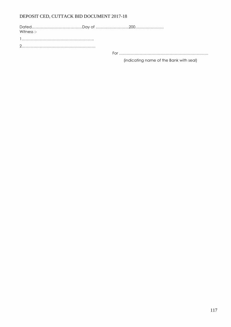
DEPOSIT CED, CUTTACK BID DOCUMENT 2017-18
117
Dated…………………………………Day of ……………………..200………………….
Witness :-
1………………………………………………..
2…………………………………………………
For ……………………………………………………………
(indicating name of the Bank with seal)
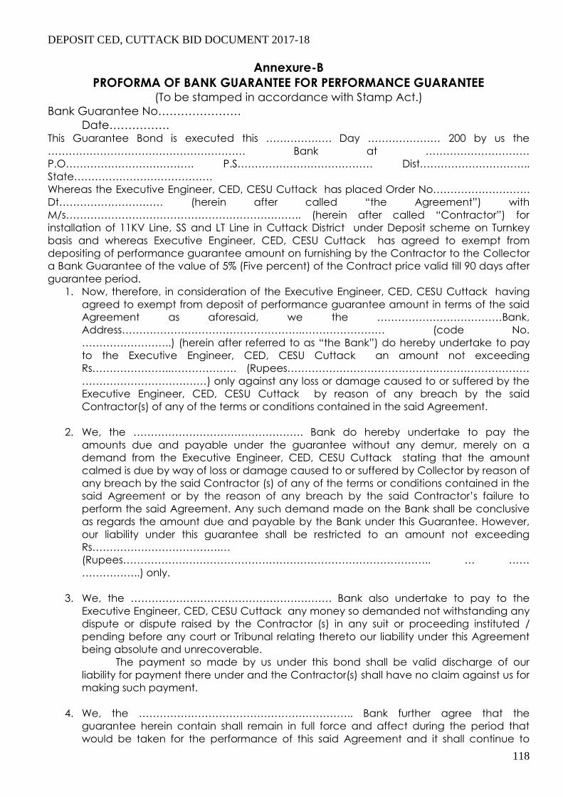
DEPOSIT CED, CUTTACK BID DOCUMENT 2017-18
118
Annexure-B
PROFORMA OF BANK GUARANTEE FOR PERFORMANCE GUARANTEE (To be stamped in accordance with Stamp Act.)
Bank Guarantee No………………….
Date……………. This Guarantee Bond is executed this ………………. Day ………………… 200 by us the
………………………………………………… Bank at …………………………
P.O………………………………. P.S………………………………… Dist…………………………..
State………………………………….
Whereas the Executive Engineer, CED, CESU Cuttack has placed Order No……………………….
Dt………………………… (herein after called “the Agreement”) with
M/s………………………………………………………….. (herein after called “Contractor”) for
installation of 11KV Line, SS and LT Line in Cuttack District under Deposit scheme on Turnkey
basis and whereas Executive Engineer, CED, CESU Cuttack has agreed to exempt from
depositing of performance guarantee amount on furnishing by the Contractor to the Collector
a Bank Guarantee of the value of 5% (Five percent) of the Contract price valid till 90 days after
guarantee period.
1. Now, therefore, in consideration of the Executive Engineer, CED, CESU Cuttack having
agreed to exempt from deposit of performance guarantee amount in terms of the said
Agreement as aforesaid, we the ………………………………Bank,
Address…………………………………………….…………………… (code No.
……………………..) (herein after referred to as “the Bank”) do hereby undertake to pay
to the Executive Engineer, CED, CESU Cuttack an amount not exceeding
Rs…………………..………………. (Rupees…………………………………….………………………
………………………………) only against any loss or damage caused to or suffered by the
Executive Engineer, CED, CESU Cuttack by reason of any breach by the said
Contractor(s) of any of the terms or conditions contained in the said Agreement.
2. We, the …………………………………………. Bank do hereby undertake to pay the
amounts due and payable under the guarantee without any demur, merely on a
demand from the Executive Engineer, CED, CESU Cuttack stating that the amount
calmed is due by way of loss or damage caused to or suffered by Collector by reason of
any breach by the said Contractor (s) of any of the terms or conditions contained in the
said Agreement or by the reason of any breach by the said Contractor’s failure to
perform the said Agreement. Any such demand made on the Bank shall be conclusive
as regards the amount due and payable by the Bank under this Guarantee. However,
our liability under this guarantee shall be restricted to an amount not exceeding
Rs……………………………….…
(Rupees…………………………………………………………………………….. … ……
……………..) only.
3. We, the …………………………………………………. Bank also undertake to pay to the
Executive Engineer, CED, CESU Cuttack any money so demanded not withstanding any
dispute or dispute raised by the Contractor (s) in any suit or proceeding instituted /
pending before any court or Tribunal relating thereto our liability under this Agreement
being absolute and unrecoverable.
The payment so made by us under this bond shall be valid discharge of our
liability for payment there under and the Contractor(s) shall have no claim against us for
making such payment.
4. We, the …………………………………………………….. Bank further agree that the
guarantee herein contain shall remain in full force and affect during the period that
would be taken for the performance of this said Agreement and it shall continue to

DEPOSIT CED, CUTTACK BID DOCUMENT 2017-18
119
remain in force endorsable till all the dues of the Collector under by virtue of the said
Agreement have been fully paid and its claim satisfied or discharged or till Collector
certifies that the terms and conditions of the said Agreement have been fully and
properly carried out by the said Contractor(s) and accordingly discharge this guarantee
and will not be revoked by us during the validity of the guarantee period.
Unless a demand or claim under this guarantee is made on us or with
…………………………………………………………. (Local Bank Name, Address and code
No.)…………………………………………………………………………, Cuttack in writing on or
before ……………………………………. (date) we shall be discharged from all liability
under this guarantee thereafter.
5. We, the ……………………………………………………………..Bank further agree that the
Collector shall have the fullest liberty without our consent and without affecting in any
manner our obligations hereunder to vary any of the terms and conditions of the said
Agreement or to extend time of performance by the said Contractor(s) and we shall not
be relieved from our liability by reason of any such variation or extension being granted
to the said contractor or for any forbearance act or omission on part of the Executive
Engineer, CED, CESU Cuttack or any indulgence by the Collector to the said
Contractor(s) or by any such matter or thing whatsoever which under the law relating to
sureties would but for this provisions have effect of so relieving us.
6. The Guarantee will not be discharged due to change in the name, style and constitution
of the Bank and or Contractor(s).
7. We, the …………………………………………………………… Bank lastly undertake not to
revoke this Guarantee during its currency except with the previous consent of the
Collector in writing.
Dated……………………………. The ………………………. Days of Two thousand
……………………
Not withstanding anything contained herein above.
i) Our liability under this Bank Guarantee shall not exceed Rs.
………………………………
(Rupees……………………………………………………………………………….) only.
ii) The Bank Guarantee shall be valid up to …………………………………only.
iii) We or our Bank at …………………………………..(Name & Address of the Local
Bank, Cuttack) are liable to pay the guaranteed amount depending on the filling
of claim and any part thereof under this Bank Guarantee only if you serve upon us
or our local Bank at ……………………, a written claim or demand and received by
us or by Local Branch at ………………………… on or before,
Dt…………………………… otherwise bank shall be discharged of all liabilities under
this guarantee thereafter.
For……………………………………………………………….
(indicate the name of the Bank)

DEPOSIT CED, CUTTACK BID DOCUMENT 2017-18
120
N.B.:-
1) Name of the Contractor:
2) No. & date of the purchaser order / agreement:
3) Name of the Bank:
4) Amount of the Bank Guarantee:
5) Name, Address and Code No. of the Local Branch:
6) Validity period or date upto which the agreement is valid:
7) Signature of the Constituent Authority of the Bank with seal:
8) Name & address of the Witnesses with signature:
9) The Bank Guarantee shall be accepted only after getting confirmation from the respective Bank
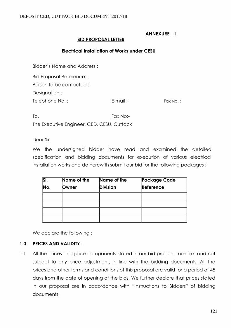
DEPOSIT CED, CUTTACK BID DOCUMENT 2017-18
121
ANNEXURE – I
BID PROPOSAL LETTER
Electrical Installation of Works under CESU
Bidder’s Name and Address :
Bid Proposal Reference :
Person to be contacted :
Designation :
Telephone No. : E-mail : Fax No. :
To, Fax No:-
The Executive Engineer, CED, CESU, Cuttack
Dear Sir,
We the undersigned bidder have read and examined the detailed
specification and bidding documents for execution of various electrical
installation works and do herewith submit our bid for the following packages :
Sl. Name of the Name of the Package Code
No. Owner Division Reference
We declare the following :
1.0 PRICES AND VALIDITY :
1.1 All the prices and price components stated in our bid proposal are firm and not
subject to any price adjustment, in line with the bidding documents. All the
prices and other terms and conditions of this proposal are valid for a period of 45
days from the date of opening of the bids. We further declare that prices stated
in our proposal are in accordance with “Instructions to Bidders” of bidding
documents.

DEPOSIT CED, CUTTACK BID DOCUMENT 2017-18
122
ii) We do hereby confirm that our bid prices as quoted in attached Schedules
include all import duties and levies including license fees lawfully payable by us
on imported items and other taxes, duties and levies applicable on bought – out
components, materials, equipment and other items and confirm that any such
taxes, duties and levies additionally payable shall be to our account.
1.3 We confirm that the Sales tax on Works Contract, Turnover Tax or any other similar
taxes under the GST Act, as applicable, are included in our quoted bid price and
there shall not be any liability on this account to the Owners. We understand that
Owners shall, deduct such taxes at source as per the rules and issue TDS
Certificate to us.
1.4 We confirm that, in our Bid Price, we have considered service tax in line with
lawful prevalent practice.
1.5 Price components of various items are indicated in the B.O.Q. for the
respective works. 1.6 We, having studied the bidding document in three volumes relating to taxes &
duties and hereby, declare that if any income tax, charge on income tax or any
other corporate tax is attracted under the law, we agree to pay the same.
1.7 We are aware that the Price schedules do not generally give a full description of the supplies
to be made and work to be performed under each item and we shall be deemed to have
read the Technical Specifications and other bidding documents and drawings to ascertain
the full scope of work included in each item while filling in the related and prices. We agree
that the entered rates and prices shall be deemed to include the full scope as aforesaid,
including overheads and profits.
1.8 We understand that in the price schedule, if there is discrepancy between the
unit price and total price, the same shall be corrected as per relevant provisions.
We declare that prices for items left blank in the schedules will be deemed to have been
included in other items. The TOTAL for each schedule and the TOTAL of Grand summary shall
be deemed to be the total price for executing the facilities and sections there of in
complete accordance with the contract, whether or not each item has been
priced.
2.0 CONSTRUCTION OF THE CONTRACT 3.1 We declare that we are making the offer on the basis of indivisible supply-cum-
Erection contract on a single source responsibility basis.
3.0 BID SECURITY( EMD)
We are enclosing BankDraft/BankGuarantee no.
………………..dated……amounting to Rs………… (Rupees
…………………….. only) issued by ………………….. Bank …….Branch,
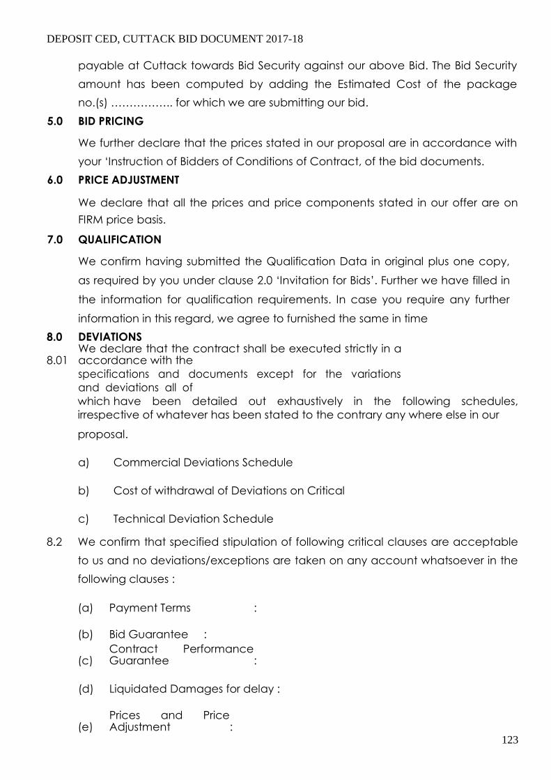
DEPOSIT CED, CUTTACK BID DOCUMENT 2017-18
123
payable at Cuttack towards Bid Security against our above Bid. The Bid Security
amount has been computed by adding the Estimated Cost of the package
no.(s) …………….. for which we are submitting our bid.
5.0 BID PRICING
We further declare that the prices stated in our proposal are in accordance with
your ‘Instruction of Bidders of Conditions of Contract, of the bid documents.
6.0 PRICE ADJUSTMENT
We declare that all the prices and price components stated in our offer are on
FIRM price basis. 7.0 QUALIFICATION
We confirm having submitted the Qualification Data in original plus one copy,
as required by you under clause 2.0 ‘Invitation for Bids’. Further we have filled in
the information for qualification requirements. In case you require any further
information in this regard, we agree to furnished the same in time 8.0 DEVIATIONS
8.01 We declare that the contract shall be executed strictly in a accordance with the
specifications and documents except for the variations
and deviations all of
which have been detailed out exhaustively in the following schedules,
irrespective of whatever has been stated to the contrary any where else in our
proposal.
a) Commercial Deviations Schedule
b) Cost of withdrawal of Deviations on Critical
c) Technical Deviation Schedule 8.2 We confirm that specified stipulation of following critical clauses are acceptable
to us and no deviations/exceptions are taken on any account whatsoever in the
following clauses :
(a) Payment Terms :
(b) Bid Guarantee :
(c) Contract Performance Guarantee :
(d) Liquidated Damages for delay :
(e) Prices and Price Adjustment :

DEPOSIT CED, CUTTACK BID DOCUMENT 2017-18
124
(f) Guarantee / Warrantees :
8.3 Further, we agree that the additional conditions, deviations, if any, found in our
bid proposal documents other than those stated in attached Deviation
Schedules, save that pertaining to any rebates offered, shall not be given effect
to. 9.0 ADDITIONAL INFORMATION
We have included with this proposal additional information listed. We further
confirm that such additional information does not imply any additional deviation
beyond those covered in appropriate schedules and in case of any
contradiction between these additional information and other provisions of Bid,
the latter prevail.
10.0 GURANTEE DECLARATION
We guarantee that the equipment offered shall meet the rating and
performance requirements stipulated in this specification. The Guarantee
Declaration which attract levy of liquidated damages for non-performance are
indicated in the relevant schedule.
12.0 WORK SCHEDULE
If this proposal is accepted by you, we agree to submit engineering data, provide
services and complete the entire work from time to time, in accordance with
schedule indicated in the proposal. We fully understand that the time schedule
stipulated in this proposal is the essence of the contract, if awarded. The
completion schedule of the various major key phases of the work is indicated in
the designated schedule.
13.0 CONTRACT PERFORMANCE GUARANTEE
We further agree that if our Bid is accepted we shall provide an irrevocable Bank
guarantee towards Contract Performance Guarantee, of value equivalent to five
percent (5%) of the Contract Price initially valid up to the end of ninety (90) days
after the end of the contract warranty period in the form of Bank Guarantee in
your favour within 15 (fifteen) days from the date of ‘Notice of Award of
Contract’ and enter into a formal agreement with you immediately thereafter.
14.0 CHECK LIST
We have included a check list duly filled in Schedule.
We, hereby declare that only the persons or firms interested in this proposal as
principals are named herein and that no other persons or firms other that those
If we are awarded the contract, and that this proposal is made without any
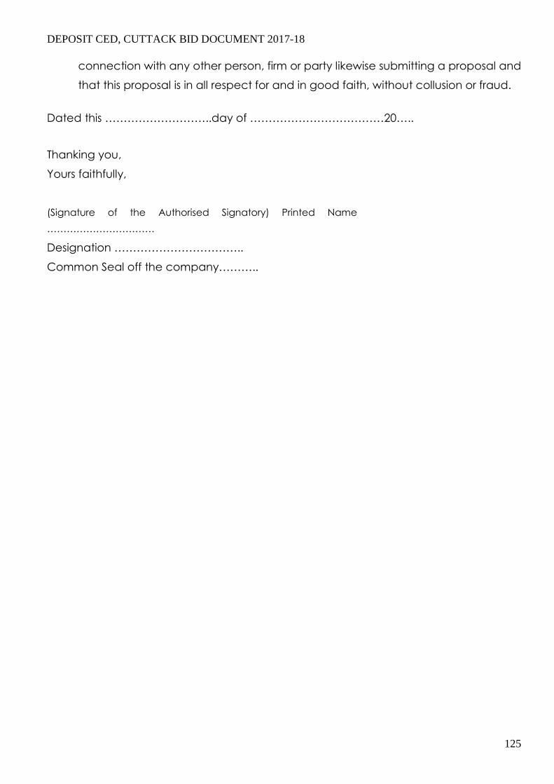
DEPOSIT CED, CUTTACK BID DOCUMENT 2017-18
125
connection with any other person, firm or party likewise submitting a proposal and
that this proposal is in all respect for and in good faith, without collusion or fraud.
Dated this ………………………..day of ………………………………20…..
Thanking you, Yours faithfully,
(Signature of the Authorised Signatory) Printed Name
…………………………… Designation …………………………….. Common Seal off the company………..

DEPOSIT CED, CUTTACK BID DOCUMENT 2017-18
126
ANNEXURE – II
DECLARATION FORM
To, The Executive Engineer,
CUTTACK ELECTRICAL DIVISION,JOBRA,CUTTACK
CENTRAL ELECTRICITY SUPPLY UTILITY OF ORISSA Cuttack- 07 Phone : 0671-2414052 Fax : 0671- 2414278
Web Site : www. cescoorissa.com . Sir,
Having examined the above specifications together with the Tender terms and
conditions referred to therein
1 – I / We the undersigned do hereby offer to supply the materials covered there on in
complete shape in all respects as per the rules entered in the attached contract
schedule of prices in the tender.
2 – I / We do hereby under take to have the materials delivered within the time
specified in the tender.
3 – I / We do hereby guarantee the technical particulars given in the tender
supported with necessary reports from concerned authorities.
4 – I / We do hereby certify to have purchased a copy of the tender specifications by
remitting Cash / Demand draft & this has been duly acknowledged by you in
your letter No…………Dt…………
5 – I / We do hereby agree to furnish the composite Bank Guarantee in the manner
specified / acceptable by CESU & for the sum as applicable to me / us within
fifteen days of issue of Letter of intent / Purchase Order , in the event of purchase
order being decided in my / our favour , failing which I / We clearly understand
that the said LOI / P.O. shall be liable to be withdrawn by the Owner.
Signed this…………….Day of……………………20…
Yours faithfully (Signature of Bidder with
Seal of Company) (This form should be duly filled up by the Bidder & submitted along with the original
copy of the Tender)
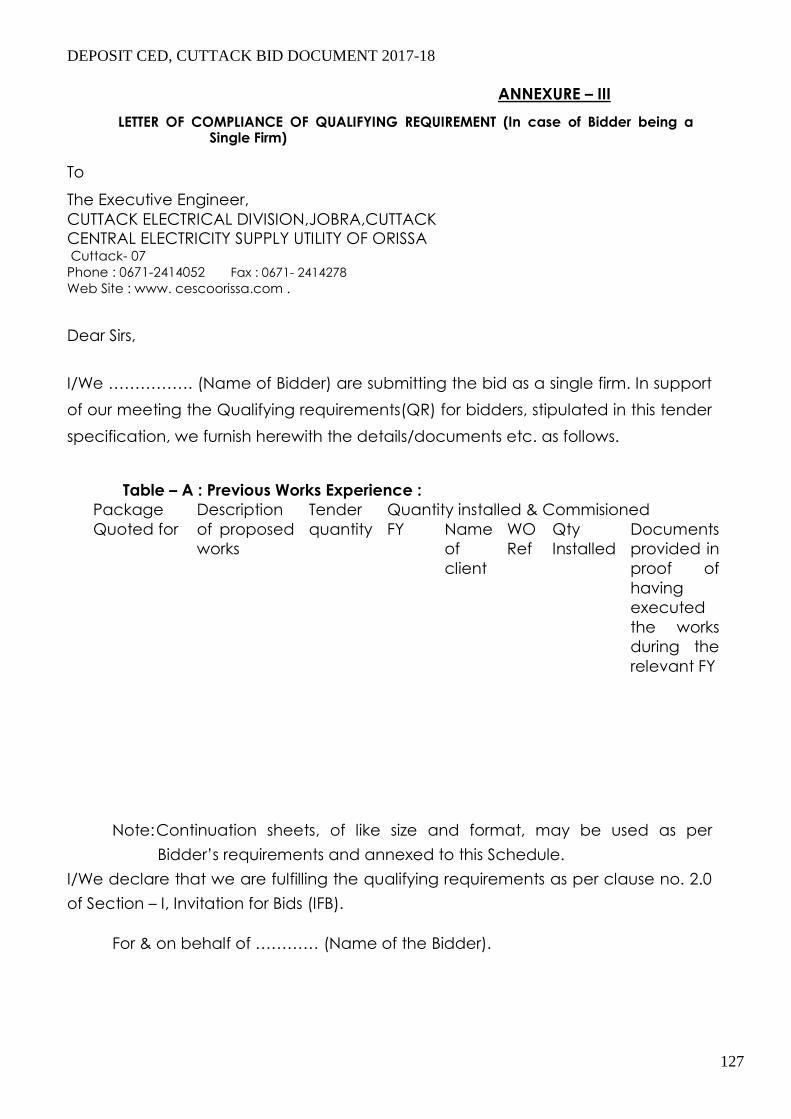
DEPOSIT CED, CUTTACK BID DOCUMENT 2017-18
127
ANNEXURE – III
LETTER OF COMPLIANCE OF QUALIFYING REQUIREMENT (In case of Bidder being a Single Firm)
To The Executive Engineer,
CUTTACK ELECTRICAL DIVISION,JOBRA,CUTTACK
CENTRAL ELECTRICITY SUPPLY UTILITY OF ORISSA Cuttack- 07 Phone : 0671-2414052 Fax : 0671- 2414278
Web Site : www. cescoorissa.com .
Dear Sirs,
I/We ……………. (Name of Bidder) are submitting the bid as a single firm. In support
of our meeting the Qualifying requirements(QR) for bidders, stipulated in this tender
specification, we furnish herewith the details/documents etc. as follows.
Table – A : Previous Works Experience :
Package
Quoted for
Description
of proposed
works
Tender
quantity
Quantity installed & Commisioned
FY Name
of
client
WO
Ref
Qty
Installed
Documents
provided in
proof of
having
executed
the works
during the
relevant FY
Note: Continuation sheets, of like size and format, may be used as per
Bidder’s requirements and annexed to this Schedule.
I/We declare that we are fulfilling the qualifying requirements as per clause no. 2.0
of Section – I, Invitation for Bids (IFB).
For & on behalf of ………… (Name of the Bidder).
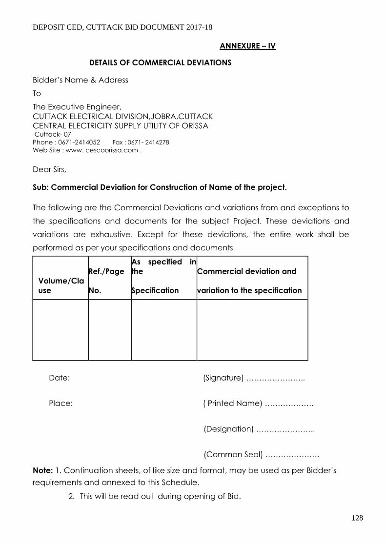
DEPOSIT CED, CUTTACK BID DOCUMENT 2017-18
128
ANNEXURE – IV
DETAILS OF COMMERCIAL DEVIATIONS
Bidder’s Name & Address To The Executive Engineer,
CUTTACK ELECTRICAL DIVISION,JOBRA,CUTTACK
CENTRAL ELECTRICITY SUPPLY UTILITY OF ORISSA Cuttack- 07 Phone : 0671-2414052 Fax : 0671- 2414278
Web Site : www. cescoorissa.com . Dear Sirs,
Sub: Commercial Deviation for Construction of Name of the project.
The following are the Commercial Deviations and variations from and exceptions to
the specifications and documents for the subject Project. These deviations and
variations are exhaustive. Except for these deviations, the entire work shall be
performed as per your specifications and documents
Ref./Page
As specified in
the Commercial deviation and
Volume/Cla
use No. Specification variation to the specification
Date: (Signature) …………………..
Place: ( Printed Name) ……………….
(Designation) …………………..
(Common Seal) ………………… Note: 1. Continuation sheets, of like size and format, may be used as per Bidder’s
requirements and annexed to this Schedule.
2. This will be read out during opening of Bid.
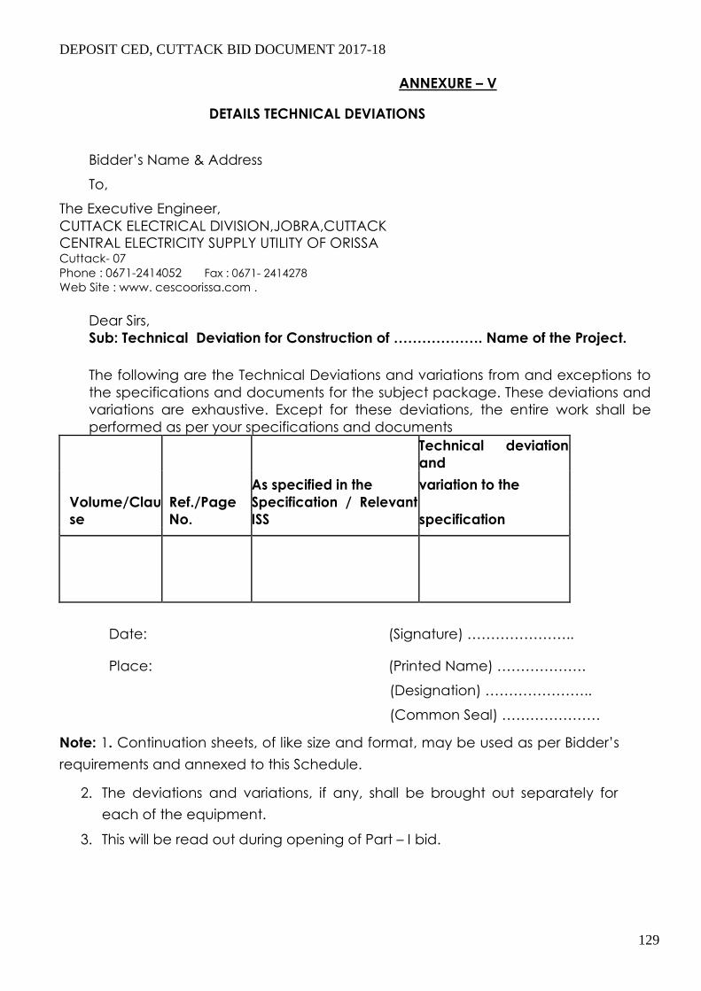
DEPOSIT CED, CUTTACK BID DOCUMENT 2017-18
129
ANNEXURE – V
DETAILS TECHNICAL DEVIATIONS
Bidder’s Name & Address
To, The Executive Engineer,
CUTTACK ELECTRICAL DIVISION,JOBRA,CUTTACK
CENTRAL ELECTRICITY SUPPLY UTILITY OF ORISSA Cuttack- 07 Phone : 0671-2414052 Fax : 0671- 2414278
Web Site : www. cescoorissa.com .
Dear Sirs,
Sub: Technical Deviation for Construction of ………………. Name of the Project.
The following are the Technical Deviations and variations from and exceptions to
the specifications and documents for the subject package. These deviations and
variations are exhaustive. Except for these deviations, the entire work shall be
performed as per your specifications and documents
Technical deviation
and
As specified in the variation to the
Volume/Clau
se
Ref./Page
No.
Specification / Relevant
ISS specification
Date: (Signature) …………………..
Place: (Printed Name) ……………….
(Designation) …………………..
(Common Seal) ………………… Note: 1. Continuation sheets, of like size and format, may be used as per Bidder’s
requirements and annexed to this Schedule.
2. The deviations and variations, if any, shall be brought out separately for
each of the equipment.
3. This will be read out during opening of Part – I bid.

DEPOSIT CED, CUTTACK BID DOCUMENT 2017-18
130
ANNEXURE – VI
ADDITIONAL INFORMATION
Bidder’s Name & Address
To The Executive Engineer,
CUTTACK ELECTRICAL DIVISION,JOBRA,CUTTACK
CENTRAL ELECTRICITY SUPPLY UTILITY OF ORISSA Cuttack- 07 Phone : 0671-2414052 Fax : 0671- 2414278
Web Site : www. cescoorissa.com .
Dear Sirs,
We have enclosed with our proposal the following additional information for
the subject, package.
Sl. No Brief description of Information Ref.& No.
Date: (Signature) …………………..
Place: (Printed Name) ……………….
(Designation) …………………..
(Common Seal) …………………
Note: Continuation sheets, of like size and format, may be used as per Bidder’s
requirements and annexed to this Schedule.

DEPOSIT CED, CUTTACK BID DOCUMENT 2017-18
131
ANNEXURE – VII
BOUGHT OUT & SUB CONTRACTED ITEMS
Bidder’s Name & Address To The Executive Engineer,
CUTTACK ELECTRICAL DIVISION,JOBRA,CUTTACK
CENTRAL ELECTRICITY SUPPLY UTILITY OF ORISSA Cuttack- 07 Phone : 0671-2414052 Fax : 0671- 2414278
Web Site : www. cescoorissa.com . Dear Sirs,
We hereby furnish the details of the items/sub-assemblies amounting to more than 10%
of our bid price, we propose to buy for the purpose of subject package Sl. No Item description Qty. Proposed Source of Supply
Be bought/
Sub-contracted
1. …………………… ………………………….. ………………………….. 2. ……………………. ……………………………. ………………………….. 3. …………………….. ……………………………. …………………………… 4…………………….. ……………………………. ……………………………. 5. ……………………. …………………………….. ……………………………. 6. …………………… …………………………….. ……………………………. 7. …………………… …………………………….. …………………………….
Date: (Signature) …………………..
Place: ( Printed Name) ……………….
(Designation) …………………..
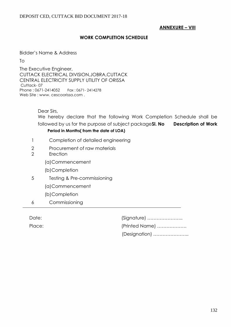
DEPOSIT CED, CUTTACK BID DOCUMENT 2017-18
132
ANNEXURE – VIII
WORK COMPLETION SCHEDULE
Bidder’s Name & Address To The Executive Engineer,
CUTTACK ELECTRICAL DIVISION,JOBRA,CUTTACK
CENTRAL ELECTRICITY SUPPLY UTILITY OF ORISSA Cuttack- 07 Phone : 0671-2414052 Fax : 0671- 2414278
Web Site : www. cescoorissa.com .
Dear Sirs,
We hereby declare that the following Work Completion Schedule shall be
followed by us for the purpose of subject packageSl. No Description of Work
Period in Months( from the date of LOA)
1 Completion of detailed engineering
2 Procurement of raw materials
2 Erection
(a) Commencement
(b) Completion
5 Testing & Pre-commissioning
(a) Commencement
(b) Completion
6 Commissioning
Date: (Signature) …………………..
Place: (Printed Name) ……………….
(Designation) …………………..
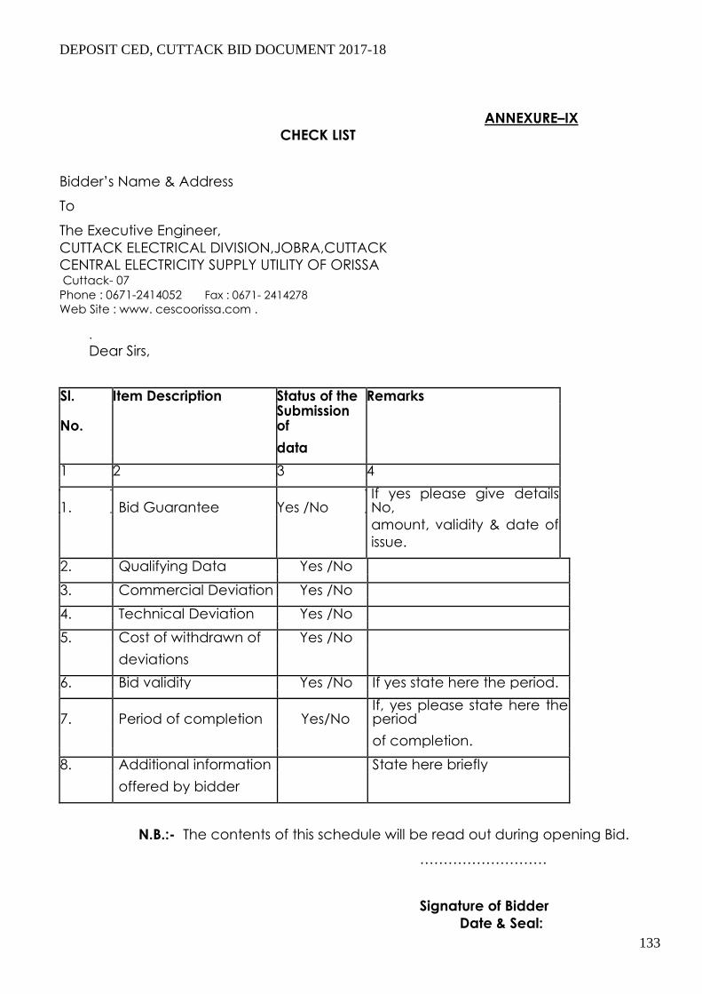
DEPOSIT CED, CUTTACK BID DOCUMENT 2017-18
133
ANNEXURE–IX
CHECK LIST
Bidder’s Name & Address To The Executive Engineer,
CUTTACK ELECTRICAL DIVISION,JOBRA,CUTTACK
CENTRAL ELECTRICITY SUPPLY UTILITY OF ORISSA Cuttack- 07 Phone : 0671-2414052 Fax : 0671- 2414278
Web Site : www. cescoorissa.com .
.
Dear Sirs, Sl. Item Description Status of the Remarks
No. Submission of
data
1 2 3 4
1. Bid Guarantee Yes /No If yes please give details No,
amount, validity & date of
issue.
2. Qualifying Data Yes /No
3. Commercial Deviation Yes /No
4. Technical Deviation Yes /No
5. Cost of withdrawn of Yes /No
deviations
6. Bid validity Yes /No If yes state here the period.
7. Period of completion Yes/No If, yes please state here the period
of completion.
8. Additional information State here briefly
offered by bidder
N.B.:- The contents of this schedule will be read out during opening Bid.
………………………
Signature of Bidder
Date & Seal:

DEPOSIT CED, CUTTACK BID DOCUMENT 2017-18
134
N.B :-
1. The bid guarantee one original and one copy shall be furnished in two
separate sealed envelope appropriately superscribed thereon.
2. All Schedules pertaining to prices (originals ) shall be furnished in a
sealed envelope duly superscribed thereon. Similarly one set of copies
of such schedules shall be given in a separate sealed envelope.
3. All other schedules, one set original and another copy shall be
submitted in two separate sealed envelope
Date: (Signature) …………………..
Place: (Printed Name) ……………….
(Designation) …………………..
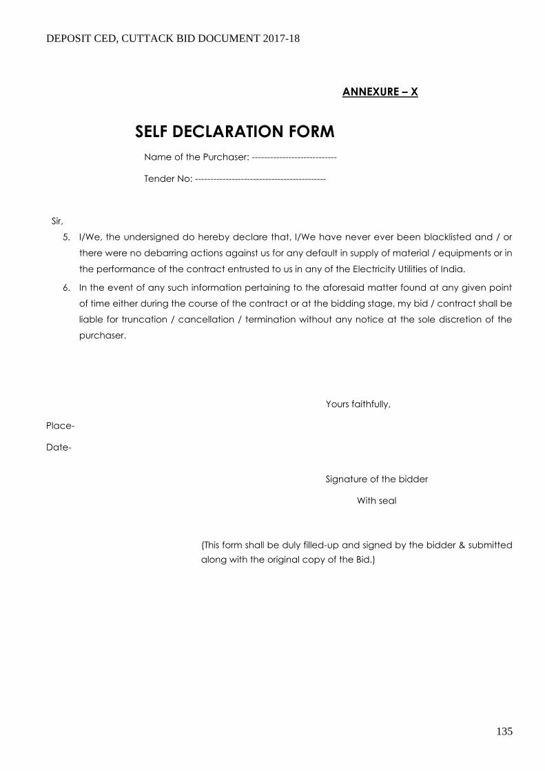
DEPOSIT CED, CUTTACK BID DOCUMENT 2017-18
135
ANNEXURE – X
SELF DECLARATION FORM
Name of the Purchaser: ----------------------------
Tender No: -------------------------------------------
Sir,
5. I/We, the undersigned do hereby declare that, I/We have never ever been blacklisted and / or
there were no debarring actions against us for any default in supply of material / equipments or in
the performance of the contract entrusted to us in any of the Electricity Utilities of India.
6. In the event of any such information pertaining to the aforesaid matter found at any given point
of time either during the course of the contract or at the bidding stage, my bid / contract shall be
liable for truncation / cancellation / termination without any notice at the sole discretion of the
purchaser.
Yours faithfully,
Place- Date-
Signature of the bidder
With seal
(This form shall be duly filled-up and signed by the bidder & submitted
along with the original copy of the Bid.)

DEPOSIT CED, CUTTACK BID DOCUMENT 2017-18
136
]
TENDER CALL NOTICE
CENTRAL ELECTRICITY SUPPLY UTILITY OF ORISSA (Formerly CESCO)
Registered Office : IDCO TOWERS, (IInd Floor), Janapath, Bhubaneswar – 751 022
OFFICE OF THE EXECUTIVE ENGINEER(ELECT.), CUTTACK ELECTRICAL DIVISION, CUTTACK
E mail:- [email protected], : 0671-2414052, 9437011317, Fax : 0671 – 2414278
Tender notice No-…………. Date-…………
The Executive Engineer (Elect.) C.E.D Cuttack for and on behalf of CESU, invites sealed bids
in duplicate from empanelled Electrical Contractors having valid H.T license issued by E.L.B.O
& executed similar natures of works for electrification with up to date VAT clearance & PAN
for erection, installation, testing, commissioning etc of 11 KV O.H.H.T line, DP mounted 11/0.4
KV electrical Sub- Station , L.T line etc. who comply to the terms and conditions for the
following works to be executed in the licensed area of Cuttack Electrical Division, Jobra
Cuttack under Niali-1 electrical section of CESU in the Cuttack District of the state of Odisha as
per the place mentioned here under 100% deposit work on partly turnkey basis.
Brief Description of the work: (1) Construction of 11 KV lines,Sub-Stations and L.T lines
Sl.No Name of the work
Apprcx. Estd. Cost
(Rs in Lakhs)
Cost of tender paper (Non
refundable) in Rupees
Class of contractor
EMD
required
in Rupees
Last date/time
for submission
of bids.
1 Construction of Sub-station &
LT lines towards electrification
of village/hamlet Purba
Khanda Alok Nagar (In front
of Binapani Dash House near
Delta) under 100% deposit
work on partly turnkey
basis in Niali-1 section.
3.96
2000.00+5
% VAT
HT
license
holder
3968.00
23.12.2016
At-2.30PM
TERMS AND CONDITION –
1. Further details(if required) can be had from the office of the undersigned during office hours. The
work put to tender will be executed depending on the availability of fund
2. EMD in shape of NSC/post office saving pass book/Cash/Bank draft in any Nationalized
Bank/post office duly pledged in favors of “Manager (Elect.) C.E.D Cuttack” should be given with
tender as mentioned against the work. The offers without valid EMD/Part EMD will be out rightly
rejected.

DEPOSIT CED, CUTTACK BID DOCUMENT 2017-18
137
7. The sale of bid documents will be available for sale in the office of the undersigned from dated
16.12.2016 To 23.12.2016 during office working hours and up to 2:00 P.M on date- 23.12.2016
on payment of cost of tender paper (Non refundable). The complete bid documents will be
received up to 2:30 P.M on date 23.12.2016. in the office of the undersigned and will be opened
on date 23.12.2016 at 4.00 P.M at C.E.D Jobra Cuttack . Participants or their authorized agents
may remain present during opening of tender.
8. Eligibility criteria :
e) The intending tender should show up-to-date valid HT contractors Registration certificate,
PAN card, VAT clearance certificate in form of VAT-612.
f) The following documents, certificates should be furnished along with tender papers failing
which the tender is liable for rejection.
v. The bidder should submit the EMD rounded to nearest next hundred rupees.
vi. The bidder Quoting for more than one work is required to submit the bid documents
separately i.e one envelope for each work with individual EMD. Deposit of EMD in
consolidated manner is liable for rejection.
vii. Attested copy of contractor registration/ licensed / labour license certificate
viii. Attested copy of valid pan card, VAT clearance certificate
g) All documents should be produced in very clear and legible manner duly self attested and
free from any ambiguity and all documents should be signed by the agency as per specimen
signature in the license copy. In case of any deviation the tender will be liable for rejection.
h) The completed documents can be dispatched by Regd. Post/ speed post to the undersigned
which should reach on or before schedule date and time of receipt of tender. The department
will not be held responsible for the postal delay in delivery of the documents or non- receipt of
the same or any loss, theft and part DTCN documents received from the postal.
9. Authority reserves all rights to reject any or all tenders without assigning any reason thereof.
10. All correspondence with regard to the above shall be made to the following address :
Manager (Elect.) CESU, Cuttack Electrical Division,Jobra, Cuttack, Pin- 753007, ODISHA Tel. No- 0671-2414052, Mobile- 9437011317, Fax : 0671 – 2414278
Executive Engineer(Elect.)
C.E.D Cuttack
CC to- 1. The Superintending Engineer, Electrical Circle, Cuttack for kind information and necessary
action. 2. The E.E (Elect.), AED, Athagarh/ CDD-II Cuttack/ SED, Salipur for information. 3. The Sr. General Manager (Tech.), CESU HQrs. for kind information. 4. Notice Board of this office/ AM (Finance)/ Cashier, of this office for information.

DEPOSIT CED, CUTTACK BID DOCUMENT 2017-18
138
Executive Engineer(Elect.)