central controllers - amazon web...
TRANSCRIPT

central controllers
NetLinx NI-Series Controllers
For Small or Medium Rooms (7, 8 or 15 Control Ports) ..............
356 – 364
For Large or Multiple Rooms (30 or 31 Control Ports) 365 – 373
NetLinx Communication Gateways
(utilizes KNX communication protocol) .................................... 375
NetLinx Cards and Shells
(select the right card for the application) ......................... 374, 376
Accessories ...................................................................... 377 – 383

354 US SALES AND SUPPORT 800.222.0193 • INTERNATIONAL SALES AND SUPPORT +1.469.624.7400 • www.amx.com© January 2013 AMX. All rights reserved. AMX does not assume responsibility for any errors or omissions.
IntroDUctIon central controllers
RENOWNED RELIABILITYEnsuring Every Command is Carried Out the First Time
AMX Central Controllers are synonymous with reliability, flexibility, and security. As the brains of every AMX control system,
the NetLinx family of products are designed to be a true IT standards-based, secure solution with remote monitoring and
management using a client-server architecture interfacing with the AMX Resource Management Suite software applications.
Furthermore, our command architecture supports net-centric management of devices – which simplifies equipment
management and maintenance and lowers total cost of ownership. In fact, they use the same VxWorks Real-Time Operating
System to control space shuttles and defense systems.
SYSTEM DIAGRAM
NetLinx Central Controllers can control large numbers of AMX
and third party devices via RS232, IP, IR and Contact Closure.
3553000 RESEARCH DRIVE, R ICHARDSON, TX 75082 • 800.222.0193 • 469.624.7153 fax • TECHNICAL SUPPORT 800.932.6993© January 2013 AMX. All rights reserved. AMX does not assume responsibility for any errors or omissions.
IntroDUctIon central controllers
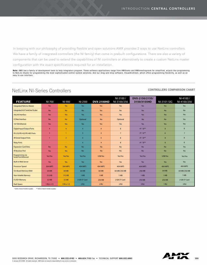
In keeping with our philosophy of providing flexible and open solutions AMX provides 2 ways to use NetLinx controllers.
We have a family of integrated controllers (the NI family) that come in prebuilt configurations. There are also a variety of
components that can be used to extend the capabilities of NI controllers or alternatively to create a custom NetLinx master
configuration with the exact specifications required for an installation.
Note: AMX has a fami ly o f deve lopment too ls to he lp in tegra tors program. These sof tware app l ica t ions range f rom AMXhome and AMXmeet ingroom for s impl i f ied , wizard- l ike programming to NetL inx Stud io fo r programming the most soph is t ica ted cont ro l sys tem so lu t ions . And our drag-and-drop sof tware , V isua lArch i tec t , wh ich o f fe rs programming f lex ib i l i t y, as we l l as an easy to use in ter face .
NetLinx NI-Series Controllers CONTROLLERS COMPARISON CHART
central controllers
356 US SALES AND SUPPORT 800.222.0193 • INTERNATIONAL SALES AND SUPPORT +1.469.624.7400 • www.amx.com© January 2013 AMX. All rights reserved. AMX does not assume responsibility for any errors or omissions.
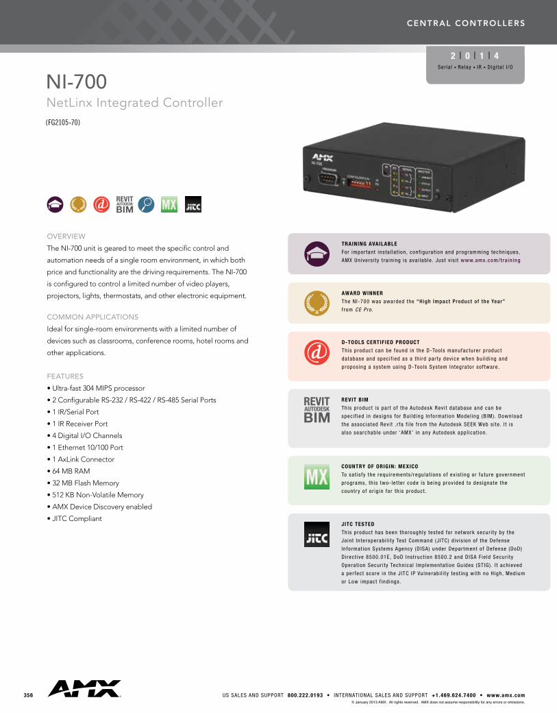
OVERVIEW
The NI-700 unit is geared to meet the specific control and
automation needs of a single room environment, in which both
price and functionality are the driving requirements. The NI-700
is configured to control a limited number of video players,
projectors, lights, thermostats, and other electronic equipment.
COMMON APPLICATIONS
Ideal for single-room environments with a limited number of
devices such as classrooms, conference rooms, hotel rooms and
other applications.
FEATURES
•Ultra-fast304MIPSprocessor
•2ConfigurableRS-232/RS-422/RS-485SerialPorts
•1IR/SerialPort
•1IRReceiverPort
•4DigitalI/OChannels
•1Ethernet10/100Port
•1AxLinkConnector
•64MBRAM
•32MBFlashMemory
•512KBNon-VolatileMemory
•AMXDeviceDiscoveryenabled
•JITCCompliant
NI-700NetLinx Integrated Controller (FG2105-70)
2 | 0 | 1 | 4Ser ia l n Re lay n IR n Dig i ta l I /O
AWARD WINNER
The N I-700 was awarded the “High Impact Product o f the Year”
f rom CE Pro .
D-TOOLS CERTIFIED PRODUCT
This product can be found in the D-Too ls manufacturer product
da tabase and spec i f ied as a th i rd par ty dev ice when bu i ld ing and
propos ing a sys tem us ing D-Too ls Sys tem In tegra tor so f tware .
COUNTRY OF ORIGIN: MEXICO
To sa t is fy the requ i rements / regu la t ions o f ex is t ing or fu ture government
programs, th is two- le t te r code is be ing prov ided to des igna te the
count r y o f o r ig in fo r th is product .
TRAINING AVAILABLE
For impor tant ins ta l la t ion , conf igura t ion and programming techn iques ,
AMX Un ivers i ty t ra in ing is ava i lab le . Jus t v is i t www.amx.com/tra in ing
REVIT BIM
This product i s par t o f the Autodesk Rev i t da tabase and can be
spec i f ied in des igns fo r Bu i ld ing In format ion Mode l ing (B IM) . Download
the assoc ia ted Rev i t . r fa f i l e f rom the Autodesk SEEK Web s i te . I t i s
a lso searchab le under ‘AMX’ in any Autodesk app l ica t ion .
JITC TESTED
This product has been thorough ly tes ted fo r network secur i ty by the
Jo in t In teroperab i l i t y Test Command (J ITC) d iv is ion o f the Defense
In format ion Systems Agency (D ISA) under Depar tment o f Defense (DoD)
D i rec t ive 8500.01E, DoD Ins t ruc t ion 8500.2 and D ISA Fie ld Secur i ty
Opera t ion Secur i ty Techn ica l Implementa t ion Gu ides (ST IG) . I t ach ieved
a per fec t score in the J ITC IP Vu lnerab i l i t y tes t ing wi th no H igh, Medium
or Low impact f ind ings .
central controllers
3573000 RESEARCH DRIVE, R ICHARDSON, TX 75082 • 800.222.0193 • 469.624.7153 fax • TECHNICAL SUPPORT 800.932.6993© January 2013 AMX. All rights reserved. AMX does not assume responsibility for any errors or omissions.
nI -700 central controllers
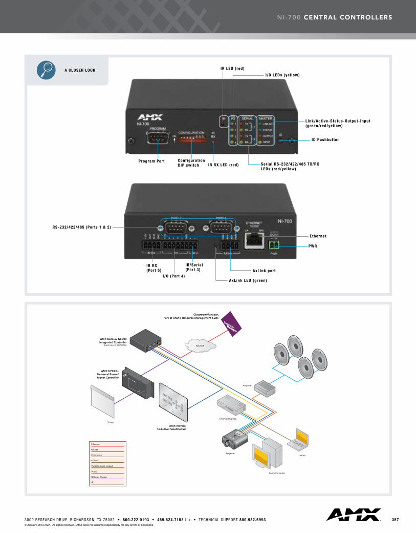
A CLOSER LOOK
RS-232/422/485 (Ports 1 & 2)
Ethernet
PWR
AxLink port
AxLink LED (green)
IR/Ser ia l(Port 3)
I /O (Port 4)
IR RX(Port 5)
Program PortIR RX LED (red) Ser ia l RS-232/422/485 TX/RX
LEDs ( red/yel low)
IR LED (red)
I /O LEDs (ye l low)
ID Pushbutton
Link/Act ive-Status-Output- Input (green/red/yel low)
Conf igurat ion DIP switch

358 US SALES AND SUPPORT 800.222.0193 • INTERNATIONAL SALES AND SUPPORT +1.469.624.7400 • www.amx.com© January 2013 AMX. All rights reserved. AMX does not assume responsibility for any errors or omissions.
RECOMMENDED ACCESSORIES DESCRIPTION PART # PAGE #
IRX-PP38 Plasma Proof IR Sensor (FG460) 348PSN6.5 6.5 Amp Power Supply (FG423-41) 415 PSN4.4 4.4 Amp Power Supply (FG423-45) 414AC-RK Accessory Rack Kit (FG515) 410AC-SMB Surface Mounting Bracket (FG525) 412CC-232 RS232/422 Cables (FG10-752-04) 420CC-NIRC IR Cables (FG10-000-11) 420
SPECIFICATIONS
DIMENSIONS (HWD)
• 1 9/16” x 5 9/16” x 5 1/8” (4.01 cm x 14.10 cm x 13.00 cm)• RU: 1
WEIGHT
1.30 lbs (590 g)
POWER
• 280 mA @ 12 VDC• Power requirements are usage dependant
ENCLOSURE
Metal with black matte finish
ONBOARD MASTER
304 MIPS
CERTIFICATIONS
FCC Part 15 Class B, CE, and IEC 60950
FRONT PANEL COMPONENTS
• Program Port• Configuration DIP Switch: Sets the communication parameters for the Program port• IR RX LED: Red LED lights when IR data is being received via the rear IR RX port• IR LED: Red LED lights during the transmission of IR or Serial data via the rear IR port• I/O LEDs: Four yellow LEDs light when the rear I/O channels 1 - 4 are active. LED indicator for each I/O port reflects the state of that particular port• Serial LEDs• LINK/ACT: Green LED lights when the Ethernet cable is connected and an active link is established. This LED also blinks when receiving Ethernet data packets• Status: Green LED lights when the Controller is programmed and communicating properly• Output: Red LED lights when the Controller transmits data, sets channels sends data strings, etc.• Input: Yellow LED lights when the Controller receives data from button pushes, strings, commands, channel levels, etc.• ID Pushbutton: Sets the NetLinx ID (Device only) assignment for the device
REAR PANEL CONNECTORS
• RS-232/422/485 (Ports 1 & 2)• IR RX (Port 5)• Digital I/O (Port 4)• IR/Serial (Port 3)• AxLink LED• AxLink Port: 4-pin 3.5 mm mini-Phoenix (male) connector provides data and power to external control devices• Ethernet Port: RJ-45 port for 10/100 Mbps communication. LEDs show communication activity, connection status, speeds, and mode information: - SPD (speed) - Yellow LED lights On when the connection speed is 100 Mbps and turns Off when the speed is 10 Mbps. - L/A (link/activity) - Green LED lights On when the Ethernet cables are connected and terminated correctly, and blinks when receiving Ethernet data packets.• Power Port
ENVIRONMENTAL
• Operating Temperature: 0º C (32º F) to 50º C (122º F)• Operating Humidity: 20% to 85% RH• Heat Dissipation (Typical): 11.5 BTU/hr
INCLUDED ACCESSORIES
• 2-pin 3.5 mm mini-Phoenix female PWR connector (41-5025)• 4-pin 3.5 mm mini-Phoenix female connector (41-5047)• 6-pin 3.5 mm mini-Phoenix female I/O connector (41-5063)• CC-NIRC IR Emitter
nI -700 central controllers

central controllers
3593000 RESEARCH DRIVE, R ICHARDSON, TX 75082 • 800.222.0193 • 469.624.7153 fax • TECHNICAL SUPPORT 800.932.6993© January 2013 AMX. All rights reserved. AMX does not assume responsibility for any errors or omissions.
NI-900NetLinx Integrated Controller (FG2105-90)
1 | 0 | 3 | 4Ser ia l n Re lay n IR n Dig i ta l I /O
OVERVIEW
The NI-900 unit is designed to control and automate a variety of
devices in single rooms or multiple small rooms and is capable
of supporting devices with a variety of communication formats. It
is configured to control a limited number of lights, thermostats,
video displays and other equipment.
COMMON APPLICATION
Perfect for single rooms or two or more small rooms with a limited
numberofdevicessuchashometheaters,MDUs,hotelrooms
and other environments.
FEATURES
•1ConfigurableRS-232/RS-422/RS-485Serialport
•3IR/Serialports
•1IRReceiverPort
•4DigitalI/Oports
•2CommunicationNetworks:AxLinkandEthernet(TCP/IP)
•304MIPSprocessorspeed
•64MBRAM
•32MBMemory
•512KBNon-VolatileMemory
•AMXDeviceDiscoveryenabled
•JITCCompliant
D-TOOLS CERTIFIED PRODUCT
This product can be found in the D-Too ls manufacturer product
da tabase and spec i f ied as a th i rd par ty dev ice when bu i ld ing and
propos ing a sys tem us ing D-Too ls Sys tem In tegra tor so f tware .
COUNTRY OF ORIGIN: MEXICO
To sa t is fy the requ i rements / regu la t ions o f ex is t ing or fu ture government
programs, th is two- le t te r code is be ing prov ided to des igna te the
count r y o f o r ig in fo r th is product .
TRAINING AVAILABLE
For impor tant ins ta l la t ion , conf igura t ion and programming techn iques ,
AMX Un ivers i ty t ra in ing is ava i lab le . Jus t v is i t www.amx.com/tra in ing
REVIT BIM
This product i s par t o f the Autodesk Rev i t da tabase and can be
spec i f ied in des igns fo r Bu i ld ing In format ion Mode l ing (B IM) . Download
the assoc ia ted Rev i t . r fa f i l e f rom the Autodesk SEEK Web s i te . I t i s
a lso searchab le under ‘AMX’ in any Autodesk app l ica t ion .
JITC TESTED
This product has been thorough ly tes ted fo r network secur i ty by the
Jo in t In teroperab i l i t y Test Command (J ITC) d iv is ion o f the Defense
In format ion Systems Agency (D ISA) under Depar tment o f Defense (DoD)
D i rec t ive 8500.01E, DoD Ins t ruc t ion 8500.2 and D ISA Fie ld Secur i ty
Opera t ion Secur i ty Techn ica l Implementa t ion Gu ides (ST IG) . I t ach ieved
a per fec t score in the J ITC IP Vu lnerab i l i t y tes t ing wi th no H igh, Medium
or Low impact f ind ings .

360 US SALES AND SUPPORT 800.222.0193 • INTERNATIONAL SALES AND SUPPORT +1.469.624.7400 • www.amx.com© January 2013 AMX. All rights reserved. AMX does not assume responsibility for any errors or omissions.
A CLOSER LOOK
RS-232/422/485 (Port 1) Ethernet
PWRAxLink port
AxLink LED (green)
IR/Ser ia l(Ports 2-4)
I /O (Port 5)Program Port Conf igurat ion
DIP switch
IR RX LED (red)
IR LED (red)
I /O LEDs (ye l low)
ID Pushbutton
Ser ia l RS-232/422/485 TX/RX LED (red/yel low)
Link/Act ive-Status-Output- Input (green/red/yel low)
IR RX(Port 6)
nI -900 central controllers
3613000 RESEARCH DRIVE, R ICHARDSON, TX 75082 • 800.222.0193 • 469.624.7153 fax • TECHNICAL SUPPORT 800.932.6993© January 2013 AMX. All rights reserved. AMX does not assume responsibility for any errors or omissions.
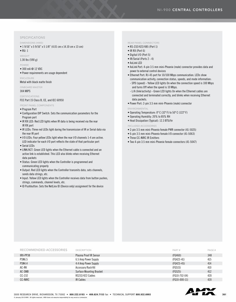
RECOMMENDED ACCESSORIES DESCRIPTION PART # PAGE #
IRX-PP38 Plasma Proof IR Sensor (FG460) 348PSN6.5 6.5 Amp Power Supply (FG423-41) 415 PSN4.4 4.4 Amp Power Supply (FG423-45) 414AC-RK Accessory Rack Kit (FG515) 410AC-SMB Surface Mounting Bracket (FG525) 412CC-232 RS232/422 Cables (FG10-752-04) 420CC-NIRC IR Cables (FG10-000-11) 420
SPECIFICATIONS
DIMENSIONS (HWD)
• 1 9/16” x 5 9/16” x 5 1/8” (4.01 cm x 14.10 cm x 13 cm)• RU: 1
WEIGHT
1.30 lbs (590 g)
POWER
• 300 mA @ 12 VDC• Power requirements are usage dependent
ENCLOSURE
Metal with black matte finish
ONBOARD MASTER
304 MIPS
CERTIFICATIONS
FCC Part 15 Class B, CE, and IEC 60950
FRONT PANEL COMPONENTS
• Program Port• Configuration DIP Switch: Sets the communication parameters for the Program port• IR RX LED: Red LED lights when IR data is being received via the rear IR RX port• IR LEDs: Three red LEDs light during the transmission of IR or Serial data via the rear IR port• I/O LEDs: Four yellow LEDs light when the rear I/O channels 1-4 are active. LED indicator for each I/O port reflects the state of that particular port• Serial LEDs• LINK/ACT: Green LED lights when the Ethernet cable is connected and an active link is established. This LED also blinks when receiving Ethernet data packets• Status: Green LED lights when the Controller is programmed and communicating properly• Output: Red LED lights when the Controller transmits data, sets channels, sends data strings, etc.• Input: Yellow LED lights when the Controller receives data from button pushes, strings, commands, channel levels, etc.• ID Pushbutton: Sets the NetLinx ID (Device only) assignment for the device
REAR PANEL CONNECTORS
• RS-232/422/485 (Port 1)• IR RX (Port 6)• Digital I/O (Port 5)• IR/Serial (Ports 2 - 4) • AxLink LED• AxLink Port: 4-pin 3.5 mm mini-Phoenix (male) connector provides data and power to external control devices• Ethernet Port: RJ-45 port for 10/100 Mbps communication. LEDs show communication activity, connection status, speeds, and mode information: - SPD (speed) - Yellow LED lights On when the connection speed is 100 Mbps and turns Off when the speed is 10 Mbps. - L/A (link/activity) - Green LED lights On when the Ethernet cables are connected and terminated correctly, and blinks when receiving Ethernet data packets.• Power Port: 2-pin 3.5 mm mini-Phoenix (male) connector
ENVIRONMENTAL
• Operating Temperature: 0º C (32º F) to 50º C (122º F)• Operating Humidity: 20% to 85% RH• Heat Dissipation (Typical): 12.3 BTU/hr
INCLUDED ACCESSORIES
• 2-pin 3.5 mm mini-Phoenix female PWR connector (41-5025)• 6-pin 3.5 mm mini-Phoenix female I/O connector (41-5063)• Three CC-NIRC IR Emitters• Two 4-pin 3.5 mm mini-Phoenix female connectors (41-5047)
nI -900 central controllers

central controllers
362 US SALES AND SUPPORT 800.222.0193 • INTERNATIONAL SALES AND SUPPORT +1.469.624.7400 • www.amx.com© January 2013 AMX. All rights reserved. AMX does not assume responsibility for any errors or omissions.
OVERVIEW
TheNI-2100isidealforcontrolandautomationofmedium-sized
roomsandmulti-roomapplications.TheNI-2100has64MB
ofonboardRAMandisDeviceDiscoveryenabledtosimplify
programmingbystandardizingdeviceandfunctiondefinitions,
default touch panel button assignments, and control and
feedbackmethods.
COMMON APPLICATION
TheNI-2100isagoodfitformedium-sizedroomsormulti-room
applications in home theaters, whole homes, hotel rooms and
other environments.
FEATURES
•3ConfigurableRS-232/RS-422/RS-485Serialports
•4Relays
•4IR/Serialports
•4DigitalI/Oports
•2CommunicationNetworks:AxLinkandEthernet(TCP/IP)
•404MIPSprocessorspeed
•64MBRAM
•2GBCompactFlash(upgradeableto4G)
•1MBNon-VolatileMemory
•AMXDeviceDiscoveryenabled
•JITCCompliant
NI-2100NetLinx Integrated Controller NI-2100 Controller (FG2105-04)
NI-2100 Controller with ICSNet (FG2105-14)
3 | 4 | 4 | 4Ser ia l n Re lay n IR n Dig i ta l I /O
D-TOOLS CERTIFIED PRODUCT
This product can be found in the D-Too ls manufacturer product
da tabase and spec i f ied as a th i rd par ty dev ice when bu i ld ing and
propos ing a sys tem us ing D-Too ls Sys tem In tegra tor so f tware .
COUNTRY OF ORIGIN: MEXICO
To sa t is fy the requ i rements / regu la t ions o f ex is t ing or fu ture government
programs, th is two- le t te r code is be ing prov ided to des igna te the
count r y o f o r ig in fo r th is product .
TRAINING AVAILABLE
For impor tant ins ta l la t ion , conf igura t ion and programming techn iques ,
AMX Un ivers i ty t ra in ing is ava i lab le . Jus t v is i t www.amx.com/tra in ing
REVIT BIM
This product i s par t o f the Autodesk Rev i t da tabase and can be
spec i f ied in des igns fo r Bu i ld ing In format ion Mode l ing (B IM) . Download
the assoc ia ted Rev i t . r fa f i l e f rom the Autodesk SEEK Web s i te . I t i s
a lso searchab le under ‘AMX’ in any Autodesk app l ica t ion .
JITC TESTED
This product has been thorough ly tes ted fo r network secur i ty by the
Jo in t In teroperab i l i t y Test Command (J ITC) d iv is ion o f the Defense
In format ion Systems Agency (D ISA) under Depar tment o f Defense (DoD)
D i rec t ive 8500.01E, DoD Ins t ruc t ion 8500.2 and D ISA Fie ld Secur i ty
Opera t ion Secur i ty Techn ica l Implementa t ion Gu ides (ST IG) . I t ach ieved
a per fec t score in the J ITC IP Vu lnerab i l i t y tes t ing wi th no H igh, Medium
or Low impact f ind ings .
central controllers
3633000 RESEARCH DRIVE, R ICHARDSON, TX 75082 • 800.222.0193 • 469.624.7153 fax • TECHNICAL SUPPORT 800.932.6993© January 2013 AMX. All rights reserved. AMX does not assume responsibility for any errors or omissions.
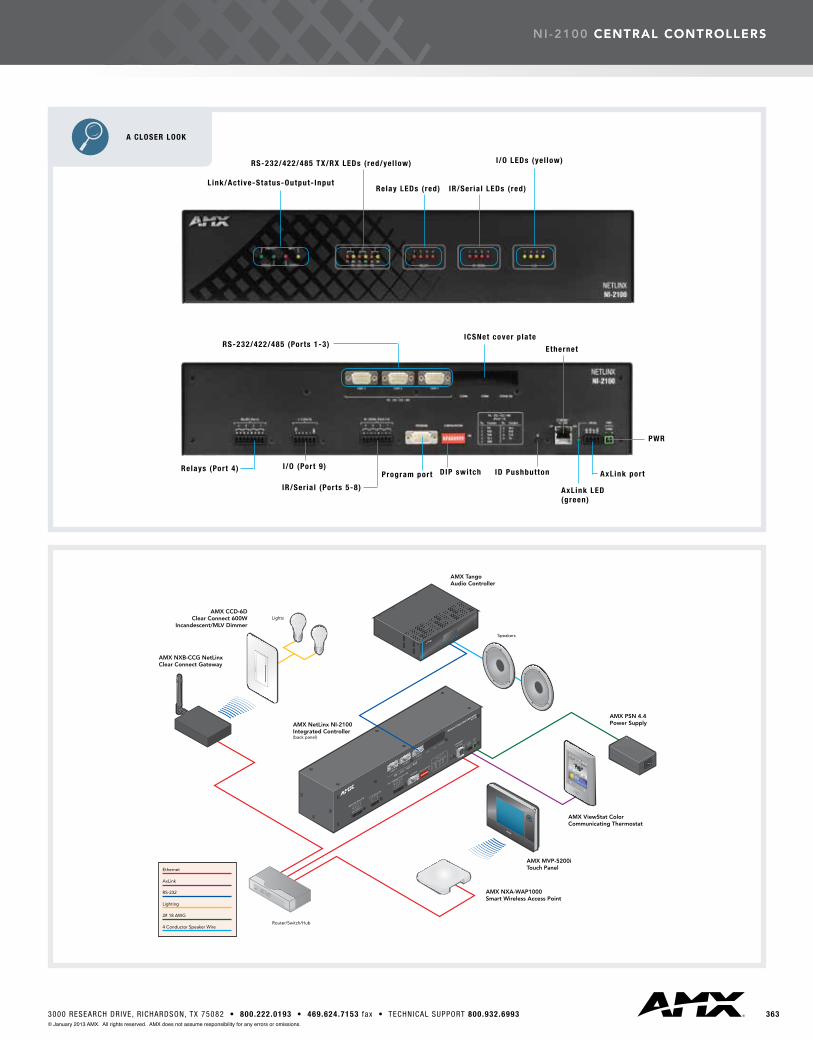
nI -2100 central controllers
A CLOSER LOOK
RS-232/422/485 (Ports 1-3)
L ink/Act ive-Status-Output- Input
RS-232/422/485 TX/RX LEDs ( red/yel low)
Relay LEDs ( red) IR/Ser ia l LEDs ( red)
I /O LEDs (ye l low)
Relays (Port 4) I /O (Port 9)
IR/Ser ia l (Ports 5-8)
Program port DIP switch
Ethernet
AxLink LED(green)
AxLink port
PWR
ICSNet cover p late
ID Pushbutton

364 US SALES AND SUPPORT 800.222.0193 • INTERNATIONAL SALES AND SUPPORT +1.469.624.7400 • www.amx.com© January 2013 AMX. All rights reserved. AMX does not assume responsibility for any errors or omissions.
RECOMMENDED ACCESSORIES DESCRIPTION PART # PAGE #
PSN6.5 6.5 Amp Power Supply (FG423-41) 415 PSN4.4 4.4 Amp Power Supply (FG423-45) 414NXA-ICSNET NetLinx ICSNet Communication Network Card (FG2105-10) 383NXA-CF2NI CompactFlash Upgrade (FG21116-xx) 382 CC-232 RS232/422 Cables (FG10-752-04) 420CC-NIRC IR Cables (FG10-000-11) 420
nI -2100 central controllers
SPECIFICATIONS
DIMENSIONS (HWD)
• 3 1/2” x 17” x 3 1/2” (8.8 cm x 43.2 cm x 8.8 cm)• RU: 2
WEIGHT
4.50 lbs (2.04 kg)
POWER
700 mA @ 12 VDC
ENCLOSURE
Metal with black matte finish
MEMORY
• 64 MB SDRAM• 1 MB of Non-volatile SRAM
COMPACT FLASH
2 GB Card or more (upgradeable)
ONBOARD MASTER
404 MIPS
CERTIFICATIONS
FCC Part 15 Class B, CE, and IEC 60950
FRONT PANEL COMPONENTS
• LINK/ACT: Green LED blinks when the Ethernet cables are connected and terminated correctly. Also blinks when receiving Ethernet data packets• Status: Green LED blinks to indicate that the system is programmed and communicating properly• Output: Red LED blinks when the Controller transmits data, sets channels and sends data strings, etc.• Input: Yellow LED blinks when the Controller receives data from button pushes, strings, commands, channel levels, etc.• RS-232/422/485 LEDs• Relay LEDs• IR/Serial LEDs• I/O LEDs• Rack-mount brackets: Provides an installation option for the Integrated Controller to be mounted into an equipment rack, when used with the Installation Kit (KA2105-01)
REAR PANEL CONNECTORS
• RS-232/422/485 (Ports 1 - 3)• ICSNet: Two RJ-45 connectors for ICSNet interface (provided by ICSNet daughter card)• ICSHub Out: RJ-45 connector provides data to a Hub connected to the Controller (provided by ICSNet daughter card)• Relay (Port 4)• Digital I/O (Port 9)• IR/Serial (Ports 5 - 8)• Program Port• Configuration DIP Switch: Sets the communication parameters for the Program port• ID Pushbutton• Ethernet Port: RJ-45 port for 10/100 Mbps communication. LEDs show communication activity, connection status, speeds, and mode information: - SPD (speed) - Yellow LED lights On when the connection speed is 100 Mbps and turns Off when the speed is 10 Mbps. - L/A (link/activity) - Green LED lights On when the Ethernet cables are connected and terminated correctly, and blinks when receiving Ethernet data packets.• AxLink LED: Green LED indicates the state of the AxLink port.• AxLink Port: 4-pin 3.5 mm mini-Phoenix (male) connector that provides data and power to external control devices• Power Port: 2-pin 3.5 mm mini-Phoenix (male) connector.
ENVIRONMENTAL
• Operating Temperature: 0° C (32° F) to 50° C (122° F)• Operating Humidity: 20% to 85% RH• Heat Dissipation (Typical): 28.7 BTU/hr
INCLUDED ACESSORIES
• 2-pin 3.5 mm mini-Phoenix (female) PWR connector (41-5025)• 4-pin 3.5 mm mini-Phoenix (female) AxLink connector (41-5047)• 6-pin 3.5 mm mini-Phoenix female I/O connector (41-5063)• 8-pin 3.5 mm mini-Phoenix female Relay connector (41-5083)• Two CC-NIRC IR Emitters• Two removable rack ears (62-2105-07)
central controllers
3653000 RESEARCH DRIVE, R ICHARDSON, TX 75082 • 800.222.0193 • 469.624.7153 fax • TECHNICAL SUPPORT 800.932.6993© January 2013 AMX. All rights reserved. AMX does not assume responsibility for any errors or omissions.
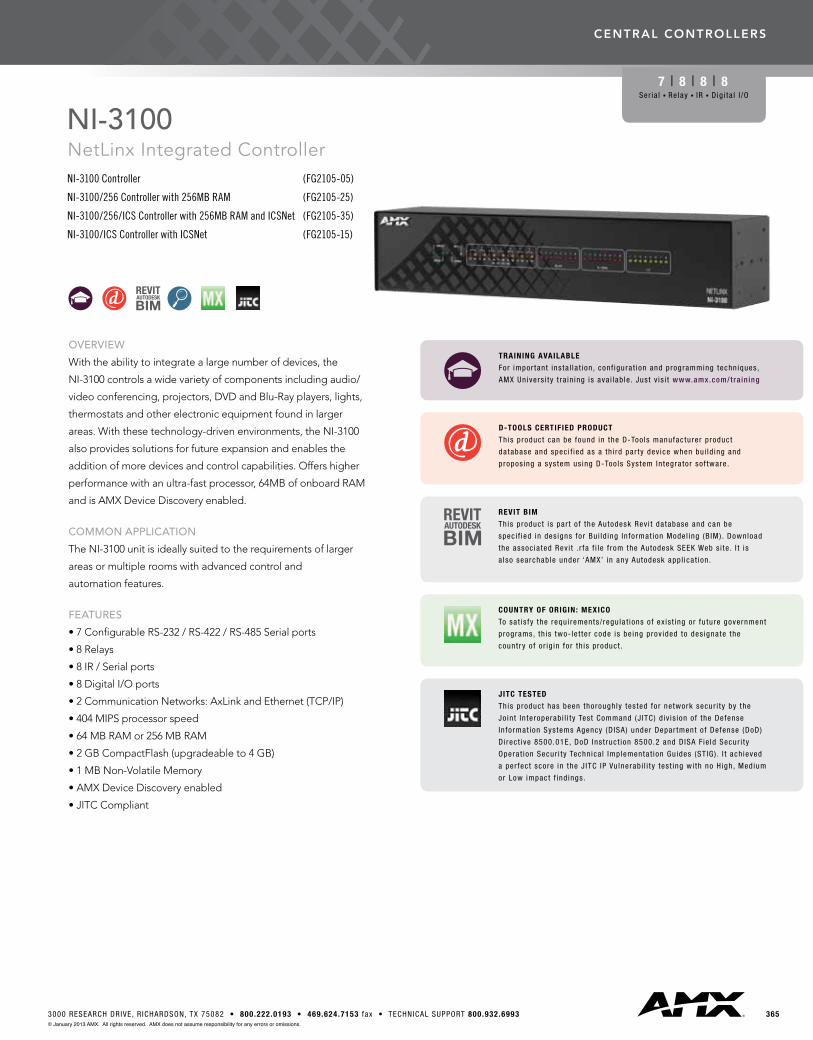
OVERVIEW
With the ability to integrate a large number of devices, the
NI-3100controlsawidevarietyofcomponentsincludingaudio/
videoconferencing,projectors,DVDandBlu-Rayplayers,lights,
thermostats and other electronic equipment found in larger
areas.Withthesetechnology-drivenenvironments,theNI-3100
also provides solutions for future expansion and enables the
additionofmoredevicesandcontrolcapabilities.Offershigher
performancewithanultra-fastprocessor,64MBofonboardRAM
andisAMXDeviceDiscoveryenabled.
COMMON APPLICATION
TheNI-3100unitisideallysuitedtotherequirementsoflarger
areas or multiple rooms with advanced control and
automation features.
FEATURES
•7ConfigurableRS-232/RS-422/RS-485Serialports
•8Relays
•8IR/Serialports
•8DigitalI/Oports
•2CommunicationNetworks:AxLinkandEthernet(TCP/IP)
•404MIPSprocessorspeed
•64MBRAMor256MBRAM
•2GBCompactFlash(upgradeableto4GB)
•1MBNon-VolatileMemory
•AMXDeviceDiscoveryenabled
•JITCCompliant
NI-3100NetLinx Integrated Controller NI-3100 Controller (FG2105-05)
NI-3100/256 Controller with 256MB RAM (FG2105-25)
NI-3100/256/ICS Controller with 256MB RAM and ICSNet (FG2105-35)
NI-3100/ICS Controller with ICSNet (FG2105-15)
7 | 8 | 8 | 8Ser ia l n Re lay n IR n Dig i ta l I /O
D-TOOLS CERTIFIED PRODUCT
This product can be found in the D-Too ls manufacturer product
da tabase and spec i f ied as a th i rd par ty dev ice when bu i ld ing and
propos ing a sys tem us ing D-Too ls Sys tem In tegra tor so f tware .
COUNTRY OF ORIGIN: MEXICO
To sa t is fy the requ i rements / regu la t ions o f ex is t ing or fu ture government
programs, th is two- le t te r code is be ing prov ided to des igna te the
count r y o f o r ig in fo r th is product .
TRAINING AVAILABLE
For impor tant ins ta l la t ion , conf igura t ion and programming techn iques ,
AMX Un ivers i ty t ra in ing is ava i lab le . Jus t v is i t www.amx.com/tra in ing
REVIT BIM
This product i s par t o f the Autodesk Rev i t da tabase and can be
spec i f ied in des igns fo r Bu i ld ing In format ion Mode l ing (B IM) . Download
the assoc ia ted Rev i t . r fa f i l e f rom the Autodesk SEEK Web s i te . I t i s
a lso searchab le under ‘AMX’ in any Autodesk app l ica t ion .
JITC TESTED
This product has been thorough ly tes ted fo r network secur i ty by the
Jo in t In teroperab i l i t y Test Command (J ITC) d iv is ion o f the Defense
In format ion Systems Agency (D ISA) under Depar tment o f Defense (DoD)
D i rec t ive 8500.01E, DoD Ins t ruc t ion 8500.2 and D ISA Fie ld Secur i ty
Opera t ion Secur i ty Techn ica l Implementa t ion Gu ides (ST IG) . I t ach ieved
a per fec t score in the J ITC IP Vu lnerab i l i t y tes t ing wi th no H igh, Medium
or Low impact f ind ings .
366 US SALES AND SUPPORT 800.222.0193 • INTERNATIONAL SALES AND SUPPORT +1.469.624.7400 • www.amx.com© January 2013 AMX. All rights reserved. AMX does not assume responsibility for any errors or omissions.
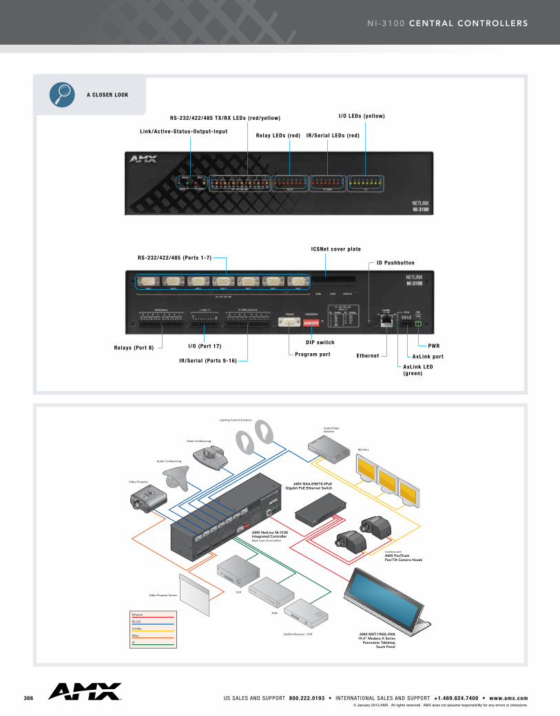
nI -3100 central controllers
A CLOSER LOOK
RS-232/422/485 (Ports 1-7)
Relays (Port 8) I /O (Port 17)
IR/Ser ia l (Ports 9-16)Program port
DIP switch
Ethernet
AxLink LED(green)
AxLink port
PWR
ICSNet cover p late
ID Pushbutton
Link/Act ive-Status-Output- Input
RS-232/422/485 TX/RX LEDs ( red/yel low)
Relay LEDs ( red) IR/Ser ia l LEDs ( red)
I /O LEDs (ye l low)
3673000 RESEARCH DRIVE, R ICHARDSON, TX 75082 • 800.222.0193 • 469.624.7153 fax • TECHNICAL SUPPORT 800.932.6993© January 2013 AMX. All rights reserved. AMX does not assume responsibility for any errors or omissions.
RECOMMENDED ACCESSORIES DESCRIPTION PART # PAGE #
PSN6.5 6.5 Amp Power Supply (FG423-41) 415 PSN4.4 4.4 Amp Power Supply (FG423-45) 414NXA-ICSNET NetLinx ICSNet Communication Network Card (FG2105-10) 383NXA-CF2NI CompactFlash Upgrade (FG21116-xx) 382 CC-232 RS232/422 Cables (FG10-752-04) 420CC-NIRC IR Cables (FG10-000-11) 420
nI -3100 central controllers
SPECIFICATIONS
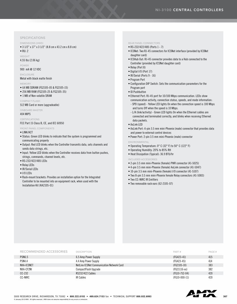
DIMENSIONS (HWD)
• 3 1/2” x 17” x 3 1/2” (8.8 cm x 43.2 cm x 8.8 cm)• RU: 2
WEIGHT
4.55 lbs (2.06 kg)
POWER
900 mA @ 12 VDC
ENCLOSURE
Metal with black matte finish
MEMORY
• 64 MB SDRAM (FG2105-05 & FG2105-15)• 256 MB RAM (FG2105-25 & FG2105-35)• 1 MB of Non-volatile SRAM
COMPACT FLASH
512 MB Card or more (upgradeable)
ONBOARD MASTER
404 MIPS
CERTIFICATIONS
FCC Part 15 Class B, CE, and IEC 60950
FRONT PANEL COMPONENTS
• LINK/ACT• Status: Green LED blinks to indicate that the system is programmed and communicating properly• Output: Red LED blinks when the Controller transmits data, sets channels and sends data strings, etc.• Input: Yellow LED blinks when the Controller receives data from button pushes, strings, commands, channel levels, etc.• RS-232/422/485 LEDs• Relay LEDs• IR/Serial LEDs• I/O LEDs• Rack-mount brackets: Provides an installation option for the Integrated Controller to be mounted into an equipment rack, when used with the Installation Kit (KA2105-01)
REAR PANEL CONNECTORS
• RS-232/422/485 (Ports 1 - 7)• ICSNet: Two RJ-45 connectors for ICSNet interface (provided by ICSNet daughter card)• ICSHub Out: RJ-45 connector provides data to a Hub connected to the Controller (provided by ICSNet daughter card)• Relay (Port 8)• Digital I/O (Port 17)• IR/Serial (Ports 9 - 16)• Program Port• Configuration DIP Switch: Sets the communication parameters for the Program port• ID Pushbutton• Ethernet Port: RJ-45 port for 10/100 Mbps communication. LEDs show communication activity, connection status, speeds, and mode information: - SPD (speed) - Yellow LED lights On when the connection speed is 100 Mbps and turns Off when the speed is 10 Mbps. - L/A (link/activity) - Green LED lights On when the Ethernet cables are connected and terminated correctly, and blinks when receiving Ethernet data packets.• AxLink LED• AxLink Port: 4-pin 3.5 mm mini-Phoenix (male) connector that provides data and power to external control devices• Power Port: 2-pin 3.5 mm mini-Phoenix (male) connector
ENVIRONMENTAL
• Operating Temperature: 0° C (32° F) to 50° C (122° F)• Operating Humidity: 20% to 85% RH• Heat Dissipation (Typical): 36.9 BTU/hr
INCLUDED ACCESSORIES
• 2-pin 3.5 mm mini-Phoenix (female) PWR connector (41-5025)• 4-pin 3.5 mm mini-Phoenix (female) AxLink connector (41-5047)• 10-pin 3.5 mm mini-Phoenix (female) I/O connector (41-5107)• Two 8-pin 3.5 mm mini-Phoenix female Relay connectors (41-5083)• Two CC-NIRC IR Emitters• Two removable rack ears (62-2105-07)

central controllers
368 US SALES AND SUPPORT 800.222.0193 • INTERNATIONAL SALES AND SUPPORT +1.469.624.7400 • www.amx.com© January 2013 AMX. All rights reserved. AMX does not assume responsibility for any errors or omissions.
RECOMMENDED ACCESSORIES DESCRIPTION PART # PAGE #
PSN6.5 6.5 Amp Power Supply (FG423-41) 415 PSN4.4 4.4 Amp Power Supply (FG423-45) 414CC-232 RS232/422 Cables (FG10-752-04) 420CC-NIRC IR Cables (FG10-000-11) 420CC-NET Cat5 Ethernet Cable (FG10-051-10) 418CC-USB-NI USB Programming Cable (FG10-2105) 418
OVERVIEW
Withitsgloss-blackface,bluepowerbarandblueandwhite
statusLEDs,theNI-3101-SIGcanbeplacedonopenracks,open
shelves,tables,hometheatersorbehindthescenesinarack.
Measuringjust1rackunit(RU:1)high,theNI-3101-SIGfreesup
spaceforothercomponentswhiletheextendedrackdepth(10”)
simplifies rear connections.
Withextremelyfast32-bitprocessingand64MBofonboardRAM,
theNI-3101-SIGiscapableofprocessingthousandsofcontrol
and automation commands per second. Whether your control
requirementsaresimpleorsophisticated,theNI-3101-SIGisfast,
accurateandimmediate.Inaddition,itfeaturesaconvenientUSB
programming port to simplify configuration.
COMMON APPLICATION
TheNI-3101-SIGisidealforcontrollingdevicesinlargeareasand
multiplerooms.Itssleekstylingandprofessionalshowroomfinish
allow it to be displayed prominently in home theater
environmentsorworkequallywellbehindthescenesinarack.
FEATURES
•6ConfigurableRS-232/RS-422/RS-485SerialPorts
•8Relays
•8IR/Serialports
•8DigitalI/Oports
•2CommunicationNetworks:AxLinkand10/100Ethernet
(TCP/IP)
•IntegratedUSBprogrammingport
•404MIPSprocessorspeed
•64MBRAM
•256MBFlashMemory
•1MBNon-VolatileMemory
•AMXDeviceDiscoveryenabled
•JITCCompliant
NI-3101-SIGSignature Series NetLinx® Integrated Controller(FG2105-08)
6 | 8 | 8 | 8Ser ia l n Re lay n IR n D ig i ta l I /O
WATCH THE VIDEO
See the N I-3101-S IG in ac t ion by wa tch ing the v ideo pro f i le on l ine
a t : www.amx.com/assets/v ideos/NI-3101-SIG.mp4
D-TOOLS CERTIFIED PRODUCT
This product can be found in the D-Too ls manufacturer product
da tabase and spec i f ied as a th i rd par ty dev ice when bu i ld ing and
propos ing a sys tem us ing D-Too ls Sys tem In tegra tor so f tware .
COUNTRY OF ORIGIN: MEXICO
To sa t is fy the requ i rements / regu la t ions o f ex is t ing or fu ture government
programs, th is two- le t te r code is be ing prov ided to des igna te the
count r y o f o r ig in fo r th is product .
TRAINING AVAILABLE
For impor tant ins ta l la t ion , conf igura t ion and programming techn iques ,
AMX Un ivers i ty t ra in ing is ava i lab le . Jus t v is i t www.amx.com/tra in ing

3693000 RESEARCH DRIVE, R ICHARDSON, TX 75082 • 800.222.0193 • 469.624.7153 fax • TECHNICAL SUPPORT 800.932.6993© January 2013 AMX. All rights reserved. AMX does not assume responsibility for any errors or omissions.
A CLOSER LOOK
Power
RS-232/422/485 (Ports 1-6) I /O (Port 17)Conf igurat ion
Switches ID SwitchAxLink
LEDPower12 VDC
RS-232/422/485 TX/RX LEDs
Relays (Port 8) IR/Ser ia l (Ports 9-16) ProgrammingPort
Ethernet10/100 Port
AxLinkPort
IR/Ser ia l LEDs
Link/Act ive-Status- I /O Relay LEDs I/O LEDs
nI -3101-s IG central controllers
370 US SALES AND SUPPORT 800.222.0193 • INTERNATIONAL SALES AND SUPPORT +1.469.624.7400 • www.amx.com© January 2013 AMX. All rights reserved. AMX does not assume responsibility for any errors or omissions.
nI -3101-s IG central controllers
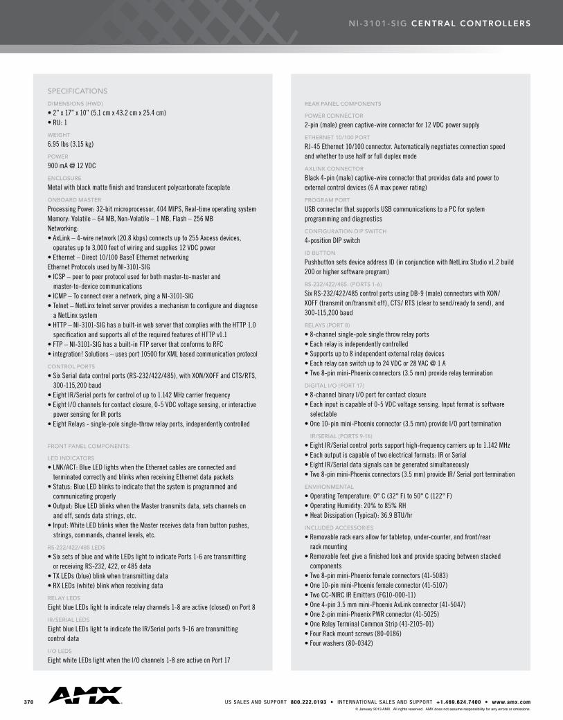
SPECIFICATIONS
DIMENSIONS (HWD)
• 2” x 17” x 10” (5.1 cm x 43.2 cm x 25.4 cm) • RU: 1
WEIGHT
6.95 lbs (3.15 kg)
POWER
900 mA @ 12 VDC
ENCLOSURE
Metal with black matte finish and translucent polycarbonate faceplate
ONBOARD MASTER
Processing Power: 32-bit microprocessor, 404 MIPS, Real-time operating systemMemory: Volatile – 64 MB, Non-Volatile – 1 MB, Flash – 256 MBNetworking:• AxLink – 4-wire network (20.8 kbps) connects up to 255 Axcess devices, operates up to 3,000 feet of wiring and supplies 12 VDC power• Ethernet – Direct 10/100 BaseT Ethernet networkingEthernet Protocols used by NI-3101-SIG• ICSP – peer to peer protocol used for both master-to-master and master-to-device communications• ICMP – To connect over a network, ping a NI-3101-SIG• Telnet – NetLinx telnet server provides a mechanism to configure and diagnose a NetLinx system• HTTP – NI-3101-SIG has a built-in web server that complies with the HTTP 1.0 specification and supports all of the required features of HTTP v1.1• FTP – NI-3101-SIG has a built-in FTP server that conforms to RFC• integration! Solutions – uses port 10500 for XML based communication protocol
CONTROL PORTS
• Six Serial data control ports (RS-232/422/485), with XON/XOFF and CTS/RTS, 300-115,200 baud• Eight IR/Serial ports for control of up to 1.142 MHz carrier frequency• Eight I/O channels for contact closure, 0-5 VDC voltage sensing, or interactive power sensing for IR ports• Eight Relays - single-pole single-throw relay ports, independently controlled
FRONT PANEL COMPONENTS:
LED INDICATORS
• LNK/ACT: Blue LED lights when the Ethernet cables are connected and terminated correctly and blinks when receiving Ethernet data packets• Status: Blue LED blinks to indicate that the system is programmed and communicating properly• Output: Blue LED blinks when the Master transmits data, sets channels on and off, sends data strings, etc.• Input: White LED blinks when the Master receives data from button pushes, strings, commands, channel levels, etc.
RS-232/422/485 LEDS
• Six sets of blue and white LEDs light to indicate Ports 1-6 are transmitting or receiving RS-232, 422, or 485 data• TX LEDs (blue) blink when transmitting data• RX LEDs (white) blink when receiving data
RELAY LEDS
Eight blue LEDs light to indicate relay channels 1-8 are active (closed) on Port 8
IR/SERIAL LEDS
Eight blue LEDs light to indicate the IR/Serial ports 9-16 are transmitting control data
I/O LEDS
Eight white LEDs light when the I/O channels 1-8 are active on Port 17
REAR PANEL COMPONENTS
POWER CONNECTOR
2-pin (male) green captive-wire connector for 12 VDC power supply
ETHERNET 10/100 PORT
RJ-45 Ethernet 10/100 connector. Automatically negotiates connection speed and whether to use half or full duplex mode
AXLINK CONNECTOR
Black 4-pin (male) captive-wire connector that provides data and power to external control devices (6 A max power rating)
PROGRAM PORT
USB connector that supports USB communications to a PC for system programming and diagnostics
CONFIGURATION DIP SWITCH
4-position DIP switch
ID BUTTON
Pushbutton sets device address ID (in conjunction with NetLinx Studio v1.2 build 200 or higher software program)
RS-232/422/485: (PORTS 1-6)
Six RS-232/422/485 control ports using DB-9 (male) connectors with XON/XOFF (transmit on/transmit off), CTS/ RTS (clear to send/ready to send), and 300-115,200 baud
RELAYS (PORT 8)
• 8-channel single-pole single throw relay ports• Each relay is independently controlled• Supports up to 8 independent external relay devices• Each relay can switch up to 24 VDC or 28 VAC @ 1 A• Two 8-pin mini-Phoenix connectors (3.5 mm) provide relay termination
DIGITAL I/O (PORT 17)
• 8-channel binary I/O port for contact closure• Each input is capable of 0-5 VDC voltage sensing. Input format is software selectable• One 10-pin mini-Phoenix connector (3.5 mm) provide I/O port termination
IR/SERIAL (PORTS 9-16)
• Eight IR/Serial control ports support high-frequency carriers up to 1.142 MHz• Each output is capable of two electrical formats: IR or Serial• Eight IR/Serial data signals can be generated simultaneously• Two 8-pin mini-Phoenix connectors (3.5 mm) provide IR/ Serial port termination
ENVIRONMENTAL
• Operating Temperature: O° C (32° F) to 50° C (122° F)• Operating Humidity: 20% to 85% RH• Heat Dissipation (Typical): 36.9 BTU/hr
INCLUDED ACCESSORIES
• Removable rack ears allow for tabletop, under-counter, and front/rear rack mounting• Removable feet give a finished look and provide spacing between stacked components• Two 8-pin mini-Phoenix female connectors (41-5083)• One 10-pin mini-Phoenix female connector (41-5107)• Two CC-NIRC IR Emitters (FG10-000-11)• One 4-pin 3.5 mm mini-Phoenix AxLink connector (41-5047)• One 2-pin mini-Phoenix PWR connector (41-5025)• One Relay Terminal Common Strip (41-2105-01)• Four Rack mount screws (80-0186)• Four washers (80-0342)

central controllers
3713000 RESEARCH DRIVE, R ICHARDSON, TX 75082 • 800.222.0193 • 469.624.7153 fax • TECHNICAL SUPPORT 800.932.6993© January 2013 AMX. All rights reserved. AMX does not assume responsibility for any errors or omissions.
OVERVIEW
TheNI-4100providesversatilitywiththeabilitytointegrate
the largest number of devices in the NI Series of Master
Controllers,includingprojectors,lighting,DVDandBlu-Ray
players, thermostats and other electronic equipment. In these
technology-driven environments, this solution allows for the
future addition of more devices and control capabilities. With a
perfectmixofcompatibleformats,theNI-4100offersflexibility
andcustomizationforbusinessesexperiencingrapidgrowthand
for homes that demand seamless integration of technology and
design.TheNI-4100provideshigherperformancewithafaster
processor,64MBofonboardRAMandDuet-compatibility.
COMMON APPLICATION
TheNI-4100isgearedtomeetthehigh-endcontroland
automation requirements of the most sophisticated and complex
commercial and residential installations.
FEATURES
•7ConfigurableRS-232/RS-422/RS-485Serialports
•8Relays
•8IR/Serialports
•8DigitalI/Oports
•3CommunicationNetworks:AxLink,ICSNetand
Ethernet(TCP/IP)
•4NetLinxControlCardExpansionslotsthatsupportallNXC
control cards
•404MIPSprocessorspeed
•64MBRAMor256MBRAM
•2GBCompactFlash(upgradeableto4GB)
•1MBNon-VolatileMemory
•AMXDeviceDiscoveryenabled
•JITCCompliant
NI-4100NetLinx Integrated Controller NI-4100 Controller (FG2105-06)
NI-4100/256 Controller with 256MB RAM (FG2105-26)
7 | 8 | 8 | 8Ser ia l n Re lay n IR n Dig i ta l I /O
D-TOOLS CERTIFIED PRODUCT
This product can be found in the D-Too ls manufacturer product
da tabase and spec i f ied as a th i rd par ty dev ice when bu i ld ing and
propos ing a sys tem us ing D-Too ls Sys tem In tegra tor so f tware .
COUNTRY OF ORIGIN: MEXICO
To sa t is fy the requ i rements / regu la t ions o f ex is t ing or fu ture government
programs, th is two- le t te r code is be ing prov ided to des igna te the
count r y o f o r ig in fo r th is product .
TRAINING AVAILABLE
For impor tant ins ta l la t ion , conf igura t ion and programming techn iques ,
AMX Un ivers i ty t ra in ing is ava i lab le . Jus t v is i t www.amx.com/tra in ing
REVIT BIM
This product i s par t o f the Autodesk Rev i t da tabase and can be
spec i f ied in des igns fo r Bu i ld ing In format ion Mode l ing (B IM) . Download
the assoc ia ted Rev i t . r fa f i l e f rom the Autodesk SEEK Web s i te . I t i s
a lso searchab le under ‘AMX’ in any Autodesk app l ica t ion .
JITC TESTED
This product has been thorough ly tes ted fo r network secur i ty by the
Jo in t In teroperab i l i t y Test Command (J ITC) d iv is ion o f the Defense
In format ion Systems Agency (D ISA) under Depar tment o f Defense (DoD)
D i rec t ive 8500.01E, DoD Ins t ruc t ion 8500.2 and D ISA Fie ld Secur i ty
Opera t ion Secur i ty Techn ica l Implementa t ion Gu ides (ST IG) . I t ach ieved
a per fec t score in the J ITC IP Vu lnerab i l i t y tes t ing wi th no H igh, Medium
or Low impact f ind ings .

372 US SALES AND SUPPORT 800.222.0193 • INTERNATIONAL SALES AND SUPPORT +1.469.624.7400 • www.amx.com© January 2013 AMX. All rights reserved. AMX does not assume responsibility for any errors or omissions.
nI -4100 central controllers
A CLOSER LOOK
RS-232/422/485 (Ports 1-7)
Relays (Port 8)
CardFrame DIP switch
I/O (Port 17)
Slot 1-4 connectors IR/Ser ia l (Ports 9-16)Program port
DIP switchEthernet
AxLink LED(green)
AxLink port
PWR
ICSNet (2)
ICSHub Out
L ink/Act ive-Status-Output- Input
NetL inx Card Slots (1-4)
RS-232/422/485 TX/RX LEDs ( red/yel low)
RelayLEDs ( red)
IR/Ser ia l LEDs ( red)
I /O LEDs (ye l low)

3733000 RESEARCH DRIVE, R ICHARDSON, TX 75082 • 800.222.0193 • 469.624.7153 fax • TECHNICAL SUPPORT 800.932.6993© January 2013 AMX. All rights reserved. AMX does not assume responsibility for any errors or omissions.
RECOMMENDED ACCESSORIES DESCRIPTION PART # PAGE #
PSN6.5 6.5 Amp Power Supply (FG423-41) 415 PSN4.4 4.4 Amp Power Supply (FG423-45) 414NXA-CF2NI CompactFlash Upgrade for NI Series Controllers (FG21116-xx) 382
SPECIFICATIONS
DIMENSIONS (HWD)
• 5 3/16” x 17” x 9 5/16” (13.2 cm x 43.2 cm x 23.7 cm)• RU: 3
WEIGHT
9.15 lbs (4.15 kg)
POWER
900 mA @ 12 VDC
ENCLOSURE
Metal with black matte finish
MEMORY
• 64 MB SDRAM (FG2105-06)• 256 MB RAM (FG2105-26)• 1 MB of Non-volatile SRAM
COMPACT FLASH
2 GB Compact Flash (upgradeable to 4 GB factory programmed)
ONBOARD MASTER
404 MIPS
CERTIFICATIONS
FCC Part 15 Class B, CE, and IEC 60950
FRONT PANEL COMPONENTS
• LINK/ACT: Green LED blinks when the Ethernet cables are connected and terminated correctly. Also blinks when receiving Ethernet data packets• Status: Green LED blinks to indicate that the system is programmed and communicating properly• Output: Red LED blinks when the Controller transmits data, sets channels, sends data strings, etc.• Input: Yellow LED blinks when the Controller receives data from button pushes, strings, commands, channel levels, etc.• RS-232/422/485 LEDs• Relay LEDs• IR/Serial LED• I/O LEDs• NetLinx Control Card Slot 1 - 4• Rack-mount brackets: Provides an installation option for the Integrated Controller to be mounted into an equipment rack, when used with the Installation Kit (KA2105-01)
REAR PANEL CONNECTORS
• RS-232/422/485 (Ports 1 - 7)• ICSNet: Two RJ-45 connectors for ICSNet interface (included)• ICSHub Out: RJ-45 connector provides data to a Hub connected to the Controller (included)• Relay (Port 8)• Digital I/O (Port 17)• IR/Serial (Ports 9 - 16)• Program Port• Configuration DIP Switch: Sets the communication parameters for the Program port• ID Pushbutton: Sets the NetLinx ID (Device only) assignment for the device• Ethernet Port: RJ-45 port for 10/100 Mbps communication. LEDs show communication activity, connection status, speeds, and mode information: - SPD (speed) - Yellow LED lights On when the connection speed is 100 Mbps and turns Off when the speed is 10 Mbps. - L/A (link/activity) - Green LED lights On when the Ethernet cables are connected and terminated correctly, and blinks when receiving Ethernet data packets.• AxLink LED: Green LED indicates the state of the AxLink port• AxLink Port: 4-pin 3.5 mm mini-Phoenix (male) connector that provides data and power to external control devices• Power Port: 2-pin 3.5 mm mini-Phoenix (male) connector• CardFrame Number DIP Switch
ENVIRONMENTAL
• Operating Temperature: O° C (32° F) to 50° C (122° F)• Operating Humidity: 20% to 85% RH• Heat Dissipation (Typical): 36.9 BTU/hr
INCLUDED ACCESSORIES
• 2-pin 3.5 mm mini-Phoenix (female) PWR connector (41-5025)• 4-pin 3.5 mm mini-Phoenix (female) AxLink connector (41-5047)• 10-pin 3.5 mm mini-Phoenix (female) I/O connector (41-5107)• Two 8-pin 3.5 mm mini-Phoenix (female) Relay connectors (41-5083)• Two CC-NIRC IR Emitters • Two removable rack ears (62-2105-07)
nI -4100 central controllers
central controllers
374 US SALES AND SUPPORT 800.222.0193 • INTERNATIONAL SALES AND SUPPORT +1.469.624.7400 • www.amx.com© January 2013 AMX. All rights reserved. AMX does not assume responsibility for any errors or omissions.
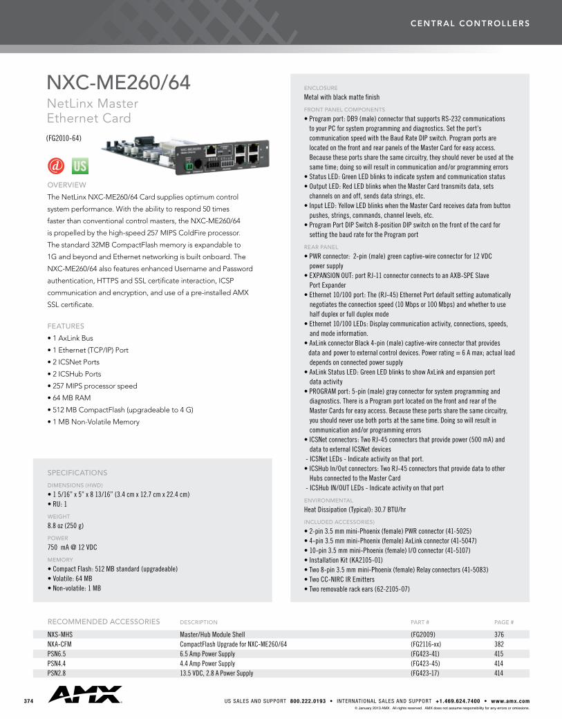
OVERVIEW
TheNetLinxNXC-ME260/64Cardsuppliesoptimumcontrol
systemperformance.Withtheabilitytorespond50times
fasterthanconventionalcontrolmasters,theNXC-ME260/64
ispropelledbythehigh-speed257MIPSColdFireprocessor.
Thestandard32MBCompactFlashmemoryisexpandableto
1GandbeyondandEthernetnetworkingisbuiltonboard.The
NXC-ME260/64alsofeaturesenhancedUsernameandPassword
authentication, HTTPS and SSL certificate interaction, ICSP
communication and encryption, and use of a pre-installed AMX
SSL certificate.
FEATURES
•1AxLinkBus
•1Ethernet(TCP/IP)Port
•2ICSNetPorts
•2ICSHubPorts
•257MIPSprocessorspeed
•64MBRAM
•512MBCompactFlash(upgradeableto4G)
•1MBNon-VolatileMemory
NXC-ME260/64NetLinx Master Ethernet Card(FG2010-64)
ENCLOSURE
Metal with black matte finish
FRONT PANEL COMPONENTS
• Program port: DB9 (male) connector that supports RS-232 communications to your PC for system programming and diagnostics. Set the port’s communication speed with the Baud Rate DIP switch. Program ports are located on the front and rear panels of the Master Card for easy access. Because these ports share the same circuitry, they should never be used at the same time; doing so will result in communication and/or programming errors
• Status LED: Green LED blinks to indicate system and communication status• Output LED: Red LED blinks when the Master Card transmits data, sets
channels on and off, sends data strings, etc.• Input LED: Yellow LED blinks when the Master Card receives data from button
pushes, strings, commands, channel levels, etc.• Program Port DIP Switch 8-position DIP switch on the front of the card for
setting the baud rate for the Program port
REAR PANEL
• PWR connector: 2-pin (male) green captive-wire connector for 12 VDC power supply
• EXPANSION OUT: port RJ-11 connector connects to an AXB-SPE Slave Port Expander• Ethernet 10/100 port: The (RJ-45) Ethernet Port default setting automatically negotiates the connection speed (10 Mbps or 100 Mbps) and whether to use half duplex or full duplex mode• Ethernet 10/100 LEDs: Display communication activity, connections, speeds, and mode information.• AxLink connector Black 4-pin (male) captive-wire connector that provides data and power to external control devices. Power rating = 6 A max; actual load depends on connected power supply• AxLink Status LED: Green LED blinks to show AxLink and expansion port data activity• PROGRAM port: 5-pin (male) gray connector for system programming and diagnostics. There is a Program port located on the front and rear of the Master Cards for easy access. Because these ports share the same circuitry, you should never use both ports at the same time. Doing so will result in communication and/or programming errors• ICSNet connectors: Two RJ-45 connectors that provide power (500 mA) and data to external ICSNet devices - ICSNet LEDs - Indicate activity on that port.• ICSHub In/Out connectors: Two RJ-45 connectors that provide data to other Hubs connected to the Master Card - ICSHub IN/OUT LEDs - Indicate activity on that port
ENVIRONMENTAL
Heat Dissipation (Typical): 30.7 BTU/hr
INCLUDED ACCESSORIES)
• 2-pin 3.5 mm mini-Phoenix (female) PWR connector (41-5025)• 4-pin 3.5 mm mini-Phoenix (female) AxLink connector (41-5047)• 10-pin 3.5 mm mini-Phoenix (female) I/O connector (41-5107)• Installation Kit (KA2105-01)• Two 8-pin 3.5 mm mini-Phoenix (female) Relay connectors (41-5083)• Two CC-NIRC IR Emitters• Two removable rack ears (62-2105-07)
SPECIFICATIONS
DIMENSIONS (HWD)
• 1 5/16” x 5” x 8 13/16” (3.4 cm x 12.7 cm x 22.4 cm)• RU: 1
WEIGHT
8.8 oz (250 g)
POWER
750 mA @ 12 VDC
MEMORY
• Compact Flash: 512 MB standard (upgradeable)• Volatile: 64 MB• Non-volatile: 1 MB
RECOMMENDED ACCESSORIES DESCRIPTION PART # PAGE #
NXS-MHS Master/Hub Module Shell (FG2009) 376NXA-CFM CompactFlash Upgrade for NXC-ME260/64 (FG2116-xx) 382 PSN6.5 6.5 Amp Power Supply (FG423-41) 415 PSN4.4 4.4 Amp Power Supply (FG423-45) 414PSN2.8 13.5 VDC, 2.8 A Power Supply (FG423-17) 414
central controllers
3753000 RESEARCH DRIVE, R ICHARDSON, TX 75082 • 800.222.0193 • 469.624.7153 fax • TECHNICAL SUPPORT 800.932.6993© January 2013 AMX. All rights reserved. AMX does not assume responsibility for any errors or omissions.
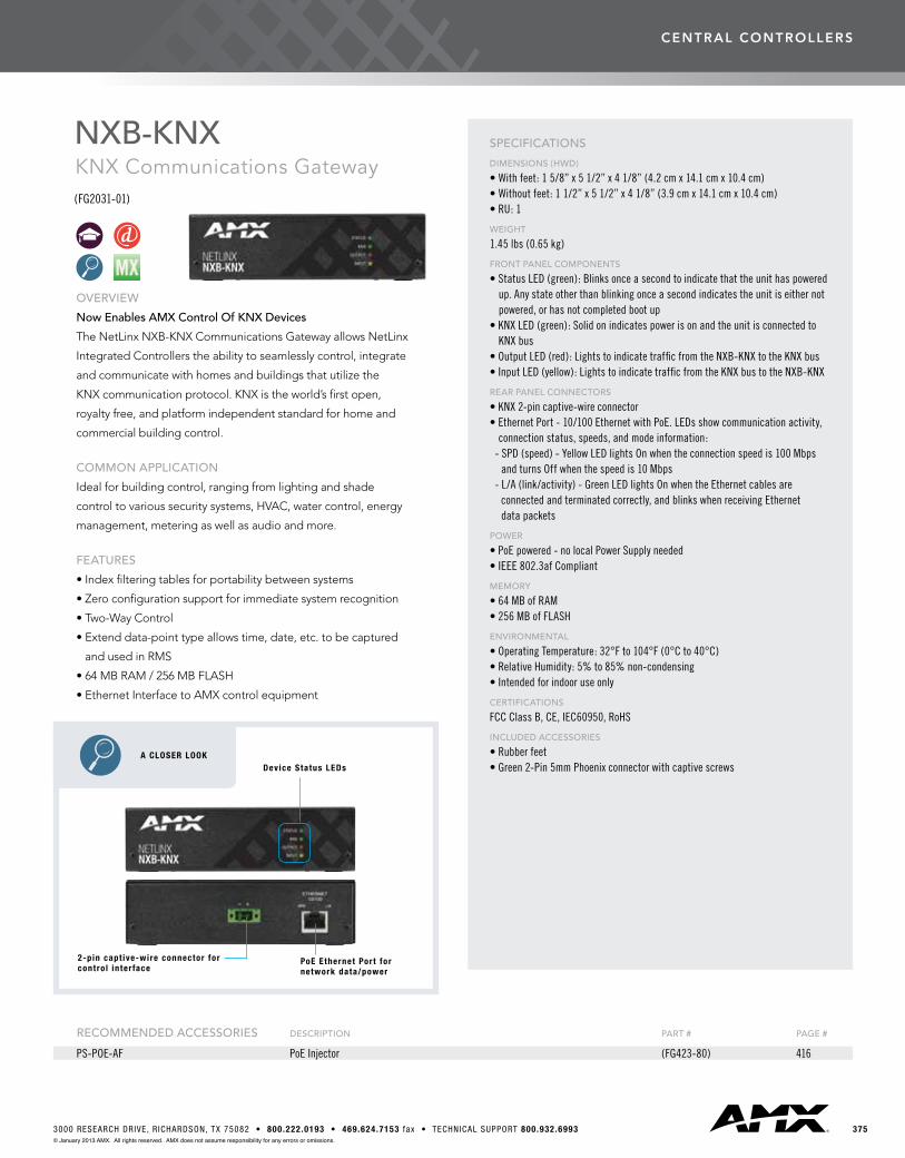
OVERVIEW
Now Enables AMX Control Of KNX Devices
TheNetLinxNXB-KNXCommunicationsGatewayallowsNetLinx
Integrated Controllers the ability to seamlessly control, integrate
andcommunicatewithhomesandbuildingsthatutilizethe
KNXcommunicationprotocol.KNXistheworld’sfirstopen,
royalty free, and platform independent standard for home and
commercial building control.
COMMON APPLICATION
Ideal for building control, ranging from lighting and shade
controltovarioussecuritysystems,HVAC,watercontrol,energy
management, metering as well as audio and more.
FEATURES
•Indexfilteringtablesforportabilitybetweensystems
•Zeroconfigurationsupportforimmediatesystemrecognition
•Two-WayControl
•Extenddata-pointtypeallowstime,date,etc.tobecaptured
and used in RMS
•64MBRAM/256MBFLASH
•EthernetInterfacetoAMXcontrolequipment
NXB-KNXKNX Communications Gateway(FG2031-01)
SPECIFICATIONS
DIMENSIONS (HWD)
• With feet: 1 5/8” x 5 1/2” x 4 1/8” (4.2 cm x 14.1 cm x 10.4 cm)• Without feet: 1 1/2” x 5 1/2” x 4 1/8” (3.9 cm x 14.1 cm x 10.4 cm)• RU: 1
WEIGHT
1.45 lbs (0.65 kg)
FRONT PANEL COMPONENTS
• Status LED (green): Blinks once a second to indicate that the unit has powered up. Any state other than blinking once a second indicates the unit is either not powered, or has not completed boot up• KNX LED (green): Solid on indicates power is on and the unit is connected to KNX bus• Output LED (red): Lights to indicate traffic from the NXB-KNX to the KNX bus• Input LED (yellow): Lights to indicate traffic from the KNX bus to the NXB-KNX
REAR PANEL CONNECTORS
• KNX 2-pin captive-wire connector• Ethernet Port - 10/100 Ethernet with PoE. LEDs show communication activity, connection status, speeds, and mode information: - SPD (speed) - Yellow LED lights On when the connection speed is 100 Mbps and turns Off when the speed is 10 Mbps - L/A (link/activity) - Green LED lights On when the Ethernet cables are connected and terminated correctly, and blinks when receiving Ethernet data packets
POWER
• PoE powered - no local Power Supply needed• IEEE 802.3af Compliant
MEMORY
• 64 MB of RAM• 256 MB of FLASH
ENVIRONMENTAL
• Operating Temperature: 32°F to 104°F (0°C to 40°C)• Relative Humidity: 5% to 85% non-condensing• Intended for indoor use only
CERTIFICATIONS
FCC Class B, CE, IEC60950, RoHS
INCLUDED ACCESSORIES
• Rubber feet• Green 2-Pin 5mm Phoenix connector with captive screws
RECOMMENDED ACCESSORIES DESCRIPTION PART # PAGE #
PS-POE-AF PoE Injector (FG423-80) 416
A CLOSER LOOK Device Status LEDs
2-pin capt ive-wire connector for contro l inter face
PoE Ethernet Port for network data/power
central controllers
376 US SALES AND SUPPORT 800.222.0193 • INTERNATIONAL SALES AND SUPPORT +1.469.624.7400 • www.amx.com© January 2013 AMX. All rights reserved. AMX does not assume responsibility for any errors or omissions.
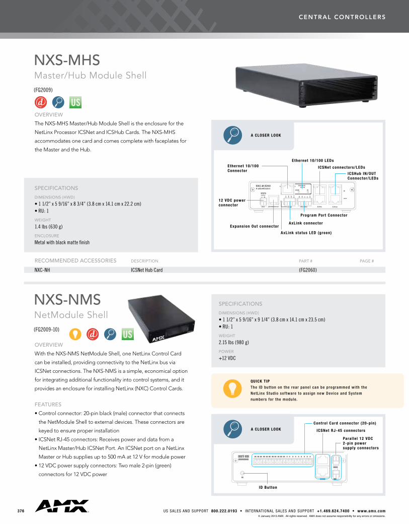
NXS-MHSMaster/Hub Module Shell(FG2009)
NXS-NMSNetModule Shell(FG2009-10)
OVERVIEW
TheNXS-MHSMaster/HubModuleShellistheenclosureforthe
NetLinx Processor ICSNet and ICSHub Cards. The NXS-MHS
accommodates one card and comes complete with faceplates for
the Master and the Hub.
SPECIFICATIONS
DIMENSIONS (HWD)
• 1 1/2” x 5 9/16” x 8 3/4” (3.8 cm x 14.1 cm x 22.2 cm)• RU: 1
WEIGHT
1.4 lbs (630 g)
ENCLOSURE
Metal with black matte finish
OVERVIEW
With the NXS-NMS NetModule Shell, one NetLinx Control Card
can be installed, providing connectivity to the NetLinx bus via
ICSNet connections. The NXS-NMS is a simple, economical option
for integrating additional functionality into control systems, and it
providesanenclosureforinstallingNetLinx(NXC)ControlCards.
FEATURES
•Controlconnector:20-pinblack(male)connectorthatconnects
the NetModule Shell to external devices. These connectors are
keyedtoensureproperinstallation
•ICSNetRJ-45connectors:Receivespoweranddatafroma
NetLinxMaster/HubICSNetPort.AnICSNetportonaNetLinx
MasterorHubsuppliesupto500mAat12Vformodulepower
•12VDCpowersupplyconnectors:Twomale2-pin(green)
connectorsfor12VDCpower
RECOMMENDED ACCESSORIES DESCRIPTION PART # PAGE #
NXC-NH ICSNet Hub Card (FG2060)
SPECIFICATIONS
DIMENSIONS (HWD)
• 1 1/2” x 5 9/16” x 9 1/4” (3.8 cm x 14.1 cm x 23.5 cm)• RU: 1
WEIGHT
2.15 lbs (980 g)
POWER
+12 VDC
QUICK TIP
The ID but ton on the rear panel can be programmed wi th the
NetL inx Studio sof tware to ass ign new Device and System
numbers for the module.
A CLOSER LOOK
S
Contro l Card connector (20-pin)
ICSNet RJ-45 connectors
ID Button
Paral le l 12 VDC2-pin powersupply connectors
A CLOSER LOOK
AXlink
AXP12VDC
PW R
M aster-EthernetNXC-M E260
GND
AXM
ETHERNET10/100
PROGRAM
PWR
RTS
CTS
SPEED
GND
TX RX
FD
ICSNet ICSHub
OUT
IN
Ethernet 10/100Connector
Ethernet 10/100 LEDs
ICSNet connectors/LEDs
Program Port Connector
AxLink connector
AxLink status LED (green)
Expansion Out connector
12 VDC power connector
ICSHub IN/OUTConnector/LEDs

central controllers
3773000 RESEARCH DRIVE, R ICHARDSON, TX 75082 • 800.222.0193 • 469.624.7153 fax • TECHNICAL SUPPORT 800.932.6993© January 2013 AMX. All rights reserved. AMX does not assume responsibility for any errors or omissions.
OVERVIEW
WhilethiscontrollercanserveasaconventionalRS-232/422
control port, it is also able to run its own Axcess application
program – an exclusive AMX product feature. Source specific
programming, such as video switchers, laserdisc players and video
codecs,canbehandledbytheAXB-232++todeliveramodular
solution for system programming.
SPECIFICATIONSDIMENSIONS (HWD)
1 1/2” x 5 9/16” x 5 7/16” (38 mm x 140 mm x 140 mm)
WEIGHT
1.1 lbs (499 g)
ENCLOSURE
Metal with black matte finish
CONTROL PORT
RS-232/422/485 port (300-115,200 baud), XON/XOFF, CTS/RTS
BUFFERS
1,000 byte serial input buffer; 1,000 byte AxLink buffer
INDICATORS
Three status LEDs indicate transmit, receive, and AxLink
OVERVIEW
TheAXB-DMX512createsabi-directionalDMX512-to-AxLink
connection,transmittingandreceivingupto512DMXchannels.
Onboardprocessingandmemorycreateasmanyas96channel
groups,eightfaders,and72presets(284byaddingextended
memory),aswellassoft-patchchannels.ADMXlightingboard
canoperateintandemwiththeAXB-DMX512,generatelevelsfor
storingpresets,orbypasstheAXB-DMX512fordirectcontrolof
channels.
SPECIFICATIONSDIMENSIONS (HWD)
1 1/2” x 5 9/16” x 5 7/16” (38.4 mm x 141 mm x 138.4 mm)
WEIGHT
1.1 lbs (499 g)
ENCLOSURE
Metal with black matte finish
CONTROL PORT
DMX512 transmit and receive
INCLUDES
Front-panel setup switches and status LEDs
AXB-232++RS-232/422/485 Interface(FG5761-10)
AXB-DMX512DMX512 Interface(FG5927)
RECOMMENDED ACCESSORIES DESCRIPTION PART # PAGE #
AC-RK Accessory Rack Kit (FG515) 410CC-232 Serial Communication Cable (FG10-752-04) 420
RECOMMENDED ACCESSORIES DESCRIPTION PART # PAGE #
AC-RK Accessory Rack Kit (FG515) 410
central controllers
378 US SALES AND SUPPORT 800.222.0193 • INTERNATIONAL SALES AND SUPPORT +1.469.624.7400 • www.amx.com© January 2013 AMX. All rights reserved. AMX does not assume responsibility for any errors or omissions.
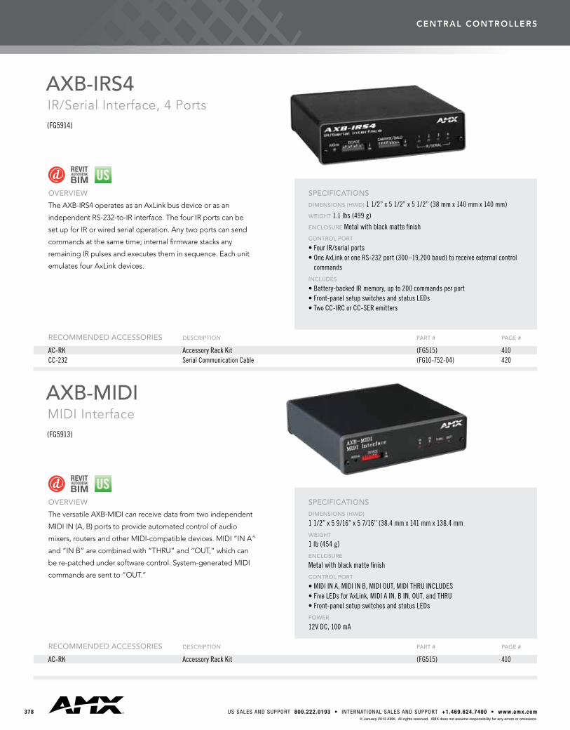
OVERVIEW
TheAXB-IRS4operatesasanAxLinkbusdeviceorasan
independent RS-232-to-IR interface. The four IR ports can be
set up for IR or wired serial operation. Any two ports can send
commandsatthesametime;internalfirmwarestacksany
remainingIRpulsesandexecutestheminsequence.Eachunit
emulatesfourAxLinkdevices.
SPECIFICATIONSDIMENSIONS (HWD) 1 1/2” x 5 1/2” x 5 1/2” (38 mm x 140 mm x 140 mm)
WEIGHT 1.1 lbs (499 g)
ENCLOSURE Metal with black matte finish
CONTROL PORT
• Four IR/serial ports• One AxLink or one RS-232 port (300–19,200 baud) to receive external control
commands
INCLUDES
• Battery-backed IR memory, up to 200 commands per port• Front-panel setup switches and status LEDs• Two CC-IRC or CC-SER emitters
OVERVIEW
TheversatileAXB-MIDIcanreceivedatafromtwoindependent
MIDIIN(A,B)portstoprovideautomatedcontrolofaudio
mixers,routersandotherMIDI-compatibledevices.MIDI“INA”
and“INB”arecombinedwith“THRU”and“OUT,”whichcan
bere-patchedundersoftwarecontrol.System-generatedMIDI
commandsaresentto“OUT.”
SPECIFICATIONSDIMENSIONS (HWD)
1 1/2” x 5 9/16” x 5 7/16” (38.4 mm x 141 mm x 138.4 mm
WEIGHT
1 lb (454 g)
ENCLOSURE
Metal with black matte finish
CONTROL PORT
• MIDI IN A, MIDI IN B, MIDI OUT, MIDI THRU INCLUDES• Five LEDs for AxLink, MIDI A IN, B IN, OUT, and THRU• Front-panel setup switches and status LEDs
POWER
12V DC, 100 mA
AXB-IRS4IR/Serial Interface, 4 Ports(FG5914)
AXB-MIDIMIDI Interface(FG5913)
RECOMMENDED ACCESSORIES DESCRIPTION PART # PAGE #
AC-RK Accessory Rack Kit (FG515) 410CC-232 Serial Communication Cable (FG10-752-04) 420
RECOMMENDED ACCESSORIES DESCRIPTION PART # PAGE #
AC-RK Accessory Rack Kit (FG515) 410

central controllers
3793000 RESEARCH DRIVE, R ICHARDSON, TX 75082 • 800.222.0193 • 469.624.7153 fax • TECHNICAL SUPPORT 800.932.6993© January 2013 AMX. All rights reserved. AMX does not assume responsibility for any errors or omissions.
OVERVIEW
TheAXB-VOL3controlsthreeaudiovolumechannels.Each
line-level channel, opto-isolated from system ground, can be
configured for balanced or unbalanced line operation. It is
programmablefor128stepsofaudiolevel,audiomute,variable
ramp speed and level presets.
SPECIFICATIONSDIMENSIONS (HWD)
1 1/2” x 5 7/16” x 5 7/16” (38.4 mm x 141 mm x 138.4 mm)
WEIGHT
1.1 lbs (499 g)
ENCLOSURE
Metal with black matte finish
AUDIO PORTS
• Three independent line-level audio in and out ports, balanced or unbalanced• THD of less than 0.008%, -72 dB at full attenuation (mute)
INCLUDES
• Front-panel setup switches and status LEDs• Resistors for 600 ohm termination
OVERVIEW
TheAXB-REL8controlsclosure-activateddevices,actingasan
eight-channelrelaycontrolportontheAxLinkbus.
SPECIFICATIONSDIMENSIONS (HWD)
1 1/2” x 5 1/2” x 5 1/2” (38 mm x 140 mm x 140 mm)
WEIGHT
1.1 lbs (499 g)
ENCLOSURE
Metal with black matte finish
CONTROL PORT
Eight relays, normally open, rated at 750 mA, 28 VAC/24 VDC
INCLUDES
• Front-panel device addressing switches and status LEDs• Metal tab strips for communing adjacent relays
AXB-VOL33-Channel Volume Controller(FG5756)
AXB-REL8Relay Controller(FG5774)
RECOMMENDED ACCESSORIES DESCRIPTION PART # PAGE #
AC-RK Accessory Rack Kit (FG515) 410
RECOMMENDED ACCESSORIES DESCRIPTION PART # PAGE #
AC-RK Accessory Rack Kit (FG515) 410
central controllers
380 US SALES AND SUPPORT 800.222.0193 • INTERNATIONAL SALES AND SUPPORT +1.469.624.7400 • www.amx.com© January 2013 AMX. All rights reserved. AMX does not assume responsibility for any errors or omissions.
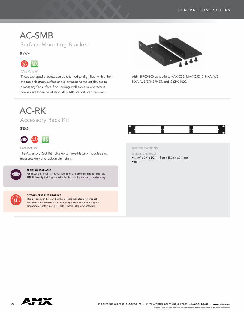
AC-SMBSurface Mounting Bracket(FG525)
OVERVIEW
TheseL-shapedbracketscanbeorientedtoalignflushwitheither
the top or bottom surface and allow users to mount devices to
almostanyflatsurface;floor,ceiling,wall,tableorwhereveris
convenientforaninstallation.AC-SMBbracketscanbeused
withNI-700/900controllers,MAX-CSE,MAX-CSD10,NXA-AVB,
NXA-AVB/ETHERNET,andIS-SPX-1000.
AC-RKAccessory Rack Kit(FG515)
OVERVIEW
TheAccessoryRackKitholdsuptothreeNetLinxmodulesand
measuresonlyonerackunitinheight.
SPECIFICATIONS
DIMENSIONS (HWD)
• 1 3/4” x 19” x 1/2” (4.4 cm x 48.3 cm x 1.3 cm)• RU: 1
D-TOOLS CERTIFIED PRODUCT
This product can be found in the D-Too ls manufacturer product
da tabase and spec i f ied as a th i rd par ty dev ice when bu i ld ing and
propos ing a sys tem us ing D-Too ls Sys tem In tegra tor so f tware .
TRAINING AVAILABLE
For impor tant ins ta l la t ion , conf igura t ion and programming techn iques ,
AMX Un ivers i ty t ra in ing is ava i lab le . Jus t v is i t www.amx.com/tra in ing

central controllers
3813000 RESEARCH DRIVE, R ICHARDSON, TX 75082 • 800.222.0193 • 469.624.7153 fax • TECHNICAL SUPPORT 800.932.6993© January 2013 AMX. All rights reserved. AMX does not assume responsibility for any errors or omissions.
NXP-CPI16NetLinx® Custom Panel Interface(FG2410)
OVERVIEW
The NetLinx Custom Panel Interface provides a direct ICSNet
connectiontocustomcontrolpanels.It’spin-for-pincompatible
withdevicesthatweredesignedforusewiththeAXP-CPI16card
(designedforintegrationwithanAxcessControlSystem).Two20-
pin headers provide ribbon cable wiring or direct-connect inser-
tiontocircuitboards,providinginputsforupto16closuresand
16feedbackoutputsforLEDs.Undersoftwarecontrol,theLED
outputscanactasdriversto8-segmentbargraphsorasdiscrete
outputsforfeedback.Inaddition,theNXC-CPI16alsoincludes
two quadrature inputs for mechanical or optical rotary encoders,
used to control variable levels such as volume and lights, or lens
focusandzoom.
COMMON APPLICATION
TheNXP-CPI16isaversatile,usefuldeviceforbothcustompanel
and contact-closure applications.
FEATURES
•Integratescustompanelswith16closureinputsand16LED
outputs; pin-for-pin compatible with panels designed for
AXP-CPI16
•Operatesasalow-costclosureinterface
•Actsasadriverforuptotwo8-segmentLEDbargraphs;each
bargraphuseseightofthe16LEDoutputs
•Allowsprecisedigitalcontrolofuptotwolevelsfrom
quadrature inputs
•Acceptsmechanicaloropticalrotaryencoders
•Offersprogrammablelevelresponse,providessoftware-driven
performanceadjustmentandswitchablecoarse/finelevelcontrol
SPECIFICATIONS
DIMENSIONS (HWD)
2 3/4” x 1 7/8” x 1 3/8” (7.0 cm x 4.7 cm x 3.6 cm)
WEIGHT
• Device: 8.10 oz (229.6 g)• Total Shipping: 1 lb (453.6 g)
POWER
12 VDC; maximum draw of 300 mA
INPUT CONNECTORS
• Indicator power: Two-pin 3.5 mm captive wire• I/O Headers: Two 20-pin headers, 8 I/O channels each (16 closure inputs activated with GND or TTL Low (< 0.8 V)). Open collector outputs (0-28 VDC). Inputs are sampled approximately every 10 msec• Rotary Encoder inputs: 2 Quadrature inputs on a 2 x 3 header (6-pin), two encoder inputs (4-pin) with a +5 V supply pin (supplying up to 100 mA) and a GND pin
ICSNET
• Two RJ-45 connectors for ICSNet connection ID BUTTON• Generates an event from the CPI16 to allow you to assign new device numbers using the ID mode in NetLinx Studio
LED
ICSP status indicator (green)
OPEN COLLECTOR OUTPUTS
• 16-open collector outputs, acting as a switch to ground, up to 100 mA. • Outputs can be connected to voltages ranging between 0 and + 28 V. • Each output is updated every 10 msec
INCLUDED ACCESSORIES
• 6-pin header with 3 feet (0.914) of ribbon cable• Two mating 20-pin headers, each with 3 feet of ribbon cable attached• One green 2-pin 3.5 mm pitch captive wire connector for external indicator power
central controllers
382 US SALES AND SUPPORT 800.222.0193 • INTERNATIONAL SALES AND SUPPORT +1.469.624.7400 • www.amx.com© January 2013 AMX. All rights reserved. AMX does not assume responsibility for any errors or omissions.
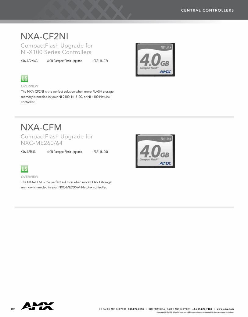
NXA-CF2NICompactFlash Upgrade for NI-X100 Series ControllersNXA-CF2NI4G 4 GB CompactFlash Upgrade (FG2116-07)
NXA-CFMCompactFlash Upgrade for NXC-ME260/64NXA-CFM4G 4 GB CompactFlash Upgrade (FG2116-06)
OVERVIEW
TheNXA-CF2NIistheperfectsolutionwhenmoreFLASHstorage
memoryisneededinyourNI-2100,NI-3100,orNI-4100NetLinx
controller.
OVERVIEW
TheNXA-CFMistheperfectsolutionwhenmoreFLASHstorage
memoryisneededinyourNXC-ME260/64NetLinxcontroller.
central controllers
3833000 RESEARCH DRIVE, R ICHARDSON, TX 75082 • 800.222.0193 • 469.624.7153 fax • TECHNICAL SUPPORT 800.932.6993© January 2013 AMX. All rights reserved. AMX does not assume responsibility for any errors or omissions.
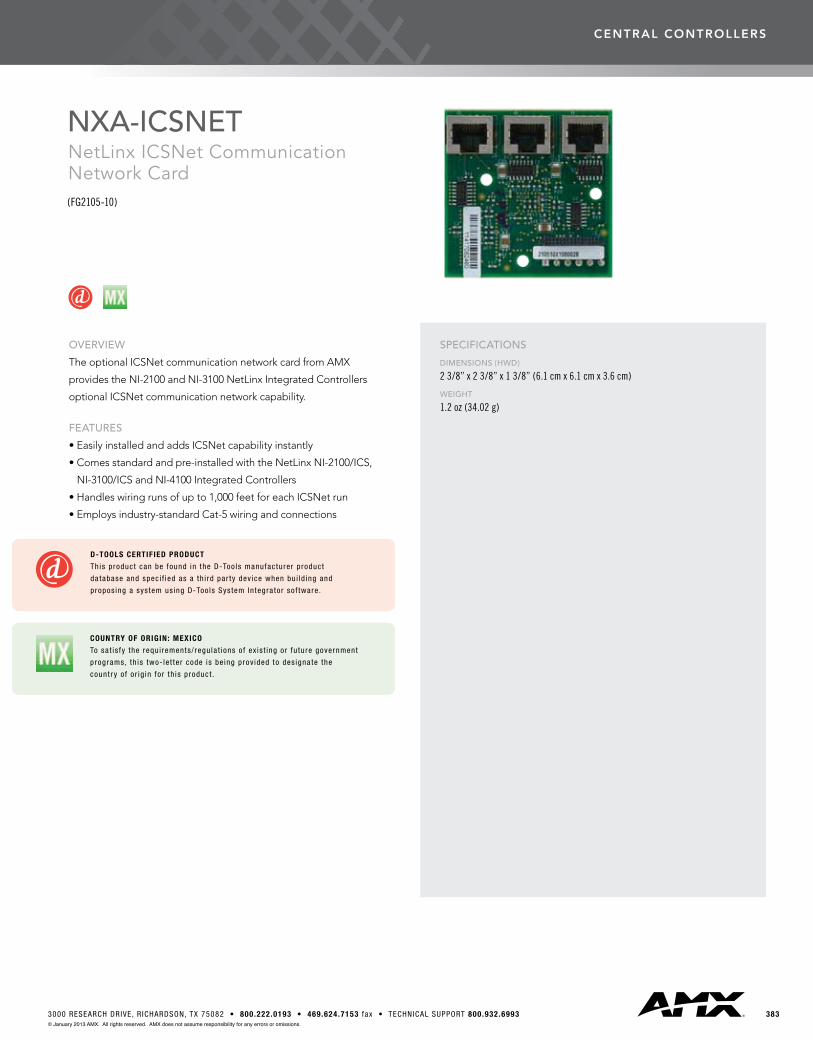
NXA-ICSNETNetLinx ICSNet Communication Network Card(FG2105-10)
OVERVIEW
TheoptionalICSNetcommunicationnetworkcardfromAMX
providestheNI-2100andNI-3100NetLinxIntegratedControllers
optionalICSNetcommunicationnetworkcapability.
FEATURES
•EasilyinstalledandaddsICSNetcapabilityinstantly
•Comesstandardandpre-installedwiththeNetLinxNI-2100/ICS,
NI-3100/ICSandNI-4100IntegratedControllers
•Handleswiringrunsofupto1,000feetforeachICSNetrun
•Employsindustry-standardCat-5wiringandconnections
SPECIFICATIONS
DIMENSIONS (HWD)
2 3/8” x 2 3/8” x 1 3/8” (6.1 cm x 6.1 cm x 3.6 cm)
WEIGHT
1.2 oz (34.02 g)
D-TOOLS CERTIFIED PRODUCT
This product can be found in the D-Too ls manufacturer product
da tabase and spec i f ied as a th i rd par ty dev ice when bu i ld ing and
propos ing a sys tem us ing D-Too ls Sys tem In tegra tor so f tware .
COUNTRY OF ORIGIN: MEXICO
To sa t is fy the requ i rements / regu la t ions o f ex is t ing or fu ture government
programs, th is two- le t te r code is be ing prov ided to des igna te the
count r y o f o r ig in fo r th is product .