central coast council – ulverstone, penguin, north west ......linen hanging/ shelving hanging/...
TRANSCRIPT


SEARCH DATE : 28-Jan-2020SEARCH TIME : 11.01 AM
DESCRIPTION OF LAND Parish of BRADWORTHY, Land District of DEVON Lot 1 on Plan 110463 Being the land described in Conveyance No. 55/2968 Derivation : Part of Lot 349, 500 Acres Gtd. to R H Douglas Derived from A12999
SCHEDULE 1 C246357 TRANSFER to PETER DOUGLAS LANGMAID and ALANA ROSE LANGMAID Registered 25-Aug-2000 at 12.03 PM
SCHEDULE 2 Reservations and conditions in the Crown Grant if any C893487 BURDENING WAYLEAVE EASEMENT with the benefit of a restriction as to user of land in favour of Aurora Energy Pty Ltd over the land marked Wayleave Easement 12.00 wide on P.110463 (Subject to Provisions) Registered 03-Mar-2009 at noon
UNREGISTERED DEALINGS AND NOTATIONS No unregistered dealings or other notations
SEARCH OF TORRENS TITLE
VOLUME
110463FOLIO
1
EDITION
4DATE OF ISSUE
03-Mar-2009
RESULT OF SEARCHRECORDER OF TITLES
Issued Pursuant to the Land Titles Act 1980
Department of Primary Industries, Parks, Water and Environment www.thelist.tas.gov.auPage 1 of 1

FOLIO PLANRECORDER OF TITLES
Issued Pursuant to the Land Titles Act 1980
Search Date: 28 Jan 2020 Search Time: 11:02 AM Volume Number: 110463 Revision Number: 02
Department of Primary Industries, Parks, Water and Environment www.thelist.tas.gov.auPage 1 of 1
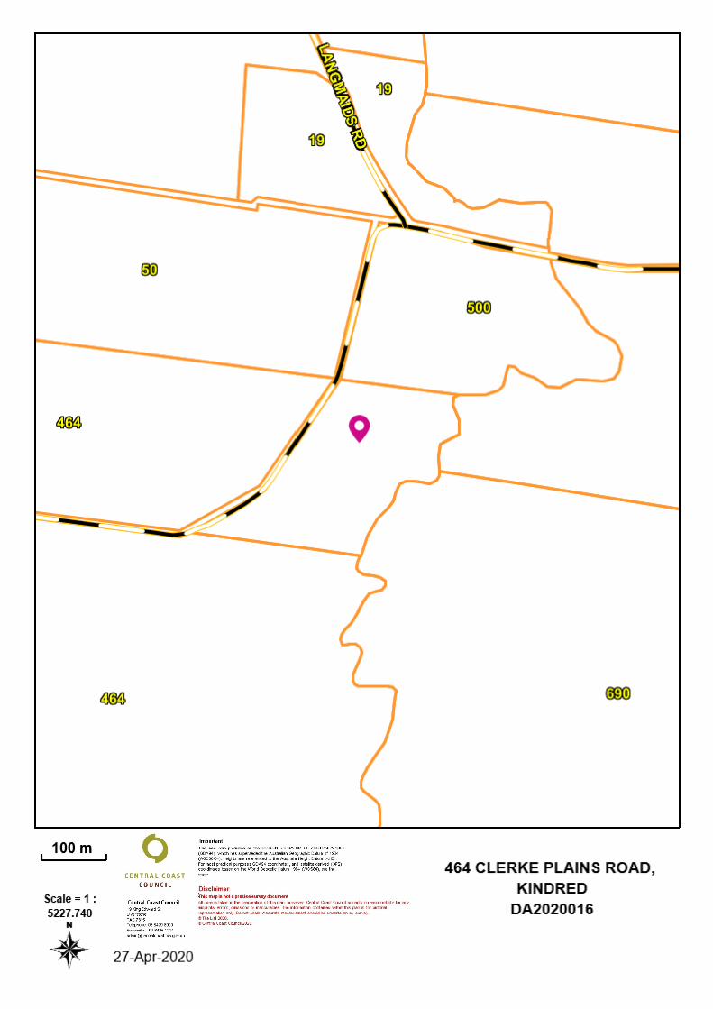
110463/1
26 RURAL RESOURCES
-
-
7
-
-
-
-
-
-
-
-
-
-
PROJECT NUMBER:
LACHLAN WALSH DESIGNTasmania Accreditation Number: CC 6162 E
ABN: 94 660 558 746
PO Box 231, Devonport TAS, 7310
E: [email protected] | P: 6424 8053
DO NOT SCALE DRAWINGS
CONTRACTOR TO VERIFY ALL DIMENSIONS AND HIGHTS ON SITE PRIOR TO COMMENCEMENT OF ANY WORKS
IT IS THE CONTRACTOR'S RESPONSIBILITY TO CONTACT ALL RELEVANT AUTHORITIES AND OBTAIN APPROVALS FOR
ALL WORKS
ALL PRODUCTS NOTED IN THIS SET OF DRAWINGS TO BE CONFIRMED BY THE CLIENT AND/OR SUPERINTENDENT OF
THE PROJECT BEFORE PURCHASING AND/OR INSTALLING OF PRODUCT
QUANTITIES INDICATED IN THIS SET OF DRAWINGS ARE A GUIDE ONLY, CONTRACTORE TO CALCULATE AND
CONFIRM QUANTITY AMOUNTS BEFORE PURCHASING
© COPYRIGHT
CONDITIONS OF USE: This document may only be used by LWD's client (and any other person qho LWD has agreed
can use this document) for the purpose for which it was prepared and must not be used by any other person or
replicated for any other purpose.
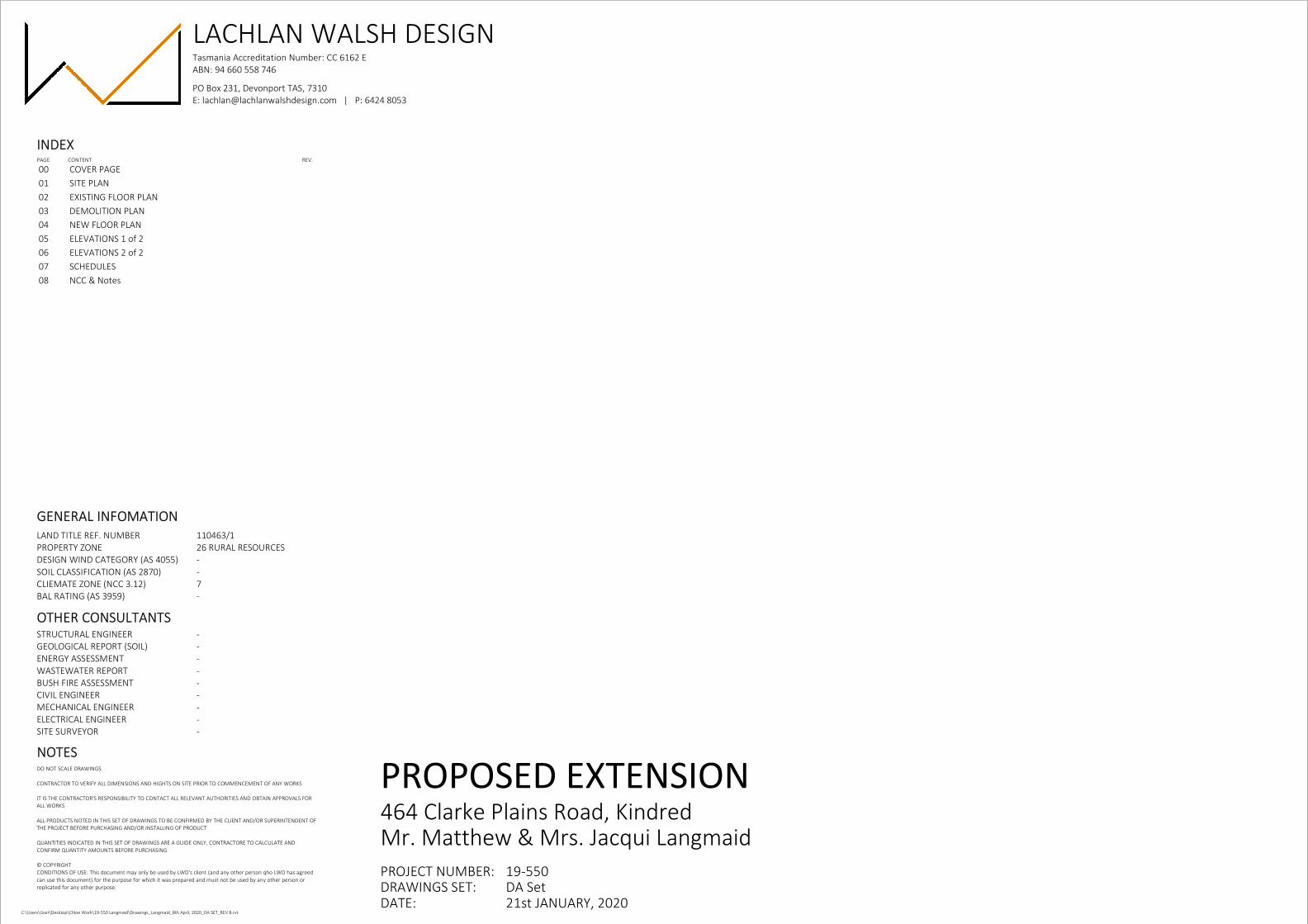
INDEXPAGE CONTENT REV.
GENERAL INFOMATION
OTHER CONSULTANTS
DRAWINGS SET:
LAND TITLE REF. NUMBER
PROPERTY ZONE
DESIGN WIND CATEGORY (AS 4055)
SOIL CLASSIFICATION (AS 2870)
CLIEMATE ZONE (NCC 3.12)
BAL RATING (AS 3959)
STRUCTURAL ENGINEER
GEOLOGICAL REPORT (SOIL)
ENERGY ASSESSMENT
WASTEWATER REPORT
BUSH FIRE ASSESSMENT
CIVIL ENGINEER
MECHANICAL ENGINEER
ELECTRICAL ENGINEER
SITE SURVEYOR
NOTES
DATE:C:\Users\User\Desktop\Chloe Work\19-550 Langmaid\Drawings_Langmaid_8th April, 2020_DA SET_REV B.rvt
PROPOSED EXTENSION464 Clarke Plains Road, KindredMr. Matthew & Mrs. Jacqui Langmaid
19-550DA Set21st JANUARY, 2020
00 COVER PAGE
01 SITE PLAN
02 EXISTING FLOOR PLAN
03 DEMOLITION PLAN
04 NEW FLOOR PLAN
05 ELEVATIONS 1 of 2
06 ELEVATIONS 2 of 2
07 SCHEDULES
08 NCC & Notes

PROPOSED EXTENSION
& DECK
EXISTING RESIDENCE
EXISTING
SHED
EXISTING
SHED
CLERKE P
LAIN
S RO
AD
42
71
64316
PROPOSED TRENCHES FOR DISPOSAL OF WASTE
WATER, PLEASE REFER TO WASTE WATER
MANAGEMENT REPORT FOR FULL DETAILS
EXISTING WATER TANK FOR
COLLECTION OF STORM WATER
NOTESALL FLOOR TO FINISHED GROUND LEVELS HEIGHTS AND SITE
CONTOURS NEED TO BE CONFIRMED ON SITE BEFORE START OF
CONSTRUCTION, AS SHOWN ARE A GUIDE ONLY.
ALL PLUMBING WORK TO BE DONE MUST BE COMPLETED BY A
LICENSED PLUMBER.
SYMBOLSTASWATER & COUNCIL MAINS (S.W. / S.
/ W.M.)
MAN HOLE COVER
VEGETATION
SOIL & WATER MANAGEMENTDOWN PIPES TO BE CONNECTED INTO COUNCIL STORM WATER
OR TO SITE STORM WATER DISCHARGE AREA AS SOON AS ROOF IS
INSTALLED.
EXCAVATED MATERIAL TO HAVE SEDIMENT CONTROL BARRIER TO
BE INSTALLED DOWN-SLOPE. EXCAVATED MATERIAL TO BE
REMOVED AT COMPLETION OF BUILDING WORKS AND/OR USED
AS FILL ON SITE FOR ANY LOW POINTS.
CRUSHED ROCK TO BE APPLIED AT ENTRY TO SITE FOR SEDIMENT
CONTROL AND TO PREVENT TRANSFERRING DEBRIS ONTO STREET.
REAPPLY CRUSHED ROCK TO ENTRY IF EXCESSIVE SEDIMENT
BUILD-UP OCCURS.
AREA SCHEDULE
M.H.C.
NEIGHBOURING PROPERTYNEIGHBOURING PROPERTY
NEIGHBOURING PROPERTY
NEIGHBOURING PROPERTY
NEIGHBOURING PROPERTY
PROPERTY DAM
CLE
RK
E P
LAIN
S R
OA
D
CLERKE P
LAIN
S RO
AD
264.000+/-
184.544+/-
33
8.0
31
+/-
20
2.2
91
+/-
TITLE PROJECT
LOCATION
CLIENT
PROJECT NO.
LACHLAN WALSH DESIGNTasmania Accreditation Number: CC 6162 E
ABN: 94 660 558 746
PO Box 231, Devonport TAS, 7310
E: [email protected] | P: 6424 8053SCALE
A3
DATE
DRAWINGS SET REV. NO.PAGE NO. PAGE SIZE
DRAWN BY
CHECKED BY
DO NOT SCALE DRAWINGS
CONTRACTOR TO VERIFY ALL DIMENSIONS AND HIGHTS
ON SITE PRIOR TO COMMENCEMENT OF ANY WORKS
IT IS THE CONTRACTOR'S RESPONSIBILITY TO CONTACT
ALL RELEVANT AUTHORITIES AND OBTAIN APPROVALS
FOR ALL WORKS
© COPYRIGHT
NO. DATE REVISION BY
As indicatedC:\Users\User\Desktop\Chloe Work\19-550 Langmaid\Drawings_Langmaid_8th April, 2020_DA SET_REV B.rvt
PROPOSED EXTENSION
464 Clarke Plains Road, Kindred
Mr. Matthew & Mrs. Jacqui Langmaid
21st JANUARY, 2020
SITE PLAN 19-550
DA Set01
C. FEBEY
L.WALSH
LOCATION AREA
EXISTING RESIDENCE 116.7m2 (12.5 sqs)
PROPOSED EXTENSION 58.7m² (6.3 Sq)
BUILDING TOTAL 175.4m2 (18.8sqs)
DECK & PATH 78.0m2 (8.3 sqs)
LOCAL SITE PLANSCALE: 1:500
SITE PLANSCALE: 1:5000
BEFORE BUILDING AND PLUMBIG PERMITS
ARE ISUBMITTED LOCATION AND SIZE OF
WASTE WATER AND SEPTIC IS TO BE ASSESSED
BY ENGINEER

14 m²e' BEDROOM 2
Cp
12 m²e' OFFICE
Cp
10 m²e' BEDROOM 1
Cp
7 m²e' BATH
Ti
e' KITCHEN/ DINING
24m2
VF
e' LIVING
19m2
Cp
e' LAUNDRY
3.9m2
VF
e' ENTRY
1.7m2
VF
e' HALL
6.8m2
VF
4140
90304240
240377090209090890903170903080
6415
24
03
38
09
02
76
09
057
03
37
02
40
10
74
0
1070 240 240
13840
13840 3000
72
70
67
90
3000 EXISTING 110mm BRICK WORK, 40mm CAVITY,
90mm STUD WALL (INTERNAL), INSULATION,
10mm PLASTERBOARD
90mm STUD WALLS, 10mm PLASTERBOARD
LINING ON ALL UNLESS NOTED OTHER
CLADDING (TYP) 90mm STUD WALL (INTERNAL),
INSULATION, 10mm PLASTERBOARD UNLESS
NOTED OTHER
110mm BRICK WORK (TYP), 40mm CAVITY,
90mm STUDWALL (INTERNAL), INSULATION,
10mm PLASTERBOARD UNLESS NOTED OTHER
FINISH FLOOR OR GROUND HIGH
WINDOW No. (REFER TO WINDOW SCHEDUAL)
DOOR No. (REFER TO WINDOW SCHEDUAL)
ELEVATION ORENTATION (REFER TO RELEVENT
PAGE)
Cp CARPET, REFER TO FINISHES PLAN
Ti SELECTED TILE FLOORING, REFER TO FINISHES
PLAN
C CONCRETE FLOORING, REFER TO FINISHES PLAN
1400
W1
D1
N03
NOTESALL JOINERY DESIGNED AND DOCUMENTS BY OTHER. ALL
APPLIANCES TO BE SELECTED BY CLIENT AND/OR
SUPERINTENDENT.
ALL GLAZED WINDOW AND DOOR ASSEMBLIES IN EXTERNAL
WALLS TO COMPLY WITH AS 2047. ALL OTHER GLASS TO COMPLY
WITH AS 1288
FLYSCREENS TO BE FITTED TO ALL OPENABLE WINDOWS AND
DOORS.
ALL PRODUCTS & MATERIALS NOTED OR SPECIFIED BY CLIENT
AND/OR SUPERINTENDENT ARE TO BE INSTALLED IN STRICT
ACCORDANCE WITH MANUFACTURES DETAILS, INSTRUCTIONS
AND SPECIFICATIONS.
SYMBOLS
TITLE PROJECT
LOCATION
CLIENT
PROJECT NO.
LACHLAN WALSH DESIGNTasmania Accreditation Number: CC 6162 E
ABN: 94 660 558 746
PO Box 231, Devonport TAS, 7310
E: [email protected] | P: 6424 8053SCALE
A3
DATE
DRAWINGS SET REV. NO.PAGE NO. PAGE SIZE
DRAWN BY
CHECKED BY
DO NOT SCALE DRAWINGS
CONTRACTOR TO VERIFY ALL DIMENSIONS AND HIGHTS
ON SITE PRIOR TO COMMENCEMENT OF ANY WORKS
IT IS THE CONTRACTOR'S RESPONSIBILITY TO CONTACT
ALL RELEVANT AUTHORITIES AND OBTAIN APPROVALS
FOR ALL WORKS
© COPYRIGHT
NO. DATE REVISION BY
1 : 100C:\Users\User\Desktop\Chloe Work\19-550 Langmaid\Drawings_Langmaid_8th April, 2020_DA SET_REV B.rvt
PROPOSED EXTENSION
464 Clarke Plains Road, Kindred
Mr. Matthew & Mrs. Jacqui Langmaid
21st JANUARY, 2020
EXISTING FLOOR PLAN 19-550
DA Set02
Author
Checker
EXISTING FLOOR PLANSCALE: 1:100

REMOVE EXISTING ROOF AREA, MAKE GOOD
REMAING SURFACES FOR FUTURE WORK
DEMOLISH EXISTING EXTERNAL WALL, MAKE
EXISTING EXPOSED SERFACES GOOD FOR NEW
WORKS
REMOVE EXISTING DECK AREA, MAKE GOOD
REMAINING SURFACES FOR FUTURE WORKS
REMOVE EXISTING ROOF SHEETING, BATTENS AND
TRUSSES. MAKE GOOD FOR NEW TRUSSES AND ROOF
SHEETING
BRACE REMAINING WALL FOR THE REMOVAL OF
ROOF TRUSSES AND POSSIBLE ROOF BRACING. MAKE
AREA GOOD FOR FUTURE WORKS
REMOVE EXISTING INTERIOR WALLS, BRACE
REMAINNG WALLS FOR FUTURE WORKS
10 m²e' BEDROOM 1
Cp
12 m²e' OFFICE
Cp
BEDROOM 212m Cp
7 m²e' BATH
Ti
WALLS OR OBJECTS TO BE REMOVED OR
DEMOLISHED
DEMOLITION IS NOT TO COMMENCE UNTIL DEMOLITION
CONTRACTOR HAS BEEN ADVISED THAT ALL ELECTRICAL SUPPLIES
HAVE BEEN DISCONNECTED AND ISOLATED.
ALL DEMOLITION IS TO BE CARRIED OUT IN A SAFE AND
WORKMAN LIKE MANNER.
IT IS THE DEMOLITION CONTRACTORS RESPONSIBILITY TO
PROVIDE SUFFICIENT PROPS, STAYS & THE LIKE TO PROTECT
REMAINING STRUCTURE. IF IN DOUBT SEEK ADVICE FROM A
STRUCTURAL ENGINEER.
THE DEMOLISHER IS TO PREVENT BUILDING MATERIAL AND
DEBRIS FROM FALLING ONTO OR INTO ADJACENT STREETS AND
PROPERTIES.
CAP ALL REDUNDANT SERVICES, REMOVE PIPEWORK WHERE
PRACTICAL & LOCATE AND MARK POSITIONS OF
PIPEWORK/SERVICES REQUIRED FOR USE IN NEW WORKS.
ALL ASBESTOS MATERIAL FOUND IS TO BE CONTROLLED AND
REMOVED FROM SITE IN ACCORDANCE WITH ALL REGULATORY
AUTHORITIES HAVING JURISDICTION OF THESE WORKS BEFORE
COMMENCING FURTHER WORKS.
IT IS THE BUILDERS RESPONSIBILITY TO LOCATE AND PROTECT ALL
EXISTING SERVICES PRIOR TO COMMENCING ANY EXCAVATIONS.
NOTES
TITLE PROJECT
LOCATION
CLIENT
PROJECT NO.
LACHLAN WALSH DESIGNTasmania Accreditation Number: CC 6162 E
ABN: 94 660 558 746
PO Box 231, Devonport TAS, 7310
E: [email protected] | P: 6424 8053SCALE
A3
DATE
DRAWINGS SET REV. NO.PAGE NO. PAGE SIZE
DRAWN BY
CHECKED BY
DO NOT SCALE DRAWINGS
CONTRACTOR TO VERIFY ALL DIMENSIONS AND HIGHTS
ON SITE PRIOR TO COMMENCEMENT OF ANY WORKS
IT IS THE CONTRACTOR'S RESPONSIBILITY TO CONTACT
ALL RELEVANT AUTHORITIES AND OBTAIN APPROVALS
FOR ALL WORKS
© COPYRIGHT
NO. DATE REVISION BY
As indicatedC:\Users\User\Desktop\Chloe Work\19-550 Langmaid\Drawings_Langmaid_8th April, 2020_DA SET_REV B.rvt
PROPOSED EXTENSION
464 Clarke Plains Road, Kindred
Mr. Matthew & Mrs. Jacqui Langmaid
21st JANUARY, 2020
DEMOLITION PLAN 19-550
DA Set03
C. FEBEY
L.WALSH
DEMOLITION PLANSCALE: 1:100

06N
05
W
05 S
3500
13
10
33
80
90
27
60
57
09
03
37
0
33
80
90
32
10
90
11
10
90
22
90
90
99
02
38
03
33
0
10
26
0
10
26
0
4260 90 3920 90
33
80
90
32
10
90
11
10
90
22
90
06
1
2406810
1410
PANTRYFRIDGE
1600
BENCH SEAT
----
651090191090121090317090
591090232090181090600100090
15650
5010
70
20
W0
1D
01
W0
2
W03
W05 W06 W07W04
3 m²LAUNDRY
Ti7 m²BATH.
Ti
10 m²BEDROOM 1
Cp
12 m²OFFICE
Cp
11 m²BEDROOM 2
Cp
13 m²M. BEDROOM
Cp
5 m²W.I.R.
Cp
6 m²ENS.
Ti
10 m²HALLWAY
VF
3 m²ENTRY
VF
33 m²LIVING / DINING
VF
10 m²KITCHEN
VF
BULK HEADLI
NE
N
HA
NG
ING
/ SH
ELV
ING
HANGING/ SHELVING
HA
NG
ING
/ SH
ELV
ING
STORAGEROBE
ROBE
1500
D03
D0
5
D0
8
D06
D0
7
D09
D04
D02
Col.1 Col.1Col.1
Col.1
Col.1
Col.1Col.1
Col.1
Col.1
Col.1
Col.1
TIMBER SCREEN WALL
1 METER HIGHT STAINLESS
STEEL WIRE BALUSTRADING
89X 89 S.H.S POST, POWDER COATED FINISH,
COLOUR TO BE SELECTED BY CLIENT
EXISTING 110mm BRICK WORK, 40mm CAVITY,
90mm STUD WALL (INTERNAL), INSULATION,
10mm PLASTERBOARD
90mm STUD WALLS, 10mm PLASTERBOARD
LINING ON ALL UNLESS NOTED OTHER
CLADDING (TYP) 90mm STUD WALL (INTERNAL),
INSULATION, 10mm PLASTERBOARD UNLESS
NOTED OTHER
110mm BRICK WORK (TYP), 40mm CAVITY,
90mm STUDWALL (INTERNAL), INSULATION,
10mm PLASTERBOARD UNLESS NOTED OTHER
FINISH FLOOR OR GROUND HIGH
WINDOW No. (REFER TO WINDOW SCHEDUAL)
DOOR No. (REFER TO WINDOW SCHEDUAL)
ELEVATION ORENTATION (REFER TO RELEVENT
PAGE)
Cp CARPET, REFER TO FINISHES PLAN
Ti SELECTED TILE FLOORING, REFER TO FINISHES
PLAN
C CONCRETE FLOORING, REFER TO FINISHES PLAN
1400
W1
D1
N03
NOTESALL JOINERY DESIGNED AND DOCUMENTS BY OTHER. ALL
APPLIANCES TO BE SELECTED BY CLIENT AND/OR
SUPERINTENDENT.
ALL GLAZED WINDOW AND DOOR ASSEMBLIES IN EXTERNAL
WALLS TO COMPLY WITH AS 2047. ALL OTHER GLASS TO COMPLY
WITH AS 1288
FLYSCREENS TO BE FITTED TO ALL OPENABLE WINDOWS AND
DOORS.
ALL PRODUCTS & MATERIALS NOTED OR SPECIFIED BY CLIENT
AND/OR SUPERINTENDENT ARE TO BE INSTALLED IN STRICT
ACCORDANCE WITH MANUFACTURES DETAILS, INSTRUCTIONS
AND SPECIFICATIONS.
SYMBOLS
TITLE PROJECT
LOCATION
CLIENT
PROJECT NO.
LACHLAN WALSH DESIGNTasmania Accreditation Number: CC 6162 E
ABN: 94 660 558 746
PO Box 231, Devonport TAS, 7310
E: [email protected] | P: 6424 8053SCALE
A3
DATE
DRAWINGS SET REV. NO.PAGE NO. PAGE SIZE
DRAWN BY
CHECKED BY
DO NOT SCALE DRAWINGS
CONTRACTOR TO VERIFY ALL DIMENSIONS AND HIGHTS
ON SITE PRIOR TO COMMENCEMENT OF ANY WORKS
IT IS THE CONTRACTOR'S RESPONSIBILITY TO CONTACT
ALL RELEVANT AUTHORITIES AND OBTAIN APPROVALS
FOR ALL WORKS
© COPYRIGHT
NO. DATE REVISION BY
1 : 100C:\Users\User\Desktop\Chloe Work\19-550 Langmaid\Drawings_Langmaid_8th April, 2020_DA SET_REV B.rvt
PROPOSED EXTENSION
464 Clarke Plains Road, Kindred
Mr. Matthew & Mrs. Jacqui Langmaid
21st JANUARY, 2020
NEW FLOOR PLAN 19-550
DA Set04
C. FEBEY
L. WALSH
FLOOR PLANSCALE: 1:100

FINISH FLOOR OR GROUND HIGH
WINDOW No. (REFER TO WINDOW SCHEDUAL)
DOOR No. (REFER TO WINDOW SCHEDUAL)
M.B. METER BOX
S SLIDING WINDOWS
A AWNING WINDOWS
F FIXED WINDOW
O/A OPAQUE AWNING WINDOW
O/F OPAQUE FIXED WINDOW
1400
W1
D1
NOTESALL GLAZED WINDOW AND DOOR ASSEMBLIES IN EXTERNAL
WALLS TO COMPLY WITH AS 2047. ALL OTHER GLASS TO COMPLY
WITH AS 1288
REFER TO WINDOW SCHEDULES FOR WINDOW SIZE & TYPE.
FLYSCREENS TO BE FITTED TO ALL OPENABLE WINDOWS AND
DOORS.
ALL PRODUCTS & MATERIALS NOTED ARE TO BE INSTALLED IN
STRICT ACCORDANCE WITH MANUFACTURES DETAILS,
INSTRUCTIONS AND SPECIFICATIONS.
SYMBOLS
FLASHING TO WALL OPENINGS
ALL OPENINGS MUST BE ADEQUATELY FLASHED USING MATERIALS
THAT COMPLY WITH AS/NZS 2904. FLASHING TO BE INSTALLED
WITH GLAZING MANUFACTURER'S SPECIFICATIONS FOR BRICK
VENEER OR LIGHT WEIGHT CLADDING CONSTRUCTION.
FFL.
FCL.1
FRL.1
19
25
24
00
43
25
COLORBOND TRIMLINE QUOD TYPE
GUTTER WITH SLOTTED FRONT,
COLOUR TO BE SELECTED BY CLIENT
COLORBOND CUSTEM ORB ROOF
SHEETING, COLOUR TO BE SELECTED
BY CLIENT
STRIA CLADDING OR SIMILAR,
PAINTED FINISH,COLOUR
SELECTED BY CLIENT
LASERLITE ROOFING SHEETS TO
UNDERCOVER AREA
12°
5°
EXISTING BRICK, REMOVED TO
2400mm TO ALLOW FOR NEW
ROOF TRUSSES AND LIGHT CLAD
FFL.
FCL.1
FRL.1
WINDOWS & DOOR FRAMES TO
BE POWDER COATED ALUMINIUM,
COLOUR TO BE "MONUMENT"
COLORBOND TRIMLINE QUOD TYPE
GUTTER WITH SLOTTED FRONT,
COLOUR TO BE SELECTED BY CLIENT
COLORBOND CUSTOM ORB ROOF
SHEETING, COLOUR TO BE SELCTED
BYCLIENT
STRIA CLADDING OR SIMILAR,
PAINTED FINISH,COLOUR
SELECTED BY CLIENT
TIMBER DECKING SCREENING,
TIMBER TO BE SELECTED BY CLIENT
LASERLITE ROOFING SHEETS TO
UNDERCOVER AREA
W07 W06
W05 W04
A
F
F F
F
A AA1
92
52
40
0
43
25
NEW BRICK VENEER TO MATCH IN
WITH THE EXISTING
34
0
TITLE PROJECT
LOCATION
CLIENT
PROJECT NO.
LACHLAN WALSH DESIGNTasmania Accreditation Number: CC 6162 E
ABN: 94 660 558 746
PO Box 231, Devonport TAS, 7310
E: [email protected] | P: 6424 8053SCALE
A3
DATE
DRAWINGS SET REV. NO.PAGE NO. PAGE SIZE
DRAWN BY
CHECKED BY
DO NOT SCALE DRAWINGS
CONTRACTOR TO VERIFY ALL DIMENSIONS AND HIGHTS
ON SITE PRIOR TO COMMENCEMENT OF ANY WORKS
IT IS THE CONTRACTOR'S RESPONSIBILITY TO CONTACT
ALL RELEVANT AUTHORITIES AND OBTAIN APPROVALS
FOR ALL WORKS
© COPYRIGHT
NO. DATE REVISION BY
1 : 100C:\Users\User\Desktop\Chloe Work\19-550 Langmaid\Drawings_Langmaid_8th April, 2020_DA SET_REV B.rvt
PROPOSED EXTENSION
464 Clarke Plains Road, Kindred
Mr. Matthew & Mrs. Jacqui Langmaid
21st JANUARY, 2020
ELEVATIONS 1 of 2 19-550
DA Set05
C.FEBEY
L.WALSH
SOUTH ELEVATIONSCALE: 1:100
WEST ELEVATIONSCALE: 1:100
EXISTING WINDOWS TO REMAIN

FINISH FLOOR OR GROUND HIGH
WINDOW No. (REFER TO WINDOW SCHEDUAL)
DOOR No. (REFER TO WINDOW SCHEDUAL)
M.B. METER BOX
S SLIDING WINDOWS
A AWNING WINDOWS
F FIXED WINDOW
O/A OPAQUE AWNING WINDOW
O/F OPAQUE FIXED WINDOW
1400
W1
D1
NOTESALL GLAZED WINDOW AND DOOR ASSEMBLIES IN EXTERNAL
WALLS TO COMPLY WITH AS 2047. ALL OTHER GLASS TO COMPLY
WITH AS 1288
REFER TO WINDOW SCHEDULES FOR WINDOW SIZE & TYPE.
FLYSCREENS TO BE FITTED TO ALL OPENABLE WINDOWS AND
DOORS.
ALL PRODUCTS & MATERIALS NOTED ARE TO BE INSTALLED IN
STRICT ACCORDANCE WITH MANUFACTURES DETAILS,
INSTRUCTIONS AND SPECIFICATIONS.
SYMBOLS
FLASHING TO WALL OPENINGS
ALL OPENINGS MUST BE ADEQUATELY FLASHED USING MATERIALS
THAT COMPLY WITH AS/NZS 2904. FLASHING TO BE INSTALLED
WITH GLAZING MANUFACTURER'S SPECIFICATIONS FOR BRICK
VENEER OR LIGHT WEIGHT CLADDING CONSTRUCTION.
FFL.
FCL.1
FRL.1
BRICK VENEER CLADDING, BRICK
TO BE SIMILAR COLOUR AND
STYLE AS EXISTING BRICK
WINDOWS & DOOR FRAMES TO
BE POWDER COATED ALUMINIUM,
COLOUR TO BE "MONUMENT"
COLORBOND TRIMLINE QUOD TYPE
GUTTER WITH SLOTTED FRONT,
COLOUR TO BE SELECTED BY CLIENT
COLORBOND CUSTEM ORB ROOF
SHEETING, COLOUR TO BE
SELECTED BY CLIENTSTRIA CLADDING OR SIMILAR,
PAINTED FINISH,COLOUR
SELECTED BY CLIENT
TIMBER DECKING SCREENING,
TIMBER TO BE SELECTED BY CLIENT
LASERLITE ROOFING SHEETS TO
UNDERCOVER AREA
STAINLESS STEEL WIRE RAILING TO
DECK AREA
W01D01W02
A F FA
24
00
19
25
43
25
5°
12°
FFL.
FCL.1
FRL.1
BRICK VENEER CLADDING, BRICK
TO BE SIMILAR COLOUR AND
STYLE AS EXISTING BRICK
WINDOWS & DOOR FRAMES TO
BE POWDER COATED ALUMINIUM,
COLOUR TO BE "MONUMENT"
COLORBOND TRIMLINE QUOD TYPE
GUTTER WITH SLOTTED FRONT,
COLOUR TO BE SELECTED BY CLIENT
COLORBOND CUSTEM ORB ROOF
SHEETING, COLOUR TO BE
SELECTED BY CLIENT
STRIA CLADDING OR SIMILAR,
PAINTED FINISH,COLOUR
SELECTED BY CLIENT
W08W09W10W11W12
W03
A F
FFFF
TIMBER DECKING SCREENING,
TIMBER TO BE SELECTED BY CLIENT
LASERLITE ROOFING SHEETS TO
UNDERCOVER AREA
19
25
24
00
43
25
90 2000 90 2000 120
STAINLESS STEEL WIRE
BALUSTRADING WITH TIMBER
TOP, TO BE SPECIFIED BY CLIENT
F
TITLE PROJECT
LOCATION
CLIENT
PROJECT NO.
LACHLAN WALSH DESIGNTasmania Accreditation Number: CC 6162 E
ABN: 94 660 558 746
PO Box 231, Devonport TAS, 7310
E: [email protected] | P: 6424 8053SCALE
A3
DATE
DRAWINGS SET REV. NO.PAGE NO. PAGE SIZE
DRAWN BY
CHECKED BY
DO NOT SCALE DRAWINGS
CONTRACTOR TO VERIFY ALL DIMENSIONS AND HIGHTS
ON SITE PRIOR TO COMMENCEMENT OF ANY WORKS
IT IS THE CONTRACTOR'S RESPONSIBILITY TO CONTACT
ALL RELEVANT AUTHORITIES AND OBTAIN APPROVALS
FOR ALL WORKS
© COPYRIGHT
NO. DATE REVISION BY
1 : 100C:\Users\User\Desktop\Chloe Work\19-550 Langmaid\Drawings_Langmaid_8th April, 2020_DA SET_REV B.rvt
PROPOSED EXTENSION
464 Clarke Plains Road, Kindred
Mr. Matthew & Mrs. Jacqui Langmaid
21st JANUARY, 2020
ELEVATIONS 2 of 2 19-550
DA Set06
C. FEBEY
L.WALSH
EAST ELEVATIONSCALE: 1:100
NORTH ELEVATIONSCALE: 1:100

NORTH SOUTH EAST WEST
FIRE INDEX
DISTANCE OF
VEGETATION
VEGETATION
TYPE
UP OR DOWN
SLOPE
BUSHFIRE
ATTACK LEVEL
50 50 50 50
- - - -
- - - -
- - - -
- - - -
TITLE PROJECT
LOCATION
CLIENT
PROJECT NO.
LACHLAN WALSH DESIGNTasmania Accreditation Number: CC 6162 E
ABN: 94 660 558 746
PO Box 231, Devonport TAS, 7310
E: [email protected] | P: 6424 8053SCALE
A3
DATE
DRAWINGS SET REV. NO.PAGE NO. PAGE SIZE
DRAWN BY
CHECKED BY
DO NOT SCALE DRAWINGS
CONTRACTOR TO VERIFY ALL DIMENSIONS AND HIGHTS
ON SITE PRIOR TO COMMENCEMENT OF ANY WORKS
IT IS THE CONTRACTOR'S RESPONSIBILITY TO CONTACT
ALL RELEVANT AUTHORITIES AND OBTAIN APPROVALS
FOR ALL WORKS
© COPYRIGHT
NO. DATE REVISION BY
1 : 100C:\Users\User\Desktop\Chloe Work\19-550 Langmaid\Drawings_Langmaid_8th April, 2020_DA SET_REV B.rvt
PROPOSED EXTENSION
464 Clarke Plains Road, Kindred
Mr. Matthew & Mrs. Jacqui Langmaid
21st JANUARY, 2020
SCHEDULES 19-550
DA Set07
C. FEBEY
L.WALSH
SCHEDULES
WINDOW SCHEDULES WINDOW NOTES
FRAME TYPE
TYPE 1 - ALUMINIUM WINDOW FRAME, POWDER
COATED IN SELECTED COLOR, PRE PRIMED TIMBER
REVEAL
GLAZING TYPE
GLAZING REQUIREMENTS AS OUTLINED IN THE
ATTACHED GLAZING CALCULATOR OR ENERGY
ASSESSMENT. BELOW ARE A GUIDE ONLY, GLAZING
CALCULATOR OR ENERGY ASSESSMENT TAKE
PRECEDENCE.
TYPE 1 GLAZING U-Value SHGC
Double Glazed 4Clr/10Ar/4Clr 4.32 0.55
DOOR SCHEDULES
DOOR NOTES
DOOR TYPE
TYPE 1 - HUME TIMBER SOLID CORE EXTERIOR
DOOR, PRE PRIMED, 35mm, PAINTED FINISH TO
SELECTED COLOR WITH GLASS INFILL TO SELECTED
DESIGN
TYPE 2 - HUME TIMBER HONYCOMB INTERNAL
DOOR, PRE PRIMED, 35mm, PAINTED FINISH TO
SELECTED COLOR
TYPE 3 - ALUMINIUM GLASS SLIDING DOOR,
POWDER COATED TO SELECTED FINISH, VISUAL
INDICATORS TO SELECTED DESIGN
TYPE 4 - AUTOMATIC ROLL-A-DOOR, POWDER
COATED IN SELECTED COLOR
TYPE 5 - ALUMINIUM GLASS EXTERIOR DOOR,
POWDER COATED TO SELECTED FINISH, VISUAL
INDICATORS TO SELECTED DESIGN
FRAME TYPE
TYPE 1 - HUME (MDF) TIMBER FRAME, PRE PRIMED,
PAINTED FINISH TO SELECTED COLOR
TYPE 2 - ALUMINIUM DOOR FRAME, POWDER
COATED IN SELECTED COLOR
ALL GLAZED WINDOW AND DOOR ASSEMBLIES IN
EXTERNAL WALLS TO COMPLY WITH AS 2047. ALL
OTHER GLASS TO COMPLY WITH AS 1288
FLYSCREENS TO BE FITTED TO ALL OPENABLE WINDOWS
AND DOORS
ALL EXTERNAL OPENINGS TO BE ADEQUATELY FLASHED
USING MATERIALS THAT COMPLY WITH AS 2904
WINDOWS TO BEDROOMS WHERE THE FALL HEIGHT IS 2
METERS OR GREATER MUST BE PERMANENTLY
RESTRICTED TO OPEN A MAXIMUM OF 125mm OR HAVE
A NON-REMOVEABLE ROBUST SCREEN INSTALLED
NOTES
BAL ASSESSMENT CHECKLIST AS 3959
Mark Width Height Head
Height
Opening Type Frame
Type
Glazing
Type
W01 2400 1500 2100 AWNING TYPE 1 TYPE 1
W02 2400 1500 2100 AWNING TYPE 1 TYPE 1
W03 1500 1500 2100 AWNING TYPE 1 TYPE 1
W04 800 1200 2100 AWNING TYPE 1 TYPE 1
W05 800 1200 2100 AWNING TYPE 1 TYPE 1
W06 1200 2100 2110 AWNING TYPE 1 TYPE 1
W07 1200 2100 2110 AWNING TYPE 1 TYPE 1
W08 2000 600 1420 FIXED TYPE 1 TYPE 1
W09 2000 600 1420 FIXED TYPE 1 TYPE 1
W10 2000 600 1420 FIXED TYPE 1 TYPE 1
W11 2000 600 1420 FIXED TYPE 1 TYPE 1
W12 1500 600 1420 FIXED TYPE 1 TYPE 1
Mark Height Width Door Type
Frame
Type Opening Type
D01 2060 3920 TYPE 3 TYPE 2 EXTERNAL SLIDER
D02 2040 820 TYPE 2 TYPE 1 HINGED
D03 2040 820 TYPE 2 TYPE 1 CAVITY SLIDER
D04 2040 820 TYPE 2 TYPE 1 HINGED
D05 2040 820 TYPE 2 TYPE 1 HINGED
D06 2040 820 TYPE 2 TYPE 1 HINGED
D07 2040 820 TYPE 2 TYPE 1 CAVITY SLIDER
D08 2040 820 TYPE 1 TYPE 1 HINGED
D09 2040 820 TYPE 2 TYPE 1 CAVITY SLIDER

SITEWORKS
Excavation and filling of a ‘normal’ site to be in accordance with BCA Part 3.1 & AS 2870
Drainage works to be completed in accordance with BCA Part 3.1 & AS/NZS 3500.
Surface drainage - finished ground to fall away from building to give a slope of not less than
50mm over the first 1000mm
Finished slab heights to be
-100mm above finished ground level (in low rainfall areas/sandy well drained areas)
-50mm above paved surfaces which slope away from the building.
-150mm in any other case.
Ground below suspended floors to be graded to prevent surface water from ponding under
the building.
Stormwater drainage must meet the satisfaction of the appropriate authority and
must be designed to prevent any overflow during heavy rain from flowing back into the
building.
Cover to 90mm Class 6 UPVC stormwater drains installed underground are to be no less
than
- 100mm under soil;
- 50mm under paved areas
Under light vehicle traffic areas:
- 75mm under reinforced concrete
-100mm under paved material.
FOOTINGS AND SLABS
Footings and slabs are generally to be installed in accordance with BCA Part 3.2, AS 2870 &
AS 2159
Preparation must be in accordance with BCA Part 3.2.2, AS 2870 & AS 2159
Concrete manufacturing and installation to be in accordance with AS 3600
Steel reinforcement to be in accordance with AS 2870.
The site classification to be in accordance with AS 2870
MASONRY
Generally masonry walls are to be constructed in accordance with BCA Part 3.3 and one of
the following: a) AS 3700 or b) AS 4773.1 & AS 4773.2.
Un-reinforced masonry to be constructed in accordance with BCA Part 3.3.1
Reinforced masonry to be constructed in accordance with BCA Part 3.3.2.
Masonry accessories to be constructed in accordance with BCA Part 3.3.3.
Weatherproofing of masonry to be constructed in accordance with BCA Part 3.3.4.
Masonry veneer to be constructed in accordance with BCA Part 3.3.5
-mortar used for masonry construction must be in accordance with either AS 3700 or AS
4773
Isolated masonry piers construction to be in accordance where appropriate with BCA Part
3.3.6,
and a) AS 3700 except when ‘(for piers – isolated or engaged)’ is removed from clause 8.5.1
(d); and where clause 8.5.1 requires design as for unreinforced masonry in accordance with
Section 7, the member must also be designed as unreinforced masonry in accordance with
Tables 10.3 and 4.1(a)(i)(C) of AS 3700
b) AS 4773.1 & AS 4773.2
FRAMING
Subfloor ventilation to be in accordance with BCA Part 3.4.1. Subfloor spaces are to include
openings in external walls and internal walls in accordance with climatic zones (see BCA Part
3.4.1.2) and have clearance between the ground and the base of the lowest horizontal part
of the subfloor in accordance to BCA Part 3.4.1.2.
The subfloor area is to be clear of organic materials and rubbish, have the ground below the
suspended floor graded in accordance with BCA part 3.1.3.3, contain no dead air spaces,
vents are to be placed no more than 600mm from corners and have openings evenly spaced
as far as possible.
A 150 mm clearance is required for underside of floor framing members unless specified
otherwise by flooring material specification.
Steel framing is to be constructed in accordance with BCA Part 3.4.2. and with either
(a) Residential and low-rise steel framing – (i) Design: NASH Standard ‘Residential and Low
Rise Steel Framing’ Part 1.
(ii) Design solutions: NASH Standard ‘Residential and Low-Rise Steel Framing’ Part 2.
(b) Steel structures are to be constructed in accordance with AS 4100
( c) Cold-formed steel structures are to be constructed in accordance with AS/NZS 4600
Timber Framing is to be constructed in accordance with BCA Part 3.4.3 and as appropriate
(a) Design of timber structures: AS 1720.1.
(b) Design of nailplated timber roof trusses: AS 1720.5.
(c) Residential timber-framed construction – non-cyclonic areas: AS 1684.4.
(d) Residential timber-framed construction – cyclonic areas: AS 1684.3
(e) Residential timber-framed construction – non-cyclonic areas (simplified) AS 1684.4
(f) Installation of particleboard flooring: AS 1850.2.2
Structural steel members are to be constructed in accordance with one of the following:
(a) Steel structures: AS 4100
(b) Cold-formed steel structures: AS/NZS 4600
ROOF AND WALL CLADDING, GUTTERS AND DOWNPIPES
Roof and cladding generally to be constructed in accordance with BCA Part 3.5
Metal sheet roofing to be constructed in accordance to AS 1562.1
Plastic sheet roofing to be constructed in accordance to AS/NZS 1562.3
Roof tiles and shingles to be constructed in accordance with one or a combination of:
(a) Roof tiling – AS 2050
(b) Terracotta, fibre-cement and timber slates and shingles: AS 4597
Flashing for roof tiles to be constructed in accordance with BCA Part 3.5.2.3
Sarking must be provided in accordance with BCA Part 3.5.2.4
Gutters and downpipes to be constructed in accordance with BCA 3.5.3 & AS/NZS 3500.3 &
the Tasmanian Plumbing code.
Gutters, downpipes and flashings to be manufactured in accordance with AS/NZS 2179.1
(for metal) and AS 1273 for UPVC components.
Downpipes must not service more than 12m of gutter.
Timber and composite wall cladding to be constructed in accordance with BCA Part 3.5.4.
Autoclaved aerated concrete wall cladding is to be constructed in accordance with AS
5146.1.
Timber wall cladding to be constructed in accordance with BCA
Part 3.5.4.2
Wall cladding boards to be constructed in accordance with BCA Part 3.5.4.3
Sheet wall cladding must be constructed in accordance with BCA 3.4.4.4
External wall cladding that has openings exposed to the weather must be flashed with
materials complying with AS/NZS 2904.
Metal wall cladding must be constructed in accordance with BCA Part 3.5.5 & AS 1562.1..
GLAZING
Generally glazing to be completed in accordance with BCA 3.6, AS 2047 (external walls) &
AS 1288.
Refer to window legend for sizes and type.
FIRE SAFETY
Generally to constructed in accordance with BCA Part 3.7
See BCA Part 3.7.1.1 for further information on using combustible materials or those
containing combustible fibres when a non-combustible material is required.
Sarking to have a flammability index less than 5.
Fire separation of external walls to be constructed in accordance with BCA 3.7.2.
(a)External walls and gables and any openings they may have, must comply with BCA Part
3.7.2.4. These walls must be fire-resisting and must begin at the footings/ground slab,
except when the external wall begins above a separating wall.
Any wall required by (a) is to:
Have a FRL of no less than 60/60/60
be of masonry-veneer construction in which the external masonry veneer is no less than
90mm thick,
or be of masonry (or external masonry veneer) construction no less than 90mm thick.
Smoke alarm installation to be in accordance with BCA Part 3.7.5.2. Locations indicated on
floor plan.
Installation locations:
ceilings – minimum of 300mm away from corner junction of wall and ceiling
sloping ceilings – between 500 and 1500mm away from the apexes of the ceiling.
walls – minimum of 300mm and maximum of 500mm off the ceiling at the junction with the
wall.
External walls with openings are required to be fire-resistant and must be protected by –
non-opening fire windows/other construction with a FRL no less than -/60/- or;
Self-closing solid core doors no less than 35 mm thick.
When a Class 10 Building is located between an allotment boundary and a Class 1 or other
building on the same allotment, whether directly or indirectly, the Class 1 building must be
protected by a wall with a FRL.
Allowable encroachments are detailed in BCA Part 3.7.2.7
Roof lights not to be placed closer than 900mm from boundary
Construction in Bush Fire Area to be in accordance with AS 3959.
HEALTH AND AMENITY
Building elements in wet areas of a building must be either waterproof or water resistant in
accordance with BCA Part 3.8.1.2 (Table 3.8.1.1) and comply with AS 3740.
Ceiling heights to be in accordance with BCA Part 3.8.2
Areas such as non-habitable rooms are allowed a reduced height of 2.1m and 2.0m is
allowed above stairways, ramps and landings.
Any information of requirements for people with a disability in Class 1b and Class 10a
buildings can be found in volume One of the BCA.
Additional to the BCA document there is a variation for Tasmania, BCA Part 3.8.3.4
If there is an insufficient sewerage system for a property, an authorised alternative of
disposal can be used. For further details, refer to BCA Part 3.8.3.4.
Sanitary compartment to be in accordance with BCA 3.8.3.3. Refer to plan for detail
Mechanical ventilation can be used to ventilate a sanitary compartment, laundry, kitchen or
bathroom.
Natural light must be provided in all habitable rooms in accordance with the BCA Part
3.8.4.2.
Windows are to provide light transmission area equal to 10% of floor area of room
A window which provides natural light, that faces a boundary of an adjoining property can
not be less than 900mm horizontally distanced from that boundary.
Ventilation is to be completed in accordance to BCA Part 3.8.5
Sound installation is to be constructed in accordance to BCA Part 3.8.6
Condensation management is to be completed in accordance to BCA part 3.8.7, while also
referring to the document “Guide for Control of Condensation and Mould in Tasmanian
Homes”.
SAFE MOVEMENT AND ACCESS
Stair construction usually to be in accordance with BCA Part 3.9.1
Maximum of 18 risers to each flight
Riser dimensions to be a minimum of 115mm and a maximum of 190mm.
Tread dimensions to be a minimum of 240mm and a maximum of 355mm.
Riser opening to be less than 125mm.
Treads and landings where the edge leads to the flight below, are to have a non-slip surface or a
nosing strip.
External ramps servicing an external doorway or an internal ramp must be designed within
accordance of AS/NZS 1170.1.
Barriers and handrails are to be constructed in accordance with BCA Part 3.9.2 and 3.9.2.4
Balustrade is required where the area is not bounded by a wall or where the level exceeds
1000mm above floor level to final ground level.
Openings between balusters / infill members to be constructed so as not to allow 125mm
sphere to pass between members. Where floor level exceeds 4000mm above lower level, infill
members between 150mm and 760mm above floor level, to be constructed so as to restrict
climbing.
Protection must be provided where the floor below the window is 4m or more above the
surface beneath.
The openable part of the window is to be covered by a barrier with a height no less than
865mm above the floor.
The barrier must not allow a 125mm sphere to pass through it, or have any horizontal/near
horizontal elements between 150mm and 760mm above the floor that can provide access to
climbing.
ANCILLARY PROVISIONS AND ADDITIONAL CONSTRUCTION REQUIREMENTS
“The BCA definition of swimming pool is specific in including a bath or wading pool or a spa. The
requirements of AS 1926.3 apply to all types of pools defined as swimming pools under the
BCA, irrespective of the definition in the Standard.”
Most domestic structures are not required to be specifically designed for earthquakes.
Class 1 buildings constructed in a flood hazard area are to be constructed in accordance with
the ABCB Standard for Construction of Buildings in Flood Hazard Areas.
Buildings constructed in alpine areas require special consideration because of temperatures
which can create
elements which restrict free movement to and from the building.
The additional measures in the BCA Part 3.10.4 include
-having external doorways open in a way which is not affected by snow and ice outside
- Providing a structure which doesn’t become affected by weather conditions (i.e. a ramp from
the dwelling)
- minimising the impact of snow build-up between and around buildings
Construction in bushfire prone areas of a Class 1 building, a class 10a building or deck
associated with a class 1 building is to be constructed in accordance with- AS 3959 or NASH
Standard – Steel Framed Construction in Bushfire Areas.
The attachment of decks and balconies to external walls of buildings is to be constructed in
accordance with the BCA Part 3.10.6.
Bracing for a deck or balcony is to be constructed in accordance to BCA Part 3.10.6.4
Boilers, pressure vessels, heating appliances, fireplaces, chimneys and flues are to be
constructed in accordance with BCA Part 3.10.7.
Heating appliances to comply with BCA Part 3.10.7 & AS/NZS 2918
Open Fireplace - extend hearth 150mm to each side of opening. Minimum 300mm in front of
opening.
Freestanding appliance to be installed no less than 1200mm from combustible wall surface.
50mm from masonry wall.
Heat shield – 90mm masonry, with 25 mm minimum clearance between heat shield and wall,
50mm between heat shield and appliance.
Hearth to extend 400mm above and in front of unit.
Flue installation in accordance to BCA Part 3.10.7.5
Top of chimney/flue to terminate no less than 300mm above the ridge line.
ENERGY EFFICENCY
Note- From 1 May 2019 to 30 April 2020 Part 3.12 of NCC 2016 Volume Two may apply
instead of Part 3.12 of NCC 2019.
From 1 May 2020 Part 3.12 of NCC 2019 applies.
Note -
In Tasmania from 1 May 2019 to 30 April 2020 Part 3.12 of BCA 2016 may apply in lieu of Part
3.12 of BCA 2019
From 1 May 2020 Part 3.12 of BCA 2019 applies.
Generally in accordance with BCA Part 3.12.
BUILDING FABRIC
A building must achieve an energy rating, using house energy rating software of greater than or
equal to –
6 stars.
The heating and cooling load limits are specified in the ANCN Standard for NatHERS Heating
and cooling Load Limits.
The building fabric is to be constructed in accordance with BCA 3.12.1
Building fabric thermal insulation must comply with AS/NZS 4859.1 and be installed to form
continuous barrier to roof/ceiling, walls and floors without voids except around services /
fittings.
Reflective building insulation is to be installed where required with the necessary airspace, to
achieve the required R-Value between a reflective side and a building lining or cladding. The
airspace width varies depending on the type of insulation and the R-Value needed.
NCC COMPLIANCE NOTES
Each adjoining sheet of roll membrane must be overlapped greater than or equal to 150mm.
When required, bulk insulation must be installed so that is maintains it’s position and thickness,
other than where it crosses roof battens, water pipes, electrical cabling or the like. When
installed in a ceiling, where there is no bulk insulation or reflective insulation in the external
wall beneath, the insulation is to overlap by a minimum of 50mm.
Roof construction to achieve minimum Total R-Value of 5.1.
Roof lights to comply with BCA 3.12.1.3
Chimneys or flues to be fitted with sealing damper or flap.
Roof lights to habitable rooms to be fitted with operable or permanent seal to minimize air
leakage.
External windows & doors to habitable rooms / conditioned spaces to be fitted with air seal to
restrict air infiltration.
Exhaust fans and evaporative coolers servicing habitable rooms / conditioned spaces to be
fitted with self-closing damper or filter
Building envelope to be constructed to minimize air leakage. Construction joints and junctions
of adjoining surfaces to be tight fitting and sealed by caulking, skirting, architraves and
cornices.
Air movement is generally to be provided to habitable rooms in accordance with BCA Part
3.12.4
External walls are to be constructed in accordance to BCA Part 3.12.1.4
In climate zones 6 & 7 external wall construction is required achieve minimum Total R-Value of
2.8
and in climate zones 8, achieve a minimum Total R-Value of 3.8.
External wall surface density minimum is to be 220kg/m2.
External glazing to generally be constructed in accordance with BCA Part 3.12.1.4
Services are generally to be installed in accordance with BCA Part 3.12.5
Heating and cooling ductwork must be installed in accordance with BCA Part 3.12.5.3
For information regarding the treatment of condensation in buildings in Tasmania, please refer
to “Condensation in Buildings Tasmanian Designers’ Guide – Version 2.
TITLE PROJECT
LOCATION
CLIENT
PROJECT NO.
LACHLAN WALSH DESIGNTasmania Accreditation Number: CC 6162 E
ABN: 94 660 558 746
PO Box 231, Devonport TAS, 7310
E: [email protected] | P: 6424 8053SCALE
A3
DATE
DRAWINGS SET REV. NO.PAGE NO. PAGE SIZE
DRAWN BY
CHECKED BY
DO NOT SCALE DRAWINGS
CONTRACTOR TO VERIFY ALL DIMENSIONS AND HIGHTS
ON SITE PRIOR TO COMMENCEMENT OF ANY WORKS
IT IS THE CONTRACTOR'S RESPONSIBILITY TO CONTACT
ALL RELEVANT AUTHORITIES AND OBTAIN APPROVALS
FOR ALL WORKS
© COPYRIGHT
NO. DATE REVISION BY
1 : 100C:\Users\User\Desktop\Chloe Work\19-550 Langmaid\Drawings_Langmaid_8th April, 2020_DA SET_REV B.rvt
PROPOSED EXTENSION
464 Clarke Plains Road, Kindred
Mr. Matthew & Mrs. Jacqui Langmaid
21st JANUARY, 2020
NCC & Notes 19-550
DA Set08
C. FEBEY
L. WALSH

Geotechnical Consultants
Geoton Pty Ltd ABN 81 129 764 629 PO Box 522 Prospect TAS 7250
Unit 24, 16-18 Goodman Court Invermay TAS 7248
Tel (+61) (3) 6326 5001 www.geoton.com.au
6 April 2020
Reference No. GL20099Ab
Mr Matthew & Mrs Jacqui Langmaid
464 Clerke Plains Road
KINDRED TAS 7310
Dear Sir & Madam
RE: Site Classification & On-site Wastewater Disposal Assessment and Design
464 Clerke Plains Road, Kindred
We have pleasure in submitting herein our report detailing the results of the
geotechnical investigation conducted at the above site.
Should you require clarification of any aspect of this report, please contact Michael
Banks or the undersigned on (03) 6326 5001.
For and on behalf of
Geoton Pty Ltd
Tony Barriera
Director

Site Classification & On-site Wastewater Disposal Assessment and Design
Geoton Pty Ltd 1 GL20099Ab 6 April 2020
1 INTRODUCTION
A limited scope investigation has been conducted for Mr Matthew & Mrs Jacqui
Langmaid at the site of a proposed residential redevelopment at 464 Clerke Plains
Road, Kindred.
The investigation has been conducted to assess the following:
• The general subsurface conditions at the site and consequently assign a Site
Classification in accordance with AS 2870 – 2011 “Residential Slabs and Footings”;
• The surrounding topography and provide a Wind Classification in accordance
with AS 4055 – 2012 “Wind Loads for Housing”; and
• The suitability of the site for the disposal of domestic wastewater and the design
of an on-site wastewater system in accordance with AS/NZS 1547:2012 “On-
site domestic-wastewater management”.
Plans of the proposed redevelopment were provided, prepared by Lachlan Walsh
Design, Project No. 19-550, Drawing Nos. 00 to 07, dated 21 January 2020. We
understand the proposed redevelopment will convert the existing dwelling to a 3-
bedroom dwelling with a study.
2 FIELD INVESTIGATION
The field investigation was conducted on 11 March 25020 and involved the drilling of 3
boreholes by 4WD mounted auger rig to depths of 1.5m to 2.0m.
Insitu vane shear strength tests were conducted in clay layers encountered in the
investigation, with samples of these soils being obtained for subsequent laboratory
testing. In addition, the permeability of the site was tested using a constant head
permeameter.
The results of the field and laboratory tests are shown on the borehole logs.
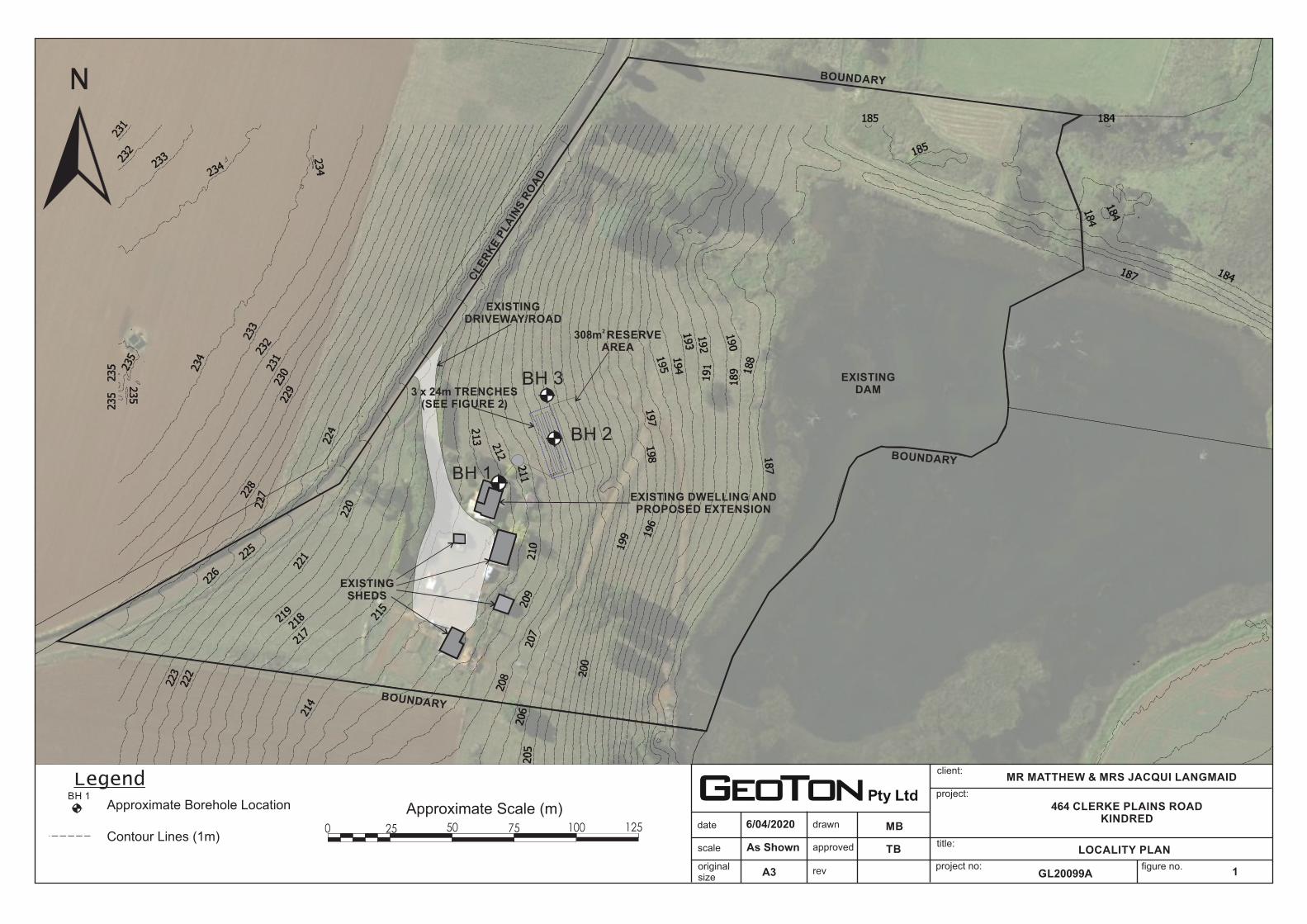
The logs of the boreholes are included in Appendix A and their locations are shown on
Figure 1 attached.
3 SITE CONDITIONS
The site is located on an approximately 5.6ha lot on the lower southern side of Clerke
Plains Road, Kindred. The site comprises partially developed farmland with an existing
farmhouse and four sheds. The ground surface across the site has a moderate easterly
fall towards an existing Tasmanian Irrigation dam and has a low to moderate grass
cover with scattered trees and farm tracks.
The proposed wastewater disposal area is to be located downslope, to the north of the
exiting farmhouse which is to be redeveloped.
Photographs of the site are attached as Plates 1 and 2.

Site Classification & On-site Wastewater Disposal Assessment and Design
Geoton Pty Ltd 2 GL20099Ab 6 April 2020
The Mineral Resources Tasmania (MRT) Digital Geological Atlas, 1:25,000 Series,
shows the site to be located on Cretaceous aged basalt, with this being generally
confirmed by the field data.
Examination of the LIST Landslide Planning Map – Hazard Bands Overlay, indicates
that the upper slopes around the existing farm structures are mapped as being within a
low hazard landslide band, with a small area of medium hazard to the south-east of the
farmhouse.
The investigation indicated that the soil profile was generally uniform over the site. All
boreholes encountered clayey silt topsoil to depths of 0.2m to 0.3m, underlain by high
plasticity clayey silt to the investigated/refusal depths of 1.5m to 2.0m. Borehole BH2
encountered auger refusal at a depth of 1.5m on an inferred cobble.
The boreholes did not encounter any signs of seepage over the investigated depths.
An assessment of the plasticity characteristics of the materials encountered indicates
that the clay soils at this site possess a high shrink/swell potential.
4 SITE CLASSIFICATION
After allowing due consideration of the site geology, drainage and soil conditions, the
site has been classified as follows:
CLASS H1 (AS 2870)
Foundation designs in accordance with this classification are to be subject to the
overriding conditions of Section 5 below.
This Classification is applicable only for ground conditions encountered at the time of
this investigation. If cut or fill earthworks are carried out, then the Site Classification will
need to be re-assessed, and possibly changed.
5 FOUNDATIONS
Particular attention should be paid to the design of footings as required by AS 2870 –
2011.
In addition to normal founding requirements arising from the above classification,
particular conditions at this site dictate that the founding medium for all footings should
be as follows:
Clayey SILT (MH) – high plasticity, red/brown
encountered below 0.3m from the existing ground surface.
An allowable bearing pressure of 100kPa is available for edge beams, strips and pads
founded as above.
The site classification presented assumes that the current natural drainage and
infiltration conditions at the site will not be markedly affected by the proposed site
development work. Care should therefore be taken to ensure that surface water is not
permitted to collect adjacent to the structure and that significant changes to seasonal

Site Classification & On-site Wastewater Disposal Assessment and Design
Geoton Pty Ltd 3 GL20099Ab 6 April 2020
soil moisture equilibria do not develop as a result of service trench construction or tree
root action.
Attention is drawn to Appendix B of AS 2870 and CSIRO Building Technical File BTF18
“Foundation Maintenance and Footing Performance: A Homeowner’s Guide” as a guide to maintenance requirements for the proposed structure.
Although the borehole data provides an indication of subsurface conditions at the site,
variations in soil conditions may occur in areas of the site not specifically covered by
the field investigation. The base of all footing or beam excavations should therefore be
inspected to ensure that the founding medium meets the requirements referenced
herein with respect to type and strength of founding material.
The boreholes were backfilled shortly after being drilled, not allowing time for
groundwater seepage flows to develop. Groundwater seepages or higher groundwater
levels can occur during and/or after a prolonged period of wet weather or a heavy
rainfall event.
6 WIND CLASSIFICATION
After allowing due consideration of the region, terrain, shielding and topography, the
site has been classified as follows:
WIND CLASSIFICATION N3 (AS 4055)
REGION TERRAIN
CATEGORY
SHIELDING TOPOGRAPHY
A TC2 NS T1
7 EFFLUENT DISPOSAL
The AS/NZS 1547:2012 and Building Act 2016 Director’s Guidelines for On-Site
Wastewater Management Systems provide guides for typical wastewater flow
allowances under a range of circumstances. As a general guide, the standard
recommends a typical wastewater flow of 120 litres/person/day for households on
reticulated water. As the dwelling is 3 bedrooms with a study with a population
equivalent of 6, a value of 720L/day has been adopted.
7.1 Permeability of Soil and Soil Category
The soil has been classified as follows:
• Texture – Clay Loams (Table E1 from AS1547-2012);
• Structure – Weakly Structured (Table E4 from AS/NZS1547-2012); and
• Category – 4 (Table E1 from AS/NZS1547:2012).
The permeability (Ksat) at the site was measured at 0.4m/day. For weakly structured
Category 4 soils the indicative Ksat from AS/NZS1547 Table 5.1 is 0.12-0.5m/day.

Site Classification & On-site Wastewater Disposal Assessment and Design
Geoton Pty Ltd 4 GL20099Ab 6 April 2020
Therefore, the measured permeability is consistent with weakly structured Category 4
soils.
• Adopted Permeability – 0.4m/day.
7.2 Disposal and Treatment Method
This site assessment indicates that the site is suitable for the disposal of domestic
effluent by way of a septic tank, which is required to have a minimum capacity of
3500L, and absorption trenches. The soil within the proposed effluent disposal area is
assessed as having sufficient depth and clay content to provide an adequate
attenuation period for the breakdown of pathogens within the treated effluent.
7.3 Design Loading Rate
The adopted design loading rate for the absorption trenches has been set at 10mm/day
as outlined in AS/NZS 1547:2012 Table L1.
7.4 Absorption Trench System
Guidelines for the design of the trench systems are outlined in AS/NZS 1547:2012
Appendix L. The method of determining the dimensions for the trenches is outlined in
AS/NZS 1547:2012 Section L4 and is as follows: L = QDLR × W
Where L = Length in metres
Q = Design daily flow in L/day
DLR = Design Loading Rate in mm/day
W = Trench width in metres (set at 1.0m)
As the DLR value has been set at 10mm/day and the design daily flow (Q) has been
set at 1050L/day, when the parameters are inserted in the above equation the trench
dimensions required are as follows:
• Trench length = 72 (3 x 24m trenches)
• Trench width = 1.0m
• Trench depth = 0.6m
The trenches are to be installed parallel to each other along the contours.
The disposal field for the above scenario would need to be a minimum of 28m long and
11m wide, due to the following conditions:
• A 2m buffer is required around the outside of the disposal field; and
• A downslope separation of 2m (minimum) must be left between trenches.
This would give a disposal area of approximately 308m2. These dimensions may be
modified to suit the client’s needs provided that the total length remains and the spacing between and around the trenches is adhered to.

Site Classification & On-site Wastewater Disposal Assessment and Design
Geoton Pty Ltd 5 GL20099Ab 6 April 2020
It is noted that AS/NZS 1547:2012 recommends that trench lengths be limited to about
20m, however a longer trench is possible provided the installer can guarantee a level
base over the proposed length.
There is adequate secondary (back-up) area of 308m2 if required.
The trenches are to be located in the area shown on the site plan. Distribution boxes
are to be installed to ensure even distribution of effluent to the three trenches.
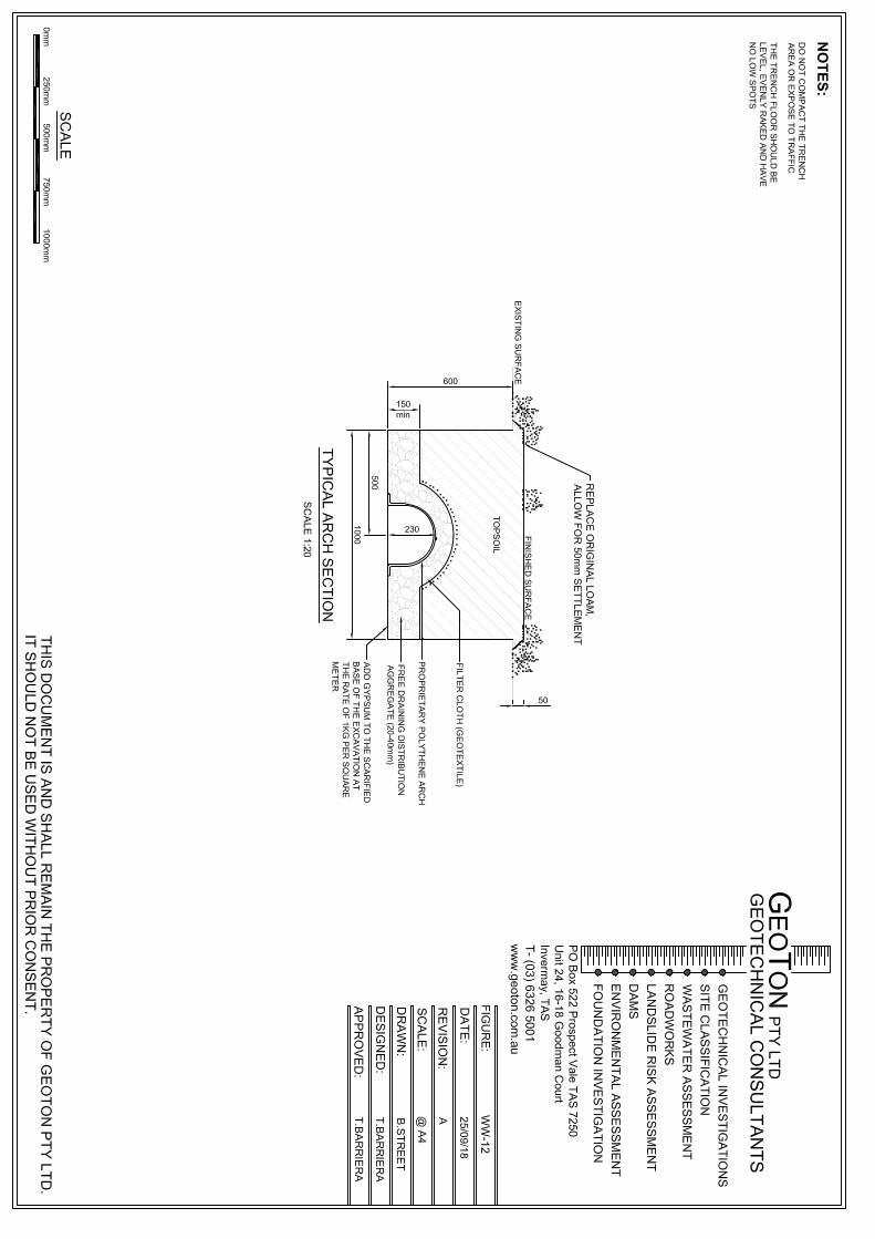
The trenches are to be constructed as per the cross sections located on Figure WW-12
attached. The arch trench is the preferred trench type.
7.5 Setbacks
The minimum separation distance between the disposal area and downslope features
is based on Appendix R from AS/NZS 1547:2012 “Recommended Setback Distances
for Land Application Systems” and Building Act 2016 Director’s Guidelines for On-Site
Wastewater Management Systems. As per Table R1 from AS/NZS 1547:2012 and
Section 3: Standards for Wastewater Land Application Areas the following setbacks are
required:
• A setback of 80m is required from downslope watercourses and sensitive
features including the existing dam on the opposite block;
• A setback of 40.0m is required from downslope property boundaries;
• A setback of 1.5m is required from cross-slope or up-slope property boundaries;
and
• A setback of 1.5m is required for buildings situated cross-slope or up-slope.
7.6 Wastewater Recommendations
It is recommended that the following actions are undertaken in looking after your
system:
• Septic tanks must be pumped out at least every 3 to 5 years or more frequently
depending on usage;
• Minimise domestic water use;
• Minimise the use of non-biodegradable detergents;
• Minimise the use of detergents containing phosphorous (eg calgon and similar);
• Avoid discharging polluting chemicals into wastewater systems; and
• Monitor quality of groundwater.
References:
AS 2870 - 2011 Residential Slabs and Footings Construction
AS 4055 - 2012 Wind Loads for Housing
AS/NZS 1547- 2012 On-site domestic-wastewater management

Site Classification & On-site Wastewater Disposal Assessment and Design
Geoton Pty Ltd 6 GL20099Ab 6 April 2020
Attachments:
Limitations of report
Figure 1 – Locality Plan
Figure 2 – Site Plan
Figure WW-01 – Typical Cut-Off Trench Section
Figure WW-12 – Typical Trench Section
Site Photograph
Appendix A – Borehole Logs & Explanation Sheets
Appendix B – Certificate Forms

Geoton Pty Ltd
Geotechnical Consultants - Limitations of report
These notes have been prepared to assist in the interpretation and understanding of the limitations of
this report.
Project specific criteria
The report has been developed on the basis of
unique project specific requirements as
understood by Geoton and applies only to the site
investigated. Project criteria are typically
identified in the Client brief and the associated
proposal prepared by Geoton and may include
risk factors arising from limitations on scope
imposed by the Client. The report should not be
used without further consultation if significant
changes to the project occur. No responsibility for
problems that might occur due to changed factors
will be accepted without consultation.
Subsurface variations with time
Because a report is based on conditions which
existed at the time of subsurface exploration,
decisions should not be based on a report whose
adequacy may have been affected by time. For
example, water levels can vary with time, fill may
be placed on a site and pollutants may migrate
with time. In the event of significant delays in the
commencement of a project, further advice
should be sought.
Interpretation of factual data
Site assessment identifies actual subsurface
conditions only at those points where samples
are taken and at the time they are taken. All
available data is interpreted by professionals to
provide an opinion about overall site conditions,
their likely impact on the proposed development
and recommended actions. Actual conditions may
differ from those inferred to exist, as it is virtually
impossible to provide a definitive subsurface
profile which includes all the possible variabilities
inherent in soil and rock masses.
Report Recommendations
The report is based on the assumption that the
site conditions as revealed through selective point
sampling are indicative of actual conditions
throughout an area. This assumption cannot be
substantiated until earthworks and/or foundation
construction is almost complete and therefore the
report recommendations can only be regarded as
preliminary. Where variations in conditions are
encountered, further advice should be sought.
Specific purposes
This report should not be applied to any project
other than that originally specified at the time the
report was issued.
Interpretation by others
Geoton will not be responsible for interpretations
of site data or the report findings by others
involved in the design and construction process.
Where any confusion exists, clarification should
be sought from Geoton.
Report integrity
The report as a whole presents the findings of the
site assessment and the report should not be
copied in part or altered in any way.
Geoenvironmental issues
This report does not cover issues of site
contamination unless specifically required to do
so by the client. In the absence of such a
request, Geoton take no responsibility for such
issues.
approved
date
scale title:
project no:
project:
client:
figure no.originalsize
drawn
revA3
LOCALITY PLAN
1
BH 1Approximate Borehole Location
Legend MR MATTHEW & MRS JACQUI LANGMAID
464 CLERKE PLAINS ROADKINDRED
6/04/2020
As Shown
MB
GL20099A
TB
Approximate Scale (m)
7550250 100 125
BH 1
BH 2
BH 3
CLE
RK
E P
LA
INS
RO
AD
N
EXISTING DWELLING AND PROPOSED EXTENSION
BOUNDARY
BOUNDARY
BOUNDARY
EXISTINGDAM
EXISTINGSHEDS
Contour Lines (1m)
3 x 24m TRENCHES(SEE FIGURE 2)
2 308m RESERVE
AREA
EXISTINGDRIVEWAY/ROAD

approved
date
scale title:
project no:
project:
client:
figure no.originalsize
drawn
revA3 2
BH 1
BH 2
DCP 1
DCP 2
DCP 3
DCP 4
DCP 5
BH 3
BH 5
BH 7
BH 9
BH 4
BH 6
BH 8
Approximate Scale (m)
3020100 40
BH 1Approximate Borehole LocationTP 1
TP 4
TP 3
TP 2
TP 1
TP 1
TP 7
TP 5
TP 6
TP 8
Approximate Test Pit Location
Legend
N
Approximate Scale (m)
4010 300 20
N
8060400 20
Approximate Scale (m)BH 1Approximate Borehole Location
Legend
BH 1
BH 3
BH 4
BH 2
TB
O5
Approximate Slope AngleSITE PLAN
MR MATTHEW & MRS JACQUI LANGMAID
464 CLERKE PLAINS ROADKINDRED
6/04/2020
1:200
MB
GL20099A
TB
EXISTING DWELLINGWITH PROPOSED EXTENSION
3500LSEPTICTANK
Contour Lines (1m)
4
3 x 24m LONG1.0m WIDE, 0.6m Deep
TRENCHES
DISTRIBUTION BOX
2308m DISPOSAL AREA
2301m RESERVE AREA
NOTES
PLUMBING CONNECTIONS TO BE CARRIED OUT IN ACCORDANCE WITH PLUMBING CODES AND REGULATIONS
VENTS, OVERFLOW RELIEF GULLY AND INSPECTION OPENINGS TO BE PROVIDED AS PER THE PLUMBING CODES AND REGULATIONS
ABSORPTION TRENCHES ARETO BE SET BACK 80m FROMDOWNHILL SENSITIVE FEATURESSUCH AS WATER COURSES, 40mFROM DOWNHILL PROPERTY BOUNDARIES AND 1.5m UPHILLAND LATERALLY FROM BUILDINGSAND PROPERTY BOUNDARIES
N
2308m RESERVE
AREA
BH 1
BH 2
BH 2
O
O
10 - 12
O
O
10 - 12
Cut-Off Drain(See Figure WW-01)


date:
title:
project no:
project:
client:
figure no.originalsize
A4
PHOTOGRAPH
Plate 1
Plate 1 - Looking south across the proposed wastewater disposal areatoward the existing dwelling
11/03/2020
MR MATTHEW & MRS JACQUI LANGMAID
464 CLERKE PLAINS ROADKINDRED
GL20099A

Appendix A Borehole Logs

ENGINEERINGBOREHOLE LOG
Geotechnical Consultants Borehole no. BH1PO Box 522 Prospect TAS 7250 Sheet no. 1 of 1Unit 24, 16-18 Goodman Court, Invermay TAS Job no. GL20099ATel (03) 6326 5001
Date : 11/03/20Logged By : MG
Slope: 90O RL Surface :Bearing: - Datum :
ML M F/St
0.25
ML M St W<PL
0.50V = 96kPa
0.75
DLL=61%PI=18%LS=12% 1.00
V > 140kPa
1.25
1.50
1.75
2.00V = 70 kPa
2.25
Supp
ort
Pene
tratio
n
Wat
er Notes Samples
Tests
Depth (m)
sand
Clayey SILT - high plasticity, red/brown, with cobbles and fine grained
Client : Mr Matthew & Mrs Jacqui LangmaidProject : Site Classification & On-site Wastewater Assessment & DesignLocation : 464 Clerke Plains Road, Kindred
Gra
phic
log
Cla
ssifi
catio
n Sy
mbo
l
Hole diameter : 150mmDrill model : Drilltech Easting:
Met
hod
Northing:
Structure, additional observations
TOPSOIL - Clayey SILT, low plasticity,red/brown, root fibres
Con
sist
ency
de
nsity
, ind
ex
Moi
stur
e co
nditi
on
Material Description
Borehole BH1 terminated @ 2.0m
ADV
N

ENGINEERINGBOREHOLE LOG
Geotechnical Consultants Borehole no. BH2PO Box 522 Prospect TAS 7250 Sheet no. 1 of 1Unit 24, 16-18 Goodman Court, Invermay TAS Job no. GL20099ATel (03) 6326 5001
Date : 11/03/20Logged By : MG
Slope: 90O RL Surface :Bearing: - Datum :
ML M St
0.25 ML M VSt W<PL
0.50
0.75
1.00
1.25
1.50
1.75
2.00
2.25
Client : Mr Matthew & Mrs Jacqui LangmaidProject : Site Classification & On-site Wastewater Assessment & DesignLocation : 464 Clerke Plains Road, Kindred
Met
hod
Supp
ort
Pene
tratio
n
Wat
er Notes Samples
Tests
Drill model : Drilltech Easting:Hole diameter : 150mm Northing:
Con
sist
ency
de
nsity
, ind
ex
Structure, additional observations
TOPSOIL - Clayey SILT, low plasticity,red/brown, root fibres
Depth (m)
Gra
phic
log
Cla
ssifi
catio
n Sy
mbo
lMaterial Description
Moi
stur
e co
nditi
on
Clayey SILT - high plasticity, red/brown, with cobbles and fine grainedsand
Borehole BH2 refusal @ 1.5m on inferred cobble
ADV
N

ENGINEERINGBOREHOLE LOG
Geotechnical Consultants Borehole no. BH3PO Box 522 Prospect TAS 7250 Sheet no. 1 of 1Unit 24, 16-18 Goodman Court, Invermay TAS Job no. GL20099ATel (03) 6326 5001
Date : 11/03/20Logged By : MG
Slope: 90O RL Surface :Bearing: - Datum :
ML M L/St
0.25 ML M VSt W < Wp
0.50
0.75
1.00
1.25
W≈Wp W<WL
1.50
1.75
2.00
2.25
Location : 464 Clerke Plains Road, KindredDrill model : Drilltech Easting:
Client : Mr Matthew & Mrs Jacqui LangmaidProject : Site Classification & On-site Wastewater Assessment & Design
Hole diameter : 150mm Northing:
Met
hod
Supp
ort
Pene
tratio
n
Wat
er Notes Samples
Tests
Depth (m)
Gra
phic
log
Cla
ssifi
catio
n Sy
mbo
lMaterial Description
Clayey SILT - high plasticity, red/brown, with cobbles
Moi
stur
e co
nditi
on
Con
sist
ency
de
nsity
, ind
ex
Structure, additional observations
TOPSOIL - Clayey SILT, low plasticity,red/brown, root fibres
ADV
N
Borehole BH3 terminated @ 2.0m
Becoming orange/red

Investigation Log Explanation Sheet
METHOD – BOREHOLE
TERM Description
AS Auger Screwing*
AD Auger Drilling*
RR Roller / Tricone
W Washbore
CT Cable Tool
HA Hand Auger
DT Diatube
B Blank Bit
V V Bit
T TC Bit
* Bit shown by suffix e.g. ADT
METHOD – EXCAVATION
TERM Description
N Natural exposure
X Existing excavation
H Backhoe bucket
B Bulldozer blade
R Ripper
E Excavator
SUPPORT
TERM Description
M Mud
N Nil
C Casing
S Shoring
PENETRATION
1 2 3 4
No resistance ranging to Refusal
WATER
Symbol Description
Water inflow
Water outflow
17/3/08 water on date shown
NOTES, SAMPLES, TESTS
TERM Description
U50 Undisturbed sample 50 mm diameter
U63 Undisturbed sample 63 mm diameter
D Disturbed sample
N Standard Penetration Test (SPT)
N* SPT – sample recovered
NC SPT with solid cone
V Vane Shear
PP Pocket Penetrometer
P Pressumeter
BS Bulk sample
E Environmental Sample
R Refusal
DCP Dynamic Cone Penetrometer (blows/100mm)
PL Plastic Limit
LL Liquid Limit
LS Linear Shrinkage
CLASSIFICATION SYMBOLS AND SOIL
DESCRIPTION
Based on AS 1726:2017
MOISTURE
TERM Description
D Dry
M Moist
W Wet
CONSISTENCY/DENSITY INDEX
TERM Description
VS very soft
S soft
F firm
St stiff
VSt very stiff
H hard
Fr friable
VL very loose
L loose
MD medium dense
D dense
VD Very dense

Soil Description Explanation Sheet (1of 2)
DEFINITION
In engineering terms, soil includes every type of uncemented or
partially cemented inorganic or organic material found in the
ground. In practice, if the material can be remoulded or
disintegrated by hand in its field condition or in water it is
described as a soil. Other materials are described using rock
description terms.
CLASSIFICATION SYMBOL AND SOIL NAME
Soils are described in accordance with the AS 1726: 2017 as
shown in the table on Sheet 2.
PARTICLE SIZE DEFINITIONS
NAME SUBDIVISION SIZE (mm)
BOULDERS >200
COBBLES 63 to 200
GRAVEL
Coarse 19 to 63
Medium 6.7 to 19
Fine 2.36 to 6.7
SAND
Coarse 0.6 to 2.36
Medium 0.21 to 0.6
Fine 0.075 to 0.21
SILT 0.002 to 0.075
CLAY <0.002
MOISTURE CONDITION
Coarse Grained Soils
Dry Non-cohesive and free running.
Moist Soil feels cool, darkened in colour.
Soil tends to stick together.
Wet As for moist but with free water forming when
handling.
Fine Grained Soils
Moist, dry of Plastic Limited – w < PL
Hard and friable or powdery.
Moist, near Plastic Limit – w ≈ PL
Soils can be moulded at a moisture content
approximately equal to the plastic limit.
Moist, wet of Plastic Limit – w > PL
Soils usually weakened and free water forms on
hands when handling.
Wet, near Liquid Limit - w ≈ LL
Wet, wet of Liquid Limit - w > LL
CONSISTENCY TERMS FOR COHESIVE SOILS
TERM
UNDRAINED
STRENGTH
su (kPa)
FIELD GUIDE
Very Soft ≤12 Exudes between the fingers when
squeezed in hand
Soft 12 to 25 Can be moulded by light finger
pressure
Firm 25 to 50 Can be moulded by strong finger
pressure
Stiff 50 to 100 Cannot be moulded by fingers
Very Stiff 100 to 200 Can be indented by thumb nail
Hard >200 Can be indented with difficulty by
thumb nail
Friable – Can be easily crumbled or broken
into small pieces by hand
RELATIVE DENSITY OF NON-COHESIVE SOILS
TERM DENSITY INDEX (%)
Very Loose ≤15
Loose 15 to 35
Medium Dense 35 to 65
Dense 65 to 85
Very Dense > 85
DESCRIPTIVE TERMS FOR ACCESSORY SOIL
COMPONENTS
DE
SIG
NA
TIO
N
OF
CO
MP
ON
EN
T IN COARSE
GRAINED
SOILS
IN FINE
GRAINED
SOILS
TERM
% Fines
% Accessory
coarse
fraction
% Sand/
gravel
Minor ≤5 ≤15 ≤15 Trace
>5, ≤12 >15, ≤30 >15, ≤30 With
Secondary >12 >30 >30 Prefix
SOIL STRUCTURE
ZONING CEMENTING
Layer Continuous across
the exposure or
sample.
Weakly
cemented
Easily
disaggregated
by hand in air
or water. Lens Discontinuous layer
of different material,
with lenticular shape. Moderately
cemented
Effort is
required to
disaggregate
the soil by
hand in air or
water.
Pocket An irregular inclusion
of different material.
GEOLOGICAL ORIGIN
WEATHERED IN PLACE SOILS
Extremely
weathered
material
Structure and/or fabric of parent rock
material retained and visible.
Residual soil Structure and/or fabric of parent rock
material not retained and visible.
TRANSPORTED SOILS
Aeolian soil Carried and deposited by wind.
Alluvial soil Deposited by streams and rivers.
Colluvial soil Soil and rock debris transported downslope
by gravity.
Estuarine soil Deposited in coastal estuaries, and
including sediments carried by inflowing
rivers and streams, and tidal currents.
Fill Man-made deposit. Fill may be significantly
more variable between tested locations
than naturally occurring soils.
Lacustrine soil Deposited in freshwater lakes.
Marine soil Deposited in a marine environment.

Soil Description Explanation Sheet (2 of 2)
SOIL CLASSIFICATION INCLUDING IDENTIFICATION AND DESCRIPTION
FIELD IDENTIFICATION PROCEDURES
(Excluding particles larger than 63 mm and basing fractions on estimated mass)
GROUP
SYMBOL PRIMARY NAME
CO
AR
SE
GR
AIN
ED
SO
IL
More
tha
n 6
5%
of
soil
exclu
din
g o
ve
rsiz
e
fraction
is la
rger
tha
n 0
.075 m
m
(A 0
.07
5 m
m p
art
icle
is a
bo
ut th
e s
malle
st p
art
icle
vis
ible
to n
aked
eyes)
GR
AV
EL
More
tha
n h
alf o
f
coars
e f
ractio
n is
larg
er
tha
n 2
.36 m
m
CLE
AN
GR
AV
EL
(Little o
r
no fin
es) Wide range in grain size and substantial
amounts of all intermediate particle sizes GW GRAVEL
Predominantly one size or a range of sizes
with some intermediate sizes missing GP GRAVEL
GR
AV
EL
WIT
H F
INE
S
(App
recia
ble
am
oun
t
of fin
es)
Non-plastic fines (for identification procedures
see ML and MH below) GM Silty GRAVEL
Plastic fines (for identification procedures see
CL, CI and CH below) GC Clayey GRAVEL
SA
ND
More
tha
n h
alf o
f
coars
e f
ractio
n is
sm
alle
r th
an 2
.36 m
m
CLE
AN
SA
ND
(Little o
r
no fin
es) Wide range in grain size and substantial
amounts of all intermediate sizes SW SAND
Predominantly one size or a range of sizes
with some intermediate sizes missing SP SAND
SA
ND
WIT
H F
INE
S
(App
recia
ble
am
oun
t
of fin
es)
Non-plastic fines (for identification procedures
see ML and MH below) SM Silty SAND
Plastic fines (for identification procedures see
CL, CI and CH below) SC Clayey SAND
FIN
E G
RA
INE
D S
OIL
More
tha
n 3
5%
of
soil
exclu
din
g o
ve
rsiz
e
fraction
is s
malle
r th
an 0
.07
5 m
m
IDENTIFICATION PROCEDURES ON FRACTIONS <0.075 mm
DRY STRENGTH DILATANCY TOUGHNESS
SIL
T &
CLA
Y
(low
to
mediu
m
pla
sticity,
LL ≤
50
) None to Low Slow to Rapid Low ML SILT
Medium to High None to Slow Medium CL, CI CLAY
Low to Medium Slow Low OL ORGANIC SILT
SIL
T &
CLA
Y
(hig
h
pla
sticity,
LL >
50
) Low to Medium None to Slow Low to Medium MH SILT
High to Very High None High CH CLAY
Medium to High None to Very Slow Low to Medium OH ORGANIC CLAY
Highly Organic
Soil
Readily identified by colour, odour, spongy feel and frequently by
fibrous texture. Pt PEAT
● LL – Liquid Limit.
COMMON DEFECTS IN SOILS
TERM DEFINITION DIAGRAM TERM DEFINITION DIAGRAM
PARTING A surface or crack across which the
soil has little or no tensile strength.
Parallel or sub parallel to layering
(e.g. bedding). May be open or
closed.
SOFTENED
ZONE
A zone in clayey soil, usually adjacent to a defect in which the soil has a higher moisture content than elsewhere.
FISSURE A surface or crack across which the
soil has little or no tensile strength,
but which is not parallel or sub
parallel to layering. May be open or
closed. May include desiccation
cracks.
TUBE Tubular cavity. May occur singly or
as one of a large number of
separate or inter-connected tubes.
Walls often coated with clay or
strengthened by denser packing of
grains. May contain organic matter.
SHEARED
SEAM
Zone in clayey soil with roughly
parallel near planar, curved or
undulating boundaries containing
closely spaced, smooth or
slickensided, curved intersecting
fissures which divide the mass into
lenticular or wedge-shaped blocks.
TUBE
CAST
An infilled tube. The infill may be uncemented or weakly cemented soil or have rock properties.
SHEARED
SURFACE
A near planar curved or undulating, smooth, polished or slickensided surface in clayey soil. The polished or slickensided surface indicates that movement (in many cases very little) has occurred along the defect.
INFILLED
SEAM
Sheet or wall like body of soil
substance or mass with roughly
planar to irregular near parallel
boundaries which cuts through a
soil mass. Formed by infilling of
open defects.

Appendix B Certificate Forms

Director of Building Control – Date Approved 1 July 2017 Building Act 2016 - Approved Form No. 55
CERTIFICATE OF QUALIFIED PERSON – ASSESSABLE ITEM
Section 321
To: Mr Matthew & Mrs Jacqui Langmaid Owner /Agent
464 Clerke Plains Road Address
Kindred, Tas 7310 Suburb/postcode
Qualified person details:
Qualified person: Tony Barriera - Geoton Pty. Ltd.
Address: PO Box 522 Phone No: 03 6326 5001
Prospect Tas 7250 Fax No:
Licence No: CC6220 P Email address: [email protected]
Qualifications and Insurance details:
Tony Barriera – BEng, MSc (description from Column 3 of the Director's Determination - Certificates by Qualified Persons for Assessable Items CPEng, NER – IEAust 471929
Civil, Geotechnical Certain Underwriters at Lloyd's- N17000416
Speciality area of expertise:
Geotechnical Engineering (description from Column 4 of the Director's Determination - Certificates by Qualified Persons for Assessable Items)
Details of work:
Address: 464 Clerke Plains Road Lot No: 1
Kindred, Tas 7310 Certificate of title No: 110463/1
The assessable item related to this certificate:
Classification of foundation conditions according to AS2870 - 2011
(description of the assessable item being certified) Assessable item includes – - a material; - a design - a form of construction - a document - testing of a component, building
system or plumbing system - an inspection, or assessment,
performed
Certificate details:
Certificate type: Foundation Site Classification – (description from Column 1 of Schedule 1 of the Director's Determination - Certificates by Qualified Persons for Assessable Items n) AS2870
This certificate is in relation to the above assessable item, at any stage, as part of - (tick one)
building work, plumbing work or plumbing installation or demolition work:
or
a building, temporary structure or plumbing installation: X
Form 55

Director of Building Control – Date Approved 1 July 2017 Building Act 2016 - Approved Form No. 55
In issuing this certificate the following matters are relevant –
Documents: Geoton Pty Ltd, Report Reference No. GL20099Ab, dated 6/04/2020
Relevant Refer to report calculations:
References: AS 2870 – 2011 Residential Slabs and Footings Construction AS 4055 – 2012 Wind Loads for Housing
CSIRO Building Technical File 18
Substance of Certificate: (what it is that is being certified)
Site Classification in accordance to AS2870 - 2011 Wind Loading in accordance to AS 4055 - 2012 Findings and recommendations of report
Scope and/or Limitations
The classification applies to the site as investigated at the time and does not account for any future alteration to foundation conditions resulting from earthworks, drainage condition changes or site maintenance variations.
I certify the matters described in this certificate.
Signed: Certificate No: Date:
Qualified person:
GL20099Ab
6/04/2020

Director of Building Control - date approved: 2 August 2017 Building Act 2016 - Approved Form No 35
CERTIFICATE OF THE RESPONSIBLE DESIGNER
Section 94 Section 106 Section 129 Section 155
To: Mr Matthew & Mrs Jacqui Langmaid Owner name
464 Clerke Plains Road Address
KINDRED TAS 7310 Suburb/postcode
Designer details:
Name: Tony Barriera
Category: Civil Engineer Hydraulic - Domestic
Business name: Geoton Pty Ltd Phone No: 03 6326 5001
Business address:
P O Box 522
Prospect TAS 7250 Fax No:
Licence No: IEAust 471929, CC6220 P
Email address: [email protected]
Details of the proposed work:
Owner/Applicant Mr Matthew & Mrs Jacqui Langmaid Designer’s project reference No. GL20099Ab
Address: 464 Clerke Plains Road Lot No: 110463/1
KINDRED TAS 7310
(X all applicable)
Description of work:
Type of work: Building work Plumbing work X
New building on-site wastewater management system
(new building / alteration / addition / repair / removal / re-erection water / sewerage / stormwater / on-site wastewater management system / backflow prevention / other)
Description of the Design Work (Scope, limitations or exclusions): (X all applicable certificates)
Certificate Type: Certificate Responsible Practitioner
Building design Architect or Building Designer
Structural design Engineer or Civil Designer
Fire Safety design Fire Engineer
Civil design Civil Engineer or Civil Designer
Hydraulic design Building Services Designer
Fire service design Building Services Designer
Electrical design Building Services Designer
Mechanical design Building Service Designer
Plumbing design Plumber-Certifier; Architect, Building Designer or Engineer
Other (specify)
Deemed-to-Satisfy: Performance Solution: (X the appropriate box)
Other details:
All design documents provided in Report GL20099Ab, dated 6/04/2020
Form 35

Director of Building Control - date approved: 2 August 2017 Building Act 2016 - Approved Form No 35
Design documents provided:
The following documents are provided with this Certificate – Document description:
Drawing numbers: Prepared by: Date:
Schedules: Prepared by: Date:
Specifications: Prepared by: Date:
Computations: Prepared by: Date:
Performance solution proposals: Prepared by: Date:
Test reports: Prepared by: Date:
Standards, codes or guidelines relied on in design process:
All design documents are contained within report
AS/NZS1547:2012 On-site domestic-wastewater management
Any other relevant documentation:
Attribution as designer:
I Tony Barriera of Geoton Pty Ltd am responsible for the design of that part of the work as described in this certificate;
The documentation relating to the design includes sufficient information for the assessment of the work in accordance with the Building Act 2016 and sufficient detail for the builder or plumber to carry out the work in accordance with the documents and the Act;
This certificate confirms compliance and is evidence of suitability of this design with the requirements of the National Construction Code.
Name: (print) Signed Date
Designer: Tony Barriera
6/04/2020
Licence No: CC6220P

Director of Building Control - date approved: 2 August 2017 Building Act 2016 - Approved Form No 35
`
Assessment of Certifiable Works: (TasWater)
Note: single residential dwellings and outbuildings on a lot with an existing sewer connection are not considered to increase demand and are not certifiable.
If you cannot check ALL of these boxes, LEAVE THIS SECTION BLANK.
TasWater must then be contacted to determine if the proposed works are Certifiable Works.
I confirm that the proposed works are not Certifiable Works, in accordance with the Guidelines for TasWater CCW Assessments, by virtue that all of the following are satisfied:
The works will not increase the demand for water supplied by TasWater
The works will not increase or decrease the amount of sewage or toxins that is to be removed by,
or discharged into, TasWater’s sewerage infrastructure
The works will not require a new connection, or a modification to an existing connection, to be
made to TasWater’s infrastructure
The works will not damage or interfere with TasWater’s works
The works will not adversely affect TasWater’s operations
The work are not within 2m of TasWater’s infrastructure and are outside any TasWater easement
I have checked the LISTMap to confirm the location of TasWater infrastructure
If the property is connected to TasWater’s water system, a water meter is in place, or has been applied for to TasWater.
Certification:
I Tony Barriera of Geoton Pty Ltd being responsible for the proposed work, am satisfied that the works
described above are not Certifiable Works, as defined within the Water and Sewerage Industry Act 2008,
that I have answered the above questions with all due diligence and have read and understood the
Guidelines for TasWater CCW Assessments.
Note: the Guidelines for TasWater Certification of Certifiable Works Assessments are available at: www.taswater.com.au
Name: (print) Signed Date
Designer: Tony Barriera
6/04/2020
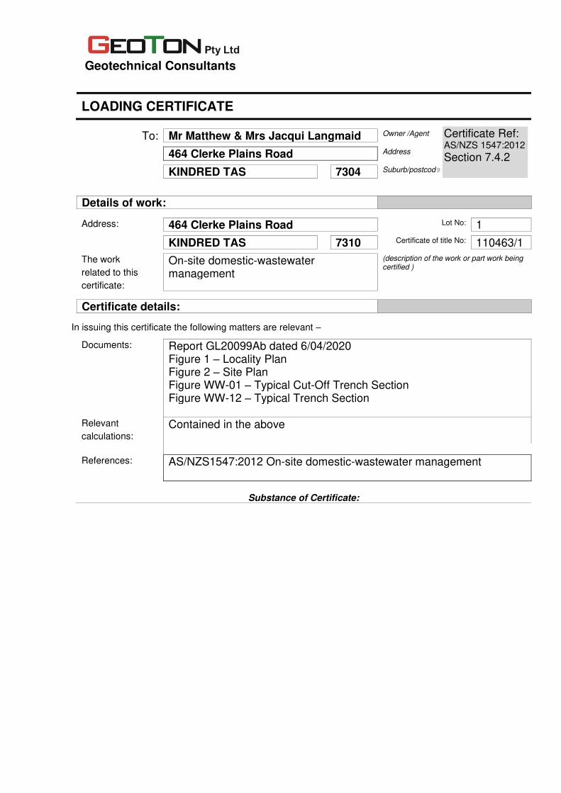
Geotechnical Consultants
LOADING CERTIFICATE
To: Mr Matthew & Mrs Jacqui Langmaid Owner /Agent
464 Clerke Plains Road Address
KINDRED TAS 7304 Suburb/postcode
Details of work:
Address: 464 Clerke Plains Road Lot No: 1
KINDRED TAS 7310 Certificate of title No: 110463/1
The work On-site domestic-wastewater (description of the work or part work being certified )
related to this management certificate:
Certificate details:
In issuing this certificate the following matters are relevant –
Documents: Report GL20099Ab dated 6/04/2020 Figure 1 – Locality Plan Figure 2 – Site Plan Figure WW-01 – Typical Cut-Off Trench Section Figure WW-12 – Typical Trench Section
Relevant Contained in the above calculations:
References: AS/NZS1547:2012 On-site domestic-wastewater management
Substance of Certificate:
Certificate Ref: AS/NZS 1547:2012 Section 7.4.2

This certificate sets out the design criteria and the limitations associated with use of the system. Wastewater Characteristics Population equivalent used for this assessment = 6 (4 Bedrooms) Wastewater volume (L/day) used for this assessment = 720 (120 Litres per person) Approximate blackwater volume (L/day) = 288 Approximate greywater volume (L/day) = 432 Soil Characteristics/Design Criteria Texture (Table E4 from AS/NZS 1547) = Clayey Silt Soil category (Table E1 from AS/NZS 1547) = 4 Soil structure (Table E4 from AS/NZS 1547) = Weakely Structured Indicative permeability (Table 5.1 from AS/NZS 1547) = 0.12m/day – 0.5m/day Adopted permeability = 0.4m/day Adopted Design Loading Rate = 10mm/day Soil thickness for disposal = >2.0m Minimum depth (m) to water = >2.0m Dimensions for On-Site Treatment System Disposal and treatment methods = Septic tank Site modification and specific design = N/A Primary disposal area required = 308m2 Reserve disposal area required = 308m2
Location and use of Reserve area = Reserve area located to the northeast of the existing dwelling. Is there sufficient area available on site for disposal (including reserve) = Yes Notes The purpose of the reserve area is to allow for future extension of the land application system to allow a factor of safety against unforseen malfunction or failure, perhaps following increased household occupancy or inadvertent misuse of the system.
The land application area may be reduced to account for flow reductions by water-saving devices, provided the organic loading rate is not higher than it would have been without the flow reduction.
Allowable Variation from Design Flow Based on a septic tank capacity of 3500L and wastewater design volume of 720L/day the allowable variation from design flow (peak loading events) would be an additional 680L/day (Total flow of 1400L/day as per table J1 of AS/NZS 1547:2012). System Limitations Consequences of overloading the system: Overloading the system can result in failure of the septic tank and land application system. This is a serious health and environmental hazard and can lead to any one or more of the following: Spread of infectious disease; Breeding of mosquitoes and attraction of flies and rodents; Nuisance and unpleasantness; Pollution of waterways; Contamination of bores, wells and groundwater; and alteration to local ecology.

Consequences of under loading the system: Under loading the system may result in the bacteria to stop working and system failure. Operation Requirements Refer to Section T5.2.1 of AS/NZS 1547:2012 for additional requirements. For on-site system to work well the following is required:
• Reduce sludge building up through scraping all dishes to remove fats/grease; don’t use a food waste disposal unit; and don’t put sanitary napkins into the system.
• To keep bacteria working in the septic tank use biodegradable soaps; use a low phosphorous detergent; don’t use powerful bleaches and disinfectants; and don’t put chemicals or paint down the drain.
• Conservation of water will reduce the volume of effluent requiring disposal to the land application area, make it last longer and improve its performance.
Maintenance Requirements Refer to Section T5.2.2 of AS/NZS 1547:2012 for additional requirements. Maintenance of the system should include the following:
• Septic tanks must be inspected at least annually and pumped out regularly once the scum and sludge occupy two thirds of the tank volume. Typically a septic tank must be pumped out at least every 3 to 5 years or more frequently depending on usage.
• Grease traps must be inspected at least quarterly and cleaned out regularly.
• Deep rooting trees or shrubs should not be grown over absorption trenches or pipes.
• Surface water diversion drains should be maintained upslope of and around the land application area and kept clean to reduce seepage of rainwater into the trenches.
• Maintain disposal area by maintaining plants and mowing grass to ensure that plants/grasses take up nutrients with maximum efficiency.
• Check disposal area for blockages such as wet spots and uneven grass colour.
I certify the matters described in this certificate.
Signed: Date: Certificate No.
Certifier:
6/04/2020 GL20099Ab

ABN 12 206 730 093 Shop 29 York Town Square
Launceston Tas 7250 Phone: (03) 6334 1033
E: [email protected] Web: www.akconsultants.com.au
Report for: Matthew & Jacqui Langmaid
Property Location: 464 Clerke Plains Road, Kindred (CT 110463/1)
Prepared by: Astrid Ketelaar and Michael Tempest
AK Consultants 29 York Town Square LAUNCESTON, TAS 7250
Date: 11th March 2020
Agricultural Report

Agricultural Report 2 AK Consultants
SUMMARY
Client:
Matthew & Jacqui Langmaid
Title identification:
CT 110463/1 (29.1ha), 464 Clerke Plains Road, Kindred in the name of P & A Langmaid Rural Resource Zone (Central Coast Interim Planning Scheme 2013).
Proposal: Proposed extension of a dwelling by greater than 30% of existing floor area.
Purpose: To assess the agricultural and primary industry aspects of the proposal.
Land Capability: Published Land Capability at 1:100 000 Class 2 (22.9ha), Class 4 (2.4ha) & Class 5 (3.8ha).
Assessment comments:
All relevant information available at desktop level was considered. A site assessment was not
considered necessary as the imagery is good and the desktop information correlates with the
proponents’ information. This report summarises the findings of the desktop assessment.
Conclusion:
The subject title is 29.1ha and is farmed in conjunction with a 41.1ha title to the south. The land is primarily utilised for irrigated agriculture and there is an existing dwelling in the east of the subject title that is required as part of the existing land use. The existing dwelling and proposed extension are within an area of Class 5 Land Capability that is utilised for pasture. The proposed extension is contained within the existing curtilage that has been converted to domestic use. The loss of this land is therefore considered insignificant in this context. The proposed setbacks to all boundaries are considered to be sufficient to minimise the risk of further constraining or interfering with existing and potential agricultural or primary industry use in the vicinity and follow the precedence of existing dwellings in proximity to boundaries where there is adjacent irrigated cropping activity. It is highly unlikely that the proposed extension on this title will increase the risk of constraining or interfering with agricultural and primary industry any more than occurs from the existing dwelling on this title and existing dwellings in the vicinity. Although the title is within an Irrigation District, the location of the existing dwelling and proposed extension is within an area with Land Capability limitations that has not historically been subject to irrigation, and it is not likely to benefit from irrigation development.
Assessment by:
___________________ Astrid Ketelaar, Natural Resource Management Consultant, Member, Agricultural Institute Australia (current)
and
________________ Michael Tempest, Natural Resource Management Consultant

Agricultural Report 3 AK Consultants
INTRODUCTION
The subject title (CT 110463/1) is located at 464 Clerke Plains Road, Kindred. This title and all surrounding land is zoned as ‘Rural Resource’ under the Central Coast Interim Planning Scheme 2013 (the Planning Scheme). The proponent seeks to gain discretionary approval to extend an existing dwelling on the title by greater than 30% of the existing floor area. The relevant sections of the Planning Scheme are as follows: 26.0 Rural Resource Zone 26.4.3 Location of development for sensitive uses Objective The location of development for sensitive uses on rural land does not unreasonably interfere with or otherwise constrain –
(a) agricultural land for existing and potential sustainable agricultural use dependent on the soil as a growth medium;
(b) agricultural use of land in a proclaimed irrigation district under Part 9 Water Management Act 1999 or land that may benefit from the application of broad-scale irrigation development;
(c) use of land for agricultural production that is not dependent on the soil as a growth medium, including aquaculture, controlled environment agriculture, and intensive animal husbandry;
(d) conservation management; (e) extractive industry; (f) forestry; and (g) transport and utility infrastructure
Performance Criteria: P1 New development, except for extensions to existing sensitive use where the extension is no greater than 30% of the existing gross floor area of the sensitive use, must minimise –
(a) permanent loss of land for existing and potential primary industry use; (b) likely constraint or interference to existing and potential primary industry use on the site
and on adjacent land; (c) permanent loss of land within a proclaimed irrigation district under Part 9 Water
Management Act 1999 or land that may benefit from the application of broad-scale irrigation development; and
(d) adverse effect on the operability and safety of a major road, a railway or a utility All relevant information available at desktop level was considered. A site assessment was not considered necessary as the imagery is good and the desktop information correlates with the proponents’ information. This report assesses the agricultural and primary industry aspects of the
proposal and summarises the findings of the desktop assessment.

Agricultural Report 4 AK Consultants
DESCRIPTION
The title is 29.1ha in area and is situated around a crest at 230m above sea level (ASL). The eastern portion of the title has an easterly aspect and the western portion of the title has a westerly aspect. Both the eastern and western title boundaries sit at approximately 190m ASL. The west of the title is intersected by Jones Road and the east of the title is intersected by Clerke Plains Road. The title has an existing dwelling in the east of the title, which is required as part of the existing use, and the title is farmed in conjunction with a 41.1ha title to the south. Published Land Capability mapping at 1:100 000 scale shows the majority of the land to be Class 2. Class 2 land is defined on The LIST as; land suited to a wide range of intensive cropping and grazing activities with slight limitations to use. Class 2 land is Prime Agricultural Land as defined under the Protection of Agricultural Land Policy 2009 (PAL Policy). There is also approximately 2.4ha of land mapped as Class 4 along the eastern and western boundaries of the title, and 3.8ha of Class 5 land through the east of the title. Class 4 land is described as land well suited to grazing, but which is limited to occasional cropping or a very restricted range of crops, and Class 5 land is described as land unsuited to cropping and with slight to moderate limitations to pastoral use. See Appendix 2 for full Land Capability Class descriptions. There is no published soil mapping available for the site. Mapped underlying geology indicates that the majority of the title is Paleogene - Neogene basalt and related rocks (Tb), described as basalt. The eastern and western portions of the title associated with the drainage lines are mapped as Holocene alluvial, lacustrine and littoral deposit (Qha), which is described as stream alluvium, swamp and marsh deposits. The closest mining lease is for stone and is located approximately 1.8km away to the north west on geology mapped as Tyennan Group and correlates, which is described as dominantly quartzite. The title is primarily mapped by TASVEG 3.0 as agricultural land (FAG), with 1.2ha mapped as water (OAQ) and 0.2ha in the north east of the title is mapped as weed infestation (FWU). The title does not contain any threatened vegetation communities listed under the Nature Conservation Act 2002 or any areas listed as Priority Habitat under the Planning Scheme. There are no records of any threatened flora or fauna species associated with the title (the LIST). An area across the eastern portion of the property is mapped as a landslip hazard under the Planning Scheme. 0.5ha is mapped as ‘medium’ risk and 2.7ha is mapped as ‘low’ risk. These hazard areas are primarily aligned with the Class 5 land. The title is situated within the Forth-Wilmot catchment and the Kindred North Motton Irrigation District. Claytons Rivulet flows along the eastern boundary and an unnamed tributary of Claytons Rivulet originates in the west of the title. Both watercourses contain existing dams and there is a water licence (#1830 in the name of PD & AR Langmaid Pty Ltd) associated with these, with both summer and winter allocations. The dam on Claytons Rivulet encroaches on and is shared with three neighbouring titles, including the title to the south, which is farmed in conjunction with the subject title. PD & AR Langmaid Pty Ltd also hold Irrigation Rights for summer water from the Kindred North Motton Tasmanian Irrigation Scheme. Surrounding titles vary in size. To the northwest and north are a 10.7ha and 15.9ha title under the same ownership which are managed as irrigated agriculture and there is an existing dwelling in the

Agricultural Report 5 AK Consultants
north east of the smaller title. Adjacent to the north west is a 7.8ha title with an existing dwelling in the north west of the title. To the east, across Claytons Rivulet, are two titles (23ha and 73.3ha) managed as agriculture which are each farmed in conjunction with additional titles to the east. Both titles have an existing dwelling. To the south is the 41.1ha title farmed in conjunction with the subject title. Clerke Plains Road forms the majority of their shared boundary. Adjacent to the south west is a 39.8ha title with an existing dwelling in the east and to the west is a 12.6ha title that is under the same ownership as land to the north. Land in proximity to the dwelling is predominantly used for irrigated cropping. The nearest cropping is on the proponent’s land 40m to the west of the dwelling and 50m to the north west of the dwelling. The area that is cropped 40m to the west of the dwelling is approximately 0.3ha, with the more extensive cropping areas a minimum of 50m distance from the dwelling. The nearest cropping on neighbouring land is 185m to the north west.
DISCUSSION
The existing dwelling on the title is required as part of the existing use of the title. The site of the existing dwelling is surrounded by three sheds and landscaped gardens, including a tree hedge that would act as a buffer between the house and Clerke Plains Road and the more extensive irrigated agriculture to the west on the same title. The proposal (as indicated in the site plan by Lachlan Walsh Design 18/12/2019) is to extend the existing dwelling to the north and to the west, in order to align the entire western façade with the existing western extent of the dwelling. There is also a deck extension along the east of the house, however this does not extend further than the existing deck on the eastern side of the dwelling. Overall, the proposed extension extends the existing footprint of the dwelling by approximately 5m to the north. This is contained within the existing curtilage of the domestic garden and is outside of all current and historical productive agricultural areas on the property. Land to the north and east of the dwelling is currently and historically (as indicated by Google imagery 2003-2018) utilised as pasture. While the proposed extension is not expected to impact on the existing or potential primary industry use of the subject title, the potential for the extension to constrain agriculture or primary industry in the vicinity also needs to be considered. The Rural Resource zone requires a 200m setback from adjacent titles. As the proposed extension does not impact the setback distance to the adjacent titles to the east, south, or west, consideration only needs to be given to the setback from the adjacent titles to the north and north east. There are a range of activities associated with grazing and cropping. Learmonth et al. (2007) detail the common range of issues associated with sensitive uses such as residential use in the Rural Resource Zone which can constrain agricultural and primary industry activities (see Appendix 3). Common conflict issues associated with residential use in the Rural Resource zone include spray drift from chemicals which would include fungicide, herbicide, and insecticide, noise from equipment (irrigation equipment, tractors, harvesters, aircraft etc. including during the night and early morning), irrigation water spray drift (generally not potable water), odour from fertilisers and chemicals, and dust during harvesting and ground preparation. The Western Australia Department of Health (DOH, 2012) has published guidelines relating specifically to minimising conflict between agricultural/primary industry activities and residential areas through management of buffer areas. This study particularly focuses on spray drift and dust

Agricultural Report 6 AK Consultants
generation and recommends a minimum separation of 300m to reduce the impact of spray drift, dust, smoke and ash. Through the establishment of an adequately designed, implemented and maintained vegetative buffer, this minimum separation distance can be reduced to 40m. The proposed extension is setback 202m from the adjacent north eastern title across Claytons Rivulet. The setback from the proposed extension to the adjacent titles to the north and north east is approximately 168m and 172m, respectively. In both instances, there is an existing dwelling setback approximately 38m and 161m from these titles respectively. Furthermore, the proposed extension only reduces the existing separation distances by less than 10m in both instances. The proponents are aware of the agricultural activities that have currently and historically occurred on the adjacent land. Also, the extension will be contained within the existing curtilage of the existing dwelling and there is scope to increase the density of vegetated buffer within the existing curtilage if necessary. Under these circumstances these proposed setbacks are considered sufficient to minimise the risk of constraining any adjacent existing and future potential agriculture or primary industry use on the titles to the north and north east.
CONCLUSIONS
The subject title is 29.1ha and is farmed in conjunction with a 41.1ha title to the south. The land is primarily utilised for irrigated agriculture and there is an existing dwelling in the east of the subject title that is required as part of the existing land use. The existing dwelling and proposed extension are within an area of Class 5 Land Capability that is utilised for pasture. The proposed extension is contained within the existing curtilage that has been converted to domestic use. The loss of this land is therefore considered insignificant in this context. The proposed setbacks to all boundaries are considered to be sufficient to minimise the risk of further constraining or interfering with existing and potential agricultural or primary industry use in the vicinity and follow the precedence of existing dwellings in proximity to boundaries where there is adjacent irrigated cropping activity. It is highly unlikely that the proposed extension on this title will increase the risk of constraining or interfering with agricultural and primary industry any more than occurs from the existing dwelling on this title and existing dwellings in the vicinity. Although the title is within an Irrigation District, the location of the existing dwelling and proposed extension is within an area with Land Capability limitations that has not historically been subject to irrigation, and it is not likely to benefit from irrigation development.

Agricultural Report 7 AK Consultants
REFERENCES
Central Coast Council (2013). Central Coast Interim Plannng Scheme.
Department of Health (2012). Guidelines for Separation of Agricultural and Residential Land Uses. Establishment of Buffer Areas
DPIPWE. (2016). Cadastral Parcels Dataset. TASMAP Department of Primary Industries, Parks, Water and Environment.
DPIPWE. (2007, November). Land Capability of Tasmania Dataset. Department of Primary Industries, Parks, Water and Environment.
DPIPWE. (2020). Tasmanian Register of Water Licences and Dam Permits. Retrieved from Water Information Management System: http://wims.dpiwe.tas.gov.au.
DPIPWE. (2013). Tasmanian Vegetation Monitoring and Mapping Program TASVEG 3.0. Department of Primary Industries, Parks, Water and Environment.
Grose, C. J. (1999). Land Capability Handbook. Guidelines for the Classification of Agricultural Land in Tasmania. (Second Edition ed.). Tasmania, Australia: Department of Primary Industries, Water and Environment.
Ketelaar, A and Armstrong, D. 2012, Discussions paper – Clarification of the Tools and Methodologies and Their Limitations for Understanding the Use of Agricultural Land in the Northern Region
Learmonth, R., Whitehead, R., Boyd, B., and Fletcher, S. (2007). Living and Working in Rural Areas. A handbook for managing land use conflict issues on the NSW North Coast.

Agricultural Report 8 AK Consultants
APPENDIX 1 – MAPS
Figure 1. Location

Agricultural Report 9 AK Consultants
Figure 2. Aerial Image
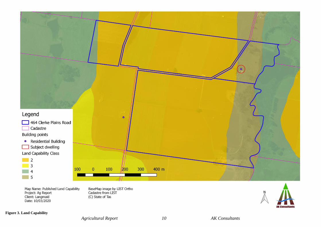
Agricultural Report 10 AK Consultants
Figure 3. Land Capability

Agricultural Report 11 AK Consultants
Figure 4. Setbacks
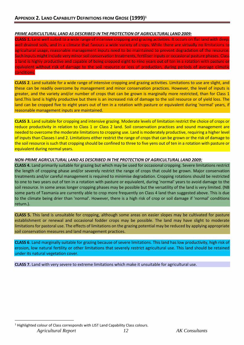
Agricultural Report 12 AK Consultants
APPENDIX 2. LAND CAPABILITY DEFINITIONS FROM GROSE (1999)1
PRIME AGRICULTURAL LAND AS DESCRIBED IN THE PROTECTION OF AGRICULTURAL LAND 2009: CLASS 1. Land well suited to a wide range of intensive cropping and grazing activities. It occurs on flat land with deep, well drained soils, and in a climate that favours a wide variety of crops. While there are virtually no limitations to agricultural usage, reasonable management inputs need to be maintained to prevent degradation of the resource. Such inputs might include very minor soil conservation treatments, fertiliser inputs or occasional pasture phases. Class 1 land is highly productive and capable of being cropped eight to nine years out of ten in a rotation with pasture or equivalent without risk of damage to the soil resource or loss of production, during periods of average climatic conditions.
CLASS 2. Land suitable for a wide range of intensive cropping and grazing activities. Limitations to use are slight, and these can be readily overcome by management and minor conservation practices. However, the level of inputs is greater, and the variety and/or number of crops that can be grown is marginally more restricted, than for Class 1 land.This land is highly productive but there is an increased risk of damage to the soil resource or of yield loss. The land can be cropped five to eight years out of ten in a rotation with pasture or equivalent during 'normal' years, if reasonable management inputs are maintained. CLASS 3. Land suitable for cropping and intensive grazing. Moderate levels of limitation restrict the choice of crops or reduce productivity in relation to Class 1 or Class 2 land. Soil conservation practices and sound management are needed to overcome the moderate limitations to cropping use. Land is moderately productive, requiring a higher level of inputs than Classes I and 2. Limitations either restrict the range of crops that can be grown or the risk of damage to the soil resource is such that cropping should be confined to three to five yens out of ten in a rotation with pasture or equivalent during normal years. NON-PRIME AGRICULTURAL LAND AS DESCRIBED IN THE PROTECTION OF AGRICULTURAL LAND 2009:
CLASS 4. Land primarily suitable for grazing but which may be used for occasional cropping. Severe limitations restrict the length of cropping phase and/or severely restrict the range of crops that could be grown. Major conservation treatments and/or careful management is required to minimise degradation. Cropping rotations should be restricted to one to two years out of ten in a rotation with pasture or equivalent, during 'normal' years to avoid damage to the soil resource. In some areas longer cropping phases may be possible but the versatility of the land is very limited. (NB some parts of Tasmania are currently able to crop more frequently on Class 4 land than suggested above. This is due to the climate being drier than 'normal'. However, there is a high risk of crop or soil damage if 'normal' conditions return.). CLASS 5. This land is unsuitable for cropping, although some areas on easier slopes may be cultivated for pasture establishment or renewal and occasional fodder crops may be possible. The land may have slight to moderate limitations for pastoral use. The effects of limitations on the grazing potential may be reduced by applying appropriate soil conservation measures and land management practices. CLASS 6. Land marginally suitable for grazing because of severe limitations. This land has low productivity, high risk of erosion, low natural fertility or other limitations that severely restrict agricultural use. This land should be retained under its natural vegetation cover. CLASS 7. Land with very severe to extreme limitations which make it unsuitable for agricultural use.
1 Highlighted colour of Class corresponds with LIST Land Capability Class colours.

Agricultural Report 13 AK Consultants
APPENDIX 3. POTENTIAL CONFLICT ISSUES
Tables 1 to 4 describe the frequency and intensity of adjacent activities and the associated issues likely to constrain this use. These are a broad guide only and site specific, cultivar specific and seasonal variations occur. Aside from these specific issues associated with these activities Learmonth et. al. (2007) also provides a comprehensive list of potential land use conflict issues (see Table 5). Tables 1 to 5 provide the rationale behind the recommended minimum buffers contained in Table 6 (Appendix 4).
Table 1. Farming activity - Grazing
Management Activity Issues likely to
constrain the activity Comment
Pasture sowing
Herbicide spraying
Cultivation
Drilling
Spray drift, noise
Noise, dust
Noise, dust
Ground based or aerial – often very early
in the morning
Graze
Noise at certain time eg
weaning calves
Livestock trespass
Tractor
Forage conservation
Mow, Rake, Bale, Cart bales Noise, dust Tractor
Fertiliser spreading Noise Tractor
Insecticide spraying Spray drift
Noise
Ground based or aerial – often very early
in the morning
Table 2. Farming Activity – Poppy crop
Management Activity Issues likely to
constrain the activity Comment
Pre-cultivation spray Spray drift
Noise
Ground based or aerial – often very early
in the morning
Cultivation – several passes (2-4) Noise
Dust
Tractor
Dust is unlikely as soils are likely to be
moist
Lime spreading Noise Tractor
Drilling Noise Tractor
Herbicide sprays (2) Spray drift
Noise
Ground based or aerial often very early in
the morning
Insecticide & fungicide sprays (2-
3)
Spray drift
Noise
Ground based or aerial – likely to be very
early in the morning
Irrigation Spray drift
Noise
Potentially turbid and not potable
Pump
Harvesting Noise Tractor
Potential forage crops after
harvesting, cultivation
Broadcast seed & harrow,
Irrigate
Noise
Noise
Noise, spray drift
Tractor
Tractor
Pump

Agricultural Report 14 AK Consultants
Table 3. Farming Activity - Potato crop
Management Activity Issues likely to
constrain the activity Comment
Pre-cultivation spray Spray drift
Noise
Ground based or aerial – often very early
in the morning
Cultivation – several passes (2-4) Noise
Dust
Tractor
Dust is unlikely as soils are likely to be
moist
Planting Noise
Herbicide spray Spray drift
Noise
Ground based or aerial – often very early
in the morning
Insecticide & fungicide sprays
(5+)
Spray drift
Noise
Ground based or aerial – likely to be very
early in the morning
Fertiliser Spreading Noise
Odour
Tractor
From manure/organic fertilisers
Irrigation Spray drift
Noise
Potentially turbid and not potable
Pump
Harvesting Noise Tractor
Table 4. Farming activity – Strawberries (3 yr rotation)
Management Activity Issues likely to
constrain the activity Comment
Fungicide
Spray drift
Noise
Ground based likely to be very early in
the morning
Herbicide spraying
Spray drift
Noise
Ground based likely to be very early in
the morning
Cultivation Noise
Fertiliser Spray drift
Noise
Ground based likely to be very early in
the morning
Planting By hand
Noise Tractor & traffic
Inter-row maintenance herbicide
and/or mowing
Spray drift
Noise
Ground based likely to be very early in
the morning
Irrigation Spray drift
Noise
Harvesting
Dec -March
By hand
Noise Tractor & traffic

Agricultural Report 15 AK Consultants
Table 5. Typical rural land use conflict issues (Learmonth et al. 2007).
Issue Explanation
Absentee
landholders
Neighbours may be relied upon to manage issues such as bush fires, straying stock, trespassers etc.
while the absentee landholder is at work or away.
Access Traditional or informal ‘agreements’ for access between farms and to parts of farms may break down
with the arrival of new people.
Catchment
management
Design, funding and implementation of land, water and vegetatin management plans are complicated
with larger numbers of rural land-holders with differing perspectives and values.
Clearing Neighbours may object to the clearing of trees, especially when it is done apparently without approvals
or impacts on habitat areas or local amenity.
Cooperation Lack of mutual co-operation through the inability or unwillingness on behalf individuals to contribute
may curtail or limit traditional work sharing practices on-farm or in the rural community.
Dogs Stray domestic dogs and wild dogs attacking livestock and wildlife and causing a nuisance.
Drainage Blocking or changing drainage systems through a lack of maintenance or failure to cooperate and not
respect the rights of others.
Dust Generated by farm and extractive industry operations including cultivating, fallow (bare) ground, farm
vehicles, livestock yards, feed milling, fertiliser spreading etc.
Dwellings Urban or residential dwellings located too close to or affecting an existing rural pursuit or routine land
use practice.
Electric fences Electric shocks to children, horses and dogs. Public safety issues.
Fencing Disagreement about maintenance, replacement, design and cost.
Fire Risk of fire escaping and entering neighbouring property. Lack of knowledge of fire issues and the role
of the Rural Fire Service.
Firearms Disturbance, maiming and killing of livestock and pest animals, illegal use and risk to personal safety.
Flies Spread from animal enclosures or manure and breeding areas.
Heritage
management
Destruction and poor management of indigenous and non indigenous cultural artefacts, structures and
sites.
Lights Bright lights associated with night loading, security etc.
Litter Injury and poisoning of livestock via wind blown and dumped waste. Damage to equipment and
machinery. Amenity impacts.
Noise From farm machinery, scare guns, low flying agricultural aircraft, livestock weaning and feeding, and
irrigation pumps.
Odours Odours arising from piggeries, feedlots, dairies, poultry, sprays, fertiliser, manure spreading, silage,
burning carcases/crop residues.
Pesticides Perceived and real health and environmental concerns over the use, storage and disposal of pesticides
as well as spray drift.
Poisoning Deliberate poisoning and destruction of trees/plants. Spray drift onto non-target plants. Pesticide or
poison uptake by livestock and human health risks.
Pollution Water resources contaminated by effluent, chemicals, pesticides, nutrients and air borne particulates.
Roads Cost and standards of maintenance, slow/wide farm machinery, livestock droving and manure.
Smoke From the burning of crop residues, scrub, pasture and windrows.
Soil erosion Loss of soil and pollution of water ways from unsustainable practices or exposed soils. Lack of
adequate groundcover or soil protection.
Straying livestock Fence damage, spread of disease, damage to crops, gardens and bush/rainforest regeneration.
Theft/vandalism Interference with crops, livestock, fodder, machinery and equipment.
Tree removal Removal of native vegetation without appropriate approvals. Removal of icon trees and vegetation.
Trespass Entering properties unlawfully and without agreement.
Visual/amenity Loss of amenity as a result of reflective structures (igloos, hail netting), windbreaks plantings (loss of
view). Water Competition for limited water supplies, compliance with water regulations, building of dams, changes to
flows. Stock access to waterways. Riparian zone management.
Weeds Lack of weed control particularly noxious weeds, by landholders.
Based on: Smith, RJ (2003) Rural Land Use Conflict: Review of Management Techniques – Final
Report to Lismore Living Centres (PlanningNSW).
Living and Working in Rural Areas. A handbook for managing land use conflict issues on the NSW North
Coast. Learmonth, R., Whitehead, R., Boyd, B., and Fletcher, S. n.d.
Table 1. Typical rural land use conflict issues in the north coast region

Agricultural Report 16 AK Consultants
APPENDIX 4. AGRICULTURAL ENTERPRISES REQUIREMENTS AND POTENTIAL CONSTRAINTS
Table 6 describes the general resource requirements for various agricultural land uses.
Table 6. Resource Requirements for Various Land Uses
Resource Livestock Broad acre crops Vegetables Berries Orchard fruits & vines Nurseries & cut flowers
Forestry plantations Sheep Cattle Dairy Cereals Others Processed Un-processed
Land Capability LC 3-6 LC 3-5/6 LC 3-5 LC 1-4 LC 1-4 LC 1-4 LC 1-4 LC 1-4/5 LC 1-4/5 LC 1-4 or N/A LC 4-6
Minimum paddock sizes
No minimum No minimum To suit grazing 10-15ha min. 5-10ha min. 10ha min. 10ha min. 2-4ha 2-5ha 2-4ha min. 10-20ha min.
Farm size for a "viable" business
5,000-10,000 dse (area depends on rainfall)
5,000-10,000 dse (area depends on rainfall)
Capacity for at least 350 milkers
Broadacre cropping will be a mix of crops in rotation with pasture and livestock. The area required for viability is highly variable.
4-10ha 10-30ha 5-10ha 10-20ha min.
Agricultural Land Mapping Project (3)
333ha 40ha 133ha 25ha 10ha Not defined
Irrigation water Not required Not required Preferable 4-6ML/ha. Not necessary Mostly necessary, 2-3 ML/ha
Necessary, 2-6ML/ha
Necessary, 2-6ML/ha
Necessary, 1-3ML/ha
Necessary, 2-3ML/ha Necessary, small quantity
Not required
Climate specifications
Lower rainfall preferred for wool
No preferences
High rainfall (or irrigation)
Susceptible to spring frosts. Difficult to harvest in humid coastal conditions
Susceptible to spring frosts
Susceptible to spring frosts
Susceptible to spring frosts
High rainfall (or irrigation)
Susceptible to spring frosts for vines. Susceptible to summer rains for cherries. Susceptible to disease in high humidity in March for vines
Preferably low frost risk area
Rainfall above 700-800 mm
Infrastructure Yards & shed Yards, crush, loading ramp
Dairy shed Minimal Irrig facilities Irrig facilities Irrig facilities Irrig facilities Irrig facilities Plastic/glass houses
None
Plant & equipment
Minimal Minimal; hay feeding plant
General purpose tractor, hay/silage feeding
Tractors & implements Tractors & implements
Tractors & implements
Tractors & implements
Tractors & implements
Tractors & implements Small plant None
Market contracts Not required Not required Necessary Not required Generally required Necessary Highly preferred Desired Desired Contracts preferable
Varies
Labour Medium Low High Low Low Low Variable/medium High at times High at times High at times Low
Local services Shearers Vet Vet, dairy shed technician
Agronomist, contractors
Agronomist, contractors
Agronomist, contractors
Agronomist, contractors
Pickers Pickers Pickers Contractors
Regional suitability
Dryer areas good for wool. All areas suitable; larger farm sizes needed for viability.
All areas suitable. Suits small farms.
Economics dictate large area necessary. Needs high rainfall or large water resource for irrigation.
Generally large areas, so need larger paddocks and larger farms.
Generally large areas, so need larger paddocks and larger farms.
Medium sized paddocks & farms; area for crop rotations and irrigation.
Medium sized paddocks & farms; area for crop rotations and irrigation;
Specific site requirements; proximity to markets and transport/carriers.
Specific site requirements; potentially available in most municipalities.
Proximity to markets is important.
Low rainfall areas less preferred.
Recommended min. buffer for individual dwellings (1)
50m to grazing area
50m to grazing area
50m to grazing area, 250m to dairy shed and 300m to effluent storage or continuous application areas (2)
200m to crop 200m to crop 200m to crop 200m to crop 200m to crop 200m to crop 200m to crop 100m from crop for aerial spraying.
Recommended min. buffer for residential areas (1)
50m to grazing area
50m to grazing area
50m to grazing area, 500m to dairy shed
300m to crop 300m to crop 300m to crop 300m to crop 300m to crop 300m to crop 300m to crop Site specific (1)
(1) From (Learmonth, Whitehead, Boyd & Fletcher, 2007). These are industry specific recommended setbacks which do not necessarily align with Planning Scheme Setback requirements. Council should ensure they are aware of attenuation setback requirements for specific activities.
(2) From (State Dairy Effluent Working Group, 1997). (3) The Agricultural Land Mapping Project (Dept of Justice, 2017) defined minimum threshold titles sizes that could potentially sustain a standalone agricultural enterprise.