ceng 491 software design document for …...ceng 491 software design document for the eleron...
TRANSCRIPT
CENG 491
SOFTWARE DESIGN DOCUMENT FOR THE ELERON
RANDOMSOFT
OKAN HARPUT – 1679042 EMRE AKSAN - 1678655 SAMET CAN - 1678812
ÇAĞLAR GÜNDOĞDU - 1679000
17.01.2013
2
Preface
This document contains the software design details for the “The Eleron” software. The document is prepared according to the “IEEE Standard for Information Technology – Systems Design – Software Design Descriptions – IEEE STD 1016 – 1998”. This Software Design Documentation provides a complete description of all the system design and views of the “The Eleron”.

3
Version Date Sections Changed, Added Type of
the Change
Brief Description
1.0 02.12.2012 - A Full Document is Written
2.0
17.01.2013 1.2 2.2.4 3 4 4.1.2 4.1.1.3 Figure 1 Figure 2 Figure 15 Figure 9 Figure 10 Figure 13 Figure 16 Figure 24 Figure 3 Figure 19 All mockups Figure 1 Figure 13 Figure 14 Figure 15 Figure 16 4.1.2
M M M M D D D D D D D D D D M M M A A A A A A
M and D sections are according to v1.0 A sections are according to v2.0
* A: Added, M: Modified, D: Deleted
4
Table of Contents
Preface ................................................................................................................................................. 2
1 Introduction ..................................................................................................................................... 6
1.1 Purpose .................................................................................................................................... 6
1.2 Scope ....................................................................................................................................... 6
1.3 Overview .................................................................................................................................. 6
1.4 Document Conventions ........................................................................................................... 7
2 Design Consideration....................................................................................................................... 8
2.1 Design Objectives .................................................................................................................... 8
2.2 Constraints and Limitations ..................................................................................................... 8
2.2.1 Resource Constraints ....................................................................................................... 8
2.2.2 Time Constraints .............................................................................................................. 8
2.2.3 Integrity Constraints ........................................................................................................ 8
2.2.4 Performance Constraints ................................................................................................. 8
3 Data Design...................................................................................................................................... 9
4 Architectural Design ........................................................................................................................ 9
4.1 Server Architecture ............................................................................................................... 10
4.1.1 Federate and Ambassador Classes ................................................................................ 11
4.1.1.1 Class Diagrams ........................................................................................................... 12
4.1.1.2 Sequential Diagrams .................................................................................................. 15
4.1.2 RTI Interactions Data ..................................................................................................... 15
4.1.3 User Classes ................................................................................................................... 16
4.1.3.1 Class Diagrams ........................................................................................................... 17
4.1.4 Bot Control Classes ........................................................................................................ 18
4.1.4.1 Class Diagrams ........................................................................................................... 19
4.1.4.2 Behavioral Diagram ................................................................................................... 19
4.1.5 Unity-Portico Connection Adapters .............................................................................. 19
4.1.5.1 Class Diagrams ........................................................................................................... 21
4.2 User Client Architecture ........................................................................................................ 23
4.2.1 Class Diagram ................................................................................................................ 23
4.2.2 Sequence Diagram ......................................................................................................... 24
5 Graphical User Interface Design .................................................................................................... 24
5.1 Pre-game Graphical User Interfaces ...................................................................................... 25
5.1.1 Connection Window ...................................................................................................... 25
5
5.1.2 Game Play Settings Window ......................................................................................... 26
5.1.3 Environment Settings .................................................................................................... 27
5.1.4 Controller Configuration Window ................................................................................. 28
5.1.5 Difficulty Settings ........................................................................................................... 29
5.1.6 State Diagram ................................................................................................................ 30
5.1.7 Sequence Diagram ......................................................................................................... 30
5.1.8 Class Diagrams ............................................................................................................... 31
5.2 In-game Graphical User Interface ......................................................................................... 32
5.2.1 Class Diagrams ............................................................................................................... 32
5.2.2 Sequence Diagrams ....................................................................................................... 33
6 Schedule ........................................................................................................................................ 34
7 Traceability Matrix......................................................................................................................... 35

6
1 Introduction
1.1 Purpose This document describes how The Eleron will be structured to satisfy the requirements identified in
the Software Requirements Specification document prepared by RandomSoft Team in their senior
software project. It includes modifications over initial design document.
Requirements Specification document determines software, hardware, functional and nonfunctional
requirements decided to be satisfied and gives a general idea how the system will work. This
document covers the details and different aspects of the project in a comprehensive way and
conceptualizes the overall product that will be formed accurately.
In the design process, it is intended to design an effective and modular product that will satisfy the
needs and constraints of the project. It is also aimed to explain the functional, structural and
behavioral features of the system by using specific types of UML diagrams such as class, sequence,
state diagrams. In order to support these diagrams, graphical user interface prototypes are also
provided in the document.
1.2 Scope The software to be produced is “The Eleron”. In this project it is aimed to connect different
simulation/animation technologies. At the end of the project, a software enabling communication
between HLA compliant simulation and Unity3d game engine will be implemented. To visualize our
work and make the software more attractive, the project is designed on a game which includes
crowd simulation, artificial intelligence and multi-player concept.
Initially, as a show case, the game is planned that two or more players will fight against each other as
two teams and these teams also include AI controlled units. However, after meeting with the
customer, also our supervisor, Umut Durak, it is decided to be a space game.
In this new version, instead of warplanes, space ships will be used and the game will run in a space
environment. Again ai-controlled units will be in game, however, their activities will be limited. Since
we are asked to implement a generic communication layer, it is advised us to spent our resources in
that way by our supervisor. The game will also include 3d models to make it more realistic.
1.3 Overview In this document there are four main chapters describing design details. The second chapter, Design
Considerations, describes the objectives,constraints and limitations of the project. In the third
chapter, Data Design, the data models that will be used in the system are mentioned.
The architecture of the software, main components and interfaces between them and structure of
these components are mentioned in details in chapter four, Architectural Design.
How the graphical user interface will look like and the dynamics behind the interface are explained
in chapter five. Time schedule of the project and the traceability matrix that maps use cases with
design elements can be found in the following sections.

7
1.4 Document Conventions
Term Convention
API Application Programming Interface
HLA High Level Architecture
GUI Graphical User Interface
RTI Run Time Infrastructure
FOM Federation Object Model
AI Artificial Intelligence
SDD Software Design Document
IEEE
Institute of Electrical and Electronics Engineers
AI-Agent Units in the game controlled by AI server
Bot Units in the game controlled by AI server
Federate An HLA compliant simulation entity
Federation Collection of federates connected via the RTI
8
2 Design Consideration
2.1 Design Objectives The application will only run on Windows platforms. Portico is decided to be used as a RTI engine
among other alternatives such as MAK, Certi and etc. Portico is open source RTI software and
supports implementation in Java language. It has also a large community and good documentation.
Portico uses IEEE 1516 interface. In addition, Java is selected as the programming language by
considering below criteria:
It is an object oriented programming language,
There are lots of libraries in Java and it is easy to use,
We are experienced with Java.
As a game engine Unity3D is selected. We are not experienced with game development, so we
choose the game engine by considering which game engine suitable for beginners. Also, it has several
sources of sample codes and tutorials along with large community supports.
2.2 Constraints and Limitations
2.2.1 Resource Constraints
After some research on Run Time Infrastructure (RTI) implementations Portico RTI implementation
was chosen with Java and Eclipse as the development environment. Portico has built-in support for
Local Area Networks; therefore our product will inherit this feature. As a game engine Unity was
chosen.
2.2.2 Time Constraints
Another constraint is time. Since the CEng491 course has schedule which specified before the project
development, time constraints should be met.
2.2.3 Integrity Constraints
Testing has a big role in development process and for a good integrity of modules we will test them
separately by utilizing unit tests. Some modules need completion of other modules so we will focus
on independent modules first. Hierarchically we will continue to develop modules. After we get
modules working correctly, we will start to integrate them to system. We aim not to lose time in this
way.
2.2.4 Performance Constraints
Performance is an important constraint. The Eleron must have a good performance in order to not to
delay the simulation in terms of response time of the system. Also system must be efficient enough
to provide moderate 3D game. The overall performance should not be affected by algorithms used in
the Artificial Intelligence related part that means it should not be slow the application. Since human
players will interact with the game, the game screen must be rendered with speed at least 25 fps.
9
3 Data Design In our system design we do not need to use persistent data which stands for database interactions.
Since the system generally works on instant data such as positions of entities and interactions
between these entities, each entity object is responsible for holding its self-data.
The data exchange between different users and AI units will be provided by Portico RTI
infrastructure. Because of the RTI structure, the data must be sent/received in string format. The
format of these messages is defined in the FOM file. For each message type we are going to use an
Interaction object. Corresponding Interaction objects are mentioned in section 4.1.2. For Interaction
objects to be exchange over the RTI channel they must be serialized into string form and these
strings must be deserialized to corresponding object for use.
Data exchanged between the server and Unity is in type of JSON string. For the entities used in Unity,
related data such as position, interactions and events is serialized to JSON string with specified
format and sent over the network adapter to the server and vice versa. Details are mentioned in
section 4.1.5.
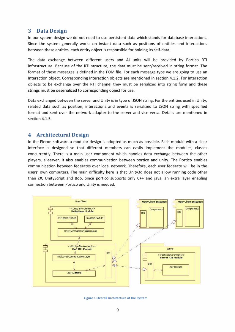
4 Architectural Design In the Eleron software a modular design is adopted as much as possible. Each module with a clear
interface is designed so that different members can easily implement the modules, classes
concurrently. There is a main user component which handles data exchange between the other
players, ai-server. It also enables communication between portico and unity. The Portico enables
communication between federates over local network. Therefore, each user federate will be in the
users’ own computers. The main difficulty here is that Unity3d does not allow running code other
than c#, UnityScript and Boo. Since portico supports only C++ and java, an extra layer enabling
connection between Portico and Unity is needed.
Figure 1 Overall Architecture of the System
10
The connection between Unity and Portico is done via local host connection. There is a layer in Unity
environment which will be implemented in C#. It will read to and listen from a local port. In java side
which is actually Portico environment, there is a java communication layer corresponding to one in
Unity. This will also read to and listen from the same local port that Unity side is using.
The system consists of mainly two phases which are pre-game and in-game phases. In pre-game
phase, a host player, by clicking to “New Game” button, creates a new game with a name by
specifying game options such as environment, craft models, number of ai bots. Later, other users will
be able to join the game over local network either by specifying game name or ip and port number of
the host directly or searching for possible games on the same local area by clicking “Join Game”
button. When the host player creates a game, a federation with specified game name is created on
his computer and at a synchronization point other players are waiting. When a player joins the game,
a federate is created and it is joined to the federation with game name. When all users are ready, for
each connected user and ai-agents a User object is created in Unity side. Each will be visualized with
selected 3d model in pre-game screen. Later, the host player simply clicks the “Start Game” button
and the game starts with initial parameters.
In the game runtime, in-game phase, data of each player is firstly sent to own federate from Unity
game platform. This will be done in every frame update. In federate, this data will be published and
data of other players and ai-agents will be received. This data exchange will be handled over RTI
architecture. When data of others arrives to the federate, it will converted to JSON string and sent to
Unity over Unity-Portico communication layer.
The details of the components are described and illustrated with class and sequence diagrams in the
following sections.
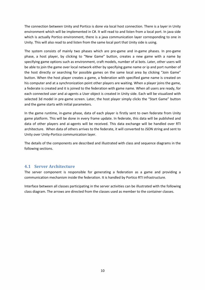
4.1 Server Architecture The server component is responsible for generating a federation as a game and providing a
communication mechanism inside the federation. It is handled by Portico RTI infrastructure.
Interface between all classes participating in the server activities can be illustrated with the following
class diagram. The arrows are directed from the classes used as member to the container classes.
11
Figure 2 Relationship between objects of the server
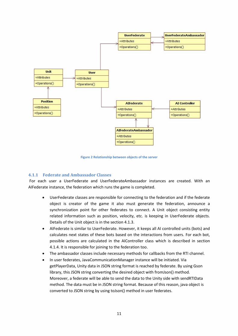
4.1.1 Federate and Ambassador Classes
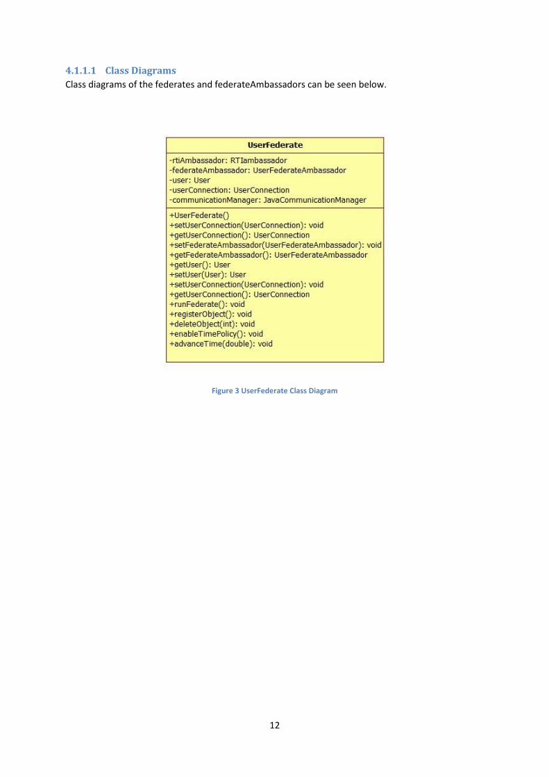
For each user a UserFederate and UserFederateAmbassador instances are created. With an
AIFederate instance, the federation which runs the game is completed.
UserFederate classes are responsible for connecting to the federation and if the federate
object is creator of the game it also must generate the federation, announce a
synchronization point for other federates to connect. A Unit object consisting entity
related information such as position, velocity, etc. is keeping in UserFederate objects.
Details of the Unit object is in the section 4.1.3.
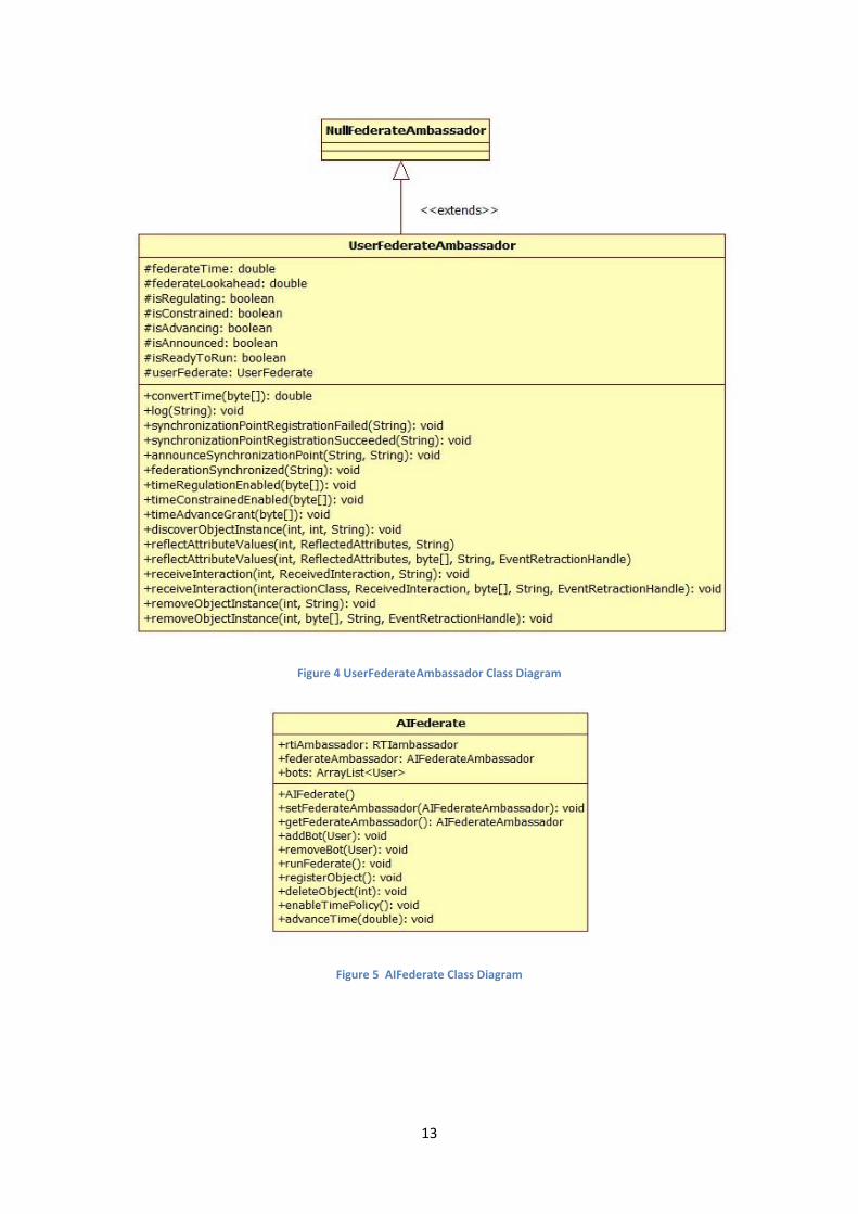
AIFederate is similar to UserFederate. However, it keeps all AI controlled units (bots) and
calculates next states of these bots based on the interactions from users. For each bot,
possible actions are calculated in the AIController class which is described in section
4.1.4. It is responsible for joining to the federation too.
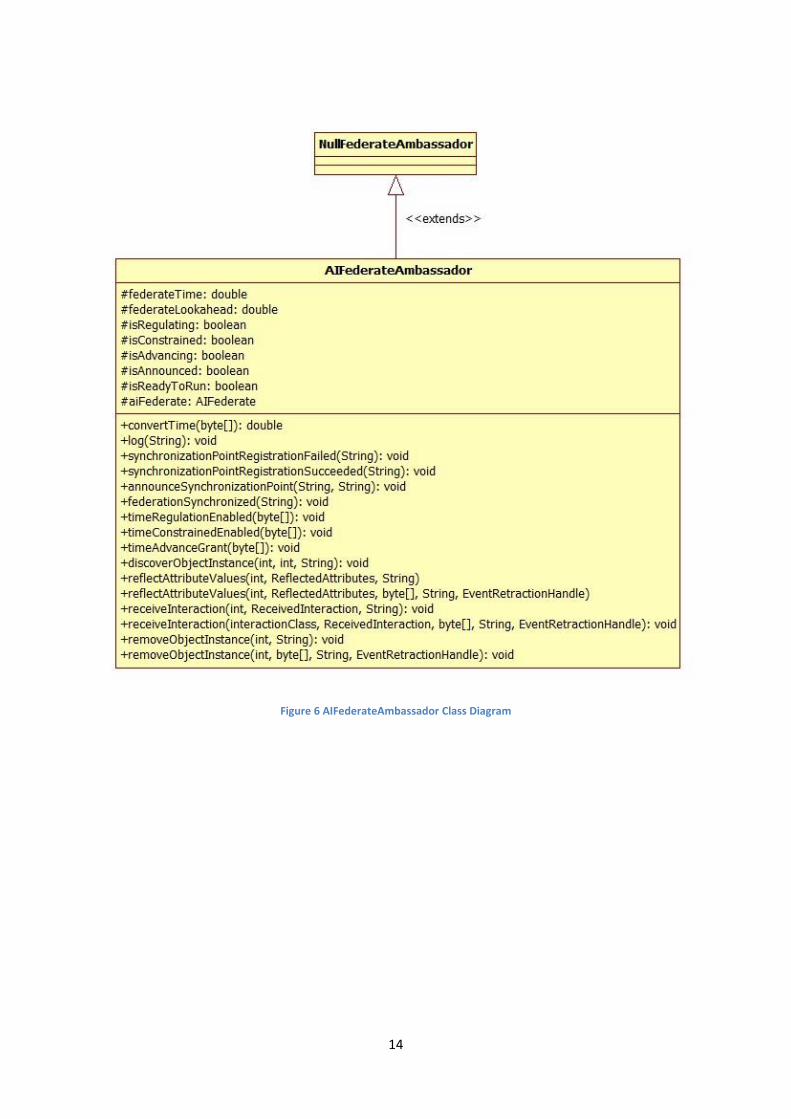
The ambassador classes include necessary methods for callbacks from the RTI channel.
In user federates, JavaCommunicationManager instance will be initiated. Via
getPlayerData, Unity data in JSON string format is reached by federate. By using Gson
library, this JSON string converting the desired object with fromJson() method.
Moreover, a federate will be able to send the data to the Unity side with sendRTIData
method. The data must be in JSON string format. Because of this reason, java object is
converted to JSON string by using toJson() method in user federates.
12
4.1.1.1 Class Diagrams
Class diagrams of the federates and federateAmbassadors can be seen below.
Figure 3 UserFederate Class Diagram
13
Figure 4 UserFederateAmbassador Class Diagram
Figure 5 AIFederate Class Diagram
14
Figure 6 AIFederateAmbassador Class Diagram
15
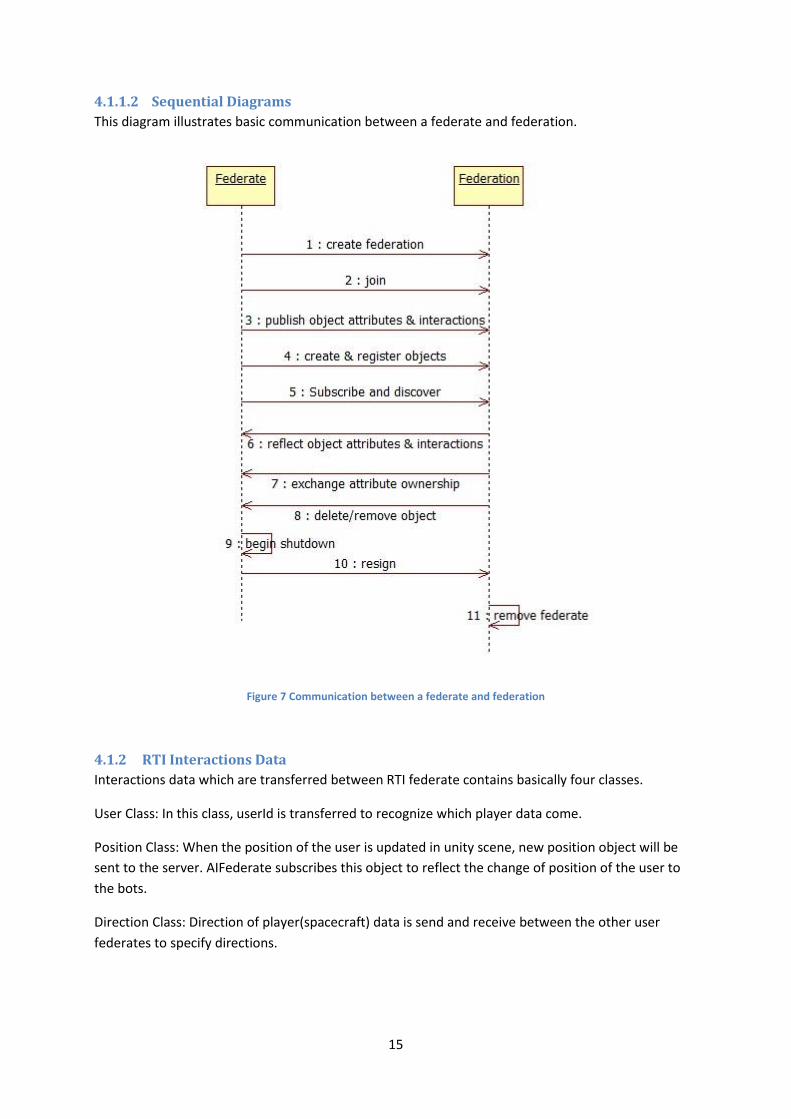
4.1.1.2 Sequential Diagrams
This diagram illustrates basic communication between a federate and federation.
Figure 7 Communication between a federate and federation
4.1.2 RTI Interactions Data
Interactions data which are transferred between RTI federate contains basically four classes.
User Class: In this class, userId is transferred to recognize which player data come.
Position Class: When the position of the user is updated in unity scene, new position object will be
sent to the server. AIFederate subscribes this object to reflect the change of position of the user to
the bots.
Direction Class: Direction of player(spacecraft) data is send and receive between the other user
federates to specify directions.
16
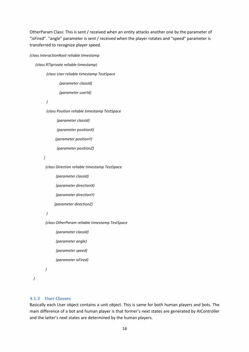
OtherParam Class: This is sent / received when an entity attacks another one by the parameter of
“isFired”. “angle” parameter is sent / received when the player rotates and “speed” parameter is
transferred to recognize player speed.
(class InteractionRoot reliable timestamp
(class RTIprivate reliable timestamp)
(class User reliable timestamp TestSpace
(parameter classId)
(parameter userId)
)
(class Position reliable timestamp TestSpace
(parameter classId)
(parameter positionX)
(parameter positionY)
(parameter positionZ)
)
(class Direction reliable timestamp TestSpace
(parameter classId)
(parameter directionX)
(parameter directionY)
(parameter directionZ)
)
(class OtherParam reliable timestamp TestSpace
(parameter classId)
(parameter angle)
(parameter speed)
(parameter isFired)
)
)
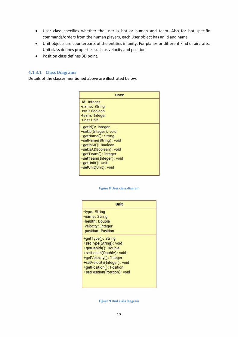
4.1.3 User Classes
Basically each User object contains a unit object. This is same for both human players and bots. The
main difference of a bot and human player is that former’s next states are generated by AIController
and the latter’s next states are determined by the human players.
17
User class specifies whether the user is bot or human and team. Also for bot specific
commands/orders from the human players, each User object has an id and name.
Unit objects are counterparts of the entities in unity. For planes or different kind of aircrafts,
Unit class defines properties such as velocity and position.
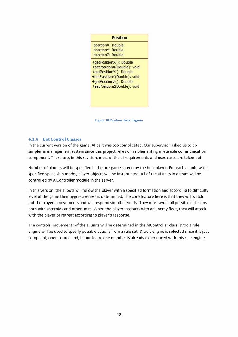
Position class defines 3D point.
4.1.3.1 Class Diagrams
Details of the classes mentioned above are illustrated below:
Figure 8 User class diagram
Figure 9 Unit class diagram
18
Figure 10 Position class diagram
4.1.4 Bot Control Classes
In the current version of the game, AI part was too complicated. Our supervisor asked us to do
simpler ai management system since this project relies on implementing a reusable communication
component. Therefore, in this revision, most of the ai requirements and uses cases are taken out.
Number of ai units will be specified in the pre-game screen by the host player. For each ai unit, with a
specified space ship model, player objects will be instantiated. All of the ai units in a team will be
controlled by AIController module in the server.
In this version, the ai bots will follow the player with a specified formation and according to difficulty
level of the game their aggressiveness is determined. The core feature here is that they will watch
out the player’s movements and will respond simultaneously. They must avoid all possible collisions
both with asteroids and other units. When the player interacts with an enemy fleet, they will attack
with the player or retreat according to player’s response.
The controls, movements of the ai units will be determined in the AIController class. Drools rule
engine will be used to specify possible actions from a rule set. Drools engine is selected since it is java
compliant, open source and, in our team, one member is already experienced with this rule engine.
19
4.1.4.1 Class Diagrams
For the classes mentioned above, detailed information can be illustrated below:
Figure 11 AIController Class Diagram
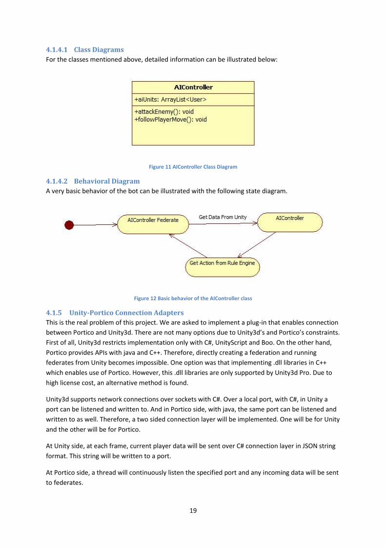
4.1.4.2 Behavioral Diagram
A very basic behavior of the bot can be illustrated with the following state diagram.
Figure 12 Basic behavior of the AIController class
4.1.5 Unity-Portico Connection Adapters
This is the real problem of this project. We are asked to implement a plug-in that enables connection
between Portico and Unity3d. There are not many options due to Unity3d’s and Portico’s constraints.
First of all, Unity3d restricts implementation only with C#, UnityScript and Boo. On the other hand,
Portico provides APIs with java and C++. Therefore, directly creating a federation and running
federates from Unity becomes impossible. One option was that implementing .dll libraries in C++
which enables use of Portico. However, this .dll libraries are only supported by Unity3d Pro. Due to
high license cost, an alternative method is found.
Unity3d supports network connections over sockets with C#. Over a local port, with C#, in Unity a
port can be listened and written to. And in Portico side, with java, the same port can be listened and
written to as well. Therefore, a two sided connection layer will be implemented. One will be for Unity
and the other will be for Portico.
At Unity side, at each frame, current player data will be sent over C# connection layer in JSON string
format. This string will be written to a port.
At Portico side, a thread will continuously listen the specified port and any incoming data will be sent
to federates.
20
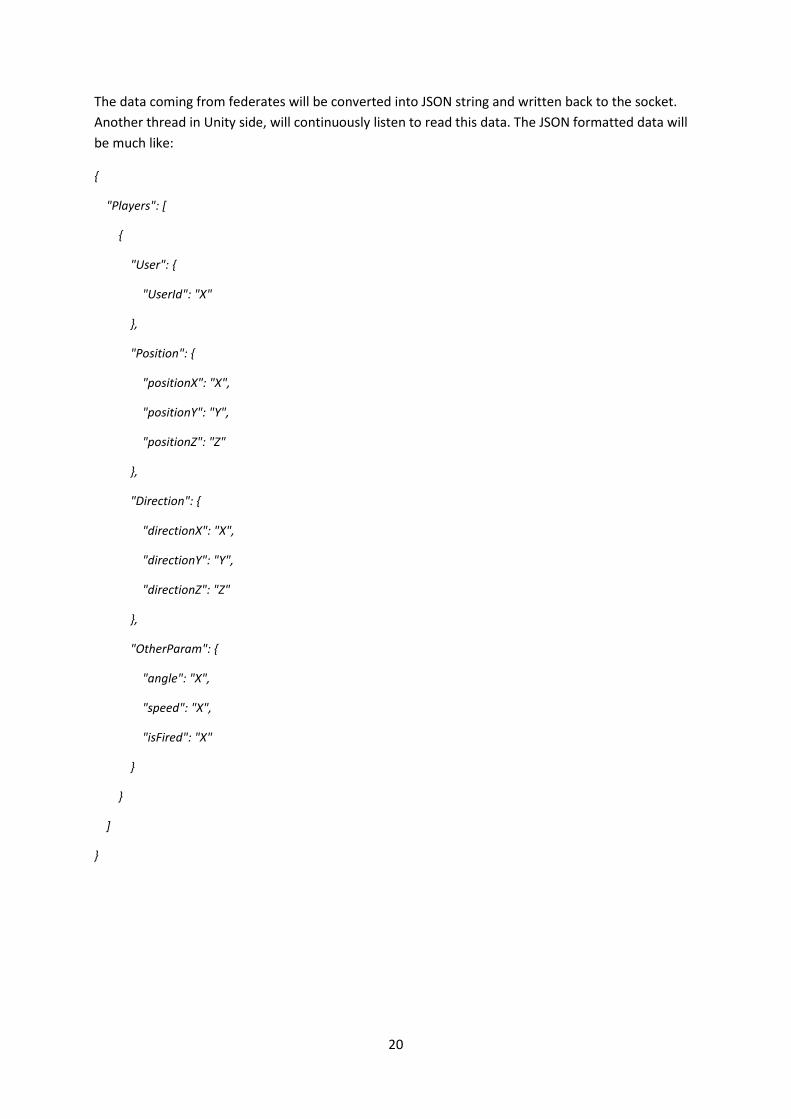
The data coming from federates will be converted into JSON string and written back to the socket.
Another thread in Unity side, will continuously listen to read this data. The JSON formatted data will
be much like:
{
"Players": [
{
"User": {
"UserId": "X"
},
"Position": {
"positionX": "X",
"positionY": "Y",
"positionZ": "Z"
},
"Direction": {
"directionX": "X",
"directionY": "Y",
"directionZ": "Z"
},
"OtherParam": {
"angle": "X",
"speed": "X",
"isFired": "X"
}
}
]
}
21
4.1.5.1 Class Diagrams
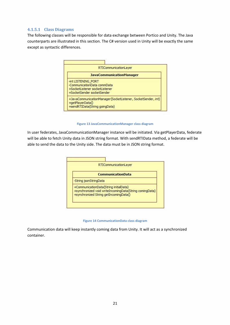
The following classes will be responsible for data exchange between Portico and Unity. The Java
counterparts are illustrated in this section. The C# version used in Unity will be exactly the same
except as syntactic differences.
Figure 13 JavaCommunicationManager class diagram
In user federates, JavaCommunicationManager instance will be initiated. Via getPlayerData, federate
will be able to fetch Unity data in JSON string format. With sendRTIData method, a federate will be
able to send the data to the Unity side. The data must be in JSON string format.
Figure 14 CommunicationData class diagram
Communication data will keep instantly coming data from Unity. It will act as a synchronized
container.
22
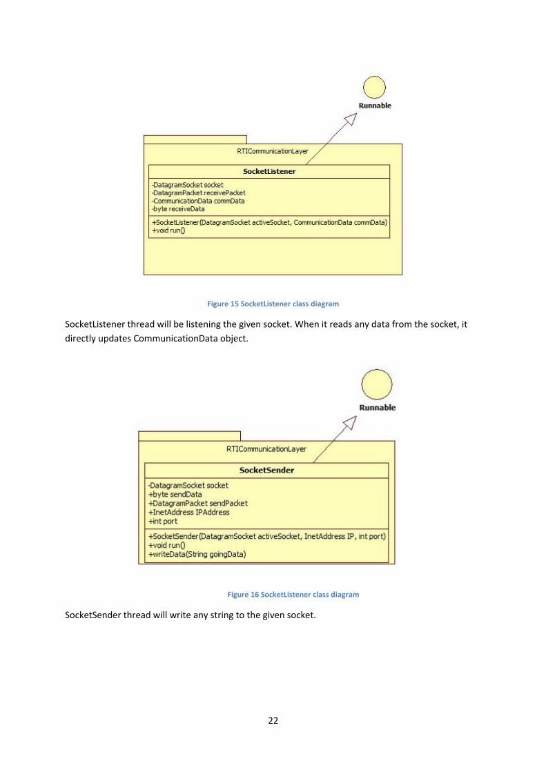
Figure 15 SocketListener class diagram
SocketListener thread will be listening the given socket. When it reads any data from the socket, it
directly updates CommunicationData object.
Figure 16 SocketListener class diagram
SocketSender thread will write any string to the given socket.
23
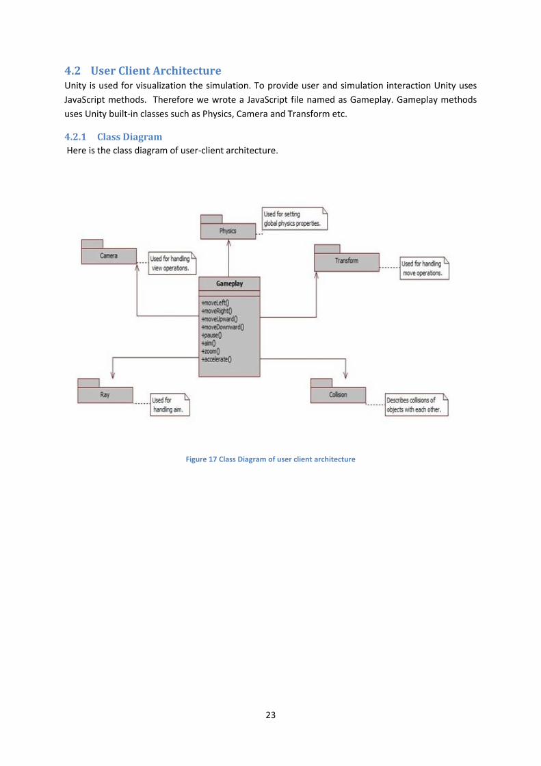
4.2 User Client Architecture Unity is used for visualization the simulation. To provide user and simulation interaction Unity uses
JavaScript methods. Therefore we wrote a JavaScript file named as Gameplay. Gameplay methods
uses Unity built-in classes such as Physics, Camera and Transform etc.
4.2.1 Class Diagram
Here is the class diagram of user-client architecture.
Figure 17 Class Diagram of user client architecture
24
4.2.2 Sequence Diagram
Here is the sequence diagram of user-client architecture.
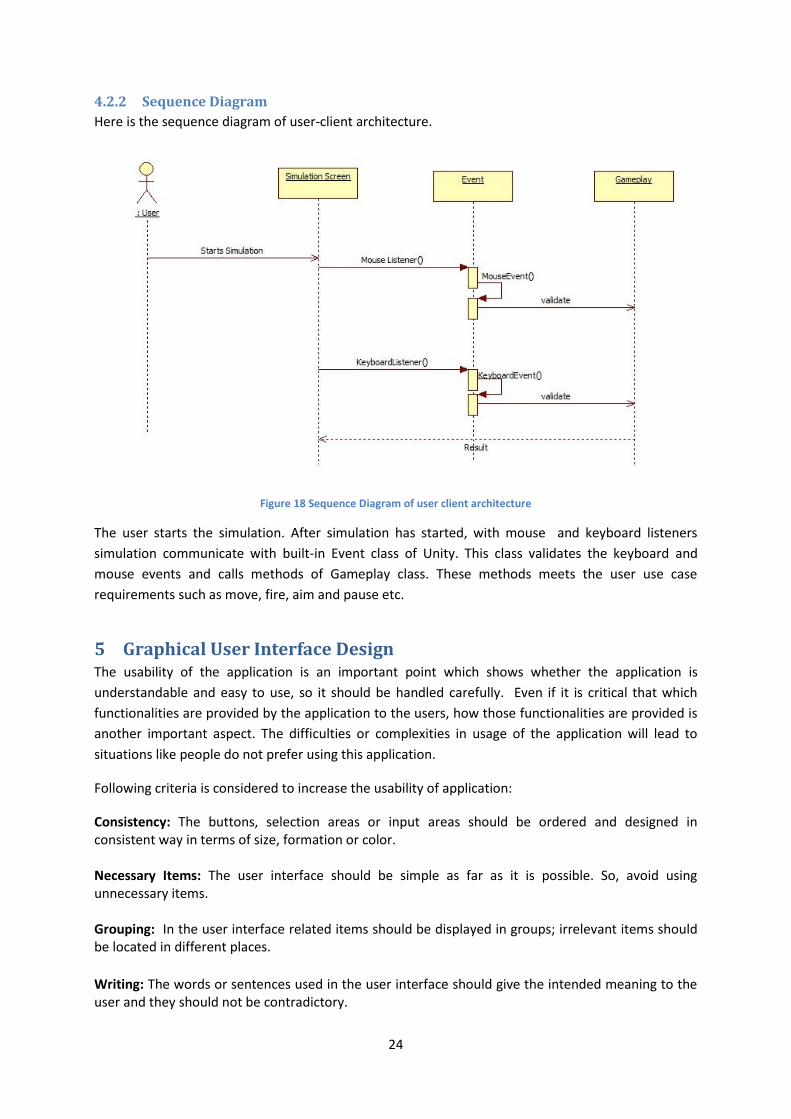
Figure 18 Sequence Diagram of user client architecture
The user starts the simulation. After simulation has started, with mouse and keyboard listeners
simulation communicate with built-in Event class of Unity. This class validates the keyboard and
mouse events and calls methods of Gameplay class. These methods meets the user use case
requirements such as move, fire, aim and pause etc.
5 Graphical User Interface Design The usability of the application is an important point which shows whether the application is
understandable and easy to use, so it should be handled carefully. Even if it is critical that which
functionalities are provided by the application to the users, how those functionalities are provided is
another important aspect. The difficulties or complexities in usage of the application will lead to
situations like people do not prefer using this application.
Following criteria is considered to increase the usability of application:
Consistency: The buttons, selection areas or input areas should be ordered and designed in consistent way in terms of size, formation or color. Necessary Items: The user interface should be simple as far as it is possible. So, avoid using unnecessary items. Grouping: In the user interface related items should be displayed in groups; irrelevant items should be located in different places.
Writing: The words or sentences used in the user interface should give the intended meaning to the user and they should not be contradictory.
25
Mistakes: The user should be able to recover the mistakes which he/she created in the graphical user interface.
When creating the user interface, above criteria is taken into consideration. The following interfaces are written to show our general idea about how user interface will be. The exact interfaces will be different in the design of the project.
5.1 Pre-game Graphical User Interfaces
5.1.1 Connection Window
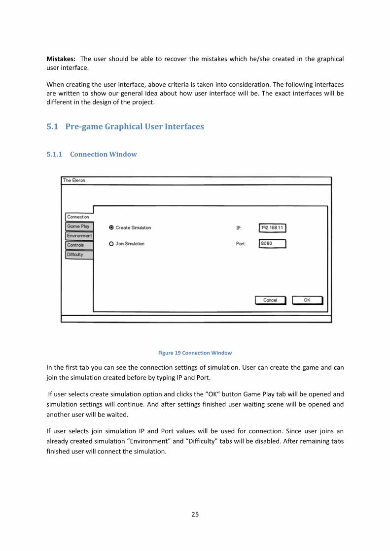
Figure 19 Connection Window
In the first tab you can see the connection settings of simulation. User can create the game and can
join the simulation created before by typing IP and Port.
If user selects create simulation option and clicks the “OK“ button Game Play tab will be opened and
simulation settings will continue. And after settings finished user waiting scene will be opened and
another user will be waited.
If user selects join simulation IP and Port values will be used for connection. Since user joins an
already created simulation “Environment” and “Difficulty” tabs will be disabled. After remaining tabs
finished user will connect the simulation.

26
5.1.2 Game Play Settings Window
Figure 20 Game Play window
User can select his/her own plane form this menu. To select a plane user should slide images and find
the plane he/she wanted to select. After finding plane model user should click to “Select” button to
choose.
Number of agents can be set from the spin box. This will set the number of AI agents in one team.
Clicking “OK” button will lead the next step which is “Strategy” settings.

27
5.1.3 Environment Settings
Figure 21 Environment Window
Environment settings will be set from this window. There are one select box in this tab. And it is used
for selecting simulation map.

28
5.1.4 Controller Configuration Window
Figure 22 Controls Window
User can configure the buttons to use the functionalities of the game according to his/her desires. All
functionalities of the game are shown on the controls panel. System enables configuration after user
clicked the functionality, any keyboard button or mouse can be assigned to the clicked functionality.
The default button changes configurations as in factory default settings.
29
5.1.5 Difficulty Settings
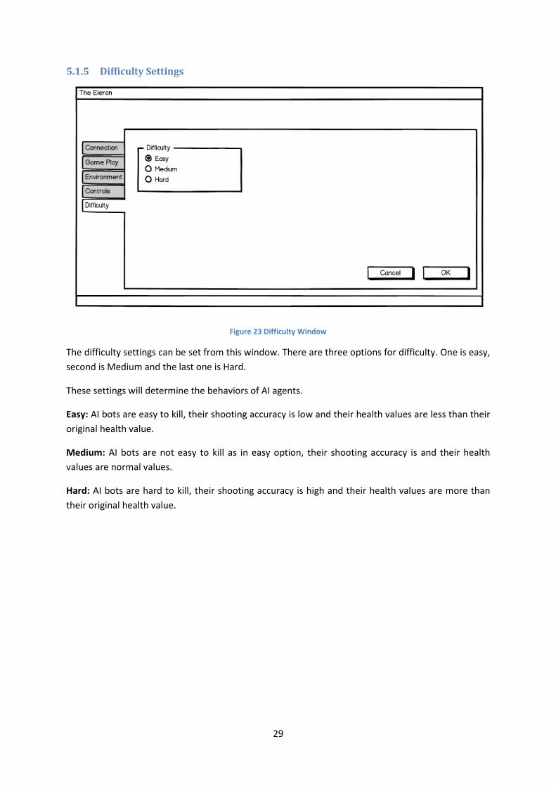
Figure 23 Difficulty Window
The difficulty settings can be set from this window. There are three options for difficulty. One is easy,
second is Medium and the last one is Hard.
These settings will determine the behaviors of AI agents.
Easy: AI bots are easy to kill, their shooting accuracy is low and their health values are less than their
original health value.
Medium: AI bots are not easy to kill as in easy option, their shooting accuracy is and their health
values are normal values.
Hard: AI bots are hard to kill, their shooting accuracy is high and their health values are more than
their original health value.
30
5.1.6 State Diagram
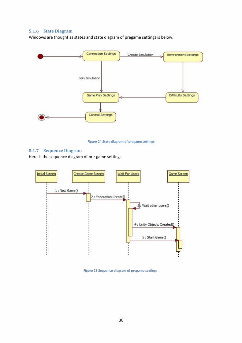
Windows are thought as states and state diagram of pregame settings is below.
Figure 24 State diagram of pregame settings
5.1.7 Sequence Diagram
Here is the sequence diagram of pre-game settings.
Figure 25 Sequence diagram of pregame settings

31
5.1.8 Class Diagrams
We used JavaScript in Unity side of the project; JavaScript uses prototype-based inheritance. This
means there is no distinction between classes and instances as in other OO languages (like Java).
There are just objects. Therefore we consider each JavaScript file as classes. The methods and
variables in each JavaScript files showed as class methods and class variables. Below is the class
diagram of pregame settings.
Figure 26 Class diagram of pregame settings
32
5.2 In-game Graphical User Interface
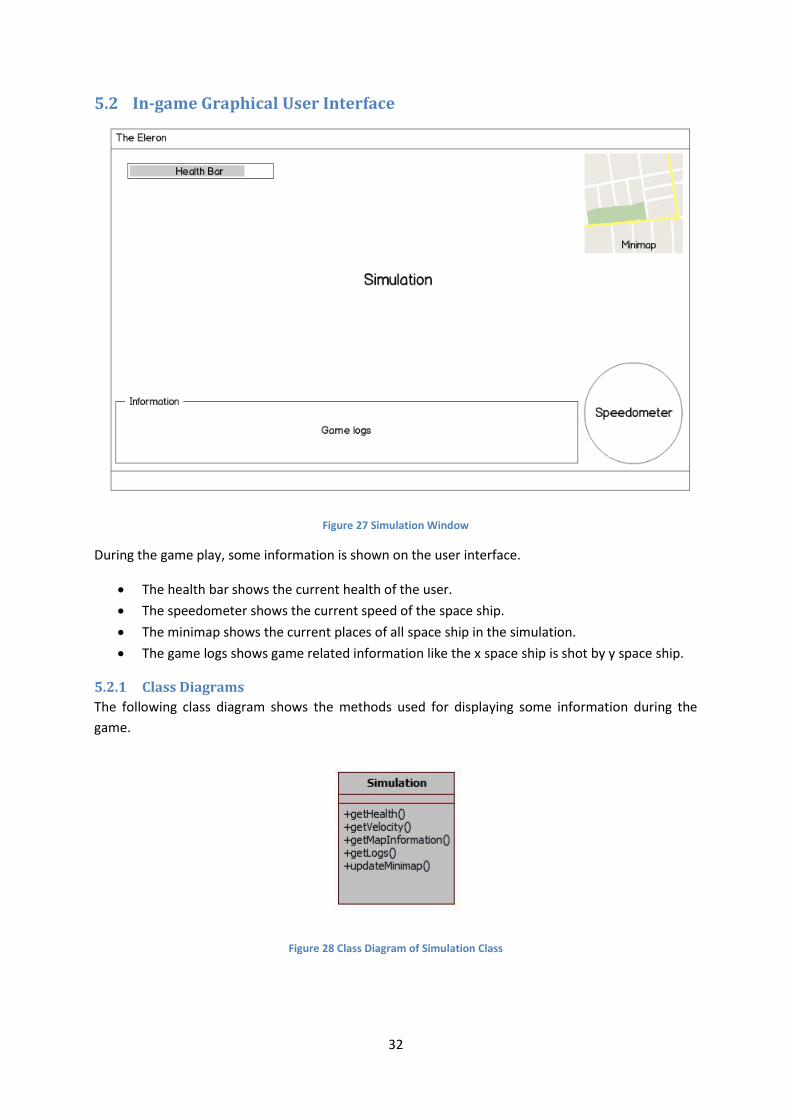
Figure 27 Simulation Window
During the game play, some information is shown on the user interface.
The health bar shows the current health of the user.
The speedometer shows the current speed of the space ship.
The minimap shows the current places of all space ship in the simulation.
The game logs shows game related information like the x space ship is shot by y space ship.
5.2.1 Class Diagrams
The following class diagram shows the methods used for displaying some information during the
game.
Figure 28 Class Diagram of Simulation Class
33
5.2.2 Sequence Diagrams
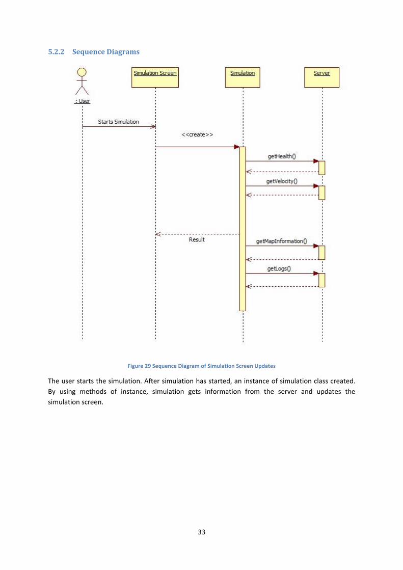
Figure 29 Sequence Diagram of Simulation Screen Updates
The user starts the simulation. After simulation has started, an instance of simulation class created.
By using methods of instance, simulation gets information from the server and updates the
simulation screen.
34
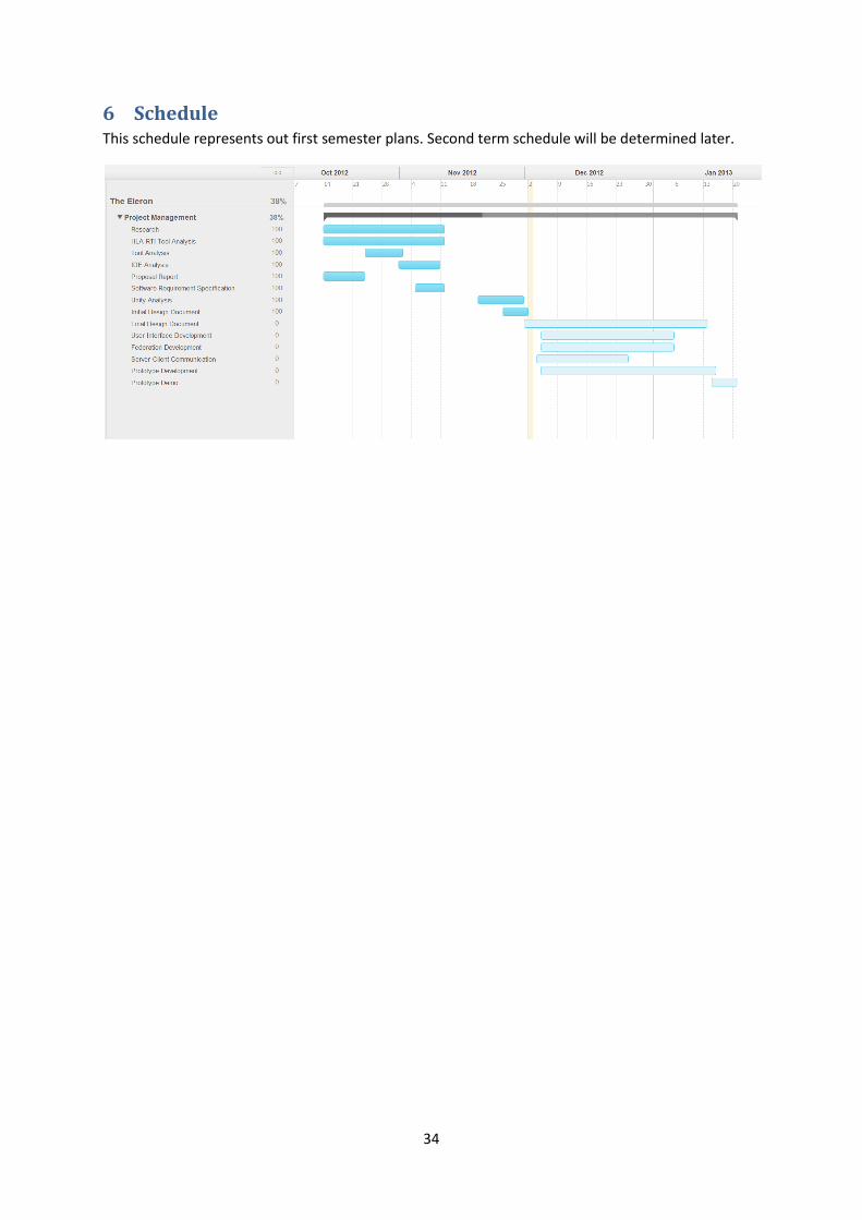
6 Schedule This schedule represents out first semester plans. Second term schedule will be determined later.
35
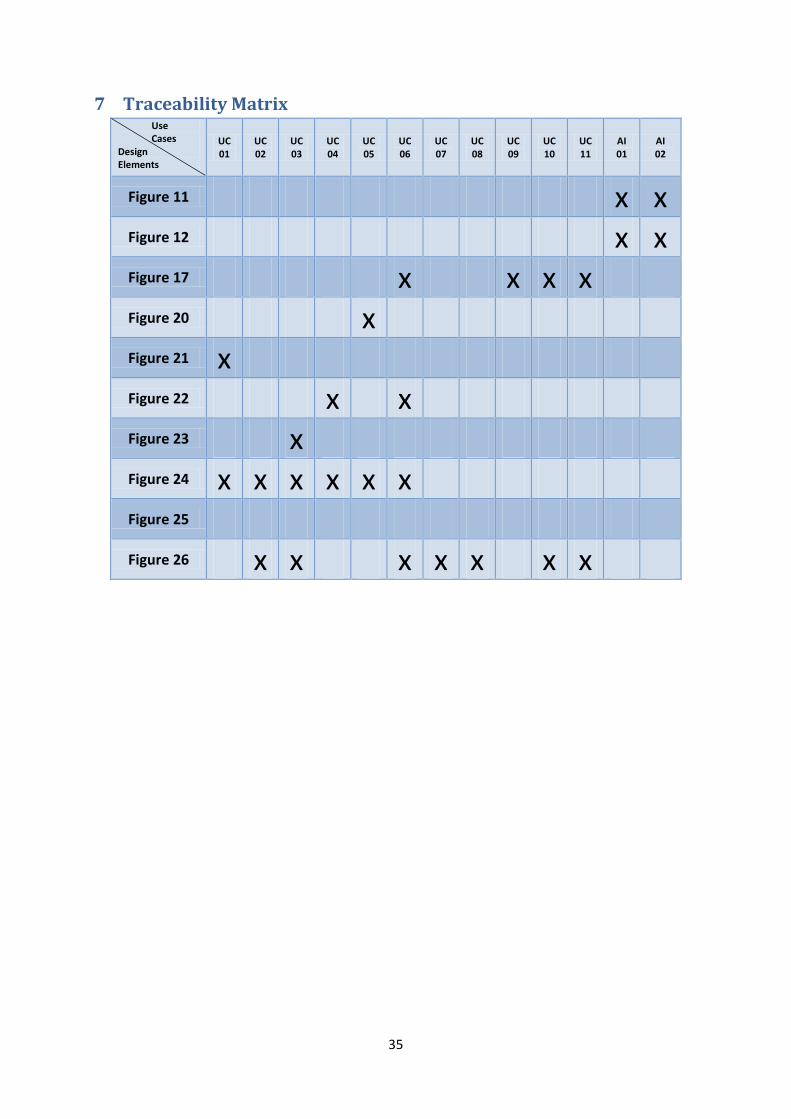
7 Traceability Matrix Use Cases Design Elements
UC 01
UC 02
UC 03
UC 04
UC 05
UC 06
UC 07
UC 08
UC 09
UC 10
UC 11
AI 01
AI 02
Figure 11 x x Figure 12 x x Figure 17 x x x x Figure 20 x Figure 21 x Figure 22 x x Figure 23 x Figure 24 x x x x x x Figure 25 Figure 26 x x x x x x x