cement stabilized soil as a road base material for use in
TRANSCRIPT

ENGINEER21
ENGINEER - Vol. L, No. 01, pp. [page range], 2017 © The Institution of Engineers, Sri Lanka
1 ENGINEER
Cement Stabilized Soil as a Road Base Material for use in Sri Lankan Roads
W.W. Bandara, W.K. Mampearachchi and K.H.S.M. Sampath
Abstract: The elastic modulus of the lower quality coarse–grained sandy materials available in Sri Lanka is higher than the elastic modulus of fine–grained silty and clayed materials. Although these locally available soils can be stabilized using cement, due to the non-availability of appropriate guidelines, several issues can arise when they are stabilized. The strength of the materials can be measured using the California Bearing Ratio (CBR). However in certain specifications, it is the Unconfined Compressive Strength (UCS)that is specified for stabilized material. Therefore, the first phase of this study was focused on identifying the correct way to measure the strength of stabilized materials. The study confirmed that the strength of a Cement Stabilized Soil Base (CSB) should be measured using the UCS. Furthermore, in road pavements with a stabilized base, the most critical tensile stress and strain occur at the bottom of the stabilized layer. To minimize fatigue cracking, this tensile stress at the bottom of the stabilized layer has to be controlled. However, empirical design guidelines used in pavement designs cannot be used to analyse the mechanistic behaviour of pavement layers. Hence, during the second phase of this study, cement stabilized pavements were analysed using a Mechanistic-Empirical Method (MEM). A pavement design chart for pavements with a CSB layer was developed for various subgrade and traffic classes using the MEM software KENLAYER. Keywords: Cement Stabilized Soil Base (CSB), Unconfined Compressive Strength (UCS), California Bearing Ratio (CBR), Mechanistic-Empirical Method 1. Background For many years in Sri Lanka, aggregate bases have been used in road construction work. However, quarries that produce aggregates are not commonly available in the country. As an example, for road construction in the northern part of Sri Lanka, aggregates have to be transported from the north central province. Furthermore, the number of available rocks is also gradually decreasing due to various factors related to their usage and ownership and also due to ecological reasons. As a result, cement stabilized soil is now being introduced as an economically viable alternative material for use in road bases. Soil stabilization is the alteration of the properties of soil to improve its engineering performance through its strength, stiffness, compressibility, permeability and workability. In the last few decades, soil – cement stabilization has been more widely used in pavement construction compared to other methods, because of the significant improvements it can make to soil properties. It is found that the engineering behaviour of a cement stabilized base and that of a granular
base when under traffic loading are not similar. Therefore, it has become necessary to study how the engineering properties of a cement stabilized base conforming to the required specifications can be achieved. The main reason for this study was the failures that occurred in several road rehabilitation projects in the northern part of the country which had used cement stabilized sub-bases for the construction of the roads concerned. These failures which occurred during the early stages of operation (during the contractor’s liability period) of the roads made the roads unsatisfactorily. According to the Consultant’s Engineer, the main reasons for those failures
Eng. W.W. Bandara, AMIE(Sri Lanka), B.Sc.(Hons) (Peradeniya), M.Sc (Moratuwa), Department of Civil Engineering, University of Moratuwa. Email:[email protected]
Eng. (Prof.) W. K. Mampearachchi, C.Eng., MIE(Sri Lanka), B.Sc. Eng (Moratuwa), MSCE (South Florida), Ph.D.(Florida), Professor of Civil Engineering, Department of Civil Engineering, University of Moratuwa. Email:[email protected]
Mr.K.H.S.M. Sampath, Student Member of IESL, B.Sc. (Hons) (Moratuwa), M.Sc. Candidate, Department of Civil Engineering, University of Moratuwa. Email: [email protected]
ENGINEER - Vol. L, No. 01, pp. [21 - 29], 2017© The Institution of Engineers, Sri Lanka

ENGINEER 22ENGINEER 2
were the use of improper cement-soil proportions, unsuitability of the soil used for the stabilization, use of improper mixing methods and the lack of technical guidance. Thus, there was a need for a study to identify methods and specifications that are appropriate to stabilizing the locally available soils. Through a literature survey, it was identified that cement could be used to stabilize almost all types of soils [1]. Organic soils, highly plastic clays, and at times poorly reacting sandy soils are however exceptions. Typically, the most economically stabilized soil can be produced by using soil which contains 5% - 35% of particles lower than 0.075 mm in size. For the cement treatment, it is usually unacceptable to use soils containing more than 2%of organic material [1]. In most applications, Type I or Type II Portland cement is normally used and the cement content can vary from 4% to 16% of the dry weight of soil. Generally, as the clay portion of the soil increases, the quantity of cement required also increases. The particle size distribution of ordinary Portland cement is quite well defined falling within a range of 0.5-100 microns with a mean of 20 microns [2]. The larger particles of cement never hydrate completely, and it has been found that finely ground cement will produce higher strengths than the same amount of cement containing larger particles. Since finely ground cement is expensive to produce, it is recommended to replace the larger particles of cement with smaller particles of inert filler[2]. The elastic modulus of granular material and subgrade soil are nonlinear as it varies with the level of stresses [3]. The elastic modulus to be used with layered systems is the resilient modulus obtained from repeated unconfined or triaxial tests. The resilient modulus of granular materials increases as the stress intensity increases while that of fine grained soil decreases with the increase of the stress intensity. Most granular materials cannot take any tension. Unfortunately, when they are used as a base or as a sub base on a weaker subgrade, the horizontal stresses caused by applied loads will most likely to be in tension. However, these materials can still take tensile force if the tension is smaller than the pre-compression caused by geostatic or other in situ stresses. The combined stress (including insitu stresses)
cannot become negative since when it is reduced to zero, the particles will separate out resulting in no stress. The strength of road subgrades, soil bases and subbases are commonly assessed in terms of the California Bearing Ratio (CBR) which is dependent on the type of soil used and its density and moisture content. Thus, it is important to use correct test procedures to assess the properties of a cement stabilized road base [4]. After it is stabilized, a soil layer will act as a soft and low strength concrete with linear elastic properties. Therefore, the behaviour of a stabilized soil layer is different from that of an un-stabilized soil layer. Croney [5] has found that the strength of a stabilized material will often continue to increase for a period of several years from the time of its construction. In a road structure with either a stabilized base or a subbase, the most critical tensile stress or strain will be located at the bottom of the stabilized layer [6]. Therefore, the tensile stress at the bottom of cement treated layers can cause fatigue cracking. The elastic modulus and the tensile strain at the bottom of cement treated layers are considered for the detailed analysis of a stabilized layer. The strength of the stabilized base and the subbase are commonly assessed using the Unconfined Compressive Strength (UCS)[7]. As revealed by Lilley [8] and as shown below, the elastic modulus and the compressive strength will vary with the type of material to be stabilized. These relationships can be used to analyze a pavement.
For lean concrete and high quality coarse-
grained material, E = 57,500 (CS)1/2 …(1)
For lower quality coarse-grained and sandy material,
E = 1200. CS … (2) For silty and clayey fine-grained material,
E = 440. CS + 0.28 (CS)2 …(3) Where E – Modulus of elasticity in psi CS – Compressive Strength in psi
A damage analysis has been performed for both fatigue cracking and permanent deformation (rutting). Fatigue analysis is based on the horizontal tensile strain at the bottom of the specified layers, usually the Hot-Mix Asphalt
3 ENGINEER
(HMA) or cemented layers. Rutting analysis is based on the vertical tensile strain at the top of the specified layers, usually the subgrade or the lowest layer. The failure criterion for fatigue cracking is expressed as the allowable number of load repetitions (N) that will prevent fatigue cracking. The allowable number of load repetitions (N) for a cemented material layer is given by the revision to the guide issued by Austroads in November 1997 as indicated below (Equation 4):
N = (k/µԐ )12 …(4) Where µԐ - Tensile strain of the bottom of the Cement Stabilized Base (micro strain) The numerator k depends on the stiffness of the material as indicated in Table 1;
Table 1 – Value of k
Modulus of Cemented Material (MPa) Value of k
2000 440 3500 350 5000 310 10000 260 15000 240
The failure criterion for permanent deformation (rutting) is as expressed in Equation 5 given below:
Nd = f4 (Ԑ c)-f5 ... (5)
Where Nd-Allowable number of load repetitions to limit permanent deformation Ԑ c- Compressive strain on the top of the subgrade f4 and f5 – Constants determined from road tests or field performance. The values suggested for f4 and f5 by the Asphalt Institute in 1982 are 1.365 x 10⁻⁹and 4.477. [9] The ‘Standard Specifications for Construction and Maintenance of Roads and Bridges’ published by the Institute for Construction Training and Development (ICTAD) in 2009 (i.e., SSCM-2009) gives several specifications that need to be followed during a construction process [10]. These construction requirements are based on Overseas Road Note 31 (1993).
2. Problem Statement The Road Development Authority (RDA) has proposed to rehabilitate several gravel roads with CSBs. The B60 and B424 roads have been constructed based on the available guidelines. However, the performance of these two roads have been unsatisfactory (see Figure 1) due to several failures that occurred during their construction and operation periods (To maintain the two roads at an acceptable level a heavy cost has to be incurred on road maintenance). The contractor too had encountered technical problems during their construction.
Figure 1 - Distresses observed on the B424 Road From the comments made by the engineers on the observed distresses, the following can be identified as the main causes for the failures: Use of a lower cement content (1%) which
satisfies the CBR specifications for cement stabilised soil base only in certain sections
Improper mixing of cement at the site Difficulty in achieving the required
compaction (98%) with respect to modified proctor density
Use of higher cement content in certain sections than what is specified
Use of poor graded soil and not using curing after construction
Thus, a research on the stabilization of locally available soils using cement and the elimination of improper practices to prevent premature distresses becomes essential. 3. Objectives Based on the above mentioned factors, the study was conducted with the following objectives:

ENGINEER23ENGINEER 2
were the use of improper cement-soil proportions, unsuitability of the soil used for the stabilization, use of improper mixing methods and the lack of technical guidance. Thus, there was a need for a study to identify methods and specifications that are appropriate to stabilizing the locally available soils. Through a literature survey, it was identified that cement could be used to stabilize almost all types of soils [1]. Organic soils, highly plastic clays, and at times poorly reacting sandy soils are however exceptions. Typically, the most economically stabilized soil can be produced by using soil which contains 5% - 35% of particles lower than 0.075 mm in size. For the cement treatment, it is usually unacceptable to use soils containing more than 2%of organic material [1]. In most applications, Type I or Type II Portland cement is normally used and the cement content can vary from 4% to 16% of the dry weight of soil. Generally, as the clay portion of the soil increases, the quantity of cement required also increases. The particle size distribution of ordinary Portland cement is quite well defined falling within a range of 0.5-100 microns with a mean of 20 microns [2]. The larger particles of cement never hydrate completely, and it has been found that finely ground cement will produce higher strengths than the same amount of cement containing larger particles. Since finely ground cement is expensive to produce, it is recommended to replace the larger particles of cement with smaller particles of inert filler[2]. The elastic modulus of granular material and subgrade soil are nonlinear as it varies with the level of stresses [3]. The elastic modulus to be used with layered systems is the resilient modulus obtained from repeated unconfined or triaxial tests. The resilient modulus of granular materials increases as the stress intensity increases while that of fine grained soil decreases with the increase of the stress intensity. Most granular materials cannot take any tension. Unfortunately, when they are used as a base or as a sub base on a weaker subgrade, the horizontal stresses caused by applied loads will most likely to be in tension. However, these materials can still take tensile force if the tension is smaller than the pre-compression caused by geostatic or other in situ stresses. The combined stress (including insitu stresses)
cannot become negative since when it is reduced to zero, the particles will separate out resulting in no stress. The strength of road subgrades, soil bases and subbases are commonly assessed in terms of the California Bearing Ratio (CBR) which is dependent on the type of soil used and its density and moisture content. Thus, it is important to use correct test procedures to assess the properties of a cement stabilized road base [4]. After it is stabilized, a soil layer will act as a soft and low strength concrete with linear elastic properties. Therefore, the behaviour of a stabilized soil layer is different from that of an un-stabilized soil layer. Croney [5] has found that the strength of a stabilized material will often continue to increase for a period of several years from the time of its construction. In a road structure with either a stabilized base or a subbase, the most critical tensile stress or strain will be located at the bottom of the stabilized layer [6]. Therefore, the tensile stress at the bottom of cement treated layers can cause fatigue cracking. The elastic modulus and the tensile strain at the bottom of cement treated layers are considered for the detailed analysis of a stabilized layer. The strength of the stabilized base and the subbase are commonly assessed using the Unconfined Compressive Strength (UCS)[7]. As revealed by Lilley [8] and as shown below, the elastic modulus and the compressive strength will vary with the type of material to be stabilized. These relationships can be used to analyze a pavement.
For lean concrete and high quality coarse-
grained material, E = 57,500 (CS)1/2 …(1)
For lower quality coarse-grained and sandy material,
E = 1200. CS … (2) For silty and clayey fine-grained material,
E = 440. CS + 0.28 (CS)2 …(3) Where E – Modulus of elasticity in psi CS – Compressive Strength in psi
A damage analysis has been performed for both fatigue cracking and permanent deformation (rutting). Fatigue analysis is based on the horizontal tensile strain at the bottom of the specified layers, usually the Hot-Mix Asphalt
3 ENGINEER
(HMA) or cemented layers. Rutting analysis is based on the vertical tensile strain at the top of the specified layers, usually the subgrade or the lowest layer. The failure criterion for fatigue cracking is expressed as the allowable number of load repetitions (N) that will prevent fatigue cracking. The allowable number of load repetitions (N) for a cemented material layer is given by the revision to the guide issued by Austroads in November 1997 as indicated below (Equation 4):
N = (k/µԐ )12 …(4) Where µԐ - Tensile strain of the bottom of the Cement Stabilized Base (micro strain) The numerator k depends on the stiffness of the material as indicated in Table 1;
Table 1 – Value of k
Modulus of Cemented Material (MPa) Value of k
2000 440 3500 350 5000 310 10000 260 15000 240
The failure criterion for permanent deformation (rutting) is as expressed in Equation 5 given below:
Nd = f4 (Ԑ c)-f5 ... (5)
Where Nd-Allowable number of load repetitions to limit permanent deformation Ԑ c- Compressive strain on the top of the subgrade f4 and f5 – Constants determined from road tests or field performance. The values suggested for f4 and f5 by the Asphalt Institute in 1982 are 1.365 x 10⁻⁹and 4.477. [9] The ‘Standard Specifications for Construction and Maintenance of Roads and Bridges’ published by the Institute for Construction Training and Development (ICTAD) in 2009 (i.e., SSCM-2009) gives several specifications that need to be followed during a construction process [10]. These construction requirements are based on Overseas Road Note 31 (1993).
2. Problem Statement The Road Development Authority (RDA) has proposed to rehabilitate several gravel roads with CSBs. The B60 and B424 roads have been constructed based on the available guidelines. However, the performance of these two roads have been unsatisfactory (see Figure 1) due to several failures that occurred during their construction and operation periods (To maintain the two roads at an acceptable level a heavy cost has to be incurred on road maintenance). The contractor too had encountered technical problems during their construction.
Figure 1 - Distresses observed on the B424 Road From the comments made by the engineers on the observed distresses, the following can be identified as the main causes for the failures: Use of a lower cement content (1%) which
satisfies the CBR specifications for cement stabilised soil base only in certain sections
Improper mixing of cement at the site Difficulty in achieving the required
compaction (98%) with respect to modified proctor density
Use of higher cement content in certain sections than what is specified
Use of poor graded soil and not using curing after construction
Thus, a research on the stabilization of locally available soils using cement and the elimination of improper practices to prevent premature distresses becomes essential. 3. Objectives Based on the above mentioned factors, the study was conducted with the following objectives:

ENGINEER 24ENGINEER 4
To identify and develop a relationship between the cement content, CBR and UCS of a CSB
To identify a suitable method for measuring the strength of a CSB, i.e., CBR or UCS
To develop a pavement design chart for CSB pavements for various traffic and subgrade classes
4. Methodology 4.1 Determination of the Properties of
Available Soils used for CSBs The test reports pertaining to borrow pit samples of natural soils that were selected for the CSBs of the proposed rehabilitation road projects were collected and the properties of the soils were determined through standard laboratory tests. Thereafter, a soil classification was done as per the Unified Soil Classification System. [11]
4.2 Checking of the Properties of the Available Soils to see whether they are within the Specification Limits
According to SSCM-2009, CB2 is the finest material that can be used for cement stabilized bases. Therefore, sieve analysis tests were carried out to compare the properties of natural soils (i.e. selected for CSBs) with related specification limits of CB2. 4.3 Preparation of CSB Samples made with
Available Soils and the Determination of their Properties
A sample was collected from the Kalmadukulam Borrow pit of the A35 project. The Modified Proctor Test was carried out as per the standard given in AASHTO T-180 to ascertain the moisture – density relationship of the stabilized soil sample mixed with cement. A series of tests were done to ascertain the moisture – density relationships of the stabilized soil with its cement content ranging from 1.5% to 5.0% at 0.5% intervals. According to the guidelines given in Road Note 31, stabilized soil should be compacted to 97% of the Maximum Dry Density (MDD) and attain the Optimum Moisture Content (OMC) to form
a cement stabilized subbase (CSB). The MDD (97%) and the OMC of the stabilized soil were derived from the moisture–density relationship. The CBR and UCS test specimens of the stabilized soil were prepared for 97% compaction and 7 days of moisture curing and the prepared specimens were soaked in water for 7 days as per Road Note 31. After the curing, CBR and UCS tests were carried out on the specimens according to AASHTO T-193 and BS 1924 respectively.
4.4 Development of Relationships among the
Cement Content, CBR and UCS After obtaining the CBR and UCS values of the CSB with different cement proportions, SPSS software was used to determine the relationships among the three parameters, i.e., cement content, CBR and UCS. Thereafter, the relevant equations were derived using a fitted model. 4.5 Fatigue and Rutting Analysis and the
Estimation of the Traffic Demand on CSB Pavements
The CSB pavements with stabilized bases were modelled and analysed using KENPAVE mechanistic pavement design software provided with the book ‘Pavement Analysis and Design’ [6]. The estimated modulus and other properties used for pavement modelling were calculated using the equations given in the previous section (Equations 1, 2, and 3) and summarized in Table 2.
A single-axle standard load of 80 kN was applied on the molded pavement and the allowable number of repetitions for both fatigue cracking and permanent deformation (rutting) were calculated using Equations 4 and 5 respectively. This analysis was performed for 200mm and 175mm thicknesses of CSB with a 8% CBR of subgrade. 4.6 Development of the Pavement Design Chart A mechanistic pavement analysis was performed on various combinations of subbase, capping layer and subgrade CBR as indicated below: CSB base : 150mm, 175mm and 200mm
Table 2 – Properties of materials used for pavement modelling
Layers Governing Properties used to estimate the Modulus
Estimated Modulus
Poisson’s Ratios
Unit Weight(kN/m3)
Stabilized Base UCS at 7 Days Cub – 3.0MPa 5.9E+06 kPa 0.25 21
Soil Subbase K1-31Mpa K2-0.53 Estimated by KENPAVE 0.38 19
Capping Layer CBR = 15% 150MPa 0.40 19
Subgrade CBR 10xCBR% MPa 0.45 18
5 ENGINEER
Subbase : 100mm, 200mm and 300mm Capping layer :200mm, 250mm and 300mm Subgrade CBR : 2%, 3%, 5%, 8% and 15% Based on the results, a Pavement Design Chart was developed for the CSB pavement.
.
5. Results and Discussion 5.1 Properties of Available Soils used for CSBs The properties of the natural soils that were determined are summarized in Table 3.
Table 3 – Properties of Natural Soils
Note -* Sieve size is 25mm GC - Clayey gravels, poorly graded gravel –
sand – silt mixtures SC – Clayey sands, poorly graded sand –
clay mixtures GM – Silty gravels, poorly graded gravel –
sand – silt mixtures
5.2 Comparison of the Properties of Available Soils with Specification Limits
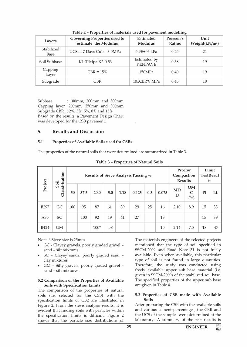
The comparison of the properties of natural soils (i.e. selected for the CSB) with the specification limits of CB2 are illustrated in Figure 2. From the sieve analysis results, it is evident that finding soils with particles within the specification limits is difficult. Figure 2 shows that the particle size distributions of natural soils are much closer to the upper limit of the specification (finer gradation).
The materials engineers of the selected projects mentioned that the type of soil specified in SSCM-2009 and Road Note 31 is not freely available. Even when available, this particular type of soil is not found in large quantities. Therefore, the study was conducted using freely available upper sub base material (i.e. given in SSCM-2009) of the stabilized soil base. The specified properties of the upper sub base are given in Table 4. 5.3 Properties of CSB made with Available
Soils After preparing the CSB with the available soils and various cement percentages, the CBR and the UCS of the samples were determined at the laboratory. A summary of the test results is presented in Table 5.
Proj
ect
Soil
Cla
ssif
icat
ion Results of Sieve Analysis Passing %
Proctor Compaction
Results
Limit TestResul
ts
50 37.5 20.0 5.0 1.18 0.425 0.3 0.075 MDD
OMC
(%) PI LL
B297 GC 100 95 87 61 39 29 25 16 2.10 8.9 15 33
A35 SC 100 92 49 41 27 13 15 39
B424 GM 100* 58 15 2.14 7.5 18 47
ENGINEER25ENGINEER 4
To identify and develop a relationship between the cement content, CBR and UCS of a CSB
To identify a suitable method for measuring the strength of a CSB, i.e., CBR or UCS
To develop a pavement design chart for CSB pavements for various traffic and subgrade classes
4. Methodology 4.1 Determination of the Properties of
Available Soils used for CSBs The test reports pertaining to borrow pit samples of natural soils that were selected for the CSBs of the proposed rehabilitation road projects were collected and the properties of the soils were determined through standard laboratory tests. Thereafter, a soil classification was done as per the Unified Soil Classification System. [11]
4.2 Checking of the Properties of the Available Soils to see whether they are within the Specification Limits
According to SSCM-2009, CB2 is the finest material that can be used for cement stabilized bases. Therefore, sieve analysis tests were carried out to compare the properties of natural soils (i.e. selected for CSBs) with related specification limits of CB2. 4.3 Preparation of CSB Samples made with
Available Soils and the Determination of their Properties
A sample was collected from the Kalmadukulam Borrow pit of the A35 project. The Modified Proctor Test was carried out as per the standard given in AASHTO T-180 to ascertain the moisture – density relationship of the stabilized soil sample mixed with cement. A series of tests were done to ascertain the moisture – density relationships of the stabilized soil with its cement content ranging from 1.5% to 5.0% at 0.5% intervals. According to the guidelines given in Road Note 31, stabilized soil should be compacted to 97% of the Maximum Dry Density (MDD) and attain the Optimum Moisture Content (OMC) to form
a cement stabilized subbase (CSB). The MDD (97%) and the OMC of the stabilized soil were derived from the moisture–density relationship. The CBR and UCS test specimens of the stabilized soil were prepared for 97% compaction and 7 days of moisture curing and the prepared specimens were soaked in water for 7 days as per Road Note 31. After the curing, CBR and UCS tests were carried out on the specimens according to AASHTO T-193 and BS 1924 respectively.
4.4 Development of Relationships among the
Cement Content, CBR and UCS After obtaining the CBR and UCS values of the CSB with different cement proportions, SPSS software was used to determine the relationships among the three parameters, i.e., cement content, CBR and UCS. Thereafter, the relevant equations were derived using a fitted model. 4.5 Fatigue and Rutting Analysis and the
Estimation of the Traffic Demand on CSB Pavements
The CSB pavements with stabilized bases were modelled and analysed using KENPAVE mechanistic pavement design software provided with the book ‘Pavement Analysis and Design’ [6]. The estimated modulus and other properties used for pavement modelling were calculated using the equations given in the previous section (Equations 1, 2, and 3) and summarized in Table 2.
A single-axle standard load of 80 kN was applied on the molded pavement and the allowable number of repetitions for both fatigue cracking and permanent deformation (rutting) were calculated using Equations 4 and 5 respectively. This analysis was performed for 200mm and 175mm thicknesses of CSB with a 8% CBR of subgrade. 4.6 Development of the Pavement Design Chart A mechanistic pavement analysis was performed on various combinations of subbase, capping layer and subgrade CBR as indicated below: CSB base : 150mm, 175mm and 200mm
Table 2 – Properties of materials used for pavement modelling
Layers Governing Properties used to estimate the Modulus
Estimated Modulus
Poisson’s Ratios
Unit Weight(kN/m3)
Stabilized Base UCS at 7 Days Cub – 3.0MPa 5.9E+06 kPa 0.25 21
Soil Subbase K1-31Mpa K2-0.53 Estimated by KENPAVE 0.38 19
Capping Layer CBR = 15% 150MPa 0.40 19
Subgrade CBR 10xCBR% MPa 0.45 18
5 ENGINEER
Subbase : 100mm, 200mm and 300mm Capping layer :200mm, 250mm and 300mm Subgrade CBR : 2%, 3%, 5%, 8% and 15% Based on the results, a Pavement Design Chart was developed for the CSB pavement.
.
5. Results and Discussion 5.1 Properties of Available Soils used for CSBs The properties of the natural soils that were determined are summarized in Table 3.
Table 3 – Properties of Natural Soils
Note -* Sieve size is 25mm GC - Clayey gravels, poorly graded gravel –
sand – silt mixtures SC – Clayey sands, poorly graded sand –
clay mixtures GM – Silty gravels, poorly graded gravel –
sand – silt mixtures
5.2 Comparison of the Properties of Available Soils with Specification Limits
The comparison of the properties of natural soils (i.e. selected for the CSB) with the specification limits of CB2 are illustrated in Figure 2. From the sieve analysis results, it is evident that finding soils with particles within the specification limits is difficult. Figure 2 shows that the particle size distributions of natural soils are much closer to the upper limit of the specification (finer gradation).
The materials engineers of the selected projects mentioned that the type of soil specified in SSCM-2009 and Road Note 31 is not freely available. Even when available, this particular type of soil is not found in large quantities. Therefore, the study was conducted using freely available upper sub base material (i.e. given in SSCM-2009) of the stabilized soil base. The specified properties of the upper sub base are given in Table 4. 5.3 Properties of CSB made with Available
Soils After preparing the CSB with the available soils and various cement percentages, the CBR and the UCS of the samples were determined at the laboratory. A summary of the test results is presented in Table 5.
Proj
ect
Soil
Cla
ssif
icat
ion Results of Sieve Analysis Passing %
Proctor Compaction
Results
Limit TestResul
ts
50 37.5 20.0 5.0 1.18 0.425 0.3 0.075 MDD
OMC
(%) PI LL
B297 GC 100 95 87 61 39 29 25 16 2.10 8.9 15 33
A35 SC 100 92 49 41 27 13 15 39
B424 GM 100* 58 15 2.14 7.5 18 47
Table 2 – Properties of materials used for pavement modelling
Layers Governing Properties used to estimate the Modulus
Estimated Modulus
Poisson’s Ratios
Unit Weight(kN/m3)
Stabilized Base UCS at 7 Days Cub – 3.0MPa 5.9E+06 kPa 0.25 21
Soil Subbase K1-31Mpa K2-0.53 Estimated by KENPAVE 0.38 19
Capping Layer CBR = 15% 150MPa 0.40 19
Subgrade CBR 10xCBR% MPa 0.45 18
ENGINEER 26ENGINEER 6
Figure 2 – Particle size distribution of natural and specified soils
Table 4 – Specified upper subbase material BS test sieve Percentage by mass of total
passing test sieve mm µm 53 100
37.5 80 - 100 20 60 - 100 5 30 - 100
1.18 17 - 75
300 9 - 50
75 5 - 25 Maximum allowable value
LL 40 PI 15
Table 5 - UCS and CBR test results
Mixed Cement
% (By Dry
Weight of Soil)
Unconfined Compressive
Strength (MPa)
CBR % at 97% of MDD
1.5 0.3 190 2.0 0.6 205 2.5 2.1 235 3.0 2.4 210 3.5 2.7 275 4.0 2.9 235 4.5 3.6 215 5.0 4.0 220
MDD= Maximum Dry Density 5.4 Relationships of the CBR and the UCS
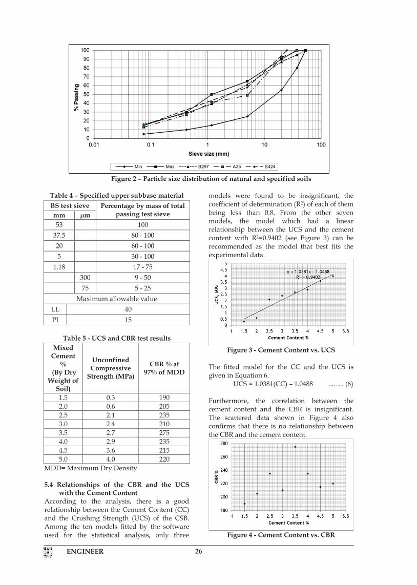
with the Cement Content According to the analysis, there is a good relationship between the Cement Content (CC) and the Crushing Strength (UCS) of the CSB. Among the ten models fitted by the software used for the statistical analysis, only three
models were found to be insignificant, the coefficient of determination (R2) of each of them being less than 0.8. From the other seven models, the model which had a linear relationship between the UCS and the cement content with R2=0.9402 (see Figure 3) can be recommended as the model that best fits the experimental data.
Figure 3 - Cement Content vs. UCS
The fitted model for the CC and the UCS is given in Equation 6.
UCS = 1.0381(CC) – 1.0488 ...….. (6)
Furthermore, the correlation between the cement content and the CBR is insignificant. The scattered data shown in Figure 4 also confirms that there is no relationship between the CBR and the cement content.
Figure 4 - Cement Content vs. CBR
7 ENGINEER
Figure 5 shows the plot of CBR and UCS values of the tested samples with different cement contents. Several models were fitted and none of the models gave a good correlation between CBR and UCS values.
Figure 5 - UCS vs. CBR
This analysis shows that the UCS of the CSB increases lineally as the Cement Content (CC)is increased. This increment is expected in the field. Despite the fact that some engineers and SSCM-1989 expect the CBR of the CSB to increase with the cement content, this study reveals that no such relationship exists between CBR and cement content as well as between CBR and USB. Therefore, the strength of the CSB should be measured using the UCS. 5.5 Results of Fatigue and Rutting Analysis The analysis was performed for various thicknesses of CSB. Tables 6 and 7 show the fatigue and rutting perfomance of CSB layers that are of 200mm and 175mm thickness
respectively. The subgrade CBR of the two data sets was 8%. According to the analysis, it was found that when the CSB thickness is increased from 175mm to 200mm, the allowable number of load repetitions for fatigue is increased by five times and that the allowable number of load repetitions for rutting is increased by two times. Therefore, the pavement design with a 200mm CSB can be considered as the most economical pavement design for a CSB made from available soils. Since the allowable number of load repetitions for rutting is always greater than that for fatigue, fatigue cracking would be more critical in a CSB pavement than rutting . 5.6 Pavement Design Chart developed for
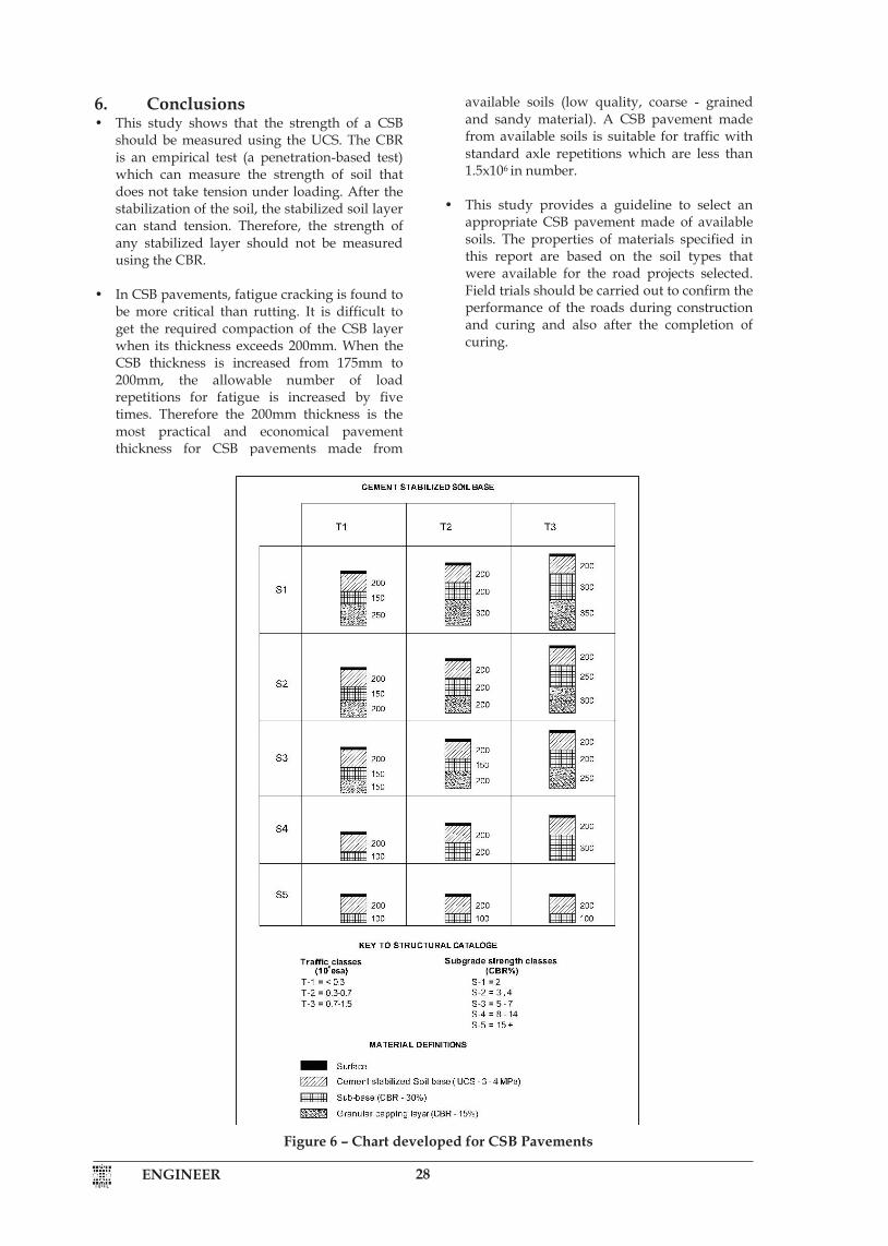
CSB Pavements The Pavement Design Chart prepared for various subgrades and traffic conditions based on the analysis is shown in Figure 6. The chart shows that CSB is suitable for traffic with less than 1.5x10⁶ standard axle repetitions. In the charts for cement stabilized roadbases given in Overseas Road Note 31, the maximum thickness allowed for a cement stabilized road base layer is 175 mm for the given traffic class (i.e. less than 1.5x10⁶). The maximum thickness allowed for the granular capping layer is 350 mm which is similar to what is provided in the chart developed in this study.
Table 6 – Fatigue and rutting analysis of 200mm thick CSB
Table 7 – Fatigue and rutting analysis of 175mm thick CSB
Sub Base Thickness
(mm)
Tensile Strain at Bottom
of CSB
Load Repetitions for
Fatigue
Compressive Strain at Top of Sub Grade
Load Repetitions for
Rutting
100 9.888 x 10⁻⁵ 6.084 x 10⁵ 2.469 x 10⁻⁴ 1.931 x 10⁷
200 9.256 x 10⁻⁵ 1.344 x 10⁶ 2.183 x 10⁻⁴ 3.351 x 10⁷
300 8.862 x 10⁻⁵ 2.265 x 10⁶ 1.873 x 10⁻⁴ 6.652 x 10⁷
Sub Base Thickness
(mm)
Tensile Strain at Bottom
of CSB
Load Repetitions for
Fatigue
Compressive Strain at Top of Sub Grade
Load Repetitions for
Rutting
100 1.154 x 10⁻⁴ 9.528 x 10⁴ 2.971 x 10⁻⁴ 8.432 x 10⁶
200 1.064 x 10⁻⁴ 2.524 x 10⁵ 2.585 x 10⁻⁴ 1.572 x 10⁷
300 1.013 x 10⁻⁴ 4.551 x 10⁵ 2.179 x 10⁻⁴ 3.379 x 10⁷

ENGINEER27ENGINEER 6
Figure 2 – Particle size distribution of natural and specified soils
Table 4 – Specified upper subbase material BS test sieve Percentage by mass of total
passing test sieve mm µm 53 100
37.5 80 - 100 20 60 - 100 5 30 - 100
1.18 17 - 75
300 9 - 50
75 5 - 25 Maximum allowable value
LL 40 PI 15
Table 5 - UCS and CBR test results
Mixed Cement
% (By Dry
Weight of Soil)
Unconfined Compressive
Strength (MPa)
CBR % at 97% of MDD
1.5 0.3 190 2.0 0.6 205 2.5 2.1 235 3.0 2.4 210 3.5 2.7 275 4.0 2.9 235 4.5 3.6 215 5.0 4.0 220
MDD= Maximum Dry Density 5.4 Relationships of the CBR and the UCS
with the Cement Content According to the analysis, there is a good relationship between the Cement Content (CC) and the Crushing Strength (UCS) of the CSB. Among the ten models fitted by the software used for the statistical analysis, only three
models were found to be insignificant, the coefficient of determination (R2) of each of them being less than 0.8. From the other seven models, the model which had a linear relationship between the UCS and the cement content with R2=0.9402 (see Figure 3) can be recommended as the model that best fits the experimental data.
Figure 3 - Cement Content vs. UCS
The fitted model for the CC and the UCS is given in Equation 6.
UCS = 1.0381(CC) – 1.0488 ...….. (6)
Furthermore, the correlation between the cement content and the CBR is insignificant. The scattered data shown in Figure 4 also confirms that there is no relationship between the CBR and the cement content.
Figure 4 - Cement Content vs. CBR
7 ENGINEER
Figure 5 shows the plot of CBR and UCS values of the tested samples with different cement contents. Several models were fitted and none of the models gave a good correlation between CBR and UCS values.
Figure 5 - UCS vs. CBR
This analysis shows that the UCS of the CSB increases lineally as the Cement Content (CC)is increased. This increment is expected in the field. Despite the fact that some engineers and SSCM-1989 expect the CBR of the CSB to increase with the cement content, this study reveals that no such relationship exists between CBR and cement content as well as between CBR and USB. Therefore, the strength of the CSB should be measured using the UCS. 5.5 Results of Fatigue and Rutting Analysis The analysis was performed for various thicknesses of CSB. Tables 6 and 7 show the fatigue and rutting perfomance of CSB layers that are of 200mm and 175mm thickness
respectively. The subgrade CBR of the two data sets was 8%. According to the analysis, it was found that when the CSB thickness is increased from 175mm to 200mm, the allowable number of load repetitions for fatigue is increased by five times and that the allowable number of load repetitions for rutting is increased by two times. Therefore, the pavement design with a 200mm CSB can be considered as the most economical pavement design for a CSB made from available soils. Since the allowable number of load repetitions for rutting is always greater than that for fatigue, fatigue cracking would be more critical in a CSB pavement than rutting . 5.6 Pavement Design Chart developed for
CSB Pavements The Pavement Design Chart prepared for various subgrades and traffic conditions based on the analysis is shown in Figure 6. The chart shows that CSB is suitable for traffic with less than 1.5x10⁶ standard axle repetitions. In the charts for cement stabilized roadbases given in Overseas Road Note 31, the maximum thickness allowed for a cement stabilized road base layer is 175 mm for the given traffic class (i.e. less than 1.5x10⁶). The maximum thickness allowed for the granular capping layer is 350 mm which is similar to what is provided in the chart developed in this study.
Table 6 – Fatigue and rutting analysis of 200mm thick CSB
Table 7 – Fatigue and rutting analysis of 175mm thick CSB
Sub Base Thickness
(mm)
Tensile Strain at Bottom
of CSB
Load Repetitions for
Fatigue
Compressive Strain at Top of Sub Grade
Load Repetitions for
Rutting
100 9.888 x 10⁻⁵ 6.084 x 10⁵ 2.469 x 10⁻⁴ 1.931 x 10⁷
200 9.256 x 10⁻⁵ 1.344 x 10⁶ 2.183 x 10⁻⁴ 3.351 x 10⁷
300 8.862 x 10⁻⁵ 2.265 x 10⁶ 1.873 x 10⁻⁴ 6.652 x 10⁷
Sub Base Thickness
(mm)
Tensile Strain at Bottom
of CSB
Load Repetitions for
Fatigue
Compressive Strain at Top of Sub Grade
Load Repetitions for
Rutting
100 1.154 x 10⁻⁴ 9.528 x 10⁴ 2.971 x 10⁻⁴ 8.432 x 10⁶
200 1.064 x 10⁻⁴ 2.524 x 10⁵ 2.585 x 10⁻⁴ 1.572 x 10⁷
300 1.013 x 10⁻⁴ 4.551 x 10⁵ 2.179 x 10⁻⁴ 3.379 x 10⁷
ENGINEER 28ENGINEER 8
6. Conclusions • This study shows that the strength of a CSB
should be measured using the UCS. The CBR is an empirical test (a penetration-based test) which can measure the strength of soil that does not take tension under loading. After the stabilization of the soil, the stabilized soil layer can stand tension. Therefore, the strength of any stabilized layer should not be measured using the CBR.
• In CSB pavements, fatigue cracking is found to
be more critical than rutting. It is difficult to get the required compaction of the CSB layer when its thickness exceeds 200mm. When the CSB thickness is increased from 175mm to 200mm, the allowable number of load repetitions for fatigue is increased by five times. Therefore the 200mm thickness is the most practical and economical pavement thickness for CSB pavements made from
available soils (low quality, coarse - grained and sandy material). A CSB pavement made from available soils is suitable for traffic with standard axle repetitions which are less than 1.5x10⁶ in number.
• This study provides a guideline to select an
appropriate CSB pavement made of available soils. The properties of materials specified in this report are based on the soil types that were available for the road projects selected. Field trials should be carried out to confirm the performance of the roads during construction and curing and also after the completion of curing.
Figure 6 – Chart developed for CSB Pavements
9 ENGINEER
Acknowledgements Authors wish to acknowledge the assistance they received from the Highway and Transportation Division of the University of Moratuwa through the provision of all required equipment and support for carrying out the experiments. References 1. Little, D. N., Nair, S., 2009, Recommended
Practice for Stabilization of Subgrade Soils and Base Materials, National Cooperative Highway Research Program (NCHRP), Web only document – 144, Texas A&M University, Texas.
2. Ingles, O. G, Metcalf, J. B., 1972. Soil stabilization:
principles and practice. Sydney: Butterworth. 3. Arellano, D., Thompson, M. R. 1998.Final report -
Stabilized base properties (strength, modulus, fatigue) for mechanistic-based airport pavement design, Technical Report of Research, Department of civil engineering University of Illinois at Urbana-Champaign, Illinois,.
4. Standard Specification for Construction and
Maintenance of Road and Bridges (SSCM), Road Development Authority (RDA), 1989
5. Croney, D., Croney, P., 1998, The Design and
Performance of Road Pavements. 3rd Edition, Published by McGraw-Hill, UK.
6. Yang, H. H., 2004, Pavement Analysis and
Design, 2nd Edition, ISBN 0131424734 9780131424739.
7. Technical Basis of Austroads Pavement Design
Guide, TP-T33, 2011United Kingdom Road Note 31, Transport & Road Research Laboratory, 1977
8. Lilley, A. A., 1973, Cement-Stabilized Materials in
Great Britain, Record 442, Highway Research Board.
9. Asphalt Institute, (1982). Introduction to asphalt.
[8th ed.] College Park, Md. (Asphalt Institute Building, College Park 20740 USA): Asphalt Institute.
10. Standard Specification for Construction and
Maintenance of Road and Bridges (SSCM), Institute for Construction Training and Development (ICTAD), 2nd Edition, 2009
11. Wagner, A. A., 1957, The use of unified soils
classification system by Bureau of Reclamation. 4th ICSMFE, London.
ENGINEER 8
6. Conclusions • This study shows that the strength of a CSB
should be measured using the UCS. The CBR is an empirical test (a penetration-based test) which can measure the strength of soil that does not take tension under loading. After the stabilization of the soil, the stabilized soil layer can stand tension. Therefore, the strength of any stabilized layer should not be measured using the CBR.
• In CSB pavements, fatigue cracking is found to
be more critical than rutting. It is difficult to get the required compaction of the CSB layer when its thickness exceeds 200mm. When the CSB thickness is increased from 175mm to 200mm, the allowable number of load repetitions for fatigue is increased by five times. Therefore the 200mm thickness is the most practical and economical pavement thickness for CSB pavements made from
available soils (low quality, coarse - grained and sandy material). A CSB pavement made from available soils is suitable for traffic with standard axle repetitions which are less than 1.5x10⁶ in number.
• This study provides a guideline to select an
appropriate CSB pavement made of available soils. The properties of materials specified in this report are based on the soil types that were available for the road projects selected. Field trials should be carried out to confirm the performance of the roads during construction and curing and also after the completion of curing.
Figure 6 – Chart developed for CSB Pavements

ENGINEER29ENGINEER 8
6. Conclusions • This study shows that the strength of a CSB
should be measured using the UCS. The CBR is an empirical test (a penetration-based test) which can measure the strength of soil that does not take tension under loading. After the stabilization of the soil, the stabilized soil layer can stand tension. Therefore, the strength of any stabilized layer should not be measured using the CBR.
• In CSB pavements, fatigue cracking is found to
be more critical than rutting. It is difficult to get the required compaction of the CSB layer when its thickness exceeds 200mm. When the CSB thickness is increased from 175mm to 200mm, the allowable number of load repetitions for fatigue is increased by five times. Therefore the 200mm thickness is the most practical and economical pavement thickness for CSB pavements made from
available soils (low quality, coarse - grained and sandy material). A CSB pavement made from available soils is suitable for traffic with standard axle repetitions which are less than 1.5x10⁶ in number.
• This study provides a guideline to select an
appropriate CSB pavement made of available soils. The properties of materials specified in this report are based on the soil types that were available for the road projects selected. Field trials should be carried out to confirm the performance of the roads during construction and curing and also after the completion of curing.
Figure 6 – Chart developed for CSB Pavements
9 ENGINEER
Acknowledgements Authors wish to acknowledge the assistance they received from the Highway and Transportation Division of the University of Moratuwa through the provision of all required equipment and support for carrying out the experiments. References 1. Little, D. N., Nair, S., 2009, Recommended
Practice for Stabilization of Subgrade Soils and Base Materials, National Cooperative Highway Research Program (NCHRP), Web only document – 144, Texas A&M University, Texas.
2. Ingles, O. G, Metcalf, J. B., 1972. Soil stabilization:
principles and practice. Sydney: Butterworth. 3. Arellano, D., Thompson, M. R. 1998.Final report -
Stabilized base properties (strength, modulus, fatigue) for mechanistic-based airport pavement design, Technical Report of Research, Department of civil engineering University of Illinois at Urbana-Champaign, Illinois,.
4. Standard Specification for Construction and
Maintenance of Road and Bridges (SSCM), Road Development Authority (RDA), 1989
5. Croney, D., Croney, P., 1998, The Design and
Performance of Road Pavements. 3rd Edition, Published by McGraw-Hill, UK.
6. Yang, H. H., 2004, Pavement Analysis and
Design, 2nd Edition, ISBN 0131424734 9780131424739.
7. Technical Basis of Austroads Pavement Design
Guide, TP-T33, 2011United Kingdom Road Note 31, Transport & Road Research Laboratory, 1977
8. Lilley, A. A., 1973, Cement-Stabilized Materials in
Great Britain, Record 442, Highway Research Board.
9. Asphalt Institute, (1982). Introduction to asphalt.
[8th ed.] College Park, Md. (Asphalt Institute Building, College Park 20740 USA): Asphalt Institute.
10. Standard Specification for Construction and
Maintenance of Road and Bridges (SSCM), Institute for Construction Training and Development (ICTAD), 2nd Edition, 2009
11. Wagner, A. A., 1957, The use of unified soils
classification system by Bureau of Reclamation. 4th ICSMFE, London.