cement chemistry 2nd edition
TRANSCRIPT


Cement chemistry
2nd edition
H.F.W. TaylorEmeritus Professor of Inorganic ChemistryUniversity of Aberdeen
ThomasTelford

Published by Thomas Telford Publishing, Thomas Telford Services Ltd,1 Heron Quay, London E144JD
First published 1990 by Academic PressThomas Telford edition published 1997
Distributors for Thomas Telford books areUSA: American Society of Civil Engineers, Publications Sales Department,345 East 47th Street, New York, NY 10017-2398Japan: Maruzen Co. Ltd, Book Department, 3A10 Nihonbashi 2-chome, Chuo-ku, Tokyo 103Australia: DA Books and Journals, 648 Whitehorse Road, Mitcham 3132, Victoria
A catalogue record for this book is available from the British Library
ISBN: 0 7277 2592 0
© Professor H.F.W. Taylor and Thomas Telford Services Ltd, 1997
All rights, including translation, reserved. Except for fair copying, no part of thispublication may be reproduced, stored in a retrieval system or transmitted in any form or byany means, electronic, mechanical, photocopying or otherwise, without the prior permissionof the Books Publisher, Thomas Telford Publishing, Thomas Telford Services Ltd, 1 HeronQuay, London E144JD.
This book is published on the understanding that the author is solely responsible for thestatements made and opinions expressed in it and that its publication does not necessarilyimply that such statements and/or opinions are or reflect the views or opinions of thepublishers.
Preface
The previous edition of this book, published by Academic Press in 1990,is both out of print and out of date, and when Thomas Telford invited meto prepare a new edition I was delighted to comply. I am most gratefulboth to them and to Academic Press, whose release of the copyright madethe present edition possible.
This book deals with the chemistry of the principal silicate andaluminate cements used in building and civil engineering. It is directedprimarily to those whose background is in chemistry, materials science orrelated disciplines. Emphasis is placed throughout on the underlyingscience rather than on practical applications, which are well covered inother works. The cements considered fall into the category of hydrauliccements; they set and harden as a result of chemical reactions with water,and if mixed with water in appropriate proportions continue to hardeneven if subsequently placed in water. Much the most important is Portlandcement. Chapters 1 to 4 deal mainly with the chemistry of Portland cementmanufacture and the nature of the resulting product. Chapters 5 to 8 dealmainly with the processes that occur when this product is mixed withwater and with the nature of the hardened material. Chapters 9 to 11 dealwith the chemistry of other types of cement, of admixtures for concreteand of special uses for cements. Chapter 12 deals with chemical and micro-structural aspects of concrete, including ones that affect its durability orlimit its service life.
The literature of cement chemistry is voluminous; the abstractingjournal, Cements Research Progress, has for some years listed around1000 new contributions annually. The output of the seven years since theprevious edition of this book appeared is reflected in the increasednumber of references to the literature, which is approximately 1500compared with 1300 in that edition. Of necessity, coverage in the presentbook has been selective, but it is hoped that the most importantcontributions up to mid-1996 have been covered. The advances in someparts of the subject have been greater than in others, and this is reflectedin the differences between this and the previous edition; some sectionshave been totally rewritten whereas others have changed relatively little.
As one who has seen the subject develop over a period of nearly 50years, I am highly aware of the problems that those entering the subject
iii

Cement chemistry
for the first time have in grappling with the previous literature. I havetherefore tried not only to deal with recent research, but also to place thedevelopment of our knowledge in a historical perspective. I hope that thebook will thereby serve both as an introduction that assumes no previousspecialist knowledge of cements, and as a guide to further research.
AcknowledgementsI am most grateful to Sally Smith and her colleagues at Thomas TelfordPublishing for their unfailing help and patience, and to my wife, Joan, forhelp in preparing the reference list and in other ways. I am also mostgrateful to former colleagues at the University of Aberdeen and friendselsewhere with whom I have had productive discussions over a period ofmany years. Professor F.P. Glasser was most helpful in suggesting thatthis edition be published. Others in Aberdeen to whom thanks are dueinclude, notably, Dr J.A. Gard, Dr L.S. (Dent) Glasser and Dr E.E.Lachowski. Either indirectly through the previous edition, or directly inrelation to the present one, many others have given invaluable assistance.Mr R.S. Gollop, Dr S. Kelham, Mr C.P. Kerton, Dr G.R. Long, Mr J.S.Lumley, Dr J.J. Kollek, Dr G.K. Moir and Mr M.S. Sumner, now orformerly of Blue Circle Industries pic, helped on many aspects of cementproduction, use and durability. My thoughts on the hydration chemistryof calcium silicates owe much to discussions with Drs P.W. Brown,G. Frohnsdorff and H.M. Jennings, then all at the National Bureau ofStandards (now NIST), USA. Those on microstructural aspects of hydra-tion similarly owe much to discussions with the late Professor P.L. Prattand Dr K.L. Scrivener, then both at Imperial College, London. Dr L.J.Parrott (British Cement Association) helped greatly with a discussion onthe pore structures of cement pastes. Drs A. Capmas, C M . George, K.L.Scrivener, D. Sorrentino and F. Sorrentino (Lafarge Corporation) gaveextensive and invaluable help in preparing the section on calciumaluminate cements. Professor J. Bensted, then at The British PetroleumCompany pic, corrected some important errors on oil well cementing.Many of those mentioned above gave help that included comments onparts of the manuscript, but any errors are mine.
Many people, noted in the reference list, generously made resultsavailable in advance of publication. Dr D.C. Pomeroy, formerly at theBritish Cement Association, Drs K.L. Scrivener and M.C. Lewis(Imperial College) and Dr D. Sorrentino kindly provided some excellentlight or electron micrographs. Mr C.P. Kerton freely gave extensivebibliographical assistance, and I thank Mr S. Black and Ms J. Kerr(University of Aberdeen) for photography of the line drawings.
I thank publishers (as copyright holders; italics) and authors for permission toreproduced the figures noted below. Authors and sources, including copyrightyears, are given in the captions and reference list and, where it was requested, theacknowledgment is expanded below. Reprinted by permission of the AmericanCeramic Society, Figs 5.5C and D (Ref. J l l , Issue 10, Oct., on 'Morphologicaldevelopment of hydrating tricalcium silicate as examined by electron micro-scopy techniques'); Fig. 5.1 (Ref. M46, Issue 12, Dec, on 'Analytical electron
iv

Preface
microscopy of cement pastes: IV, /3-dicalcium silicate pastes'); Figs 5.7 and 5.9(Ref. T21, Issue 6, June, on 'Proposed structure for calcium silicate hydrate gel');Fig. 5.12 (Ref. J16, Issue 8, Aug., on 'Aqueous solubility relationships for twotypes of calcium silicate hydrate'); Fig. 9.3 (Ref. T39, Issue 12, Dec, on'Analytical study of pure and extended Portland cement pastes: II, fly ash- andslag-cement pastes'). American Concrete Institute, Fig. 11.6. Reprinted bypermission of American Journal of Science, Fig. 6.5. British Cement Association,Fig. 5.11. © (British) Crown Copyright 1970. Published by permission of theController of HMSO, and with thanks to the Institute of Materials, Fig. 2.9.Cemento, Fig. 11.4. Chapman and Hall Ltd, Figs 10.2 and 10.6. Reprinted from'Cement and Concrete Research', with kind permission from Elsevier Science Ltd,The Boulevard, Langford Lane, Kidlington 0X5 1GB, UK, Figs 1.2, 3.3, 5.4, 5.8,5.14, 5.15, 8.9, 11.1, 11.5, 12.5 and 12.7. International Cement MicroscopyAssociation from 'Proceedings of the 6th International Conference on CementMicroscopy, Albuquerque, NM, USA', Fig. 4.3. 8th International Congress on theChemistry of Cement (Vol. 3, Fig. 4, p. 231), Fig. 6.7. Materials Research Society,Figs 9.1, 9.2 and 12.1. R. Oldenbourg Verlag, Fig. 5.6. Palladian Publications Ltd.,Fig. 7.1. RILEM Publications, first published in 'The hydration of tricalciumsilicate', RILEM committee 68-MMH, task group 3, 'Materials and Structures'17, (102) 458 (1984), Figs 5.10 and 5.13. The Royal Society, Fig. 7.7. EditionsSeptima, Fig. 10.7. Society of Chemical Industry, Fig. 5.2. Stroyizdat, Fig. 3.4.Thomas Telford Publishing, Figs 12.4 and 12.6. Transportation Research Board,National Research Council, Washington, DC, Fig. 4, p. 380 in Ref. L35, 'Changesin composition of the aqueous phase during hydration of cement pastes andsuspensions', Fig. 7.8. Reprinted by permission of John Wiley and Sons Ltd, Fig.8.4. I thank the National Bureau of Standards (now NIST) for the use of Figs 7.9and 8.2. Figs 7.2, 8.8, 10.1, 11.3, 12.2, 12.3, 12.7, 12.8 and 12.9 did not appear inthe previous edition of this book. The remaining figures were used in that edition,and I am most grateful to Academic Press for permission to reproduce them.

Contents
1 Portland cement and its major constituent phases 11.1 Introduction 11.1.1 Portland cement: general 11.1.2 Types of Portland cement 21.1.3 Cement chemical nomenclature and other abbreviations 3
1.2 Alite 41.2.1 Polymorphism and crystal structure 41.2.2 Tricalcium silicate solid solutions 71.2.3 Compositions of alites in clinkers 71.2.4 Polymorphic modifications of the alites in clinkers 91.2.5 X-ray powder patterns and densities of tricalcium silicate
and alites 121.2.6 Optical, thermal and other data 13
1.3 Belite 131.3.1 Polymorphism and crystal structure 131.3.2 Polymorphic forms and textures in clinker belites 161.3.3 Compositions of belites in clinkers 181.3.4 Cell parameters, X-ray powder patterns and other data 18
1.4 Aluminate 191.4.1 Crystal structure: cubic, orthorhombic and monoclinic
modifications 191.4.2 Other modifications 211.4.3 Structural modifications of clinker aluminates 221.4.4 Compositions of clinker aluminates 231.4.5 X-ray powder data, densities and optical properties 24
7.5 Ferrite 241.5.1 Crystal structure and composition in the
Ca2(AlJCFei_JC)2O5 series 241.5.2 Compositions of clinker ferrites 261.5.3 Crystal data and X-ray powder patterns for ferrites
containing substituent ions 271.5.4 Optical, magnetic and other data 28
vii

Cement chemistry
2 High-temperature chemistry 292.1 Introduction 29
2.2 Systems containing CaO with SiO2 or A12O3 or both 292.2.1 The CaO-SiO2 system 292.2.2 The CaO-Al2O3 system 302.2.3 Ci2A7 and derived structures 312.2.4 C5A3, C2A and C4A3 332.2.5 The CaO-Al2O3-SiO2 system 332.2.6 Clinker formation in the CaO-Al2O3-SiO2 system 35
2.3 Systems containing Fe2O3 362.3.1 The CaO-Al2O3-Fe2O3 system 362.3.2 The CaO-Al2O3-Fe2O3-SiO2 system 382.3.3 Clinker formation in the CaO-Al2O3-Fe2O3-SiO2 system 40
2.4 Systems containing MgO or FeO 422.4.1 General 422.4.2 Effect of MgO on equilibria in the
CaO-Al2O3-Fe2O3-SiO2 system 432.4.3 Phases structurally related to gehlenite 45
2.5 Systems containing alkalis or SO3 or both 462.5.1 Phases 462.5.2 Equilibria 49
2.6 Systems with other components 502.6.1 Fluorides and fluorosilicates 502.6.2 Carbonates 52
2.7 Laboratory preparation of high-temperature phases 52
3 The chemistry of Portland cement manufacture 553.1 General considerations 553.1.1 Summary of the reactions in clinker formation 553.1.2 Lime saturation factor, silica ratio and alumina ratio 563.1.3 The Bogue calculation 573.1.4 Enthalpy changes in clinker formation 58
3.2 Raw materials and manufacturing processes 603.2.1 Raw materials and fuel 603.2.2 Dry and wet processes; energy requirements 613.2.3 The dry process; suspension preheaters and precalciners 613.2.4 The rotary kiln 633.2.5 Circulation of volatiles; dust; cooling of clinker 643.2.6 Other processes for clinker production; clinker grinding 64
Contents
3.3 Reactions below about 1300°C 653.3.1 Decomposition of carbonate minerals 653.3.2 Decomposition of clay minerals and formation of products 663.3.3 Sampling from cement kilns or preheater outlets 673.3.4 Reaction mechanisms 683.3.5 Condensation or reaction of volatiles 69
3.4 Reactions at 1300-1450°C 703.4.1 Quantity of liquid formed 703.4.2 Burnabilities of raw mixes 723.4.3 Nodulization 743.4.4 Formation and recrystallization of alite 743.4.5 Evaporation of volatiles; polymorphic transitions 753.4.6 Effects of reducing conditions; colour of clinker 76
3.5 Reactions during cooling, grinding or storage 113.5.1 Solidification of the clinker liquid: indications from
pure systems 773.5.2 Do Portland cement clinkers contain glass or C12A7? 773.5.3 Evidence from X-ray microanalysis 793.5.4 Effects of cooling rate on the aluminate and ferrite phases 793.5.5 Other effects of cooling rate 803.5.6 Crystallization of the sulfate phases 813.5.7 Quantitative estimation of the distributions of alkalis and
SO3 between phases 813.5.8 Changes during grinding or storage 84
3.6 Effects of minor components 843.6.1 General 843.6.2 Effects of s-block elements 853.6.3 Effects of p- and d-block elements 86
4 Properties of Portland clinker and cement 894.1 Macroscopic and surface properties 894.1.1 Unground clinker 894.1.2 Particle size distribution of ground clinker or cement 894.1.3 Specific surface area determination 914.1.4 Particle size distribution, phase composition and
cement properties 924.1.5 Chemical analysis 93
4.2 Light microscopy 934.2.1 General 934.2.2 Effects of bulk composition, raw feed preparation and
ash deposition 954.2.3 Effects of burning conditions and cooling rate 954.2.4 Applications of light microscopic investigations 96
IX

Cement chemistry
4.3 Scanning electron microscopy, X-ray diffraction andother techniques 97
4.3.1 Scanning electron microscopy 974.3.2 X-ray diffraction 994.3.3 Chemical or physical methods for separation of phases 1004.3.4 Other methods 102
4.4 Calculation of quantitative phase composition frombulk chemical analysis 102
4.4.1 General 1024.4.2 Modified Bogue calculation 1024.4.3 Mass balance calculations 1044.4.4 Limitations and modifications of the modified
Bogue calculation 104
4.5 Physical methods for determining quantitativephase composition 106
4.5.1 General 1064.5.2 Light microscopy 1064.5.3 Quantitative X-ray diffraction analysis (QXDA) 1064.5.4 Comparison of results of different methods 108
4.6 Reactivities of clinker phases 1094.6.1 Effect of major compositional variation 1094.6.2 Effects of ionic substitutions, defects and variation
in polymorph 1104.6.3 Ferrite reactivity; effect of complexing in solution 112
5 Hydration of the calcium silicate phases 1135.7 Introduction 1135.1.1 Definitions and general points 1135.1.2 Experimental considerations; carbonation 1145.1.3 Calcium hydroxide 116
5.2 Composition, density and other data for C-S-H gel 1185.2.1 Calcium hydroxide content, thermal analysis and indirect
determination of the Ca/Si ratio 1185.2.2 Water content 1195.2.3 Density and infrared spectra 121
5.3 Microstructure, microanalysis and electron diffraction 1235.3.1 Microstructure 1235.3.2 Stages in micro structural development 1235.3.3 X-ray microanalysis 1265.3.4 Analytical electron microscopy 1275.3.5 Electron diffraction 128

Contents
5.4 More highly ordered phases related to C-S-H gel 1285.4.1 General 1285.4.2 l-4nm tobermorite 1295.4.3 Jennite 1315.4.4 C-S-H(I) 1325.4.5 Products formed in suspensions from C3S or
/?-C2S; C-S-H(II) 133
5.5 Silicate anion structure 1345.5.1 Introduction 1345.5.2 C-S-H gel of calcium silicate or cement pastes:
chemical methods 1355.5.3 C-S-H gel of calcium silicate or cement pastes: nuclear
magnetic resonance 1375.5.4 C-S-H(I) and other products made in suspension 138
5.6 The nanostructures of C-S-H gel and related materials 1405.6.1 Broad features and tobermorite-based models
for C-S-H(I) 1405.6.2 Tobermorite-based models for the C-S-H of calcium
silicate and cement pastes 1415.6.3 A mixed tobermorite-jennite model for the C-S-H of
calcium silicate and cement pastes 1425.6.4 Other models for the C-S-H of calcium silicate and
cement pastes 144
5.7 Equilibria 1455.7.1 Solubility relations 1455.7.2 Species in solution 1475.7.3 Thermochemistry and thermodynamics 1485.7.4 Effects of alkalis and of gypsum 149
5.8 Kinetics and mechanisms 1505.8.1 C3S: experimental data 1505.8.2 C3S: the initial reaction 1535.8.3 C3S: the induction period 1535.8.4 The main reaction (C3S and /?-C2S) 1555.8.5 Early hydration of (3-C2S 156
6 Hydrated aluminate, ferrite and sulfate phases 1576.1 AFm phases 1576.1.1 Compositional and structural principles 1576.1.2 The C4AHX, C4AC05Hx and C4ACHX phases 1596.1.3 The C4ASHX phases 1616.1.4 Other AFm phases containing aluminium 1616.1.5 AFm phases containing iron 1646.1.6 XRD patterns, thermal behaviour, optical properties
and IR spectra 164
XI

Cement chemistry
6.2 AFt phases 1666.2.1 Compositions and crystal structures 1666.2.2 Ettringite analogues and solid solutions 1686.2.3 Properties 169
6.3 Other hydrated phases 1706.3.1 Hydrogarnet phases 1706.3.2 CAH10 1716.3.3 Brucite, hydrotalcite and related phases 1736.3.4 Sulfate phases 174
6.4 Equilibria and preparative methods 1766.4.1 The CaSO4-H2O, CaSO4-Ca(OH)2-H2O and
CaSO4-K2SO4-H2O systems 1766.4.2 The CaO-Al2O3-H2O and CaO-Al2O3-SO3-H2O systems 1776.4.3 Systems including Na2O, K2O, SiO2, CaCO3 or CaCl2 1806.4.4 Preparative methods 181
6.5 Hydration reactions of the aluminate and ferrite phases 1826.5.1 Reaction of C3A with water or with water and
calcium hydroxide 1826.5.2 Reaction of C3A with water in the presence of
calcium sulfate 1826.5.3 Effects of temperature, alkali, tricalcium silicate and CO2 1846.5.4 Reaction of the ferrite phase 1846.5.5 Enthalpy changes 186
7 Hydration of Portland cement 1877.1 Evidence from X-ray diffraction, thermal analysis and
infrared spectroscopy 1877.1.1 Introduction; formation of calcium hydroxide and C-S-H 1877.1.2 Formation of hydrated aluminate or sulfoaluminate phases 1887.1.3 Evidence from differential thermal analysis and
infrared spectroscopy 189
7.2 Micro structure 1917.2.1 Evidence from light and electron microscopy 1917.2.2 The early period of hydration 1937.2.3 The middle period of hydration 1957.2.4 The late period of hydration 196
73 Analytical data for cement pastes 1977.3.1 Unreacted clinker phases 1977.3.2 Non-evaporable and bound water 1977.3.3 Thermogravimetry and calcium hydroxide content 1997.3.4 Hydrated aluminate and silicate phases 2017.3.5 Analyses of individual phases 2017.3.6 Silicate anion structure 204
XII

Contents
7.4 Interpretation of analytical data 2057.4.1 Substitution or admixed phases? 2057.4.2 Fe2O3 in cement hydration products 2077.4.3 MgO, SO3 and alkalis in cement hydration products 2087.4.4 The stoichiometry of cement hydration 209
7.5 Calorimetry, pore solutions and energetics 2127.5.1 The early and middle periods 2127.5.2 Pore solutions after the first day 2147.5.3 Energetics of cement hydration 215
7.6 Actions of calcium sulfate and of alkalis 2187.6.1 Setting 2187.6.2 Optimum gypsum 2197.6.3 Effects of alkalis 221
7.7 Kinetics and modelling of the hydration process 2227.7.1 Experimental data 2227.7.2 Interpretation of kinetic data 224
8 Structure and properties of fresh and hardened Portlandcement pastes 227
8.1 Fresh pastes 2278.1.1 Workability 2278.1.2 Rheology; viscometry 2278.1.3 Oscillatory and controlled-stress rheometry 2298.1.4 Models of fresh paste structure 230
8.2 Hardened cement pastes; models of structure 2318.2.1 The Powers-Brownyard model 2318.2.2 Minimum water/cement ratio for complete hydration;
chemical shrinkage 2328.2.3 Calculation of volumetric quantities 2348.2.4 Later models of cement gel structure 235
8.3 Mathematical modelling of micro structure and properties 2378.3.1 Introduction 2378.3.2 Calculation of porosities and of volume fractions of
solid phases 2388.3.3 Microstructural models 242
8.4 Experimental methods for studying pore structure 2438.4.1 General points 2438.4.2 Determination of porosities by pyknometry 2438.4.3 Sorption isotherms; specific surface areas 2448.4.4 Pore size distributions 2468.4.5 Mercury intrusion porosimetry (MIP) 2478.4.6 Scanning electron microscopy 2498.4.7 AC impedance spectroscopy 2498.4.8 Other methods 251
X I I I

Cement chemistry
8.5 Strength 2528.5.1 Empirical relations between compressive strength
and porosity 2528.5.2 Relations between strength and microstructure or pore
size distribution 2538.5.3 Mechanisms of failure 255
8.6 Deformation 2558.6.1 Modulus of elasticity 2558.6.2 Creep and shrinkage 256
8.7 Permeability and diffusion 2588.7.1 Permeability to water 2588.7.2 Diffusion of ions and gases 259
9 Composite cements 2619.1 Introduction 261
9.2 Blastfurnace slag 2629.2.1 Formation, treatment and use in composite cements 2629.2.2 Factors affecting suitability for use in a composite cement 2639.2.3 X-ray diffraction and microstructure of slags 2649.2.4 Internal structures of slag glasses 2659.2.5 Hydration chemistry of slag cements 2669.2.6 X-ray microanalysis 2679.2.7 Stoichiometry of slag cement hydration 2709.2.8 Activation of slag glasses 2719.2.9 Alkali-activated slag cements 2719.2.10 Supersulfated cements 272
9.3 Flyash (pulverized fuel ash) low in CaO 2729.3.1 Properties 2729.3.2 Factors governing suitability for use in composite cements 2749.3.3 Rates of consumption of clinker phases and flyash,
and contents of calcium hydroxide 2759.3.4 Microstructure and compositions of the hydration products 2779.3.5 Stoichiometry of flyash cement hydration 2799.3.6 The nature of the pozzolanic reaction 280
9.4 Natural pozzolanas 2809.4.1 Properties 2809.4.2 Hydration reactions 281
9.5 Silica fume (condensed silica fume, microsilica) 2849.5.1 Properties 2849.5.2 Hydration reactions 285
XIV

Contents
9.6 Other mineral additions 2869.6.1 Class Cflyash 2869.6.2 Other pozzolanic or hydraulic additions 2889.6.3 Calcium carbonate and other mineral additions 289
9.7 Pore structures and their relation to physical properties 2909.7.1 Calculated porosities for pastes containing slag or flyash 2909.7.2 Modelling of pore structure 2909.7.3 Experimental determination of porosities and pore
size distributions 2919.7.4 Relations between pore structure and physical properties 293
10 Calcium aluminate, expansive and other cements 29510.1 Calcium aluminate cements 29510.1.1 Introduction 29510.1.2 Manufacture; chemical and mineralogical compositions 29510.1.3 Reactivities of the phases and methods of
studying hydration 29810.1.4 Hydration reactions and products 29810.1.5 Thermodynamic calculations 30110.1.6 Setting times; mixing and placing 30310.1.7 Microstructural development 30410.1.8 Hardening; effects of conversion 30610.1.9 Chemical admixtures 30910.1.10 Mixtures with calcite, slag, gypsum or Portland cement 31010.1.11 Reactions of calcium aluminate cement concrete
with external agents 31110.1.12 Refractory castables 312
10.2 Expansive cements 31310.2.1 General 31310.2.2 Types of expansive cement 31410.2.3 Mechanism of expansion in Type K cements 315
10.3 Other cements 31710.3.1 Very rapidly hardening cements 31710.3.2 Energy reduction in the manufacture of cements 31910.3.3 Reactive belites 32010.3.4 Cements containing belite and a highly reactive
constituent 32110.3.5 Alinite cements 321
11 Admixtures and special uses of cements 32311.1 Introduction 323
11.2 Organic retarders and accelerators 32311.2.1 Retarders 32311.2.2 Mechanism of retardation 32411.2.3 Practical retarders 32711.2.4 Organic accelerators 328

Cement chemistry
11.3 Air-entraining agents and grinding aids 32811.3.1 Air-entraining agents 32811.3.2 Grinding aids 329
11.4 Water reducers and super'plasticizers 33011.4.1 Water reducers 33011.4.2 Superplasticizers 33011.4.3 Mode of action of water reducers and superplasticizers 33211.4.4 Zeta potential, rheology and nature of the sorbent phases 33311.4.5 Reasons for the enhanced dispersing power of
superplasticizers 334
11.5 Inorganic accelerators and retarders 33411.5.1 Accelerators of setting and hardening 33411.5.2 Mode of action 33511.5.3 Effects on the composition and structure of the
hydration products 33711.5.4 Precipitation effects; inorganic retarders and setting
accelerators 338
11.6 Effects of high or low temperatures at atmospheric pressure 33911.6.1 Hydration at 25-100°C 33911.6.2 Effects on kinetics, ultimate extent of hydration and
microstructure 33911.6.3 Low temperatures 341
11.7 High-pressure steam curing 34111.7.1 General 34111.7.2 Basic chemistry of autoclave processes 34211.7.3 Mechanisms of reaction and equilibria 34411.7.4 Characteristics of hydrothermally formed C-S-H
and tobermorite 344
11.8 Oil well cementing 34611.8.1 General 34611.8.2 Types of cement and of admixture 34611.8.3 Effects of temperature and pressure 348
11.9 Very high strength cement-based materials 34811.9.1 General 34811.9.2 DSP concretes 34911.9.3 MDF cements 349
12 Concrete chemistry 35112.1 Cement paste in concrete 35112.1.1 The interfacial transition zone 35112.1.2 Backscattered electron imaging of the interfacial
transition zone 351
XVI

Contents
12.1.3 The nature of the paste-aggregate bond 35412.1.4 Permeability of the interfacial transition zone 35412.1.5 Composite cements and other topics 35412.1.6 Effects at exposed surfaces 355
12.2 Durability: general aspects 356
12.3 Carbonation, chloride penetration and corrosionof reinforcement 356
12.3.1 General 35612.3.2 Carbonation 35712.3.3 Transport and reactions of chlorides 35912.3.4 Corrosion 360
12.4 Alkali silica reaction 36112.4.1 General 36112.4.2 Chemistry of alkali silica reaction 36312.4.3 The expansion process 36612.4.4 ASR in mortars or concretes made with
composite cements 367
12.5 Sulfate attack 36812.5.1 General 36812.5.2 Sodium sulfate solutions 37012.5.3 Magnesium sulfate solutions 37012.5.4 Calcium sulfate 37112.5.5 Composite cements and sulfate attack 37112.5.6 Mechanisms of weakening and expansion 37212.5.7 Reactions involving sulfate and carbonate 373
12.6 Delayed ettringite formation 37412.6.1 Conditions of occurrence 37412.6.2 Decomposition and reformation of ettringite and the
origin of expansion 37512.6.3 Effects of variation in the cement 37712.6.4 Effects of aggregate and other factors 378
12.7 Other forms of attack 37912.7.1 Physical attack 37912.7.2 Leaching 38012.7.3 Miscellaneous forms of chemical attack 38112.7.4 Sea water attack 38212.7.5 Bacterial attack 38212.7.6 Miscellaneous paste-aggregate reactions 38312.7.7 Fire damage 384
XVII
Cement chemistry
Appendix: Calculated X-ray powder diffraction patterns for
tricalcium silicate and clinker phases 385
References 393
Index 439
X V I I I

1 Portland cement and its majorconstituent phases
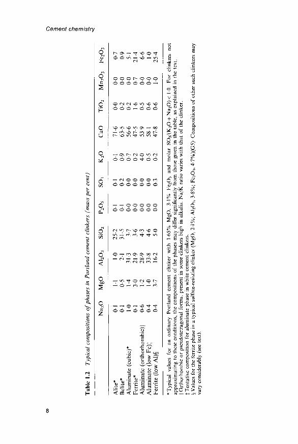
1.1 Introduction1.1.1 Portland cement: generalPortland cement is made by heating a mixture of limestone and clay, orother materials of similar bulk composition and sufficient reactivity,ultimately to a temperature of about 1450°C. Partial fusion occurs, andnodules of clinker are produced. The clinker is mixed with a few per centof calcium sulfate and finely ground, to make the cement. The calciumsulfate controls the rate of set and influences the rate of strengthdevelopment. It is commonly described as gypsum, but this may be partlyor wholly replaced by other forms of calcium sulfate. Some specificationsallow the addition of other materials at the grinding stage. The clinkertypically has a composition in the region of 67% CaO, 22% SiO2, 5%A12O3, 3% Fe2O3 and 3% other components, and normally contains fourmajor phases, called alite, belite, aluminate and ferrite. Several otherphases, such as alkali sulfates and calcium oxide, are normally present inminor amounts. Hardening results from reactions between the majorphases and water.
Alite is the most important constituent of all normal Portland cementclinkers, of which it constitutes 50-70%. It is tricalcium silicate (Ca3SiO5)modified in composition and crystal structure by ionic substitutions. Itreacts relatively quickly with water, and in normal Portland cements isthe most important of the constituent phases for strength development; atages up to 28 days, it is by far the most important.
Belite constitutes 15-30% of normal Portland cement clinkers. It isdicalcium silicate (Ca2SiO4) modified by ionic substitutions and normallypresent wholly or largely as the /? polymorph. It reacts slowly with water,thus contributing little to the strength during the first 28 days, butsubstantially to the further increase in strength that occurs at later ages.By one year, the strengths obtainable from pure alite and pure belite areabout the same under comparable conditions.
Aluminate constitutes 5-10% of most normal Portland cementclinkers. It is tricalcium aluminate (Ca3Al2O6), substantially modifiedin composition and sometimes also in structure by ionic substitutions.

Cement chemistry
It reacts rapidly with water, and can cause undesirably rapid settingunless a set-controlling agent, usually gypsum, is added.
Ferrite makes up 5-15% of normal Portland cement clinkers. It is tetra-calcium aluminoferrite (Ca2AlFeO5), substantially modified in composi-tion by variation in Al/Fe ratio and ionic substitutions. The rate at whichit reacts with water appears to be somewhat variable, perhaps due todifferences in composition or other characteristics, but in general is highinitially and low or very low at later ages.
1.1.2 Types of Portland cementThe great majority of Portland cements made throughout the world aredesigned for general constructional use. The standard specificationswith which such cements must comply are similar, but not identical, inall countries and various names are used to define the material, such asClass 42.5 Portland cement in current European and British standards(42.5 is the minimum 28-day compressive strength in MPa), Types I andII Portland cement in the ASTM (American Society for Testing andMaterials) specifications used in the USA, or Ordinary Portland Cement(OPC) in former British standards. Throughout this book, the term'ordinary' Portland cements is used to distinguish such general-purposecements from other types of Portland cement, which are made in smallerquantities for special purposes.
Standard specifications are, in general, based partly on chemicalcomposition or physical properties such as specific surface area, andpartly on performance tests, such as setting time or compressive strengthdeveloped under standard conditions. The content of MgO* is usuallylimited to 4-5%, because quantities of this component in excess of about2% can occur as periclase (magnesium oxide), which through slow reac-tion with water can cause destructive expansion of hardened concrete.Free lime (calcium oxide) can behave similarly. Excessive contents of SO3
can also cause expansion, and upper limits, typically 3-5% for ordinaryPortland cements, are usually imposed. Alkalis (K2O and Na2O) canundergo expansive reactions with certain aggregates, and some specifica-tions limit the content, e.g. to 0-6% equivalent Na2O (Na2O + 0-66 K2O).Other upper limits of composition widely used in specifications relate tomatter insoluble in dilute acid, and loss on ignition. Many other minorcomponents are limited in content by their effects on the manufacturingprocess, or the properties, or both, and in some cases the limits aredefined in specifications.
Rapid-hardening Portland cements have been produced in variousways, such as varying the composition to increase the alite content, finergrinding of the clinker, and improvements in the manufacturing process,
* Confusion can arise because the names or formulae of compounds can be used to denoteeither phases or components; this applies especially to CaO and MgO. Here and elsewhere,chemical or mineral names of oxides (e.g. calcium oxide, magnesium oxide, lime, periclase)will generally be used for phases, and formulae (e.g. CaO, MgO) for components. Mineralnames or prefixed formulae (e.g. a-A!2O3) are never used for components.

Portland cement and its major constituent phases
e.g. finer grinding or better mixing of the raw materials. The alitecontents of Portland cements have increased steadily over the one and ahalf centuries during which the latter have been produced, and manycements that would be considered ordinary today would have beendescribed as rapid hardening only a few decades ago. In the ASTMspecifications, rapid-hardening Portland cements are called high earlystrength or Type III cements. For both ordinary and rapid-hardeningcements, both lower and upper limits may be imposed on strengths at 28days, upper limits being a safeguard against poor durability resultingfrom the use of inadequate cement contents in concrete.
Destructive expansion from reaction with sulfates can occur not only ifthe latter are present in excessive proportion in the cement, but also fromattack on concrete by sulfate solutions. The reaction involves the A12O3-containing phases in the hardened cement, and in sulfate-resistingPortland cements its effects are reduced by decreasing the proportion ofthe aluminate phase, sometimes to zero. This is achieved by decreasingthe ratio of A12O3 to Fe2O3 in the raw materials. In the USA, sulfate-resisting Portland cements are called Type V cements.
White Portland cements are made by increasing the ratio of A12O3 toFe2O3, and thus represent the opposite extreme in composition to sulfate-resisting Portland cements. The normal, dark colour of Portland cementis due to the ferrite, formation of which in a white cement must thus beavoided. It is impracticable to employ raw materials that are completelyfree from Fe2O3 and other components, such as Mn2O3, that contributeto the colour. The effects of these components are therefore usuallyminimized by producing the clinker under slightly reducing conditionsand by rapid quenching. In addition to alite, belite and aluminate, someglass may be formed.
The reaction of Portland cement with water is exothermic, and whilethis can be an advantage under some conditions because it accelerateshardening, it is a disadvantage under others, such as in the construction oflarge dams or in the lining of oil wells, when a cement slurry has to bepumped over a large distance under pressure and sometimes at a hightemperature. Slower heat evolution can be achieved by coarser grinding,and decreased total heat evolution by lowering the contents of alite andaluminate. The ASTM specifications include definitions of a Type II or'moderate heat of hardening' cement, and a more extreme Type IV or 'lowheat' cement. The Type II cement is also suitable for conditions exposed tomoderate sulfate attack, and is widely used in general construction work.Heat evolution can also be decreased by partially replacing the cement byflyash (pulverized fuel ash; pfa) or other materials (Chapter 9), and this istoday a widely used solution. The specialized requirements of oil wellcements are discussed in Section 11.8.
7.7.3 Cement chemical nomenclature and other abbreviationsChemical formulae in cement chemistry are often expressed as sums ofoxides; thus tricalcium silicate, Ca3SiO5, can be written as 3CaO-SiO2.This does not imply that the constituent oxides have any separate

Cement chemistry
existence within the structure. It is usual to abbreviate the formulae of thecommoner oxides to single letters, such as C for CaO or S for SiO2,Ca3SiO5 thus becoming C3S. This system is often combined withorthodox chemical notation within a chemical equation, e.g.
3CaO + SiO2 -> C3S (1.1)
or even within a single formula, as in CnA7-CaF2 for Ca12Al14O32F2.The abbreviations most widely used are as follows.
C = CaO S = SiO2 A = A12O3 F = Fe2O3
M - M g O K = K2O S = S O 3 N = Na2O
T - T i O 2 P = P2O5 H = H2O C = C O 2
The formulae of the simple oxide phases (e.g. CaO) are usually written infull. Other abbreviations and units used in this book are as follows.
1.1.3.1 TechniquesBEI = backscattered electron imaging. BSE = backscattered electron.DTA = differential thermal analysis. EPMA = electron probe microana-lysis. ESCA = electron spectroscopy for chemical analysis (X-ray photo-electron spectroscopy). GLC = gas-liquid chromatography. GPC = gelpermeation chromatography. IR = infrared. MIP = mercury intrusionporosimetry. NMR = nuclear magnetic resonance. QXDA = quantitativeX-ray diffraction analysis. SEM = scanning electron microscop(e,y).STEM = scanning transmission electron microscop(e,y). TEM = trans-mission electron microscop(e,y). TG = thermogravimetry. TMS = tri-methylsilyl(ation). XRD = X-ray diffraction. XRF = X-ray fluorescence.
1.1.3.2 MaterialsC-S-H = poorly crystalline or amorphous calcium silicate hydrate ofunspecified composition. Ggbs = ground granulated blastfurnace slag.Hep = hardened cement paste. Pfa = pulverized fuel ash (flyash).
1.1.3.3 Properties or reactionsAR = alumina ratio (alumina modulus). ASR = alkali silica reaction.DEF = delayed ettringite formation. LSF = lime saturation factor.SR = silica ratio (silica modulus). Cx = analytical (total) concentrationof x, irrespective of species, [x] = concentration of species x. {x} = activityof species x. RH = relative humidity. Na2Oe = equivalent Na2O (mass %Na2O + 0-66 K2O). (+)2K, (-)2K, optic sign and optic axial angle.
1.1.3.4 Pressure unitsIMPa = I N mm"2 = 10 bar = 9.87 atm = 7500 torr - 145-0 lb in"2 =10-198 kg cm"2.
1.2 Alite1.2.1 Polymorphism and crystal structureOn being heated, pure C3S undergoes a series of reversible phasetransitions, which have been detected by a combination of DTA,

Portland cement and its major constituent phases
high-temperature XRD and high-temperature light microscopy (B1,G1,M1-M5,R1,R2,Y1):
620°C 920°C 980°C 990°C 1060°C 1070°CTi ^ T2 <=* T3 <=* Mi <=* M2 <=* M3 <=> R
(T = triclinic, M = monoclinic, R = rhombohedral)
The pure compound, when cooled to room temperature, is thus TV Inproduction clinkers, due to the incorporation of substituent ions, theform present at room temperature normally approximates to Mi or M3
or a mixture of these; rarely, T2 is found (M1-M5,T1). There has beensome uncertainty as to the number and nomenclature of these poly-morphs; reported M l b and M2b forms appear to be identical with M3,leaving reported M i a and M2a forms to be called simply M\ and M2
respectively (M4,M5).Jeffery (Jl) made the first determination of the crystal structure. He
showed that the forms now known as R, Ti and M3 had closely similarstructures, and determined the approximate or pseudostructure commonto all three; it was built from Ca2+, SiO^" and O2~ ions, the last beingbonded only to six Ca2+ ions, as in CaO. Later, more exact determinationswere reported for Tj (G2), M3 stabilized by Mg2+ (Nl), M3 with increaseddisorder isolated from a works clinker (M6), R at 1200°C (N2) andR stabilized with Sr2+ (II). Figure 1.1 shows the structure of the Rform. The known structures are all closely similar as regards the posi-tions of the Ca2+ and O2~ ions and of the Si atoms, but differ markedly inthe orientations of the SiO^" tetrahedra, which show varying degreesof disorder.
The structural differences between the polymorphs affect the coordina-tion of the Ca2+ ions and the O atoms of the SiO*" tetrahedra. For eachpolymorph, there are several crystallographically distinct Ca sites, havingdifferent coordination, and for a given site, the coordination sometimesvaries between individual atoms due to orientational disorder in thesurrounding SiO4 tetrahedra. Definitions of the Ca coordination numbersare somewhat arbitrary due to variations in the lengths of the bonds; e.g.in the R form at 1200°C, the Ca atoms in one of the sites could beregarded as 7 coordinated if bonds as long as 0-296 nm are counted, and5 coordinated if they are not (N2). If such abnormally long bonds areexcluded, the mean coordination number of the Ca is 5-66 in the Rpolymorph, 6-15 in M3 and 6-21 in Ti (M5). In relation to reactivitytowards water, the coordination of the oxygen atoms is possibly moreimportant than that of Ca. This has not been discussed in detail in theliterature, but mean oxygen coordination numbers may be expected toincrease with those of calcium.
Table 1.1 gives the crystal data for the C3S polymorphs that have beenobtained using single-crystal methods. The literature contains additionalunit-cell data, based only on powder diffraction evidence. Some of thesemay be equivalent to ones in Table 1.1, since the unit cell of a monoclinicor triclinic crystal can be defined in different ways, but some are certainlyincorrect. Because only the stronger reflections are recorded, and for

Cement chemistry
xOoooic.' 213jSl
[01
Fig. 1.1 Crystal structure of the R-modification of C3S, based on the results ofNishi and Takeuchi (N2) and showing Ca atoms (large open circles), Si atoms(small open circles), oxide ions (large hatched circle) and oxygen tetrahedra(triangles). Heights of atoms are in thousandths of the cell height (c = 2-5586nm),slashes denoting statistical alternatives. Oxygen tetrahedra are shown in averagedorientations; in reality, each is tilted around its enclosed Si atom statistically in anyone of three directions so as to preserve the threefold symmetry. All tetrahedra pointupwards excepting those surrounding the Si atoms at height 213, of which 70% pointdownwards and 30% upwards. Only the bottom third of the cell is shown, the middleand top thirds being derivable from it by translations of 1/3, 2/3, 1/3 and 2/3, 1/3,2/3 parallel to the a, b and c axes respectively.
Table 1.1 Crystal data for the C3S polymorphs
Polymorph
Pseudo structureR (at 1200°C)R (stabilized
with Sr)M3 (stabilized
with Mg)M3 (ex clinker;
less ordered)Ti
Spacegroup
R3mR3mR3m
Cm
Cm
pi
000
3
1
1
i
a
•70•7135•70567
•3083
•2235
•167
Cell parameters
b
0-7027
0-7073
1-424
c
2-502-55862-4974
1-8499
0-9298
1-372
(«, b,
a
105-5
c in nm)
P
94-12°
116-31°
0 94-3°
7
120°120°120°
90-0°
Z
999
36
6
18
Ref.
JlN211
Nl
M6
G2

Portland cement and its major constituent phases
other reasons, it is doubtful whether the unit cells of these complexstructures can be reliably determined by powder methods. The unit cellsof the Ti, M3 and R forms are superficially somewhat different, butall are geometrically related; transformation matrices have been given
1.2.2 Tricalcium silicate solid solutionsHahn et al (H2) reported a detailed study of the limits of substitutionin C3S of MgO, A12O3 and Fe2O3, alone and in combination. Theyconcluded that Ca2+ could be partly replaced by Mg2+ and that bothCa2+ and Si4+ could be partly replaced by Al3+ or Fe3+. They found themaximum content of MgO to be 2-0% at 1550°C, falling to 1-5% at1420°C. The limits for A12O3 and Fe2O3 were 1.0% and 1-1% respect-ively, but Al3+ and Fe3+ competed for sites, and the limit for each waslowered if the other was present. A subsequent study using 27A1 NMRindicated that the Al was present almost entirely in tetrahedral sites, thusexcluding substitution of Al3+ for Ca2+ (SI). Woermann et al. (Wl)found a limit of 14% for either Na2O or K2O at 1500°C.
Hahn et al. (H2) found that incorporation of Mg2+, Al3+ or Fe3+ insufficient quantity caused the higher temperature polymorphs to persiston cooling to room temperature. For each combination of substituentsstudied, increase in the total proportion of substituents led to the persist-ence of successively higher temperature polymorphs in the sequenceTi ->T 2 ->M!. In the system CaO-MgO-Al2O3-SiO2, total contents ofsubstituent oxides of about 1% caused T! to be replaced by T2, and onesof about 2% caused T2 to be replaced by Mj. Slightly higher totalsubstituent contents were needed to effect each of these changes if Fe2O3
was present.
1.2.3 Compositions of alites in clinkersPure C3S contains 73.7% of CaO and 26.3% of SiO2. Alites in clinkerstypically contain 3-4% of substituent oxides. Boikova (B2) found apositive correlation between the total percentage of substituent oxides inthe alite (/a) and the percentage of MgO in the clinker (Mc). Her resultsare approximately fitted by the equation /a = 0-7Mc-h2-l.
Many workers have analysed alites from ordinary production clinkersby X-ray microanalysis (B3,B4,G3,G4,H3-H5,K1,M6,M7,S2,T2,T3,U1)or chemical analysis of separated material (U2,Y1). Alites in white (B4)and iron-rich (G5,H6) clinkers have been analysed. The most importantsubstituents are Mg2+, Al3+ and Fe3+, and there is wide agreement thatthe contents of MgO and probably also of Fe2O3 in the alite increase withthose in the clinker. Since MgO replaces CaO, the content of CaOdecreases with that of MgO in the clinker. Taking these relationshipsinto account, as well as some less important variations with clinkercomposition and the errors inherent in either experimental method, theagreement between the various sets of data is generally good.
In the following discussion, symbols of the type Oa and Oc are used todenote the contents of oxide component O in the alite and in the clinker,
Tab
le 1
.2
Typ
ical
com
posi
tion
s of
pha
ses
in P
ortl
and
cem
ent
clin
kers
(m
ass
per
cent
)
Ali
te*
Bel
ite*
Alu
min
ate
(cu
bic
)*F
erri
te*
Alu
min
ate
(ort
ho
rho
mb
ic)f
Alu
min
ate
(low
¥€
)\F
erri
te (
low
Al)
§
Na
2O
01
01
10
01
0-6
04
0-4
Mg
O
11
0-5
14
30
1-2
10
3-7
A1 2
O3
10
21
31-3
21-9
28-9
33-8
16-2
SiO
2
25-2
31-5 3-7
3-6
4-3
4-6
50
P2O
5
01
01
00
00
00
00
00
so3
01
0-2
00
00
00
00
0-3
K2O
01
09
0-7
0-2
40
0-5
0-2
CaO
71
663
-556
-647
-553
-958
-147
-8
TiO
2
00
0-2
0-2
1-6
0-5
0-6
0-6
Mn
2O
3
00
00
00
0-7
00
00
10
Fe 2
O3
0-7
0-9
51
21
46-
61
02
54
* T
ypic
al
valu
es
for
an o
rdin
ary
Por
tlan
d ce
men
t cl
inke
r w
ith
1-65
% M
gO
, 3
1%
Fe 2
O3
and
mol
ar
SO
3/(K
2O +
Na 2
O)<
10
. F
or
clin
kers
no
tap
prox
imat
ing
to t
hese
con
diti
ons,
th
e co
mpo
siti
ons
of t
he
phas
es m
ay d
iffer
sig
nifi
cant
ly f
rom
tho
se g
iven
in
the
tabl
e, a
s ex
plai
ned
in t
he
text
.f
Ort
horh
ombi
c o
r ps
eudo
tetr
agon
al f
orm
s, p
rese
nt i
n so
me
clin
kers
hig
h in
alk
alis
. N
a/K
rat
io v
arie
s w
ith
that
of
the
clin
ker.
I T
enta
tive
com
posi
tion
for
alu
min
ate
phas
e in
whi
te c
emen
t cl
inke
rs.
§ V
alue
s fo
r th
e fe
rrite
pha
se i
n a
typi
cal
sulf
ate-
resi
stin
g cl
inke
r (M
gO,
2-1%
; A
I2O
3, 3
-8%
; Fe
2O3,
4-7
%)(
G5)
- C
ompo
siti
ons
of o
ther
suc
h cl
inke
rs m
ayva
ry c
onsi
dera
bly
(see
text
).
o CD CD 13 3 CD

Portland cement and its major constituent phases
respectively. For MgO, Kristmann's (Kl) data indicate the approximaterelations Ma = 0-67xMc for M c <30 and Afa«2-0 for M c >30.Yamaguchi and Takagi (Yl), Terrier (T2) and Maki et al. (Ml) foundsimilar correlations, but with slopes of 0-74, 045 and 0-58 respectively.For a series of clinkers of low Al/Fe ratio, Hall and Scrivener (H6) foundMa = 0-64 x Mc - 0-23. For Fe2O3, Kristmann's data (Kl) indicate theapproximate relation Fa = 0-33 x Fc for Fc<4%. There does not appearto be a significant correlation between A,d and Ac. Boikova (B2) reportedratios of 0-34-0-82 for MJMC, 0-09-0-23 for AJAC and 0-17-0-36 forFJFC. The SO3 contents of clinker alites are often very low, but values upto 0.9% have been reported for clinkers low in MgO and alkalis (G6) orhigh in SO3 (M8).
Taken as a whole, the evidence indicates that the significantsubstitutions in clinker alites are of Na+, K+, Mg2+ and Fe3+ for Ca2+
and of Al3+, P5+ and S6+ for Si4+. Observed contents of K2O and Na2Oare much below the limits found by Woermann et al. (Wl). Table 1.2includes a typical composition for a clinker with 1-65% MgO and 3-1%Fe2O3, and Table 1.3 includes atomic ratios calculated from it.
1.2.4 Polymorphic modifications of the alites in clinkersMaki and co-workers (M2-M5,M9) studied the crystallization of alite byhigh-temperature light microscopy of thin sections together with thermaland X-ray methods. It crystallizes from the clinker liquid at about 1450°Cas the R polymorph, which inverts to lower temperature forms oncooling. Due to the lowering of symmetry, each crystal usually containsseveral optically distinct domains, recognizable in thin section usingpolarized light. At the higher temperatures of formation or recrystalliza-tion within the normal range, small crystals, relatively high in substituentions, are formed, which on cooling invert to M3. Crystals formed at lowertemperatures are larger and poorer in substituent ions, and may undergofurther transition, partial or complete, to Mi or, rarely, to T2.
The MgO and SO3 contents of the clinker are especially important indetermining whether the transformation into Mi occurs (Fig. 1.2; M7,M9-M11). High ratios of MgO to SO3 promote nucleation rather thangrowth, resulting in formation of small, euhedral crystals of M3. Incontrast, low ratios favour rapid, unstable growth, giving rise to large,irregularly shaped crystals, often of M^ These can be skeletal ordendritic, with relatively high contents of substituents and inclusionsboth of clinker liquid and of minute crystals of belite and free lime. Highratios of alkalis to SO3 lessen the tendency to form Mi, as the SO3 is thenlargely combined as alkali sulfates. Crystals containing both M3 and Mxcan occur, and are often zoned, with cores of Mi and peripheral regionsof M3. This is because the clinker liquid becomes richer in MgO ascrystallization proceeds, causing the material deposited later to persistas M3. The M3 to Mi transformation is also affected by the cooling rate,slow cooling favouring the transformation to M]. In certain slowlycooled clinkers, further transformation may occur, giving T2. This islikely to occur only if the alite is particularly low in substituents.

Tab
le 1
.3
Ato
mic
rat
ios
for
phas
es(s
ee fo
otno
tes
to T
able
1.2
)
Alit
e
Bel
ite
Alu
min
ate
(cub
ic)
Fer
rite
Alu
min
ate
(ort
horh
ombi
c)
Alu
min
ate
(low
Fe)
Fer
rite
(lo
w A
l)
K <1 3 4 1
23 3 1
in P
ortl
and
cem
ent
Na 1 1 9 1 5 3 3
Ca
291
194
200
273
296
198
200
265
303
276
291
197
-20
0
clin
kers
,
Mg 6 2 9 17 8 7 22
calc
ulat
ed f
rom
Mn
300 2 3
Ti 1 5 2 2 2
the
typi
cal
Fe 2 2 17 62 200 23 3 75
com
posi
tions
in
Tab
le 1
.2
Al 4
100 7
100
166
200
100
157
200
176
-200 75
-200
Si
P
96
<1
90 17 14 20 20 20
S <1 1
O 500
393
600
500
600
600
500
Cement cherrlistry
Portland cement and its major constituent phases
? 3 0
~, 20
oenz 10
0
0
00
o
o o
0 °O ° °s\
8 o *' 'O • $9
M3
*': • .
0 10 20SO3 in Clinker (%)
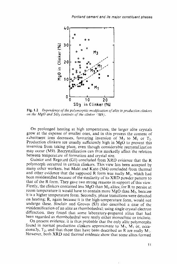
Fig. 1.2 Dependence of the polymorphic modification ofalite in production clinkerson the MgO and SO3 contents of the clinker (M9).
On prolonged heating at high temperatures, the larger alite crystalsgrow at the expense of smaller ones, and in this process the content ofsubstituent ions decreases, favouring inversion of M3 to Mj or T2.Production clinkers are usually sufficiently high in MgO to prevent thisinversion from taking place, even though considerable recrystallizationmay occur (M9). Recrystallization can thus markedly affect the relationbetween temperature of formation and crystal size.
Guinier and Regourd (Gl) concluded from XRD evidence that the Rpolymorph occurred in certain clinkers. This view has been accepted bymany other workers, but Maki and Kato (M4) concluded from thermaland other evidence that the supposed R form was really M1? which hadbeen misidentifled because of the similarity of its XRD powder pattern tothat of the R form. They gave two strong reasons in support of this view.Firstly, the clinkers contained less MgO than M3 alites; for R to persist atroom temperature it would have to contain more MgO than M3, becauseit is a higher temperature form. Secondly, phase transitions were detectedon heating; R, again because it is the high-temperature form, would notundergo these. Sinclair and Groves (S3) also described a case of themisidentification of an alite as rhombohedral; using single crystal electrondiffraction, they found that some laboratory-prepared alites that hadbeen regarded as rhombohedral were really either monoclinic or triclinic.
On present evidence, it is thus probable that the only alite polymorphsfound in normal production clinkers approximate to M3, Mi or, occa-sionally, T2, and that those that have been described as R are really Mi.However, both XRD and thermal evidence show that some alites formed
11

Cement chemistry
in the presence of fluoride are rhombohedral (Ml2). XRD and opticalevidence indicates that the commonest polymorph in production clinkersis almost certainly M3 or a less ordered form of it. The presence of M3 ina works clinker has also been demonstrated using single crystal electrondiffraction (HI).
1.2.5 X-ray powder patterns and densities of tricalcium silicateand alites
A number of experimentally determined XRD powder patterns have beenreported for C3S and alite polymorphs (PI), but because of uncertaintiesin the indexing and sometimes in identification of the polymorph, theseare usefully supplemented by patterns calculated from the crystalstructures (Appendix; M6). The patterns of the polymorphs are closelyalike, and interpretation is complicated in clinkers by the fact that manypeaks overlap ones of other phases. The pattern depends not only on thepolymorph or mixture of polymorphs present, but also on the nature andamounts of the substituent ions present in each. It is therefore not always
D
32° 33° 32° 33° 32° 33°DEGREES 26 (Cu Ka)
32° 33°
52° 51° 52° 51° 52°DEGREES 29 (Cu Ka)
Fig. 1.3 Portions of XRD powder patterns of (A) the T, modification of C3S at605°C (after R2); (B), (C) and (D) clinkers containing, respectively, M3,(M3 + Mj) and M, alites (after M4). Indexing of T, and M3 patterns is based onthe axes in Table 1.1 and calculated intensities.
12

Portland cement and its major constituent phases
easy or even practicable to identify the polymorph or polymorphs in aclinker by the XRD powder pattern alone. The patterns differ principallyin the fine structures of certain peaks (B2,G1,J1,M4,M5,R1). Figure 1.3shows characteristic portions of the patterns of Ti C3S and of someclinkers. Mi alite, as present in clinkers, probably always has the maxi-mum MgO content possible for this polymorph, and as such has a unitcell or pseudocell that is geometrically almost hexagonal. This causes thepeak at about 51-7° 26 (Cu Ka radiation) to be almost a singlet; thecorresponding peak of the M3 alite is a well-defined doublet, and those ofTi C3S and T2 alite are triplets. There are also differences in the peaks at32-33° 26, but these are less useful because of overlaps with other phases.Because of their high relative intensities, care is needed with these latterpeaks to avoid intensity errors from extinction.
The X-ray density of Ti C3S is 3120 kgrn"3 (G2); that of M3 alite, cal-culated assuming the atomic parameters of Nishi et al. (Nl) and thecomposition (Cao.98Mgo.oi Al0.oo67Feooo33)3(Sio-97Al0.o3)05, is 3150 kg m"3.
1.2.6 Optical, thermal and other dataT{ C3S is biaxial with ( - )2K= 20-60°, and aAc h e x -0 -15° (Ol); therefractive indices are a = 1-7139, 7 = 1-7172 for pure C3S and a = 1-7158—1-7197, 7 = 1-7220-1-7238 for typical clinker alites, all determined usingsodium light (B5). In thin sections in polarized light, Mi and M3 are mostreadily distinguished by the maximum birefringence, which is 0-005 to0-006 for M3 and 0-003 for Mi (M2-M5). Other differences in opticalproperties include the optic orientation referred to the hexagonal axesof the R form, whose shape persists through the transitions that occur oncooling, and the optic axial angle; Maki and Kato (M4) give details.
It is doubtful whether the polymorphs can be reliably distinguished byDTA, since both the Mi and the M3 forms are metastable at lowtemperatures and transform to T2 at about 700°C (M4,M5). This effect isnormally swamped by the endothermic f3 to a'L transition of the belite.Due to the effect of substituents, neither T3 nor M2 appears to form onheating. With alites relatively low in substituents, endotherms occur at790-850°C, giving Mi and at 950°C, giving M3. Clinkers high in MgO,in which the alite is present entirely as M3, normally show no thermaleffects attributable to the alite until more than 1000°C, when transitionto R occurs.
A substituted C3S has been found in nature and given the mineralname 'hatrurite' (G7). The rock containing it is interesting because itcontains other phases present in clinker and appears to have been formedunder conditions somewhat similar to those existing in a cement kiln.
1.3 Belite1.3.1 Polymorphism and crystal structureThermal and X-ray evidence (B6,N3,R1) shows that five polymorphs ofC2S exist at ordinary pressures, viz.
13

Cement chemistry
1425°C 1160°C 630-680°C <500°C
690°C
780-860°C
(H = high; L = low). The structures of all are built from Ca2+ and ^ions. The arrangements of these ions are closely similar in the a, a'H, a'Land (3 polymorphs, but that in 7-C2S is somewhat different. As with C3S,the higher temperature polymorphs cannot normally be preserved oncooling to room temperature unless stabilized by substituent ions. 7-C2Sis much less dense than the other polymorphs, and this causes crystals orsintered masses of /3-C25 to crack and fall to a more voluminous powderon cooling, a phenomenon known as dusting. If the crystallites of /3-C2Sare sufficiently small, the transformation does not occur, even if nostabilizer is present (Y2). In all normal Portland cement clinkers, thebelite contains enough stabilizing ions to prevent the transformation to7~C2S from taking place.
Many of the earlier crystal data reported for the C2S polymorphs werebased on powder XRD patterns obtained either at high temperatures orfrom stabilized preparations at room temperature. As with the C3S poly-morphs, such data are not always reliable. Table 1.4 gives data derivedfrom single-crystal evidence, which do not suffer from this limitation.
The structures of the a, a'H, a'L and (3 polymorphs (Figs 1.4A-C) allbelong to a large family typified by that of glaserite, K3Na(SO4)2 (M14).
Table 1.4 Crystal data for the dicalcium silicate polymorphs
Polymorph
a*
aFit
aL$
0%7
Cell parameters (lengths in
a
0-5579
0-949(y/3 x 0-548)
2-0871(3 x 0-6957)
0-55020-5081
b
0-559
0-9496
0-67451-1224
c
0-7150
0-685
0-5600
0-9297 /:0-6778
nm)
Anglei
7 = 120°
?= 94-59°
Spacegroup
P63/mmc(?)Pcmn
Pna2!
P2i/nPbnm
Axialrelation ||
—ac
abc
bca
cabbac
Z
2
4
12
44
Ref.
U3
S4
12,13
J2U4
* Stabilized with Ba. Other space groups (P3ml, P63mc) have been proposed (Ml3). Thespace group P63/mmc arises either from a domain structure (U5,U6) or from disorder inthe orientations of the SiC>4 tetrahedra (Ml3).t Stabilized with P2O5 and examined at 1200°C.t Stabilized with Sr. A different superstucture can also form (K2,R3), in which the a, b and caxes of the a'H form are respectively doubled, doubled and unchanged.§ Crystal prepared from a CaCl2 melt without additional stabilizer. Crystals showing asuperstructure have been observed (K2).fWherenot90°.|| Sequence of axes respectively equivalent to a, b and c of the a'H polymorph.
14

Portland cement and its major constituent phases
= 0-558nm- -b = 0-559nm—-i
Ec
A. <x-C2S
" O 28 28U9Q 78 78
B.
-a = 0- 508 nm—|
D. y-c2s
Fig. 1.4 Crystal structures of C2S polymorphs (after U7,U8). Large, open circlesrepresent calcium atoms, small closed circles silicon atoms, and triangles tetrahedraof oxygen atoms. Heights of atoms are given as hundredths of the cell height (0-68-0-7lnm). For a-C2S, the structure shown is that of an individual domain of spacegroup Pile. The structures are shown in the relative orientations found when theyare inter converted, an unconventional choice of origin being adopted for j-C2S toclarify the relation to the other polymorphs.
15

Cement chemistry
As is apparent from the data in Table 1.4, the unit cells of all fourare closely related. Structure determinations have been reported forthe a (M13,U5,U7), c/H (M13), a'L (I2,I3,U9) and /? (D1,J2,M13,M15)polymorphs. The space group of the a form may vary according to thetemperature and the nature of the stabiliser, if any (K2). a'L is in practicea generic term for complex variants of a^, as two different superlatticeshave been found to occur (K2,R3).
The structures of the a'H, a'L and (3 polymorphs are derived from thatof a-C2S by progressive decreases in symmetry, which arise from changesin the orientations of the SiO^" tetrahedra and small movements of Ca2+
ions. The quantities of substituent ions needed to stabilize the highertemperature polymorphs at room temperature decrease along thesequence from a- to /3-C2S. The situation parallels that existing withthe C3S polymorphs, described in Section 1.2.2. Also as in the latter case,and for the same reason, these C2S polymorphs differ in calcium ioncoordination. In /?-C2S, some of the Ca2+ ions have 7, and others 8oxygen atoms within 0-288 nm (J2). A modulated structure, i.e. one inwhich compositional or structural variations occur with a statisticalperiodicity that is not a rational multiple of that of the basic structure,has been observed in a polymorph of C2S (Fl).
The crystal structure of 7-C2S is similar to that of olivine,(Mg,Fe)2SiO4 (Fig. 1.4D; M13,U4). The calcium is octahedrally coor-dinated. The unit cell and the arrangement of Ca2+ and SiO^" ions showsome similarities to those of the other polymorphs, but also importantdifferences. It has often been supposed that transformations involvingthis form entail total reorganization of the structure, but single crystalhigh-temperature XRD evidence indicates that this is not correct; theproducts are formed topotactically (i.e. in a definite crystallographicorientation relative to the starting material; Fig. 1.4), but fragmentbecause of the large volume change (B7,G8,K2,U8). 7-C2S scarcely reactswith water at ordinary temperatures.
1.3.2 Polymorphic forms and textures in clinker belitesXRD powder evidence shows that in the majority of clinkers the beliteis predominantly or entirely of/3-C2S structure (G1,Y1), though somepeaks are broadened (Gl) and the presence also of both a and a'(presumably a'h) forms has been reported (G1,O1,R1,Y1). Characteriza-tion of the polymorphic form is rendered difficult by the similaritiesbetween their powder patterns (Fig. 1.5) and by overlaps between thepeaks and ones of other phases, especially alite, but has been aided byexamination of fractions in which the belite has been concentrated bychemical (Rl) or heavy liquid (Yl) separation.
The belite grains in Portland cement clinkers frequently show complex,striated structures. These have been studied over a long period by workersusing light microscopy; Yamaguchi and Takagi (Yl) and Ono et al. (Ol),who also used XRD and other methods, gave the first substantiallycomplete interpretations. Groves (G9) and Fukuda and Maki (F2,F3)
16

Portland cement and its major constituent phases
mo B
30° 35° 30°DEGREES 26
35° 30°(Cu Kai)
35°
Fig. 1.5 Portions of XRD powder patterns (microdensitometer traces of Guinierphotographs) of (A) a-C2S at 1500°C, (B) a'L-C2S at 1000°C and (C) (3-C2S.Indices are based on axes used in Table 1.4 (after Rl).
extended these results, using single-crystal electron diffraction and othermethods. Kim et al. (K2) have discussed transformation mechanisms.
A very common type of belite grain in production clinkers, called Type Ibelite, is rounded, typically 20 to 40 fim in mean dimension, and showsseveral sets of parallel striations. Such crystals have formed as the apolymorph and the striations arise from the lowering of symmetryinherent in the a to a'H and af
L to (3 transformations that occur on cool-ing. Type I belite crystals consist largely or wholly of the ft polymorph,though some a may remain. Other phases tend to be exsolved betweenthe lamellae, since the lower-temperature polymorphs are less able toaccommodate substituent ions.
Type II belite grains are typically irregular in shape and show only oneset of striations. They are rare in modern clinkers. The striations arisefrom the a'L to (3 transformation. The restricted number of orientationscan arise either because the crystals had formed below the a to a'Htransition temperature or because one of the twin components of the a'modification grew at the expense of the others (01). Belite can form inclinkers by additional mechanisms, sometimes at lower temperaturesthan those discussed above, and may not then show any striations.
Chan et al. (Cl) showed that material exsolved between lamellae or atgrain boundaries in synthetic belites was often compositionally farremoved from C2S, and structurally either amorphous or composed ofcrystalline phases of entirely different structure, such as C2AS, C3A orC3S2. They concluded that the possibilities of compositional variation in/3-C2S were considerably narrower than had often been supposed, thegrosser deviations from ideal composition being attributable to sucheffects. Evidence from 27A1 NMR is consistent with these results (SI).Chan et al. also concluded that, contrary to some earlier views, /3-C2Scannot be stabilized by excess CaO alone, and that the role of ionicsubstitution in stabilizing forms other than 7 to room temperature
17
Cement chemistry
needed to be reassessed, mechanical constraints associated with exsolu-tion providing a possible alternative explanation.
1.3.3 Compositions of belites in clinkersTable 1.2 includes an average composition for belites in ordinary produc-tion clinkers, based on the results of many studies by X-ray microanalysis(B3,G3,G4,H3,H4,K1,S2,T2) or chemical analysis of separated material(D1,Y1). As with alite (Section 1.2.3), most of the results from differentlaboratories are in relatively close agreement. Belites in white (B4) andiron-rich (G5,H6) clinkers have also been analysed. Pure C2S, forcomparison, contains 34-9% of SiO2 and 65-1% of CaO.
Clinker belites typically contain 4-6% of substituent oxides, ofwhich the chief are usually A12O3 and Fe2O3. The Al3+ is in tetrahedralsites (SI). With clinkers high in SO3, the belite tends to be high in thatcomponent; coupled substitution of 2A13++ S6+ for 3Si4+ probablyoccurs (B8). The SO3 content of the belite (Sb) is reported to be relatedto that ofthe clinker (Sc) by the relation Sb = 1.23SC + 0-24, or, alter-natively, Sb =3.36SC' +0-55, where Sc> excludes SO3 present in solublesulfate phases (H6). Correlations have been reported to exist between theMgO contents of the belite and the clinker (Kl), and the Al2O3/Fe2O3
ratios of the belite and the clinker (F4,H6), but there is disagreement inthe case of Fe2O3 (H6,K1). Early reports mention a compound KC23S12,but the K2O content of 3-5% corresponding to this formula is well abovethose found in clinker belites, and recent electron optical work indicatesthat the limit of K2O substitution is about 1-2% (Cl).
Any interpretation of belite analyses is at present tentative because ofthe uncertainties arising from exsolution effects. From the practicalstandpoint, it may be necessary to regard the exsolved material as form-ing part of the belite. Clinker belite compositions seem often to indicateratios of other atoms to oxygen above the theoretical value of 0-75. AsRegourd et al. (R3) noted, the C2S structures are too densely packed forthe presence of interstitial ions to appear likely, and it is possible thatvacancies occur in the oxygen sites. Table 1.3 includes atomic ratios, witha possible allocation of atoms to sites, corresponding to the compositiongiven in Table 1.2.
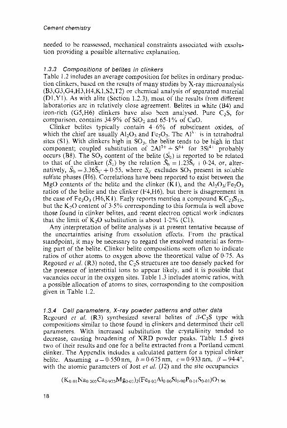
1.3.4 Cell parameters, X-ray powder patterns and other dataRegourd et al. (R3) synthesized several belites of /3-C2S type withcompositions similar to those found in clinkers and determined their cellparameters. With increased substitution the crystallinity tended todecrease, causing broadening of XRD powder peaks. Table 1.5 givestwo of their results and one for a belite extracted from a Portland cementclinker. The Appendix includes a calculated pattern for a typical clinkerbelite. Assuming a = 0-550 nm, b = 0-675 nm, c = 0-933 nm, ^=94-4°,with the atomic parameters of Jost et al. (J2) and the site occupancies
18

Portland cement and Its major constituent phases
Table 1.5 Cell parameters of belites
Composition
Ca2Feo.035Alo.035Sio.93O3.965*Ca2Feo.050Aloo50Sio-90O3.950*
a
0-0-0-
(nm)
550255025504
b
000
(nm)
•6750•6753•6762
c
000
(nm)
•9316•9344•9328
P
94-45°94-19°94-17°
* Laboratory preparation (R3).f Isolated from a clinker; also, Na, Ti, Mn, P, each< 001 (Dl).
the X-ray density is 3300 kg m 3. That for pure /?-C2S, based on Jostet a/.'s data, is 3326kgm~3, and that for pure 7-C2S, based on data ofUdagawa et al. (U4), is 2960 kg m"3.
Synthetic /3-C2S is biaxial positive with high 2V and a =1-717,7 = 1-735; 7-C2S is biaxial negative with 2F=60°, a = 1-642, /?= 1-645,7 = 1-654 (R4). In the Type I belites of clinkers, lamellae of /3 structurehave mean refractive index 1 -720 and birefringence 0015-0018, while forthe intervening material the corresponding values are 1-700-1 -710 and0-000-0-003 (Ol). Ono et al. (Ol) and Yamaguchi and Takagi (Yl) givefurther data on the optical properties of clinker belites.
Guinier and Regourd (Gl) summarized the thermal behaviour of C2Spolymorphs. On heating, /3-C2S shows endotherms beginning at 693°Cand 1450°C, due respectively to the (5 —> a'L and a'H —• a transitions; with7-C2S, the 693°C endotherm is replaced by a broad one beginning atabout 748°C due to the transition to a'L. The curve obtained on coolinga-C2S from 1500°C shows exotherms beginning at about 1456°C, 682°Cand 530°C, due respectively to the a->a'H, af
L —> j3 and (3 -> 7 transitions.The a'H —> a'L transition gives only a very weak effect at 1160°C.
/3-C2S, modified by solid solution, occurs in nature as larnite. Earlyidentifications of a'-C2S with bredigite were incorrect (B9,M16). a-C2Shas been assumed to resemble nagelschmidtite (Ca7Si2P2O16), but the unitcell of the latter seems to be more complex (Gl).
1.4 Aluminate1.4.1 Crystal structure: cubic, orthorhombic and
monoclinic modificationsPure C3A does not exhibit polymorphism. It is cubic, with a = 1-5263 nm,space group Pa3 and Z = 24; the structure is built from Ca2+ ions andrings of six A1O4 tetrahedra, of formula Al6O}jj~ (Ml7). These rings arehighly puckered, such that the Al atoms lie near to six of the corners of acube (Fig. 1.6). The unit cell is composed of 64 (43) subcells, of edgelength 0-3816 nm. Of these subcells, 8 are occupied by A16O18 rings; theCa2+ ions occur at the body centres of some of the remaining subcells andnear the corners of others. The coordination of those near the corners isoctahedral, while that of those at the body centres is irregular, with either5 or 6 oxygen atoms within 0-28 nm.
19

Cement chemistry
Fig. 1.6 A16O18 ring in the structure of C3A, showing the situations of thealuminium atoms near to the corners of a cube; based on the results of Mondal andJeffery (M17).
C3A can incorporate Na+ by substitution of Ca2+ with inclusion of asecond Na+ ion in an otherwise vacant site, thus giving solid solutions ofgeneral formula Na2xCa3_xAl206 (F5,R1,R5,T4). The substitutionoccurs without change in structure up to a limit of about 1% Na2O(x « 0-04). Higher degrees of substitution lead to a series of variants of thestructure (Table 1.6). In the absence of other substituents, the upper limitof Na2O substitution is 5.7%.
The Q structure (Table 1.6) is the C3A structure, with up to about 1%of Na2O present as described above. The Cn structure is a minor variantof it, of lower symmetry (T4); comparison of calculated XRD patterns
Table 1.6 Modifications of the C3A structure, of general formulaNa2xCa3.xAl2O6 (T4)
ApproximateNa2O (%)
0-1-01-0-2-42-4-3-73-7-4-64-6-5-7
Compositionalrange (x)
0-0-04004-010010-0160-16-0-200-20-0-25
Designation
c,C11C11 + O0M
Crystalsystem
CubicCubic-OrthorhombicMonoclinic
Spacegroup
Pa3P2,3
PbcaP2i/a
20

Portland cement and its major constituent phases
(T5) shows that there is little possibility of distinguishing the two bypowder XRD, unless by very precise determinations of the cell para-meter, Cn with 24% Na2O having a = 1-5248 nm (T4). In Cn, and byanalogy also in Q, the additional Na+ ions are located at the centresof the Al6Oi8 rings. The O structure (originally called Oi) resemblesQ and Cn in having a unit cell that is composed of pseudocubic sub-cells with edge lengths of approximately 0-38 nm, which contain Ca2+
ions and Al6Oi8 rings, but the arrangement of the rings within thetrue unit cell is entirely different (N4,T4). A preparation of compositionNao.875Ca8.375Al5.i75Feo.45oSio.3750i8 (3-3% Na2O) had a = 1-0879nm,b= 1-0845nm, c=l-5106nm, Z = 4 (T4). The M structure, which wasoriginally considered to be orthorhombic and called On (R5), is a slightlydistorted variant of the O structure; a preparation of compositionNai.5oCa8.25Al6Oi8 (5-7% Na2O) had a= 1-0877nm, 6=l-0854nm,c= 1-5135nm, /3 = 9O-l°, Z = A (T4).
Substantial proportions of the Al in these structures can be replaced byother ions, of which Fe3+ and Si4+ are the most important. Lee et al. (LI)found the limits of substitution under equilibrium conditions to bearound 2% for SiO2 and 3-4% for Fe2O3, but higher degrees ofsubstitution were obtainable under non-equilibrium conditions, such ascrystallization from undercooled melts. If Si4+ is present, fewer largecations are needed to maintain charge balance; this extends the solidsolution range of the O structure to lower Na2O contents and that of theM structure to higher ones (T4). The literature contains many referencesto an supposed compound NC8A3. This formula corresponds to an Na2Ocontent of 7-6%, which cannot be attained in C3A substituted only withNa+, and it is reasonably certain that this compound does not exist(F5,M18,R5,T4); however, if Si is also present, the upper limit of Nasubstitution is near to this value (M18,T4).
Pollitt and Brown (P2) were unable to prepare an analogue of theorthorhombic phase with K+ as the sole substituent, but obtained evidencethat K+ could stabilize it in clinker, probably because other substituentswere also present. Maki (Ml8) also failed to prepare K forms of theorthorhombic or monoclinic phases under equilibrium conditions, but bymoderately rapid cooling of melts he obtained orthorhombic crystalshaving cell parameters close to those of the corresponding sodium-containing phase. He considered that the presence of Si in the clinker liquidwould favour supercooling and thereby also non-equilibrium formationof the orthorhombic or monoclinic phase.
1.4.2 Other modificationsTwo further modifications of the C3A structure have been described. Onewas obtained as a high-temperature polymorph of the O and M formsand was considered on the basis of powder XRD evidence to betetragonal (R1,R5). It appeared to be metastable at room temperaturebut could be preserved by quenching. Later studies, using thermalanalysis, high-temperature light microscopy and high-temperature singlecrystal XRD (M19,M20,T4) showed, however, that the O modification
21

Cement chemistry
was structurally unchanged up to its decomposition temperature and thatthe M modification was reversibly transformed on heating into the Oform. A study of quenched material using powder XRD and singlecrystal electron diffraction (L2) confirmed that the supposed tetragonalform was really orthorhombic, though with a equal to b and thusgeometrically tetragonal. The space group was considered to be probablyPcaa, which differs from that (Pbca) of the normal O form; however,three of the indices assigned to the XRD powder peaks (023, 045 and 047)are incompatible with this space group, though not with Pbca. The high-temperature material may thus have the normal O structure and acomposition such that the a and b axial lengths are equal to withinexperimental error. Its persistence to room temperature appears to befavoured by relatively high contents of Na2O and Fe2O3 (LI).
The other C3A modification is a disordered, poorly crystalline form,called 4proto-C3A', which was obtained metastably from simulatedclinker liquids, either by rapid cooling or by static crystallization at lowtemperatures (BIO). It gave an XRD powder pattern with broadenedpeaks, corresponding to the systematically strong reflections of cubic C3Aindexable on the subcell with a w 0-39 nm. Analytical electron microscopyof individual crystals showed it to be very high in substituents, onepreparation, for example, having an Fe/Al ratio of 0-54 (H7).
1.4.3 Structural modifications of clinker aluminatesProduction clinkers have been found to contain cubic or orthorhombicforms of aluminate, alone or in combination. The monoclinic modifica-tion has not been observed. The orthorhombic modification is alsoknown as the prismatic, dark interstitial material, and is sometimespseudotetragonal. It can arise only if sufficient alkali is available, but itsformation appears to be favoured also by rapid cooling and by bulkcompositions potentially able to yield a relatively high proportion ofaluminate (Ml8).
Cubic aluminate in clinker is often finely grained and closely admixedwith dendritic crystals of ferrite; when it forms larger crystals, these tendto be equidimensional. The XRD powder pattern is characterized bystrong, singlet peaks at approximately 33-3°, 47-7° and 59-4° 26 (CuKaradiation; Fig. 1.7A), whose indices are, respectively, 044, 008 and 448.Patterns obtained either from clinker or from material in which thealuminate and ferrite phases have been concentrated by chemicalextraction of the silicates give a= 1-5223-1-5255 nm (Rl). The slightdecrease relative to the value of l-5263nm for pure C3A agrees withresults for synthetic sodium-substituted preparations (R1,T4). These dataare probably equally compatible with the presence of proto-C3A, but thecontents of substituents (Section 1.4.4) are considerably lower than thosefound in the latter material. There is probably not enough evidence toshow whether the modification is Q (Pa3) or Qi (P2i3).
The orthorhombic phase is recognizable in the light microscope orSEM by its occurrence as characteristic, lath-shaped crystals, which areoften twinned (Ml8). An XRD powder pattern of material from which
22

Portland cement and its major constituent phases
33 33° 34°
DEGREES 29 (Cu Kai)
33° 34°
Fig. 1.7 Portions of XRD powder patterns of clinkers containing (A) cubic, (B)orthorhombic and (C) pseudotetragonal modifications of the aluminate phase.Peaks marked A and F are due to aluminate andferrite phases respectively, and arereindexed, where necessary, to correspond to axes used in text and Table 1.7, and tocalculated intensities (after Rl).
the silicate phases had been removed showed a splitting of the strongpeak at 33-3° 26 into a strong singlet at approximately 33.2° and aweaker, close doublet at 32-9-33-0° (Fig. 1.7B). The unit cell parameterswere a = 1-0874nm, 6 = 1-0860 nm, c= 1-5120 nm (Rl). Another clinker,in which the aluminate was pseudotetragonal, gave a strong singlet peakat 33-2° and a weaker singlet at 33-0° (Fig. 1.7C), and the cell parameterswere a = b= 1-0867nm, c— 1-5123nm.
1.4.4 Compositions of clinker aluminatesBecause of the close admixture with other phases, which is often on ascale of 10 /im or less, X-ray microanalysis of the aluminate in clinkers isfrequently difficult or unreliable. Data have been reported for cubic,orthorhombic, pseudotetragonal or unspecified forms of the aluminate inordinary clinkers (B3,H3,K1,R1), for aluminate in high-iron clinkers(H6) and for aluminate (B4,G3,G4,S2) and glass (B4) in white cementclinkers. A study of laboratory clinkers indicated that slow coolingdecreased Mg2+ substitution (14). Tables 1.2 and 1.3 include, respectively,average compositions based on these somewhat scanty data, andsuggested site occupancies based on them. The values in both tablestake into account both the experimental data and the requirement ofreasonable site occupancies.
Pure C3A contains 62-3% CaO and 37-7% A12O3. Substantial propor-tions of both Ca and Al are thus replaced, the total content of substit-uent oxides being typically around 13% for the cubic and up to about20% for the orthorhombic modification. The content of equivalent Na2O
23
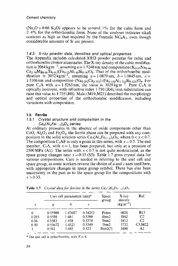
Cement chemistry
(Na2O-f0-66 K2O) appears to be around 1% for the cubic form and2-4% for the orthorhombic form. None of the analyses indicates alkalicontents as high as that required by the formula NC8A3, even thoughconsiderable amounts of Si are present.
1.4.5 X-ray powder data, densities and optical propertiesThe Appendix includes calculated XRD powder patterns for cubic andorthorhombic clinker aluminates. The X-ray density of the cubic modifica-tion is 3064 kg m"3, assuming a = l-5240nm and composition (K0.03Na0.06Ca2.76Mgo.o8Tiooi)(Fe0.22Ali.6oSioi8)06. That of the orthorhombic mod-ification is 3052kgm~~3, assuming <2= l-0879nm, b= 1-0845nm, c =l-5106nm and composition (Nao.292Ca2.792) (Fe0.i5oAli-725Sio.i25)06. Forpure C3A with a=\-5263nm, the value is 3029kgm~3. Pure C3A isoptically isotropic, with refractive index 1-710 (R4); iron substitution canraise this value to 1-735 (H8). Maki (M19,M21) described the morphologyand optical properties of the orthorhombic modification, includingvariations with composition.
1.5 Ferrite1.5.1 Crystal structure and composition in the
Ca2(AlxFe^-x)2O5 seriesAt ordinary pressures in the absence of oxide components other thanCaO, AI2O3 and Fe2C>3, the ferrite phase can be prepared with any com-position in the solid solution series Ca2(ALcFei_JC)2O5, where 0 < x < 0-7.The composition C4AF is only a point in this series, with x — 0-5. The endmember, C2A, with x = 1, has been prepared, but only at a pressure of2500MPa (Al). The series with x<0-l is not quite isostructural, as thespace group changes near x = 0-33 (S5). Table 1.7 gives crystal data forvarious compositions. Care is needed in referring to the unit cell andspace group, as some workers reverse the choice of a and c axes used here,with appropriate changes in space group symbol. There has also beenuncertainty in the past as to the space group for the compositions withx>0-33.
Table 1.7 Crystal data for ferrites in the series Ca2(AlxFe\-x)2O5
X
00-2850-360-501
Unit cell
a
0-559800-55880-55830-556720-541
parameters
b
1-476871-4611-4581-45211-445
(nm)*
c
0-542530-53800-53740-53490-523
Spacegroup
PcmnIbm2Ibm2Ibm2
Ibm2(?)
X-raydensity
(kgm-3)
40263862381237323480
Ref.
B13C2
aC3,M22
Al
* The unit cell is orthorhombic, with Z = 4.
24

Portland cement and its major constituent phases
Plots of unit cell parameters or XRD powder spacings against x for thepure Ca2(Al,Fe)2O5 series (S5) tend to show a change in slope nearx = 0-3, attributable to the structural change. Such plots may be used todetermine composition only if oxide components other than CaO, A12O3and Fe2O3 are absent. They have often been applied to ferrites in clinkers,but this gives seriously inaccurate results because of the effects of othersubstituents (Sections 1.5.2 and 1.5.3).
Biissem (Bll) determined the approximate crystal structure of C4AF.Subsequent determinations or refinements were reported for preparationswith x = 0 (C2F) (B12,B13,C4), x = 0-285 and 0-36 (C2) and x = 0-5 (C3).Figure 1.8 shows the structure for the compositional range with 0-33 <x < 0-7. It is derived from that of perovskite (CaTiO3) by the substitutionof Al and Fe for Ti, together with ordered omission of oxygen atoms,which causes one-half of the sheets of octahedra in perovskite to bereplaced by chains of tetrahedra. The empirical composition may thusbe written Ca2M2T2O5, where M and T represent octahedral and tetra-hedral cations, respectively. The structure for compositions with x < 0-33differs from that shown in Fig. 1.8 in that one-half of the chains of tetra-hedra have the opposite polarity.
Each Ca2+ ion in C4AF has 7 oxygen neighbours at 0-23 to 0-26 nm(C3). The aluminium and iron atoms are both distributed between
o
Fig. 1.8 Crystal structure of C4AF, based on the results of Colville and Geller(C3) and showing calcium atoms (open circles), (Al,Fe)O4 tetrahedra (triangles)and (Fe,Al)O6 octahedra (hatched squares). Heights of atoms are given ashundredths of the cell height (b = 1-452 nm). Atoms at heights outside the range of-1 to +39 are not shown, their positions being derivable from those shown bytranslations of 1/2 parallel to each of the axes.
25

Cement chemistry
octahedral and tetrahedral sites, the fraction of the aluminium enteringtetrahedral sites under equilibrium conditions decreasing with tempera-ture. For the three preparations with x = 0-285, 0-36 and 0-5 on whichX-ray structure determinations were made, 75-76% of the total contentof aluminium was found to be in tetrahedral sites. These prepara-ions were shown to have been in equilibrium at about 750°C (C3); for aC4AF preparation quenched from 1290°C, the Mossbauer spectrumindicated that only 68% of the aluminium was in tetrahedral sites (G10).It was suggested that x does not exceed the observed limit of about 0-7because at this composition the tetrahedral sites are all occupied byaluminium (C2). There is evidence of clustering of aluminium and ironatoms to an extent depending on composition and conditions offormation (Zl).
1.5.2 Compositions of clinker ferritesIn many clinkers, the ferrite is closely mixed with aluminate; due to asimilarity in cell parameters, oriented intergrowth can occur (M21). Theclose admixture often renders X-ray microanalysis difficult or unreliable.For ordinary Portland cement clinkers, the compositions found indifferent laboratories are nevertheless remarkably consistent. They showthat there is little or no substitution for Ca2+, the substituent ions beingcontained essentially in the octahedral and tetrahedral sites. Table 1.2includes an average value based on the results of investigations usingX-ray microanalysis (B2,B3,H3,H9,K1,S6,U2) or chemical analysis ofseparated material (Yl). Table 1.3 includes suggested site occupanciescorresponding to these data. Data on the distribution of substituentsbetween octahedral and tetrahedral sites (Z2) are insufficient to justify adistinction between them, as the preferences of some of the cations,especially Mg2+, in this structure are unknown, as is the temperature atwhich equilibrium is attained. This temperature probably varies betweenclinkers, and may be expected to affect the distribution.
The typical composition differs markedly from that of C4AF(46-1% CaO, 21-0% AI2O3, 32-9% Fe2O3). It contains about 10% ofsubstituent oxides and is much lower in Fe2O3. It approximates toCa2AlFeo6Mgo.2Sio.15Tio.05O5, which is derived from that of C4AF byreplacing some of the Fe3+ by Mg2+ and an equal amount by Si4+ andTi4+. A conclusion (N5) based on Rietveld analysis of the XRD powderpattern that Si4+ is not present in solid solution but in closely admixedbelite appears incompatible with the observation that incorporationof Si4+ markedly affects the colour and electrical conductivity (15). AMossbauer study also provided indirect evidence for silicon substitu-tion (Z2).
Sulfate-resisting Portland cement clinkers, including those made foruse in oil well cements, have relatively high ratios of Fe to Al, and if it isassumed that most of the iron is in the ferrite, the latter cannot have thecomposition given above. X-ray microanalyses (B14,G3-G5,H6,R6)indicate that, in contrast to the situation in normal Portland cementclinkers, there is substantial replacement of Al3+ as well as, or even
26

Portland cement and its major constituent phases
instead of, Fe3+ in the C4AF composition. Microanalyses show that thereis much variation in composition, both between clinkers and withinclinkers, especially at the micrometre level that can be studied using TEM(R6). The mean contents of MgO and Fe2O3 are related to those of theclinker, and the SiO2 content tends to increase with that of MgO; SO3
contents of up to 0-9% have been reported (B14, H6). The Al2O3/Fe2O3ratio is probably also related to that in the clinker. Tables 1.2 and 1.3include what is possibly a typical mean composition and atomic ratioscalculated from it.
1.5.3 Crystal data and X-ray powder patterns for ferrites containingsubstituent ions
Mn3+ can replace all the Fe3+ or up to 60% of the Al3+ in C4AF (K3).Yamaguchi and Takagi (Yl) summarized data showing that incor-poration of Mg2+ or Si4+ or both causes increases in cell parameters.Boikova (B2) determined the cell parameters of four preparationswith compositions similar to those of typical clinker ferrites; the rangeswere a = 0-5535-0-5554 nm, b = 1 -4492-1 -4642 nm, c = 0-5288-0-5333 nm.Marinho and Glasser (M23) found that Ti4+ substitution caused stackingchanges in C2F or C4AF. It had negligible effect on the cell parameters andthe charge was balanced by incorporation of additional oxygen atoms.This last conclusion may be irrelevant to clinker ferrites, since Ti4+ is arelatively minor substituent and the charge can be balanced in other ways.
Regourd and Guinier (Rl) reported unit cell parameters for the ferritein five clinkers. The ranges observed were a — 0-5517-0-5555 nm,6 = 1455-1462 nm, c = 0-5335-0-5350 nm. Boikova (B2) reported XRDpowder spacings for clinker ferrites which indicate similar values. Thesimilarity of these cell parameters to those of the laboratory preparations(B2) mentioned in the previous paragraph supports the results of X-raymicroanalyses of clinker ferrites described in Section 1.5.2. Comparedwith pure C4AF, typical clinker ferrites have smaller values of a and c,but larger values of b.
The XRD powder patterns of clinker ferrites are affected by thecooling rate (I4,M24,O2). The effect is associated with differing uptake ofMgO and SiO2. Extreme values of the cell parameters were a = 0-557 nm,Z>=1462nm, c = 0-532 nm for a quenched sample, and a = 0-543 nm,6=1465nm, c — 0-533 nm for one that was slowly cooled (O2). Theferrite in the quenched samples was poorly crystalline, many peaks otherthan the three most intense (200, 141 and 202) disappearing (O2).Broadening of peaks of clinker ferrites (B2,M24,R1) might be caused notonly by poor crystallinity, but also by zoning. The cell parametersobserved by Regourd and Guinier (Rl) and Boikova (B2) are near tothose of the quenched sample.
The Appendix includes a calculated powder pattern for a ferrite havingcell parameters and composition similar to those for the material in typi-cal clinkers The X-ray density, assuming a = 0-5535nm, 6=14642nm,c = 0-5328nm and composition Ca2AlFe0.6Si0 15T10.05O5, is 3570kgm~3.
27

Cement chemistry
1.5.4 Optical, magnetic and other dataFerrite of or near C4AF composition and free from substituent ions isyellowish brown in transmitted light. The optical properties of C4AF areas follows: biaxial, negative, with moderate 2V; a 1-96, /3 2-01, 7 2-04 inlithium light; pleochroic, with 7 brown, a yellowish brown; the refractiveindices increase with Fe/Al ratio (H8). The optic orientation is X=b,Y—c, Z = a (M25). The pleochroism of ferrite solid solutions has beenstudied (M25).
If clinker ferrites are cooled in air, they are commonly almost black.The dark colour is associated with markedly higher electrical conductiv-ity (I5,M24). In the absence of other substituents, it arises if the ferritecontains an excess of small dipositive ions (Mg2+ or Zn2+) over tetra-positive ions (Si4+ or Ti4+) and is cooled in air (15). If the substitutedferrite is cooled in N2 or quenched in water, the dark colour disappears(M24). Its disappearance seems to be due to the absence of Fe4+ ratherthan the presence of Fe2+ (M25,S7). An excess of dipositive over tetra-positive substituents when all the iron is present as Fe3+ implies thepresence of oxygen vacancies; these can be filled during cooling, withconcomitant oxidation of a little of the iron to Fe4+. Clinker ferrites canapparently be dark even if there is not an excess of dipositive overtetrapositive substituents. This has yet to be explained.
The ferrite is ferromagnetic, and the more iron-rich members of theCa2(AlJCFei_x)2O5 series have been studied for their magnetic properties,especially in regard to the coordinations of the Fe atoms (C4,G11).Ferrite with a composition near C4AF has been found in nature. Thename brownmillerite, already in use in cement chemistry, was adopted asthe mineral name (G7).
28

2 High-temperature chemistry
2.1 IntroductionA knowledge of the relevant high-temperature phase equilibria is necessaryfor understanding the factors that govern acceptable bulk compositionsfor Portland cement clinker, the conditions under which the latter canbe manufactured, and the phase composition and microstructure ofthe resulting material. This chapter deals with these equilibria and with thephases to which they relate, with the exception of the major clinker phases,which were described in Chapter 1. Some anhydrous phases primarily ofinterest in relation to other types of cements are also considered here.Principles underlying the preparation of anhydrous silicate, aluminate andother high-temperature phases are outlined.
2.2 Systems containing CaO with SiO2 or AI2O3 or both2.2.1 The CaO-SiO2 systemFigure 2.1 shows the phase diagram. For clarity, the polymorphism of C3Sand the distinction between a'H- and a'L-C2S are omitted. Calcium oxide(CaO) has the sodium chloride structure, in which all ions are octahedrallycoordinated; the unit cell is cubic, with a = 0-48105 nm, space groupFm3m, Z = 4, Dx = 3345 kgm~3 (S8). The refractive index is 1-837 (W3).
On equilibrium cooling below 1250°C, C3S decomposes to give CaOand af
H-C2S; this process, which is always slow and below 700°C imper-ceptible, is considered in Section 3.5.5. /3-CS, a-CS and C3S2 arecommonly known by their mineral names of wollastonite, pseudowollas-tonite and rankinite, respectively; none reacts significantly with water atordinary temperatures. The crystal structures of /3-CS (O4) and a-CS (Y3)differ markedly from each other and the two polymorphs are easily dis-tinguishable by powder XRD. Both exhibit polytypism (/3-CS (H1O,H11);a-CS (Y3)); the polytypes of a given polymorph are barely distinguish-able by this method. The name 'parawollastonite' has been used forthe 2M polytype of /3-CS. The /3-a transition is reversible but slow in thea to (3 direction, rendering a-CS easily preservable by quenching. Thestructure of rankinite is known (S9); a polymorph, kilchoanite, is knownonly as a natural mineral and as a product of hydrothermal reactions.
The polymorphs of silica relevant to cement chemistry are brieflyconsidered in Section 3.3.2.
29
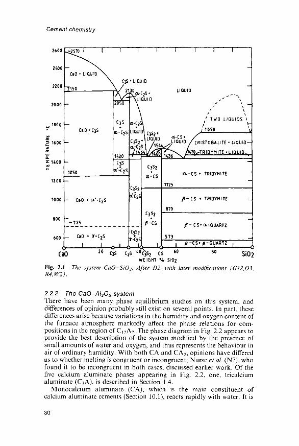
Cement chemistry
2600
2400 -
a-cs* /IQUID /CRISTOBALITE* LIQUID —
600 _
CaO 20 C3S c2s " c N3 s 2 cs 60 80 S J 0 2
WEIGHT % SiO2
Fig. 2.1 The system CaO~SiO2. After D2, with later modifications (G12,O3,R4,W2).
2.2.2 The CaO-AI2O3 systemThere have been many phase equilibrium studies on this system, anddifferences of opinion probably still exist on several points. In part, thesedifferences arise because variations in the humidity and oxygen content ofthe furnace atmosphere markedly affect the phase relations for com-positions in the region of Ci2A7. The phase diagram in Fig. 2.2 appears toprovide the best description of the system modified by the presence ofsmall amounts of water and oxygen, and thus represents the behaviour inair of ordinary humidity. With both CA and CA2, opinions have differedas to whether melting is congruent or incongruent; Nurse et al. (N7), whofound it to be incongruent in both cases, discussed earlier work. Of thefive calcium aluminate phases appearing in Fig. 2.2, one, tricalciumaluminate (C3A), is described in Section 1.4.
Monocalcium aluminate (CA), which is the main constituent ofcalcium aluminate cements (Section 10.1), reacts rapidly with water. It is
30

High-temperature chemistry
WEIGHT %
Fig. 2.2 The system CaO-Al2O3 modified by the presence of small amountsof H2O and 02, and thus representing the behaviour in air of ordinary humidity.After R4, with later modifications (C5,N6,N7).
monoclinic and pseudohexagonal, with a = 0-8700 nm, b = 0-8092 nm,c= 1-5191 nm, /3 = 90-3°, space group Pl^/n, Z = 1 2 , Dx = 2945 kgm"3,and has a stuffed tridymite structure, composed of Ca2+ ions and aninfinite, three-dimensional framework of A1O4 tetrahedra sharing corners(HI2). It crystallizes as irregular grains, sometimes prismatic and oftentwinned, with a = 1-643, (5 = 1-655, 7 = 1-663, ( - )2F=36° (R4). Forma-tion from CaCO3 and A1(NO3)3 in the presence of organic reducingagents is reported to proceed through an amorphous material at 500°Cand an orthorhombic polymorph at 850°C (B15).
Calcium dialuminate (CA2) occurs in some calcium aluminate cements.It reacts only slowly with water. The formula was at one time wronglyconsidered to be C3A5. CA2 is monoclinic, with a —1-28398 nm,b = 0-88624nm, c = 0-54311 nm, /3= 106-8°, space group C2/c, Z = 4,Dx — 2920 kg m~3, and has a structure based on a framework of A1O4
tetrahedra, in which some oxygen atoms are shared between two, andothers between three tetrahedra (B16,G13). It crystallizes as laths orrounded grains, with a = l-6178, /?= 1-6184, 7=1-6516, (+)2K=12°(B16). CA2 has been found as a natural mineral (G7).
Calcium hexaluminate (CA6) melts incongruently and does not reactwith water at ordinary temperatures. Its crystal structure is closely relatedto those of corundum and /?-Al2O3.
2.2.3 C12A7 and derived structuresIn air of ordinary humidities, a phase of approximate composition Ci2A7
is readily formed. It reacts rapidly with water and occurs in some calcium
31
Cement chemistry
aluminate cements. A related phase, C n A 7 -CaF 2 , is similarly reactiveand occurs in certain special cements. In early work, Ci2A7 was wronglyassigned the formula C5A3 and called 'stable C5A3' to distinguish it fromanother phase of that composition, described below, which was called'unstable C5A3'. Ci2A7 is cubic, with a= 11983nm (J3), space groupI43d and Z = 2 (Bll). Studies on C12A7 or closely related phases(B17,B18,F6,W4,W5) show the crystal structure to be built from Ca2+
ions, an incomplete framework of corner-sharing A1O4 tetrahedra andempirical composition Al7O}g~, and one O2~ ion per formula unitdistributed statistically between 12 sites.
At temperatures above about 930°C, a reversible equilibrium existsbetween Q 2 A 7 and water vapour in the furnace atmosphere (J3,N6,N8,R7). Material prepared in ordinary air and quenched from 1360-1390°C is almost anhydrous; on being gradually reheated, it takes upwater until at 950°C a maximum content of about 1-3% is attained,corresponding to the formula C12A7H. On further increase in tempera-ture, the water is lost again, until by the melting point in the region of1400°C the material is almost anhydrous. The sorbed water affects thecell parameter and refractive index. There was early disagreement as tothe direction of the variations, but it appears established that Ci2A7H hasthe smaller cell parameter and higher refractive index, Jeevaratnam et al(J3) finding a=l-1983nm, n= 1-611 and Dx = 2680kgm~3 for C12A7
and a= 1-1977, n= 1-620 and Dx = 2716kgm~3 for Ci2A7H.Jeevaratnam et al. (J3) suggested that Ci2A7 can take up water because
the 12 sites per formula unit that are occupied statistically by one O2~ ioncan alternatively be occupied by two OH" ions, Ci2A7H thus having theconstitution Ca6Al7Oi6(OH). In support of this conclusion, they preparedthe halide analogues CnA 7 -CaF 2 and CnA7«CaCl2 of the latter com-pound. CnA7*CaF2 was found to have a cell parameter of M964nm,giving Dx = 2732 kg m~3. It forms a continuous range of solid solutionswith Ci2A7 (S10). Bromide, iodide, and sulfide analogues (T1,Z3) anda chloride analogue with partial replacement of Al by Si, balanced byadditional occupancy by Cl of the statistically available sites (F6), havealso been described.
Imlach et al. (16) found that they could prepare C12A7 reproducibly byslowly cooling melts in dry oxygen and that samples obtained in this way, orby cooling melts in moist air, contained excess oxygen, which could bedetected chemically and was possibly present as peroxide ion. If similarmelts were cooled in very dry nitrogen, mixtures consisting of CA, C3A and,sometimes, C5A3 were obtained, with only poor yields of Ci2A7. Theseobservations have since been confirmed and extended (B19,B20,Z3,Z4).
Zhmoidin and Chatterjee (Z3,Z4) concluded from density, viscosityand mass spectrometric evidence that melts of C!2A7 composition con-tained regions of two kinds, differing in structure and density. Theproportion of the less dense regions increased if the melt took up H2O,O2, CO, CO2 or SO3, or if CaF2, CaCl2, CaS, CaSO4, or CaCO3 wasadded; if this proportion was sufficiently high, C12A7 or a derivativewas formed on freezing. The proportion of the denser regions in the
32

High-temperature chemistry
melt was increased by maintaining a dry and slightly reducing atmo-sphere and by increase in temperature; if the less dense regions were thuseliminated, the melt yielded a homogeneous glass on quenching, or C5A3
on slow cooling. The molecules that stabilized the less dense regions actedby surrounding themselves with a particular type of open structure, fromwhich C12A7 readily nucleated; analogies were noted with the roles ofhydrated alkali cations in the formation of zeolites and of water ororganic molecules in that of compounds of the noble gases. With theexception of water, the molecules thus occluded in crystalline C12A7could not be removed without destroying the structure. C12A7 melts areconsiderably denser (2870-2910 kg m~3) than solid Ci2A7, especially ifthey have been kept in reducing atmospheres.
The derivatives of Ci2A7 melt in normal ways, CnA 7 -CaF 2
congruently at 1577°C and CnA7«CaS incongruently to give CaS andliquid at 1482°C (Z3). In contrast, Q 2 A 7 stabilized only by water showsanomalous behaviour, one study (N8) showing a sharp melting point of1392°C over a range of compositions, and another (S10,Z3) melting overa range from 1380 to 1415°C with evolution of gas and incipient for-mation of CA, C3A and C5A3. Figure 2.2 is thus approximate in thisregion. For practical purposes, the situation in air of ordinary humiditiesis more important than that in very dry and oxygen-free atmospheres,and the primary phase field of Q 2 A 7 will be included in the relevantternary and quaternary phase diagrams presented below.
Ci2A7 or Ci2A7H has been found as a natural mineral and namedmayenite (G7,H13).
2.2.4 C5A3, C2A and C4A3
The conditions of formation of C5A3 are discussed in the preceding section;it is probably an equilibrium phase in the strictly binary system CaO-Al2O3
but does not form in atmospheres of normal humidity and oxygen content.C5A3 is orthorhombic, with a= M253nm, b = 10966nm, c= 10290nm,space group Cmc21? Z = 4, Dx = 3067 kgm~3, and a structure related tothat of gehlenite (VI). The density is considerably higher than that of Ci2A7
and accords with the formation of the compound from the denser regionspresent in the melt. C5A3 reacts rapidly with water (B21).
Two other anhydrous calcium aluminates are known. C2A, a high-pressure phase, is described in Section 1.5.1. C4A3 is formed as thedehydration product of a hydrothermally produced phase, C4A3H3. Itsstructure is similar to that of sodalite (Na4(Al3Si3Oi2)Cl); the constitu-tional formula is Ca4(Al6O12)O (P3).
2.2.5 The CaO-AI2O3-SiO2 systemThe phase diagram was originally determined by Rankin and Wright(R4). Figure 2.3 is based on that of Muan and Osborn (M26), withfurther amendments mainly following from studies on the boundingCaO-SiO2 and CaO-Al2O3 systems discussed in the preceding sections. Itrelates to atmospheric pressure in an atmosphere of normal humidity, theprimary phase field of Ci2A7 thus being shown. Some phases probably
33

Cement chemistry
TWOL I Q U I D S
Fig. 2.3 The system CaO-Al2O3-SiO2. Aft
1BM)
ter M26, with later modifications.
form solid solutions within the system, C3S, for example, being able toaccommodate some A12O3; this is not shown.
Two ternary compounds exist stably in the system under these condi-tions. Gehlenite (C2AS; Ca2Al2Si07) belongs to the melilite family. In itsstructure, layers of 8 coordinated Ca2+ ions alternate with ones of com-position Al2SiOy~, in which both aluminium and silicon are tetrahedrallycoordinated (L3). Gehlenite forms extensive solid solutions, e.g. withakermanite (C2MS2; Ca2MgSi207). In a modified form, it occurs insome calcium aluminate cement clinkers (Section 10.1.2),. It is tetra-gonal, with a — 0-7716 nm, c — 0-5089 nm, space group P42im, Z = 2,At = 3006 kg m3" (L3) and refractive indices a; =1-669, e= 1-658 (W3).The unsubstituted compound does not appear to react with water atordinary temperatures, but the Al-rich variety present in calciumaluminate cements shows some reactivity at 40°C (SI 1). Anorthite (apolymorph of CAS2; CaAl2Si2O8), which is less relevant to cementchemistry, is a triclinic felspar.
Several other anhydrous calcium aluminosilicates are known, includinggrossular or garnet (C3AS3), which is a high-pressure phase, variousdehydration products of zeolites, and various products formed metastablyby crystallization from melts or glasses. Most are too acid in composition
34

High-temperature chemistry
to be of clear relevance to cement chemistry, but some of the devitrifica-tion products, especially those with compositions near CA and structuressimilar to those of nepheline (Na3KAl4Si4Oi6) or kalsilite (KAlSiO4)(Y4) are of possible interest in relation to the formation of calciumaluminate cements.
2.2.6 Clinker formation in the CaO-AI2O3-SiO2 systemThe CaO-Al2O3-SiO2 diagram provides a basis for a preliminaryunderstanding of the chemistry underlying the formation of Portlandcement clinker, in which all but the three most important oxide com-ponents are ignored. The approximations are least for white cements. In acement kiln, the maximum temperature reached by the mix, called theclinkering temperature, is commonly 1400-1450°C; at this temperature,the mix is partly molten. For a mix in the pure CaO-Al2O3-SiO2 system,a somewhat higher temperature is required to give a comparablesituation. In this discussion, it is assumed that equilibrium is attainedat a clinkering temperature of 1500°C and the CaO-Al2O3-SiO2 diagramis used to predict which solid phases will be present for various bulkchemical compositions. The processes by which this equilibrium isapproached in cement making, and those taking place during the sub-sequent cooling, are discussed in Chapter 3.
The compositions in the pure CaO-Al2O3-SiO2 system that corre-spond most nearly to those of typical Portland cement clinkers lie withinthe ringed area surrounding point P in Fig. 2.4. This point lies within thetriangle whose apices are the compositions of C3S, C2S, and point X,which lies at the intersection of the boundary of the C3S and C2S primaryphase fields with the 1500°C isotherm. For any bulk composition in this
Fig. 2.4 Part of the system CaO~Al2O3-SiO2, illustrating the formation ofPortland cement clinker; for significance of lettered points and of thin full or brokenlines, see text.
35

Cement chemistry
triangle, the equilibrium phases at 1500°C will be C3S, C2S and liquid ofcomposition X. This may be understood by considering what happensif a melt of composition P is cooled. C3S first crystallizes, the liquidcomposition thus moving away from that of C3S until the boundarybetween the primary phase fields of C3S and C2S is reached. C3S and C2Sthen both crystallize, and the liquid composition moves along thisboundary until the 1500°C isotherm is reached. For the conditions thatexist in cement making, the entire mix is never molten, so that the path toequilibrium differs, but the resulting phase assemblage must be the same.The crystals of C3S and C2S, being in contact with the melt, can grow torelatively large dimensions, which are typically around 30 fim. During thesubsequent cooling the liquid solidifies, producing the more finely grainedinterstitial material.
Some other bulk compositions may be considered in the same way.A composition such as Q, lying within the triangle C2S-X-Y, will atequilibrium at 1500°C give C2S and a liquid having a composition on thecurve XY. One such as R, in the triangle C3S-X-Z, will give C3S and aliquid having a composition on XZ. Any composition lying below the lineC3S-Z, such as S, will give an assemblage that includes calcium oxide as asolid phase.
In making Portland cement clinker, it is essential to avoid the presenceof more than minimal amounts of free calcium oxide in the final product,and normally desirable to maximize that of C3S. If equilibrium werecontinuously maintained during cooling, apart from decomposition ofC3S into C2S and calcium oxide at sub-solidus temperatures, any bulkcomposition lying within the triangle C3S-C2S-C3A would yield a finalproduct consisting of these three phases. For bulk compositions belowthe line C3S-Z, this would require that the crystals of calcium oxidepresent at the clinkering temperature be redissolved. This process is slow,and one cannot assume that it will be substantially completed in theconditions existing in the kiln. The line C3S-Z therefore sets a practicallimit to the CaO content of the mix. For the temperature range in whichclinkering is practicable, it virtually coincides with a line joining the C3Scomposition to the invariant point at 1470°C involving calcium oxide,C3S, C3A and liquid, and that line may therefore be used to define theupper limit of acceptable CaO contents. This approach, modified asdiscussed in Section 2.3.3 to allow for the presence of Fe2O3, leads to thedefinition of a quantity called the lime saturation factor, which can beused in practice as an important parameter of the bulk chemicalcomposition.
2.3 Systems containing Fe2O3
2.3.1 The CaO-AI2O3-Fe2O3 systemThis system includes the Ca2(AlxFei_x)2O5 series of ferrite compositions.The bounding, binary system CaO-Fe2O3 includes three compounds, viz.C2F, CF and CF2. C2F, as an end member of the above series, isdiscussed in Section 1.5. The other two compounds are of lesser import-ance to cement chemistry. Phillips and Muan (P4), in a study of the
36

High-temperature chemistry
binary system, found that CF melted incongruently at 1216°C to giveC2F and liquid, and that CF2 decomposed at 1155°C to give CF andhematite (a-Fe2O3). In this and other systems containing Fe2O3, iron-richmixes tend to lose oxygen when heated in air above 1200-1300°C, withconsequent replacement of hematite by magnetite (Fe3O4). At lowerpartial pressures of oxygen, such as occur in a cement kiln, oxygen loss issignificant even with compositions relatively low in iron.
Figure 2.5 shows part of the ternary system, CaO-Al2O3-Fe2O3. C3A,C12A7 and CA can all accommodate some Fe3+; for C3A underequilibrium conditions at 1325°C, the limit is about 4.5%, expressed asFe2O3 (M27). The ferrite phase in equilibrium with Fe-substituted C3Acan have compositions with x between 048 and 0-7 in the formulaCa2(AlxFei_x)2O5; if CaO is also present, x is fixed at 048, i.e. thecomposition is close to C4AF. Some reduction of Fe3+ to Fe2+ occurswhen the ferrite phase is prepared from mixes with compositions in theCa2(AlxFei_x)2O5 series in air; it leads to the formation of minoramounts of other phases, which are not observed when similar experi-ments are carried out in oxygen (M27).
CA
1390C12A7
K 0 0
1542,
C3A
Fig. 2.5 Part of the system CaO-Al2O3~Fe2O3. Hatched lines indicate solidsolutions. Ferrite phase compositions are indicated by the quantity x, which relatesto the formula Ca2(AlxFe1_x)2O5. After N9 and M27.
37

Cement chemistry
Swayze (SI2) noted that equilibrium was often difficult to achieve inthis system. One effect was the tendency for crystals of the ferrite phase tobe zoned. For bulk compositions in the Ca2(AlxFei_x)2O5 series, theliquid is of higher Al/Fe ratio than the ferrite phase with which it is inequilibrium; the crystals that are initially deposited on cooling such aliquid therefore have a lower Al/Fe ratio than the bulk composition ofthe mix. On further cooling, the Al/Fe ratio of the material depositedprogressively increases. Equilibrium within the ferrite crystals is difficultto attain, causing them to remain zoned, with cores richer in Fe3+ andouter regions richer in Al3+ than the mean composition.
A second effect was the tendency for protected phases to be formed. Ifa liquid having a composition somewhat on the CaO-rich side of theboundary between the CaO and C3A primary phase fields (Fig. 2.5) iscooled, calcium oxide is initially deposited and the liquid compositionmoves away from CaO and towards that boundary. When the latter isreached, and assuming that equilibrium were to be maintained, calciumoxide would redissolve, C3A would be deposited, and the liquid com-position would move along the boundary. In reality, the C3A quicklysurrounds the particles of calcium oxide, which thus becomes a protectedphase, effectively removed from the system. This can markedly affectthe composition of the ferrite phase which is subsequently formed onfurther cooling.
2.3.2 The CaO-AI2O3-Fe2O3-SiO2 systemThis system comprises the four major oxide components of Portlandcement. Lea and Parker (L4,L5) made a classic study of the subsystemCaO-C2S-C12A7-C4AF, which is the part directly relevant to cementproduction. Following Lea (L6), the formula Ci2A7 is substituted in thepresent description of this and related investigations for C5A3, which wasused by the original authors in accordance with contemporary opinion onthe composition of the phase now regarded as Ci2A7. Any errors arisingfrom this compositional difference will be small. Lea and Parker assumedthe ferrite phase to have the fixed composition C4AF.
Lea and Parker began by studying the bounding ternary subsystemsCaO-C2S-C4AF and Ci2A7-C2S-C4AF. The first of these, which is themore important, is shown in Fig. 2.6, modified in accordance with laterwork on the CaO-SiO2 system. In general form, it resembles the lime-richcorner of the CaO-Al2O3-SiO2 system (Fig. 2.4), with C4AF in place ofC3A, the primary phase field of C3S thus being an elongated areaextending away from the CaO-C2S edge of the diagram.
The quaternary system may be represented on a tetrahedral model, eachface of which represents one of the bounding, ternary systems. Within thetetrahedron, primary phase fields and sub-solidus compatibility assem-blages are represented by volumes, corresponding to the respective areason the triangular diagram of a ternary system; correspondingly, isothermsare represented by surfaces. Figure 2.7 shows some important features ofthe CaO-C2S-Ci2A7-C4AF subsystem, as found by Lea and Parker andmodified to take account of later work (G12,M27,N9,S12,S13,W2).
38

High-temperature chemistry
2130Q C2S
2570
1 3 9 5CaO " C4AF
Fig. 2.6 The system CaO~C2S-C4AF. After L4, with later modifications.
CaO 1542 C12A7
Fig. 2.7 The pseudosystem CaO-C2S-C' 12A7-C4AF\ showing the primary phasevolume ofC3S. For details of invariant points P1-P8, see Table 2.1. After L4, withlater modifications.
39

Cement chemistry
No quaternary compounds exist in this subsystem. The tetrahedron cantherefore be divided into three smaller ones representing sub-solidus com-patibility assemblages for CaO-C3S-C3A-C4AF, C3S-C3A-C2S-C4AFand C12A7-C3A-C2S-C4AF. For clarity, these are not shown on Fig. 2.7.The most important feature of the subsystem is the primary phase volumeof C3S, which is a thin sliver, roughly parallel to the C2S-C12A7-C4AFface of the tetrahedron and sandwiched between the larger phase volumesof CaO and C2S. In accordance with the bounding subsystems (Figs 2.4and 2.6), two of its edges lie on the CaO-C2S-C4AF and CaO-C2S-C12A7 faces of the tetrahedron, but it cannot extend to the CaO-C4AF-C12A7 face. Table 2.1 gives details of the eight invariant points involvingC3S in this subsystem.
Subsequent studies on the CaO-Al2O3-Fe2O3 (M27,N9) and CaO-Al2O3-Fe2O3-SiO2 (SI2,SI3) systems have extended knowledge of thelatter to a wider range of compositions, but have only slightly affectedconclusions regarding the phase volume of C3S. All indicate that thephase volume of C3A is larger, and that of the ferrite phase smaller thanwas shown in Lea and Parker's diagrams, which in this region partlyrested on early results for the CaO-Ci2A7-C4AF system. To simplify thediagram, the volumes of phases other than C3S are indicated only ingeneral terms on Fig. 2.7.
2.3.3 Clinker formation in the CaO-AI2O3-Fe2O3-SiO2 systemLea and Parker (L5) derived a formula giving the maximum acceptablecontent of CaO in a Portland cement clinker composition. If equilibriumwas maintained during cooling, apart from decomposition of C3S intoC2S and CaO at sub-solidus temperatures, any bulk composition withinthe tetrahedron C3S-C2S-C3A-C4AF would yield a clinker consisting ofthose four phases. However, as in the CaO-Al2O3-SiO2 system, it cannotbe assumed that any calcium oxide present at equilibrium at the clinker-ing temperature will subsequently be reabsorbed. Following reasoningsimilar to that in Section 2.2.6, calcium oxide will not be present atequilibrium at the clinkering temperature of approximately 1450°C ifthe bulk composition lies on the lime-poor side of a plane defined by thecompositions of C3S, C4AF and the invariant point P3 (Fig. 2.7 andTable 2.1). The oxide ratios by mass for these three compositions aregiven in Table 2.2. One may then set up three simultaneous equations ofthe type
(SiO2/CaO);c + (Al2O3/CaO).y + (Fe2O3/CaO)z =1-0 (2.1)
where chemical formulae represent mass percentages of oxides in theclinker, and solve them to obtain an expression for the content of CaO atany point in the plane, viz.
CaO = xSiO2 + J>A12O3 + zFe2O3 (2.2)
This gives x = 2-80, y= 1-18, z = 0-65.The ratio [CaO/(2-80SiO2+ M8Al2O3 + 0-65Fe2O3)] is called the lime
saturation factor (LSF). A mix having an LSF greater than unity will
40

Tab
le 2
.1
Inva
rian
t po
ints
inv
olvi
ng C
3S i
n th
e C
aO~A
l 2O
3-F
e 2O
3-Si
O2
syst
em a
nd i
n th
e sa
me
mod
ifie
d by
5%
M
gO
Poi
nt
PI
P2 P3 P4 P5
P6
P7
P7
P7
P8 P8 P8 * x
in
Solid
pha
ses
in a
ddit
ion
to C
3S
CaO
C2S
CaO
+ C
3AC
2S +
C3A
CaO
+ f
erri
teC
2S +
fer
rite
CaO
+ C
3A +
fer
rite
CaO
+ C
3A +
ferr
ite
CaO
+ C
3A +
fer
rite
+ M
gOC
2S +
C3A
+ f
erri
teC
2S +
C3A
+ f
erri
teC
2S +
C3A
+ f
erri
te +
MgO
form
ula
Ca 2
(Al J
CF
ei_ x
) 2O
5.t E
= e
utec
tic; P
= p
erite
ctic
.
CaO
71-5
69-5
59-7
58-5
52-8
52
45
50
53-9
50-9
54-8
53-5
50-5
Liq
uid
com
posi
tion
A1 2
O3
_ _32
-832
-916
216
-322
-721
-222
-722
-722
-323
-9
Fe 2
O _ — —2
54
25-5
16-5
191
15-8
16 5
18-2
14-7
(mas
s pe
r ce
nt)
3 S
iO2
MgO
28-5
30-5 7-5
8-6
5-6
5-8
5-8
5-8
5-6
<5
06
06
05-
9 <
50
JC in
fer
rite
phas
e*
_ — — -0-
500-
500-
500
44
04
70-
500-
570-
67
Typ
e of
poin
tf
P E P P E P P P P 7 P P
Tem
p-(°
C)
2150
2050
1470
1455
1347
1348
1341
1342
1305
1338
1338
1301
Ref
.
G12
G12
R4
R4
L4
L4
L4
S12
S14
L4
S12
S14
CD CD ature chem is

Cement chemistry
Table 2.2 Oxide ratios by mass for points on the surface bounding theregion in which calcium oxide is an equilibrium phase at 1450°C
Point on surface SiO2/CaO Al2O3/CaO Fe2O3/CaO
C3S 0-357 0 0C4AF 0 0456 0-714P3 0126 0-549 0
yield free calcium oxide at the clinkering temperature, and this phase isliable to persist in the final product, irrespective of the degree of mixing ofthe raw materials and the time during which the clinkering temperature ismaintained. The calculation is approximate, because of the neglect ofminor oxide components and of ionic substitutions in the solid phasesand for other reasons. For values below unity, the LSF provides ameasure of the extent to which the maximum attainable content of C3S isapproached. Values of 0-92-0-98 are typical of modern clinkers.
Lea and Parker considered that their calculations were valid only forAl2O3/Fe2O3 mass ratios in the clinker above that in C 4 AF (0-64), butthis does not appear to be correct (W6). The plane within the C a O - C 2 S -C12A7-C4AF tetrahedron denned by the compositions of C3S, C 4 AFand the point P 3 passes close to the composition of C2A, and thereforealso to all other compositions in the Ca2(AlxFei_x)2O5 series. Swayze's(SI2) results, discussed in Section 2.4.2, show that the extension of theC a O - C 3 S boundary surface to more iron-rich compositions remainsclose to this plane, which therefore serves also for Al2O3/Fe2O3 ratiosbelow that in C 4 AF.
2.4 Systems containing MgO or FeO2.4.1 GeneralPortland cement raw materials contain small proportions of MgO; asnoted in Section 1.1.2, they must be limited to avoid formation of morethan a minor amount of periclase. The iron in Portland cement clinkers isnormally present almost entirely as Fe3+, but calcium aluminate cementsmay contain both Fe3+ and Fe2+.
Table 2.3 lists some phases containing MgO that are in varying degreesrelevant to cement chemistry. It is not a complete list of phases withessential MgO in the CaO-MgO-Al2O3-SiO2 system. As seen in Chapter1, some MgO is also taken up by all four of the major clinker phases.Magnesium oxide (periclase), like calcium oxide, has the sodium chloridestructure; it is cubic, with a = 0-4213 nm, space group Fm3m, Z = 4,Dx = 3581 kgm3" (S8) and refractive index 1-7366 (W3). FeO (wiistite) hasthe same structure, but always contains some Fe3+, balanced by vacancies.It forms extensive solid solutions with MgO and can also accommodatesome CaO.
Early studies of such systems as MgO-C2S-C12A7 (H14), CaO-MgO-C2S-Ci2A7 (M29) and MgO-C4AF (17) indicated that periclase is the
42

High-temperature chemistry
Table 2.3 Some phases containing Mg relevant to cement chemistry
Name
Periclase
ForsteriteMonticellite
MerwiniteBredigite
Akermanite
EnstatiteDiopside
Spinel
'Phase Q'
Formula
MgO
M2S 1C M S /
C3MS2 \C7MS4 J
C2MS2
MS \CMS2 J
MA
C3A2M 1C7A5M (?) )C2oA13M3S3 J
Structure type
Sodium chloride
Olivine
Related to alkali sulfate structures*
Melilite (C2AS etc.)
Pyroxenef
Spinel
Related to C2AS and C5A3t
*'Phase T', of approximate composition Cj.7M0.3S (G14,S15-S17), is identical withbredigite (B9.M28).f Also, the MS polymorphs clinoenstatite and protoenstatite, which, too, are of pyroxenetype.JFor references and descriptions, see Section 2.4.3. Phase Q is of variable composition; theformula given is a median.
only phase with essential MgO liable to be formed in Portland cementclinkers. A later study on the CaO-MgO-Al2O3-SiO2 system suggestedthat bredigite and 'phase Q' could possibly occur in rapidly cooledclinkers (B9), but there is no convincing evidence that either of thesephases is present in production clinkers.
Allen and Snow (A2) studied equilibria in the low-SiO2 part of theCaO-'FeO'-SiO2 system in the presence of metallic iron. The results arerelevant to the formation of Portland cement clinkers under reducingconditions.
2.4.2 Effect of MgO on equilibria in theCaO-AI2O3-Fe2O3-SiO2 system
Swayze (S12,S14) extended the work of Lea and Parker (L4,L5) byconsidering the effects of variable ferrite composition and of the presenceof MgO as an oxide component. In the work with MgO, a constant 5% ofthe latter was present in all the compositions examined. This wasconsidered sufficient to saturate the liquid, as small amounts of periclasewere detected in nearly all the products. Figure 2.8 shows the results forthe system in the presence of MgO, modified to take account of laterwork on the subsystems. The primary phase is always periclase, and thesystem is represented by using a tetrahedron whose edges correspond to atotal mass percentage of 95%. Volumes within this tetrahedron relate tothe second phase to crystallize.
43

Cement chemistry
C12A7
EDGE OF 9 5 % TETRAHEDRON
Fig. 2.8 The pseudosystem CaO-C2S~C12A7-C2F modified by the presence of5% of MgO, showing the phase volume of C3S and tie lines for the ferrite, thecompositional range of which is represented by the hatched line. For details ofinvariant points P1-P8, see Table 2.1. After S14, with later modifications.
The most important effects, whether of taking into account variableferrite composition or the presence of MgO, concern the invariant pointsfor C3S, C3A, ferrite phase, liquid and either CaO or C2S, data for whichare given in Table 2.1, where they may be compared with those of Leaand Parker. In the absence of MgO, the temperatures of the correspond-ing points agree well between the two studies, but the liquid compositionsare slightly different. In the presence of MgO, the temperatures are eachlowered by 37 K and the liquid compositions substantially affected, theA12O3 concentrations being increased and those of CaO and Fe2O3
decreased. Swayze found the ferrite phase in equilibrium with C3A, C3S,C2S and liquid to have a composition slightly more iron-rich than C4AFif MgO was absent, and one close to C6A2F if MgO was present.
Swayze pointed out that these results had important consequences forthe composition of the ferrite phase in Portland cement clinkers, whosecompositions normally include significant amounts of MgO. He concludedthat, for Al2O3/Fe2O3 ratios above 1 -6, the ferrite phase composition wouldbe C6A2F. Most ordinary Portland cement clinkers have Al2O3/Fe2O3
ratios in this range. For ratios below 0-84, assuming no free calcium oxideto be present, no C3A would be formed, and the Al2O3/Fe2O3 ratio inthe ferrite phase would be that of the bulk composition. For intermediatevalues, lack of information about the tie lines for the ferrite phase made it
44

High-temperature chemistry
impossible to predict the composition of the ferrite phase. Analyses of theferrite phase in typical clinkers (Section 1.5.2) show that these conclu-sions are essentially correct, though the situation is complicated by thefact that the ferrite phase contains significant proportions of substituentoxide components, especially MgO, SiO2 and TiO2.
Swayze assumed that, for the bulk compositions that he studied, all theMgO was in the liquid phase at equilibrium, apart from the small pro-portions present as periclase. As noted in the preceding section, all four ofthe major clinker phases take up significant proportions of MgO. Thecontents of the latter component in the liquid phase were thereforeprobably substantially lower than 5%.
2.4.3 Phases structurally related to gehleniteThe phases C3A2M, C7A5M and 'Q' are structurally related to each otherand to C5A3 and gehlenite (C2AS); this is shown by unit cell determ-inations (M30) and, for phase Q, by a structure determination (HI5),which also yielded a probable structure for C3A2M. In all the knownstructures mentioned above, aluminium, magnesium, and, where present,silicon are tetrahedrally coordinated. Phase Q was originally assigned theformula C6A4MS (P5), and it has also been suggested that two distinctquaternary phases exist, with compositions C2iA14M7S and C22Ai3M3S4
(G15). The structure determination (HI5) and an associated phase study(K4) indicated that there is only one such phase, and that its compositionis Ca20Al32_2nMgwSiMO68 with n variable between 2-5 and 3-5, a medianformula thus being C20Ai3M3S3. The unit cell, for n = 3-0, was found tobe orthorhombic with a = 2-7638 nm, b— 10799nm, c — 0-5123 nm, spacegroup Pmmn, Z = 1 and £>x = 2985kgm-3.
A phase known as pleochroite, of fibrous or acicular morphology,occurs in some calcium aluminate cements and is Phase Q modified byreplacement of Mg2+ by Fe2+ and of Al3+ by Fe3+ (G15,P5). X-ray micro-analyses by Conjeaud (C6) appear compatible with the approximate com-position Ca20Al22.6Fe24Mg3.2FeQ^Si3.5O68. Sourie et al. (S18) reportedfurther analyses, most of which are compatible with phase Q, in whichthe Al3+ is partly replaced by Fe3+ and the Mg2+ is completely replacedby Fe2+, but with values of n ranging from below 1 to more than 4. Therewere strong compositional variations both between and within samples.Electron diffraction showed no major abnormalities in the crystals low insilicon, but those high in silicon were ordered intergrowths at a unit-celllevel of that phase with a melilite approximating to gehlenite. The resultsof another EPMA determination (M31) are of uncertain significancebecause they show improbably large deviations from charge balance.
Several phase equilibrium studies have been made on this part of theCaO-MgO-Al2O3-SiO2 system (B9,G15,K4,P5). Phase Q has a primaryphase volume in the system, but there are some uncertainties regardingthe stable solid-phase assemblages that include it. C3A2M has a primaryphase field in the CaO-MgO-Al2O3 and CaO-MgO-Al2O3-SiO2
systems (B9,H16,W7). C7A5M is a metastable phase, and the formulagiven may be only approximate.
45

Cement chemistry
2.5 Systems containing alkalis or SO3 or both2.5.1 PhasesPortland cement clinkers contain small amounts of alkalis and sulfatesderived from the raw materials and fuel. Both alkalis and SO3 can bepresent in the major clinker phases, but tend to combine preferentiallywith each other to form alkali or potassium calcium sulfates, and itis necessary to consider these components together. In addition, silicateand aluminate phases containing sulfate can form either as interme-diates or in undesirable deposits in cement making, and a calciumaluminate sulfate is a major constituent of some expansive and otherspecial cements.
The only phase containing essential alkali but not essential SO3 knownto occur in Portland cement clinkers in more than trace amounts is theorthorhombic aluminate phase described in Section 1.4. Trace amountsof alkali carbonates (P2) or potassium aluminate (F7) have been reportedto occur in some clinkers, and some other alkali phases are formed asintermediates or deposits.
Tables 2.4 and 2.5 list the sulfate phases and give crystal data andoptical properties, respectively. Arcanite is the polymorph (/3) of potas-sium sulfate stable at room temperature; it transforms reversibly to a-KSat 583°C and melts at 1069°C (R8). Thenardite is the polymorph (V) ofsodium sulfate stable in presence of moisture at room temperature; onheating, it passes through a complex sequence of phase transitions andmelts at 883°C (El). Other polymorphs can persist to room temperature.Anhydrite is the polymorph (/3) of calcium sulfate stable at room temp-erature, formed on heating the hydrates or the metastable 7-CS ('solubleanhydrite'). A thermal effect at 1195°C, generally attributed to poly-morphic change to an a-CS, may be associated with onset of ionicrotation (F8). On heating in air, decomposition is detectable below1000°C (K6), but slow below 1200°C; in a closed container, anhydritemelts at 1462°C (R8). Calcium langbeinite undergoes phase transitions at200°C and 940°C and melts incongruently to give calcium sulfate andliquid at 1011°C (A3,R8). Aphthitalite is essentially a solid solution phaseof general composition (K,Na)2SO4. When it is formed stably at roomtemperature, the composition does not vary much from K3NS4, but athigher temperatures compositions much higher in sodium are possible,up to a limit near KN3S4, and the resulting solid solutions can bequenched to room temperature. Glaserite is a varietal name for aphthi-talite of or near K3NS4 composition.
C4A3S [Ca4(Al6O12)(SO4)] is readily formed on heating mixtures ofappropriate composition in air at 1350°C (H17,H18,R9). The crystal struc-ture is a slightly distorted variant on that of sodalite [Na4(Al3Si3Oi2)Cl];it is composed of a three-dimensional framework of A1O4 tetrahedrasharing corners, with Ca2+ and SO^~ ions in the cavities (HI7). Thedistortion causes a change in symmetry and various larger, geometrically-related unit cells have been proposed (F9,H18,I8,Z5); two polymorphs, ofclosely similar structure, have been described (A4). C4A3S reacts readilywith water, and melts at about 1600°C (HI7).
46

Tab
le 2
.4
Cry
stal
dat
a fo
r su
lfat
e ph
ases
For
mul
a
K2S
O4
KC
2S3
K3N
S4N
a 2S
O4
CaS
O4
C4A
3S
c 5s 2
s
Nam
e
Arc
anit
eC
a la
ngbe
init
eA
phth
ital
itef
The
nard
ite
Anh
ydri
te'A
lum
inos
ulfa
te'
'Sil
icos
ulfa
te'
Cry
stal
syst
em*
Or
Or
Tr
Or
Or
Cu
Or
Uni
t ce
ll
a
0-74
7610
334
0-56
800-
5861
0-70
061-
839
1018
2
para
met
ers
b
1007
110
501
-0-
9815
0-69
98-
1-53
98
(nm
)
c
0-57
6310
186
0-73
091-
2307
0-62
45-
0-68
50
Spa
cegr
oup
Pna
mP
2,2,
2,(?
)P
3ml
Fdd
dA
mm
aI4
i32t
Pcm
n
Z 4 4 I 8 4 16 4
Ac
(kg
m-3
)
2668
2683
2703
2665
2952
2607
2973
Ref
.
M32
S19
O5
M33
K5
H17
B22
* O
r = o
rtho
rhom
bic,
Tr =
trig
onal
(7
= 1
20°)
, Cu
= c
ubic
.t D
ata
are
for
com
posi
tion
give
n; c
ell p
aram
eter
s de
crea
se w
ith in
crea
sing
Na/
K r
atio
(P2)
.\
The
spa
ce g
roup
123
has
als
o be
en p
ropo
sed
(18)
.CD I CD O CD

Tab
le 2
.5
Opt
ical
pro
pert
ies
of s
ulfa
te
phas
es
For
mul
a
K2S
O4
KC
2S
3
K3N
S4N
a 2S
O4
CaS
O4
C4A
3SC
5S2S
Nam
e
Arc
anit
eC
a la
ngbe
init
eA
phth
ital
ite*
1
The
nard
ite
Anh
ydri
te'A
lum
inos
ulfa
te'
'Sil
icos
ulfa
te'
a
1-49
35•5
221-
493
1-47
11-
5698
-1-
632
Ref
ract
ive
indi
ces
P
1-49
471-
526
-1-
477
1-57
541-
569
1638
7
1-49
731-
527
1-49
81-
484
1-61
36-
1-64
0
Cha
ract
er
Bia
xial
+
Bia
xial
—U
niax
ial
+B
iaxi
al
+B
iaxi
al
+Is
otro
pic
Bia
xial
-
2V 67°
Low - 84
°43
°
60°
Ref
.
W3
S19
W3
W3
W3
H17
P6
* D
ata
are
for
com
posi
tion
give
n; r
efra
ctiv
e in
dice
s de
crea
se w
ith in
crea
sing
Na/
K r
atio
(W
3).
O CD I i CD

High-temperature chemistry
C5S2S [Ca5(SiO4)2(SO4)] has sometimes been called sulfospurrite. Thename is misleading, because the structure is unrelated to that of spurrite[Ca5(SiO4)2(CO3)] and elemental prefixes conventionallydenote similaritynot only in formula type, but also in structure. C5S2S is isostructuralwith silicocarnotite, Ca5(PO4)2(SiO4) (B22). It is obtained on heatingmixtures of appropriate composition in air of ordinary humidity(G16,P7), and in this environment is stable up to 1298°C (P8). Pliego-Cuervo and Glasser (P7) were unable to prepare it in the absence ofwater vapour and obtained evidence that it contained a small amountof essential hydroxyl ion. They considered that the atmosphere in acement kiln was sufficiently moist to stabilize it in the appropriatetemperature range, but that this might not hold true for the centres ofclinker lumps.
2.5.2 EquilibriaConsidering first systems of sulfates alone, phase equilibria have beenreported for KS-NS (El), KS-CS (A3,P9,R8) and KS-NS-CS (B23).Melting of KS-NS-CS mixes begins below 800°C (RIO). At hightemperatures, KS is completely miscible with NS (El) and accommodatesup to 20 mole % of CS (A3) in solid solutions having the a-KS structure.It can also dissolve some CaCO3 (A3). With increase in temperatureabove ambient, the compositional range of aphthitalite solid solutionrapidly broadens, extending much further in the direction of NS andcontracting slightly in that of KS; the maximum Na/K ratio of about 3 :1is attainable at 195°C (El). At room temperature, all the phases otherthan metastable aphthitalites have essentially the fixed compositionsshown in Tables 2.4 and 2.5.
A study of the CaO-KS-CS system showed that the sulfate meltsdissolved only a little CaO (P9). Alkali sulfate melts also show onlylimited mutual miscibility with oxide melts similar in composition to themain clinker liquid (P7,P1O,T1,T6). For contents of alkali sulfates of2-3% in the clinker liquid as a whole, the sulfate liquid is dispersed in theoxide liquid as microregions about 100 nm in diameter (Tl), but withhigher contents of alkali sulfates, the two liquids separate on amacroscopic scale (G17,T1). The partitioning of the components betweensulfate melts and simulated clinker liquids at 1350°C has been studied(G17). SO3 is virtually insoluble in the oxide liquid, and SiO2, A12O3 andFe2O3 dissolve only to very minor extents in the sulfate liquid, but CaO,Na2O and K2O are appreciably soluble in both. For five mixes studied,the ratio of K2O to Na2O was between 1-9 and 4-6 times higher in thesulfate than in the oxide liquid.
Several early phase equilibrium studies on systems of calcium silicatesor aluminates with alkalis were reported (N10), but their significanceneeds to be reassessed because they postulated the existence of thecompounds NC8A3 or KC23Si2, which in neither case is supported bymore recent work.
Gutt and Smith (G18) reviewed earlier work on the effects of SO3 onthe formation of Portland cement clinker, and to augment the available
49

Cement chemistry
information studied part of the CaO-Al2O3-Fe2O3-SiO2-CaSO4 systemat 1400°C. They concluded that, if A12O3 was present and MgO absent,even small proportions of SO3 could restrict or prevent formation of C3S.The effect was lessened, but not eliminated, if MgO was present, and itwas noted that other minor components, especially alkalis, might furthermodify the situation.
Pliego-Cuervo and Glasser (P8) determined sub-solidus phase assem-blages in the CaO-rich part of the CaO-Al2O3-SiO2-SO3 system at950-1150°C. Four-phase and three-phase assemblages defining theequilibria between CaO, C2S, C3A, Ci2A7, CA, C5S2S and C4A3S wereestablished. This work was extended (P10) to cover parts of tfie CaO-Al2O3-SiO2-KS, CaO rAl2O3-KS-CS, CaO-Al2O3-SiO2-KS-CS andCaO-Al2O3-Fe2O3-KS-CS systems, and the role of sulfur-containingspecies in the solid, liquid and vapour states in the formation of Portlandcement clinker was discussed. Neither C5S2S nor C4A3S could occur in thefinal product, but both could play important parts in the kiln reactions.
Kapralik et al. (K6,K7) studied equilibria in part of the CaO-Al2O3-SiO2-Fe2O3-MgO-CS-KS system at temperatures up to 1300°C withreference to the formation of clinkers designed to contain C4A3S.Compatible phase assemblages were established. The authors noted thatthe subsystem C2S-C4A3S-CS included all the main compounds havinghydraulic properties that were formed in clinkers of this type.
2.6 Systems with other components2.6.1 Fluorides and fluorosilicatesSmall amounts of F~ may occur in Portland cement clinkers, arising fromraw materials or deliberate additions to lower the clinkering temperature.Two ternary phases are known to exist in the CaO-C2S-CaF2 system(B24). One, now known to be of formula 2C2S • CaF2 or Ca5(SiO4)2F2,has a structure analogous to that of chondrodite [Mg5(SiO4)2(OH,F)2],with layers of 7-C2S structure alternating with ones containing Ca2+ andF" (G19).
The second ternary phase has been described as 3C3S»CaF2 (G20),CnS4-CaF2 (T7) and Ci9S7-2CaF2 (G21), but its probable formula isCa6_x/2Si2Oio-xFx (x « 1), and the structure is related to that of C3Swith partial replacement of O2~ by F~ balanced by omission of Ca2+
(P11,P12). The arrangement of Ca2+, SiOj" and O2~ or F" ions differsfrom that in the C3S polymorphs, and is the simplest possible in thebroader family of structures to which the latter belong (PI 1). There isa strongly marked pseudocell, which (for x = 1-0) is hexagonal witha — 0-7099 nm, c — 0-5687 nm, space group P63/mmc and atomic con-tents i[CioS4-CaF2], but the true cell is triclinic, with a = 2-3839 nm,b = 0-7105 nm, c= 1-6755 nm, a = 90-0°, /?= 117-3°, 7-98-56° andatomic contents 5[Ci0S4-CaF2] (P11,P12). The X-ray density, forx = 10, is 2936 kgm~3. For brevity, this phase will be called d 0 S 4 - CaF2.
In the C2S-CaF2 system, the two end members form a eutectic at1110°C. 2C2S • CaF2 can be obtained by solid-state reaction at 950°C anddecomposes at 1040°C to give C2S and CaF2 (G20). Two phase
50

High-temperature chemistry
equilibrium studies of the CaO-C2S-CaF2 system (G22,T7) (Fig. 2.9) arein good agreement. Ci0S4*CaF2 melts incongruently at 1170°C to giveC3S and liquid. In the presence of CaF2, C3S can thus be obtained at thistemperature through the successive formation and decomposition atlower temperatures of 2C2S-CaF2 and Ci0S4-CaF2 (B24,G23,T7).
There has been some uncertainty as to the extent to which F~ entersthe C3S structure (as opposed to that of Ci0S4«CaF2) and also about theeffectiveness of C3S produced in presence of CaF2 as a cement. Welch andGutt (W8) found that addition of CaF2 to the starting materials causedthe polymorph to change from triclinic to monoclinic, and obtainedresults suggesting that 0-74% of F~ entered the C3S; CaF2 accelerated theformation of C3S but the compressive strengths of mortars made with thelatter were reduced. Tanaka et al. (T7) found that C3S formed fromCioS4«CaF2 was trigonal (presumably rhombohedral), though it tendedto invert to monoclinic on quenching. They found that Ci0S4-CaF2 gavepoor strengths and suggested that the poor hydraulic activity of Welchand Gutt's preparations might have been due to presence of this phase,formed from the C3S during cooling. Maki et al. (M34) described an aliteprepared from a melt containing F~; it was monoclinic (M3) andcontained 0-9% F and 3-4% A12O3.
In contrast to some of these results, Moir (Ml2) described a clinkercontaining 1-8% A12O3, 2-3% SO3 and 0-16% F, which gave high earlystrengths; the C3S it contained was rhombohedral. Shame and Glasser(S20) found that little F~ could enter the C3S structure in the absenceof Al3+, which permitted coupled substitution to occur, giving material ofgeneral formula Ca3(AlxSii_JC)(O5_xFx). The upper limit of x was 0-15(1-2% F). At x = 0-15, the material was rhombohedral, even if cooledrapidly, and gave high 28-day strengths. In the presence of Al3+ and F~,C3S could be made by solid-state reaction at temperatures as low as1025°C, though reaction was slow below 1050°C. At higher temperatures,
-v 20 30 40 50 60 70 80L a U WEIGHT % CaF2
Fig. 2.9 The system CaO-C2S-CaF2. After G22.
51

Cement chemistry
F~ not lost by volatilization was mainly present in the melt, and thusacted as a flux rather than as a mineralizer.
Another calcium silicate fluoride, cuspidine [Ca4(Si2O7)F2] exists but isnot formed under conditions relevant to clinker formation. Systemscontaining fluorosilicate ions [SiF^~] and the possible use of calciumfluorosilicate as a flux have been investigated (S21).
In the CaO-Al2O3-CaF2 system, the compound CnA 7 'CaF 2 is des-cribed in Section 2.2.3. One other ternary phase, 3CA-CaF2, is known;it is hexagonal, with a— 1-729nm, c — 0-701 nm, and refractive indicesuj— 1-628, e = 1-618 (L7). Several studies on parts of the system have beenreported (C5,C7,G24,Z6).
2.6.2 CarbonatesSpurrite [Ca5(SiO4)2(CO3)] is readily formed under suitably low partialpressures of CO2; using oxalic acid as a source of CO2, it has beenobtained at 430°C (HI9). At sufficiently low CO2 pressures or sufficientlyhigh temperatures, it decomposes to give C2S and CaO. Some othersyntheses, and conditions under which it is formed or decomposed in thecement kiln, are mentioned in Sections 3.3.3 and 3.3.5. A pressure-temperature equilbrium curve for the reaction of wollastonite and calciteto give spurrite and CO2 has been reported (H20). The crystal structure isknown, and the unit cell is monoclinic, with a= l-049nm, b = 0-6705 nm,c=l-416nm, /?= 101-3°; space group P2i/a, Z = 4, Dx = 3024kgm~3
(S22). The refractive indices are: a= 1-638, /?= 1-671, 7=1-676;( - )2F=40° (H20). Another calcium silicate carbonate, tilleyite[Ca5(Si2O7)(CO3)2], occurs as a natural mineral and has been synthesized(HI9), but is not known to form during the manufacture of clinker.
2.7 Laboratory preparation of high-temperature phasesIn general, high-temperature phases are prepared in the laboratory byheating mixtures of appropriate composition at temperatures for whichreference to the phase equilibria shows them to be stable. Platinumapparatus is normally required. Compounds having a lower temperaturelimit of stability (e.g. C3S) may have to be cooled rapidly to a temperatureat which they are kinetically stable. Some high-temperature polymorphscan be preserved by quenching, but with others it may be necessary to adda stabilizer. For /?-C2S, B2O3 (0-1-0-3%) has often been used, but it maybe considered preferable to employ a composition closer to that of thematerial in clinker. As noted in Section 1.3.1, crystals of /3-C2S below acertain size do not invert to 7-C2S on cooling. This makes it possible toprepare /3-C2S without any stabilizer by first preparing 7-C2S andreheating at 1000°C (S23). For the same reason, (3-C2S is the normalproduct when hydrated calcium silicates of appropriate composition,including the major hydration product of C3S or Portland cement, aredecomposed at 800-1000°C.
As starting materials for high-temperature preparations, finely groundand well-mixed combinations of crystalline oxides (e.g. quartz) andcarbonates (e.g. calcite) have been widely used. Mixtures containing
52

High-temperature chemistry
carbonates must initially be heated at a relatively low temperature(900-1000°C for calcite) to avoid violent decarbonation. Repeated heat-ing and regrinding, followed each time by examination of the product bylight microscopy, XRD or other methods, is often necessary to producean acceptable product. Intermediate products are often formed; forexample, in the CaO-SiO2 system, C2S is formed initially, and reacts onlyslowly with any excess of calcium oxide or silica to give other phases.Some phases can be obtained by cooling of melts or devitrification ofglasses. Particular care and choice of conditions may be needed if, as withthe ferrite phase, protected phases or zoned crystals may be formed.More reactive starting materials can sometimes be used; for example, C3Sof 99% purity has been obtained by a single heating of a mixture offreshly precipitated calcium oxalate and hydrous silica (O6). It may alsobe possible first to prepare a hydrated compound and then to heat it; forexample, C3A can be obtained in this way via C3AH6.
If material can be lost by volatilization, as with phases containingalkalis, fluoride, or sulfate, it may be necessary to use a sealed platinumcontainer and to test its effectiveness by chemically analysing the product.Control of the furnace atmosphere, e.g. by employing mixtures of COand CO2 to buffer the oxygen pressure, may be needed if variableoxidation states are possible, as with iron compounds. Special methodsmay be needed to make single crystals of sufficient size for X-raystructure determinations or other purposes. These are described in paperson X-ray structure determination. Single crystals of C3S can be obtainedfrom CaCl2 melts (Nil).
53

3 The chemistry of Portlandcement manufacture
3.1 General considerations3.1.1 Summary of the reactions in clinker formationIn the manufacture of Portland cement clinker, the raw materials, typicallya limestone and a clay or shale, are intimately mixed and heated, ultimatelyto a temperature of about 1450°C. The principal reactions taking place areconveniently divided into three groups, as follows:
(1) Reactions below about 1300°C, of which the most important are(a) the decomposition of calcite (calcining), (b) the decomposi-tion of clay minerals, and (c) reaction of calcite or lime formedfrom it with quartz and clay mineral decomposition products togive belite, aluminate and ferrite. Liquid is formed only to aminor extent at this stage, but may have an important effect inpromoting the reactions. At the end of this stage, the majorphases present are belite, lime, aluminate and ferrite. The lasttwo may not be identical with the corresponding phases in thefinal product.
(2) Reactions at 1300-1450°C (clinkering). A melt is formed, mainlyfrom the aluminate and ferrite, and by 1450°C some 20-30% ofthe mix is liquid. Much of the belite and nearly all the lime reactin the presence of the melt to give alite. The material nodulizes,to form the clinker.
(3) Reactions during cooling. The liquid crystallizes, giving mainlyaluminate and ferrite. Polymorphic transitions of the alite andbelite occur.
Figure 3.1 shows these changes for a typical clinker. No attempt has beenmade to show a detailed sequence of phases below 1300°C, as sufficientdata do not exist, and minor phases, including sulfates, are omitted.Quantitative phase compositions at various stages vary considerably withstarting materials and other factors.
55
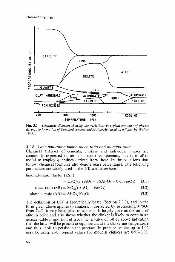
Cement chemistry
800 1200
TEMPERATURE (°C)COOLING
Fig. 3.1 Schematic diagram showing the variations in typical contents of phasesduring the formation of Portland cement clinker, loosely based on a figure by Wolter(W9).
3.1.2 Lime saturation factor, silica ratio and alumina ratioChemical analyses of cements, clinkers and individual phases arecommonly expressed in terms of oxide components, but it is oftenuseful to employ quantities derived from these. In the equations thatfollow, chemical formulae also denote mass percentages. The followingparameters are widely used in the UK and elsewhere.
lime saturation factor (LSF)
= CaO/(2-8SiO2 + 1 -2A12O3 + 0-65Fe2O3) (3.1)
silica ratio (SR) = SiO2/(Al2O3 + Fe2O3) (3.2)
alumina ratio (AR) = Al2O3/Fe2O3 (3.3)
The definition of LSF is theoretically based (Section 2.3.3), and in theform given above applies to clinkers; if corrected by subtracting 0-7SO3
from CaO, it may be applied to cements. It largely governs the ratio ofalite to belite and also shows whether the clinker is likely to contain anunacceptable proportion of free lime, a value of 1 0 or above indicatingthat the latter will be present at equilibrium at the clinkering temperatureand thus liable to persist in the product. In practice, values up to 1-02may be acceptable; typical values for modern clinkers are 0-92-0-98.
56

The chemistry of Portland cement manufacture
Other parameters similar in function to LSF are used in some countries.A suggested modification to the LSF definition, intended to allow for Mgsubstitution in alite, replaces CaO by (CaO + 0-75MgO) for MgO < 2%,or by (CaO +1-5) for M g O > 2 % (S24). In the German literature,Kalkstandard II corresponds approximately to LSF and KalkstandardIII to this modification of it.
The SR and AR, also respectively called silica modulus and aluminamodulus, are empirically based. For normal types of Portland cementclinker, SR is usually 2-0-3-0, and AR 1-0-4.0, but these ranges do notapply to special types, such as sulfate-resisting or white cement clinkers.The SR governs the proportion of silicate phases in the clinker. Increasein SR lowers the proportion of liquid at any given temperature in thekiln, and thus makes the clinker more difficult to burn. The AR governsthe ratio of aluminate to ferrite phases in the clinker, which hasimportant effects on cement properties, and also determines the quantityof liquid formed at relatively low temperatures. At 1338°C, for a giventotal content of A12O3 and Fe2O3, the quantity of liquid passes through amaximum at an AR of 1-38.
The proportions of raw materials are commonly calculated on the basisof the above parameters, most obviously by setting up and solvingsimultaneous equations; to fix n parameters, (w + 1) raw materials ofappropriate composition are required. It is also necessary to consider thedesired or allowable contents of minor components.
3.7.3 The Bogue calculationIn another approach, the quantitative phase composition is estimatedusing a procedure due to Bogue (B25). The calculation, in the formcommonly used in Europe, is as follows.
(1) Assume that the compositions of the four major phases are C3S,C2S, C3A and C4AF.
(2) Assume that the Fe2O3 occurs as C4AF(3) Assume that the remaining A12O3 occurs as C3A.(4) Deduct from the CaO content the amounts attributable to
C4AF, C3A and free lime, and solve two simultaneous equationsto obtain the contents of C3S and C2S.
This leads to the following equations, in which CaO is assumed to havebeen corrected for free lime:
C3S = 4-0710CaO - 7-6024SiO2 - 6-7187Al2O3 - l-4297Fe2O3 (3.4)
C2S= -30710CaO + 8-6024SiO2 + 5-0683Al2O3 + 10785Fe2O3
- 2-8675SiO2 - 0-7544QS (3.5)
C3A = 26504Al2O3 - 1 -6920Fe2O3 (3.6)
C4AF = 3-0432Fe2O3 (3.7)
As with LSF, the approach is applicable to cements if CaO is furthercorrected by deducting 0-7SO3. Because minor oxide components are
57

Cement chemistry
ignored, the total for the four main phases plus free lime will not add upto 100%. It is implicit in the approach that all the MgO is assumed tooccur as periclase. The phase composition calculated by Bogue's methodis related to the LSF in that a ratio of C2S to C3A < 0-546, calculatedwithout correcting the CaO content for free lime, corresponds to anLSF>10(D3).
In a variant of the Bogue calculation used in US specifications (ASTMC-150), free lime is not deducted and A12O3 is replaced by A12O3 +P2O5 -h TiO2. This latter modification typically raises the calculated C3Acontent by some 1-1%.
The results of the Bogue calculation are often called potential phasecompositions, because when the the procedure was devised, it wasgenerally considered that the principal source of error was failure toreach equilibrium during cooling. The results do indeed differ, oftenmarkedly, from the true phase compositions, notably in underestimatingalite and overestimating belite (Section 4.5.4), and it is unlikely thatequilibrium is maintained during cooling, but the principal direct sourceof error is that the compositions of the clinker phases differ considerablyfrom those of the pure compounds. In addition to their use in somespecifications, Bogue compositions are used for proportioning by settingup and solving equations to calculate the relative amounts of rawmaterials needed to obtain given 'potential' contents of C3S or otherphases. They have often been misused for other purposes on theassumption that they are close to the actual phase compositions. Spohnet al. (S24) have indicated the dangers of such uncritical use.
3.1.4 Enthalpy changes in clinker formationThe enthalpy change on formation of Portland cement clinker cannot becalculated with high precision, mainly because of uncertainties associatedwith the clay minerals in the raw material. Table 3.1 gives data for themain thermochemical components of the reaction, almost all of whichhave been calculated from a self-consistent set of standard enthalpies offormation, and which are therefore likely to be more reliable than othervalues in the literature. The conversion of the clay minerals into oxides isan imaginary reaction, but valid as a component in a Hess's lawcalculation. Few reliable thermochemical data exist for clay minerals;those for pyrophyllite and kaolinite can probably be used with sufficientaccuracy, on a mass basis, for other 2:1 and 1:1 clay minerals, respect-ively. The data for the pure compounds may similarly be used for theclinker phases. Table 3.2 illustrates the use of these data. The quantitativephase composition of the clinker was estimated from the bulk compositionby the method described in Section 4.4. The overall enthalpy change isoften calculated approximately from the bulk composition using a form-ula (Z7), and an experimental method for its determination has beendescribed (C8).
The overall enthalpy change in forming clinker is dominated by thestrongly endothermic decomposition of calcite. The component reactions
58

+ 1782+224
+538
+254-734-495-27
-157-105
CaCO3AS4H
AS2H2
FeO-CC2SC3SC3AC6A2FC4AF
The chemistry of Portland cement manufacture
Table 3.1 Standard enthalpies of reaction
Reaction AH (kJ) For 1 kg of
CaCO3 (calcite) -> CaO + CO2 (g)AS4H (pyrophyllite) ->
a-Al2O3 + 4SiO2 (quartz) + H2O (g)AS2H2 (kaolinite) - •
a-Al2O3 + 2SiO2 (quartz) + 2H2O (g)2FeO • OH (goethite) -> a-Fe2O3 + H2O (g)2CaO + SiO2 (quartz) -> /3-C2S3CaO + SiO2 (quartz) -> C3S3CaO + a-Al2O3 -+ C3A6CaO + 2a-Al2O3 + a-Fe2O3 -> C6A2F4CaO + a-Al2O3 + a-Fe2O3 -> C4AF
Values for starting materials and products at 25°C and 0101 MPa, calculated from the dataof Wagman et al. (W10), excepting those for the formation of C6A2F (N12) and C4AF (T8).The value for C4AF is for 20°C.
for the replacement of clay minerals by oxides are endothermic, becausethe heat required for dehydroxylation exceeds that liberated on formingthe products.
The formation of /?-C2S from lime and quartz is moderately exothermic,but that of C3S from lime and /3-C2S is endothermic, with AH =+59 kJ kg"1. All these calculations refer to reactants and products at 25°Cand 0-1 MPa. The enthalpy changes at the temperatures at which thereactions occur are somewhat different, because the specific heats ofreactants and products are not the same. The reaction of lime with C2Sgiving C3S changes from endothermic to exothermic at 1430°C (J4). Forthe decomposition of calcite at 890°C, AH is +1644 kJ kg"1 (L6).
Table 3.2 Enthalpy of formation of 1 kg of a Portland cement clinker
Component of reaction AH (kJ)
CaCO3 -> CaO + CO2 (g) +2138AS4H (pyrophyllite) - • a-Al2O3 + 4SiO2 (quartz) + H2O (g) +34AS2H2 (kaolinite) -> a-Al2O3 + 2SiO2 (quartz) + 2H2O (g) +212FeO • OH (goethite) -» a-Fe2O3 + H2O (g) +83CaO + SiO2 (quartz) - • C3S -3332CaO + SiO2 (quartz) -> /?-C2S -983CaO +a-Al2O3 -> C3A - 36CaO + 2a-A12O3 + a-Fe2O3 -> C6A2F -10Total +1757
The contributions to AH are calculated assuming the starting materials to be: calcite,1-20kg; quartz, 010kg; pyrophyllite, 015kg; kaolinite, 004kg; goethite, 003kg. Theproducts are assumed to be: C3S, 0-673 kg; /3-C2S, 0-133 kg; C3A, 0118 kg; C6A2F, 0-064 kg;free CaO, 0010kg; total, 100kg.
59

Cement chemistry
3.2 Raw materials and manufacturing processes3.2.1 Raw materials and fuelThese, and manufacturing processes, will be considered only to the extentneeded for a basic understanding of their chemistry; fuller accounts aregiven elsewhere (D4,G25,K8,P13).
The raw mix for making Portland cement clinker is generally obtainedby blending a calcareous material, typically limestone, with a smalleramount of an argillaceous one, typically clay or shale. It may be neces-sary to include minor proportions of one or more corrective constituents,such as iron ore, bauxite or sand, to correct the bulk composition. On theother hand, some argillaceous limestones and marls have compositionsnear to that required, making it possible to use a blend of closely similarstrata from the same quarry.
Limestones vary in physical characteristics from compact rocks of lowporosity to friable and highly porous ones, such as chalk, which maycontain up to 25% of water. All consist essentially of calcium carbonate,normally in the polymorphic form of calcite. Other naturally occurringforms of CaCO3, such as shell deposits, are sometimes used. Manylimestones contain significant amounts of minor components, either assubstituents in the calcite or in accessory phases, some of which aredeleterious if present in amounts exceeding a few per cent (e.g. MgO,SrO), a few tenths of a per cent (e.g. P2O5, CaF2, alkalis) or even less(some heavy metals).
Suitable shales and clays typically have bulk compositions in the regionof 55-60% SiO2, 15-25% A12O3 and 5-10%Fe2O3, with smaller amountsof MgO, alkalis, H2O and other components. Mineralogically, their mainconstituents are clay minerals, finely divided quartz and, sometimes, ironoxides. The dominant clay minerals are usually of the illite and kaolinitefamilies, but small amounts of smectites (montmorillonite-type minerals)may also be present. Kaolinite has a 1:1 layer silicate structure and ionicconstitution Al2(Si2O5)(OH)4. Illites and smectites have 2:1 layer silicatestructures, derived from those of pyrophyllite [Al2(Si2O5)2(OH)2] or talc[Mg3(Si2O5)2(OH)2] by various ionic substitutions and incorporation ofinterlayer cations and, in smectites, water molecules. In place of clays orshales, other types of siliceous rocks, such as schists or volcanic rocks ofsuitable compositions, are sometimes used.
Pulverized coal, oil, natural gas and lignite have all been widely used asfuels, but due to pressing environmental and economic requirements areincreasingly being supplemented by waste materials. In 1995, Bannon(B26) reported that fuel usage in Europe was coal, 38%; petroleum coke,36%; lignite, 8%; fuel-oil, 7%; natural gas, 2%; and various alternativefuels, 9%. Worn-out or reject tyres and many kinds of industrial andmunicipal wastes are often used. In addition to conserving non-renewablefossil fuels and in some cases lowering CO2 emissions, the use of wastematerials as fuels can provide a means of safe and environmentallyacceptable disposal. Some waste materials can be used in the raw feed;energy can be saved and CO2 emission decreased if even a part of theCaO can be provided by a material, such as blastfurnace slag, that does
60

The chemistry of Portland cement manufacture
not require decarbonation. Some materials, such as flyash (pulverizedfuel ash, pfa) can serve as raw materials that also possess some fuelcontent. The contribution of the fuel to the clinker composition must betaken into account, especially with coal or lignite, which producesignificant quantities of ash broadly similar in composition to theargillaceous component. Some fuels also contribute sulfur.
3.2.2 Dry and wet processes; energy requirementsComminution and mixing of the raw materials may be carried out eitherdry or wet. The theoretical amount of heat needed to produce 1 kg ofclinker from typical raw materials is about 1750 kJ (Section 3.1.4).Additional heat is required because heat is retained in the clinker, kilndust and exit gases after they leave the system, lost from the plant byradiation or convection, and, in the wet process, used to evaporate water.Table 3.3 compares the heat requirements of the wet process and amodern version of the dry process, in each case assuming typical rawmaterials and proper plant design and operating conditions. The greaterthermal efficiency of the dry process occurs largely because there is noadded water to be evaporated. The total energy requirement of a cementworks includes also electrical energy used in operating the plant, to whichgrinding of raw material and of clinker make important contributions.This is higher for the dry process than for the wet process, typical valuesbeing 120kWh and 77kWh per tonne of cement (432kJkg-1 and277kJkg-1 respectively), including that used for grinding the clinker ineach case (D5), but the difference is small compared with that in theamounts of fuel required.
The wet process has certain advantages if the raw materials are alreadysoft and moist, but its low fuel efficiency has rendered it obsolescent, andthe following description is of a modern version of the dry process.
3.2.3 The dry process; suspension preheaters and precalcinersThe raw materials first pass through a series of crushing, stockpiling, mill-ing and blending stages, which yield an intimately mixed and dry raw meal,of which typically 85% passes through a 90/zm sieve. With automated,
Table 3.3 Heat requirement in dry and wet process kilns (kJ/kg of clinker)
Dry Wet
Theoretical heat requirement for chemical reactionsEvaporation of waterHeat lost in exit gases and dustHeat lost in clinkerHeat lost in air from coolerHeat lost by radiation and convectionTotal 3306 5699
Dry kiln with suspension preheater. Data adapted from Ziegler (Z8).
61
18071362388427348
1741236475359100682

Cement chemistry
computer-controlled procedures, the LSF, SR and AR can be maintainedconstant to standard deviations of 1%, 0-1 and 0 1 , respectively.
The raw meal passes through a preheater and frequently also a pre-calciner before entering a rotary kiln. A preheater is a heat exchanger,usually of a type called a suspension preheater in which the movingpowder is dispersed in a stream of hot gas coming from the kiln. Figure 3.2shows a common arrangement, which employs a series of cyclones. Heattransfer takes place mainly in co-current; the raw material passes throughthe preheater in less than a minute, and leaves it at a temperature of about800°C. These conditions are such that about 40% of the calcite is
EXIT GAS
KILNGASES
KILNFEED
Fig. 3.2 Schematic diagram of a four-stage cyclone-type suspension preheater.P indicates the position at which a precalciner burner may be incorporated.
62

The chemistry of Portland cement manufacture
decarbonated. It is possible to introduce a proportion of the fuel intoa preheater, with a corresponding reduction in the quantity fed to thekiln; a precalciner is a furnace chamber introduced into the preheater intowhich 50-65% of the total amount of fuel is introduced, often with hotair ducted from the cooler. The fuel in a precalciner is burned at arelatively low temperature; heat transfer to the raw meal, which is almostentirely convective, is very efficient. The material has a residence time inthe hottest zone of a few seconds and its exit temperature is about 900°C;90-95% of the calcite is decomposed. Ash from the fuel burned in theprecalciner is effectively incorporated into the mix.
Because less heat is supplied to the kiln, precalcination allows the rateat which material can be passed through a kiln of given size to be greatlyincreased, thus saving on capital cost. Alternatively, the rate of providingheat can be reduced, which lengthens the life of the refractory lining. LessNOX is formed, since much of the fuel is burnt at a low temperature, andwith some designs NOX formed in the kiln may be reduced to nitrogen.Low-grade fuels can often be used in the precalciner. Precalcination mayalso make it economically feasible to deal with the problem, discussed inSection 3.2.5, of formation of deposits in the duct carrying the hot gasesfrom the kiln to the preheater.
3.2.4 The rotary kilnThe rotary kiln is a tube, sloping at 3-4% from the horizontal androtating at l-4rev/min, into which the material enters at the upper endand then slides, rolls or flows counter to the hot gases produced by aflame at the lower or 'front' end. In a system employing a precalciner, thekiln is typically 50-100 m long and its ratio of length to diameter is 10-15.The maximum material temperature, of about 1450°C, is reached near thefront end of the kiln in the 'burning zone', also called the clinkering orsintering zone, in which the material spends 10-15 minutes. The kiln islined with refractory bricks, of types that vary along its length in accord-ance with the varying gas and material temperatures. The bricks becomecoated with a layer of clinker, which plays an essential part in theinsulation and in extending their life.
Nodules of clinker, typically 3-20 mm in diameter, are formed in asemi-solid state in the burning zone, and solidify completely on cooling,which begins in a short cooling zone within the kiln, and continues in acooler. In modern plants, when the nodules leave the kiln, their internaltemperatures are around 1350°C, but their surface temperatures areconsiderably lower.
Liquid or pulverized solid fuels are blown into the kiln through anozzle with 'primary' air. Additional, 'secondary' air is drawn into thekiln through the clinker cooler. The flame in the rotary kiln must meetseveral requirements. The clinker must be correctly burned, so as tominimize its content of free lime, with the least expenditure of fuel. Theash from a solid fuel must be uniformly absorbed by the clinker. Fornormal Portland cements, the conditions must be sufficiently oxidizingthat the iron is present in the cooled clinker almost entirely as Fe3+;
63

Cement chemistry
however, for white cements, mildly reducing conditions may be prefer-able. Proper flame control also extends the life of the refractory lining ofthe kiln. Computer-aided or fully automated control of kiln operatingconditions is increasingly used.
3.2.5 Circulation of volatiles; dust; cooling of clinkerIn the hotter parts of the kiln, the K, Na, S, C\ and some other elementsprovided by the raw material or fuel are partly or wholly volatilized. Thefractions that are not pass into the clinker. The volatilized material isswept back with the hot gases to the cooler parts of the system, where,assuming that a suspension preheater or precalciner is used, it is largelyreabsorbed, so that cycles are set up. Material that is not reabsorbed mayleave the system through the preheater as gas or dust, but some can formsolid or semi-solid deposits. Deposits formed in this and other ways canseriously restrict the movement of material and gases; in the kiln, theyform rings. They can form in the duct carrying the hot gases from the kilnto the preheater. With some raw materials or fuels, it is necessary todivert part of the gas through a bypass and to filter out the dust that itcarries, and to accept the consequent losses of heat and material, butchanges in the raw materials or fuel may sometimes be a preferablesolution (D6).
Dust from the kiln is largely captured in a suspension preheater; thatwhich is not is removed by an electrostatic precipitator before the gaspasses up the chimney. The flow of gas is aided by an exhaust fan. The dustis as far as possible returned to the system by mixing with the raw meal orwith the fuel (insufflation), though the extent to which either is possiblemay be restricted by its content of alkali sulfates or chlorides, which if highcould lead to an unduly high recirculating load, conducive to the for-mation of deposits or undesirably high concentrations in the clinker.
The clinker cooler is essentially a heat exchanger that extracts heatfrom the clinker for return to the system; also, a cooled clinker is morereadily transported, ground or stored. Rapid cooling from the clinkeringtemperature down to 1100°C produces a better quality clinker (Section3.5.5), and the clinker should be effectively air-quenched as soon as itleaves the burning zone. When the clinker enters the grinding mill, itstemperature should preferably be below 1100°C. Current practice favoursgrate coolers, in which the clinker passes over moving grates throughwhich air is blown. More air is needed for cooling than for combustion inthe kiln, especially with a fuel-efficient process. Some of the excess('tertiary air') may be ducted to a precalciner or used to dry the coal andraw materials, but a quantity normally remains for which it has proveddifficult to find economically viable uses, and which is therefore cleanedand exhausted; steam raising for electicity generation has been suggestedas a possible use.
3.2.6 Other processes for clinker production; clinker grindingIn the wet process, the raw material is fed as a slurry directly to a rotarykiln, which typically has a length to diameter ratio of about 30 and may
64

The chemistry of Portland cement manufacture
be up to some 200 m long. In surviving wet process kilns, the slurrytypically has a water content of 30-35%. A system of chains near theback end assists heat transfer. Cycling of volatiles and of dust is much lesspronounced than with preheater systems. In the semi-wet process, someimprovement in fuel efficiency is obtained by pressing out part of thewater to produce a cake containing somewhat below 20% of water, whichcan be fed to the kiln directly or through certain types of preheater. In thesemi-dry or Lepol process, the raw materials are made into nodules withjust over 10% water content, which are fed to a moving grate preheater.The fuel efficiency is lower than that obtainable with a suspensionpreheater. Combined processes have been brought into operation invarious countries for making cement and other materials, such as alumin-ium, iron or sulfuric acid (G26). While there are problems associated withsuch processes, the latter may become increasingly important as classicalraw materials become scarcer and environmentally acceptable ways ofdisposing of industrial wastes more difficult.
To produce Portland cement, the clinker is ground together withgypsum. Portland cement clinker has a long storage life, and while it maybe ground immediately, there are often good reasons for grinding itintermittently, and not necessarily in the same plant. Compositionaland other variations in the clinker can be much reduced by using stor-age systems in which blending occurs. Natural gypsum, which is gener-ally used, commonly contains significant proportions of such impur-ities as anhydrite, quartz, calcite and clay minerals. In some countries,by-product gypsums from various industrial processes are used.A proportion of anhydrite may also be added. Some national specifi-cations permit the addition of materials other than calcium sulfate. Tomake interground composite cements, widely varying proportions ofgranulated blastfurnace slag, flyash or other materials are added(Chapter 9). Grinding typically requires a power consumption of35-50kWh tonne"1 (125-180kJkg"1), almost all of which is convertedinto heat, and cooling is required.
3.3 Reactions below about 1300 C3.3.1 Decomposition of carbonate mineralsThe dissociation pressure of calcite reaches 0101 kPa (1 atm) at 894°C(S25) and the decarbonation reaction is highly endothermic (Section3.1.4). The rate of decarbonation becomes significant at 500-600°C if asufficiently low partial pressure of CO2 is maintained or if the calcite isintimately mixed with materials, such as quartz or clay mineraldecomposition products, that react with the calcium oxide. Even in aprecalciner such mixing occurs, aided by agglomeration caused by thepresence of low-temperature sulfate melts.
In the absence of other substances, dolomite [CaMg(CO3)2] begins todecompose rapidly in air at about 750°C, giving initially periclase and acarbonate of higher Ca/Mg ratio. The decomposition temperature ismuch affected by the presence of other substances.
65

Cement chemistry
The mechanism and kinetics of calcite decomposition have been muchstudied. The reaction proceeds by the movement inwards from thesurface of an interface, behind which the material is converted into lime,thus producing a highly porous pseudomorph. The interface moves at aconstant rate, implying that the rate at any instant is proportional to thearea of the interface. In principle, the rate is controlled by the slowest ofthe following five steps:
(1) transfer of heat to the exterior surface(2) transfer of heat from the exterior surface to the interface(3) chemical reaction at the interface(4) transfer of carbon dioxide to the exterior surface(5) transfer of carbon dioxide away from the exterior surface.
Hills (H21) showed that, contrary to some earlier opinions, it was notpossible to determine which is the rate-controlling step either from theobserved relationship between the extent of reaction and the time or fromthe apparent energy of activation, obtained by applying the Arrheniusequation to the rate constant determined at different temperatures. Forlarge particles and low CO2 pressures, the temperature within the spherecould be as much as 45 K below that of the surrounding gas, indicatingthat heat transfer controlled the rate. For the conditions existing in a rotarykiln, in which decomposition occurs in a deep, moving mass of mat-erial, heat transfer again determines the rate (B27). A rotary kiln is wellsuited to the later stages of clinker production, but much less so for calcina-tion, which if carried out in it requires some tens of minutes for completion.
Very different conditions exist in a precalciner, where the raw meal isdispersed in hot gas. The reaction still proceeds by the movement of aninterface inwards, but the rate is controlled by the chemical reaction andthe temperature within the particle is virtually that of the surrounding gas(B28,V2). The rate is much higher than in a rotary kiln, and, as seenin Section 3.2.3, decomposition is normally 90-95% complete within afew seconds.
3.3.2 Decomposition of clay minerals and formation of productsLaboratory experiments in which single substances or mixtures areheated in stationary containers in air provide a starting point forunderstanding the reactions that occur in manufacturing clinker, thoughcaution is needed in applying the results because of the importantdifferences in conditions.
The behaviour of clay minerals on heating depends on their structure,composition, crystal size and degree of crystallinity. In general, anyinterlayer or adsorbed water is lost at 100-250°C; dehydroxylation beginsat 300-400°C and is rapid by 500-600°C. Clay minerals in which Al3+ isthe predominant octahedral cation do not form phases of radicallydifferent structure as the immediate products of dehydroxylation, butundergo varying degrees of structural modification and disorganizationdue to the replacement of 2OH~ by O2~. Kaolinite gives a poorly crystal-line product, called metakaolin; with illites, the structural disorganization
66

The chemistry of Portland cement manufacture
is less marked, perhaps because less water has to be lost. Above about900°C, all begin to give new, crystalline phases, which are typically Al-Sispinel, cristobalite and, above 1100°C, mullite.
Quartz undergoes a minor, rapid and reversible phase transition toa-quartz at 573°C. It is unstable relative to tridymite at 867-1470°C, andto cristobalite above 1470°C. These changes are slow in the absence ofother materials, but many admixed materials accelerate them, and lead toformation not of tridymite, but of cristobalite at temperatures over about1000°C.
As noted in Section 3.3.1, the decarbonation of calcite is greatlyfavoured by intimate mixing with quartz or clay minerals. Under theseconditions, much CO2 is lost before any free lime can be detected. Theformation of C2S as an early product is well established, but the situationwith the calcium aluminate phases is more complex, no one phase beingdominant as an initial product (Wll). The aluminate or aluminosilicatephases most often reported as early or intermediate products in labora-tory experiments with pure chemicals or raw meals have been CA, Ci2A7and, less frequently, gehlenite (C9,C10,D7-D9,I9,L8,L9,Rll,W12,W13).C3A can form by 850°C (C10,L9) but seems usually to be a later product.Ferrite phase forms readily, and is initially of low Al/Fe ratio (D8,R11).
The reactions are notably accelerated by water vapour (CIO). In thecement kiln or precalciner agglomeration may influence their course.Glasser (G27,G28) reviewed kinetic studies. The complexity of themechanisms has not always been recognized, and it is doubtful whetherkinetic data suffice to determine them, but electron microscopy and X-raymicroanalysis are beginning to provide reliable information (R12).
3.3.3 Sampling from cement kilns or preheater outletsSeveral investigators have examined samples from rotary kilns duringnormal operation. In one such study, Weber (W13) obtained samples, andmeasured temperatures, mainly using sampling ports in the kiln walls. Inall cases, the raw materials were limestone and marl, and the fuel waspulverized coal. CA and Ci2A7, but not gehlenite, were found as earlyproducts. As in the laboratory studies, much calcite decomposed before anyfree lime was detected. The free lime content passed through a maximumvalue of up to 17%, referred to the mass of clinker, about 15 m from thefront end of the kiln. At this point, the measured temperature was about1000°C. Laboratory studies (19) and analyses of kiln input meals fromprecalciners, described below, show that the maximum content of free limereached varies greatly with the nature of the raw material.
One may also examine samples from kilns that have been shut down,though uncertainties inevitably exist due to possible phase changes andmovement of material during cooling, which is carried out with the kilnstill rotating. Moore (M35) reported an XRD study of charge andcoating samples taken from numerous points along the lengths of severalkilns. Sulfate phases were prominent in both types of sample taken fromthe cooler parts of the kiln, and comprised anhydrite, C4A3S, C5S2S,calcium langbeinite and hydroxyl-ellestadite (Ci0S3S3H). KC1 was
67
Cement chemistry
sometimes found. Spurrite (C5S2C), /3-C2S, Ci2A7 and ferrite wereusually also found before all the calcite had decomposed. Gehlenite wasusually found in coating samples at intermediate temperatures, but rarelyin the charge; CA was never found. C3A was a late product. Rarely,ferrite was found as a late product, being replaced earlier by iron-con-taining spinel, presumably indicating the existence of reducing conditionsat the cooler end of the kiln. Moore concluded that sulfates and chlorideswere important mineralizers and that both spurrite and C4A3S playedparts in the normal reaction sequence. Later results probably do notexclude this latter conclusion, but both phases can undoubtedly beundesirable artefacts.
Wolter (W14) determined the phase compositions of kiln inlet mealsfrom about 20 plants using cyclone preheaters, usually with precalciners.XRD showed that the decomposition products of the clay minerals wereespecially reactive, though some reaction of quartz also occurred. Phasesdetected, and some notable absences, were as follows.
(1) Unreacted phases from the raw meal: calcite, quartz, minor micaand felspars, traces of clay minerals.
(2) Product phases: free lime, periclase, poorly crystalline belite(/?-C2S), ferrite, Ci2A7 assuming that enough A12O3 was present,and often spurrite. Gehlenite was possibly present but, if so, wasminor compared with belite. Less basic silicates and aluminates(e.g. CA, CA2) were absent.
(3) Condensed volatiles: arcanite (K2SO4), sylvine (KC1), aphthita-lite (rare), NaCl (exceptionally), anhydrite (for high SO3/alkaliratios, and then less than expected). Absences includedthenardite, calcium langbeinite, alkali carbonates, C4A3S andC5S2S.
(4) Clinker dust and coal ash: alite, flyash (rare).(5) Secondary products formed on storage or treatment: calcium
hydroxide, hemihydrate.
The quantitative composition varied widely, depending on the degree ofcalcination, heterogeneity of the raw meal, and whether kiln dust or vola-tiles were recirculated. Ci2A7 and ferrite formed easily. At high degrees ofcalcination, virtually all the A12O3 and Fe2O3 had reacted, 10-60% of thetotal SiO2 content was present as belite or spurrite and the content of freelime was 5-40%. The proportion of the CaO released from the calcitethat was combined in other phases was high at low degrees of calcina-tion, and decreased as the latter proceeded; at 40-70% calcination, it was30-75%, or in rare cases over 90%.
3.3.4 Reaction mechanismsThe mechanisms of the reactions in cement raw meals (C9,C 11,19) andlime-silica composites (W15) have been studied using light and electronmicroscopy, XRD, high-temperature XRD and high-temperature lightmicroscopy, EPMA and thermal analysis, and free lime determinations.Below about 1200°C reactions occur largely in the solid state, the first

The chemistry of Portland cement manufacture
visible effect in cement raw meals being the appearance of reaction rimsaround the larger quartz grains, which later become replaced by clustersof belite crystals. Chromy (C9) found that the rims comprised zones ofcristobalite, isotropic material of refractive index 1-515—1-525 and(furthest out) belite. By 1200°C, the belite layer was up to 2-3/imthick, and the isotropic material, which formed a thicker layer, wastending to break through, to form necks linking adjacent quartz grains.The isotropic material contained Ca and Si, and had Ca/Si < 1-0; it gave adiffuse XRD peak at 0-37 nm and was probably a glass. XRD and opticalevidence also showed the presence of wollastonite and a little tridymite; insamples cooled from 1280°C, both were detectable optically, as needlesdispersed in the amorphous material and as crystals on the border of thelatter with the quartz, respectively. The wollastonite had presumablyformed from a-CS on cooling.
At 1200-1300°C, high-temperature light microscopy showed move-ment of the silica cores and CS crystals; the amorphous material wassoftening. Where the belite shell had burst, clusters of belite crystals witha central pore usually replaced the original quartz grain, but where it hadnot, these clusters only formed at a higher temperature and were morecompact, with very little interstitial material.
Maki et al. (M36) studied the formation of belite clusters at 1400°C.Layers of belite and liquid formed within the quartz grains and grew outfrom them, so that the products of neighbouring grains coalesced. Threekinds of belite crystal, differing in origin, texture and composition, weredistinguished in the clusters.
Rapid increase in temperature is desirable at temperatures below thoseat which substantial liquid formation occurs (B29,C9,C11,G28,S26,W9).Most of the belite, and almost all of the other product phases,subsequently either melt or react in the presence of the melt, and thereis no merit in promoting crystal growth or removal of imperfections,which would impede these processes. Slow heating may also allow thedecomposition products of the clay minerals to transform into lessreactive phases. It can also lead to the formation of microstructuresunfavourable to the later reactions; Chromy (C9) found that it allowedthe belite shells around the silica particles to thicken, producingcomposites slow to react with lime. In contrast, rapid heating increasesmovement of the liquid phase, when this forms, and thus improves themixing of the calcareous and siliceous constituents (Cll).
3.3.5 Condensation or reaction of volatilesBucchi (B30) reviewed the cycling of volatiles in kilns and preheaters.Condensation or reaction of species from the gas stream takes placebelow about 1300°C. The sulfate and chloride phases produced werenoted in Section 3.3.3. Some of the material thus deposited is liquid, evenat quite low temperatures: melting in the Na2SO4-K2SO4-CaSO4-KClsystem begins below 700°C (RIO). These low-temperature melts haveboth good and bad effects. Deposition on the feed can promote reactions,as noted earlier. Deposition in the preheater or kiln can cause serious
69

Cement chemistry
obstructions, and condensation of volatiles is responsible for theformation of kiln rings and deposits in preheaters at temperaturesbelow 1300°C (A5,B30,C12,S27,S28). Dust particles become coated withfilms of liquid condensate which cause them to adhere to obstacles orcooler surfaces. The temperature within a coating or deposit graduallyfalls as more material is deposited; this allows the formation ofcompounds within the body of the coating that differ from those presenton the hot face.
Spurrite, if formed, reinforces deposits by producing a mass of inter-locking crystals; C4A3S and C5S2S behave similarly. The kiln atmosphere ishigh in CO2, and spurrite is readily formed on heating either clinker (A5) orraw meal (S27) in CO2 at 750-900°C. It decomposes by 950°C (A5). In SO2,either raw meal or clinker gives anhydrite at 550-1150°C, and silicosulfateat 1050-1150°C; in mixed gases, the reactions with SO2 are favoured overthose with CO2, and if K2O is present in the solid, calcium langbeinite isformed at 600-900°C (A5). Formation of spurrite appears to be favouredby presence of K2O or chlorides and inhibited by phosphates (S27), whichare, however, undesirable constituents of clinker. Fluoride also appears tofavour formation of spurrite and silicosulfate.
Fluorides and compounds of Zn, Cd, Tl and Pb also undergo cyclingand can be deposited in preheaters (K9). Emission of the toxic heavymetals must be avoided. Fluoride phases that have been reported indeposits include KCai2(SO4)2(SiO4)4O2F (F10) and an apatite phase ofcomposition K3Ca2(SO4)3F (T9,P14).
3.4 Reactions at 1300-1450 C3.4.1 Quantity of liquid formedThe processes described in this section occur in the presence ofsubstantial proportions of liquid. They comprise:
(1) melting of the ferrite and aluminate phases, and some of the belite(2) nodulization(3) reaction of the free lime, unreacted silica and some of the belite,
to give alite(4) polymorphic change of belite to the a form(5) recrystallization and crystal growth of alite and belite(6) evaporation of volatiles.
At the clinkering temperature, the principal phases present at equilibriumare alite, belite and liquid. For the pure CaO-C2S-C3A-C4AF system,this phase assemblage will, except at high Al2O3/Fe2O3 ratios, be reachedby 1400°C (Section 2.3.3). Following Lea and Parker (L5), the quantityof liquid formed in a mix of given composition at this temperature maybe calculated as follows.
(1) All the Fe2O3 is present in the liquid; hence the percentage ofliquid is 100 x Fe2O3/(Fe2O3)i, where Fe2O3 and (Fe2O3)i are thepercentages of that component in the mix and in the liquid,respectively.
70

The chemistry of Portland cement manufacture
(2) The composition of the liquid is governed only by the A12O3/Fe2O3 ratio of the mix, being represented by the point on theC3S-C2S surface where the 1400°C isotherm is intersected by aplane corresponding to the value of that ratio. The intersectionof the 1400°C isotherm with the C3S-C2S surface runs near andapproximately parallel to the boundaries between that surfaceand the C3A and C4AF surfaces. Table 3.4 gives liquid composi-tions for four values of the Al2O3/Fe2O3 ratio.
(3) The Al2O3/Fe2O3 ratios and Fe2O3 contents in these composi-tions are related by the empirical equation
Al2O3/Fe2O3 = -0-746 + 33-9/(Fe2O3)! (3.8)
which may be rearranged to give
Fe2O3/(Fe2O3)i - (A12O3 + 0-746Fe2O3)/339 (3.9)whence the percentage of liquid in the mix is 2-95Al2O3-h2-20Fe2O3.
(4) Lea and Parker (L5) corrected for the contributions to the liquidof MgO and alkalis. Assuming that the solubility of MgO in theliquid is 5-6%, and that the percentage of liquid is about 30%,the contribution from MgO was assumed to be the MgO contentof the mix or 2%, whichever was smaller. The liquid wasassumed to contain all the K2O and Na2O.
Similar calculations were made for other temperatures. At lowertemperatures, the relationship differs according to whether the A12O3/Fe2O3 ratio is above or below 1-38, the value for the C3S-C2S-C3A-C4AF invariant point. Formulae for the percentage of liquid for variouscombinations of temperature and Al2O3/Fe2O3 ratio are:
1450°C 300Al2O3 -f 2 25Fe2O3 + MgO* + K2O + Na2O
1400°C 2-95Al2O3 + 2-20Fe2O3 + MgO* + K2O + Na2O
1338°C (Al2O3/Fe2O3 > 1-38) 610Fe2O3 + MgO* + K2O + Na2O
1338°C (Al2O3/Fe2O3< 1-38) 8-20Al2O3
- 5 22Fe2O3 + MgO* + K2O + Na2O
Table 3.4 Compositions of liquids in equilibrium with C3S and C2S inthe CaO-Al2O3-Fe2O2-SiO2 system at 1400°C
Mass ratio Mass percentage
6062-620-940-64
CaO
56-656-455153-9
A12O3
30-326-218-815-3
Fe2O3
50100200240
SiO2
8-07-4616-8
From Lea and Parker (L5), with corrections supplied by F.M. Lea and notedby Bogue (B31).
71

Cement chemistry
Fig. 3.3 M«55 percentages of liquid at 1338° C (full lines) and 1400°C (brokenlines) in the CaO-Al2O3-Fe2O3-SiO2 system (B32).
where MgO* denotes an upper limit of 2-0% to the term for MgO.Typical percentages of liquid (for a mix with 5-5% A12O3, 3-5% Fe2O3,15% MgO and 10% K2O) are thus 24% at 1340°C, 26% at 1400°C and27% at 1450°C.
Such results, omitting the contributions of MgO and alkalis, areconveniently represented as contours on plots of A12O3 against Fe2O3
(Fig. 3.3). At 1400°C, the effects of the two oxides on the quantity ofliquid are additive and fairly similar mass for mass. At 1338°C the effectsare not additive, the maximum amount of liquid for a given total contentof A12O3 and Fe2O3 being obtained at an Al2O3/Fe2O3 ratio of 1-38.
The effects of the minor components on the quantity of liquid formedhave not been thoroughly studied. Swayze's results (S14) indicate that theMgO depresses liquidus temperatures by about 50 K and increases theAl2O3/Fe2O3 ratio in the liquid at the C3S-C2S-C3A-C4AF eutectic to1-63. Alkalis and sulfate may depress the liquidus temperatures further,but the effects of liquid immiscibility must be taken into consideration.
3.4.2 Burnabilities of raw mixesThe 'burnability' of a mix denotes the ease with which free lime can bereduced to an acceptable value in the kiln. For laboratory use, it hasusually been defined either by the quantity of free lime present after aspecified regime of heat treatment, or by the time of such treatmentneeded to reduce the free lime content to some specified value, though
72

The chemistry of Portland cement manufacture
some investigators have used dynamic heating or other regimes inattempts to simulate kiln conditions more closely. As Bucchi (B29) andSprung (S26) have noted, none of the measures so far proposed has morethan comparative significance, as they do not take into account suchfactors as the atmosphere, movement of material or rate of heat transferin the kiln. The rate at which the free lime reacts depends not only oncharacteristics of the raw mix, but also on the effects on the latter of theheat treatment received before entering the clinkering zone and theconditions existing in that zone itself. The measures can strictly bejustified only for a given kiln and set of operating conditions.
Many studies have shown that burnability decreases with increasingLSF or increasing SR. Increase in LSF implies more CaO that has toreact, and increase in SR implies less liquid at a given temperature. Theserelationships have been discussed quantitatively (C13). The AR isrelevant at low clinkering temperatures, because it then greatly affectsthe quantity of liquid (Section 3.4.1) and the temperature at whichsubstantial formation of liquid begins, but at 1400°C and above its effectis smaller; however, in the extreme case of white cements, the AR is veryhigh and burnability is low. The temperature at which melting begins isalso affected by the contents of minor components, such as MgO, and bythe addition of fluxes. Burnability is affected not only by the quantity ofliquid, but also by its physical properties, some of which are consideredin Section 3.6.
Burnability is affected by the particle size of the raw mix, and especiallyby the contents of coarse particles (C14,H22,L9). During calcination,large particles of calcite and of siliceous materials are converted intoaggregates of lime crystals and clusters of belite crystals respectively. Thesize distributions of these large particles determine the time requiredduring the last stages of clinkering, when the free lime content is falling toits final value. The fine end of any distribution likely to occur in practiceis less important. For assessing burnability at 1400°C, the proportions ofcalcite particles larger than 125/im, and of quartz particles larger than44 /xm, are particularly important (C14).
Burnability also depends on the nature, microstructures and intimacyof mixing of the raw materials and on the contents of minor components.Silica present as quartz is less reactive than that present in clay minerals,and a limestone high in silica or silicate minerals is likely to be morereactive than one that is nearly pure calcite. Inadequate mixing of theparticles of the different constituent rocks present in the raw mix haseffects broadly similar to those of too high a proportion of coarseparticles. Petersen and Johansen (PI5) discussed the mixing of particlesfrom a statistical viewpoint.
Several workers have obtained expressions relating burnability tocompositional and other parameters (C13-C15,F11,L9). Fundal (Fl l ) ,defining burnability (Ci4Oo) by the percentage of free lime remaining after30min at 1400°C, found that
5-1SR-107) +0-93544+ 0-56Ci25 + 0-2^q (3.10)
73

Cement chemistry
where SR denotes silica ratio, S44 and C125 are the percentages ofsiliceous particles above 44 fim and of calcareous particles above 125/xmrespectively, and Aq is the percentage of acid-insoluble material, assumedto be quartz. This relation was considered to hold for LSF values of88-100% and silica ratios of 2-6.
3.4.3 NodulizationNodule formation occurs through the sticking together of solid particlesby liquid. Petersen (P16,P17) showed that the nodules grow partly bycoalescence and partly by accretion, and developed a theory to predictthe size distribution. Timashev (Tl) regarded the process as one in whichan initially relatively open assemblage of solid particles was compactedthrough the action of the liquid, initially by rearrangement of particles,and increasingly later by dissolution and crystallization processes.Nodulization requires an adequate proportion of liquid, and is favouredby low viscosity and high surface tension of the liquid and by smallparticle size of the solid (T1,P17). If there is not enough liquid, the outerparts of the nodules become enriched in silicates, some of which formdust (PI 5). Overburning can have a similar effect (L10). If the friable skinof large alite crystals remains on leaving the kiln, the clinker has asparkling appearance. Much is abraded in the kiln, to form a dust thatcan cause rings or other deposits to form. It can also reaggregate to formporous, alite-rich lumps, which can incorporate small clinker nodules.
Nodulization, chemical reactions and evaporation of volatiles areinterdependent. Alite formation and loss of volatiles affect nodulization,and the compaction that the latter entails must affect the kinetics of theformer processes. Alite formation thus occurs in a changing environment.Initially, the clinker liquid is not a continuous and uniform mediumenveloping the grains of lime, belite and other solid phases; rather, it fillsseparate pores and capillaries, forming thin films on the particles, andthere are large local variations in composition (Tl). As compactionproceeds, it becomes more continuous and more uniform.
3.4.4 Formation and recrystallization of aliteIn the study described in Section 3.3.4, Chromy (C9) showed that a meltof low Ca/Si ratio began to form at 1200-1300°C around the originalquartz grains, which were being converted into clusters of belite crystals.From 1300°C, a liquid also began to form around the grains of lime. Itdiffered in reflectance from that surrounding the silica or belite crystalsand was considered to be of higher Ca/Si ratio. Where it bordered on thebelite clusters, alite was precipitated, initially as a compact layer. Thislater recrystallized, allowing the liquids to mix. Alite now formed morerapidly; the belite clusters contracted, and the crystals that remainedrecrystallized.
In further studies, Chromy and co-workers (C11,C15,C16) distin-guished three stages in the reaction at clinkering temperatures. In thefirst, melt and belite are formed. In the second, belite continues to form;this stage yields a material consisting of isolated clusters of lime crystals
74

The chemistry of Portland cement manufacture
having thin layers of alite on their surfaces and dispersed in a matrix ofbelite crystals and liquid. In the third, the clusters of lime react with thesurrounding belite to give alite, by a mechanism based on diffusion ofCaO through the liquid. The temperature increases rapidly during thefirst stage, but the subsequent stages are isothermal.
Several workers have discussed the kinetics of the clinker-formingreactions (B33,C11,C15,C16,G28,J5,T1). Because the material is notuniform, different factors may dominate at different times and in differentregions (Tl) but the principal one appears to be diffusion of Ca2+
through the liquid present between the alite crystals in the layers coatingthe lime clusters (C16).
From the standpoint of 28-day strength, the optimum size of the alitecrystals appears to be about 15//m, larger crystals containing fewerdefects and thus being less reactive (L10). Ono (O7) considered thatcannibalistic growth of alite crystals was unimportant, and that the sizedepended essentially on the rate of heating to the clinkering temperature;if this was low, the alite formed at relatively low temperatures as largecrystals, and if it was high, it formed at higher temperatures as smallercrystals. This view has been only partially accepted by other workers,Hofmanner (H23), Long (L10) and Maki and co-workers (M5,M37,M38)all having found that alite crystals grow larger through recrystallizationwith increase in either time or temperature in the clinkering zone, andeven (H23) during cooling. The rate of heating to the clinkeringtemperature is thus only one factor affecting alite size. In practice, fewproduction clinkers contain alite with an average size as low as 15/im.
Long (L10) noted that alite size is indirectly affected by both bulkcomposition and fineness of the raw feed. Increases in LSF, SR or AR allmake a clinker harder to burn, which tends to increase the size, thoughwith increased SR or AR the effect is counteracted by decreases in thequantity and mobility of the liquid, both of which tend to decrease thesize. The presence of coarse particles, especially of silica, also demandsharder burning and tends to increase the size. Coarse silica particles leadto increased alite size both for this reason and because they yield large,dense clusters of belite crystals, which on subsequent reaction with limegive large crystals of alite.
3.4.5 Evaporation of volatiles; polymorphic transitionsMiller (M39) summarized factors affecting the evaporation of volatilespecies in the burning zone. Much of the alkali and SO3 is often presentas sulfate melts. Alkali sulfates volatilize slowly because of their lowvapour pressures, because diffusion within the clinker nodules is slow,and because the nodules do not spend all their time on the surface of theclinker bed. Evaporation is favoured by increased residence time ortemperature, decreased size or increased porosity of the clinker nodules.Low partial oxygen pressure also favours evaporation through decom-position to give SO2, O2 and alkali oxides. Chloride favours it throughformation of the much more volatile alkali halides. A high partialpressure of H2O favours it through formation and volatilization of alkali
75

Cement chemistry
1250 1350Temperature °C
1450
Fig. 3.4 DTA curve for a white cement clinker raw mix, obtained in air at20Kmin~J. From C9.
hydroxides. SO3 present as anhydrite is more easily lost, becausedecomposition to SO2 and O2 occurs, and this is also true of sulfurpresent in the fuel as FeS2 or organic compounds. Alkali present in thesilicate or aluminate phases also appears to be more easily lost than thatpresent as sulfates.
Alite may be expected to form in clinkers as the R polymorph, and beliteas Q'L, a'H or a, according to the temperature. Chromy (C9) andHofmanner (H23) discussed DTA curves of raw meals (Fig. 3.4). Themain exotherm is due to belite formation, and the main endotherm tomelting. A small superimposed endotherm near 1380°C was attributed tothe a'u -» a transition of the belite, at a temperature lowered by solidsolution (C9). Curves for different raw meals show considerable variations.
3.4.6 Effects of reducing conditions; colour of clinkerA cement kiln is normally operated with what is commonly described asan oxidizing atmosphere, but this term has purely relative significanceand the equilibria in the burning zone are such that a significant fractionof the iron is present as Fe2+. This is almost completely converted intoFe3+ during cooling. Localized reducing conditions can, however, occurin the burning zone from such causes as deficiency of oxygen in the kilngas, presence of reducing material in the raw feed, or entrapment of solidparticles from the fuel. This can have major effects on the constitution ofthe clinker (C17,L1 l-L13,S7,S29,S30,W16). Decomposition of the alite ispromoted, and more aluminate phase is formed at the expense of ferrite.Metallic iron, sulfides (CaS and KFeS2) and wiistite can be produced.Some of the Fe2+ that is formed replaces Ca2+ in the solid phases; theFe/Al ratio of the alite increases. For normal cements, the effects onproperties are undesirable; strength development is impaired and settingtime can be more difficult to control. For white cements, which containvery little Fe, reducing conditions may be preferred because they yield awhiter product. Locher (LI2) concluded that the bad effects of reducingconditions were avoided so long as the clinker left the kiln at a temper-ature of at least 1250°C and thereafter cooled rapidly in air; however,
76

The chemistry of Portland cement manufacture
reoxidation of Fe2+ in alite below 1300°C has been observed to cause theformation of exsolution lamellae consisting of C2F and belite (LI 1).
Portland cement clinker is normally almost black. The colour arisesfrom the ferrite (Section 1.5.4). It has often been supposed that a brownor yellow colour is a sign of reducing conditions in the kiln, but this is notcorrect. The colour is determined by the extent of oxidation of the ferritephase during cooling, and thus on the regime of time, temperature andoxygen supply at this stage (G29,J6,L12,L13,S6,S29). Especially in thecentres of large nodules, it is possible to have a normal phase assemblagebut a light colour. On the other hand, it is possible to have a highlyreduced clinker in which oxidation of the ferrite during cooling has beensufficient to produce a dark colour (S7). Light colours can also arise fromunderburning.
3.5 Reactions during cooling, grinding or storage3.5.7 Solidification of the clinker liquid: indications from
pure systemsIn principle, the clinker liquid can behave in any of three ways duringcooling, with intermediate possibilities. In the first, equilibrium betweenthe liquid and the pre-existing solid phases (alite and belite) iscontinuously maintained. This implies the possibility of material transferbetween these solids and the liquid in either direction for as long as anyliquid remains. This situation will be called 'equilibrium crystallization'.In the second, the liquid does not crystallize but forms a glass. In the third,the liquid crystallizes independently, i.e. without interacting with the solidphases already present. Intermediate modes include, for example, equil-ibrium crystallization down to a certain temperature and independentcrystallization below it.
Lea and Parker (L5) found that, in the pure CaO-Al2O3-Fe2O3-SiO2system, the compositions of the liquids in equilibrium with C3S and C2Sat 1400°C lie within the C3S-C2S-C3A-C4AF subsystem if the AR isbetween 0-7 and 1-7; for these compositions, equilibrium crystallizationand independent crystallization lead to identical quantitative phasecompositions. If the AR exceeds 1-7, the liquid composition is deficient inCaO relative to the above sub-system; this results in formation of a littleCi2A7 at the expense of C3A if crystallization is independent, and inreaction with some of the alite to form belite if it is not. Conversely, foran AR below 0-7, the liquid composition has a surplus of CaO relative tothe C3S-C2S-C3A-C4AF subsystem, resulting in formation of a little freelime if crystallization is independent and in reaction with some of thebelite to form alite if it is not. Equations were derived for calculating thequantitative phase composition for various cooling conditions(B31,D3,L5).
3.5.2 Do Portland cement clinkers contain glass or C12A7?The applicability of these conclusions to production clinkers requiresexamination. The compositions of the aluminate and ferrite phases differmarkedly from C3A and C4AF respectively (Chapter 1) and, because of
77

Cement chemistry
the presence of minor components, especially MgO, TiO2 and alkalis, thecompositions of the liquid phase differ from those in the pure system.We shall consider, in turn, first whether glass is formed, and if so, underwhat conditions; second, whether either Ci2A7 or free lime crystallizesfrom the liquid phase under appropriate conditions; and third, whetherthere is evidence of either equilibrium or independent cooling.
The early literature contains many references to the presence inproduction clinkers of glass, often in substantial proportions. This viewwas based partly on observations by light microscopy; however, thismethod cannot distinguish glass from crystalline solids of the cubicsystem unless crystals with distinct faces have been formed, nor fromcrystalline materials of any kind if the crystals are below a certain size. Itwas also found that if clinkers believed to contain glass were annealed,their heats of solution in an acid medium increased, and this method wasused to obtain approximate estimates of the glass content (L14). Thisevidence, too, is inconclusive, because the same effect would arise fromthe presence of small or structurally imperfect crystals.
Quantitative XRD, SEM or X-ray microanalysis does not support theview that modern clinkers contain significant quantities of glass, except inrare cases. Regourd and Guinier (Rl) found that a few clinkers gave astrong, diffuse XRD peak at 30-35° 26 (CuKa), indicating the presenceof glass or other amorphous material, but concluded that the amount ofglassy or microcrystalline phase did not exceed a few per cent. An SEMand X-ray microanalytical study showed that white cement clinkerscontained glass if quenched in water, but not if cooled in air (B4).A laboratory study on the cooling of simulated clinker liquids showedthat glass, amorphous to X-rays, is formed on quenching small samplesin water (BIO). Somewhat slower cooling, from 1300 to 700°C in a fewseconds, gave 4proto-C3A', a poorly crystalline, iron-rich form of thatphase; still slower cooling (1300—1100°C in 6min) gave normallycrystalline aluminate and ferrite phases. Material probably identicalwith proto-C3A was earlier obtained as a non-equilibrium quench growth(LI4), and appears to form easily. The viscosity of the clinker liquid isnear the lower limit for glass formation (B10). These observations suggestthat glass may occur in clinkers that have been quenched in water, but isunlikely to be found with slower methods of cooling.
Neither XRD nor electron or light microscopy indicates that Ci2A7
is present in any modern clinkers, and when free lime is found, micro-scopic examination does not suggest that it has formed by precipitationfrom the liquid.
If clinkers of relatively high AR are cooled slowly, the effect ofequilibrium cooling is detectable by light microscopy (LI 1). The alitecrystals are eroded, and a layer of belite forms on their surfaces; 'pinhead'crystals of belite separate from the liquid. At AR values > 2-5, slowcooling can cause a reduction of up to 10% in the concrete strength,attributable to the lowered content of alite. These effects are not observedat the moderately fast cooling rates more usual in practice. This evidencesuggests that under normal conditions crystallization approximates to
78

The chemistry of Portland cement manufacture
independent, and that slower cooling is needed to achieve equilibriumcrystallization. Production clinkers thus behave differently from mixes inthe pure, quaternary system, which at AR>l-7 give Ci2A7 onindependent crystallization.
3.5.3 Evidence from X-ray microanalysisX-ray microanalyses by many investigators (Chapter 1) also provide noindication that Ci2A7 occurs in normal clinkers. Ghose's (G4) results areof particular interest because he did not attempt to distinguish betweenthe individual phases within the interstitial material, of which he thusobtained bulk analyses. Taken in conjunction with the results of otherinvestigations in which individual phases were analysed, they areconsistent with the hypothesis that for AR values between about 1 and4 the interstitial material consists of aluminate and ferrite phases havingthe compositions given in Table 1.2, together with 4-10% of belite, theamount of which increases with AR. For lower AR values, the interstitialmaterial consists essentially of ferrite of higher iron contents, and in whitecements it consists of aluminate very low in iron, possibly together withglass. In each case, small amounts of silicate phases are probably alsopresent.
The reason why mixes with AR>l-7 do not yield any Ci2A7 onindependent crystallization is that the solid phases are not pure C3A,C4AF and C2S. For AR = 2-71, the quaternary liquid in equilibrium withC3S, C2S and C3A at 1400°C contains 55-7% CaO, 27-1% A12O3, 10-0%Fe2O3 and 7.2% SiO2 (SI2). This composition can be closely matched bya mixture of aluminate (63%), ferrite (30%) and belite (7%), each havingthe compositions given in Table 1.2, the bulk composition of this mixturebeing 544% CaO, 264% A12O3, 9-7% Fe2O3, 5-6% SiO2 and 1-8%MgO, with <1% each of TiO2, Mn2O3, Na2O and K2O. Independentcrystallization can thus yield a mixture of the three phases. The liquidcomposition cannot be matched by a mixture of pure C3A, C4AF andC2S, which is relatively too high in CaO, so that if no ionic substitutionsoccurred, some C!2A7 would also be formed. A strict comparison wouldbe with the actual composition of the clinker liquid, which is modified byminor components, but lack of adequate data precludes this.
3.5.4 Effects of cooling rate on the aluminate and ferrite phasesIt follows from the above discussion that the compositions of the alum-inate and ferrite phases in typical clinkers are controlled by the compositionof the clinker liquid and the conditions under which the latter crystallizes.For clinkers with AR 1-4, their compositions are relatively constantbecause both phases are present, and because cooling rates are normallymoderately fast. The compositions must nevertheless depend to someextent on the composition of the raw mix, especially in regard to minorcomponents. The observation that resorption of alite occurs on slow cool-ing implies that their compositions, or their relative amounts, or both,depend on the cooling rate. They could also be affected by the clinkeringtemperature, and the time during which it is maintained. XRD
79

Cement chemistry
(B34,I4,O2) and microanalytical (14) evidence shows that their composi-tions are affected by the cooling rate. IR evidence indicates theoccurrence of structural and compositional variations in both phasesdependent on cooling rate (V3).
The conditions of crystallization affect the ferrite and aluminate inways other than in their mean compositions. Slow cooling producesrelatively large crystals of each phase, while fast cooling produces closeintergrowths; textures are discussed further in Section 4.2.1. Zoningoccurs readily in the ferrite (Section 2.3.1), and may also occur in thealuminate. The distribution of atoms between octahedral and tetrahedralsites in the ferrite depends on the temperature at which internalequilibrium within the crystal has been achieved (Section 1.5.1). Thedegree of crystallinity of both phases appears to vary with cooling rate(V3). All these effects, and perhaps others, may affect the behaviour ofthe interstitial material on hydration.
3.5.5 Other effects of cooling rateThe behaviour of MgO in clinker formation depends markedly on thecooling rate (LI 1). If a clinker is burned at a high temperature(>1500°C), relatively high contents of MgO can enter the liquid, andon rapid cooling, much of it remains in the aluminate and ferrite phasesand only a small quantity of periclase separates as small crystals. On slowcooling from high temperatures, only around 1-5% of MgO (referred tothe clinker) is taken into solid solution, the excess forming large periclasecrystals. At temperatures below 1450°C, the MgO is less readily takeninto solution, and clusters of periclase crystals can remain; the crystalsgrow with time and even with temperature in this range.
The polymorphic transitions of the alite and belite that occur duringcooling are discussed in Chapter 1. The belite of normal clinkers containssufficient proportions of substituent ions to prevent dusting to give the 7form; the mechanical constraint provided by the surrounding materialmay also contribute. The cooling rate affects the way in which the belitetransitions occur, with effects recognisable microscopically (O2). Coolingrate is also reported to affect alite crystal size, rapid cooling giving smallercrystals, which are more easily ground (S31).
If a clinker is cooled too slowly in the region from 1250°C to about1100°C, the alite begins to decompose. An intimate mixture of belite andlime forms as pseudomorphs after the alite, and the decomposition isespecially likely to occur if the clinker has been fired under reducingconditions (LI 1). Mohan and Glasser (M40) reviewed and extendedknowledge of the kinetics of this process. The kinetics follow a sigmoidalcurve, in which an initial induction period merges into an acceleratoryphase, followed by a deceleratory one as the process nears completion.These results can be explained by assuming that the rate is controlled bynucleation of the products on the surfaces of the C3S grains; inaccordance with this, the reaction is accelerated, and the inductionperiod largely eliminated, if the C3S is sufficiently intimately mixed witheither C2S or CaO. Some substituent ions affect the rate: Al3+ has little
80

The chemistry of Portland cement manufacture
effect, Fe3+ markedly accelerates, Na+ slightly retards, and Mg2+
markedly retards decomposition. Where both Mg2+ and Fe3+ arepresent, the accelerating effect of the Fe3+ is dominant. The decomposi-tion is also accelerated by water vapour and, very strongly, by contactwith sulfate melts; with a CaSO4-Na2SO4 melt, decomposition wascomplete in 2 hours at 1025°C.
All the effects described above indicate that rapid cooling is desirable:the aluminate phase reacts more slowly with water when finely grainedand intimately mixed with ferrite, making it easier to control the settingrate (S31), decrease in alite content either from reactions involving theinterstitial material or from decomposition is avoided, a higher MgOcontent can be tolerated, and the clinker is easier to grind.
3.5.6 Crystallization of the sulfate phasesMuch of the SO3 is present at the clinkering temperature in a separateliquid phase, immiscible with the main clinker liquid (Section 2.5.2). Thealkali cations are distributed between the two liquids and the alite andbelite. During cooling, some redistribution of alkali cations and sulfateions between the liquids may be expected to occur, the sulfate liquidfinally solidifying below 900°C. The most usual sulfate phases to form arearcanite (K2SO4), which can accommodate some Na2SO4 or CaSO4 orboth in solid solution, and aphthitalite (K4_XNXS4, with x probablyusually near 1 but possibly sometimes up to 3). Clinkers relatively high inK2O and SO3 may contain calcium langbeinite (KC2S3), and those highin SO3 (typically above about 2%) may contain anhydrite. Clinkers ofunusually high Na/K ratio may contain thenardite (sodium sulfate).Because the sulfate phases are a late product, their crystals are in generalto be found between those of the silicate phases, but, in clinkers of highSO3 content, small amounts may also occur as inclusions in those phases.
3.5.7 Quantitative estimation of the distributions of alkalis andSO3 between phases
Early work, reviewed by Newkirk (N10), indicated that the SO3combined as alkali sulfates, the excess of alkalis entering the silicateand aluminate phases, but subsequent work has shown that this is correctonly for low ratios of SO3 to alkalis. Pollitt and Brown (P2) made asystematic study of the distribution of alkalis and SO3 in a number ofworks and laboratory-prepared clinkers. Figure 3.5 and the followingdiscussion are based on their conclusions and the tabulated data in theirpaper. With reservations noted later, the sulfate and alkalis present inalkali sulfates or calcium langbeinite (KC2S3) are rapidly extracted bywater, and can thus be distinguished from those substituted in the silicateand aluminate phases or, for SO3, in anhydrite.
The results of such extractions appear to depend significantly on theexperimental procedure, and perhaps especially on the length of timeduring which the sample is in contact with the water. Gartner and Tang(G6) reported results broadly similar to those of Pollitt and Brown for thealkalis, but obtained generally lower results for the fractions of the SO3
81

Cement chemistry
1-
10
0-8
0-6 -
0-4 *co
00
0 0 - 2 0 - 4 0 - 6 0 - 8 1 -0 1-2 1 - 4 1 - 6 1 - 8 2 0M o l a r r a t i o S O 3 / ( K 2 O • N a 2 O )
Fig. 3.5 Fractions of rapidly water-soluble K2O, Na2O, K2O + Na2O (molar) andSO3, plotted against the molar ratio of total SO3 to (total K2O + total Na2O) forproduction clinkers (circles) and laboratory clinkers (squares). Recalculated fromthe data of Pollitt and Brown (P2).
that were rapidly soluble. This may have been because they used a lOmintreatment, whereas Pollitt and Brown used a method in which the waterwas drawn through the sample under suction on a filter in a period of1.5-2.5 min (M41). A longer time may have allowed some sulfate to beprecipitated in ettringite. Results of extraction tests do not necessarilyhave implications regarding the availability of the alkalis or SO3 presentin these latter phases during hydration, which occurs under differentconditions.
Inspection of Fig. 3.5 indicates the following points.
(1) The fractions of the SO3, K2O and Na2O that are rapidly water-soluble will be called/(SO3),/(K2O) and/(Na2O), respectively.They are largely determined by the molar ratio of SO3 to(K2O + Na2O) in the clinker, which will be called R. / (K2O) isalways close to twice /(Na2O), showing that Na+ tends morestrongly than K+ to enter the silicate or aluminate phases.
82

The chemistry of Portland cement manufacture
(2) For values of R up to about 0-5,/(K2O) and/(Na2O) increasewith R, and/(SO3)=10. The rapidly soluble SO3 is exactlybalanced by rapidly soluble alkalis, showing that all the SO3 ispresent as alkali sulfates.
(3) For values of R between about 0-5 and 1-0,/(SO3) is still usuallyclose to 1.0, but the contents of rapidly soluble alkalis tend to fallbelow that of the rapidly soluble SO3. This can be attributed toformation of calcium langbeinite (KC2S3)./(K2O) and/(Na2O)continue to increase with R, and reach limits of about 0-9 and045 respectively at R& 10.
(4) With increase in R above about 1 0,/(K2O) and/(Na2O) tend todecrease. This might be explained by the presence of smallproportions of the alkali sulfates as inclusions within the aliteand belite. Alkali sulfates present as inclusions would be lessaccessible to water than crystals deposited between those of thesilicate phases, which probably tend to become broken up andsmeared over the surfaces of the cement grains during grinding.
(5) As R increases above about 10, and sometimes at lower values,/(SO3) also shows an irregular decrease. This could be due toinclusion of alkali sulfate phases within the alite or belite, solidsolution of sulfate in the major clinker phases, or formation ofanhydrite.
Based on these considerations, the probable distribution of alkalis andSO3 in a clinker can be estimated from the bulk analysis. The contents ofrapidly soluble K2O, Na2O and SO3 are first estimated from thesmoothed curves in Fig. 3.5. For the great majority of clinkers, they canbe explained by assuming that any rapidly soluble SO3 in excess of thatequivalent to the rapidly-soluble alkalis is present in calcium langbeinite,the rest of the rapidly soluble K2O and all the rapidly soluble Na2O thenbeing assigned to alkali sulfates. The relative amounts of rapidly solubleK2O and Na2O give an indication of the distribution within the alkalisulfates between arcanite, aphthitalite and, rarely, thenardite, but this canbe of doubtful reliability because of uncertainties about the extents ofsolid solution in the first two of these phases. With a very few clinkers,there is not enough rapidly soluble SO3 to balance the rapidly solublealkalis. This has been attributed to the presence of traces of alkalicarbonates (P2), or of potassium oxide and potassium aluminate (F7).The reverse situation, in which there is not enough K2O to allow thesulfate balance to be completed through formation of calcium lang-beinite, can also occur. Pollitt and Brown's data show considerable scatterat high SO3/alkali ratios, and the most likely explanation is perhaps thatthe smoothed curve in Fig. 3.5 does not correctly represent/(SO3) for theclinkers in question.
The less rapidly soluble alkalis could occur as substituents in thesilicate or aluminate phases or in alkali sulfate inclusions in these phases.The less rapidly soluble SO3 could occur in the same forms or as anhy-drite. In neither case is it clearly possible to estimate the distributions
83

Cement chemistry
between these forms from the bulk analysis alone, though, as notedabove, the decreases in/(K2O) and/(Na2O) at values of R above about1-5 suggest that alkali sulfate inclusions are a contributing effect. Tenta-tive calculations based on the magnitudes of these decreases and on theSO3 contents of the silicate phases suggest that, for clinkers relativelyhigh in alkalis and of the commonly high K2O/Na2O ratios, anhydrite isunlikely to be formed unless the SO3 content of the clinker is greater thanabout 20%. Limited experimental data appear to be largely consistentwith this conclusion (D10,G6,O8,P2).
3.5.8 Changes during grinding or storageMeric (M42) reviewed the grinding and storage of clinker. Factorsinfluencing the ease with which a clinker can be ground include the sizedistribution of the nodules, the texture and phase composition, the coolingrate and the conditions under which it has been stored. Grindabilityincreases with alite content and decreases with that of the interstitialphases. Hornain and Regourd (H24) defined a brittleness index, whichthey showed to have values of 4-7 for alite, 2-9 for aluminate, about 2 forferrite and 1-8 for belite. They also found that microcracking produced byrapid cooling from 1250°C increased grindability. Some specificationsallow the use of grinding aids (Section 11.3.2). The particle size distri-butions of cements are discussed in Section 4.1.
The heat produced on grinding can cause partial conversion of thegypsum into hemihydrate (2CaSO4»H2O) or 7-CaSO4. The extent towhich this occurs depends on the temperature reached and the relativehumidity within the mill. The conversions affect the rate at which thecalcium sulfate dissolves on hydration. Partial conversion to hemihydratemay be desirable, as the water present in gypsum can cause the particlesof cement to adhere during storage, with formation of lumps (LI2). Toobtain an optimum rate of dissolution on hydration, part of the gypsummay be replaced by anhydrite. Lumpiness on storage can also result fromthe reaction of gypsum and potassium sulfate to form syngenite(CKS2H)(L11). Maultzsch et al. (M43) reported on the effects ofprolonged storage; minor amounts of gypsum (from hemihydrate),syngenite, calcite and normal hydration products were present.
3.6 Effects of minor components3.6.1 GeneralMinor or trace components derived from raw materials, fuel, refractoriesor other plant materials, or added deliberately, can affect the reactions ofclinker formation, or the properties of the product, or both. Their effectscan be beneficial or harmful. Beneficial effects include acceleration of theclinkering reactions or lowering of the temperature at which they occur,or increase in the reactivity of the product leading to faster strengthdevelopment. Harmful effects include decrease in alite content, volatiliza-tion in the kiln with consequent formation of kiln rings or other deposits,decrease in the durability of concrete made with the cement, or theintroduction of poisonous elements. Some elements have beneficial effects
84
The chemistry of Portland cement manufacture
at low concentrations and harmful ones at higher concentrations. Bucchi(B30,B35) reviewed some of the effects on the manufacturing process.
The main clinker liquid can be affected through alteration in thetemperature at which it begins to form or in its quantity or properties at agiven temperature. A flux is an agent that promotes a reaction byincreasing the quantity of liquid at a given temperature; A12O3 and Fe2O3are fluxes for the formation of alite. Butt, Timashev and co-workersstudied the properties of clinker liquids (B33,T1). They found that theviscosity and surface tension of the liquid are markedly affected byrelatively small additions of other ions. Species containing stronglyelectropositive elements increase the viscosity and ones containingstrongly electronegative elements decrease it. This was attributed tochanges in the distribution of Al3+ and Fe3+ between octahedral andtetrahedral coordination. The effects of adding more than one minorcomponent are not additive, and can be complex, e.g. alkali sulfatesdecrease the viscosity, but even a small stoichiometric excess of alkalioxides over SO3 increases it. Many species lower the surface tension,because ions that do not easily fit into the structure of the liquid tend tobecome concentrated near an interface, but the situation may becomplicated by liquid immiscibility. Viscosity has a particularlyimportant effect, a low value favouring alite formation by acceleratingdissolution of lime and belite and diffusion through the liquid. Decreasein surface tension may be expected to favour wetting of the solids andpenetration of the liquid into porous aggregates of lime crystals.
Effects of minor components on the solid phases are of various kinds.A mineralizer is an agent that promotes the formation of a particular solidphase by affecting the equilibria through incorporation in one or more ofthe solid phases. CaF2 acts both as a mineralizer and as a flux in promotingthe formation of alite. The mechanism of an observed effect is often notclear and, perhaps for this reason, the term 'mineralizer' is often usedloosely. Other examples of action of minor components on solid phasesinclude the stabilization of M3 C3S and /?-C2S at room temperature, themodification of the aluminate structure resulting from incorporation ofalkali, and the non-formation of Ci2A7 in situations where it would beformed in the pure CaO-Al2O3-Fe2O3-SiO2 system. Minor componentscan affect the properties of a clinker phase in other ways, such as by causingchanges in crystal size, morphology or structural perfection, and can alsomodify the microstructure of the clinker as a whole.
The first 11 minor components of raw mixes, in sequence of decreasingmedian concentration, are MgO, K2O, SO3, Na2O, TiO2, Mn2O3, P2O5,SrO, fluorides, chlorides, and Cr2O3 (B29).
3.6.2 Effects of s-block elementsThe effects of K2O and Na2O in producing low-temperature melts andvolatile species have already been discussed. K2O and Na2O lower thetemperature of formation of the melt but, in the absence of SO3, increaseits viscosity. If present in sufficient concentration, they lead to formationof orthorhombic or pseudotetragonal aluminate; this can have undesir-
85

Cement chemistry
able effects on the rheology of fresh concrete. High K2O contents can leadto syngenite formation and consequent lumpiness on storage. Highcontents of either K2O or Na2O can lead to destructive reactions withcertain aggregates (Section 12.4). Alkalis increase early strength but oftendecrease late strength (Section 7.6.3).
MgO also lowers the temperature at which the main melt begins toform and increases the quantity of liquid; it slightly decreases the latter'sviscosity (B33,T1). Its presence is probably the basic cause of the non-formation of Ci2A7 in normally cooled clinkers of high AR. It stabilizesM3 alite (Section 1.2.4). It retards the decomposition of alite duringcooling. These effects are beneficial, but the formation of periclase,discussed in Section 3.5.5, limits the permissible content, which mostnational specifications set at 4-5%.
Some limestones contain substantial proportions of SrO. Small con-tents favour alite formation, but phase equilibrium studies show that itincreases the range of compositions at which free lime, with SrO in solidsolution, is present at the clinkering temperature (B36,G30,G31). Thislimits the permissible content of SrO in mixes of normal LSFs to about 3%.
3.6.3 Effects of p- and d-block elementsThe behaviour of CaF2 as a flux and mineralizer is described in Section2.6.1. In addition to promoting formation of alite at markedly lowertemperatures, CaF2 accelerates the decomposition of calcite. Volatiliza-tion does not cause serious problems in the kiln, and it has often beenadded to raw meals, typically in proportions below 0-5%. It retardssetting, possibly through formation of Ci0S4-CaF2 during cooling, andthis limits its use. As with admixtures to the raw meal in general, it is alsonecessary to consider whether the resulting savings outweigh the extracosts. This is most likely to be the case with raw materials that wouldotherwise require a particularly high burning temperature.
Chloride contents must be kept low to avoid corrosion of steel inreinforced concrete (Section 12.3) and formation of kiln rings andpreheater deposits. Contents below 0-02% are preferred, though higherones can be acceptable if a sufficient proportion of the kiln gases isby-passed or in less energy-efficient (e.g. wet process) plants.
The effects of SO3 include formation of alkali sulfates and other lowmelting phases and volatile species, discussed earlier in this chapter and inSection 2.5.2. Although much of the SO3 is present in a separate liquidphase, the main melt begins to form at a lower temperature and itsviscosity is reduced, rendering CaSO4 an effective flux. Against this, itleads to the stabilization of belite and lime at clinkering temperatures,and consequent decrease in content or even disappearance of alite,though this effect is lessened if MgO is present (G18). Later work showedthat high ratios of SO3 to MgO promote the formation of large,irregularly shaped crystals of Mi alite, which can engulf other phases(Section 1.2.4). Sulfate can be removed by increasing the burningtemperature, but the inclusions of lime in alite that have formed at lowertemperatures are not easily lost (LI3).
86

The chemistry of Portland cement manufacture
Portland cement clinkers typically contain around 0-2% of P2O5;higher contents lead to decreased formation of alite, and if above about2-5% to presence of free lime. An early conclusion that a-C2S forms acontinuous series of solid solutions with a ('super a'-) C3P above 1450°C(N13) was modified by later work, which showed that a miscibility gapexists at 1500°C (G32). Solid solutions also exist between othercombinations of C2S and C3P polymorphs, lowering the temperaturesof the C2S transitions and, for some compositions, stabilizing a or af
forms at room temperature. In the CaO-C2S-C3P system (G32), C3S hasa primary phase field, but at a clinkering temperature of 1500°C, mixeswith more than a few per cent of P2O5 do not yield C3S. The tolerance forP2O5 is increased somewhat if F~ is also present (G23).
The 3d elements from titanium to zinc all lower the viscosity of theclinker liquid in varying degrees, but their effects on clinker formationand properties present a confusing picture. It has been claimed that thecontent of alite in clinkers decreases with increase in that of TiO2, but theeffect is much less marked if the latter is regarded as replacing SiO2 (B29).Chromium can enter the clinker from raw materials or refractories;cements high in it have been reported to give high early strengths, buttoxicity renders their use impracticable. The enhanced early strength ispossibly due to high defect concentrations in the alite (B29), in which thechromium occurs as Cr4+ (J7). Both manganese and titanium occur intheir highest concentrations in the ferrite phase, and probably for thisreason yield darker coloured clinkers.
The cycling of zinc, cadmium, thallium, lead, sulfur, fluoride andchloride is noted in Sections 3.2.5, 3.3.5 and 3.4.5.
87
4 Properties of Portland clinkerand cement
4.1 Macroscopic and surface properties4.1.1 Unground clinkerThis chapter deals with chemical and physical properties other than onesfor which the nature of the hydration products must be considered, whichare treated in Chapters 5 to 8. In general, properties of the whole clinkeror cement are alone considered, those of the constituent phases havingbeen dealt with in Chapter 1, but factors affecting the reactivities of thesephases are included as a link with the following chapters on hydration.
Portland cement clinker emerges from a dry process kiln as roundedpellets, or from a wet process kiln as irregularly shaped lumps, in eithercase typically of 3-20 mm dimensions. The colour, which is normallyalmost black, is discussed in Section 3.4.6. The bulk density, determinedunder standard conditions by rejecting material passing a 5 mm sieve,pouring the remainder into a conical container, and weighing, is calledthe litre weight. This quantity, which is typically 1-25-1-35 kg I"1, givessome indication of the operating conditions. Its optimum value dependson the composition.
The measured true density of clinker is typically 3150-3200 kg m~3; thevalue calculated from the X-ray densities and typical proportions ofthe individual phases is about 3200 kg m~3. The difference is probablydue mainly to the presence of pores inaccessible to the fluids used in theexperimental determination. Using mercury intrusion porosimetry, Buttet al. (B37) determined pore size distributions and discussed their rela-tions with burning and cooling conditions and grindability.
4.1.2 Particle size distribution of ground clinker or cementAllen (A6) discussed methods suitable for determining this importantproperty. Sieving is suitable only for determining the proportions ofparticles in ranges above about 45 /im. In airjet sieving, jets speed thepassage of material through the sieve and prevent the mesh frombecoming blocked. For the entire range of size, the most widely usedmethods are ones based on either sedimentation in liquids or diffractionof light. In the X-ray sedigraph, the progress of sedimentation is
89

Cement chemistry
monitored by the absorption of an X-ray beam and the results calculatedusing Stokes's law. Because highly concentrated suspensions are used,there is some doubt as to whether this law is strictly applicable. An oldermethod employs the Andreason pipette, by which samples are withdrawnfrom a suspension at a fixed depth after various times, so that their solidcontents may be determined. In laser granulometry, light from a laserpasses through a suspension and the particle size distribution (PSD) iscalculated from the resulting diffraction pattern. Light microscopy canprovide information on the distribution of both particle size and particleshape, and SEM with image analysis (Section 4.3.1) can provide addi-tional information.
With all the methods, complications or uncertainties of interpretationarise due to effects associated with particle shape and with flocculation,so that the results given by different methods do not necessarily agree andusually have relative rather than absolute significance. Figure 4.1, curveR, shows the cumulative PSD, obtained using an X-ray sedigraph, for atypical Portland cement ground in an open-circuit mill (S32). In modernordinary Portland cements, some 7-9% of the material is typically finerthan 2 ^m and 0-4% coarser than 90 ^m.
Meric (M42) discussed analytical expressions used to represent thePSD of cements. Probably the most successful is the Rosin-Rammlerfunction, which may be written in logarithmic form as
In In (100/7?) = n(\n x - In x0) (4.1)
where R is the mass percentage of material of particle size greater than x.The constants x0 and n describe the distribution; x0 is a measure of
R In ln(100/R)
~ 5
£ 20£30i 50
70
-2\-90
l n (x ) -^x — 2
I/)
2 35 10 15 20 30 45 63 90
Particle size (x.Mm)
Fig. 4.1 Rosin-Rammler plot of the particle size distribution of a typical Portlandcement. S = specific surface area attributable to particles of size smaller than x.Open circuit grinding; based on the data of S32.
90

Properties of Portland clinker and cement
average size, 36-79% of the material being of size greater than x$, and n isa measure of breadth of distribution, increasing as the latter becomesnarrower. For the example shown in Fig. 4.1, x0 is 22//m and n is 103.For open-circuit milling, the values of n obtained using an X-raysedigraph are 0-99-1 07; for closed-circuit milling, in which the finematerial is separated and only the coarser material further ground, n canbe as high as 1-23-1-28 if the separation is efficient (S32). A narrow PSDcan also be obtained using a vertical spindle mill. Laser granulometrytypically gives values of n lower by 0.15-0.20 (S32).
4.1.3 Specific surface area determinationThe specific surface area of cement is commonly determined directly byair permeability methods. In the Lea and Nurse method (LI5), a bed ofcement of porosity 0-475 is contained in a cell through which a streamof air is passed, and steady flow established. The specific surface area iscalculated from the density of the cement, the porosity and dimensions ofthe bed of powder, the pressure difference across the bed, and the rateof flow and kinematic viscosity of the air. In the Blaine method (B38), afixed volume of air passes through the bed at a steadily decreasing rate,which is controlled and measured by the movement of oil in a mano-meter, the time required being measured. The apparatus is calibratedempirically, most obviously using a cement that has also been examinedby the Lea and Nurse method. The two methods gave closely similarresults. The Blaine method, though not absolute, is simpler to operateand automated variants of it have been devised.
Other methods that have been used to determine specific surface areasof cements include the Wagner turbidimeter (W17) and BET (Brunauer-Emmett-Teller) gas adsorption. The former, as conventionally used, givesvery low results because of a false assumption that the mean diameter ofthe particles smaller than 7.5/xm is 3.8//m, which is much too high. TheBET method gives results two to three times higher than the air perme-ability methods, because it includes internal surfaces present in micro-cracks or in pores open at only one end.
The specific surface area, like the PSD, is thus a quantity whose valuedepends on on how it is defined, and is liable to be affected by any pre-treatment or conditions affecting the degree of flocculation. In practice, airpermeability methods are widely used. Typical values are 300-350 m2 kg"1
for modern ordinary Portland cements and 400-450 m2 kg"1 for rapid-hardening Portland cements.
From a PSD curve, one may calculate the specific surface area, S:
S = 6 x 10⁶ x F x £//(</ x p) (4.2)
where / is the mass fraction of material consisting of grains assumed tohave a diameter or edge length d (in/im), p is the density in kgm"3, andthe result is in m2kg -1. F is an empirical constant which takes intoaccount the differing assumptions regarding surface shape that are madeimplicitly or explicitly in the determination of PSD and the definition ofspecific surface area. This formula applies to both cubic and spherical
91

Cement chemistry
grains. For a calculation starting from a PSD obtained using an X-raysedigraph to give a specific surface area comparable to that obtained byan air permeability method, Fis typically about 113. Figure 4.1, curve S,shows the contributions to the calculated specific surface area of particlesof differing sizes, assuming that particles smaller than 2 fim have a meansize of 1 fim. About 40% of the total is provided by particles smallerthan 2/xm.
In principle, the specific surface area may also be calculated fromthe PSD using analytical expressions derived from such functions as theRosin-Rammler expression. In practice, this is not always satisfactorybecause the specific surface area is so highly dependent on the bottom endof the distribution.
4.1.4 Particle size distribution, phase composition andcement properties
Because the constituent phases of a cement are not equally easy to grind,different particle size fractions differ in composition. Gypsum, and itsdehydration products, are concentrated in the finer fractions. Osbaeckand Jons (O9) concluded that each 1% of gypsum contributed about10 m2 kg"1 to the specific surface area; in a typical case, some 15% of thetotal specific surface area is thus due to gypsum. The content of alitedecreases, and that of belite increases, with increasing particle size(G33,R13), the contents of aluminate and ferrite phases being littleaffected.
The depth of reaction of the cement grains after a given time has beendetermined by light microscopy; it may be expected to vary with thecomposition and microstructure of the clinker. Anderegg and Hubbell(A7,A8) found values of 0-43-0-47 /xm at 1 day, 1 -7-2-6 /im at 7 days,3-5-5-4//m at 28 days and 6-1-8-9 //m at 150 days. Zur Strassen (Z9) gavesomewhat higher values (e.g. 6-7/xm at 28 days). From the depth ofreaction and the PSD curve, and assuming the grains to be spherical, onemay calculate the fraction a of cement that has reacted after a given time:
(4.3)
where h is the depth of reaction in/im, E , / and dhave the same meaningsas in equation 4.2, and the quantity in square brackets cannot be less thanzero. For the cement to which the data in Fig. 4.1 refer, and using themeans of Anderegg and Hubbell's values, this gives 0-28 at 1 day, 0-63 at7 days, 0-80 at 28 days and 0-90 at 150 days. These values are inreasonable agreement with those typically found using XRD (Section7.3.1). Ritzmann (R13) determined the compressive strengths of pastes ofa number of cements of known PSD, made by mixing separated fractions.For a given cement and water/cement (w/c) ratio, the strength waslinearly related to the fraction of cement reacted, calculated in this way.
At 1 day, the reaction is primarily of the smaller particles, and the fineend of the PSD is therefore the important one for the strength. As the ageincreases, the coarser part of the distribution becomes progressivly moreimportant; by 28 days the particles smaller than about 10 /xm have
92

Properties of Portland clinker and cement
reacted completely, and the content of particles up to about 45 fim insize is of major importance. For a given specific surface area, narrowingthe PSD increases the degree of reaction at 28 days, and thus also thestrength (K10,L16,S32). The relation may be quantified using equation4.3. Narrowing the PSD also saves energy in grinding (S32), but increasesthe amount of water needed to produce a mix of given workability(S32,S33); this latter effect can be compensated by adjusting the tempera-ture during milling so as to increase the extent to which the gypsum isdehydrated to hemihydrate or 7-CaSO4 ('soluble anhydrite') (S32).
4.1.5 Chemical analysisGround clinker or cement may be analysed by standard methods, such asX-ray fluorescence (XRF). Determination of free lime is discussed inSection 4.3.3. With XRF or other methods in which no fraction of thematerial is excluded from the analysis, insoluble residue (determinedseparately) is included in the oxide components and therefore should beomitted from the total. Classical, wet analysis gives inaccurate results forA12O3 unless the effects of P2O5 and TiO2 are allowed for.
Chemical analysis, microscopy, XRD and other methods of examina-tion should be carried out on the same, representative sample of material.A procedure for obtaining such a sample is described in the next section.
4.2 Light microscopy4.2.1 GeneralLight microscopy provides much information on clinker microstructureand thereby on the conditions existing at various stages of themanufacturing process. Much the most widely used technique has beenthe examination of polished and etched sections in reflected light, and thefollowing sections refer to this unless otherwise stated, but additionalinformation has been obtained from the examination of thin sections orpowder mounts in transmitted light. Fuller accounts are given elsewhere(C18,G34,H23,L10).
It is vital to obtain a representative sample; the following procedure(L10) is typical. If a kiln is known to give a reasonably consistentproduct, samples taken at intervals over a suitable period are aggregated,but if not, they are examined separately. Each sample examined com-prises at least 15 kg of clinker, and is first examined visually to distinguishkiln deposits or refractories. It is then crushed to below 6 mm and arepresentative sample obtained, e.g. by quartering. The 2-4 mm fractionof this sample is used. Ten to twelve samples of uncrushed nodules,covering the range of nodule sizes, are also examined, together with asample of the material smaller than 2 mm, if much of this is present in theoriginal clinker. The relative amounts of nodules of different sizes, and ofthe material below 2 mm, are noted.
For examination in reflected light, the sample is mounted in a plasticresin and is cut and polished using only non-aqueous lubricants. Themost generally useful etchant is probably HF vapour, which has the meritof not removing alkali sulfates; the slide is inverted over a vessel
93

Cement chemistry
containing 40% aqueous HF for 10-20 s. Treatment with water followedby 0-25% HNO3 in ethanol and finally ethanol is also widely used, andmany other etchants have been employed for specific purposes. Theetchants produce thin films of decomposition products, which yieldinterference colours when viewed in reflected light.
Figure 4.2 shows a polished and etched section of a production clinker.Crystals of alite and belite are embedded in a matrix of aluminate andferrite phases. If HF vapour is properly used, the alite is yellowish brown,the belite is blue or red, and the aluminate is grey; the ferrite, which isunattacked, is brightly reflective. The alite crystals are angular, oftenpseudohexagonal; the belite crystals are rounded and normally striated,as described in Section 1.3.2. Ideally, the alite crystals are 15-20/xm inaverage size, though in practice they are usually much larger, and thereshould be no clustering of either alite or belite. The average size of thebelite crystals is typically 25-40 /im.
A good clinker should have been rapidly cooled, and this will cause theferrite and aluminate phases to be mixed on a scale of a few micrometres,the ferrite often forming dendrites or needles in a matrix of aluminate.In transmitted light, the ferrite is pleochroic. The normal, cubic alumi-nate tends to fill the spaces between the other phases and thus to exhibit
Fig. 4.2 Reflected light micrograph of a polished and etched section of a Portlandcement clinker, showing crystals of alite (angular) and belite (rounded and striated)embedded in a matrix of interstitial material, itself composed mainly of ferrite(light) and aluminate (dark). Courtesy Materials Science Department, BritishCement Association.
94

Properties of Portland clinker and cement
no definite form; it is isotropic in transmitted light. In clinkers with anexcess of alkali over SO3, cubic aluminate may be partly or whollyreplaced by the orthorhombic variety. This forms relatively large,prismatic crystals, which occur in a matrix of the other interstitialphases and are birefringent in transmitted light.
There should be little free lime. What there is should occur as roundedgrains, typically 10-20//m in size, and associated with alite andinterstitial material. Lime appears cream in sections etched with HFvapour. Its presence may be confirmed by a microchemical test usingWhite's reagent (5 g of phenol in 5 ml of nitrobenzene -f 2 drops of water);long, birefringent needles of calcium phenate are formed. The test alsoresponds to CH. Alkali sulfates occur in the clinker pore structure; theyare etched black with HF vapour, and inhibit the etching of silicatephases with which they are in contact.
4.2.2 Effects of bulk composition, raw feed preparation andash deposition
The bulk composition affects the relative amounts of phases, the LSF, SRand AR affecting primarily the ratios of alite to belite, silicate phases tointerstitial material and aluminate to ferrite phase, respectively. An LSFthat is too high, either absolutely or in relation to the burning conditions,also gives rise to an excessive content of free lime. Belite may occur insuch clinkers only as inclusions in alite.
Inadequate grinding of the raw meal is shown by the presence of largeclusters of free lime or belite, up to several hundred micrometres insize and with defined outlines reflecting those of the original particlesof calcareous or siliceous material respectively. Coarse fragments ofdolomitic limestones similarly yield localized concentrations of periclase,usually intimately mixed with lime. Periclase crystals are characteristi-cally angular, up to about 20 fim in size, and are unattacked by normaletchants. Due to their hardness, they stand out in high relief in unetchedsections. Less sharply defined segregation indicates inadequate mixing,and is typically shown by the presence of regions rich in belite and in aliteplus lime, in each case together with interstitial material. In extremecases, entire nodules can depart seriously from the mean composition.
Incomplete assimilation of coal ash is shown by the existence of largeregions high in belite, and containing also interstitial phases. Thelocations of these regions indicate the stage of the burning process duringwhich the ash was deposited; if it was late, the belite-rich material formscoatings on clinker nodules, in which smaller nodules can be encapsu-lated, whereas if it is deposited earlier, it can form part of the kiln coat-ing, which may later break away and form the centres of nodules. If theash contains unburnt matter, localized reducing conditions can occur.Insufflation of materials into the kiln can produce similar effects (L10).
4.2.3 Effects of burning conditions and cooling rateUnderburning is shown by the presence of abundant free lime and a lowcontent of alite, the crystals of which are very small (<10/im). The
95
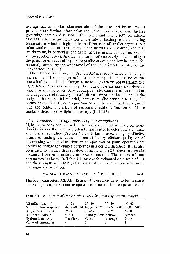
Cement chemistry
average size and other characteristics of the alite and belite crystalsprovide much further information about the burning conditions; factorsgoverning them are discussed in Chapters 1 and 3. Ono (O7) consideredthat alite size was an indication of the rate of heating to the clinkeringtemperature, which if high led to the formation of smaller crystals, butother studies indicate that many other factors are involved, and thatoverturning, in particular, can cause increase in size through recrystalli-zation (Section 3.4.4). Another indication of excessively hard burning isthe presence of material high in large alite crystals and low in interstitialmaterial, formed by the withdrawal of the liquid into the centres of theclinker nodules (L10).
The effects of slow cooling (Section 3.5) are readily detectable by lightmicroscopy. The most general are coarsening of the texture of theinterstitial material and a change in the belite, when viewed in transmittedlight, from colourless to yellow. The belite crystals may also developragged or serrated edges. Slow cooling can also cause resorption of alite,with deposition of small crystals of belite as fringes on the alite and in thebody of the interstitial material, increase in alite crystal size and, if itoccurs below 1200°C, decomposition of alite to an intimate mixture oflime and belite. The effects of reducing conditions (Section 3.4.6) aresimilarly detectable by light microscopy (L11,L13).
4.2.4 Applications of light microscopic investigationsLight microscopy can be used to determine quantitative phase composi-tion in clinkers, though it will often be impossible to determine aluminateand ferrite separately (Section 4.5.2). It has proved a highly effectivemeans of finding the causes of unsatisfactory clinker quality or ofdetermining what modifications in composition or plant operation areneeded to change the clinker properties in a desired direction. It has alsobeen used to predict strength development. Ono (07) described resultsobtained from examinations of powder mounts. The values of fourparameters, indicated in Table 4.1, were each estimated on a scale of 1-4and the strength R, in MPa, of a mortar at 28 days then predicted usingthe regression equation:
* = 24.8 + 0-63AS + 2.15AB + 0-39BS + 2-10BC (4.4)
The four parameters AS, AB, BS and BC were considered to be measuresof heating rate, maximum temperature, time at that temperature and
Table 4.1 Parameters of Ono's method (07) for predicting cement strength
AS (alite size, /mi)AB (alite birefringence)BS (belite size, /mi)BC (belite colour)Hydraulic activityValue of parameter
15-200008-001025-40ClearExcellent4
20-300006-000720-25Faint yellowGood3
30-400005-000615-20YellowAverage2
40-600002-0-0055-10AmberPoor1
96

Properties of Portland clinker and cement
cooling rate, respectively. As noted in the preceding section, the first ofthese assignments is questionable, but this does not necessarily invalidatethe results obtained by the method, which was tested by routineapplication in many plants of a major cement company over a longperiod. Some of the other workers using the method have, in contrast,had little success with it (e.g. S34), and the generality of the procedure, orof the coefficients, remains to be established. The constant term in theequation probably subsumes terms relating to composition and cementfineness, which would have to be taken into account if a wider range ofsamples was considered.
4.3 Scanning electron microscopy, X-ray diffractionand other techniques
4.3.1 Scanning electron microscopyBackscattered electron imaging of polished sections of clinkers in thescanning electron microscope (SEM) provides information essentiallysimilar to that given by light microscopy, with two important additions(S35-S37). First, phases can be analysed chemically. Second, the imagecan be stored electronically and subsequently processed or analysed invarious ways. The method can be used to study ground cements as well asclinkers by dispersing the cement in a resin, which is then allowed toharden. The residual, unhydrated cement grains in a hardened cementpaste can also be examined.
In all cases, the polished section is coated with an electrically con-ducting layer, normally 30 nm of carbon, but not etched. A backscatterdetector is used that maximizes contrast from compositional differencesand minimizes that from topography. Provision for X-ray microanalysisis highly desirable and should include facilities both for obtaining X-rayimages giving semi-quantitative information on the spacial distributionsof individual elements ('dot maps'), and for obtaining complete andquantitative chemical analyses in regions of micrometre dimensions.Techniques are described in standard texts (e.g. G35), and the results ofanalyses of individual clinker phases are considered in Chapter 1.
Figure 4.3 shows backscattered electron images of a typical clinker andof a polymineralic cement grain present in a fresh paste. Cement grainslarger than 2-3 /im are nearly always polymineralic (S37). Phases can, ingeneral, be distinguished by their grey levels. The intensity of theelectrons backscattered from a particular region of a specimen dependsapproximately on the mean atomic number of the material of which thatregion is composed; more precisely, it is represented by the backscatteringcoefficient rj, which may be calculated from the formulae:
V = SCiT/i (4.5)
rj{ = -00254 + 0016Zi - 186 x 10-4Zf + 8-3 x 10⁻⁷Zf (4.6)
where the summation is over elements and Q is the mass fraction of anelement having atomic number Z{ (G35). This equation assumes theaccelerating voltage to be 20 kV. Assuming the typical compositions
97

98

Properties of Portland clinker and cement
given in Table 1.2 for the individual phases, this gives values of 0-171 foralite, 0-167 for belite, 0-168 for cubic aluminate and 0-178 for ferrite. Thedifferences between these values are such that the grey levels of the alite,belite and ferrite phases on micrographs are distinguishable to the eye,but those of belite and aluminate are not; however, the phase boundariesare normally visible, presumably due to slight topographical contrast orcompositional irregularity. The resolution available is limited by the sizeof the region from which the backscattered electrons are produced, whichis somewhat below 1 //m in each direction. Much higher resolution isobtainable using the secondary electron image, but this depends mainlyon topographical contrast and thus gives, at best, poor definition of thephases. The resolution given by the X-ray image is poorer than that givenby the backscattered electron image.
Image analysis makes it possible to quantify images produced by theSEM (Dl 1,L17,S36-S39). It provides a means of quantitative phase deter-mination and can also provide information on such matters as the dis-tributions of shape, size and surroundings of particles and of phases andpores within them or the relative amounts of each of the phases exposedon the surfaces of polymineralic particles. It is, of course, essential toexamine a sufficient number of samples and fields to ensure that theresults are representative, but the labour and subjectivity associated withlight microscopic studies of a comparable nature are largely eliminated.
Scrivener (S36) showed that it was possible to determine the totalcontents of silicate phases and interstitial material by image analysis of acombination of backscattered electron image and X-ray dot maps. Shealso showed that the proportions of interstitial phases exposed on thesurfaces of the grains were significantly greater than those by volume inthe bulk material. Overall, fracture during grinding appeared to bepredominantly through alite, and to avoid phase boundaries. Subsequentdevelopments in image-analysis systems have made it possible to deter-mine the individual clinker phases quantitatively (D11,S38,S39).
4.3.2 X-ray diffractionThe potential uses of XRD powder diffraction in the study of clinker oranhydrous cement include the qualitative and quantitative (QXDA)determination of phase composition, and the determination of polymor-phic modification, state of crystallinity and other features of individualphases. In principle, information on compositions of phases is obtainable
Fig. 4.3 Backscattered electron images of polished sections of (A) a Portlandcement clinker and (B) grains of a Portland cement in afresh paste. In both sections,alite is the predominant clinker phase. In (A), the relatively large, darker areas areofbelite and the interstitial material consists of dendritic ferrite (light) in a matrix ofaluminate (dark); cracks and pores (black) are also visible. In (B), the belite formswell-defined regions, which are rounded, striated and darker than the alite; theinterstitial material present, for example, in a vertical band left of centre withinthe large grain, consists mainly of ferrite (light) and aluminate (dark). From S35.
99
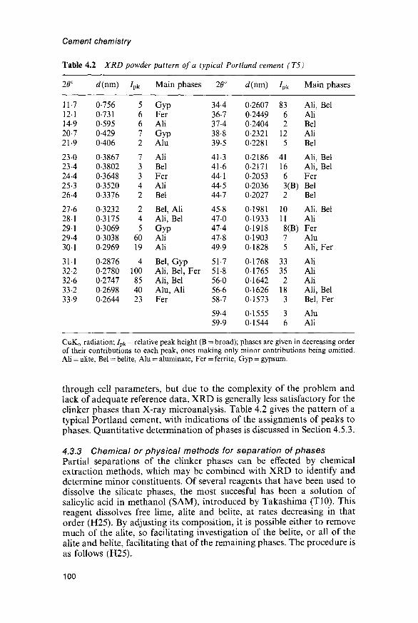
Cement chemistry
Table 4.2 XRD powder pattern of a typical Portland cement (T5)
20°
11-712-114-920-721-9
23-023424425-3264
27-628-129-1294301
31-132-232-633-233-9
d(nm)
0-7560-7310-5950-4290-406
0-38670-38020-36480-35200-3376
0-32320-31750-30690-303802969
0-28760-27800-27470-26980-2644
/Pk
56672
73342
245
6019
4100854023
Main phases
GypFerAliGypAlu
AliBelFerAliBel
Bel, AliAli, BelGypAliAli
Bel, GypAli, Bel, FerAli, BelAlu, AliFer
20°
34-436-737438-839-5
41-341644-144-544-7
45-847-047-447-849-9
51-751-856056658-7
59-459-9
d(nm)
0-26070-24490-24040-23210-2281
0-21860-21710-20530-20360-2027
0-19810-19330-1918019030-1828
0-17680-17650-16420-16260-1573
0-15550-1544
A*
8362
125
411663(B)2
10118(B)75
33352
183
36
Main phases
Ali, BelAliBelAliBel
Ali, BelAli, BelFerBelBel
Ali, BelAliFerAluAli, Fer
AliAliAliAli, BelBel, Fer
AluAli
CuKa radiation; /pk = relative peak height (B = broad); phases are given in decreasing orderof their contributions to each peak, ones making only minor contributions being omitted.Ali = alite, Bel = belite, Alu = aluminate, Fer = ferrite, Gyp = gypsum.
through cell parameters, but due to the complexity of the problem andlack of adequate reference data, XRD is generally less satisfactory for theclinker phases than X-ray microanalysis. Table 4.2 gives the pattern of atypical Portland cement, with indications of the assignments of peaks tophases. Quantitative determination of phases is discussed in Section 4.5.3.
4.3.3 Chemical or physical methods for separation of phasesPartial separations of the clinker phases can be effected by chemicalextraction methods, which may be combined with XRD to identify anddetermine minor constituents. Of several reagents that have been used todissolve the silicate phases, the most succesful has been a solution ofsalicylic acid in methanol (SAM), introduced by Takashima (T10). Thisreagent dissolves free lime, alite and belite, at rates decreasing in thatorder (H25). By adjusting its composition, it is possible either to removemuch of the alite, so facilitating investigation of the belite, or all of thealite and belite, facilitating that of the remaining phases. The procedure isas follows (H25).
100

Properties of Portland clinker and cement
The clinker is ground in propan-2-ol to an average particle size of5 nm. After evaporating off the propan-2-ol, the sample (5 g) is treated for2 h at room temperature with the SAM reagent (300 ml), with constantstirring. The solution, which is now red, is filtered on a No. 4 sinteredglass filter, and the residue washed with methanol and dried at 90°C.If the residue is to be examined by QXDA, the internal standard(e.g. rutile) may be mixed with the sample before the extraction. Forremoval of alite and belite, the salicylic acid content of the reagent is 20 gper 300 ml. For complete removal of the alite, leaving the maximumquantity of belite undissolved, it is 10-15 g, depending on the alitecontent; five times the mass of C3S in the sample, as given by the Boguecalculation, was found to be satisfactory.
A solution of maleic acid in methanol has also been used to dissolve thesilicate phases (Til). This is quicker than the SAM method, but ifthe methanol contains water, ettringite may be formed and water-solublephases, such as K2SO4, lost, while if it is anhydrous, gelling occurs; theSAM method is thus preferable (S40). Extraction of the silicate phases bythe trimethylsilylation method of Tamas et al. (T12; Section 5.5.2) alsoleaves a residue containing the aluminate and ferrite phases.
Gutteridge (G36) found that a solution of sucrose in aqueous potassiumhydroxide (KOSH reagent) dissolves the aluminate and ferrite, leaving thesilicates and minor phases. The clinker or cement (10 g) is reduced tobelow 5 fim by grinding in cyclohexane (20 ml) for 40min in an agateball mill. After evaporating off the cyclohexane in a stream of N2, thesample (9 g) is added to the KOSH solution (30 g of KOH and 30 g ofsucrose in 300 ml of water) at 95°C and stirred for 1 min. The solutionis then filtered and the residue washed in water (50 ml) followed bymethanol (100 ml) and dried at 60°C. By using a combination of the SAMand KOSH procedures, it is possible to produce a residue consistinglargely of belite.
Various solvents may be used to dissolve free lime, which can bedetermined by titrating the resulting solution with a suitable acid. In oneprocedure (J8), the clinker or cement (10g), ground to about 300 m2 kg"1
(Blaine), is treated with anhydrous ethylene glycol (50 ml) at 80-100°Cfor 5 min, using a magnetic stirrer. The solution is then filtered undersuction and the residue washed at least twice with a further 10-15 mlof hot ethylene glycol. The filtrate and washings are diluted with 25 ml ofwater and titrated to phenolphthalein with 0-05M HC1. Other proceduresemploy mixtures of ethanol and glycerol (LI8) or of acetoacetic ester andbutan-2-ol (Franke solvent; F12). If properly used, all give similar results.They also dissolve CH, and have been used to determine this phase inhydrated cements, but their use for this purpose is questionable as theyalso appear to attack other hydration products.
Physical methods are of limited effectiveness for separating the phasesin cement clinker because of the intimate scale on which the latter aremixed; however, Yamaguchi and Takagi (Yl) had some success with theuse of dense liquids. Some concentration of the ferrite phase can beeffected by magnetic separation (M44,Y1).
101

Cement chemistry
4.3.4 Other methodsBensted (B39) described the use of TG in the study of clinkers orunhydrated cements. At 4Kmin~1 in N2 with cements, losses normallyoccur at 100-200°C from gypsum or hemihydrate, 400-500°C from CHand 500-800°C from CaCO3. If a normal, open sample cup is used, thelosses from conversion of gypsum to hemihydrate and from dehydrationof hemihydrate are poorly resolved, making interpretation difficult.Better separation can be achieved by using a sample cup with a top that isclosed except for a narrow exit (S41).
Syngenite, if present, decomposes at 250-300°C. Small amounts of CHcan occur due to hydration, and of CaCO3 due to carbonation duringmilling or storage, impurity in the gypsum, or, where specification allowsit, deliberate addition. The increasing tendency to allow additions ofsubstances other than calcium sulfate may lead to the presence of otherphases detectable by TG. A mass gain at 300-400°C in air that does notoccur in N2 normally indicates that the clinker was made under reducingconditions, but could also conceivably be due to the presence of anexcessive quantity of metallic iron incorporated during milling. In thislatter case it would, of course, not be shown by the clinker.
Applications of IR and Raman spectroscopy to the study of clinkersand unhydrated cements have been reviewed (B40,B41). The laser Ramanmicroprobe, with which regions of micrometre dimensions on a polishedsurface may be examined, has been used to investigate structure andcrystallinity, especially of the alite and belite (C19). Spectroscopicmethods for studying the surface structures and compositions of cementsare considered further in Section 5.8.2.
4.4 Calculation of quantitative phase composition from bulkchemical analysis
4.4.1 GeneralAs seen in Section 4.5.4, there is wide agreement that the Bogue cal-culation gives seriously incorrect results, especially for alite. It has oftenbeen stated that the errors arise because equilibrium is not maintainedduring cooling, but this is only partly correct. Even if equilibrium wasmaintained, all the major phases would contain significant proportions ofsubstituent ions. The calculation gives incorrect results mainly because thephases do not have the compositions assumed for them, and the absenceof equilibrium conditions during cooling merely alters the errors thatarise. In addition, the four major components are not completely con-tained in the four major phases, and errors arise because the bulk analysisis not fully corrected for this.
4.4.2 Modified Bogue calculationThe Bogue calculation is a solution of four linear simultaneous equationsfor four unknowns. Based on an approach due to Yamaguchi and Takagi(Yl), it may be modified (H3,T13) by using the best available estimates
102

Properties of Portland clinker and cement
of the compositions of the four phases instead of those of the purecompounds and by correcting the raw analysis more fully for the presenceof major oxide components in phases other than the four major ones. Formodern, rapidly cooled clinkers of ordinary Portland cements, thecompositions of the phases do not seem to vary excessively, the mostimportant variations in the present context being in the CaO and Fe2O3
contents of the alite (Chapter 1). By following these principles, one mayexpect to obtain results that are substantially more accurate than thosegiven by the orthodox Bogue calculation.
Deductions from the bulk CaO content that may be needed comprisefree lime and any CaO present in CaCO3 (equivalent to the CO2 content),clinker sulfates (calcium langbeinite or anhydrite or both) and, for acement, added calcium sulfate ('gypsum'). Methods for estimating theamounts of CaO in clinker sulfates are suggested in Section 3.5.7. Toobtain the content of CaO present in calcium sulfate added on grinding ofa cement, it is necessary to know either the amount and composition ofthe added material or the SO3 content of the clinker.
Assuming that a modern method of analysis (e.g. XRF) has been used,the SiO2 and A12O3 contents must be corrected for any material present inthe insoluble residue. For a clinker, the latter usually consists largely ofquartz (SiO2), but for a cement it is likely to consist largely of impuritiesin the gypsum, and it is often reasonable to assume that the insolubleresidue is two-thirds SiO2 and one-third A12O3. If classical, wet analysiswas used, these deductions should not be made, but the apparent contentof A12O3 must be corrected for TiO2 and P2O5.
Values are required for the contents of CaO, SiO2, A12O3 and Fe2O3 ineach of the four major phases. For a modern, quickly-cooled ordinaryPortland cement or clinker, the compositions given in Table 1.2 areprobably often a sufficiently good approximation. It may be desirable tomodify them in accordance with the bulk analysis, in ways suggested inSections 1.2.3, 1.3.3, 1.4.4 and 1.5.2 for alite, belite, aluminate and ferriterespectively, those for the CaO and Fe2O3 in the alite being probably themost important. Alternatively, if they are available, compositionsdetermined by X-ray microanalysis of the particular clinker or cementmay be used. The situation with other types of Portland cements orclinkers is considered in Section 4.4.4.
It is then necessary to set up and solve four simultaneous equations,one for each of the four major oxide components. For each equation,there are four terms on the left-hand side, one for each of the four majorphases. The coefficient in each term is the mass fraction of the oxidecomponent in the phase, the unknown is the mass percentage of the phasein the clinker or cement, which has to be determined, and the right-handside is the mass percentage of the oxide component in the material,corrected for any contributions from phases other than the four majorones. As an example, equation 4.7 might be that for CaO in a case forwhich the mass fractions of CaO in the alite, belite, aluminate and ferritewere respectively 0-710, 0-635, 0-566 and 0-475, the total mass percent-age of CaO present in the four major phases was 64-7%, and xY-x4 are
103

Cement chemistry
respectively the mass percentages of alite, belite, aluminate and ferrite inthe material.
0-710xi + 0-635x2 + 0-566x3 + 0-475x4 = 64-7 (4.7)
Similar equations are required for the other three major oxide com-ponents and the four equations are then solved to obtain values of x\-x4.Any standard method of matrix inversion, such as the Gauss-Jordanmethod (N14), may be used for this purpose.
4.4.3 Mass balance calculationsAs a by-product of the modified Bogue calculation described in thepreceding section, it is readily possible to calculate a mass-balance tableshowing how all the oxide components, both major and minor, aredistributed among the major and minor phases. This requires values forthe mass percentages of all the component oxides in each of the phases.Any MgO in excess of that assigned to the major phases is assumed tooccur in periclase. Other constituent phases may include clinker sulfates,gypsum (for a cement), insoluble residue, CaCO3 if present, and any partof the ignition loss not attributable to gypsum or CaCO3. Table 4.3 issuch a table for a typical clinker. The compositions assumed for themajor phases were approximately those given in Table 1.2, and that of thesulfate was obtained as outlined in Section 3.5.7. The sulfate is probablylargely K2SO4 with some Na2SO4 and CaSO4 in solid solution, but couldinclude some Ca langbeinite. The residual for each oxide componentarises from incorrect assumptions regarding the compositions of phasestogether with contributions from any phases not included in thecalculation.
4.4.4 Limitations and modifications of the modified Bogue calculationThe modified Bogue calculation described above appears to give satis-factory results for most modern Portland cement clinkers or cementshaving alumina ratios between about 1 and 4, but the following pointsshould be noted.
(1) If the aluminate phase is orthorhombic, the appropriate com-position (Table 1.2) should be used in the equations. If bothcubic and orthorhombic forms are present, intermediate valuescould be used.
(2) For a sulfate-resisting Portland cement, an appropriate ferritecomposition, such as that given in Table 1.2, should be used. Ifthe result for aluminate is negative, this phase is absent and itmay be useful to replace the coefficients for the aluminatecomposition by ones for a second ferrite composition. Bybracketing the ferrite composition in this way, estimates of boththe content and the composition of the ferrite can be obtained.
(3) The results will be less accurate for slowly cooled clinkers, as thecompositions of the ferrite and possibly also the aluminatephases may differ significantly from those assumed here. Atpresent, there are not enough data to deal with this problem. The
104

Tab
le 4
.3
Dis
trib
utio
n of
oxi
de c
ompo
nent
s am
ong
phas
es i
n a
typi
cal
Por
tland
cem
ent
clin
ker,
cal
cula
ted
from
th
e bu
lk c
hem
ical
an
alys
is
Ali
teB
elite
Alu
min
ate
Fer
rite
Fre
e lim
ePe
ricl
ase
Sulf
ates
Inso
l. re
s.R
esid
ual
Tot
al
Na 2
O
01
00
01
00
00
00
01
00
00
0-3
MgO 0-7
01
01
0-3
00
0-5
00
00
00 1-6
A1 2
O3
0-7
0-3
2-2
2-2
00
00
00
00
00
5-3
SiO
2
168
4-1
0-3
04
00
00
00
01
00
21-6
P2O
5
01
00
00
00
00
00
00
00
00
0-2
so3
01
00
00
00
00
00
0-9
00
00 10
K2O 01
01
00
00
00
00
0-8
00
-01 10
CaO
47-7 8-2
40
4-7
0-9
00
01
00
00
65-6
TiO
2
00
00
00
0-2
00
00
00
00
00
0-2
Mn 2
O3
00
00
00
01
00
00
00
00
00
01
Fe 2
O3
0-5
01
0-4
21
00
00
00
00
00
31
Tot
al
66-7
130
70
9-9
0-9
0-5
1-9
01
01
1001
CD 5. CD"
CO 3R
esul
ts g
iven
as
perc
enta
ges
on
the
igni
ted
mas
s. P
eric
lase
cal
cula
ted
by
diff
eren
ce.
Dis
crep
anci
es i
n to
tals
ari
se f
rom
rou
ndin
g.
5T 0) Q. 8 3 en
O 01
Cement chemistry
method is not applicable without major modification to clinkersmade under reducing conditions. It is doubtful whether theprocedure is applicable to white cements, both for this reasonand also because they may contain glass. In addition, the rangeof applicability of the composition given in Table 1.2 for thealuminate phase in such cements is uncertain.
4.5 Physical methods for determining quantitativephase composition
4.5.1 GeneralThe physical methods that have proved effective for quantitativedetermination of phases in clinkers are based on light microscopy(Section 4.2.1), scanning electron microscopy (Section 4.3.1) and X-raydiffraction (Section 4.3.2). The last of these, in common with calculationfrom the bulk chemical analysis (Section 4.4), is also applicable tocements. Other methods that have been investigated, such as IRspectroscopy, appear to have less potential.
4.5.2 Light microscopyThe phases may be determined quantitatively by point counting(C20,H23). The areas of phases on a polished section of a cement clinkerare proportional to the volumes in the material. Random and systematicerrors arise from imperfect sampling, counting statistics, the presence ofinclusions too small to be observed by this method and incorrectidentifications of phases by the operator. Error from counting statisticsdepends on the number of points, the size of the grid and the grain sizesof the phases; 4000 points normally gives reasonable precision (H23).Systematic errors from incorrect identification of phases generally exceederrors from counting statistics, and give rise to differences in resultsbetween operators (C20). As an alternative to point counting, imageanalysis has been used (M45). With many clinkers, it is impracticable todetermine the aluminate and ferrite phases separately by either method.For alite and belite, and for interstitial material as a whole, both arecapable of giving highly reliable results, assuming in the case of thesilicate phases that they do not contain inclusions of other phases toosmall to be observed.
4.5.3 Quantitative X-ray diffraction analysis (QXDA)The application of this method to clinkers or cements presents severalproblems. Alite is normally so much the predominant phase that itspattern tends to swamp those of the other phases. All the stronger peaksof belite are overlapped by ones of alite. Other difficulties in quantitativeanalysis are caused by variability of patterns of phases due tocompositional or polymorphic variation, and, especially for the ferritephase, peak broadening due to compositional zoning or imperfectcrystallinity. Other problems in quantitative work are those of QXDA ingeneral; e.g. the material must be ground sufficiently finely that primaryextinction of the more intense peaks is minimized, and adequate mixing
106

Properties of Portland clinker and cement
with an internal standard is possible, if one is used, but not so stronglythat crystallinity is reduced. Milling to below 5 /xm in an agate ball millwith cyclohexane as grinding aid, followed by back loading into thesample holder of a diffractometer, has been found satisfactory forspecimen preparation (G33).
Struble (S42) summarized early QXDA studies on clinkers andcements. Most investigators have used some form of the internalstandard method (Kll). Rutile (TiO2) has been widely used as theinternal standard, but other substances, such as Si, KBr, CaF2 andcorundum have also been employed; corundum has the advantage ofgiving no overlaps with important cement peaks up to 60° 20. Themethod in its conventional form, in which only a single peak of thereference standard and of the phase to be determined is used, ismoderately effective for alite, using the peak at approximately 51° 20,assuming that a means of accommodating the splitting of this peak isfound. It is less satisfactory for the aluminate and ferrite, and useless forbelite, because of the weakness of their peaks and interference from thoseof alite.
Berger et al. (B42) pioneered a least-squares procedure in which theprofile of a diffractometer trace was matched with a simulated tracesumming the contributions from the component phases. In a develop-ment of this technique, Gutteridge (G33) collected data over the range of24-39° 20 by step counting at 0-05° intervals using CuKa! radiation.Data for the sample and pure phases, including known quantities ofan internal standard, were stored in a computer and the least-squarescalculation carried out. Auxiliary procedures were devised for dealingwith background levels, adjusting the peak widths and, to some extent,peak positions in the reference patterns to match those in the clinker,and matching the observed and computed patterns. Minor phases,such as lime, periclase, calcium sulfate phases and mineral additions(Chapter 9) could be included in the analysis. Increased computing powerhas allowed later investigators to use wider ranges of 20, with conse-quently improved precision and accuracy (S43,T14).
Instead of matching profiles, observed and calculated intensitiesintegrated over selected ranges of 20 can be matched by least-squaresmethods (K12,T15). In principle, this can avoid problems arising fromvariations in the patterns of the component phases, though at some lossof sensitivity.
With any form of QXDA, it is normally necessary to employ referencestandards that are as near as possible to the phases in the material asregards composition, polymorphism and degree of crystallinity. Thisimplies both knowledge of the characteristics of the particular clinkerunder examination and the ability to prepare the necessary specimens, oralternatively to isolate them physically from the clinker itself. Onesolution (G33) has been to prepare reference patterns for a wide range ofspecimens of each phase and to use those that appear to correspond mostclosely to those present in the clinker under examination. Clinkers forwhich results had been obtained by point counting have also been used
107

Cement chemistry
(K12). In another approach, a standard profile for alite was extractedmathematically from the observed patterns of several Portland cements(T14).
It is also possible to match the observed pattern against a simulatedpattern obtained by summing patterns calculated from the known crystalstructures. This procedure has been used (T15) to match intensities inte-grated over selected ranges of 20. For each calculated pattern, a 'referenceintensity ratio' (H26) was calculated. This is the integrated intensity of thestrongest individual reflection (which may be a component of an overlap)relative to that of the strongest peak of corundum in a 1:1 mixture bymass. The internal standard added to the clinker or cement need not becorundum, provided that its own reference intensity ratio is known.
If calculated patterns and reference intensity ratios are used, therelative proportions of the phases can be determined from the observeddiffractometer trace for a clinker or cement to which no internal standardhas been added. By normalizing the results to some assumed total(e.g. 98% for the four major phases in a clinker or 95% in a cement), it isthus possible to dispense both with reference standards and with aninternal standard. The Appendix gives calculated patterns and referenceintensity ratios for the four major phases.
4.5.4 Comparison of results of different methodsFrom the results of a study in which six clinkers were examined in anumber of different laboratories, Aldridge (A9) concluded that lightmicroscopy gave accurate results for the quantitative determination ofphases in clinkers, assuming an experienced operator and adequatesampling. Results obtained using QXDA varied widely between labora-tories, and it was concluded that, as carried out in most of them, themethod was of low accuracy. One laboratory, however, obtained resultsthat agreed well with those given by microscopy, and which wereconsidered to be accurate. In general, the contents of alite found bymicroscopy were higher than those given by the Bogue calculation.
The results of another cooperative study, in which microscopy andextraction methods were used, showed that the Bogue calculation alwaysgives low results for alite and generally gives high ones for belite whencompared with microscopy (C20). For the aluminate and ferrite phases,agreement was reasonably good. The total contents of silicates,determined by chemical extraction, agreed reasonably well with thosefound by microscopy.
Several early studies using QXDA gave results in fair agreement withthose of the Bogue calculation, but in the light of the above and otherrecent evidence are of doubtful validity. Odler et al (O10) found that alitecontents found either by microscopy or by QXDA were always greaterthan those given by the Bogue calculation. Gutteridge (G33) reached thesame conclusion for QXDA, and also noted that the total amounts ofthe crystalline phases did not vary significantly from 100%. Kristmann(K13) concluded from a study of 39 clinkers that alite and belite weredetermined more satisfactorily by microscopy than by QXDA, but that
108

Properties of Portland clinker and cement
aluminate and ferrite, due to their close admixture, were better deter-mined by QXDA or by determining the total content of interstitialmaterial by microscopy and the relative amounts of its constituent phasesby QXDA of a residue from SAM extraction (Section 4.3.3). His resultsindicated that the values given by the Bogue calculation are low for aliteand aluminate, high for belite, and reasonably satisfactory for ferrite. Themean discrepancy for alite was 8%.
The modified Bogue calculation described in Section 4.4.2 was testedusing Kristmann's data (T13). Agreement was substantially better thanwith the Bogue calculation for alite, belite and aluminate, and about asgood for ferrite. For alite and belite, there was no significant bias relativeto Kristmann's results in either direction. For aluminate, there was apossible tendency to give high results; for ferrite, it was not possible to tellwhether there was bias, due to inadequacies in the experimental data.Good agreement was also obtained in tests on a wide range of cements,using experimental data obtained by Gutteridge (G37) using QXDA.
Taken as a whole, the evidence indicates that all four major phases canbe satisfactorily determined by QXDA if an adequate experimental pro-cedure is employed (e.g. G33) or by calculation. Alite, belite and the totalcontent of interstitial material can also be determined by microscopy.With any of these methods, assuming the best available procedures to beused, the absolute accuracy is probably not better than 2-5% for aliteand belite, or 1-2% for aluminate and ferrite.
4.6 Reactivities of clinker phases4.6.1 Effect of major compositional variationThe ability of a substance to act as a hydraulic cement depends on twogroups of factors. First, it must react with water to a sufficient extent andat a sufficient rate; 7-C2S, which is virtually inert at ordinary tempera-tures, has no cementing ability. Second, assuming that an appropriateratio of water to cement is used, the reaction must yield solid products ofvery low solubility and with a micro structure that gives rise to the requisitemechanical strength, volume stability, and other necessary properties.C3A reacts rapidly and completely with water, but the products that areformed when no other substances are present do not meet these criteria,and its ability to act as a hydraulic cement is very poor. C3S, in contrast,satisfies both sets of conditions, and is a good hydraulic cement.
In this section, only the factors that control reactivity are considered.Any understanding of them must be based on a knowledge of themechanisms of the reactions with water. It is highly probable that theseare in all cases ones in which an essential step is transfer of protons to thesolid from the water, which is thus acting as a Bronsted acid (B43,D12).As an initial approximation, one may consider the problem purely interms of the idealized crystal structures. The reactivities of the oxygenatoms towards attack by protons depend on their basicities, i.e. themagnitudes of the negative charges localized on them. Any structuralfeature that draws electrons away from the O atoms renders them lessreactive, the basicity thus depending on the electronegativities of the
109

Cement chemistry
atoms with which they are associated. In this respect, the nearest neigh-bours are the most important, but the effects of atoms further away arefar from negligible. This hypothesis leads to the folowing predictions, allof which agree with the facts.
(1) O atoms attached only to atoms of a single element will be lessreactive as the electronegativity of that element increases. Thus,C3S and lime both contain O atoms linked only to Ca, and aremore reactive than /3-C2S, in which all the O atoms are alsolinked to Si, while a-Al2O3, in which all are linked to Al, is inert.However, the reactivity of lime decreases if it is strongly burned;this is discussed below.
(2) O atoms forming parts of silicate, aluminate or other anionicgroups will be less reactive as the degree of condensation withother such groups increases. /3-C2S, in which the tetrahedra donot share O atoms, is more reactive than any of the C3S2 or CSpolymorphs, in which they do.
(3) O atoms forming parts of anionic groups similar as regardsdegree of condensation will be less reactive as the central atoms inthe groups become more electronegative. In contrast to the C3S2
and CS polymorphs, CA, Ci2A7 and C3A are all highly reactive,even though the A1O4 tetrahedra share corners in all cases.
Other hypotheses based on considerations of crystal structure have beenproposed, and in varying degrees may account for second-order effects.Thus, Jeffery (Jl) suggested that irregular coordination of Ca wasresponsible for the high reactivity of C3S as compared with 7-C2S;however, lime reacts with water, but the coordination of its Ca atoms ishighly symmetrical. Jost and Ziemer (J9), who noted the weaknesses inthis and other earlier hypotheses, considered that high reactivity wasassociated with the presence of face-sharing polyhedra, but lime containsno such groupings, yet can be highly reactive.
4.6.2 Effects of ionic substitutions, defects and variation in polymorphThe considerations discussed in the preceding section suffice only toexplain the effects on reactivity of major variations in composition. Theydo not, in general, explain the effects of variations in polymorph orintroduction of substituent ions. These effects are often complex, andwhile in some cases the results appear clear-cut, there are many others inwhich they present a confusing and sometimes apparently contradictorypicture. The probable reason is that many variables are involved, whichare difficult or impossible to control independently. These include,besides chemical composition and polymorphic change, concentrationsand types of defects; particle size distribution; textural features such ascrystallite size and morphology, mechanical stress, presence of micro-cracks and the monocrystalline or polycrystalline nature of the grains;influences of reaction products, whether solid or in solution. In a cementas opposed to a pure phase, a foreign ion may not only substitute in aparticular phase, but also influence the microstructure of the material in
110

Properties of Portland clinker and cement
ways unconnected with that substitution, e.g. by altering the physicalproperties of the high-temperature liquid present during its formation.For both microstructural and chemical reasons, the reactivity of a givenphase in a cement may not be the same as that observed when it is alone.
Defects play a particularly important role. Sakurai et al. (S44) notedthat C3S, alite, C2F and C4AF could all take up Cr2O3 and that thisgreatly accelerated reaction at early ages. Electron microscopic studiesshowed that reaction began at grain boundaries and at points ofemergence of screw dislocations, the concentration of which was greatlyincreased by Cr2O3 substitution. It was also shown that the substitutedmaterials were semiconductors, and a mechanism of attack based onelectron transfer processes was suggested. Fierens and co-workers(F13,F14) also found that the influence of substituent ions on thereactivity of C3S was due to the presence of defects, which could bestudied using thermoluminescence, and which could also be introducedby suitable heat treatment.
The complex relations between content of substituent ions, poly-morphism, defects and reactivity are well illustrated by the results ofBoikova and co-workers (B2,B44) on ZnO-substituted C3S. Withincreasing ZnO content, triclinic, monoclinic and rhombohedral poly-morphs were successively stabilized. Curves in which the extent ofreaction after a given time were plotted against ZnO content showedmaxima corresponding approximately to the T2-M! and M2-R transi-tions, with intermediate minima. As in the work mentioned above, it wasshown that these compositions were also ones in which the numbers ofdefects of a particular type were at a maximum. Reactivity thus dependsnot so much on the amount of substituent or nature of the polymorph ason the types and concentrations of defects.
Studies on the comparative reactivities of the /?-, af- and a-C2S,reviewed by Skalny and Young (S45), have given contradictory results.As these authors conclude, reactivity probably depends on specimenspecific factors other than the nature of the polymorph, and in the lowertemperature polymorphs may be affected by the exsolution of impurities.This latter hypothesis receives strong support from subsequent observa-tions that attack begins at exsolution lamellae and grain boundaries, andthat these may contain phases, such as C3A, that are much more reactivethan the C2S (Cl). Without these lamellae, /3-C2S might be much lessreactive than it is.
There is wide agreement that substitution of alkali metal ions retardsthe early reaction of the aluminate phase, which is thus less for theorthorhombic than for the cubic polymorphs (B45,R14,S46). The effecthas been attributed to structural differences, but the early reaction ofpure C3A is also retarded by adding NaOH to the solution, and the OH~ion concentration in the solution may be the determining factor (S46).The reaction of C3A is also retarded by iron substitution and by closeadmixture with ferrite; formation of a surface layer of reaction productsmay be a determining factor, at least in later stages of reaction, and theretarding effect of such a layer may be greater if it contains Fe3+ (B46).
111

Cement chemistry
4.6.3 Ferrite reactivity; effect of complexing in solutionThe reactivities of ferrite phases in the pure Ca2(AlxFei_x)2O5 series havebeen widely found to increase with Al/Fe ratio, and material ofcomposition similar to that in clinkers is more reactive than eitherC4AF or C6A2F (e.g. B45,B46,D13). Anomalies in the relation betweenrate and Al/Fe ratio found by some workers can possibly be attributed tozoning or other variations in crystallinity. As with the aluminate phase,the decrease in reactivity with Fe content is possibly explainable by differ-ences in the properties of a retarding layer of product. The relatively highreactivity of the clinker material may be related to its semiconductingproperties (M24) and to disorder arising from the complex ionicsubstitutions (B46).
The rate of reaction of the ferrite phase is much increased by thepresence of tri-isopropanolamine in the solution. This is not stronglyadsorbed on the cement grains but complexes the iron in solution, therebyinhibiting the formation of a layer of reaction product and favouring thepassage of iron into solution (G38). This illustrates the important factthat the rate of reaction is not solely controlled by properties of the solidphase but depends also on what is present in the solution.
112

5 Hydration of the calciumsilicate phases
5.1 Introduction5.1.1 Definitions and general pointsIn cement chemistry, the term 'hydration' denotes the totality of thechanges that occur when an anhydrous cement, or one of its constituentphases, is mixed with water. The chemical reactions taking place aregenerally more complex than simple conversions of anhydrous com-pounds into the corresponding hydrates. A mixture of cement and waterin such proportions that setting and hardening occur is called a paste, themeaning of this term being extended to include the hardened material.The water/cement (w/c) or water/solid (w/s) ratio refers to proportions bymass; for a paste, it is typically 0-3-0-6. Setting is stiffening withoutsignificant development of compressive strength, and typically occurswithin a few hours. Hardening is significant development of compressivestrength, and is normally a slower process. Curing means storage underconditions such that hydration occurs; conditions commonly employed inlaboratory studies include storage in moist air initially and in water afterthe first 24 h, storage in air of 100% relative humidity and, less favour-able for reaction, storage in a sealed container.
Because Portland cement is a relatively complex mixture, many studieshaving the aim of elucidating its hydration chemistry have been made onits constituent phases. For a given particle size distribution and w/s ratio,tricalcium silicate or alite sets and hardens in a manner similar to that ofa typical Portland cement. Using XRD or other methods, it may beshown that about 70% of the C3S typically reacts in 28 days and virtuallyall in 1 year, and that the products are calcium hydroxide (CH) and anearly amorphous calcium silicate hydrate, called C-S-H, having theproperties of a rigid gel. f3-C2S behaves similarly, but much less CH isformed and reaction is slower, about 30% typically reacting in 28 daysand 90% in 1 year. Figure 5.1 shows the XRD diffraction pattern of a23-year old paste of /?-C2S. Patterns of fully reacted C3S pastes aresimilar, except that the CH peaks are much more intense. The only effectsdefinitely attributable to the C-S-H are the diffuse peak at 0-27-0-31 nmand the somewhat sharper one at 0-182nm.
113

Cement chemistry
60° 28
Fig. 5.1 XRD powder diffraction pattern (microdensitometer trace ofGuinierfilm,CuKQi radiation, spacings in A) of a fully reacted (3-C2S paste. From M46.
For both C3S and /?-C2S, reaction rates depend on particle size distri-bution and other factors. Development of compressive strength runsroughly parallel to the course of the chemical reactions, and the strengthsat 1 year are comparable to those of Portland cements of the same w/sratio and cured under the same conditions.
The calcium silicate hydrate formed on paste hydration of C3S or/3-C2S is a particular variety of C-S-H, which is a generic name for anyamorphous or poorly crystalline calcium silicate hydrate. The dashesindicate that no particular composition is implied, and are necessarybecause CSH in cement chemical nomenclature denotes material specifi-cally of composition CaO • SiO2 • H2O. The term 'C-S-H gel' is some-times used to distinguish the material formed in cement, C3S or /?-C2Spastes from other varieties of C-S-H.
This chapter deals primarily with the reactions and products ofhydration of C3S and /3-C2S in pastes at ordinary temperatures. Someclosely related studies on cement pastes are also considered. Most of theresults for pastes of C3S or /3-C2S are applicable also to the behaviourof those phases in cement pastes. Except where stated, a temperature of15-25°C is assumed. Background information has been obtained fromstudies of C3S or /3-C2S hydration at higher w/s ratios, i.e. in aqueoussuspensions, or on C-S-H prepared in other ways, and the results ofsuch studies are also considered.
5.1.2 Experimental considerations; carbonationC-S-H reacts with CO2 or CO^~ ion with formation of CaCO3. Initially,the Ca/Si ratio of the C-S-H decreases; further reaction destroys theC-S-H, with formation of hydrous silica. Contamination by atmo-spheric CO2 ('carbonation') can probably be more serious in laboratorystudies than in practical concrete mixes of lower surface to volume ratio.Many studies have been made under, as nearly as possible, CO2-freeconditions. This has the merit of simplifying interpretation, though theextent to which it corresponds to the situation in a real concrete mix isuncertain. To achieve a reasonable approximation to CO2-free condi-tions, all operations, such as mixing, curing or drying of pastes, orpreparation, filtration or drying of solid phases in suspensions, must becarried out in a CO2-free atmosphere, either in a dry box or in apparatusotherwise designed to isolate the materials from the atmosphere. Wet or
114

Hydration of the calcium silicate phases
moist materials are especially susceptible to attack, but dry ones are notimmune. Water must be deionized and freshly boiled. Because of thealkaline nature of calcium silicate or cement mixes, prolonged contactwith glass must also be avoided; wet curing may be carried out in thepresence of a small excess of water in a sealed plastic container.
In any laboratory study, therefore, it is usually important to know howmuch CO2 is present. This applies both to situations in which it issupposedly absent and to those in which an attempt has been made toinclude a controlled quantity. Jones's (J10) method, based on decom-position with dilute acid and absorption of the CO2 in Ba(OH)2 solution,which is then back-titrated with HC1, is simple and accurate. TG hasoften been used to determine CO2, but is not satisfactory because the lossat 700-900°C is not wholly due to CO2. Absence of calcite peaks from anXRD pattern is not a proof that CO2 is absent, as CO2 can occur in otherforms, e.g. as vaterite (/i-CaCO3), in calcium aluminate hydrate phasesand possibly within the C-S-H structure. Table 5.1 gives data for thethree polymorphs of CaCO3 that can form at ordinary pressures.
Especially with relatively young pastes, the problem often arises ofremoving excess water after a specified time of curing to stop the hydra-tion reactions and to render the material less susceptible to carbonation.For this purpose, soaking or grinding in polar organic liquids, such asmethanol, propan-2-ol or acetone has often been employed, but should
Table 5.1 Crystal and optical data for calcium carbonate polymorphs
Crystal dataCrystal system
Space groupa (nm)b (nm)c (nm)Angles, wherenot 90°ZA^kgm-3)Reference
Optical propertiesRefractive indices(Nap)Optic orientationOptic signMorphology
Reference
Calcite
Trigonal(rhombohedral)R3c0-4989
1-7062120° (7)
62711PI (card 5-586)
UJ 1-6584, e 1-4864
NegativeRhombs( Q R 101-9°)
W3
Aragonite
Orthorhombic
Pmcn0-496230-79680-57439
42927PI (card 41-475)
a 1-5300,/? 1-681,7 1-6854X=c, Y=a, Z = bNegative (2 V= 18°)Short columns,needles
W3
Vaterite
Hexagonal
P63/mmc0-71473*
1-6917*120° (7)
122664PI (card 33-268)
u 1-550,e 1-640-1-650
PositivePlates, radialaggregates
W3
* Other poly types and disordered forms are known.
115

Cement chemistry
be used only in situations where it will not invalidate the results ofsubsequent tests. Organic substances can be completely removed fromC3S or cement pastes only by drastic procedures that seriously alter thematerial. Their presence is especially undesirable if any form of thermalanalysis (e.g. TG or DTA) is to be carried out, since on heating they reactwith C-S-H to give CO2 (D14,T16). Acetone has especially complexeffects, since in the alkaline medium it rapidly undergoes aldol conden-sations at room temperature, giving mesityl oxide, phorone and otherrelatively involatile products (T16). Some workers consider that primaryaliphatic alcohols alter the pore structures of C3S or cement pastes or ofsynthetic C-S-H preparations (Section 8.4.1), and it has also beenclaimed that methanol reacts with CH at ordinary temperatures, givingcalcium methoxide (B47).
In choosing a procedure to remove excess water, it is necessary toconsider the likely effects on the tests subsequently to be performed.Retention of organic substances is not the only possible complication;unduly drastic drying procedures, e.g. heating at 105°C or equilibration toconstant mass in atmospheres of low relative humidity, such as 'D-drying'(Section 5.2.2) partially dehydrate the C-S-H and, with cement pastes,also partially decompose the hydrated calcium aluminate or aluminatesulfate phases. For some procedures, such as XRD, the presence oforganic material may not matter, but even here the possibility of decom-posing or altering hydrated aluminate phases must be considered. Forelectron microscopy, including the preparation of polished sections forSEM, freeze-drying has been found satisfactory (Jll). For many pur-poses, including thermal analysis above about 150°C, pumping with arotary pump for 1 h is suitable. The drying of samples for studies on porestructure is considered in Section 8.4.1.
All analytical data on hydrated cements or cement constituents shouldnormally be referred to the ignited mass. The original mass includes anarbitrary amount of water, and results referred to it, or to the mass aftersome arbitrarily chosen drying procedure (e.g. to constant mass at 105°C),are often impossible to interpret in detail.
5.7.3 Calcium hydroxideCH has a layer structure (Fig. 5.2; B48,P18). The calcium atoms areoctahedrally, and the oxygen atoms tetrahedrally, coordinated. Theinterlayer forces are weak, with negligible hydrogen bonding, thus givinggood (0001) cleavage. The unit cell is hexagonal, with a = 0-3593 nm,c'= 0-4909nm, space group P3ml, Z = 1, Z)* = 2242 kg m"3 ; the opticalproperties are: uniaxial - , UJ= 1-573, e = 1-545 (S8). Calcium hydroxide isoften described by its mineral name, portlandite.
Under ideal conditions of crystallization, CH forms hexagonal plates.Admixtures greatly affect the morphology, and especially the c: a aspectratio (B49). Euhedral crystals are observed in young pastes and in poresof older pastes, but as hydration proceeds the main deposits of CHbecome massive and of indeterminate shape, though the good cleavagepersists. There does not appear to be any convincing experimental
116

Hydration of the calcium silicate phases
Plan
Elevation
Fig. 5.2 Structure of a single layer of Ca(OH)2. Small, solid circles representcalcium atoms, large open or shaded circles oxygen atoms; a hydrogen atom, notshown, completes the tetrahedral coordination of each oxygen atom. From T17.
evidence for claims that some of the CH in calcium silicate pastes isamorphous. A TEM study of ion-thinned sections of a C3S paste ofnormal w/s ratio showed the CH to occur as large, imperfect crystals; nofinely dispersed, microcrystalline materials were observed, though somecrystals were only tens of nanometres thick (G39,G40). CryptocrystallineCH has, however, been found in cement pastes and in pastes made fromcalcium oxide and silica of high w/s ratio and of blastfurnace slagactivated by CH (Section 7.1.1).
Observations that the 0001 peak of CH in XRD powder patterns ofcalcium silicate or cement pastes is anomalously strong relative to the1011 peak (G41,Z10) have been attributed to overlap with a contributionfrom C-S-H, but probably arise from preferred orientation, which canbe difficult to avoid. Stacking faults can also affect the CH pattern (S47).
The dissolution of CH in water is exothermic (AH = — lSSkJmol"1 at25°C; G42), and the solubility therefore decreases with temperature(Table 5.2). The data given are for large crystals; higher apparentsolubilities, up to at least 1-5 g CaO per 1 at 25°C, readily occur with finelycrystalline material.
Table 5.2 Solubility of calcium hydroxide (S; g CaO l'x; B50)
T(°C) 0 5 10 15 20 25 30 40 50 60 80 99S 1 30 1-28 1-25 1-21* 117* 113 109 100 0-92 0-83* 0-66* 0-52
* Interpolated values.
117

Cement chemistry
i
500 700 900Temperature (°C)
Fig. 5.3 Thermogravimetric curve of Ca(OH)2 (0.2% CO2); data are expressedas percentages on the ignited mass. 50mg sample heated at 10Kmin~l in dry,CO2-free N2 flowing at 15mlmin~x. New data.
Halstead and Moore (H27) reported thermal decomposition equilibria.The decomposition pressure reaches 101 kPa (1 atm) at 512°C and themean enthalpy of decomposition at 300-510°C is 102-9 kJmor1. Whenheated in a vacuum or in a stream of dry N2, CH begins to decompose atan easily detectable rate at about 370°C. Under typical conditions forTG, decomposition is 98% complete at the end of the step at 580°C(Fig. 5.3). An earlier conclusion that only about 94% has decomposed atthis point (T18) is incorrect. The finely divided CH available as alaboratory or analytical reagent normally contains several per cent ofCaCO3, and the curve in Fig. 5.3 is for coarsely crushed large crystalscontaining 0.2% CO2.
5.2 Composition, density and other data for C-S-H gel5.2.7 Calcium hydroxide content, thermal analysis and indirect
determination of the Ca/Si ratioThe Ca/Si ratio of the C-S-H in a fully reacted C3S or /3-C2S paste maybe calculated if the contents of CH and CO2 are known, though anassumption must be made as to whether the CO2 occurs in the C-S-H oras CaCO3. If the content of unreacted C3S or /3-C2S is also known, themethod can be extended to incompletely reacted pastes, though smallerrors in the contents of CH or unreacted starting material greatly affectthe result at low degrees of reaction. Quantitative XRD is probably thebest method available at present for determining unreacted C3S or /3-C2S;the precision is probably not better than ±3% (Oil). Methods used todetermine CH have included TG, DTG, semi-isothermal DTG, thermalevolved gas analysis, DTA, differential scanning calorimetry (DSC),quantitative X-ray diffraction analysis (QXDA), IR spectroscopy, image
118

Hy drat ion of the calcium silicate phases
analysis of backscattered electron images and extraction methods usingeither aqueous media or organic solvents similar to those used todetermine free lime in anhydrous cements.
Some workers studying pastes of C3S or cement have found significantdifferences between the results of thermal methods and QXDA, the latterusually giving lower results for the CH content (B51,D15,M47,O11,R15),but others have found no differences outside experimental error (L19,T19).There is broad agreement that extraction methods give higher results thaneither thermal methods or QXDA (B51,M47,O11,R15). It has beensuggested that QXDA gives low results due to the presence of amorphousCH (R15). Thermal methods have also been considered to give low resultsfor the same reason (Oil), or because of CH adsorbed on the C-S-H (B51)or present as interlayer material (S48). Sources of error in CH determina-tion by TG have been discussed (T18). As noted above, large errors canarise from use of thermal methods on material that has been in contact withorganic liquids (T16). Preliminary results from image analysis did notcorrelate well with those from TG (S49).
The borderline between CH interlayered with C-S-H and that presentas a separate phase is indistinct. The absence of evidence for amorphousor cryptocrystalline CH in C3S pastes is noted in Section 5.1.3. Thehigher results given by extraction methods are probably attributable topartial decomposition of the C-S-H. Of all the methods, TG or DTG isprobably the least open to criticism, though, especially with cementpastes, precision and accuracy are limited by the difficulty of disting-uishing sharply between the effects due to CH and to the other phasespresent. DTA is somewhat suspect, because the peak area for CH isreported to depend markedly on particle size (W18).
Figure 5.4 shows the TG and DTA curves of a fully reacted C3S paste,obtained under the same conditions as the TG curve of CH in Fig. 5.3.The paste had been prepared at w/s = 0-45 and stored wet, in a sealedcontainer for 25 years at 25°C; it contained 0-8% of CO2, referred to theignited mass. The height of the CH step (mean from 7 determinations andestimated as shown in the inset) was 8-9%, referred to the ignited mass.Assuming that this step represents the decomposition of 98% of the CHand that the CO2 occurs as CaCO3, there is M5mol CH and 004molCaCO3 per mole of C3S, and the Ca/Si ratio of the C-S-H is 1-81. Otherrecent investigations on C3S or /3-C2S pastes have indicated Ca/Si ratiosranging from 1-6 to 20 (F15,K14,L19,O11,P19,S23). There is evidence ofa lower Ca/Si ratio during the first few hours of reaction (Oil), but withthat reservation the more recent work (L19,O11,P19) does not supportthe conclusion of some earlier workers that the ratio changes markedlyduring the course of the reaction.
5.2.2 Water contentEvidence considered in Sections 5.3 and 5.4 and Chapter 8 indicates thatthe C-S-H gel of calcium silicate or cement pastes has a layer structure,and that, together with a pore solution, it forms a rigid gel in which thepores range in size from macroscopic to enlarged interlayer spaces of
119

Cement chemistry
800 1000400 600Temperature (°C)
Fig. 5.4 Thermogravimetric and differential thermal analysis curves for a fullyreacted C3S paste; experimental conditions as for Fig. 5.3. TG data are expressed aspercentages on the ignited mass. After T16.
nanometre dimensions. One can therefore define a water content only inrelation to a specified drying condition. Three such conditions will beconsidered.
The most highly hydrated state is that existing in a saturated paste, i.e.one in which the pores are totally filled with water. According to thetheory of Powers and Brownyard (P20; Section 8.2.1), the C-S-H in acement paste can form only if sufficient space is available to permit it tobe accompanied by a defined proportion of pore space. There is thus acertain w/c ratio below which complete hydration is impossible, and forwhich a mature paste consists entirely of hydration product, includingthis essential pore space. The total water content of such a paste in thesaturated condition is typically 42-44%, referred to the ignited mass. Fornearly saturated C3S pastes, Young and Hansen (Y5) concluded that thecomposition of the C-S-H was approximately l-7CaO'SiO2*4H2O.Taking into account the water present in the CH, this corresponds to aw/c ratio of 0-42, which is similar to the values found for cement.
Chemically bound water is most reasonably defined as including thatpresent in interlayer spaces, or more firmly bound, but not that present inpores larger than this. As will be seen in Chapter 8, the distinctionbetween interlayer space and micropores is not sharp; water adsorbed onsurfaces of pores further blurs the definition. From the experimentalstandpoint, the determination is complicated by the fact that the amountof water retained at a given RH depends on the previous drying history ofthe sample and on the rate at which water is removed. An approxi-mate estimate is obtained by equilibrating a sample, not previously dried
120

Hydration of the calcium silicate phases
below saturation, with an atmosphere of 11% RH (F16-F18). Saturatedaqueous LiCl • H2O gives the required RH (partial pressure of watervapour = 2-7 torr at 25°C). To achieve apparent equilibrium in areasonable time (several days), the sample must be crushed and the sys-tem evacuated; the salt solution should be stirred, at least intermittently.Young and Hansen (Y5) found the composition of the C-S-H in C3Spaste thus equilibrated to be 1 7CaO-SiO2-2 1H2O.
As noted above, treatment of C3S pastes with methanol leaves some ofthe latter strongly sorbed. The methanol is removable only on heating attemperatures at which it reacts with the C-S-H, causing carbonation.However, the total mass of volatiles retained in a C3S paste that has beensoaked in methanol and then pumped for about 1 h with a rotary pump isnear that obtained on equilibration with saturated LiCl*H2O (T16).Methanol treatment can thus be used as a rapid, though approximatemethod of determining chemically bound water. Other organic liquidscould possibly be used in a similar way.
In a procedure known as 'D-drying', the sample is equilibrated with iceat — 79°C by continuous evacuation with a rotary pump through a trapcooled in a mixture of solid CO2 and ethanol (C21). The partial pressureof the water vapour is 5 x 10~4torr. Heating to constant mass at 105°C inan atmosphere of uncontrolled humidity, but free from CO2, reduces thewater content to approximately the same value, although it is not astrictly defined drying condition. The corresponding temperature on aTG curve obtained in dry and CO2-free N2 at 10 Kmin"1 is about 145°C,but depends on the rate of gas flow and design of the apparatus. Waterretained in pastes subjected to D-drying or equivalent procedures isknown as 'non-evaporable' water. Contrary to some statements in theliterature, it is not a measure of chemically bound water, as much wateris lost from interlayer spaces under these conditions. It can neverthelessbe used as an empirical measure of the degree of reaction. Typical valuesin the literature for the water contents of fully reacted C3S pastes driedby these procedures are 204-220% (Oil), corresponding to C-S-Hcompositions of 17CaO-SiO2-1-3—1 5H2O.
Powers and Brownyard (P20) called the water lost from the C-S-Hon passing from the saturated to the D-dry condition 'gel water'. It com-prises part of the pore water plus an arbitrarily defined fraction of theinterlayer water. Whatever procedure is used to dry or equilibrate a paste,CO2-free conditions are essential, and the amount of water retained canbe obtained accurately only if the ignition loss and CO2 content are alsodetermined. Calculations based on the initial w/s ratio are often unreli-able due to changes in the water content during curing.
5.2.3 Density and infrared spectraThe density of C-S-H gel depends on the water content. For stronglydried samples, it also depends on how the solid volume is defined, causingobserved values to vary with the fluid used in their determination. Widelydiffering values can be equally meaningful, but for a given application theappropriate one must be used. Since the C-S-H of C3S or /?-C2S pastes is
121

Cement chemistry
mixed with CH, it is necessary to correct for this phase (D = 2242 kgm~3)or to remove it. Ramachandran (R15) described a way of doing this.
At about 11% RH on first drying, the interlayer spaces are full ofwater and larger spaces are empty; H2O/SiO2 is approximately 2-0(Section 5.2.2). Using helium pyknometry, Feldman (F19) obtainedvalues of 2350-2360 kg m"3 for fully reacted C3S pastes; correction forCH gave 2430-2450 kg m"3 for the C-S-H. Determinations on C-S-Hsamples made by hydrating C3S in suspension showed that substitutionof methanol or aqueous CH for helium as the fluid had no significanteffect on the result. For a fully hydrated C3S paste with w/s = 0-4 fromwhich the CH had been removed, Hansen (H28) found 2180kgm~3. Forall these values, empty pores are excluded from the solid volume.
The C-S-H present in a saturated paste is assumed to include that part ofthe porosity, and its content of water, without which it cannot be formed.The H2O/SiO2 ratio is approximately 4-0. Assuming the water in excess ofthat present at 11% RH to have a density of lOOOkgm"3, Hansen (H28)calculated the density of the C-S-H to be 1850-1900 kg m"3. This value isnear the values of 1900-2100 kg m~3 for cement pastes under saturatedconditions (P20), if allowance is made for the CH and other hydratedphases that they contain.
Helium pyknometry of D-dried samples has given values of 2320-2350kgm~3 for C3S pastes (F19) and of 2440kgm~3 for cement pastes(P20); correction for CH and other phases suggests values of 2400-2500 kg m~3 for the C-S-H. For a C3S paste with w/s 0-4 from which theCH had been removed, Hansen (H28) found 2390 kg m"3. With D-driedsamples, methanol gives results similar to helium, but water or CH solutiongives much higher values, Brunauer and Greenberg (B52) obtaining valuesaround 2860 kg m~3, after correction for CH, for the C-S-H of C3S orf3-C2S pastes. Determinations using water on D-dried cement pastes,based on the difference between the masses of the D-dried and saturatedmaterials, typically give values, uncorrected for CH and other phases, of2500-2600 kg m"3. Relis and Soroka (R16) found these to increase withthe degree of hydration, an upper limit of 2700 kg m~3 being found for aspecific cement.
Feldman (F19) explained the difference between the values for D-driedsamples obtained with aqueous and other fluids. When the material isdried, the layers partially collapse, and some empty spaces remain betweenthem. Water penetrates into these spaces, and the density obtained, aftercorrection for CH and any other phases present, is that of the layersthemselves. Organic liquids do not penetrate, and helium penetrates onlyslowly. The empty interlayer space is counted as part of the solid volume,with a consequent decrease in the measured density.
The IR absorption spectra of pastes of C3S, alite, or /3-C2S(H29,L20,S50), are relatively diffuse, as would be expected from thepoor crystallinity. Si-O stretching is represented by a single, broad bandpeaking at about 970 cm"1; this is compatible with the existence ofcondensed silicate anions. Small amounts of carbonate are readilydetectable by the absorption near 1400 cm"1.
122

Hydration of the calcium silicate phases
5.3 Microstructure, microanalysis and electron diffraction5.3.7 MicrostructureThe first effective studies of microstructural development in calciumsilicate pastes were made using light microscopy of thin sections (B53).They showed that the CH grows from relatively few centres in the water-filled space, where it forms isolated masses typically some tens ofmicrometres in size. Much more CH is observed with C3S than with/3-C2S. At the same time, gel forms around the anhydrous grains andspreads into the remainder of the water-filled space. Early TEMexaminations of ground and redispersed material showed the presenceof acicular and rounded, platey particles, but could not show where thesecame from in the microstructure (C22,G43). SEM studies of fracturesurfaces (C23,D16,G44,W19) confirmed these conclusions and showedalso that the gel formed in situ from the larger anhydrous grains, called'inner product', differed in texture from the 'outer product' formed in thewater-filled space. It was massive and seemingly almost structureless,whereas the outer product appeared to form columns or fibres radiatingfrom the anhydrous grains.
Diamond (D16) distinguished four morphological types of C-S-H gelvisible by SEM on fracture surfaces of cement pastes; similar forms havebeen observed in calcium silicate pastes (Fig. 5.5). Type I, prominent atearly ages, was the fibrous material, the fibres being up to about 2 /xm long.Type II, described as forming honeycombs or reticular networks, was con-sidered to be very rare in pure calcium silicate pastes, but later work showedthat material resembling it is a normal early product. Type III, prominent inolder pastes, was more massive and appeared to consist of tightly packedequant grains up to 300 nm across. Type IV, still more featureless andmassive, was the inner product, and was also observed in older pastes.
SEM of fracture surfaces has provided valuable information, but itsutility is lessened by the inherently unrepresentative nature of a fracturesurface and by the effects of dehydration in the high vacuum of the instru-ment. Further information has come from the use of other techniques,especially high-voltage transmission electron microscopy (HVTEM) withenvironmental or 'wet' cells to reduce water loss (D17,G45,J12), examina-tion of ion-thinned sections by TEM or scanning transmission electronmicroscopy (STEM) (D18,G39,R17,V4), and backscattered electron imag-ing (BEI) of polished sections with detectors that minimize contrast dueto topography and maximize that due to compositional differences(S35,S37,S49). Scrivener and Pratt (S51) briefly described these techni-ques. Other methods have included X-ray imaging of polished surfaces(T20), SEM of polished surfaces impregnated and etched to reveal poros-ity (J13,J14) and use of a cryo stage in the SEM to avoid dehydration(B54). Each of these methods has its own limitations, but together theyhave yielded a reasonably clear picture.
5.3.2 Stages in microstructural developmentJennings et al. (J l l ) distinguished three principal stages of productformation in C3S pastes: an early product formed during the first 4h, a
123

Cement chemistry
B
Fig. 5.5 (A,B) Types I and II C-S-H respectively (SEM of fracture surfaces,courtesy K.L. Scrivener). (C,D) SEM/STEM pair of ion-beam thinned section,showing Type HI C-S-H (top, right) and Type IV C-S-H (top, left and bottom,right; JII). (A) is oj an ordinary Portland cement paste, w/c = 0-5, aged lOh. (B) isof a paste of an oil well cement, w/c = 0-44, with 2-4% of CaCl2 on the mass ofcement, aged 1 day. (C) and (D) are of a C3S paste, w/c = 0-47, aged 330 days.
middle product formed at 4-24 h, and a late product formed subsequently.Several workers studying the hydration of C3S in pastes or compactedpowders placed in water have described the early product as consisting offoils, flakes or honeycombs, which appear to exfoliate from the C3S surface,
124

Hydration of the calcium silicate phases
cFig. 5.5 (continued)
probably together with some CH (F20,G40,H30,Jll,M48,M49,S52).The honeycomb material is similar to Type IF C-S-H, and the foils havealso been called Type E' C-S-H (Jl 1). On drying, they collapse, crumpleor roll up, forming fibres (Jl 1). Broadly similar results have beenobtained for C3S hydrated in CH solution (M49) or in the presence ofgypsum (M50), sodium silicate or sodium aluminate (J15). The earlyhydration of /3-C2S appears to follow a similar course to that of C3S, butreaction is slower and begins preferentially at grain boundaries andexsolution lamellae (G45,M51).
The C3S surfaces are attacked unevenly (H30,M48,M49). Menetrieret al. (M48,M49) reported that the first detectable product consisted ofminute particles, some of which were probably CH. Continuous layers ofproduct appear to be formed only at w/s ratios above those of normalpastes (G40,G46,L19). Ings et al (110) placed single crystals of C3S in analite slurry with w/s = 2, and later removed them for SEM examination.A layer of apparently structureless material built up to a thickness of5 fim in 30min, together with cryptocrystalline CH; this later shrank, andacicular outgrowths were formed. The product layer contained alumi-nium, and had thus formed in part from the surrounding alite.
The middle stage of hydration is characterized by rapid formation ofC-S-H and CH. In fracture surfaces of calcium silicate pastes, Type IC-S-H is prominent. Fibrillar material is also seen as the outer product
125

Cement chemistry
in ion-thinned sections examined in the TEM (G39). These fibrous orfibrillar materials may nevertheless be, at least in part, artefacts of drying.Unless a wet cell or cryo stage is used, the fine microstructure is muchaltered by dehydration in the instrument (J11,S53). HVTEM using wetcells (S37,S54) showed the undried product at 1 day to consist of foils,with no evidence of fibrillar outgrowths. However, localized drying mayoccur in any paste even before it is placed in a high vacuum, due to localexhaustion of water. The water is lost initially from the wider pores,which are probably represented disproportionately on fracture surfaces.The state of the cement paste in a practical concrete may thus vary onboth a macro and a micro scale between dry and saturated. Fibrillarmaterial is also reported to form during fracture (Jll).
The characteristic products of the late stage of hydration are Types IIIand IV C-S-H and more CH. STEM examination of Type III material inion-thinned section (Jll) shows that it, too, consists of interlocked andinterleaved thin foils (Fig. 5.5). Type IV material, which forms the innerproduct, is almost featureless even at the 100 nm level, though a fine porestructure has been observed (D16,G39,G40).
Types I, II, III and E C-S-H thus all appear to have an underlying foilmorphology, which may be modified or disguised by compaction ordrying, and this could well apply also to Type IV. The pastes maytherefore contain only one type of C-S-H at the nanometre level.Against this, a less structured form of C-S-H has been observed as thevery first product at high w/s ratios. A similar material, described as aviscous, gelatinous product and called 'Type 0' C-S-H' , has also beenreported to precede the formation of the other varieties in the middlestage of hydration (Jll).
BEI of pastes of C3S mixed with C3A shows that no spaces developbetween the hydrating C3S particles and the surrounding hydrate (S53).In this respect, C3S differs from Portland cement (Section 7.2.3).
5.3.3 X-ray microanalysisTaylor and Newbury (T20) reviewed X-ray microanalysis (SEM or EPMA)studies of polished sections of mature C3S or /3-C2S pastes and reportednew results. The pastes show well-defined regions of C-S-H and CH.The Ca/Si ratios found for the C-S-H vary irregularly from point topoint and increase with the voltage used to accelerate the electrons. As inall analyses of heterogeneous materials by this method, the choice ofvoltage rests on a compromise: it must be high enough to excite all theelements adequately, but low enough to produce an interaction volumesufficiently small that single phases can be analysed. The mean or medianCa/Si ratios reported for C3S pastes range from 14 at 6kV to around 2-0at 25 kV. It is questionable whether 6kV is sufficient to ensure satis-factory analysis for Ca, and at 25 kV the volume analysed, taking intoaccount the effect of porosity, is several micrometres in each direction,which may be too large to ensure absence of CH or unreacted C3S.Working at 10 kV, Taylor and Newbury obtained mean values of 1 -72 and1-78 for mature pastes of C3S and /3-C2S, respectively. The range of values
126

Hydration of the calcium silicate phases
was approximately 1-5—20 in both cases. The mean values are near tothose obtained using the indirect methods described in Section 5.2.1.
The totals obtained in SEM or EPMA microanalyses of C-S-H in C3Sor /3-C2S pastes, after including oxygen equivalent to the calcium andsilicon, should in theory fall below 100% by an amount equal to thewater content under the conditions existing during the analysis, i.e. highvacuum and electron bombardment. The evidence from thermal dehydra-tion and intensive drying at room temperatures (Section 5.2.2) indicatesthat this content is unlikely to exceed about 15% on the mass of materialanalysed, implying an analysis total of at least 85%. The totals aresometimes as high as this, but are more often 70-75%, and sometimeseven lower (T20). A similar effect is observed with the C-S-H of cementpastes (Section 7.3.5), and appears to increase with the porosity of theregion analysed. It has not been fully explained, and more than one causemay operate. Possibilities include retention of organic liquids used inpreparing the polished section, carbonaceous residues formed under theaction of the electron beam, superficial carbonation (R18) and loss ofenergy of the incident electrons through some ill-understood effect duringpassage through microporous material (H31).
5.3.4 Analytical electron microscopyX-ray microanalysis in transmission, also called analytical electronmicroscopy, allows regions in the order of tens of nanometres long ineach direction to be analysed. Existing techniques give atom ratios but notabsolute contents of individual elements. Early studies on ground andredispersed samples of C3S and /3-C2S pastes (G47,M46) indicated vari-ability of Ca/Si ratio on a micrometre scale, with ranges of 1-2-2-0 for C3Spastes and 1-1-1-6 for /?-C2S pastes and means of 1-5 and 1-4 respectively.In a study using ion-thinned sections, Groves et at. (G39) found that ahigh-resolution probe caused the apparent Ca/Si ratio to decrease withtime. The problem was avoided by scanning a 5 /xm square raster, or byusing a high voltage TEM, which gave a spot size of comparable dimen-sions. The mean values of Ca/Si thus obtained, for three groups ofanalyses, were 1-66—1 -93, and the earlier values of 1-4-1-5 are probablyincorrect. The marked local variability of Ca/Si ratio was confirmed. Nosignificant compositional differences were observed between 'inner' and'outer' products (Section 5.3.1). Crystals approximately 100 nm in size,identified by electron diffraction as calcite, were present.
A later study by Richardson and Groves (R17) on pastes of C3S and ofcement showed that, at early ages, the range of Ca/Si ratios is typically1-2-2-3 and that the distribution tends to be bimodal. As the pastes aged,the bimodal tendency disappeared and the spread of values slowlynarrowed. With both C3S and cement, the mean Ca/Si ratio remainednear 1-75 at all ages from 1 day onwards. Pastes aged up to 3-5 years forcement and 26 years for C3S were studied; in the 26-year-old C3S pastethe range of Ca/Si ratios was approximately 1-60-1-85, with a modalvalue of 1-78. The C-S-H of the cement pastes contained small propor-tions of Al and other elements (Section 7.3.5).
127

Cement chemistry
Henderson and Bailey examined ground and redispersed C3S pastes(H30). They confirmed the wide local variability of Ca/Si ratio, and at7 h obtained evidence of several distinct ranges between overall limits of0-8-2-1. From 3h onwards, there was evidence of structural variability,most of the material appearing amorphous but with regions of a morenearly crystalline appearance. Most of these were about 3 nm in longestdimension, but some were up to 5 nm x 15 nm, and were apparentlycomposed of smaller segments of 3 nm dimensions. From a study of ion-thinned sections in the TEM, Viehland et al. (V4) also reported markedlocal variability both in the Ca/Si ratio and in the degree of crystallinity,with nanocrystalline regions some 5 nm across embedded in a matrix ofseemingly amorphous material. Lattice imaging effects from the nano-crystalline regions were described. Most of Viehland et a/.'s data wereobtained from pastes cured at 80°C and subsequently stored at roomtemperature for approximately 5 years, but similar results were given by8-month-old pastes cured at room temperature. The authors concludedthat the strong local variations in composition and the slowness of long-range diffusion prevented the formation of nanocrystalline regions largerthan about 5 nm.
5.3.5 Electron diffractionAttempts to obtain selected-area electron diffraction patterns from theC-S-H for calcium silicate or cement pastes have usually failed, but,occasionally, particles present in ground and redispersed material haveyielded poorly defined patterns (C24,G43). These patterns are consistentwith the XRD pattern (Fig. 5.1). Some have resembled patterns fromtobermorite and others patterns from jennite (T21). These two crystallinecalcium silicate hydrate phases are described in Section 5.4. A claim tohave identified highly crystalline varieties of C-S-H in C3S pastes byelectron diffraction (M52) was shown to be unsound (G48).
In the study mentioned in the previous section, Viehland et al. (V4)obtained both powder and preferred orientation electron diffractionpatterns from the C-S-H of ion-thinned sections of cement pastes. Thepowder patterns were similar to those given by XRD and the preferredorientation patterns were broadly similar to those obtained by theprevious workers (C24,G43). Inclusions of CH were identified by com-position and diffraction pattern. Some of the nanocrystalline regions alsoyielded optical diffraction patterns, which were broadly similar to thoseobtained by electron diffraction.
5.4 More highly ordered phases related to C-S-H gel5.4.1 GeneralThe XRD patterns given by the C-S-H gel of calcium silicate or cementpastes, of which that shown in Fig. 5.1 is typical, show that no long-rangeorder exists in their structures. Such terms as 'crystal chemistry' or'crystal structure' are therefore inapplicable to the material as a whole,and the term 'nanostructure' is more appropriate for describing thestructure at this level. Because C-S-H gel is almost amorphous, currently
128

Hydration of the calcium silicate phases
available techniques of X-ray diffraction have given only very generalindications of its nanostructure. Siegers et al (S50) described an earlyattempt to interpret the radial distribution function.
The first indications of the main features of the nanostructure of C-S-Hgel (B55) were obtained from comparisons with crystalline calciumsilicate hydrates, of which about 30 are known. It was considered that thelocal structures in C-S-H gel might resemble those in one or more ofthese crystalline compounds, the relationship thus being similar to thatbetween vitreous silica and cristobalite.
The calcium silicate hydrate that appears to be thermodynamicallystable in the presence of water and CH at ordinary temperature andpressure is afwillite (C3S2H3) (L21). It has been prepared from C3S byball-milling with water at ordinary temperature (K15) or by seeding(D19), but shows no similarities to C-S-H gel and nothing resembling itcan be found in normal cement pastes. Two other crystalline phases thatcan be prepared in aqueous suspensions at temperatures somewhat below100°C show much closer relationships. These are l-4nm tobermorite(C5S6H9 approx.) and jennite (C9S6Hn). As will be shown below, thestructures of both are based on layers derived from those in CH bysubstantial distortions of the Ca-O layer and replacement of some or allof the hydroxyl ions by silicate. The peaks in the XRD pattern of C-S-Hgel in the region of 0-3 nm and near 0-18 nm correspond to importantrepeat distances in the Ca-O parts of these structures and also of CH(Fig. 5.2).
Reactions bringing together calcium and silicate ions in aqueoussuspensions at ordinary temperature normally produce products whichare intermediate in crystallinity and other respects between C-S-H geland these crystalline phases. The most clearly defined of these semi-crystalline phases are C-S-H(I) and C-S-H(II), which are structurallyimperfect foms of 1 -4 nm tobermorite and jennite respectively. Contraryto some statements in the literature, these materials differ markedly inseveral respects from the C-S-H gel formed in cement or calcium silicatepastes, and should not be confused with it. From the compositionalstandpoint, jennite and C-S-H(II) are closer to C-S-H gel than arel-4nm tobermorite and C-S-H(I). On the other hand, l-4nm tober-morite and C-S-H(I) form more readily. A gelatinous calcium silicatehydrate, called plombierite, occurs in nature. It is of variable composi-tion; some specimens resemble C-S-H(I) and others are probably closerto C-S-H gel (M53).
5.4.2 14nm tobermorite1 -4 nm tobermorite has a layer structure and the prefix refers to the layerthickness. On being heated at 55°C, it loses interlayer water and under-goes unidimensional lattice shrinkage, giving 11 nm tobermorite (C5S6H5approx.), often called, simply, tobermorite. l-4nm tobermorite occurs asa natural mineral (F21) and may be synthesized from CH and silicic acidin suspensions at 60°C (H32,K16). Table 5.3 gives crystal data. Thecrystal structure has not been determined, but may be inferred from that
129

Cement chemistry
Table 5.3 Crystal data for 1-4 nm tobermorite, jennite and related phases
Phase
Molar ratiosCaOSiO2
H2O
14nmtobermorite
55-59
Pseudocell parametersa (nm)b (nm)c (nm)aP7
Lattice typeZAc(kgm-3)Reference
0-56240-36702-797 •900°900°900°
I12224F21,T5
C-S-H(I)
556
0-5600-3642-5900°900°90-0°
I12250T5,T22
Jennite
96
11
0-9960-3642-13691-8°101-8°89-6°
A12332G49,T5
C-S-H(II)
95
11
0-9930-364203690-0°106-1°90-0°
A12350G50,T5
All data are for the pseudocells and compositions stated- The true cells have doubled valuesof b and can be in varying degrees disordered; a and c must often be differently defined- Thestructure of C-S-H(I) has little more than two-dimensional order, and that of C-S-H(II)has less than full three-dimensional order.
of 11 nm tobermorite (H33,M54), aided by evidence from dehydrationand IR studies (F21), broad-line proton NMR and chemical determina-tion of silicate anion type (W20) and 29Si NMR (C25,K17,W21). Eachlayer consists of a central part of empirical formula CaO2, of which allthe oxygen atoms are shared with Si-O chains, which form ribs coveringeach surface. Between these layers are water molecules and additionalcalcium atoms (Fig. 5.6). Some of the water molecules are also bonded to.the calcium atoms in the central part of the layer. The idealizedconstitutional formula is possibly Ca5(Si6Oi8H2)-8H2O, but the atomiccontents of the unit cell in the natural mineral show that only 5-5 siliconatoms are present where 6 would be expected (M55), and syntheticstudies also indicate that the Ca/Si ratio is higher than 0-83 (H32). Manysilicate tetrahedra appear to be missing from the chains, and the actualformula may be nearer to Ca5Si5 5Oi7H2- 8H2O, corresponding to amean chain length of 11 tetrahedra. A conclusion from 29Si NMR (K17)that little Si-OH is present is not supported by later work (C25).
The Ca-O parts of the layers have a pseudohexagonal, centred latticewith a = 0-56nm, Z? = 0-36nm, and may be regarded as layers of CHextremely distorted due to replacement of their OH groups by the silicatechains, the O-O distances of which have to be respected. CH, referred toorthogonal axes, has a = 0-62 (0-36i/3)nm, Z? = 0-36nm. The Si-O chainsare of a type called dreierketten, i.e. they are kinked so as to repeat atintervals of three tetrahedra. This conformation is imposed by the
130

Hydration of the calcium silicate phases
Fig. 5.6 Parts of the structure of a single layer of l-4nm tobermorite in be- andac-projections, based on the results of H33 for the 11 nm form. Solid circlesrepresent calcium atoms, open circles H2O molecules, and P and B paired andbridging tetrahedra, respectively. In the bc-projection, only one-half of the cell in thedirection of the a-axis is shown, and interlayer calcium atoms and H2O moleculesother than those coordinated to the calcium atoms in the central part of the layer areomitted. In the ac-projection, the chains are seen end-on; Bf represents a set ofalternative positions for the bridging tetrahedra, made possible by disorder, and allH2O molecules and interlayer Ca atoms are omitted. From T23.
coordination requirements of the calcium ions, and occurs in manycrystalline calcium silicates. In 14nm tobermorite, they are single, i.e. notcondensed with other dreierketten to form double chains or more complexstructures, and have the empirical formula Si3O9H. 11 nm tobermoritediffers from 1 -4 nm tobermorite in having lost some of its interlayer watermolecules. Depending on how it is formed, it may or may not containinterlayer Si-O-Si linkages, which, if present, cause the single chains to bereplaced by double chains (Section 11.7.4).
5.4.3 JenniteJennite (C9S6Hn) occurs as a natural mineral (C26,G49), and, like l-4nmtobermorite, may be synthesized from CH and hydrous silica in aqueous
131

Cement chemistry
suspensions below 100°C (C25,G51,H34,H35). In nature, it occurs incontact with l-4nm tobermorite (C26), with which it is probably inmetastable equilibrium. Like 1 -4 nm tobermorite, it has a layer structure,and at 70-90°C loses water with unidimensional lattice shrinkage, givingmetajennite (C9S6H7)(C26,H34). The layer thickness is 105nm forjennite and 0-87 nm for metajennite (G49). Table 5.3 includes crystaldata for jennite. The crystal structure has not been determined, but itsmajor features may be inferred from the crystal data, dehydrationbehaviour, IR spectra and other evidence (C26,H34), which suggest thatthe constitutional formula is probably Ca9(Si6Oi8H2)(OH)8'6H2O.Recent NMR evidence supports the conclusions that single dreierkettenare present and that some silicon atoms carry OH groups (C25).
The structure almost certainly resembles that of l-4nm tobermorite,but with two important differences. One is that, for a given number ofcalcium atoms in the central part of the layer, there are only half as manysilicate chains, the other half being replaced by hydroxyl ions. Possibly,silicate chains alternate with rows of hydroxyl ions on both sides of thelayer. The other is that the central, Ca-O part of the layer is distortedfrom that in CH in a way that differs from that in l-4nm tobermorite.This follows from the different repeat distance in the direction perpen-dicular to the chains, which is 10 nm compared with 0-56 nm for l-4nmtobermorite. For the Ca-O part of the structure, this repeat distance isprobably 0-50 nm in jennite, and thus shorter than that in l-4nm tober-morite, suggesting that the Ca-O part of the layer in jennite may becorrugated. The structure of metajennite is presumably derived from thatof jennite by the omission of some of the interlayer water molecules.
5.4.4 C-S-H(l)Reaction between hydrous silica and CH in aqueous suspension atordinary temperature gives a product called C-S-H(I), first adequatelydescribed by Zur Strassen and Stratling (Zll) and more fully by Taylor(T22). Similar but often less crystalline products are formed by mixingsolutions of sodium silicate and calcium salts, or under certain conditionsfrom C3S (B56,G52,J16,T22), and also as intermediate products ofhydrothermal reactions at temperatures up to at least 180°C. C-S-H(I) isconsiderably more ordered than the C-S-H gel formed in calcium silicateor Portland cement pastes at ordinary temperature, but has been detectedin pastes made from alkali-activated slag (Section 9.2.9). Pastes orsuspensions made from Portland cement and reactive forms of silica,especially those cured at elevated temperatures, also give a productsimilar to C-S-H(I) under certain conditions (Section 11.7.2).
Table 5.4 gives the XRD powder pattern of a relatively highly orderedspecimen of C-S-H(I). It consists largely of the hkO reflections, or hkband heads, of 1 -4 nm tobermorite, together with a broad, basal reflec-tion. This last, which is absent in less ordered forms, corresponds to themean layer thickness. C-S-H(I) may be prepared with Ca/Si ratiosvarying from 0-8 to about 1-5. Some recent studies have indicatedminimum Ca/Si ratios of 0-6-0-7 (C27,G51). With increase in Ca/Si ratio,
132

Hydration of the calcium silicate phases
Table 5.4 X-ray powder diffraction data for C-S-H(I)
d (nm)
1-250-530-3040-280
/rel
VS
vvwVS
s
hkl
00210 111-20-
d (nm)
0-240-210-1850-167
/rel
w,dw,dsraw
hkl
7702-31-
d (nm)
0-152014001230117
/rel
VW
wVW
VW
hkl
22-40-713-
d (nm)
01110-107
/rel
W
VW
hkl
42-51-
Pattern is for a relatively highly crystalline variety; all peaks are broad, s = strong, w = weak,m = moderately, v = very, d = diffuse. Indices relate to pseudocell in Table 5.3; hk- denotes aband head given by an essentially two-dimensional lattice (T24).
the degree of crystallinity tends to decrease, and the basal spacing, if pres-ent, also decreases, from about l-3nm at Ca/Si = 0-8 to about 1-1 nm atCa/Si = 1-3 (T24). Later work showed also that, with increase in Ca/Siratio, the repeat distance in the chain direction b decreases while that inthe plane of the layers and perpendicular to the chains a increases (C27).The basal spacing also decreases on heating, values of 0-91-M3nmbeing obtained at 108°C (T25). TEM shows C-S-H(I) to consist ofcrumpled foils a few nanometres thick, with a tendency to elongation orfibrous character at the higher Ca/Si ratios (G43). These data show thatC-S-H(I) is a structurally imperfect form of l-4nm tobermorite, withlittle or no more than two-dimensional order, i.e. each particle consists ofa small number of layers that are relatively well-formed, and in approxi-mately the same orientation in their own plane, but the distances betweenthem are somewhat irregular. The cause of the high and variable Ca/Siratio is described in Section 5.6.1.
DTA curves of C-S-H(I) preparations show endotherms at 100°-200°Cand exotherms at 835°-900°C, the latter temperature increasing with Ca/Siratio (K18). Curves have also been reported for apparently similarmaterials described as C-S-H(di,poly), formed at higher temperatures(S55). Solvents that dissolve lime, such as ethyl acetoacetate, have littleaction on preparations with Ca/Si ratios of 1-25-1-33, but remove CaOfrom ones of higher Ca/Si ratio until that composition is reached(K18,S55).
5.4.5 Products formed in suspensions from C3S or f3-C2S; C-S-H(ll)Many studies have been reported on the hydration of C3S or /?-C2S inaqueous suspensions, often termed 'bottle hydration'. If the reaction isprolonged, so that no unreacted starting material remains, and the w/sratio is sufficiently high that enough CaO is dissolved to lower the Ca/Siratio of the product to below about 1-5, the product is C-S-H(I),essentially similar to that obtained by other methods (T22). At lower w/sratios, such that the product contains CH, the C-S-H is usually similarin composition and crystallinity to that formed in pastes (F17). Theproducts of bottle hydration for short times, such that unreacted startingmaterial remains, are discussed in Sections 5.8.1 and 5.8.2.
133

Cement chemistry
Table 5.5 X-ray powder
d (nm)
0-960-800480-3580-3400-3350-329
/rel
85201210122540
hkl
002,100102004,200OilTil302(?)111,006
diffraction
d (nm)
0-3120-3070-2940-2830-2430-2240-216
data for C-S-H(II)
/rel
10095909520
510
hkl
T13304211213404,311,-406402(?)
d (nm)
0-2090-2030-18301635
f 01565012120-1174
/rel
122575
520
55
hkl
313(7)413,502,+020,417602324,+031231,815,+
All peaks are broad; indexing, which relates to pseudocell in Table 5.3, is approximate asorder is not fully three-dimensional. d = diffuse. Data are from PI, card 29-374, with peaksof /rei < 5 omitted.
Under some conditions, prolonged reaction at room temperaturegives a product differing from any of the above, which has been calledC-S-H(II). This has been obtained from C3S by shaking with water andrepeatedly replacing portions of the liquid with pure water until the bulkCa/Si ratio has fallen to about 20 (T22) and by bottle-hydration of /3-C2S(B52). C-S-H(II) has a Ca/Si ratio somewhat below 2-0, is seen in theTEM to consist of bundles of fibres (G43) and gives a characteristic XRDpowder pattern (Table 5.5), which is different from that of C-S-H(I).The pattern shows similarities to that of jennite, and the unit-cellparameters, determined using electron diffraction, are also unlike thoseof l-4nm tobermorite or C-S-H(I) and near those of jennite (Table 5.3).C-S-H(II) appears to be a structurally imperfect form of jennite, relatedto it in the same way as C-S-H(I) is to l-4nm tobermorite, but some-what better ordered (G50). Its Ca/Si ratio is higher than that of jennite;this resembles the situation for C-S-H(I) and l-4nm tobermorite, andis discussed in Section 5.5.4. Attempts to repeat these preparations ofC-S-H(II) have failed, and the conditions under which the product isformed are obscure.
5.5 Silicate anion structure5.5.1 IntroductionIt is noted in Section 5.4.2 that the Ca/Si ratios found for l-4nm tober-morite are higher than the idealized structure would suggest, apparentlydue to omission of SiO4 tetrahedra from the structure. The Ca/Si ratios ofmost C-S-H(I) preparations and that of C-S-H(II) are higher thanthose of the crystalline phases (l-4nm tobermorite and jennite respec-tively) of which they appear to be structurally imperfect forms, and thatof C-S-H(I), at least, is variable over a considerable range. The Ca/Siratio of the C-S-H gel of calcium silicate or cement pastes, which isapproximately 1-75, is higher than that of jennite, and much higher thanthat of l-4nm tobermorite.
134

Hydration of the calcium silicate phases
°- '•• °0 OH
S j / \ / v ^/ \ / \ A A A Ao o o o o o o o o o o o
Fig. 5.7 Silicate chain of the type present in 1-4 nm tobermorite and jennite(dreierkette). In the tobermorite structure, and probably also in that of jennite, theoxygen atoms at the bottom of the figure are also part of a central CaC>2 layer. Thetetrahedra in the lower row are described as paired and those in the upper row asbridging. A bridging tetrahedron is missing (at X). Suggested positions of hydrogenatoms and negative charges balanced by interlayer cations are included. From T21.
An early study suggested that the increase in Ca/Si ratio in C-S-H(I)above that of tobermorite could arise from a combination of omission oftetrahedra from the chains and incorporation of additional calcium in theinterlayer (T25). In a dreierkette (Fig. 5.7), the tetrahedra are of twotypes, which have been termed 'paired' and 'bridging'. In calcium silicatestructures, the paired tetrahedra share oxygen atoms with columns ofCa-O polyhedra, which in 14nm tobermorite, and by analogy also injennite, are themselves condensed into Ca-O layers. If all the bridgingtetrahedra are missing, a series of dimeric anions results. More generally,if some or all are missing, the theoretically infinite chain is split intofragments containing 2, 5 ,8 , . . . (3« - 1) tetrahedra (T21). This hypothesiswas based on determinations of silicate anion structure, which are des-cribed in the sections that follow. It will be seen, however, that variationsin the Ca/Si ratio of C-S-H, whether of pastes or more ordered varieties,cannot be wholly explained by omission of silicate tetrahedra.
5.5.2 C-S-H gel of calcium silicate or cement pastes:chemical methods
Chemical methods for determining the structures of the silicate ions havebeen based on either the kinetics of the reaction with molybdate (S56) orthe preparation and characterization of trimethylsilyl (TMS) derivatives.In the TMS method, the sample is treated with a reagent that converts thesilicate anions into the corresponding silicic acids, which then reactfurther to replace Si-OH by Si-OSi(CH3)3. The resulting TMS deriva-tives can be identified and semi-quantitatively determined by variousmethods, of which the most widely used have been differential evaporationto isolate the higher molecular weight species, gas liquid chromato-graphy (GLC) and gel permeation chromatography (GPC). It has to beassumed that conversion of the silicic acids into their TMS derivatives issufficiently rapid to preclude side-reactions in which they are altered byhydrolysis or condensation. In practice, such side-reactions have neverbeen totally eliminated, though the technique of Tamas et al. (T12) was
135

Cement chemistry
1 3 7 U 30 42 84 180 365 22 30TIME (log scale) days years
Fig. 5.8 Percentages of the total silicon in C3S or alite pastes recovered as mono-mer (open symbols), dimer (half-open symbols) and 'polymer' (closed symbols) bya trimethylsilylation method. Differently shaped symbols denote different C3S oralite specimens. From M56.
a major advance on that originally used by Lentz (L22). Because ofside-reactions, and because it is rarely possible to account for more than80-90% of the total silicon, the absolute accuracy of percentages ofindividual anionic species is at best a few per cent.
In the remainder of this section, some of the results that are describedrelate to cement pastes, and are in general closely similar to thoseobtained for C3S pastes. Chemical formulae of silicate ions are writtenwith negative charges and any attached hydrogen atoms omitted. Most ofthe chemical investigations on pastes hydrated for more than a few hoursat 15-25°C have shown that any monomer (SiO4) present is attributablewithin experimental error to unreacted C3S, and that the productsformed during the first few days contain dimer (Si2O7), which is firstsupplemented and later replaced by larger species, collectively calledpolymer (B57,D20,H36,L22,M56-M58,T12,W22). Subsequent NMRstudies (Section 5.5.3) showed that a little monomer is also present inthe hydration products at both early and late ages. Figure 5.8 givestypical results obtained by the TMS method. The percentage of thesilicon present as dimer passes through a maximum at about 6 months,but even after 20-30 years it is still around 40%.
GLC, GPC, mass spectrometry and chemical analyses of TMS deriva-tives established the nature and size distribution of anion sizes within thepolymer (D20,H36,M56,U10). From chemical analyses, one may calcu-late the mean connectivity of the SiO4 tetrahedra, i.e. the number of otherSiO4 tetrahedra with which each one shares oxygen atoms; typical valuesare 1-6-2-0 (M56,M57). The anions are linear, with pentamer (Si5Oi6) themost important (after Si2O7) at all ages, the next most important being
136

Hydration of the calcium silicate phases
linear octamer (Si8O25). As the paste ages, the mean size of the anionsincreases, this process continuing until long after all the C3S has reacted.At ages up to 6 months, the polymer fraction consists largely of pentamerand octamer, and even after 20-30 years these species account for asubstantial fraction of the total silicon, though larger anions, containingsome tens of tetrahedra, are also present (M56). These data are consistentwith the (3n — 1) sequence of chain lengths mentioned above.
Studies at 2-5°C have given divergent results. Two investigationssuggested that the initial products contain substantial proportions ofmonomer (B57,S56), but later ones did not confirm this (H36,P21). Withincrease in temperature above ambient, condensation is increasinglyrapid, and anions containing >100 tetrahedra are reportedly formed(B57,H36,S56). Early conclusions that admixtures such as CaCl2 affectthe degree of polymerization for a given degree of reaction of the C3Swere not confirmed (H36). Early conclusions that the average size of thesilicate anions in pastes increases on drying (B58,M59) were also notsupported by later work (P21). The behaviour of /3-C2S is similar to thatof C3S, apart from the rate of reaction (M57). A conclusion that three-dimensional cluster ions are formed (C28) is incompatible with observedconnectivities and with the NMR evidence discussed below, and canprobably be attributed to occurrence of side-reactions.
5.5.3 C-S-H gel of calcium silicate or cement pastes:nuclear magnetic resonance
29Si 'magic-angle spinning' (MAS) NMR complements the TMS methodin several ways. It is a purely physical method, in which there is nopossibility of altering the structure through side-reactions. Except withvery young samples, no preliminary drying is needed. It gives differentdata, which relate directly not to the fractions of the silicon present indifferent anionic species, but to the local environments of individualsilicon atoms. Quantitatively, it is more reliable than the TMS method. Ithas been applied mainly to pure calcium silicate pastes, because thesubstituent ions present in Portland cements cause the peaks in thespectra to be broadened.
The terms Q°.. . Q4 refer to the connectivities, Q° thus denoting isolatedtetrahedra, Q1 end-group tetrahedra (and thus including silicon present inSi2O7 groups), Q2 middle groups, and so on. For C3S or /3-C2S pastes, thecontent of Q begins to decrease after a few hours, with formation of Q1,later accompanied by Q2; no Q3 or Q4 is detected (C29,C30,L23,R19-R21). This result is compatible with the formation of dimer, lateraccompanied by either single chains or rings, but not with that of doublechains, clusters or more complex species. Clayden et al. (C29) found highcorrelations between the relative intensities of the Q° and Q1 peaks in theNMR spectrum, the amount of CH indicated by TG and the cumulativeheat evolution. After 23 years, a C3S paste had a QVQ2 ratio of 42/58,indicating a mean chain length of 4-8 tetrahedra (R20).
The TMS method is insufficiently precise to show whether the hydra-tion products contain a small amount of monomer. Cross-polarization
137
Cement chemistry
magic-angle spinning (CPMAS) NMR can distinguish between siliconatoms that are near hydrogen atoms and ones that are not. This gives astrong, though not always unequivocal, indication as to whether siliconatoms in tetrahedra of a given connectivity carry OH groups. Monomerin a hydration product is almost certain to carry hydrogen, and can thusbe distinguished from that in the anhydrous compounds. With oneexception (Y6), the results have shown that the product formed in C3Spastes during the first few hours contains only monomeric ions, dimerbeginning to form only later (B59,C30,R19,R21). The hydrated monomeraccounts for some 2% of the total silicon at 24 h and remains detectableat 6 months (R19). Its formation agrees qualitatively with some of theresults at low temperatures mentioned above (B57,S56). The hydratedmonomer has been attributed to superficial hydration of the C3S (R21),or, alternatively, thought to occur either in a distinct phase or at defectsites in the C-S-H (B59).
Brough et al. (B59) described experiments which showed that rapidquenching of hydration with propan-2-ol followed by evacuation had nodetectable effect on spectral line widths or chain lengths, and that thehigh stresses due to spinning had only minimal effect on the reaction. At20°C, the mean chain length was approximately 24 at 50% hydration,2-6 at 80% hydration and nearly 30 at 90% hydration; at 75°C, thecorresponding values were approximately 2-6, 3-3 and 3-8. They also con-cluded from contents of Q1 and Q2 and maximum mean chain lengthsthat the polymerization of the silicate ions probably occurred throughaddition of monomer (i.e. separate tetrahedra) to form linkages betweendimeric groups, which were thereby converted into pentamer, octamerand longer chains in the (3« — 1) series.
Magic-angle spinning NMR has also been used to study the environ-ments of hydrogen atoms (R21) and oxygen atoms (C30) in C3S or /3-C2Spastes. The 17O NMR showed the presence of OH groups attached tocalcium and possibly also of OH groups attached to silicon.
5.5.4 C-S-H(l) and other products made in suspensionStade and co-workers (S55,S57,S58) studied preparations of 'C-S-H(di,poly)', obtained in suspension at 80° or 150°C, and apparently similarto C-S-H(I). They used chemical methods and NMR. For Ca/Si ratiosof 11-1-5, the anion-size distribution varied little with either Ca/Si ratioor temperature of preparation, 40-50% of the silicon being in dimericand 50-60% in polymeric single-chain anions. Grutzeck et al. (G51),using NMR, obtained similar results for C-S-H(I) preparations havingCa/Si ratios of 1-1—1-3. At lower Ca/Si ratios, down to 0-71, they foundthe anions to be, essentially, long chains, as in 14 nm tobermorite; theyconcluded that a distinct phase change occurred at a ratio near 10.Damidot et al. (D21) studied products formed from C3S in very dilutesuspensions. They obtained results similar to those of Grutzeck et al.(G51) and also concluded that a further phase change occurred at a Ca/Siratio of 1-5. A preparation with an estimated Ca/Si ratio of 20 showed aQVQ2 ratio significantly higher than those with Ca/Si ratios of 10-1-5,
138
Hydration of the calcium silicate phases
indicating a higher proportion of dimer. The formation of C-S-H with aCa/Si ratio above 1-5 is explained by the use of C3S as the startingmaterial. This material was possibly similar to the variety of C-S-H gel,containing mainly dimeric silicate ions, that is present in young pastes.
In contrast to these results, Cong and Kirkpatrick (C27) found onlya continuous increase in Q!/Q2 ratio in C-S-H(I) preparations as theCa/Si ratio increased over the range 0-8—1-5. Some preparations with Ca/Siratios of 0-6-0-8 contained Q3 in addition to the usual Q1 and Q2, which wasbelieved to be present in the C-S-H and not in admixed hydrous silica.
Some other observations confirm the variability of C-S-H preparationsof a given Ca/Si ratio. The silicate anion structures of C-S-H(I)preparations appear to be affected by how long the material remains incontact with its mother-liquor and by how strongly it is subsequently dried.Experiments using the molybdate method showed that the anions inprecipitates obtained by mixing CaCl2 and sodium silicate solutions at 0°Cwere mainly those present in the silicate solution, and were thus monomericif the latter was sufficiently dilute (S57). By letting such products stand incontact with their mother-liquors at 0°C and drying at — 10°C, preparationswith Ca/Si ratios of 1-2-1-5 were obtained that contained only dimericsilicate anions. Another study, in which C-S-H preparations with Ca/Siratios of 1-14-1-55 were obtained by mixing solutions high in Ca2+ and insilicate, showed the anions to be almost entirely dimeric (M58).
Macphee et al. (M60) made an NMR study of C-S-H samplesprepared in aqueous suspension. In preparations with Ca/Si =1-8 thathad been in contact with mother-liquor for 88 weeks the anions werealmost wholly dimeric irrespective of drying condition between 10% and50% RH, but in a preparation with Ca/Si =1-1 that had been in contactwith solution for only 4 weeks the ratio of Q2 to Q1 increased on drying.The C-S-H with Ca/Si = 1-8 thus differed in silicate anion structure fromthat of similar composition and age formed in C3S pastes. The authorssuggested that, in freshly formed C-S-H, drying caused increasedcondensation. If the material was formed in suspension, the free supply ofwater ensured that little condensation beyond the stage of dimer occurredin the presence of mother liquor, and the aged material was less suscept-ible to the effect of drying. In a C3S or cement paste, the demand forwater caused localized drying in the inner product, with consequentincrease in condensation. The inner product could thus be less hydra tedand more highly condensed than the outer product. In contrast to theseresults, Cong and Kirkpatrick (C31) concluded that reduction of the RHhad little effect on the degree of condensation, though this was increasedon heating at 110-200°C.
Gard and Taylor (G50) reported that studies of a C-S-H(II) prep-aration by the TMS and other chemical methods showed the silicateanions to be a mixture of Si2O7 groups and larger species, and concludedthat this was compatible with the view that this material is derived fromjennite by omission of silicate tetrahedra.
At Ca/Si ratios above about 1 -5 it is impossible to obtain material givingthe tobermorite-like XRD pattern of C-S-H(I). For such materials, there
139

Cement chemistry
are several possibilities. CH may be formed as a separate phase, as forexample in the preparations studied by Cong and Kirkpatrick (C27). Lessordered material may be formed; this is the case in pastes of C3S orcement, or in the high Ca/Si preparations obtained in suspension suchas those described by Damidot et al. (D21). Finally, conditions favouringthe formation of an ordered structure can lead to the formation ofC-S-H(II) or, at higher temperatures, jennite.
5.6 The nanostructures of C-S-H gel and related materials5.6.1 Broad features and tobermorite-based models for C-S-H (I)In principle, increase in Ca/Si ratio above the theoretical value of 5:6 for1 -4 nm tobermorite could result from at least three types of modificationto the structure, as follows.
(1) Omission of bridging tetrahedra, resulting in a decrease in chainlength. As the evidence in the preceding sections shows, thisplays a major role, both in the C-S-H gel of calcium silicate andcement pastes and in preparations obtained in suspensions,which are usually more highly ordered. This effect increases theCa/Si ratio.
(2) Decreased content of Si-OH, balanced by increased content ofinterlayer calcium. For a tobermorite structure modified only bythis effect, the limiting Ca/Si ratio would be 1 0, arising from theionic constitution [Ca4(Si6Oi8)]Ca2*xH2O, where the materialoutside the square brackets is assumed to be in interlayer sites.
(3) Incorporation of additional Ca2+ ions, balanced by OH~. This isthe effect responsible for the higher Ca/Si ratio of jennite ascompared with that of 14nm tobermorite. In both C-S-H(I) ofthe higher Ca/Si ratios and C-S-H gel formed in pastes, it is amajor effect. Opinions differ as to whether it occurs through theincorporation of regions of jennite-type structure or by thesubstitution of silicate ions by hydroxyl in a less ordered fashion,within a structure essentially of tobermorite type.
Decrease in Ca/Si ratio below the theoretical value for 14nm tober-morite might occur by increased content of Si-OH. This is the reverse of theeffect descibed under (2) above, and the limiting Ca/Si ratio would be 0-67,arising from the constitution [Ca4(Si6Oi8H4)]-xH2O. A decrease to thesame value could also occur through the presence of interlayer Si-O-Silinkages, which decrease the negative charge that has to be balanced byinterlayer calcium. This effect is known to occur in one form of 11 nmtobermorite (Section 11.7.4). Cong and Kirkpatrick (C27) concluded thatpreparations with Ca/Si ratios below 0-8 contained Q3 silicate tetrahedra,indicating the presence of interlayer linkages, and the spectrum of apreparation with Ca/Si 0-71 reported by Grutzeck et al (G51) suggeststhe same conclusion.
Cong and Kirkpatrick (C27) concluded that, in their C-S-H(I) prep-arations, omission of bridging tetrahedra, variability in Si-OH contentand the presence of OH groups attached to calcium all contributed to the
140
Hydration of the calcium silicate phases
variation in Ca/Si ratio. Charge-balance calculations based on Ca/Si andQVQ2 ratios showed that the preparations with Ca/Si > 1-2 must containCa-OH and that those with Ca/Si < 1-2 must contain Si-OH. Theyindicated a minimum molar ratio of Si-OH to total Si of 043 at Ca/Si0-88, decreasing to 013 at Ca/Si 1-56, and a molar ratio of Ca-OH tototal Ca that was very low at Ca/Si ratios under 1-2, increasing to about0-64 at Ca/Si 1-56. The Si-OH/Si ratio at Ca/Si 0-88 is distinctly higherthan the theoretical value of 0-33 for 14nm tobermorite. Such calcula-tions can show only the minimum contents of Si-OH or Ca-OH, becauseadditional protons attached to Si-O can be balanced by additional OHgroups attached to Ca2+.
The evidence from cross-polarization 29Si NMR was compatible withthe presence of Si-OH, but is not unequivocal because it shows only thatthe protons are near the Si, and not necessarily that they are bonded to itthrough oxygen atoms. Interpretation is further complicated by the factthat the protons are in rapid motion (C32). More definite informationwas obtained from 17O NMR, which showed that both Si-OH andCa-OH were present at all the Ca/Si ratios examined (0-7-1-5, ignoringCaO or SiO2 present in admixed phases). The contents of both werehigher than the minimum values calculated from the Ca/Si ratios and 29SiNMR data (C33).
The existence of three different ways by which a given Ca/Si ratiohigher than that of 14 nm tobermorite can be achieved may account forthe differences between the results of different investigators. Verypossibly, a given Ca/Si ratio is compatible with differing distributionsof silicate anion size, and this distribution could depend on the conditionsunder which the material was formed.
5.6.2 Tobermorite-based models for the C-S-H of calcium silicateand cement pastes
Several models based on the tobermorite structure have been suggestedfor the structure of the C-S-H of calcium silicate and cement pastes orrelated materials. Kantro et al. (K19) proposed that tobermorite-typelayers were interstratified with CH layers, while Stade and Wieker (S57)concluded that both Ca2+ and OH~ could be present in the interlayerregion of a tobermorite-type structure. Stade (S55) suggested that, in4C-S-H(di,poly)' one surface of a tobermorite-type layer was composedof dimeric and the other surface of polymeric ions, thus accounting forthe near constancy of dimer/polymer ratio. Fujii and Kondo (F22)regarded C-S-H gel as a solid solution of 14nm tobermorite and CH.Cong and Kirkpatrick (C27) considered that the C-S-H gel formed incalcium silicate or cement pastes was essentially similar C-S-H(I).
Richardson and Groves (R22) proposed a generalized model for theC-S-H gel formed in C3S or /3-C2S pastes. They expressed the generalformula as
Ca^H(6w_2^)Si(3w_i)O(9w-2) • zCa(OH)2 -mH2O
141

Cement chemistry
In this formula, the Si(3w_1))O(9w_2) represents the average silicate anion,and the H(6rt_2^) hydrogen atoms that are directly attached to them. Ca2+
ions in the central part of a layer are not distinguished from those in aninterlayer. With that reservation, this model is implicitly based on thethree ways of altering the structure and composition of 1 4nm tober-morite described in the previous section. The model was extended tocement pastes, by allowing the possibility of various ionic substitutions,of which the most important were of Si4+ by Al3+ or Fe3+ and ofinterlayer Ca2+ by Na+ or K+ (R23).
In some cement-based materials, the principal hydration products areforms of C-S-H closely similar to the C-S-H(I) formed in aqueous sus-pensions, and having Ca/Si ratios ranging from 0-9 to about 1-3. Thematerials giving such products include alkali-activated slags (Section 9.2.9)and autoclaved materials made using cement and siliceous additions(Section 11.7.2). Models based purely on a tobermorite-type structureappear to be appropriate in these cases. It is questionable whether they areappropriate to the C-S-H gel formed in normal pastes of calcium silicatesor cement.
5.6.3 A mixed tobermorite-jennite model for for the C-S-H ofcalcium silicate and cement pastes
In models that are based strictly on a tobermorite-type structure, it isimplicitly assumed that any Ca-OH that is present substitutes for silicateions in a random manner. This is reasonable if the content of Ca-OH isrelatively small, but scarcely so in materials, or individual regions ofthem, in which the content of Ca-OH is substantial. The conformation ofthe C a - 0 cores of the layers that occurs in tobermorite results from thefact that all the O atoms are shared with silicate chains. If only one-halfof them are thus shared, the conformation changes to that in jennite. Ittherefore seems more likely that, if the content of Ca-OH is substantial, ajennite-type conformation and not a tobermorite-type conformation willoccur. One might also expect a tendency for the silicate ions and OH~groups to be arranged in whatever ordered way occurs in jennite.
Taylor (T21) suggested that C-S-H gel, assumed to have beenequilibrated at 11 % RH, contained elements of both 14 nm tobermoriteand jennite structure. These were originally considered to form separatelayers, but it was later suggested (T26) that the regions could be poorlydefined, perhaps merging into each other within individual layers. Thematerial was seen as being highly disordered, and small amounts ofmonomeric silicate ions could be present.
In Fig. 5.9, the Ca/Si ratio is plotted against the mean chain length foreach type of structure. It is assumed that each bridging tetrahedroncarries one H atom and one of the two end-group tetrahedra of eachanion also carries an H atom. The observed Ca/Si ratio of about 1-8 canarise in two extreme ways, with intermediate possibilities. One is a mix-ture of tobermorite-type and jennite-type structures, both with dimericanions; the other is a purely jennite-type structure, with a mean chainlength of 5 tetrahedra. Initial formation of the first, followed by gradual
142
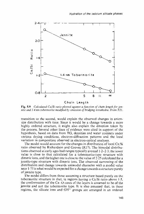
Hydration of the calcium silicate phases
2-4
2 - O -
o
o
if)
ou
1-2
O-8
r r
Jenni te
1.4 nm To bermor i te
8 II oo
Chain LengthFig. 5.9 Calculated Ca/Si ratio plotted against a function of chain length for jen-nite and 1-4 nm tobermorite modified by omission of bridging tetrahedra. From T21.
transition to the second, would explain the observed changes in anion-size distribution with time. Since it would be a change towards a morehighly ordered structure, it might also explain the direction taken bythe process. Several other lines of evidence were cited in support of thehypothesis, based on data from TG, densities and water contents undervarious drying conditions, electron-diffraction patterns and the localvariation in composition observed in electron-optical analyses.
The model would account for the changes in distribution of local Ca/Siratio observed by Richardson and Groves (R17). The bimodal distribu-tions observed at early ages had ranges typically around 1-2—2-3; the lowervalue is close to that calculated for a tobermorite-type structure withdimeric ions, and the higher one is close to the value of 2-25 calculated for ajenriite-type structure with dimeric ions. The observed narrowing of thedistribution and change towards unimodal character with a modal valuenear 1-75 is what would be expected for a change towards a structure purelyof jennite type.
The model differs from those assuming a structure based purely on thetobermorite structure in that, in regions having a Ca/Si ratio above 1-5,the conformation of the Ca-O cores of the layers is assumed to be of thejennite and not the tobermorite type. It is also assumed that, in theseregions, the silicate ions and OH~ groups are arranged in an ordered
143

Cement chemistry
way, as in jennite. A particular assumption was made concerning thecontent of Si-OH; this appears to give the best agreement with the data,but is not an essential feature of the model.
5.6.4 Other models for the C-S-H of calcium silicate andcement pastes
The mixed tobermorite-jennite model described above takes account oflocal variability in composition and structure. The results of Hendersonand Bailey (H30) and of Viehland et al. (V4) suggest that it may alsobe necessary to take into account local variability in crystallinity. Thepossibility of transitional structures intermediate between those of thecalcium silicate hydrate and calcium hydroxide may also need to beconsidered.
Some other models for the structure of C-S-H gel that have been prop-osed appear incompatible with the evidence. They include an identificationwith natural tobermorite, based on IR and extraction results (S48), oneassuming a close relation to the CH structure, with incorporation of mono-meric silicate ions (G41), and, as noted in Section 5.5.2, one assumingthree-dimensional anionic clusters (C28).
SiO2
SHv
NOT TO
SCALE
C35
H 2 O CaO
Fig. 5.10 The system CaO-SiO2-H2O at ordinary temperatures (schematic).From T27.
144

Hydration of the calcium silicate phases
5.7 Equilibria5.7.1 Solubility relationsEquilibria in the CaO-SiO2-H2O system at ordinary temperatures havebeen widely studied for the light they may cast on cement hydration and onleaching of concrete by ground waters. Steinour (S59,S60) reviewed earlywork and Jennings (J16) discussed later studies. If C-S-H(I) is placed inwater or CH solutions, its Ca/Si ratio changes until equilibrium is reached.Except at low CaO concentrations, the SiO2 concentrations in solution arevery low, so that transfer between solid and solution is almost entirelyof CaO. The data may be plotted schematically on a triangular diagram(Fig. 5.10), but because of the low concentrations it is more useful toemploy separate plots of the Ca/Si ratio of the solid or CSio2 against CCao(Figs 5.11 and 5.12).
In most of the investigations, the solid starting materials were either CHand hydrous silica, or C-S-H prepared either from those materials or bymixing solutions of sodium silicate and a soluble calcium salt, followed bywashing to remove the soluble product. In some, anhydrous calciumsilicates were used. The various sets of data represented by Figs 5.11 and5.12 show considerable divergencies; a few studies suggested the existenceof a step in the curve of Fig. 5.11 at Ca/Si« 1 • 1 (S59). With the importantexceptions of some of the data obtained using C3S or C2S, none of thesedifferences is clearly related to ones in starting material. They may beassociated with differences in structure; Grutzeck et al. (G51) found asimilar step in the related curve of Ca/Si ratio against pH, and concludedthat it represented the change from a tobermorite-type structure with longchains to a jennite-type structure containing shorter chains and dimericsilicate groups (Section 5.5). XRD powder evidence shows that the centralpart of the curve in Fig. 5.11 (CCao~2 to 22moll"1) and curve A of
so
lid
c
Ca/
Si
1-6
1-2
0-8
04
n
-
-
- -
i i i i i i i i i i i
4 8 12CaO in solution
16 20(mmole M
24
Fig. 5.11 Metastable equilibrium curve relating the Ca/Si ratios of C-S-Hpreparations to the analytical concentration of CaO in the solution, selected astypical from the results of many investigations. After S60.
145

Cement chemistry
i
oE3
'ION
r—
a:i—
z1 1 1L J
o
SiO
;
4000
2000
1000
400
200
100
40
20
10
4
2
1
0-4
0-2
0-10 5 10 15 20 25 30
CaO CONCENTRATION (mmot I"1)
Fig. 5.12 Concentration data for C-S-H based on the results of many investi-gations; for explanation of curves, see text. Broken lines give an indication of thescatter of the data. After J16.
Fig. 5.12 represent the solubilities of C-S-H(I) preparations and thatthere are invariant points for hydrous silica, C-S-H(I) with Ca/Si^0-8and solution with CCao ~ 1 mmol I"1 and CSio2 ~ 2 mmol I"1, and for CH,C-S-H(I) with Ca /S i«14 and solution with CC ao~22mmoll- 1 andCSio2- 1 ^moU'1 (J16,S60,T22). Figure 5.12 includes metastable solubi-lity curves for hydrous silica and CH.
Jennings (J16) noted that observed points on plots of CSio2 vs. CCaotended to fall on one or other of two curves, with relatively few in between(Fig. 5.12). Of those that fell between, some were obtained using (3-C2Sand others were suspect from carbonation or for other reasons. Thosefalling on the upper curve, B, had all been obtained by reaction of C3Swith water for periods not exceeding a few days; probably in all cases,unreacted C3S was present. Some of the experiments using C3S, and all ofthose using other starting materials other than /?-C2S, gave points lying on
146

Hydration of the calcium silicate phases
the lower curve, A. Of the experiments using C3S that gave points on curveA, some were of durations of 4 h or less (B56), but most appear to havebeen of long duration, and in at least one case, points lying on curve Awere obtained only if no unreacted C3S remained (T22).
Curve A is clearly the solubility curve of C-S-H(I); scatter at the CaO-rich end may arise because a given Ca/Si ratio can be associated with morethan one structural arrangement. However, any form of C-S-H that isstructurally derived from 1 -4 nm tobermorite or jennite or, perhaps morewidely, that is based on Ca-O sheets, probably has a solubility lying on orclose to this curve. There are no solubility data for C-S-H(II), l-4nmtobermorite or jennite, but one might expect the curves for the crystallinephases to lie below the relevant parts of curve A, and that of C-S-H(II) tolie near or slightly below the high CaO portion of that same curve.
Curve B is most unlikely to represent the metastable solubility ofanhydrous C3S; thermodynamic calculations (S61) indicate that such acurve would be very much higher, as would be expected from the highreactivity. Jennings (J16,J17) and Gartner and Jennings (G52) consideredit to be the metastable solubility curve of a product formed as a layer onthe C3S surface. Thermodynamic calculations based on this assumptionindicated Ca/Si ratios of 11 at low and 1-65 at high CaO concentrations;these values are broadly compatible with ESCA evidence (Section 5.8.2).Barret and Bertrandie (B60,B61) considered that curve B was not a solu-bility curve, but represented a quasisteady state in which the concentra-tions were such as to equalize the rate of dissolution of a hydroxylatedsurface layer on the C3S and the rate of precipitation of C-S-H. Bothviews associate the curve, though in different ways, with the presenceof an altered surface layer on the C3S that is metastable relative to theC-S-H whose solubility is represented by curve A. Experiments using/3-C2S give compositions lying on a curve between curves A and B(B60,G53) and which may similarly be associated with an altered surfacelayer on the /3-C2S.
There are few data on the concentrations of CaO and SiO2 in the poresolutions of C3S pastes (w/s < 10), as opposed to suspensions, and thosethat exist are conflicting as regards CSio2 (B56,O12). The values of CCaoafter long times (e.g. 27mmoll~1; O12) appear to be significantly abovethe solubility of CH; this has been attributed to incorporation of SiO2 inthe CH (W23), but might also be due to the small crystal size of some ofthis phase.
5.7.2 Species in solutionBarby et al. (B62) summarized data for silicate species in alkali silicatesolutions. Monosilicic acid, H4SiO4, has pKal =9-46, pKa2 = 12-56, andpKa3 probably about 15. Monomeric species are overwhelmingly pre-dominant at CSio2 below about 2 mmol I"1 at pH values up to 9, and up tohigher concentrations at higher pH. The solubility product of CH, interms of activities, is 91 x 10"6mol3 T3 at 25°C (G42), and the stabilityconstant of the complex CaOH+ is 20moH~1 (S62). Undissociated CH is
147

Cement chemistry
not a significant species in saturated CH solution (G52). In saturated CHat 25°C, the activities of Ca2+ and CaOH+ are roughly equal, and the pHis 1245. The stability constants of CaH2SiO<| and CaH3SiO^ are reportedto be 1240moir1 and 2.5moll"1 respectively (S62), but some doubt hasbeen cast on these values by the results of thermodynamic calculationsusing them (G52).
Using the equilibrium constants given above, together with standardexpressions to calculate ionic strength and activity coefficients, one maycalculate the species concentrations and species activities in a system ofgiven bulk composition. For Ccao^^S-Ommoll"1, CSio2 = 200fim I"1,and assuming that calcium silicate complexes are not present, the speciesconcentrations ( inmoir 1 ) are Ca2+, 1-90 x 10~2; CaOH+, 8-98 x 10"3;OH", 4-70 x 10-2; H4SiO4, 4-19 x 10"9; HsSiOj, 6-82 x 10~6; H.SiO2-,1-30 x 10~5; HSiO3-, 1-46 x 10~7 (G52). The activity of OH" is 3-78 xlO^moll"1 ; this corresponds to a pH of 12-58. If the complexesCaH2SiO4 and CaH3SiO4
f are assumed to occur, with stability constantsof 2000 and 20moll"1, respectively, the concentrations of the SiO2-containing species become (moll"1): CaH3SiOj, 2-01 x 10"7; CaH2SiO^1-61 x 10~5; H4SiO4, 7-75 x 10"10; H3Si04 , 1-26 x 10~6; H2Si02~, 2-41 x10~6; HSiO^, 2-70 x 10~8, the neutral complex CaH2SiO5 thus being theprincipal SiO2-containing species. The concentrations of Ca2+, CaOH+
and OH~ are not significantly affected.
5.7.3 Thermochemistry and thermodynamicsUsing a heat of solution method, Lerch and Bogue (L24) found theenthalpies of hydration of C3S and /3-C2S in pastes to be - l ^ k J m o l " 1
and —45 kJ mol"1 respectively. Similar values have been reported by otherinvestigators, e.g. -HSkJmol" 1 and -45kJmol~1 by Brisi (B63) and- m k J m o r 1 and -46kJmol~1 by Fujii and Kondo (F22), who recal-culated data obtained by Brunauer et al. (B64) for dried products.Brunauer et al. noted that, if the hydration products of C3S and /?-C2Swere identical apart from the quantities of CH formed, the enthalpy ofhydration of C3S should equal the sum of the enthalpies of hydrationof /3-C2S, hydration of CaO (AH29s= -65-2kJmor 1 ; W10), and reac-tion of /3-C2S and CaO to give C3S (AH29S= -13-4kJmor 1 ; W10). Forthe moist material, this sum is -124kJmol"1 , which is near the observedvalue.
Fujii and Kondo (F22) calculated the thermodynamic properties ofC-S-H, using solubility data and properties of l-4nm tobermorite andCH given by Babushkin et al. (B65). The C-S-H was treated as equiva-lent to a solid solution of these two compounds. For the composi-tion 17CaO-SiO2-2-617H2O, they found A//° = 2890kJmor1 , AG° =-2630 kJ mol"1 and S° = 200 J mol"1 K"1. They showed that these valueswere consistent with data for the enthalpies of hydration of C3S and/3-C2S. The free energy of formation of C-S-H from l-4nm tobermoriteand CH was shown to become increasingly negative with increasing Ca/Siratio, but to tend towards a limit at ratios approaching 20; this isconsistent with the observed upper value of this quantity.
148
Hydration of the calcium silicate phases
Glasser et al. (G54) calculated the activities of the principal ionic speciesin solutions in equilibrium with C-S-H of various Ca/Si ratios, andsolubility products defined in terms of those species. Using values ofAG°f for the ionic species (B65), values of AG2 for the solids were thencalculated. The results depended somewhat on the set of solubility dataused, but were broadly similar to those obtained by Fujii and Kondo(F22). Using one set of data, values ranged from -1720kJmol~1 atCa/Si = 0-93 to -2350 kJ mol"l at Ca/Si = 1-63, referred to formulae con-taining one silicon atom in each case.
The Gibbs-Duhem equation has been used to calculate Ca/Si ratios ofsolids from the CaO and SiO2 concentrations in solutions with whichthose solids are in equilibrium (F23,G52). Gartner and Jennings (G52)showed that, at the low concentrations involved, this equation reduces tothe approximate form (Ca/Si)soiid = -d//s/d/ic, where /xs and /ic are thechemical potentials of SiO2 and CaO respectively. The calculations werecarried out for curve B and three variants of curve A on Fig. 5.12. Forpoints along each curve, activities of the ionic species in solution werecalculated, and from these, values of /is and \ic\ these were plotted againsteach other to give curves on a chemical potential phase diagram. From theslopes at points along these curves, the Ca/Si ratios of the solids wereobtained. For one variant of curve A, the calculated Ca/Si ratios atCcaO = 3mmoll~1 and 144mmoll"1 were 10 and 1-45 respectively. Thesevalues agree well with typical experimental results shown on Fig. 5.11.For curve B, the calculated Ca/Si ratios were 11 at Smmoll"1, 1-65 atHmmoll"1 and 1-65 at 22mmoll~1.
5.7.4 Effects of alkalis and of gypsumBrown (B66) reviewed studies on the Na2O-CaO-SiO2-H2O system at25°C, based largely on the results of Kalousek (K20) and Macphee et al.(M61). The crystallization surfaces of the solid phases on the quaternarydiagram were partiallyor completely defined. The quaternary solid phasescomprised a sodium-substituted form of C-S-H, which was termedC-'N'-S-H, a calcium-substituted sodium silicate hydrate and a com-pound of composition 0-25Na2O • CaO • SiO2 • 3H2O. Brown noted thatthe concentrations in the pore solutions of cement pastes tended to fallalong the curve bounding the surfaces for CH and C-'N'-S-H, but thatthere was a problem in reconciling the alkali content of the C-S-H withKalousek's equilibrium data. In further work, Brown (B67) modelled thechanges in solution composition during C3S hydration. A small contentof Na2O in the C3S greatly increased the concentrations of OH~ anddecreased those of Ca2+. In the presence of a limited amount of gypsum,the concentrations of Ca2+ and SO^" were significant so long as anygypsum remained but decreased due to uptake of SO^" by the C-S-H,leaving a solution that was essentially one of NaOH. This behaviourresembles that found with cement pastes (Section 7.5.1). Other studiesbearing on equilibria in the CaO-SiO2-H2O system in the presence ofalkalis have been reported (B68,S63).
149

Cement chemistry
5.8 Kinetics and mechanisms5.8.1 C3S; experimental dataFigure 5.13 shows the general form of the curve relating the fraction ofC3S consumed (a) to time in a paste of w/s^0-5 at about 25°C and withmoist curing. Such curves have been determined using QXDA for un-reacted C3S (e.g. K21,O11), though the precision is low for values ofa below about 0-1. At low values of a, other methods are available, such asconduction calorimetry (e.g. P22), aqueous phase analyses (e.g. B69) ordeterminations of CH content or of non-evaporable water. At very earlyages, it may be necessary to allow for the fact that the property deter-mined depends on the nature of the hydration products, e.g. precipitationof C-S-H begins before that of CH.
The rate, as followed from that of heat evolution (Fig. 5.14), passesthrough an initial maximum, decreases to a minimum during a so-calledinduction period, passes through a second maximum and then graduallydeclines. Kondo and Ueda (K21) described five periods of reaction, viz.:(1) the initial reaction, (2) the induction period, (3) the acceleratoryperiod, in which the main reaction first begins to occur rapidly, (4) thedeceleratory period and (5) a period of slow, continued reaction.Periods 1 and 2 correspond to the early stage of reaction as definedfrom microstructural studies (Section 5.3.2), periods 3 and 4 to the
( days )
2 . Time ( hours )Fig. 5.13 General form of curves relating the fraction ofC3S consumed to time in apaste. AB: initial reaction. BC: induction period. CD: acceleratory period. DE:deceleratory period and continuing slow reaction. From T27.
150

Hydration of the calcium silicate phases
8 16Time (hours)
24
Fig. 5.14 Typical calorimetric curve relating the rate of heat liberation to time fora C3S paste. After B70.
middle stage, and period 5 to the late stage. Setting takes place duringthe acceleratory period.
Many investigators have followed the changes in CCao and CSio2 or[OH~] with time in the course of the reaction of water with C3S or /3-C2Sin suspensions (e.g. B56,B69,G55; Fig. 5.15). The curves for CCao
o r
[OH~] typically show a steep rise during the initial reaction and a moregradual one of uniform slope during the induction period. Significant
1 2 3T i m e ( h o u r s )
Fig. 5.15 Plots of the analytical concentrations of CaO and SiO2 against time fora C3Spaste (C3S 352-5m2kg~\ w/s 0-7, 24°C). After B56.
151

Cement chemistry
precipitation of CH begins just before the maximum concentrations arereached, and is rapid when they decrease, during the acceleratory period(W23). Some of the curves reported in the literature show a plateau in theearly part of the induction period, followed by a rise (e.g. B60). In themost marked cases of this behaviour, the maximum is unusually high(^Ommoll" 1) and unusually delayed (24-36 h; e.g. F24). As noted inSection 5.7.1, the final values reported for pastes tend to be well above thesolubility of CH. The SiO2 concentration passes through a maximum inthe order of lmmoll"1 during the initial reaction. Brown et al. (B56)found the solution compositions to lie exclusively on curve A of Fig. 5.12,but other workers have found the paths followed by the concentrations tocross curve A, passing through maxima near (G55) or beyond (B60,B61)curve B and then falling back to curve A.
At early ages, da/dt increases markedly with w/s ratid above 0-7 (B56).Moderate variations in specific surface area have little effeij: on the length ofthe induction period, but with finer grinding, da/dt during "the acceleratoryperiod increases (B56,K21,O13). The rate of reaction increases withtemperature up to the end of the the acceleratory period, but is much lessaffected thereafter (K19), suggesting a change from chemical to diffusioncontrol. Introduction of defects into the C3S shortens the induction period(F24,M62,O13).
The results of experiments at high w/s ratios have been interpretedassuming superficial hydroxylation of the C3S followed by congruentdissolution and subsequent precipitation (B60,B69). Damidot and co-workers (D22-D24) followed the hydration of C3S using a technique thatallowed simultaneous monitoring of the heat flow and electrical con-ductivity. The use of high w/s ratios also greatly facilitated the study of theearlier stages of the reaction, and made it possible to distinguish endo-thermic blips on the generally exothermic calorimetric curve, attributableto the onset of precipitation first of C-S-H and later of CH. From theirresults, the authors concluded that the initial process was one of congruentdissolution of C3S. When the limiting supersaturation of C-S-H had beenreached, this phase began to precipitate, initially by homogeneousnucleation and later by heterogeneous nucleation and growth on ahydroxylated C3S surface. During this stage, CCao and the Ca/Si ratio ofthe C-S-H increased; when the limiting supersaturation of CH had beenreached, that phase also precipitated. Three distinct forms of C-S-H wereconsidered to form over different ranges of CCao (Section 5.5.4).
Reaction in pastes must also occur at least partly by dissolution andprecipitation, since much of the product is deposited at a distance fromthe starting material, and because both CCao and CSio2 pass throughmaxima. Topochemical mechanisms, defined as ones in which thematerial does not pass through a true solution phase, may also occur,especially in the late stage of reaction (T28).
The kinetics up to the middle of the acceleratory period are discussedin the following sections. Those of the later stages have been morethoroughly studied with cement (Section 7.7) and only some aspects areconsidered here.
152

Hydration of the calcium silicate phases
5.8.2 C3S: the initial reactionTwo ESCA studies of the hydration of C3S pastes or compacts showed aninitial surface Ca/Si ratio of 30, which within the first minute fell sharplyand then increased again; it then fell more slowly, reaching a value of1-5-20 in 15-30min (M48,R24,T29). Allowing for the fact that the regionanalysed will include unreacted C3S until the layer of hydration product issufficiently thick and continuous, these results may be interpreted in termsof the formation of an initial hydrate of low Ca/Si ratio, which rapidlyincreases (R24). Another study (B71), in contrast, showed an unreactedC3S sample to have a low surface Ca/Si ratio. ESCA results also indicate achange in the environment of the silicon atoms at the end of the inductionperiod, possibly associated with the formation of dimeric silicate ions(R24). Secondary-ion mass spectrometry (SIMS) is a possible alternativemethod for studying surface compositions, but has not yet giveninformation on that of the hydrated material (G56). Electron diffractionshows that an amorphous surface layer can be produced by grinding(K21,U11); this may explain some of the reported differences in behaviourbetween apparently similar specimens.
Calculations of a from concentrations in the bulk solution indicatevalues of around 0-3% at the start of the induction period (B56,B69).These are likely to be minimum estimates, because they assume that noCH is formed; in reality, small amounts may be, on account of concen-tration gradients, which will themselves introduce an error in the samedirection. Reported values of a, summarized by Odler and Dorr (Oil),range from 0 1 % to an improbable 8%. Their own estimate of 1-2% issupported by subsequent evidence from cross-polarization 29Si NMR(R19). Assuming a specific surface area of 300 m2 kg"1, a value of 1%corresponds to a mean depth of attack of about 10 nm.
5.8.3 C3S: the induction periodThe causes of the induction period and of its termination have been thesubject of much debate. Hypotheses have been reviewed in a collabora-tive paper (T27). The main ones are as follows.
(1) The product of the initial reaction forms a protective layer on theC3S particles; the induction period ends when this is destroyed orrendered more permeable by ageing or phase transformation(B72,J16,S64).
(2) The product of the initial reaction forms a semipermeablemembrane which encloses an inner solution and is destroyed byosmotic bursting (D25).
(3) The rate of reaction in the induction and acceleratory periods iscontrolled by nucleation and growth of the C-S-H formed inthe main reaction, the induction period ending when growthbegins (B69,F24,O14,S65).
(4) The induction period occurs because the CH nuclei are poisonedby SiO2 and cannot grow, and ends when the level of super-saturation is sufficient to overcome this effect (G57,T30,W23).
153

Cement chemistry
The induction period is shortened by adding prehydrated C3S (O14), butadditions of lime or CH, including that formed from C3S, are variouslyreported to be ineffective (B73,O14) or to lengthen it, though shorteningit with cement (U12). In cement mixes, additions of flyash or some otherfinely divided materials accelerate hydration after the first day, appar-ently by acting as nucleation sites for C-S-H (Section 9.3.3). Additionsof reactive silica markedly accelerate hydration (S64). Most of thisevidence supports hypothesis 3 and tells against hypothesis 4. Hypothesis3 does not exclude hypothesis 1, as the breakdown of a protective layercould be associated with formation of a new product.
The recent microstructural evidence (Section 5.3.2) gives no indicationthat a membrane or other product distinct from that formed later isformed during the initial reaction in C3S pastes, though a gelatinouscoating is formed in cement pastes, which show an induction periodsimilar to that observed with C3S (Section 7.5.1). For C3S pastes, thisevidence excludes hypothesis 2, and gives no positive support tohypothesis 1. It does not exclude the formation of an altered layer onthe C3S surface, no more than a few nanometres thick. Tadros et al. (T30)postulated the formation of an SiO2-rich layer with chemisorbed Ca2+,and Barret et al. (B69) that of a superficially hydroxylated C3S, formed byprotonation of the O2~ and SiO^" ions, balanced by loss of Ca2+.
The calculated solubility of C3S is about 1 molal (S61). In the absenceof an altered or protective layer, the observed low rate of reaction duringthe induction period could be explained only if the concentrations closeto the C3S surface were of this order of magnitude. It is doubtful whetherthe very high concentration gradients that this implies could exist(G53,J16).
The balance of the evidence favours a combination of hypotheses1 and 3. The following model is essentially that of Gartner and Gaidis(G53), but has features in common with those of Barret and Bertrandie(B60) and of Grutzeck and Ramachandran (G55).
(1) In the initial reaction, C3S dissolves and a material is deposited,which will be termed Product B. The dissolving C3S probably hasa hydroxylated surface, as proposed by Barret et al. (B69). Undertypical paste conditions, Product B forms an overlying surfacelayer about 1 nm in average thickness, though it is likely to benon-uniform and thicker around active sites. It may be capable ofexistence only on a C3S surface and similar to a passive layer on ametal. Within 30 s the C3S is almost isolated from the solution,and an unstable equilibrium, represented by curve B of Fig. 5.12,is established between the solution and Product B.
(2) Product B is unstable with respect to the material represented bycurve A of Fig. 5.12, for which we shall reserve the term C-S-H.During the early part of the induction period, C-S-H nucleatesand begins to grow. This implies dissolution of Product B, andincreased access of solution to the C3S, which thus dissolvesmore rapidly. The rate of reaction in this stage is controlled
154

Hydration of the calcium silicate phases
by the growth of C-S-H, the rate of which increases with theamount already formed.
The amount of Product B at any given stage in the reaction must dependon the relative rates of its formation and dissolution. It may or may notdisappear completely when the latter is sufficiently high. The NMRevidence (Section 5.5.3) indicates that the hydrated material formed up tothe end of the induction period contains only monomeric silicate ions andthat the latter persist alongside larger ions when the latter are formed.This suggests that the silicate ions are monomeric both in Product Band in C-S-H in the early stages of formation of the latter product. TheCa/Si ratio of Product B is possibly about 1 initially, increasing to about1-7 as equilibrium with CH is approached.
5.8.4 The main reaction (C3S and (3-C2S)From the kinetic standpoint, there is probably no distinction between theinduction period and the early part of the acceleratory period; indeed, asGartner and Gaidis (G53) noted, there is strictly no induction period inthe absence of retarding admixtures. Throughout both stages, growth ofC-S-H proceeds at an increasing rate, which is reflected in increasinglyrapid dissolution of the C3S. The Ca2+ and OH~ concentrations in thebulk solution increase steadily, and when a sufficient degree of super-saturation has been reached, CH begins to precipitate in quantity, causingthese concentrations to fall. Its formation is not normally rate-deter-mining, but could become so in the presence of admixtures that retard itsgrowth. The kinetic data for this stage can be fitted by Avrami-type equa-tions, but the assumptions underlying the latter (formation of a productwithin an initially homogeneous material) do not correspond to thesituation existing in the hydration of C3S or cement.
The smaller grains of C3S probably react completely, by dissolution andprecipitation, during the acceleratory period. In the final, slow periods ofhydration, the remaining grains of C3S, which are relatively large, aregradually replaced by C-S-H through the inward movement of an inter-face. It is difficult to believe that such a process occurs by dissolution intoa true liquid phase, followed by precipitation. Following earlier studies(F25,K21,K22,M53), Taylor (T28) suggested that a topochemical reac-tion may occur with both C3S and /3-C2S. Comparison of the numbers ofatoms of each element in the initial and product phases shows that toconvert either C3S or /?-C2S into C-S-H, relatively little O2~ must begained or lost; much of the Ca2+ and smaller proportions of the Si4+ mustbe lost, and equivalent amounts of H + gained (Table 5.6). At the inter-face, a narrow zone could exist, in which the necessary atomic rearrange-ments take place. It is not necessary to postulate any migration of watermolecules through the inner product; instead, Ca2+ and Si4+ move out-wards, and H + inwards. At the surface, the Ca2+ and Si4+ enter thesolution, and ultimately precipitate, along with the OH~ ions releasedfrom the H2O molecules, as CH and outer product C-S-H. Migration ofsilicon was suggested as the probable rate-determining step; however, at
155

Cement chemistry
Table 5.6 Numbers of atoms in 1000/No ml
Phase
C3SP-c2sC-S-H (90% RH)
Density (kg m 3)
312033261900
Ca
41038-6144
Si
13-719-38-2
H
660
O
68-311-263-9
Slightly modified from T28; C-S^H composition assumed C1.75SH4.0-
low w/s ratios, reaction stops because there is no more space in which theouter product can be formed, and in this case, control presumably shiftsto some process related to deposition of outer product. Barret (B74)discussed topochemical mechanisms and their relation to dissolution-precipitation processes.
5.8.5 Early hydration of (3-C2SThe kinetics and mechanism of /3-C2S hydration are similar to those forC3S, apart from the much lower rate of reaction (F15,F26,M62,O15,T31),and as noted earlier, the products are similar apart from the much smallercontent of CH. Preparations appear to be more variable in reactivity thanthose of C3S; this is partly attributable to differing stabilizers (F27), butcould also be due to differing amounts or natures of phases in intergranularspaces or exsolution lamellae. Preparations made at low temperatures areespecially reactive (F26). Because of the low rate of heat evolution,conduction calorimetry is difficult, but shows the existence of an inductionperiod similar to that found with C3S (M62), which is also indicated byQXDA (O15). ESCA, SEM and solution studies show that behaviourduring the early period is similar in principle to that of C3S (M63). TheESCA data show that the connectivity of the silicate tetrahedra increaseswithin 24 h at 50°C; this behaviour resembles that of C3S at the end of theinduction period. They show the approximate depth of the hydrated layerto be 5nm after 15 s, and 15nm after 6h at 25°C. The rate of reaction isincreased in presence of C3S (O15,T31).
156

6 Hydrated aluminate, ferrite andsulfate phases
6.1 AFm phases6.1.1 Compositional and structural principlesAFm (Al2O3-Fe2O3-mono) phases are formed when the ions theycontain are brought together in appropriate concentrations in aqueoussystems at room temperature. Some can also be formed hydrothermally,i.e. in the presence of water under pressure above 100°C. They are amongthe hydration products of Portland cements. Under favourable condi-tions, they form platey, hexagonal crystals with excellent (0001) cleav-age. Some of the AFm phase formed in Portland cement pastes is of thistype, but much is poorly crystalline and intimately mixed with C-S-H.AFm phases have the general formula [Ca2(Al,Fe)(OH)6] • X • xH2O,where X denotes one formula unit of a singly charged anion, or half aformula unit of a doubly charged anion. The term 'mono' relates tothe single formula unit of CaX2 in another way of writing the formula,viz. C3(A,F).CaX2.jH2O [or C4(A,F)X2.yH2O], where y = 2(x + 3).Many different anions can serve as X, of which the most important forPortland cement hydration are OH~, SO4"" and CO2~. A crystal maycontain more than one species of X anion. AFm-type phases can also beprepared in which other tripositive cations, such as Cr3+, replace the Al3+
or Fe3+.AFm phases have layer structures derived from that of CH by the
ordered replacement of one Ca2+ ion in three by Al3+ or Fe3+ (Fig. 6.1;A10-A12). The principal layers thus defined alternate with interlayerscontaining the X anions, which balance the charge, and H2O molecules.The replacement of Ca2+ by the smaller Al3+ or Fe3+ ions distorts thestructure of the principal layer, alternate Ca2+ ions moving in oppositedirections from its central plane. This allows each to coordinate theoxygen atom of an interlayer H2O molecule in addition to its six OH~ions. The principal layer, together with the H2O molecules thus bondedto the Ca2+ ions, has the composition [Ca2(Al,Fe)(OH)6-2H2O]+. In thesimpler AFm structures, these units are stacked in such a way as toproduce octahedral cavities surrounded by three H2O molecules from
157

Cement chemistry
OH
Fig. 6.1 Structure of a single principal layer of composition [Ca2Al(OH)6]+ in an
AFm phase, in ab-projection. Distances of calcium, aluminium and oxygen atomsabove or below the central plane of the layer are in pm. Hydrogen atoms are notshown. Large circles illustrate the distortion of the CaO6 octahedra, which allowsthe coordination of each calcium atom to rise to 7 through the addition of a watermolecule (not shown) directly above or below it in this projection.
each of the adjacent layers. These cavities may contain X anions, H2Omolecules, or both. In C3A.CaCl2- 10H2O (or [Ca2Al(OH)6• 2H2O]C1),each cavity contains a Cl~ ion. In C3A«CaSO4- 12H2O, one half containSO4"- anions and the remainder contain two H2O molecules. In C4AH13,all contain one OH~ anion and one H2O molecule.
The unit cells of all AFm phases are based on hexagonal structuralelements with a = 0-57-0-59 nm. These values are somewhat less than y/3times that of CH. The layer thickness c' depends on the nature of the Xanion and the amount of interlayer water, which can be varied bystepwise dehydration from the highest hydration state. AFm phases existin which a complete, additional layer of H2O molecules is presentbetween the principal layers. There is no restriction on the separationbetween adjacent layers; this allows large anions, and also intercalatedneutral molecules (D26,D27), to be present in interlayer sites. Many AFmphases readily undergo changes in water content and anion exchange(D27,F28), the latter including that of C O ^ for OH". Due care musttherefore often be taken to exclude CO2, and where necessary also tocontrol the humidity.
Complex sequences of stacking the layers, or ordered patterns of fillingof the cavities where their contents are not all the same, lead to unit cellsthat are larger or of lower symmetry than the structural element. SomeAFm phases show polytypism, arising from differences in layer stacking.
158

Hydrated aluminate, ferrite and sulfate phases
6.1.2 The C4AHX, C4AC05Hx and C4ACHX phasesFischer and Kuzel (F29) summarized and extended earlier work on thesegroups of AFm phases, which are listed in Table 6.1. In the pure CaO-A12O3-H2O system, the phase in metastable equilibrium with solutions ofappropriate composition at temperatures up to at least 50°C is C4AH19,of which two polytypes (a\ and a2) are known. On decreasing the RH orincreasing the temperature, lower hydrates are reversibly formed, withdecrease in layer thickness; a decrease in RH to 81% is sufficient toproduce C4AH13 (R25). C4AH19 is structurally derived from C4AH13 bythe addition of an extra layer of H2O molecules. A high degree ofcrystallinity is needed to allow this extra layer to form (D28), and it isdoubtful whether it could occur in the material in a cement paste. InC4AHn, the contents of the octahedral cavities in the interlayers arereduced from (OH~ +H2O) to OH~, and in C4AH7, which is a poorlycrystalline material, the H2O molecules attached to the Ca2+ ions havealso been lost.
The layer thicknesses indicate that the CO3~ ions are oriented parallelto the layers in C4ACHn, and perpendicular to them in C4AC0.5Hi2. Inall these CO3~-containing phases, some octahedral cavities contain aCO3~ ion, and others varying combinations of H2p molecules and OH~ions. In the early literature, C4ACHn (or C3A • CC • Hn) was incorrectlyidentified as a C3A hydrate, and C4AQ) 5H12 as a polymorph of C4AH13.Both phases readily form on carbonation of the C4A hydrates.
Table 6.1 AFm phases of the C4AHX, C4AC05Hx and C4ACHX groups
Composition(F29)
C4AH19
C4AH13
C 4 AH n
Q A H 7
C 4 A C Q 5 H I 2
C4AC0.5H11.25C4ACo-5Hio5
C 4 A C Q - 5 H 6 . 5
C4ACHn
C4ACH8
C4ACH6
Dryingconditions
25°C, >88% RH25°C, 11-81% RH40°C, 25% RH25°C, anhydrous CaCl2
50-90°C25°C, P2O5
110-120°C22°C, >36% RH40°C, 25% RH35°C25°C, anhydrous CaCl2
80°C25°C, P2O5
105°C25°C, saturated CaCl2
95°C130°C
Ref.
R25R251R25JR251B75 JR251B75 JF29)R25JF29R25)F29 JR251F29 JF29F29F29
Layerthickness(nm) (F29)
1068
0-794
0-7^5KJ 1 J) J
0-56
0-8193
0-763
0-726
0-66
0-7560-720-66
Interlayer contents*
OH-
11
1
11
1
1
1/2
1/2
1/2
1/2
000
0
0
n\j
0
1/4
1/4
1/4
1/4
1/21/21/2
H2O
6
3
2
11/4
19/8
2
0
5/210
15 Per formula unit of Ca2Al(OH)+.
159

I 1 CD j_3
Tab
le 6
.2
Cry
stal
dat
a fo
r A
Fm
pha
ses
§• CD
Pha
se
Cry
stal
S
pace
gro
up
Uni
t ce
ll pa
ram
eter
s Z
D
x R
ef.
%sy
stem
f (k
g m
~3 )
^a
(nm
) b
(nm
) c
(nm
) A
ngle
ai-C
4A
H1
9 H
R
3co
rR3
c(?)
0-
577
- 64
08
7 =
120
° 3
1803
A
13a 2
-C4A
H1
9 H
P
63/m
orP
632
2 0-
577
- 2-
137
7=
12
0°
1 18
02
A13
C4A
H1
3 H
R
--
0-57
52
- 95
27
7 =
12
0°
6 20
46
F29
C4A
C0.
5H12
H
R
3c
orR
3c
0-57
70
- 4-
9159
7
=
120°
3
1984
F
29C
4A
CH
n T
P
I or
PI
0-57
81
0-57
44
0-78
55
J 1/
2 21
70
F29
C4A
SH
12
H
R3
0-57
6 -
2-67
9 7
=
120°
3/
2 20
14
A14
a-C
3A
-CaC
l 2-H
10
M
C2/
c or
Cc
0-99
8 0-
574
1-67
9 0
=11
0-2°
2
2065
K
23/3
-C3A
-CaC
l 2-H
10
H
R3c
or
R3c
0-
574
- 4-
688
7 =
120
° 3
2090
K
23C
3A
-CaC
l 2-H
6 H
R
3c o
r R
3c
0-57
29
- 4-
1233
7
=
120°
3
2080
K
24C
2AH
7.5*
M
C
2/c
orC
c 0-
993
0-57
4 4-
22
(3 =
97.
0°
8 19
43
S66
C2A
H5
H
R3c
0-
573
- 5
22
7 =
120
° 6
2042
S6
6C
2AS
H8
H
R3
orR
3 0-
5747
-
3-76
4 7
=
120°
3
1936
K
25
•For
C2A
H8,
only
the
stru
ctur
al e
lem
ent
(a =
0-5
74nm
, c=
107
nm,
Z =
1) a
nd X
-ray
den
sity
(19
50kg
m"3 )
are
know
n (S
66).
t H =
hex
agon
al o
r tri
gona
l; M
= m
onoc
linic
; T
= tr
iclin
ic.
ta =
92-6
1°, (
3 -
101-
96°,
7 =
120
09°.

Hydrated aluminate, ferrite and sulfate phases
Table 6.2 includes crystal data for C4AHX, C4AC0 sH* and C4ACHX
groups. Only data based on single-crystal studies are included. Solidsolutions in these groups of phases appear to be very limited, onlyC4AC0.5H12 showing some variation in layer thickness up to a maximumof about 0-825 nm associated with partial replacement of CO^" by 2OH~together with variations in H2O content (D28,F29). The limiting com-position is C4AC0 2sHx. More extensive solid solution may occur in thepoorly crystalline material formed in cement pastes.
6.1.3 The C4ASHX phasesTables 6.2 and 6.3 give data for these phases. C4ASH12 (or C3A • CS • Hi2)is variously known as monosulfate, monosulfoaluminate, or, in the earlyliterature, low-sulfate calcium sulfoaluminate. The water contents of thetwo highest hydrates are uncertain, values of 16 for the 0-95 nm hydrate(T32) and of 15 for the 103 nm hydrate (R25) having also been reported.An alternative formula with 18H2O (M64) for the 0-95 nm hydrateimplies an impossibly high density for the additional water.
C4ASH12 forms solid solutions in which the SO4~ is partly replaced byOH". The maximum replacement is 50% at 25°C, 33% at 45°C, 17% at60°C and nil at 80°C. The layer thickness c' decreases with increasingOH~ content, to a value of 0-879 nm at 50% replacement (P23). Earlyreports that a continuous solid solution series exists with C4AHX areincorrect. They were based on observations by light microscopy, whichwith layer structures of this type cannot distinguish between a true solidsolution, in which the components are mixed at or below a nanometrelevel within each layer, an oriented intergrowth consisting of blocks eachcontaining many layers of one or other component, or intermediatepossibilities, such as random interstratification of layers of differenttypes. Distinction can be made by XRD. C4ASH12 and C4ACHn appearto be immiscible, but C4AC0 5H12 can accommodate a limited amount ofsulfate (K26).
A compound of approximate composition QA0.9N0.5S1.1H15, knownas U-phase, was reported to form at high concentrations of Na2O, A12O3
and SO3 (D29). Three hydration states, with c' = 100, 0-93, and 0-81 nm,and 16, 12 and 8 moles of H2O, respectively, were described, and it wassuggested that the structure was derived from that of C4ASHX by theomission of some of the Al3+ ions, balanced by the inclusion of Na+,in addition to anions, in the interlayer. Several other investigationshave confirmed the existence of this phase (B76,L25,S67,W24). Sup-porting evidence that AFm phases can accommodate cations as well asanions in the interlayer is provided by the existence of a compound[Ca2Al(OH)6]K • (C1O4)2 • *H2O (D27).
6.1.4 Other AFm phases containing aluminiumThe range of anions that can occupy the X positions is very wide(A14,D27); even anions that form Ca salts of very low solubility, such asF~, can be introduced using special techniques. We shall consider onlythose most relevant to cement chemistry. Tables 6.2 and 6.3 include data.
161

Tab
le 6
.3
AF
m p
hase
s
Com
posi
tion
QA
SH
16*
C4A
SH
, 4*
C4A
SH
12
C4A
SH
]oC
4AS
H8
C3A
-CaC
l 2-H
10(a
)C
3A
.CaC
l 2.H
10(/
?)C
3A
-CaC
l 2-H
6
C2A
H8
C2A
H7.
5
C2A
H5
C2A
SH
8
C2A
SH
4
wit
h [C
a 2A
l(O
H) 6
]+
prin
cipa
l la
yers
Dry
ing
cond
itio
ns
<1
0°C
at
100%
RH
>1
0°C
at
100%
RH
>10
°C a
t 2
0-9
5%
RH
>1
0°C
at
<2
0%
RH
30°-
50°C
ove
r P
2O
5
<28
°C a
t 35
% R
H>
28°C
at
35%
RH
120-
200°
C
<26
°C a
t 4
5%
RH
>26
°C a
t 4
5%
RH
Roo
m t
emp,
ove
r P
2O
5
Roo
m t
emp,
at
37%
RH
>13
5°C
and
inte
rlay
er s
ulfa
te,
chlo
ride
,
Lay
er t
hick
ness
(nm
)
103
0-95
0-89
30-
815
0-79
5
0-78
80-
781
0-68
7
107
104
0-87
1-25
511
2
alum
inat
e or
alu
min
osil
icat
e an
ions
Inte
rlay
er
l/2SO
f1/
2SO
2-1/
2SO
2-1/
2SO
2-1/
2SO
2-
lCl"
ici-
ici-
1A1(
OH
)4^
1A1(
OH
)41A
1(O
H)4
lAlS
iO8H
8-!A
lSiO
5H2-
cont
ents
f
5H2O
4H2O
3H2O
2H2O
1H2O
2H2O
2H2O
: 3H
2O5/
2H2O
1H2O
Ref
.
D28
D28
D28
D28
D28
K23
K23
K24
S66
S66
S66
K25
K25
Cement chemistry
* W
ater
con
tent
s un
cert
ain;
see
tex
t.fP
er f
orm
ula
unit
of
Ca[
Al(
OH
) 6]+
.I
Al
is 4
coo
rdin
ated
in
C2A
H7.
5 (R
26,S
66)
and
poss
ibly
6-c
oord
inat
ed i
n C
2A
H8
(G58
).

Hydrated aluminate, ferrite and sulfate phases
C3A.CaCl2-10H2O or [Ca2Al(OH)6]Cl• 2H2O (Friedel's salt) can beformed in concrete exposed to chloride solutions. Two polytypes areknown; f3 is the higher temperature form, produced reversibly from a at28°C. C3A-CaCl2- 10H2O does not form solid solutions with the sulfateAFm phases, but an ordered compound C6A2 • CS • CaCl2 • 24H2O exists,in which interlayers containing Cl~ probably alternate with ones con-taining SO2" (K23).
The C2A hydrates are AFm phases with aluminium-containing speciesin the interlayer. The hydrate formed in metastable equilibrium withaqueous solution at 18°C is C2AH8. Scheller and Kuzel (S66) found that,contrary to some earlier opinions, C2AH8 shows neither polymorphismnor polytypism, but that below 45% RH at 26°C it is converted intoC2AH75 . The transition temperature depends on the RH. An X-raystructure determination on the lower hydrate, C2AH5, showed that thishad the constitution [Ca2Al(OH)6][Al(OH)4], the interlayer Al and someof the interlayer OH groups being statistically distributed. Because ofpoor crystallinity, it was not possible to obtain such detailed informationabout the higher hydrates, but some evidence was obtained for a similarconstitution, with H2O molecules added, in C2AH75 . A study using 27A1NMR and EXAFS (extended X-ray absorption fine structure spectro-scopy) confirmed this conclusion (R26). In contrast, an earlier study ofC2AH8 (or C2AH75?) using 27A1 NMR showed that all the Al wasoctahedrally coordinated (G58), and the constitution [Ca2Al(OH)6][A1(OH)3(H2O)3]OH was proposed. The Al coordination might differ inthe two hydrates, but further work on the 8-hydrate is needed. C2AH8 isreported to form solid solutions with C4AH19, but there is disagreementas to the end of the series at which these occur (D27,J18).
An early report of the formation of C4ASHX was not supported bylater work (C34), but three subsequent investigations have shown thatsuch a phase can be prepared, though it is unstable at ordinarytemperatures, and possibly so even in contact with its mother-liquor at5°C. The anion is probably H2SiO4~, and hydration states withc' ~ 101 nm and 0-89 nm, presumably analogous to those of C4ASHX,have been observed. It was obtained by anion exchange (D27), in reactionrims around C3A grains in pastes made from C3A, C3S and gypsum(R27) and by reaction between C4AH19 and amorphous silica in presenceof water at 5°C (V5). Because of its instability, it is unlikely to be morethan a transient hydration product of cement, at least at ordinarytemperatures, but the possibility of partial replacement of SO^" byH2SiO4~ in an AFm phase cannot be excluded.
C2ASH8, known by its mineral name of stratlingite and also as'gehlenite hydrate', is well established as a natural mineral, hydrationproduct of certain types of composite cements and laboratory product.Its crystal data (Table 6.2) show it to be an AFm phase having analuminosilicate anion as interlayer. The interlayer Al is tetrahedrallycoordinated (G59,K25,K27,R28). Rinaldi et al (R28) showed that, bothin stratlingite and in a polytype, vertumnite, the interlayer is a doubletetrahedral sheet of composition [(T,Q)4(OH,O)8]~, where • represents
163

Cement chemistry
a vacant tetrahedral site and T can be Si or Al, with embedded watermolecules. Compared with vertumnite, stratlingite tends to have a higherproportion of vacant tetrahedral sites and a higher degree of hydration;for C2ASH8, of every four tetrahedral sites, one would be occupied byaluminium, one by silicon and two would be vacant. The result appearsto imply the possibility of variable Al/Si ratio. Kwan et al. (K27) studiedthe distribution of interlayer silicon and aluminium by NMR.
Naturally occurring AFm phases, called hydrocalumite, appear to varyin composition. The original specimen was reported to have a com-position near C4AH12 with some CO\~ and a monoclinic unit cell similarto that of a-C3A-CaCl2-10H2O (T33), but others have proved to beeither the a- or the /?-polymorph of that compound or members of aC3A.CaCl2- 10H2O-C4AHi3 solid solution series (F30).
6.1.5 AFm phases containing ironIron(III) analogues of many of the phases described above have beenobtained. Unless the anion imparts colour, AFm phases containing Fe3+
are colourless, brown colours being due to iron(III) oxide or hydroxideimpurity. They have a-axial lengths of approximately 0-589 nm (K28,S68).
C4FH13 has been obtained by many investigators (e.g. R29,S68). It hasc' — 0-7902 nm and forms a continuous series of solid solutions withC4AH13 (S68). As in the corresponding system with A12O3, the phaseexisting in contact with solution is the 19-hydrate (R29). C4FSHX phasesare also well established (M65). Kuzel (K28) found that C4FSH12 is iso-structural with its Al3+ analogue, and has c' = 0-8875 nm; a higherhydrate with cf_= 1-021 nm and probably containing 14H2O exists above90% RH. C4FSH12 and C4ASH12 form a continuous solid solution seriesat 100°C, but at 25°C or 50°C, miscibility is incomplete. At 25°C, C4FSH12
accommodates up to jibout 50 mole % C4ASHi2, and the latter up toabout 10 mole % C4FSH12, and an intermediate phase with Fe/A1^0-33exists (K28). C3F-CaCl2- 10H2O similarly shows only limited miscibilitywith C3A • CaCl2 • 10H2O (K28).
Schwiete et al. (S69) found no solid solution between C4FH13 andC4FSHi2, but in preparations made from C4AF or C6A2F limited misci-bility occurred at the sulfate-rich end of the series as with C4AHi3 andC4ASH12. Fe3+ analogues of the Al3+ phases containing CO^~ appear toexist (R30,S67).
6.7.6 XRD patterns, thermal behaviour, optical propertiesand IR spectra
Strong peaks in the XRD powder patterns of AFm phases normallyinclude the first and second orders of the layer thickness, and the 1120and 3030 reflections, which for the Al3+ compounds have d-spacings at ornear 0-2885 nm and 01666nm, respectively. In mixtures, it is sometimesdifficult to distinguish between AFm phases of similar layer thickness,and in such cases, examination of the patterns of heated samples is oftenuseful.
164

Hydrated aluminate, ferrite and sulfate phases
Weight loss curves under either static or dynamic (TG) conditions orboth have been reported for C4AH13 (B75,L6), C4ACHn (F29,T34),C4AC0.5H12 (F29), C4ASH12 (T18), C3A.CaCl2-10H2O and otherphases (A12,K24), C2AH8 (L6) and C2ASH8 (K25). The curves forQAHn and C4ASHi2 (Fig. 6.2) and of C2AH8 are all fairly similar if thequantity plotted against temperature is moles of H2O retained per moleof CaO, and allowance is made for the effect of differing heating rates.With the carbonate, nitrate and bromide, and on static heating also withthe chloride, volatiles in addition to H2O are lost. All the curves showsteps in varying degrees. Those at the lower temperatures are associatedwith the changes in hydration state of the AFm phase; loss of molecularwater is complete by about 150°C on static, or 250°C on dynamicheating. XRD evidence showed that, for C4AH13, the plateau at about350°C corresponds to formation of a poorly crystalline mixture of CHand C4A3H3, and the steps at about 410°C and 630°C to decompositionof these phases to CaO and Q2A7H plus CaO, respectively (B75). Thecurve for C4ASH12 shows similar features, but their significance has notbeen determined.
• 3
cr
2 -
g 1
oCM
' i ' 6
• \
• \
C4AH13 (S) -
i1 2N\C4ASH1 2
• \ "
(D) \ ^ ^
I 1 1
\ C6AS3H32'\ (D)
1 1 1
)° 100° 200°TEMPERATURE (CC)
1 1 ^ ^ ^ = ^ — .
100 300 500TEMPERATURE (°C)
700
Fig. 6.2 Weight loss curves for C4AHi3 (static; B75) and monosulfate andettringite (TG; lOKmin'1; T18).
165

Cement chemistry
MONOSULPHATE
300 500 700 900TEMPERATURE (°C)
Fig. 6.3 DTA curves for monosulfate and ettringite (10 KmirT1) (New data).
The DTA curves of C4AH13 and C4ASH12 are characterized by a seriesof endotherms below 300°C, which correspond to the steps in the TGcurve (K29,M66). Figure 6.3 includes a typical curve for C4ASHi2; thatof C4AH13 is similar, but with peak temperatures some 10 K lower. Thepeak temperatures depend on the technique and amount present, andprobably on the degree of crystallinity, the 200°C peak being typicallyshifted to 180-190°C for the material present in cement pastes (B77).DTA^ curves have been reported for other AFm phases, includingC4ACHn (T34), C3A.CaCl2-10H2O (A12,K24) and C2ASH8 (K25).
As would be expected from their layer structures, AFm phases are opti-cally negative. The Al3+ phases typically have UJ — 1-50-1.56, e 149-1-54;for the Fe3+ phases, uo is typically 1.56-1.61 and e is typically 1-54-1-60.
Henning (H37) reviewed IR spectra of hydra ted calcium silicates andaluminates; data for C4AHX and C2AHX phases, C4ASH12, C4ACHn andC4FSH12 were included. Other data for phases in the CaO-Al2O3-H2Osystem (B78) and for C4ASH12 (B79) have been reported.
6.2 AFt phases6.2.1 Compositions and crystal structuresAFt (Al2O3-Fe2O3-tri) phases have the general constitutional formula[Ca3(Al,Fe)(OH)6 • 12H2O]2 • X3 • xH2O, where x is, normally at least, <2and X represents one formula unit of a doubly charged, or, withreservations, two formula units of a singly charged anion. The term AFtrefers to the three units of CX in an alternative way of writing theformula, C3(A,F) • 3CX -^H2O [or C6(A,F)X3 -yH2O], where y = x + 30.AFt phases are formed under broadly similar conditions to AFm phases,but at higher ratios of CaX to C3(A,F) and rarely above about 90°C. Therange of anions that can occupy the X sites is smaller, and singly chargedanions can possibly only be accommodated to a limited extent. The mostimportant AFt phase is ettringite, [Ca3Al(OH)6.12H2O]2-(SO4)3-2H2Oor C3A • 3CaSO4 • 32H2O; a phase of or near this composition is formedduring the early hydration of most Portland cements. In the earlyliterature, it was often called high-sulfate calcium sulfoaluminate.
166

Hydrated aluminate, ferrite and sulfate phases
OFig. 6.4 Crystal structure of ettringite. (A) Part of a single column in (1120)projection; A~Al, C — Ca, H=0 of an OH group, W—O of an H20 molecule.Hydrogen atoms are omitted, as are the H2O molecules attached to those calciumatoms lying in the central vertical line of the figure. (B) Projection on the ab-plane,showing columns (large circles) and channels (small circles); the unit cell, witha — 1123 nm, is outlined. Modified from S70.
167

Cement chemistry
Ettringite also occurs as a natural mineral. Phases of AFt type also existin which other cations replace the Ca2+ or Al3+ or both; an import-ant example is thaumasite, Ca3[Si(OH)6- 12H2O](CO3)(SO4).
AFt phases form hexagonal prismatic or acicular crystals. Their struc-tures (C35,M67,M68) are based on columns in hexagonal array, runningparallel to the prism (c) axis, with the X anions and, usually, H2Omolecules in the intervening channels (Fig. 6.4B). The columns, which areof empirical formula [Ca3(Al,Fe)(OH)6 • 12H2O]3+, are composed of(Al,Fe)(OH)6 octahedra alternating with triangular groups of edge-sharing CaO8 polyhedra, with which they share OH" ions (Fig. 6.4A).Each calcium atom is also coordinated by four H2O molecules, thehydrogen atoms of which form the nearly cylindrical surface of thecolumn. Per formula unit with six calcium atoms, the channels containfour sites, of which, in ettringite, three are occupied by sulfate and one bytwo water molecules. The repeat distance along the column isapproximately 107nm.
Ettringite is trigonal, with a = M 2 3 n m , c = 2150nm, Z = 2,Dx=1775kgm~3 (S70); the space group is P31c, apparent highersymmetry being due to twinning or disorder (M68). It is opticallynegative, with u= 1463, e= 1-459 (M69). The doubling of c is due toordering of the SO^" ions and H2O molecules in the channels. A higherhydrate, C6AS3H36, is reported to exist at high relative humidities (P24).
6.2.2 Ettringite analogues and solid solutionsA carbonate analogue, C6AC3H32, is well established (C34). Its unit cell(a=l-0834nm, c = 2-1250nm; S70) and refractive indices (c;=1480,e = 1456) are near those of ettringite, but the cell parameters differsufficiently to permit distinction by XRD. Hollow, tubular crystals havebeen observed (C34).
Pollmann et al. (P24) showed that the fully OH"-substituted phase,C6AH36, exists but is easily carbonated. Midgley and Rosaman (M66)concluded from DTA evidence that SO4" can be partly replaced by OH"in the AFt phase of cement pastes. An XRD study (P25) confirmed thatup to approximately one-half of the SO4" in ettringite can be replaced by2OH~, and showed that up to two-thirds of the SO^" can be replacedby CO3~, but neither C6AC3H32 nor C6AH36 can accommodate anySOj". C6AC3H32 and C6AH36 are completely miscible.
Material described as a silicate analogue was later shown to have alsocontained CO2" (C34) but a product identified by X-ray microanalysis asC6AS3H3i has since been found in reaction rims around C3A particles inpastes of that compound with C3S and gypsum (R27). The compoundC3A • 3CaCl2 • 30H2O has been reported to form at temperatures below0°C, but to be unstable at 20°C (S71,S72). A later attempt to prepare itfailed (P24). Analogues of ettringite with Fe3+, Mn3+, Cr3+ or Ti3+ inplace of Al3+ exist (B80,B81,S70); solid solution in the Fe3+-Al3+ series isalmost continuous, but there is probably a small gap at 70-80 mole %Fe3+ (B80). The Fe3+ phase has a =11182 nm, c = 2-2008 nm (S70).Analogues also exist with CrO^" replacing S O ^ (B80,B82) and with Sr2+
168

Hydrated aluminate, ferrite and sulfate phases
replacing Ca2+ (B83). Several other AFt phases have been described(J19,P24). Solid solutions occur between ettringite and its chromate andborate analogues, as well as ternary solid solutions including OH~ (P26).
Thaumasite, [Ca3Si(OH)6-12H2O](SO4)(CO3) or C3SSCH15, has astructure similar to that of ettringite, with Si4+ replacing Al3+ and SO4~and CO2" groups in the channel sites (E2,E3). The octahedralcoordination of the Si was first established from IR evidence (M70).Thaumasite is hexagonal, with space group P63, tf=M04nm,c= 1-039 nm, Z = 2, Dx= 1886 kg m~3 (E2); the refractive indices areCJ= 1-470, £=1-504. An Mn4+ analogue, jouravskite, exists (G60).Thaumasite and ettringite are not completely miscible, but limited solidsolutions probably occur (E2).
6.2.3 PropertiesIf crystals of natural ettringite are dehydrated, lattice shrinkage occurs,mainly in the ab plane, giving a product with a « 0-84 nm, c « 102nmand probable constitution [Ca3Al(OH)6 • 3H2O]2(SO4)3; this has beenobserved using crystals of the natural mineral heated at 110°C and sub-sequently examined by XRD (B84), or examined by electron diffraction,dehydration then occurring in the high vacuum (G61). Most of themolecular water has been lost, and the columns have fused together.Several phases of similar structure, such as despujolsite, [Ca3Mn(OH)6 •3H2O](SO4)2 (G62), occur as natural minerals. Synthetic ettringite be-comes almost amorphous when heated or subjected to a high vacuum, andgross morphological changes are easily effected in the electron micro-scope. The differing behaviour may be related to defect concentrations.
At ordinary humidities, ettringite begins to lose water rapidly at about50°C. Figure 6.2 includes a TG curve, determined at lOKmin"1. Curvesobtained at lower heating rates for ettringite and its Fe3+ and Cr3+
analogues have been reported (B80). Thaumasite is thermally morestable, rapid weight loss beginning only at 110°C (B85). DTA curves havebeen reported for ettringite (B80,M66), its Fe3+ (B80,M66) and CO^~(C34) analogues and thaumasite (B85). Figure 6.3 includes a curvefor ettringite. All show strong endotherms at 110-150°C, the tempera-ture varying somewhat with the composition, technique and amountpresent. When present in cement pastes, ettringite typically gives a peakat 125-130°C (B77).
In XRD powder patterns, ettringite is readily recognized by its strong,low-angle peaks at 0-973 nm (1010) and 0-561 nm (1120), which disappearon heating or intensive drying at room temperature. The correspond-ing peaks of thaumasite have spacings of 0-956 nm and 0-552 nm. Thequantitative determination of ettringite is, at best, difficult because ofthe ease with which water is lost and crystallinity decreased during iso-lation or grinding, and opinions have differed as to whether it can besatisfactorily determined in hardened cement pastes by QXDA(C36,L26,M71,O16). Ettringite has also been determined by DTA orDSC (O16). IR spectra of ettringite, thaumasite and related phases havebeen reported (B77,B80-B82,B85,M70,S70).
169

Cement chemistry
6.3 Other hydrated phases6.3.1 Hydrogarnet phasesThese phases have structures related to that of grossular or garnet(Ca3Al2Si3O12). The latter has a cubic structure, in which the silicon,aluminium and calcium are in tetrahedral, octahedral and distorted cubiccoordination, respectively; each oxygen is bonded to one silicon, onealuminium and two calcium atoms. In the hydrogamets, this structure ismodified by omission of some or all of the silicon, the charge beingbalanced by replacing each of the oxygen atoms to which it was attachedby hydroxyl. The Al3+ may be partly or wholly replaced by Fe3+. Com-plete replacement of Si4+ by 4H+ in grossular thus gives Ca3[Al(OH)6]2
or C3AH6, and solid solutions exist within a compositional regionbounded by C3AH6, C3FH6, C3AS3 and C3FS3. In recent mineralogicalnomenclature, phases in the C3AH6-C3AS3 series are collectively calledhydrogrossular, and the names katoite and hibschite are used morespecifically to denote those with SiO2/Al2O3 molar ratios below andabove 1-5, respectively (P27).
C3AH6 is the only stable ternary phase in the CaO-Al2O3-H2O systemat ordinary temperatures, but neither it nor any other hydrogarnet phaseis formed as a major hydration product of typical, modern Portlandcements under those conditions. Minor quantities of hydrogamets areformed from some composite cements and, in a poorly crystalline state,from Portland cements. Larger quantities were given by some olderPortland cements, and are also among the normal hydration products ofautoclaved cement-based materials. C3AH6 is formed in the 'conversion'reaction of hydrated calcium aluminate cements (Section 10.1.4).
Hydrogarnet phases crystallize in various cubic forms, of which at ordin-ary temperatures icositetrahedra are probably the most usual. The spacegroup is Ia3d, with Z = 8 ; C3AH6 has a = 1-25755 nm, Dx = 2527kgm~3
(K30). Detailed structural studies have been reported on C3AH6 orC3AD6 (B86,F31,K31,L27) and on phases in the C3AH6-C3AS3
(B87,S73) and C3FH6-C3FS3 (C37) series. The hydrogen atoms lie out-side the tetrahedra of oxygen atoms to which they are attached, andwhich surround the empty silicon sites. They form neither hydrogenbonds nor, contrary to some early views, H4 clusters.
The compositions of naturally occurring specimens indicate that theC3AH6-C3AS3 solid solution series is continuous (P27), but syntheticstudies show that it is unlikely that all compositions in this series can beobtained at any one temperature and pressure (R7). At 95°C and 1 bar,solid solutions can be prepared with SiO2/Al2O3 ratios of 000-0-42 and0-76-0-99; there is a miscibility gap at ratios of 0-42-0-76 (J20). Con-trary to many earlier opinions, C3FH6 can be prepared in the absence ofSiO2, though it is metastable and easily decomposed at ordinary tempera-tures (R29).
Equations relating the cell parameter and coordinates of the oxygenatoms in hydrogamets to composition have been proposed (B87,B88),but give mediocre agreement with the observed cell parameter forC3AH6. The equations implicitly assume that Vegard's law is obeyed over
170

Hydrated aluminate, ferrite and sulfate phases
the entire C3AH6-C3AS3 series, but the existence of miscibility gapsindicates that this may not be the case. An empirical equation givingbetter agreement over the more highly hydrated compositions relevant tocement chemistry is
tf=M71+0016Fe2O3 + 00144H2O (6.1)
where a is the cell parameter in nm and Fe2O3 and H2O are the values ofx and y, respectively, in the formula C3Ai_xFxS3_>,/2Hj;. In order todetermine the composition of a phase of this general composition fromthe XRD powder pattern, a second quantity must be used. Zur Strassen(Z12) showed that the intensity ratio of the 022 peak to the 116 peak(d= 0-4445 nm and 0-2040 nm, respectively, for C3AH6) was suitable.Table 6.4 gives some values of a and of this ratio, calculated fromequation 6.1 and from the crystal structure respectively (T5).
Studies by weight loss, XRD and IR spectroscopy show that, on staticheating, C3AH6 decomposes at 200-250°C to a mixture of Ci2A7H andCH, of bulk composition C3AHi 43 (B86,B89). At 500-550°C, the CHdecomposes to CaO and on prolonged heating at 810°C, C3A is formed(K30). The Ci2A7 and C3AH6 structures are closely related (Bl 1) and theCi2A7H forms topotactically, with all three axes parallel to those of theC3AH6 (B86). The a-axis of C12A7H (1-198 nm) is only slightly shorterthan that of C3AH6 (l-258nm), and the lattice shrinkage at 200-250°C isgradual.
Passaglia and Rinaldi (P27) discussed IR spectra and TG curves forC3AH6 and other hydrogarnet phases. The TG curve of C3AH6 showsmajor loss at 250-310°C and further loss at 450-550°C, but in that of akatoite specimen the two steps were barely distinguishable. There isdisagreement as to whether the temperature of the principal step variessystematically with SiO2/Al2O3 ratio (L27,P27). Majumdar and Roy(M72) reported DTA and IR data for C3AH6. The refractive indices ofC3AS3 and C3AH6 are 1-734 and 1-604 respectively; those of the solidsolutions are linearly related to the composition (P27).
6.3.2 CAH10
This phase is formed as a hydration product of calcium aluminatecements (Section 10.1.4). The crystals are hexagonal prisms, but none
Table 6.4 Calculated values of the cell parameter a and ratio of intensities of the022 to the 116 XRD powder reflections for some hydrogarnet phases (T5)
x (moles Fe2Oin formula)
100-500
3
a
111
C3A,_,
(nm)
•273•265•257
F,H6
/022/A16
2-221150-41
C3A,_J
a (nm)
1-2451-2371-229
^SH 4
W/116
1-770-780-17
C3A,_X
a (nm)
1-2161-2081-200
FXS2H2
/022//116
1-36043003
171
Cement chemistry
large enough for single-crystal X-ray structure determination have beenobtained. Evidence from XRD powder diffraction and thermal dehydra-tion behaviour suggested a tentative unit cell and ionic constitutionCa3[Al6(OH)24] • 18H2O, in which the anions are rings of six edge-sharingoctahedra (B90). A 27A1 NMR study confirmed that the Al is octa-hedrally coordinated (G58). Richard et al. (R26) determined the principalfeatures of the crystal structure, which confirmed and extended theseresults. In addition to powder XRD and 27A1 NMR, they used XANES(X-ray absorption near edge spectroscopy) to obtain information on theenvironments of the calcium and aluminium atoms. There was someuncertainty regarding the positions of the water molecules, but com-parisons of observed and calculated XRD powder intensities confirmedthe essential correctness of the proposed structure. The hexagonal unitcell has a = 1-6381 nm, c = 0-8317 nm, Z = 6[CAH10], Dx= 1743 kgm"3,prism axis c, and the pattern of linked A1(OH)6 octahedra is related tothat of the infinite sheets of such octahedra in gibbsite.
Much of the water in CAHio is very loosely bound; water loss beginson drying at 80% RH, and the H/A ratio is about 7 at 45% RH or 5-5 ondrying over P2O5. TG curves at 0-5 or SKmin"1 (L28) show no definitesteps; at 110°C, H/A is about 4 for the lower or 6 for the higher heatingrate. On static heating at /?(H2O) = 6 torr, H/A is about 6 at 50°C, 3 at110°Cand 1 at 200°C.
The products of thermal decomposition depend on how easily thewater can escape (B90). If escape is easy, a nearly amorphous productretaining some of the structural features of CAHio is formed, but if it isnot, C3AH6 and gibbsite (AH3) are formed. The latter situation can occurif a hardened paste of a calcium aluminate cement containing CAH10 isheated. Under conditions not giving C3AH6, the XRD pattern variescontinuously with temperature; the crystallinity deteriorates, the cellparameters decrease slightly and relative intensities change markedly.Little change occurs up to about 70°C, but by 120°C (H/A « 2-5), onlythe l-4nm peak and a close doublet near 0-7 nm remain, and the relativeintensity of the l-4nm peak is much reduced. By 200-350°C, the materialis amorphous; by 1000°C, CA is formed. The marked loss in crystallinitythat occurs when H/A falls below 4 can be attributed to the fact thatfurther loss entails dehydroxylation. With some preparations smallamounts of C2AH8 and AH3 are also formed. The rehydration behaviourhas been studied (B91).
DTA curves at 10 Kmin"1 show a large endotherm at 130-150°C and asmaller one at about 290°C. Since the first of these is due to loss ofmolecular water, its height is affected by any preliminary drying that thespecimen may have undergone. DTA has been used to determine therelative amounts of CAH10 and AH3, and thus indirectly also of C3AH6,in calcium aluminate cement concretes, but caution is needed because theCAHio may have undergone partial dehydration and also because itsthermal decomposition can itself yield AH3. To some extent, this cautionalso applies to the determination of CAH10 by QXDA.
Henning (H37) reported IR spectra for CAHio, CAH7 and CAH4.
172

Hydrated aluminate, ferrite and sulfate phases
6.3.3 Brucite, hydrotalcite and related phasesBrucite (magnesium hydroxide; Mg(OH)2) is isostructural with CH. It isformed in Portland cement concrete that has been attacked by Mg salts,and on hydration of Portland cements high in MgO and possibly ofPortland cements in general. It has a = 0-3147 nm, c = 04769 nm, Z— 1,Z)x = 2368kgm~3, u= 1-561, e= 1-581 (S74). The three polytypes of alu-minium hydroxide [A1(OH)3], known as gibbsite, bayerite and nord-strandite, contain layers essentially similar to those in brucite, but with anordered pattern of cation vacancies and a different relationship betweenadjacent layers, resulting from hydrogen bonding.
Hydrotalcite-type phases are structurally related to brucite as the AFmphases are to CH; that is, some of the Mg2+ ions are replaced by tri-positive ions, typically Al3+ or Fe3+ , and the charge is balanced by anionswhich, together with H2O molecules, occupy interlayer sites. Hydrotalciteitself occurs as a natural mineral of composition [Mg0.75Al0.25(OH)2](C03)o. 125(^20)0.5. Many other phases of this type are known, as othercations of similar size can replace the Mg2+ or Al3+ or both, and otheranions can replace the CO2". Allmann (A 14) reviewed them. Hydroxylions can replace the CO2~ in hydrotalcite, giving a phase called meix-nerite, but this is very easily carbonated (K32). The basic features ofthe crystal structure common to the group as a whole were originallydetermined from studies on sjogrenite, which is a polytype of the Fe3+
analogue of hydrotalcite (A15,I11). Phases approximating to hydrotalciteare formed on hydration of slag cements, and as minor products in thehydration of Portland cements.
Because the dipositive and tripositive cations in these phases are similarin size, their relative numbers are not fixed, as in AFm phases. Brindleyand Kikkawa (B92) discussed the factors limiting the M2 +/(M2 + + M3+)ratio. The minimum value is 2/3, and could be set by a requirement toavoid the occurrence of M3 + ions in adjacent sites; in phases of this ratio,the cations are ordered (H38), giving unit cells with a approximately y/3times that of brucite. At higher ratios, the cations are disordered, thoughordered regions may occur locally, and the upper limit of the ratio may beset by nucleation of pure brucite layers if the proportion of tripositiveions falls below a certain value. In a study of synthetic meixnerites, purephases were obtained only at Mg/(Mg + Al) ratios between 0-67 and 0-76,suggesting an upper limit close to 0-75 (M73), and it may be significantthat this ratio is much the most usual in the natural minerals.
As with the AFm phases, anion exchange reactions occur (H38).Among the natural minerals of the group, ones with interlayer CO2" arerelatively common, and ones with interlayer OH~ very rare. This may bea further indication that replacement of OH~ by CO2~ occurs easily.Differing schemes for the packing of H2O molecules and CO^~ ions in theinterlayer have been proposed (Al5,111).
Layer thicknesses are similar to those of the AFm phases, and it wouldbe difficult to distinguish the two groups of phases by XRD if only thebasal reflections could be observed. Polytypism is common; e.g. sjogrenite,with a two-layer structure, has a three-layer polytype, called pyroaurite.
173

Cement chemistry
Three-layer structures are the ones normally formed at room temperature.Meixnerite, which is a three-layer form, has a = 0-30463 nm, c = 2-293(3xO-764)nm, space group R3m, Z = 3 , Dx= 1950kgm~3 (K32). IRspectroscopic studies on Mg-Al phases of this group have been reported(H38), and there is an extensive literature on synthesis and thermalbehaviour, arising largely from various applied chemical applications (e.g.B93,M74,M75). DTA curves typically show endotherms at about 285°Cand 440°C; samples relatively high in aluminium (e.g. with Mg/Al = 2-0)also show a smaller endotherm at about 390°C. The 285°C endotherm isdue mainly to loss of molecular water, that at 390°C, when it occurs,mainly to loss of hydroxyl water associated with aluminium, and thatat 440°C mainly to loss of hydroxyl water associated with magnesiumand of CO2.
6.3.4 Sulfate phasesTable 6.5 lists these phases and gives crystal and optical data. Thegypsum used in cement manufacture is usually of natural origin, but by-product gypsums produced by the chemical industry have also been used.The most important is phosphogypsum, resulting from manufacture ofphosphoric acid by the wet process. It contains impurities, especiallyphosphate and fluoride, that retard setting and which, if present inrelatively high proportions, may have to be partially removed byappropriate pretreatments (M76). Another by-product gypsum, whichmay be produced in increasing quantity, is that resulting from flue-gasdesulfurization.
Dehydration of gypsum in air at 70-200°C gives hemihydrate(CaSO4-~0-5H2O) or 7-CaSO4 ('soluble anhydrite'), the extent ofdehydration depending on the temperature and duration of heating andRH of the surrounding atmosphere. 7-CaSO4 is probably never com-pletely anhydrous (B95). These products have essentially identical crystalstructures, which are hexagonal or pseudohexagonal, with the H2Omolecules in channels parallel to the hexagonal c axis. The channels canaccommodate methanol (R31). Hemihydrate is known as a naturalmineral, called bassanite. Above about 200°C, anhydrite (also called'insoluble anhydrite'; Section 2.5.1) is formed.
Reported a and (3 forms of hemihydrate appear to differ only in degreeof crystallinity or crystal size, the more crystalline a form being obtainedby dehydration of gypsum in presence of liquid water or aqueoussolutions and the /3 form by heating in air (B96). 7-CaSO4 is readilyrehydrated to hemihydrate. There has been uncertainty as to themaximum H2O content of these products and whether variation in thisquantity is continuous. Kuzel (K33), studying highly crystallinepreparations, found that variation was continuous from 0-53 to 0-62H2O, but that a miscibility gap existed at 0-03-0-53 H2O; the space groupwas P3i21 for 0-62 H2O and 12 for 0-53 H2O. Some studies indicatea maximum H2O content well above 0-5; thus Abriel (A 16) reported acrystal structure refinement for a preparation with 0-8 H2O, for which thespace group was P3i21. The H2O molecules were found to be statistically
174

Tab
le 6
.5
Cry
stal
and
opt
ical
dat
a fo
r hy
drat
ed s
ulfa
te p
hase
s
Cry
stal
dat
aC
ryst
al s
yste
mSp
ace
grou
pa
(nm
)b
(nm
)c
(nm
)A
ngle
s (°
)*Z A
c(k
gn
r3)
Ref
eren
cef
CaS
O4
2H2O
Mon
ocli
nic
I2/a
0-56
791-
5202
0-65
220
= 1
18-4
3°4 23
10P2
8
Opt
ical
dat
a an
d m
orph
olog
y ( W
3)a 0 7 O
ptic
sig
n an
d 2V
Mor
phol
ogy
1-52
051-
5226
1-52
96(+
)58°
Tab
lets
,(0
10)
clea
vage
CaS
O4
• 0-
8H2O
Tri
gona
lP
3j21
0-69
68_ 0-
6410
7 =
120
°3 27
83A
16
-1-5
6
-1-5
9
+
Hem
ihyd
rate
>
CaS
O4
• 0-
5H2
Mon
ocli
nic
12 0-69
301-
2062
1266
0a
= 9
0° t
12 2733
L29 1-55
91-
5595
1-58
36(+
)14°
Hex
agon
al p
rism
s (l
engt
h c)
; ra
rely
,
*v P
nSO
f V
^d
k3V
-/4
O
CaS
O4
• <
00
5H
2O
Hex
agon
alP
6 222
0-69
695
- 0-63
033
7 =
120
°3 25
58L
29 1-50
5_ 1-
548
+
hexa
gona
l pl
ates
Syn
geni
teK
2C
a(S
O4) 2
• H
2O
Mon
ocli
nic
P2,
/n0-
6225
0-71
270-
9727
0 =
104
-15°
2 2607
B94 1-50
101-
5166
1-51
76(-
)28-
3°
Tab
lets
or
pris
ms
^: £. CD alu 3 CD cF rite CO c
* W
here
not
90°
.f
Als
o to
cry
stal
str
uctu
re r
efin
emen
ts.
i A
xes
chos
en t
o cl
arif
y re
lati
on t
o th
e tr
igon
al a
nd h
exag
onal
mod
ific
atio
ns;
b =
0-6
96^3
nm
, c
= 2
x 0
-633
nm
.
CD
Q)
Co
CD
Co

Cement chemistry
distributed, with four molecules among five positions. Abriel concludedthat larger unit cells arose through ordering of the H2O molecules, whichwas possible only at H2O contents of or below 0-5. This would accountfor the larger cell with space group 12 found at H2O contents around 0-5and for the reversion to a smaller cell in 7-CaSO4. The extent to whichthese structural distinctions are relevant to the less crystalline productsobtained by heating gypsum in air is uncertain.
Reaction in presence of water between K2SO4 and CaSO4 can producesyngenite, KCS2H, data for which are included in Table 6.5.
6.4 Equilibria and preparative methods6.4.1 The CaSO4-H2O, CaSO4-Ca(OH)2-H2O and
CaSO4-K2SO4-H2O systemsAt ordinary temperatures, the metastable solubility of hemihydrate or7-CaSO4 is considerably higher than the solubility of gypsum, which isthus precipitated on mixing either of the former materials with water(Fig. 6.5); the setting of plaster is based on this reaction. Anhydritedisplaces gypsum as the stable phase above 42°C, or at somewhat lowertemperatures if other solutes are present, but is not readily precipitated,and gypsum can persist metastably up to at least 98°C, above whichtemperature hemihydrate is stable relative to gypsum.
The solubility of gypsum is only slightly decreased in presence of CH,and vice versa (Table 6.6). This effect can be explained by the strongassociation of Ca2+ in the solution with both OH~ and SO^", which canbe described in terms of the formation of CaOH+ (Section 5.7.2) andneutral CaSO4 respectively. The formation constant of the latter species is204 moll"1 (S62).
50 100 150 200Temperature (°C)
Fig. 6.5 The CaSO4-H2O system. After P29.
176

Hydrated aluminate, ferrite and sulfate phases
Table 6.6 Invariant points in the system CaO-Al2O3-SO3-H2O at 20°C(B97,D30): Labelling of points as in Fig. 6.7
Point
w0
bvypcjfedn
Solid phases
Ca(OH)2
Hydrous aluminaGypsumCa(OH)2, C4AH19C4AH19, C2AH8C2AH8, hydrous aluminaCH, gypsumHydrous alumina, gypsumEttringite, gypsum, Ca(OH)2Ettringite, gypsum, hydrous aluminaEttringite, monosulfate, Ca(OH)2Ettringite, monosulfate, hydrousalumina
Concentrations (mmol 1"l)
CaO
20-7--
21-510-95-79
197-
20-60151
21-15-98
A12O3
_- 0 0 1
-003290-94674
-- 0 0 1
0-02720-10300221-55
CaSO4
_-
15-2---
12-415-212-215-1002945-88
Gartner et al. (G63) discussed equilibria governing precipitation ofgypsum, calcium hydroxide and syngenite with reference to the earlystage of cement hydration. They concluded that the equilibrium activ-ity products at 25°C were (2-547 + 2-2587) x 10-5mol21"2 for gyp-sum, 8-25 x 10~ 6 mol 3 r 3 for calcium hydroxide and (13-97— 0.3) x10"8mol5l~5 for syngenite, where / is the ionic strength. Bailey andHampson (B98) noted the need to take into account both complexformation and activity coefficients.
6.4.2 The CaO-AI2O3-H2O and CaO-AI2O3SO3-H2O systemsAspects of equilibria in these systems that are mainly relevant to Portlandcement hydration are considered in this section; those that are mainlyrelevant to calcium aluminate cements are discussed in Sections 10.1.4and 10.1.5. Figure 6.6 shows equilibria in the CaO-Al2O3-H2O systemmainly as found by Jones and Roberts (J18) at 25°C and reported byJones (J21), who also reviewed earlier studies. Table 6.6 gives invariantconcentrations at 20°C. The stable phases in contact with solution at25°C are gibbsite (AH3), C3AH6 and CH, but metastable solubility curvesfor AFm phases, CAHi0 and hydrous alumina can also be obtained.
The curve shown for AFm phases contains a discontinuity at Y. Jonesand Roberts considered that the curve CY related to C4AH19, and thecurve YT to a solid solution of C4AH19 with C2AH8 which had C/A = 2-0at T and C/A = 2-4 at Y; the prolongation TT ' of this latter curve relatedto C2AH8. The results of Dosch and Keller (D27) do not support the con-clusion that solid solutions with C/A ratios of 2-0-2-4 exist, but the dataof Jones and Roberts could probably be equally well explained by the
177
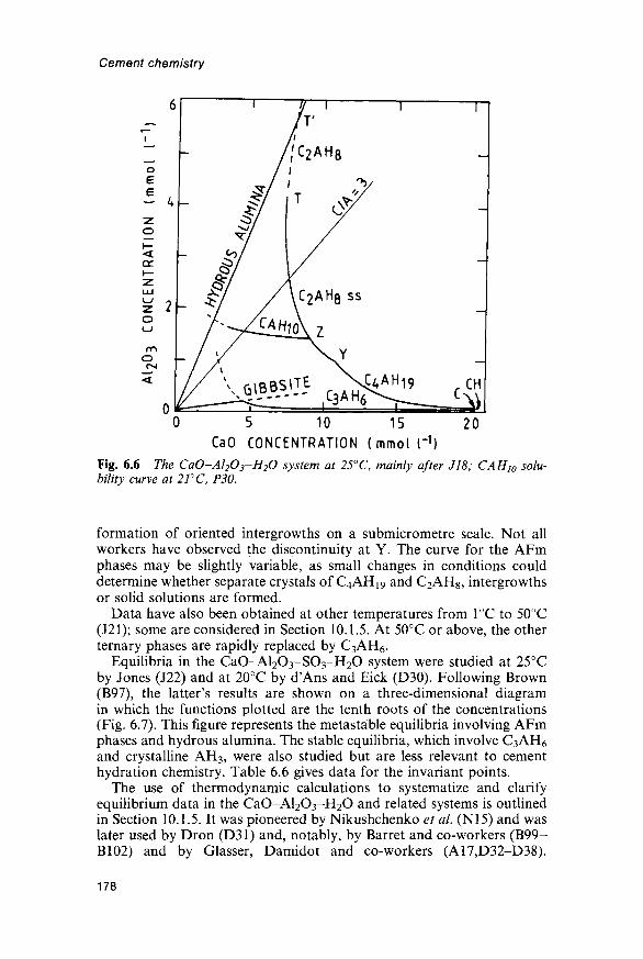
Cement chemistry
5 10 15CaO CONCENTRATION ( m m o i r 1 )
20
Fig. 6.6 The CaO-Al2O3-H2O system at 25°C, mainly after J18; CAH10 solu-bility curve at 2FC, P30.
formation of oriented intergrowths on a submicrometre scale. Not allworkers have observed the discontinuity at Y. The curve for the AFmphases may be slightly variable, as small changes in conditions coulddetermine whether separate crystals of C4AHi9 and C2AH8, intergrowthsor solid solutions are formed.
Data have also been obtained at other temperatures from 1°C to 50°C(J21); some are considered in Section 10.1.5. At 50°C or above, the otherternary phases are rapidly replaced by C3AH6.
Equilibria in the CaO-Al2O3-SO3-H2O system were studied at 25°Cby Jones (J22) and at 20°C by d'Ans and Eick (D30). Following Brown(B97), the latter's results are shown on a three-dimensional diagramin which the functions plotted are the tenth roots of the concentrations(Fig. 6.7). This figure represents the metastable equilibria involving AFmphases and hydrous alumina. The stable equilibria, which involve C3AH6
and crystalline AH3, were also studied but are less relevant to cementhydration chemistry. Table 6.6 gives data for the invariant points.
The use of thermodynamic calculations to systematize and clarifyequilibrium data in the CaO-Al2O3-H2O and related systems is outlinedin Section 10.1.5. It was pioneered by Nikushchenko et al. (N15) and waslater used by Dron (D31) and, notably, by Barret and co-workers (B99-B102) and by Glasser, Damidot and co-workers (A17,D32-D38).
178

Hydrated aluminate, ferrite and sulfate phases
CaSCk
AI2O3
CaO
Fig. 6.7 Metastable equilibria in the CaO-Al2O3-SO3-H2O system at 20°C,showing crystallization surfaces, based largely on the data ofd'Ans and Eick (D30).Concentrations are expressed as logarithms to the base 10 of values in mol l~l and,following B97, are plotted on scales proportional to their tenth roots. Concentrationsat the lettered invariant points are given in Table 6.6.
Equilibrium solubility surfaces were thus calculated for the CaO-Al2O3-SO3-H2O system at 25°C, 50°C and 85°C (A17,D32,D33). If allowancewas made for the effects of different forms of AH3, the results at 25°Cagreed well with those found experimentally. Contrary to an earliersuggestion (S67), they showed that monosulfate was always metastablerelative to C3AH6 and ettringite in the system at 25°C, but that attemperatures above 45°C monosulfate became stable at the expense ofettringite over an increasingly wide range of concentrations. Ogawa andRoy (O17) studied the stability of ettringite in the presence of water athigher temperatures and summarized earlier work. Ettringite appears tobe stable in water up to at least 90°C at atmospheric pressures, 130°C at6-7 MPa or 145°C at 27MPa. The principal decomposition product ismonosulfate. In cement pastes, it normally decomposes at about 70°C,because the C-S-H competes strongly for SO^" ions (B76), but ifsufficient SO^" is present, it persists to higher temperatures (H39,K34).
179
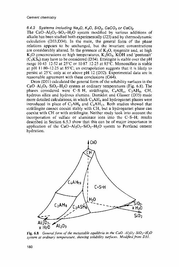
Cement chemistry
6.4.3 Systems including Na2O, K20, SiO2, CaCO3 or CaCI2
The CaO-Al2O3-SO3-H2O system modified by various additions ofalkalis has been studied both experimentally (J23) and by thermodynamiccalculation (D33,D34). In the main, the general form of the phaserelations appears to be unchanged, but the invariant concentrationsare considerably altered. In the presence of K2O, syngenite and, at highK2O concentrations or high temperatures, K2SO4, KOH and 'pentasalt'(C5KS6) may have to be considered (D34). Ettringite is stable over the pHrange 1043-12-52 at 25°C or 10-87-12-25 at 85°C. Monosulfate is stableat pH 11-80-12-25 at 85°C; an extrapolation suggests that it is likely topersist at 25°C only at or above pH 12 (D32). Experimental data are inreasonable agreement with these conclusions (G64).
Dron (D31) calculated the general form of the solubility surfaces in theCaO-Al2O3-SiO2-H2O system at ordinary temperatures (Fig. 6.8). Thephases considered were C-S-H, stratlingite, C4AH^, C2AH8, CH,hydrous silica and hydrous alumina. Damidot and Glasser (D35) mademore detailed calculations, in which C3AH6 and hydrogarnet phases wereintroduced in place of C2AH8 and C4AH13. Both studies showed thatstratlingite cannot coexist stably with CH, but a hydrogarnet phase cancoexist with CH or with stratlingite. Neither study took into account theincorporation of sulfate or aluminate ions into the C-S-H; resultsdescribed in Section 6.5.3 show that this can be of major importance inapplication of the CaO-Al2O3-SiO2-H2O system to Portland cementhydration.
SiO2
A12&3.XH2O
Fig. 6.8 General form of the metastable equilibria in the CaO-Al2O3-SiO2-H2Osystem at ordinary temperature, showing solubility surfaces. Modified from D31.
AI2O3
180

Hydrated aluminate, ferrite and sulfate phases
The CaO-Al2O3-CaCO3-H2O system has been studied by thermo-dynamic calculation (B101,B102,D36,D37,S75), as has the CaO-Al2O3-CaCl2-H2O system (D38). In the latter system at 25°C,C3A.CaCl2- 10H2O has a stable phase field (A18JD38).
6.4.4 Preparative methodsMylius (M69) described the preparation of many calcium aluminatehydrates and related compounds. As with C-S-H, it is normally essentialto exclude atmospheric CO2 and to avoid prolonged contact with glassapparatus. Dosch and Keller (D27) described methods for obtainingmany AFm phases by anion exchange or other special procedures.
The C4A and C2A hydrates are most conveniently prepared by addingcalcium oxide or saturated CH solution to a supersaturated calciumaluminate solution obtained by shaking CA or white calcium aluminatecement (Section 10.1.1) with water. Such solutions typically contain up toabout l-2g CaO I"1 and 1-9 g A12O31"1, these concentrations dependingon the shaking time, temperature, proportioning and particle size of thestarting material. The amount of calcium oxide or CH solution addedmust be such as to produce the desired compound and a solution inmetastable equilibrium with it, in accordance with the solubility relations(Fig. 6.6 and Table 6.6). CAHi0 may be prepared in this way at 5°C, nocalcium oxide or CH being added to the supersaturated solution. C3AH6may be prepared from metallic aluminium and CH solution at 50°C, orby hydrothermal treatment of C3A or a mixture of calcium oxide andAH3 with water at 150°C.
Ettringite may be prepared by mixing solutions of CH, gypsum andA12(SO4)3. Mylius used 1000ml of saturated CH (l-2g CaO I"1) dilutedto 1200 ml (A), 530 ml of saturated gypsum (2-05 g CaSO4l~
1; B) and asolution of l-78g of A12(SO4)3- 18H2O in 770 ml of water (C). SolutionsA and B were first mixed, and solution C then added, with shaking. Themixed solution was shaken at 18°C until an initially precipitated gel hadbeen replaced by crystalline material. The molar proportions are 8CaO:lAl2(SO4)3:3CaSO4.
Monosulfate is troublesome to prepare. Mylius mixed 500 ml of asupersaturated calcium aluminate solution (649 mg CaO and 969 mgA l ^ l " 1 ) at 18°C, with shaking, with 2924ml of saturated CH (l-25gCaOT1) and 334ml of saturated gypsum (193gCaSO4r1). After30min, crystallization was complete; the mixture was filtered, washedfour times with a little water followed by 96% ethanol and ether, anddried over CaCl2 and soda lime without evacuation. Monosulfate mayalso be prepared hydrothermally (All).
Carlson and Berman (C34) described the preparation of QACHn andC6AC3H32. C4ACHn was obtained using a supersaturated calciumaluminate solution, saturated CH and Na2CO3. The most satisfactorymethod for preparing C6AC3H32 employed a supersaturated calciumaluminate solution, NH4HCO3 and a concentrated CH solution contain-ing sucrose.
181

Cement chemistry
Crammond (C38) reviewed reports of the formation of thaumasite inthe laboratory and in deteriorated building materials. It forms readily at4°C from mixtures that contain the appropriate ions and also 0-4-1-0%of reactive alumina. It does not form at 25°C or above. A little Al3+ maybe essential, and reported failures to reproduce published syntheses maybe due to the use of Al-free materials.
6.5 Hydration reactions of the aluminate and ferrite phases6.5.7 Reaction of C3A with water or with water and calcium hydroxideThe reactions of C3A and C4AF with water, alone or in the presence ofcalcium hydroxide or sulfate or both, have been widely studied for thelight they may cast on the mechanism of Portland cement hydration, andespecially on the action of gypsum in controlling setting. The results ofsuch studies must be interpreted with caution. The aluminate and ferritephases in Portland cement clinker differ greatly in composition from thepure compounds. In normal clinkers, they are intimately mixed with eachother and react in an environment chemically and microstructurallyinfluenced, and perhaps dominated, by the silicate phases, and which isfurther affected by the presence of alkalis. Small quantities of CO2, whichare likely to be present in real concretes, have important effects on thereactions.
Many studies have shown that the reaction of C3A with water insuspensions at ordinary temperatures gives C2AH8 and C4AH19, whichare subsequently converted into C3AH6. At temperatures above about30°C or in pastes, conversion is rapid and the AFm phases may not beobserved; local temperature increase due to the strongly exothermicnature of the reaction probably has an important effect. Studies usingSEM and XRD (B103) or HVTEM (S53) indicate that an amorphous gelis formed as a precursor to the crystalline phases; it appears to consist ofthin foils growing on the C3A surface. Direct evidence on its composition,obtained using ESCA, is conflicting (B104,J24); indirect evidence fromthe CaO/Al2O3 ratio of the solution suggests that the initial ratio in thesolid product is below 3-0 (B105,G65). In agreement with this conclusion,inspection of Fig. 6.6 indicates that the first product to form might beeither C2AH8 or hydrous alumina, the latter tending to redissolve later.
In pastes, the hydration of C3A, as followed calorimetrically, is slightlyretarded if CH is present (C39). The products are essentially the same asthose formed in the absence of CH, but the crystals of AFm phases aresmaller (G66). In dilute suspensions, the first crystalline product to form isC4AHi9; this causes the CaO/Al2O3 ratio in the solution to decrease (B105).
6.5.2 Reaction of C3A with water in the presence of calcium sulfateStudies using calorimetry, electron microscopy, XRD and DTG(C39,S76,S77) have shown that this reaction occurs in two stages, bothof which are strongly exothermic. The first stage is characterized by apeak in the heat evolution curve during the first 30 min, and yieldsettringite. In the second stage, which is characterized by a peak typically
182

Hydrated aluminate, ferrite and sulfate phases
occurring at 24-48 h, the ettringite reacts further and AFm phases areformed. The reactions may be represented by the following equations:
C3A +3CSH2 + 26H2O^C6AS3H32 (6.2)
2C3A + C6AS3H32 + 4H2O ^3C4ASH12 (6.3)
C3A +CH + 12H2O^C4AH13 (6.4)
where the C4AHi3 forms a solid solution with monosulfate. Each of thesereactions occurs to an extent that depends on the ratio of gypsum to C3A.C4AH13 can form only if calcium hydroxide is also present.
Studies by TEM (B106) and HVTEM (S53) show that, as in theabsence of gypsum, the formation of a distinctly crystalline reactionproduct is preceded by that of a layer of amorphous or poorly crystallinematerial having a foil or irregular, platey morphology on the surface ofthe grains. There is no direct evidence concerning the composition of thismaterial, but Brown (B97) concluded from a consideration of the phaseequilibria (Fig. 6.7) that, depending on the concentrations in the solutionin contact with the C3A when the latter began to react, the first A12O3-containing phase to form might be either AH3 or ettringite. Themorphology of the product does not support the view that it is ettringite,though it might be an amorphous material of similar composition.Formation of a crystalline precursor to the ettringite has also beenreported (C40).
The ettringite produced in the first stage of reaction tends to form asstubby, prismatic crystals up to 1 fim long and close to the C3A surfaces,but it is also formed away from these surfaces, thus indicating a through-solution mechanism (M77,S53). Further evidence for the latter isprovided by the observation that, in pastes of C3A and C3S withgypsum, some of the C3A grains form hollow shells only partly occupiedby unreacted starting material or hydration products (S53). The ettringitecrystals are readily damaged by the electron beam. Longer needles, ofhigh aspect ratio, can also form. The amount of available space (M77),pH (B106) and sulfate ion concentration (S53) have been variouslyconsidered to control the morphology.
Addition of gypsum substantially retards reaction of the C3A in thepure system; CH increases the effect (C39). Gypsum also retards C3Ahydration in cement pastes (T35; section 7.6.1). The effect of gypsum hasbeen attributed to the protective action of a layer of ettringite (C39,S77),but it has been queried whether this layer is sufficiently impermeable tohave such an effect (M77). Retardation has also been attributed to anunderlying layer of hydrous alumina (C41) or AFm phase (G67,P31); thisview is consistent with the electron microscopic evidence mentionedearlier. The retarding properties of such a layer might well depend on itscomposition, thus explaining the different rates of reaction observed inthe absence of admixtures and with CH or gypsum or both. Retardationhas also been attributed to the blocking of active sites on a modified C3Asurface by adsorbed sulfate ions (F32,S78); however, Na2SO4 has nosignificant effect on the rate of reaction (C39).
183
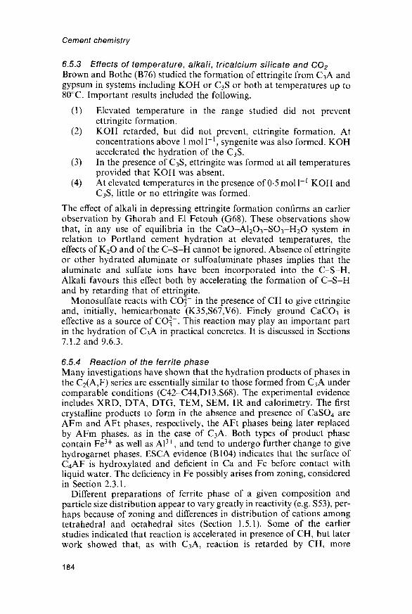
Cement chemistry
6.5.3 Effects of temperature, alkali, tricalcium silicate and C02
Brown and Bothe (B76) studied the formation of ettringite from C3A andgypsum in systems including KOH or C3S or both at temperatures up to80°C. Important results included the following.
(1) Elevated temperature in the range studied did not preventettringite formation.
(2) KOH retarded, but did not prevent, ettringite formation. Atconcentrations above 1 mol I"1, syngenite was also formed. KOHaccelerated the hydration of the C3S.
(3) In the presence of C3S, ettringite was formed at all temperaturesprovided that KOH was absent.
(4) At elevated temperatures in the presence of 0-5 mol I"1 KOH andC3S, little or no ettringite was formed.
The effect of alkali in depressing ettringite formation confirms an earlierobservation by Ghorab and El Fetouh (G68). These observations showthat, in any use of equilibria in the CaO-Al2O3-SO3-H2O system inrelation to Portland cement hydration at elevated temperatures, theeffects of K2O and of the C-S-H cannot be ignored. Absence of ettringiteor other hydrated aluminate or sulfoaluminate phases implies that thealuminate and sulfate ions have been incorporated into the C-S-H.Alkali favours this effect both by accelerating the formation of C-S-Hand by retarding that of ettringite.
Monosulfate reacts with CO3~ in the presence of CH to give ettringiteand, initially, hemicarbonate (K35,S67,V6). Finely ground CaCO3 iseffective as a source of CO3~. This reaction may play an important partin the hydration of C3A in practical concretes. It is discussed in Sections7.1.2 and 9.6.3.
6.5.4 Reaction of the ferrite phaseMany investigations have shown that the hydration products of phases inthe C2(A,F) series are essentially similar to those formed from C3A undercomparable conditions (C42-C44,D13,S68). The experimental evidenceincludes XRD, DTA, DTG, TEM, SEM, IR and calorimetry. The firstcrystalline products to form in the absence and presence of CaSO4 areAFm and AFt phases, respectively, the AFt phases being later replacedby AFm phases, as in the case of C3A. Both types of product phasecontain Fe3+ as well as Al3+, and tend to undergo further change to givehydrogarnet phases. ESC A evidence (B104) indicates that the surface ofC4AF is hydroxylated and deficient in Ca and Fe before contact withliquid water. The deficiency in Fe possibly arises from zoning, consideredin Section 2.3.1.
Different preparations of ferrite phase of a given composition andparticle size distribution appear to vary greatly in reactivity (e.g. S53), per-haps because of zoning and differences in distribution of cations amongtetrahedral and octahedral sites (Section 1.5.1). Some of the earlierstudies indicated that reaction is accelerated in presence of CH, but laterwork showed that, as with C3A, reaction is retarded by CH, more
184

Hydrated aluminate, ferrite and sulfate phases
strongly by gypsum and still more strongly by the two together. Undercomparable conditions, C4AF appears normally to react more slowlythan C3A, though, initially at least, the reverse may sometimes be the case(S53). It appears generally agreed that the rate of reaction of the ferritephase decreases with the Fe/Al ratio.
Several investigators have noted that the ratio of Al to Fe in theproduct phases tends to be higher than that of the starting material, andhave concluded that an iron(III) oxide or hydroxide is also formed.Teoreanu et al (T36), using Mossbauer spectroscopy and XRD,concluded that the hydration products formed from C2F or C4AF atordinary temperatures included FH3. With C2F above 75°C, this wasreplaced by hematite. Fukuhara et al. (F33) concluded from calorimetricevidence that the AFt phase formed from C4AF in pastes at 20°C had anAl/Fe ratio of about 3 and postulated that FH3 was also formed. Rogersand Aldridge (R29) found that in C2(A,F) preparations hydrated at 4°Cthe only product detectable by XRD was C4(A,F)Hi9, but evidence fromX-ray microanalysis showed that an amorphous iron oxide or hydroxidewas also formed. In products formed at 80°C hematite was identified byXRD, microanalysis and Mossbauer spectroscopy. Hydrogarnet phasesformed from C6A2F or C4AF contained only small proportions of iron,as did that formed from C6AF2 at 150°C; those formed from C6AF2 at21°C or 80°C had Fe/(A1 + Fe) ratios of 0-30-0-35. Fortune and Coey(F34), using XRD and Mossbauer spectroscopy, similarly found thathydrous iron(III) hydroxide was present among the products of C4AFhydrated at 72°C. The hydrogarnet phase that was the main product hadan Fe/(A1-f Fe) ratio of 0-22. If CH was added, this ratio was increasedto 0-32, but the hydrogarnet formed in presence of gypsum was almostfree from Fe3+.
Brown (B107) concluded that in C4AF hydration in presence of CaSO4the early product was C2AH8 or hydrous alumina, and that it wasfollowed by formation of an AFt phase containing little or no Fe3+; an
Table 6.7 Standard enthalpies of formation (AH®;kJmol x) for somecompounds relevant to hydration of the aluminate and ferrite phases (25°C exceptwhere otherwise stated)
Compound AH°{ Ref. Compound AH°f Ref.
C3A -3587-8 WIO C6AS3H32
C4AF(20°C) -50903* T8 C4ASH12
C6A2F -8104-9 N12 C4AH13
CSH2 -20226 WIO C4ACH1068CSH0.5(/3) -1514-65 WIO C3AH6
CH -9861 WIO H2O (liquid)
* Using data for oxides, from WIO.
185
-17539-17 528-8778-8752-8318-8176-5548-285-83
WIOS68WIOS79H40WIOWIOWIO

Cement chemistry
Table 6.8 Enthalpy changes for some hydration reactions ofC3A, calculated fromthe data in Table 6.7
Reaction AH (kJ per mole of C3A)
C3A + 3CSH2 + 26H2O^C6AS3H32 -452C3A + CSH2 + 10H2O-^C4ASH12 -309C3A + CH + 12H2O^C4AH13 -314C3A + 6H2O ^C3AH6 -2452C3A-fC6AS3H32 +4H2O -+3C4ASH12 -238
iron oxide gel containing some Ca2+ was also formed. The conclusionregarding the later products agrees substantially with that of Fukuharaet al. (F33). The tendency to form iron oxide or hydroxide may be con-nected with the fact that species containing Al3+ can migrate in pastesrelatively easily, whereas those containing Fe3+ cannot, and are thuslargely confined to the space originally occupied by the anhydrous mat-erial from which they come (T37).
6.5.5 Enthalpy changesTable 6.7 gives standard enthalpies of formation of some relevantcompounds, and Table 6.8 gives enthalpy changes for hydration reactionsof C3A calculated from them. The strongly exothermic nature of these reac-tions is apparent. Lack of data for the standard enthalpies of the hydrationproducts containing iron precludes similar calculations for the ferritephase. For the hydration of C3A to give C3AH6, Lerch and Bogue (L24)obtained an experimental value of —234kJmol"1; other workers haveobtained similar results. Experimental determinations of the enthalpy ofhydration of C4AF have given -203kJmol~1 (products not established;L24), and, in the presence of excess CH to give hydrogarnets,-193kJmol ' 1 for C4AF and -208kJmol"1 for C4A0.6sF0.32 (B63). ForC4AF in the presence of gypsum to give ettringite and FH3, a value of-352kJmol"1 has been reported (F33). Houtepen and Stein (H40) gavestandard enthalpies of formation of some other AFm phases determinedexperimentally, and Babushkin et al. (B65) gave values for othercompounds estimated on the basis of crystal chemistry.
186

7 Hydration of Portland cement
7.1 Evidence from X-ray diffraction, thermal analysis andinfrared spectroscopy
7.1.1 Introduction; formation of calcium hydroxide and C-S-HStudy of the hydration process and products in concretes, and even inmortars, is complicated by the presence of the aggregate. Someconcentration of the paste can usually be effected by crushing, mildgrinding and sieving, but with most experimental techniques, much moredetailed information can be obtained from studies on pastes. Because ofthis, most investigations have related to pastes and, unless otherwisestated, this chapter relates to ordinary Portland cements hydrated inpastes at 15-25°C and w/c ratios of 045-0-65. However, data for pastesstored under constant external conditions may not be fully applicable tothe paste fraction of concrete. Much of the paste in a normal concrete isclose to aggregate surfaces and differs from bulk paste; in real concretes,temperature and other parameters inevitably vary both with age and withlocation within the material. Of the various experimental approaches,microstructural studies are probably the ones for which the presence ofan aggregate interferes least with the quality of the data that can beobtained.
XRD powder studies on cement pastes have been reported by manyinvestigators (e.g. C45,M78). Gypsum and other calcium sulfate phasesare usually no longer detectable after, at most, 24 h, and the clinkerphases are consumed at differing rates, alite and aluminate phase reactingmore quickly than belite and ferrite. The ratio of belite to alite thusincreases steadily, and after about 90 days at most, little or no alite oraluminate phase is normally detectable. The rates of disappearance of thephases present in the unreacted cement are considered more fully inSection 7.3.1. As with pure calcium silicate pastes, the principal productsare C-S-H and CH.
TEM studies show that a small proportion of the CH in cement pastesis cryptocrystalline and intimately mixed with the C-S-H (G69,V4). Thiscontrasts with the situation in pure C3S pastes (Section 5.1.3). Crypto-crystalline CH was also found in pastes made from calcium oxide andsilica of high w/s ratio and of blastfurnace slag activated by CH (G70).These observations may explain ones, reviewed by Barker (B108), that
187

Cement chemistry
the CH in cement pastes appears to contain small amounts of SiO2.A reported occurrence of amorphous CH in a Renaissance lime plaster(M79) was disproved (N16), but a natural occurrence of amorphous CHhas been described (N17).
7.1.2 Formation of hydrated aluminate or sulfoaluminate phasesThe phases of these types that are observed depend on the cement com-position, the time and other conditions of hydration, the presence orotherwise of CO2 and the drying conditions. With most ordinary Portlandcements at ordinary temperatures, ettringite peaks are detectable in theXRD pattern within a few hours and increase in intensity to a maximum,often at about 1 day. The 0-973 and 0-561 nm peaks are especially promi-nent, but many other peaks can often be detected, indicating that at leastsome of the ettringite is highly crystalline. Subsequently, peaks of AFmphases usually appear and are somewhat variable. Where present, theynormally comprise hk.O peaks at about 0-288 nm (11-0) and 0-166 nm(30-0) and the first- and second-order basal reflections corresponding toone or more layer thicknesses. The AFm peaks tend to be broad and,taking into account also the amounts likely to be present, the XRDevidence suggests that much of the AFm material is poorly crystalline.The AFm peaks may be observed within 24 h, but are sometimes onlyobserved after some days or even months.
In one type of behaviour, the ettringite peaks weaken after about 24 hand may ultimately disappear, while peaks of monosulfate (cf =0-89nm)or a monosulfate solid solution appear and gradually become stronger.This behaviour is common in laboratory-prepared pastes from whichCO2 has as far as possible been excluded, and arises from the reac-tions represented by equations 6.2-6.4 (Section 6.5.2). Sulfate ion isreleased rapidly from the clinker sulfates and calcium sulfate, whereasA1(OH)4 is released, mainly from the aluminate phase, more slowly, andthe resulting high ratio of available SO^" to available A1(OH)4 favoursthe formation of ettringite. By about 24 h, substantially all the SO^" hasbeen released, and the continuing supply of A1(OH)4 leads to thedissolution of ettringite and precipitation of monosulfate. The reactionsare in reality more complex than the above. An amorphous gel is formedin addition to the ettringite; it seems to be high in A12O3 and SiO2, butalso to contain significant proportions of Ca2+ and SO^" (Section 7.2.2).In addition, the C-S-H takes up some of the SO4" ions. Not all of thesulfate released from the gypsum and clinker sulfates thus enters theettringite directly. Because of the lower rate of release of the A1(OH)4 ,sulfate may enter the amorphous gel and the C-S-H, from which it ispartly or wholly transferred to ettringite as more A1(OH)4 becomesavailable.
The AFm phase ultimately formed in these reactions will only have themonosulfate composition if the effective ratio of SO3 to A12O3 is 1-0.With cements of relatively high SO3/A12O3 ratio not all of the ettringitemay disappear; conversely, with those in which this ratio is low, themonosulfate may undergo anion exchange, giving a solid solution in
188

Hydration of Portland cement
which the SO^" is partly replaced by OH". With a sulfate-resistingPortland cement, ettringite has been reported to persist for periods of upto 1 year, but eventually to disappear, probably due to incorporation ofSO^" and A1(OH)4 in the C-S-H (G5). Monosulfate was not detected.In another study, substantial contents of ettringite were found at ages upto 60 days, together with poorly crystalline AFm phase (H41).
Petrographic studies on field concretes appear very commonly to showthe presence of ettringite, but monosulfate has rarely been reported.Ettringite could persist, even with cements of low SO3/A12O3 ratio,because of a reaction with CO2", which reacts with monosulfate in thepresence of Ca(OH)2 to produce ettringite and hemicarbonate (S67,S80):
3C4ASH12 + 2Ca2+ + COf-+2OH"+ 19H2O
- C6AS3H32 + 2C4AC0.5Hl2 (7.1)
Of every three moles of C4ASH12, one is decomposed, its content of A12O3going to form ettringite, and two undergo anion exchange, giving hemi-carbonate. Further reaction with CO3~ causes the hemicarbonate to bereplaced by monocarbonate, and, ultimately, the AFm and AFt phasesare destroyed. In a cement paste, ettringite and hemicarbonate may beformed directly. Kuzel and Meyer (K35) noted that a few tenths of aper cent of CO2 (referred to the mass of cement) could suffice to preventthe formation of monosulfate in a typical cement paste, and concludedthat, as a result, ettringite was likely to persist indefinitely. The extent towhich this happens in field concretes is largely a matter for conjecture.
In those cement pastes in which monosulfate is formed, XRD usuallyshows this to be the 12-hydrate, with d «0-89nm. Intensive drying cancause dehydration to the 10-hydrate, with c/^0-82nm, and can alsocause the ettringite peaks to disappear (C45). On the other hand, it hasbeen reported that the 14-hydrate is present in undried pastes (K35).
With the probable exception of sulfate-resisting types (G5), modernPortland cements do not yield amounts of hydrogarnet detectable byXRD on hydration at ordinary temperatures, though a poorly crystallineproduct probably approximating to a hydrogarnet has been found byTEM (Section 7.4.2). Luke and Glasser (L30) found a hydrotalcite-typephase by XRD in a residue from which the other phases had beenremoved by chemical extraction. Calcite, if present, is detectable by asharp peak superimposed on the maximum in the C-S-H band at0-3035 nm, and if in sufficient quantity by additional peaks.
7.1.3 Evidence from differential thermal analysis andinfrared spectroscopy
Bensted and Varma (B109) summarized the use of DTA and IR spectros-copy for the examination of cement pastes. Both are mainly useful forfollowing the phase changes in relatively young pastes. Figure 7.1 showsDTA curves for pastes of a typical Portland cement at ages up to 7 days.The peaks at 145°C and 165°C given by the unhydrated cement are due togypsum, and that at 485°C to a small amount of CH formed during
189

Cement chemistry
H5
135
135,
J140
120 J
135 .
115 J7
^65
.145
\16OW7C
1
1
I\195
UNHYDRATED_ ^
15 MIN
I— '1 HOUR
-
16 HOURS
24HOURS
490,
485
480—
530
A530
/A
oQZLU
oLU
120
?125
140
\i85
3
5
7
DAYS
'
DAYS
505
DAYS
510J
550
n
550^
k550
A/Fig. 7.1 curves for pastes of a typical Portland cement. From B109.
storage, probably by hydration of free lime. The peak at 135-140°C thatappears within 15 min is due to ettringite; its intensity passed through amaximum at 16-24h. The peak at 115-125°C is due to C-S-H or cementgel, and that at 530-550°C to CH. The relatively large crystals of thisphase that are formed on hydration in the paste decompose at a highertemperature than the smaller ones formed on hydration during storage.The peak at 185-200°C is due to an AFm phase or phases. One wouldexpect all these peak temperatures to vary with the technique used, butthat their relative positions would be essentially unchanged.
In the first effective studies of hydrated cements by DTA, Kalousek andco-workers (K29,K34,K36) observed the early formation of ettringiteand its subsequent replacement by monosulfate, or a monosulfate solidsolution. This later disappeared, and the authors concluded that all theoxide components were ultimately taken up by a material which theytermed 'Phase X'. Subsequent work indicates that this was essentiallyC-S-H. No C3AH6 or other hydrogarnet phases were detected. Quanti-tative or semi-quantitative determinations of gypsum and ettringiteindicated that less than half the total SO3 present could be accounted forby AFm and AFt phases. The successive formation of ettringite and AFmphase, and the disappearance of the latter, took place more rapidly as thetemperature increased, and at 100°C the entire sequence appeared to becompleted in 3-4 h.
Infrared absorption spectra (B109) of unhydrated cements typicallyshow moderate to strong bands at 525 and 925 cm"1 due to alite, and at
190

Hydration of Portland cement
1120 and 1145 cm"1 from S-O stretching vibrations, and weak bands inthe 1650 and 3500 cm"1 regions due to H2O molecules. The early forma-tion of ettringite on hydration is shown by a change in the sulfateabsorption to a singlet centred at 1120cm"1, and the subsequentreplacement of ettringite by monosulfate by a further return to a doubletat 1100 and 1170 cm"1. The hydration of the silicate phases causes a shiftin the broad Si-O absorption band from 925 to 970 cm"1. After severaldays, the silicate absorption tends to obscure that from sulfate. Changesalso occur in the H2O bending band near 1650 cm"1 and in the H2O or OHstretching bands at 3100-3700 cm"1; in the latter region, CH gives a peakat 3640 cm"1, ettringite one at 3420 cm"1 and a weaker one at 3635 cm"1
and monosulfate ones at 3100, 3500 (broad), 3540 and 3675 cm"1. Thecomplexity and partial overlapping of these absorptions lessens theirutility. The IR spectra also indicate that both the ettringite and theAFm phases formed in cement pastes are less crystalline than the purematerials, and that the AFm phases become poorer in SO^" as hydra-tion proceeds.
7.2 Microstructure7.2.1 Evidence from light and electron microscopyStudies on the microstructures of cement pastes have given resultsbroadly similar to those on calcium silicate pastes (Section 5.3.1), thoughwith some important differences at early ages. As with calcium silicatepastes, the first effective studies were made using light microscopy of thinsections (B53), which were successively augmented by TEM of groundand redispersed material (C22,G42), SEM of fracture surfaces(C23,D16,W19), X-ray (T37,U13,U14) or backscattered electron imaging(D39,S35,S37,S51,S81) of polished sections, TEM examination of ion-thinned sections (R17,R32,V4) and other techniques.
The development of microstructure is considered in Sections 7.2.2-7.2.4. The broad microstructures of pastes more than about 28 daysold, first described by Scrivener and Pratt (S35), are similar to those ofC3S pastes. Figure 7.2 shows a typical backscattered electron image,obtained under conditions maximizing contrast from compositionaldifferences. The following types of region are distinguishable by theirdiffering grey levels.
(1) The brightest areas are of unreacted clinker phases. Individualcement grains are usually polymineralic and, as in a clinker(Section 4.3.1), the different phases within them can be distin-guished by their differing grey levels or by X-ray microanalysis.
(2) To varying extents, the clinker phases are replaced by hydrationproducts that have formed in situ, and which appear darker onthe backscattered electron image. Most noticeably, the alite andbelite are replaced by material approximating in composition tothe C-S-H of calcium silicate pastes, but which tends to have ahigher Ca/Si ratio and contains small amounts of other elements,especially Al, Fe and S. Initially, these hydration products are
191
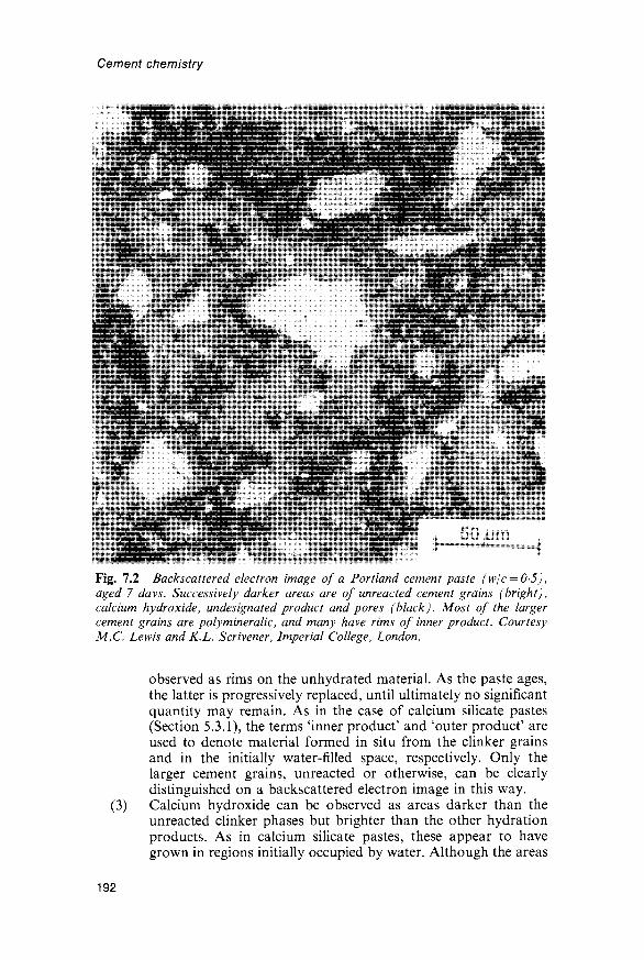
Cement chemistry
Fig. 7.2 Backscattered electron image of a Portland cement paste (w/c = 0-5),aged 7 days. Successively darker areas are of unreacted cement grains (bright),calcium hydroxide, undesignated product and pores (black). Most of the largercement grains are polymineralic, and many have rims of inner product. CourtesyM.C. Lewis and K.L. Scrivener, Imperial College, London.
(3)
observed as rims on the unhydrated material. As the paste ages,the latter is progressively replaced, until ultimately no significantquantity may remain. As in the case of calcium silicate pastes(Section 5.3.1), the terms 'inner product' and 'outer product' areused to denote material formed in situ from the clinker grainsand in the initially water-filled space, respectively. Only thelarger cement grains, unreacted or otherwise, can be clearlydistinguished on a backscattered electron image in this way.Calcium hydroxide can be observed as areas darker than theunreacted clinker phases but brighter than the other hydrationproducts. As in calcium silicate pastes, these appear to havegrown in regions initially occupied by water. Although the areas
192

Hydration of Portland cement
appear discrete on two-dimensional sections, they are not nec-essarily so in the three-dimensional material. They can engulfsmall cement grains. The CH tends to be more finely dispersed inpastes of low w/c ratio.
(4) The remaining space, which forms the matrix in which the aboveregions appear to be embedded, consists of material varying ingrey level from material similar to the in situ product to darkerregions, representing pores. Like the CH, these appear discrete intwo dimensions, but are not necessarily so in three. This materialis often called 'outer product', but in reality includes not onlyproducts formed in what was originally water-filled space, butalso that formed in space initially occupied by the interstitialmaterial or by the smaller cement grains, the outlines of whichcan no longer be distinguished. Various other terms, such as'undesignated product', matrix material' and 'groundmass' havebeen used. For laboratory-prepared pastes of most cements, themajority of individual microanalyses of the hydration product inthese regions have shown compositions varying between thoseof C-S-H and either AFm phase or CH (H4). Regions largeenough for accurate microanalysis on polished surfaces (~5/xm)are rarely of pure AFm phase.
7.2.2 The early period of hydrationMany features of the development of microstructure in cement pastes aresimilar to those observed in C3S pastes (Section 5.3.1), but there are someimportant differences. As with C3S pastes, it is convenient to consider theprocess in terms of early, middle and late periods of hydration, withdivisions at approximately 3 and 24 h after mixing. Figure 7.3 showsdiagrammatically the sequence of changes undergone by a typical, poly-mineralic cement grain, as given by Scrivener, on whose conclusions (S37)the following is largely based.
Studies by HVTEM show that at high dilutions a gel layer ormembrane forms over the surfaces of the grains soon after mixing(D17,G45). A product of similar appearance has been observed in pastesof C3A with gypsum (S53), and, less distinctly, in pastes of cement ofnormal w/c ratios (J25,S37). It is probably amorphous, colloidal and richin alumina and silica, but also containing significant amounts of calciumand sulfate, the composition varying with that of the underlying surface.Within about lOmin, stubby rods of AFt phase are also seen (D40,D41).They are typically some 250 nm long and 100 nm thick. Studies using wetcells show them to occur both on the surfaces of the grains, and at somedistance away (S37,S53; Fig. 7.3b). They are probably more abundantnear the surfaces of the aluminate phase, and appear to nucleate in thesolution and on the outer surface of a layer of gel. On drying, this layershrinks, and the AFt crystals fall back onto the surfaces of the cementgrains. The early products thus differ in morphology and compositionfrom the exfoliating foils or honeycombs of C-S-H that have beenobserved in C3S pastes.
193

GEL
10pm
Q)
Un
hyd
rate
dS
ectio
n
of
po
ly-
min
eral
ic
gra
in(s
cale
of
in
ters
titi
alph
ase
is s
light
lyex
agg
erat
ed).
O CD CD 3 Co" •5
b)
~10m
in
c)
-10h
d)
-1
8h
e)
1~3d
oys
f)
-Ud
ay
sS
ome
C3A
(&
/or
Fss)
R
eact
ion
of
C
3S t
o
Sec
on
dar
y hy
drat
ion
C
3A r
eact
s w
ith
an
y S
uffic
ient
in
ner*
C
6-H
reac
ts
wit
h
calc
ium
p
rod
uce
ou
ter'
pro
du
ct
of
C3A
(X/o
r Fs
s} p
rodu
c- A
Ft
insi
de s
hell
form
ing
ha
s fo
rmed
to
fi
ll in
th
eh
g
long
rod
s of
AFt
. he
xago
nal
plat
es
of A
Fm. s
pac
e be
twee
n g
rain
an
dC
-S-H
*in
ner
' pr
oduc
t C
ontin
uing
fo
rmat
ion
of
shel
l. Th
e 'o
ute
r*
G-S
-Hst
arts
to
fo
rm
on
in
sid
e' in
ner'
pr
oduc
t re
duce
s ha
s be
com
e m
ore
fibro
us,
of s
hell
fro
m c
ontin
uing
se
para
tion
of
anhy
drou
shy
drat
ion
of
C3S
. g
rain
an
d
hyd
rate
d s
hell.
sulp
hat
e in
so
luti
on
.A
mor
phou
s, a
lum
inat
e-ri
ch g
el
form
s o
n
the
surf
ace
and
sh
ort
A
Ft
rod
s n
ucl
eate
at
edge
of
gel
and
in
so
luti
on
.
C-S
-H
on A
Ft
rod
n
et-
wo
rk
leav
ing
-1
um
bet
wee
n g
rain
su
rfac
ean
d
hyd
rate
d s
hel
l.
Fig
. 7.
3 D
evel
opm
ent
of m
icro
stru
ctur
e du
ring
the
hyd
rati
on o
f P
ortl
and
cem
ent.
Fro
m S
54.

Hydration of Portland cement
Early work using a wet cell, made at high w/c ratios, showed tubulargrowths radiating from the cement grains, which were considered to haveformed by a 'silicate garden' mechanism (D17). Later work showed thatthey were rich in calcium, aluminium and sulfur, and that they did notform if C3S was substituted for cement (B110). They have not beenobserved in the more recent studies made at normal w/c ratios, and donot appear to be a significant feature of normal cement hydration.
7.2.3 The middle period of hydrationDuring this period, which begins at about 3h and ends at about 24 h,some 30% of the cement reacts. It coincides with the period of strongheat evolution and is characterized by the rapid formation of C-S-H andCH. Studies using wet cells show that the undried C-S-H has a filmy,foil-like morphology (P32,S51), which on drying changes to give fibres(Type I C-S-H'), where space is freely available, or honeycombs orreticular networks ('Type II C-S-H'), where it is more restricted (Section5.3.1). The morphology is also affected by the presence of foreign ions,such as Cl~. Spherical aggregates of fibres some 2/xm in diameter,observed in dried material, probably result from the rapid reaction ofsmall cement grains consisting only of alite (S37). The CH forms massivecrystals in the originally water-filled space. Nucleation sites appear to berelatively few in number, and the growing crystals may engulf some of thesmaller cement grains. All these features of the process are similar tothose observed in C3S pastes.
The C-S-H forms a thickening layer around the cement grains(D40,P32), which engulfs and perhaps nucleates on the AFt rods(Fig. 7.3c). A significant amount has formed by 3h, and the grains arecompletely covered by 4h. The shells grow outwards; by about 12 h theyare some 0-5—1 O^m thick, and those surrounding adjacent grains arebeginning to coalesce. At this stage, which was called the cohesion point,fracture through the shells begins to supplant fracture between them.It coincides with the maximum rate of heat evolution and correspondsapproximately to the completion of setting. The structure of inter-connected shells has been considered to play an important part indetermining the mechanical and other properties, which thus depend onthe particle size distribution of the cement (D40).
Studies using ion-thinned sections, wet cells and backscattered electronimages of polished sections show that a space develops between the shelland the anhydrous material (K37,S37,S51,S53; Fig. 7.3c). In this respect,the hydration of cement differs from that of C3S, in which the C-S-Hgrows directly over the C3S surfaces, without any detectable separation(S53). By 12h, the spaces are up to 0-5 fim wide. They are likely to befilled with a highly concentrated or colloidal solution, and the shells areevidently sufficiently porous at this stage that ions can readily migratethrough them (S37). The existence of spaces shows that reaction proceedsby dissolution and precipitation; further evidence for this is provided bythe fact that the C-S-H also deposits on the surfaces of flyash particles, if
195

Cement chemistry
these are mixed with the cement (D42). Some other relatively unreactiveor inert admixtures behave in the same way.
Towards the end of the middle period, a renewed growth of AFtcrystals takes place (D41,P32,S53; Fig. 7.3d). They are markedly moreacicular than those formed earlier; their lengths are typically 1-2 /im, butsometimes up to 10 /mi. Their formation is associated with a shoulder onthe heat evolution curve (Section 7.5.1). Their formation implies anincrease in the rate of reaction of the aluminate, or less probably theferrite phase, which is probably related to the reaction of the alite (S3 7).
7.2.4 The late period of hydrationWith the decreasing permeability of the shells, C-S-H begins to depositalso on their insides, and its surface advances inwards more quickly thanthat of the alite retreats. Grains smaller than about 5/mi appear to reactcompletely before the end of the middle period, and before much materialhas deposited inside the shells; many that originally contained aluminatephase are empty (S37). The outer product from such grains is oftenabsorbed in the shells surrounding adjacent, larger grains. With largergrains, the spaces between shell and core fill up, and by about 7 days theyhave disappeared; at this stage, the shells are typically some 8 /im thickand consist mainly of material that has been deposited on their innersurfaces (Figs 7.3e and f; S37). The separations between shell and coreseen on polished or ion-thinned sections rarely exceed about 1 /mi.
Separated shells, up to at least 10 /mi across and sometimes completelyhollow, were originally observed on fracture surfaces (Bil l ) and have beencalled 'Hadley grains'. These are not observed on ion-thinned sections, andpossibly result from the core falling out during specimen preparation (S37).It would be difficult to reconcile any widespread occurrence of such cavitiesin a mature paste with the bulk density of the material (P32).
The concentration of SO^" must drop rapidly inside the shells as thealuminate phase reacts, and AFm phase often forms within the shells, anyAFt phase formed there initially being replaced by AFm as a result ofcontinued reaction of the aluminate phase (S37,S53). A single specimenmay show AFm phase within the shells and AFt phase outside them. TheXRD evidence (Section 7.1.2) shows that significant quantities of AFtphase may persist, apparently indefinitely; this is presumably materialthat has been precipitated outside the shells. If the SO4-concentration inthe solution outside the shells drops before these have sufficiently isolatedthe anhydrous grains, relatively large (~10/im) crystals of AFm phasecan form throughout the paste (S37).
After the spaces between shells and cores have filled up, reaction isslow and, in contrast to that occurring earlier, appears to occur by atopochemical mechanism (Section 5.8.4). In old cement pastes, threeregions of C-S-H can thus be distinguished in the relicts of the largerfully reacted grains (S81), viz. (a) an outer layer some 1/rni thick that hasformed through solution in originally water filled space, (b) a middlelayer some 8 /mi thick that has been deposited, also through solution, onthe inside of the shell and thus in space originally occupied by the cement
196

Hydration of Portland cement
grain, and (c) a central core, that has formed topochemically. As withC3S pastes, all the C-S-H probably has a foil morphology, which ismodified in varying ways by the effects of drying and in accordance withthe amount of space available.
Except in pastes many years old, the hydration of belite has proveddifficult to observe by electron microscopy (S37), although XRD evidenceshows that considerable reaction has occurred within 14 days. In a23-year-old paste studied by backscattered electron imaging, the belitegrains had reacted completely, but the original lamellar structureremained, providing further evidence of a topochemical mechanism(S81). The belite appears to react preferentially along the exsolutionlamellae. The reaction of the ferrite phase has similarly proved difficult toobserve, though backscattered electron imaging showed the formation inthe same sample of rims high in iron, and TEM examination hasprovided further data (Section 7.4.2).
7.3 Analytical data for cement pastes7.3.1 Unreacted clinker phasesThe experimental considerations applying to calcium silicate pastes(Sections 5.1 and 5.2) are equally relevant to cement pastes. Of themethods so far used in attempts to determine the degrees of reaction ofthe individual clinker phases as a function of time, QXDA (C46,D15,P33,T35) has proved much the most satisfactory. Procedures areessentially as for the analysis of a clinker or unreacted cement (Section4.5.3), but it is necessary to take account of overlaps with peaks from thehydration products, and especially with the C-S-H band at 0-27-0-31 nm. The water content of the sample must be known, so that theresults can be referred to the mass of anhydrous material. If a sample ofthe unhydrated cement is available, and its quantitative phase composi-tion has been determined, it may be used as the reference standard for theindividual clinker phases in the paste.
The precision and accuracy of the technique are often overestimated. Ifa cement paste contains 50% of alite initially, an error of 3% in thedetermination of that phase leads to one of 6% in the percentagereaction; if it contains 5% of aluminate phase initially, an error of 1%leads to one of 20% in the percentage reaction. With existing techniques,errors much smaller than these are unlikely to be achieved for untreatedpastes. The precision may be greatly increased for the aluminate andferrite by first removing the silicates by chemical extraction methods(Section 4.3.3). Figure 7.4 shows some results from the literature. Asagaet al. (A 19) reported broadly similar results. The considerable differencesbetween the results of different investigations are no doubt partly due tothe limitations of the technique, but also to differences between cementsor curing conditions, which are discussed in Section 7.7.
7.3.2 Non-evaporable and bound waterAs with calcium silicate pastes, the gelatinous nature of the principalreaction product renders any definition of chemically bound water
197

Cement chemistry
10 20AGE (DAYS)
Fig. 7.4 QXDA results for the fractions of the clinker phases reacted in Portlandcement pastes. Solid circles: C46, wjc — 0-65. Diamonds: B112, sample C2. Verticallines: 09, range for 7 samples. Open circles: D15. Open squares: P33, samples curedat 100% RH. Solid squares: T35, clinker interground with gypsum.
somewhat arbitrary. The three definitions of water content given inSection 5.2.2 for calcium silicate pastes are relevant to cement pastes, viz.non-evaporable water, chemically bound water and water seeminglyessential to the formation of the hydration products in a saturated paste.
Water retained after D-drying, known as non-evaporable water, hasoften been wrongly identified with chemically bound water. It excludesmuch of the interlayer water in C-S-H, AFm and hydrotalcite-typephases and much of the water contained in the crystal structures of AFtphases. It is often used as a measure of the fraction of the cement that hasreacted, but can only be approximate in this respect, because the clinkerphases react at different rates and yield products containing differentamounts of non-evaporable water. Fully hydrated cement pastes typicallycontain about 23% of non-evaporable water, referred to the ignited mass.Copeland et al. (C45) determined the non-evaporable water contents of a
198

Hydration of Portland cement
series of mature cement pastes and carried out regression analyses on thecement composition. For pastes of w/c ratio 0-8 and aged 6-5 years, theyobtained the approximate expression:
H2O = CaO - 0-5SiO2 + 5A12O3 - 5Fe2O3 - 2SO3 (7.2)
where H2O represents the quantity of non-evaporable water and allquantities are in moles. The coefficient for SO3 was of low reliability, andother sets of data given in the same paper suggest a value nearer to - 1 .For a typical cement composition (65% CaO, 21% SiO2, 5-5% A12O3,3-0% Fe2O3, 2-3% SO3), and using a coefficient of-1 for SO3, this gives anon-evaporable water content of 204%.
The content of chemically bound water is approximately that retainedon equilibration at 11 % RH of a sample not previously dried belowsaturation. For fully hydrated pastes of typical cements, it is about 32%,referred to the ignited mass (F17,T38). There are no systematic datarelating this quantity to cement composition. The total content of wateressential for complete hydration in a saturated paste is defined as thatpresent in such a paste having the minimum w/c ratio at which completehydration is possible (Section 8.2.2). For typical Portland cements, it is42-44% referred to the ignited mass.
7.3.3 Thermogravimetry and calcium hydroxide contentThe discussion of methods for determining CH in calcium silicate pastes(Section 5.2.1) applies also to cement pastes; TG and QXDA areprobably the most satisfactory methods. Figure 7.5 shows a typical TGcurve for a mature cement paste. The step at 425-550°C is due primarilyto decomposition of CH, and its height, estimated as shown in Fig. 5.4,probably affords the best available method for determining this phase. Itis nevertheless subject to several sources of error. TEM evidence indicatesthat cement pastes (unlike C3S pastes) may contain significant amountsof cryptocrystalline CH intimately mixed with the C-S-H (Section 7.1.1),and this may not be determined by thermal methods or QXDA. Curvesfor AFm phases show a step in the same range (Fig. 6.2) and thedecomposition of CH is not quite complete within this range (Section5.1.3). It is probably not practicable in the present state of knowledge tocorrect for these errors, and doubtful whether either TG or QXDA givesresults with an accuracy better than ±1%.
The loss above 550°C is due partly to CO2 and partly to the final stagesof dehydration of C-S-H and the hydrated aluminate phases. It isdoubtful whether the contributions can be distinguished from TGevidence alone, and, unless evolved gas analysis is used, a separatedetermination of CO2 is needed in order to interpret the data fully.As with calcium silicate pastes, errors arise if TG determinations arecarried out on material that has been treated with an organic liquid, forexample, to stop hydration. Losses above 550°C of more than about 3%,referred to the ignited mass, usually indicate serious carbonation fromthis or other causes.
199

Cement chemistry
40
QUJ
UJ
a:COLU
O>
30 -
20 -
10 -
400 600v 800v 1000°
TEMPERATURE (°C)Fig. 7.5 TG curve for a Portland cement paste (w/c = 0-5), moist cured at 25° Cfor 14 months. Data are given as percentages on the ignited mass. Open squaresrepresent points calculated as described in the text. Heating rate, \0Kmin~1; flowrate of dry, CO2-free N2, 15mlmin~~]; sample mass, 50 mg. New data.
The loss below the CH step is due to decomposition of C-S-H and thehydrated aluminate phases. Although the TG curves of pure AFm phasesare markedly stepped in this region (Fig. 6.2), those of cement pastesnormally show only slight indications of steps. Weak peaks can, however,sometimes be seen on DTG curves. The absence of steps is probably dueto a combination of low crystallinity, the presence of other phases andthe presence of AFm phases of different compositions in mixture orsolid solution or both. For typical experimental conditions with a 50 mgsample, heating rate of lOKmin"1 and N2 flow rate of ISmlmin"1, thevolatiles retained at about 150°C, after correction for CO2, correspondapproximately to the non-evaporable water, and those retained at about90°C to the bound or 11 % RH water, but both temperatures depend onexperimental conditions (T5).
For pastes of typical ordinary Portland cements cured for 3-12 months,the CH content found by thermal methods or QXDA is typically 15-25%,referred to the ignited mass (D15,H42,M47,P34,R15,T19). Pressler et al(P34) found that for pastes of various ages of ordinary (ASTM Type I)Portland cements, it was linearly related to the content of non-evaporablewater, but that for cements high in belite (ASTM Type IV), it tended to amaximum while the latter continued to increase. This is readily explained,since belite yields only a little CH on hydration. The present author hasnoticed similar behaviour even with modern cements high in alite, and thatthe CH content can possibly even decrease slightly after 28-91 days (T5).
200

Hydration of Portland cement
7.3.4 Hydrated aluminate and silicate phasesOpinions have differed as to the possibility of determining the hydratedaluminate phases by thermal or X-ray methods. The determination ofettringite is discussed in Section 6.2.3. A recent investigation (O18)showed good agreement between XRD and DTA results, with contents inpastes of four cements of widely differing composition cured at 20°Cpassing through maxima of 7-11% at 1-7 days, falling to 3-10% after2 years. There are probably no effective direct methods at present fordetermining either C-S-H or AFm phases in cement pastes; in bothcases, this is probably attributable to the low degree of crystallinity.Odler and Abdul-Maula (O16) found that determination of AFm phaseby QXDA was only semi-quantitative.
7.3.5 Analyses of individual phasesThe general considerations mentioned in Section 5.3.3 in relation tocalcium silicate pastes apply equally to cement pastes. Figure 7.6 shows aplot of Al/Ca ratios against Si/Ca ratios for individual microanalysesfrom varying parts of the microstructures of typical Portland cementpastes (H4). Most of the analyses clustering near the lower right-handcorner are of the inner product from the larger alite or belite grains. The
U'O
0-5
04
TO
| o 3
0-2
0-1
n
AFmN
• \
Ca(OH)^ 9%
•
t * °
i
Portland Cement Pastesw/c = 0-5 T = 25°C
• 28 days• 6 months• 14 months
-
•
• • + * ^ * .'.C-S-H-
1 1 I N
0-1 0-2 0-3 (KSi/Ca
0-5 0-6
Fig. 7.6 Al/Ca ratios plotted against Si/Ca atom ratios for individual X-raymicroanalyses of typical Portland cement pastes. Modified from H4.
201
Cement chemistry
spots analysed were not chosen at random, and CH is much under-represented. The analyses intermediate between those of the innerproduct and either CH or AFm phase were, in general, obtained from theundesignated product, suggesting that the latter was largely a mixture onor below a micrometre scale of C-S-H with CH or AFm phase. Otherworkers have obtained broadly similar results, but have used differentmeans to express them (B113,R17,R33,R34). Table 7.1 gives results ofX-ray microanalyses of the inner product formed from the larger alite orbelite grains, obtained by analysis of polished sections in the EPMA orSEM. The reported mean Si/Ca ratios are 048-0-61 (Ca/Si 1-6-2-1).Most of the investigators reported considerable scatter between theresults of individual analyses. In one investigation (R34), bimodal distri-butions were reported. Results for a paste hydrated at 45°C (U13) do notdiffer significantly from those for ones hydrated at lower temperatures.
Several investigators have reported X-ray microanalyses of polishedsections of the 'undesignated product' formed in space formerly occupiedby water, interstitial material or small cement grains (B113,H4,R17,R33,R34,T37). From a study using both EPMA and TEM microanalyses,Richardson and Groves (R17) concluded that EPMA could yield analy-ses of C-S-H unmixed with other phases for inner but not outer product.Such analyses could be obtained by TEM for both inner and outerproduct C-S-H. Even for the inner product, TEM showed the presenceof phases other than C-S-H. These included AFt, AFm, Ca(OH)2 andphases high in magnesium (hydrotalcite-type?) or in iron. The analyses inTable 7.1 showing the higher contents of aluminium or other foreign ionsprobably do not represent C-S-H unmixed with other phases.
Early TEM analyses of ground and redispersed cement pastes (L31-L33,T19) showed wide variations between individual analyses, evenwithin single particles of micrometre dimensions, but, as with parallelstudies on C-S-H pastes, the mean Ca/Si ratios obtained were probablylow (Section 5.3.4). These studies, and a later one on ion-thinned sections(R32), also showed that some particles contained small proportions ofaluminium, sulfur and other elements but that others were essentiallyunsubstituted calcium silicate hydrate. A further study on ion-thinnedsections (R17) confirmed this observation and also the wide distributionof Si/Ca ratios. As in the C-S-H of C3S pastes, the distribution of Si/Caratios tended to be bimodal at early ages and to become unimodal at laterages. For inner and outer product C-S-H alike, at all ages from 1 day to3-5 years, the mean Ca/Si ratios were in the range 1-57-1-90, with nosystematic variation with age. The mean Al/Ca ratio was 0033 for theinner product and 0-052 for the outer product. These results, which wereobtained for mature pastes, agreed well with those obtained in the sameinvestigation by EPMA.
Regions of AFt phase of sufficient size for analysis on polished sectionsare rare in most cement pastes, and the most reliable results are probablythose obtained using TEM. Richardson and Groves (R17) found that the(Al + Fe)/Ca and S/Ca ratios were close to the theoretical values of 0-33and 0-5 respectively. Only about 30% of the analyses showed a detectable
202

Tab
le 7
.1
Res
ults
of
X-r
ay m
icro
anal
yses
by
EP
MA
or
SEM
of
the
C-S
-H
gel f
orm
ed fr
om a
lite
or
beli
te in
Por
tlan
d ce
men
t pa
stes
*
o CO
Na
Mg
Al
SiK
Fe
w/c
Tem
p. (
°C)
Age
Ref
.
tr.
n.d.
n.d.
n.d.
n.d.
n.d.
00
1n.
d.n.
d.00
0100
02n.
d.
00
5n.
d.0
02
n.d.
00
30
05
00
2-0
08
n.d.
n.d.
0022
0000
n.d.
00
7n.
d.0
06
00
60
08
01
00
05
-00
70-
12(?
)0-
14(?
)00
3400
5100
36
0-59
0-59
0-49
06
00-
600
49
0-50
-0-5
30-
490-
530-
610
0-56
40-
478
00
1n.
d0
02
00
20
03
00
10
01
00
3n.
d.n.
d.00
1100
320
04
2
00
2n.
dn.
d.n.
d.n.
d.n.
d.0
01
-00
2n.
d.n.
d.00
0400
09n.
d.
00
1n.
d.0
03
00
20
01
50
05
00
1-0
02
n.d.
n.d.
0016
00
15
00
17
0-5
0-5
0-3
0-6
04
5? 7 0
40
04
00
40
04
00
40
20 25 ? ? 25 7 20-2
525 45 20 20 23
8 da
ys28
day
s5
year
s5
year
s23
yea
rs13
6 ye
ars
3-18
0 da
ys4
year
s60
day
s'm
atur
e'f
'mat
ure'
%3
days
§
R35
R36
R37
R33
T37
R37
H4K
U13
U13
R17
R17
B11
3
* M
eans
or
othe
r m
easu
res
of c
entra
l te
nden
cy,
expr
esse
d as
ato
m r
atio
s re
lativ
e to
Ca.
n.d
. = n
ot d
eter
min
ed o
r no
t rep
orte
d; t
r. =
trac
e.ti
nner
pro
duct
; al
so, T
i/Ca,
000
0, M
n/C
a, 0
000.
\ O
uter
pro
duct
, de
fined
as
havi
ng C
a/Si
< 2
and
Mg/
Ca
= 0
0; a
lso,
Ti/C
a, 0
000,
Mn/
Ca,
0-0
00.
§ In
ner
prod
uct
in fu
lly r
eact
ed g
rain
s.f
Dat
a fo
r six
pas
tes
from
thr
ee c
emen
ts.
CL
O CL 8 3

Cement chemistry
Fe content; for those that did, the mean Fe/(A1 + Fe) ratio was approxi-mately 0-25. Reports that the AFt phase in cement pastes often containsSi or that it has a S/Ca ratio below 0-5 (B113,L33,T39) can perhaps beattributed to admixture with C-S-H.
Particles of AFm phase large enough to be analysed free from otherphases are also rare in most cement pastes. One investigation (G71) gaveno indication of any deviation from unsubstituted monosulfate composi-tion, but others have indicated lower mean S/Ca ratios (B113,H4). AFmphase closely mixed with C-S-H has been reported to have a higher S/Caratio than that present in larger regions (H4). For some ordinaryPortland cements, at least, the mean Fe/Al ratios were less than 0-1(B113,H4).
7.3.6 Silicate anion structureSilicate anion structures in Portland cement pastes have been studied bythe methods described in Section 5.5 for calcium silicate pastes. Trimethyl-silylation (TMS) studies (L22,L34,M56,M57,S82,T12,T40) show that, aswith C3S, the proportion of the silicon present as monomer decreases withage and that the hydration products contain dimer, which is lateraccompanied and eventually partly replaced by polymer (>5 Si). Twostudies showed proportions of Si remaining as monomer in maturePortland cement pastes that were greater than those in mature C3S pastes(M57,S82). The differences are probably within the experimental error ofthe method. In addition, the cement pastes may have contained someunreacted belite.
A study (L34,M56) in which the TMS derivatives were examined by gelpermeation chromatography and other methods gave the results shownin Table 7.2. There are no significant differences between the distributions
Table 7.2 Comparison of silicate anion structures in pastes of C3S and Portlandcement (M56)
Curing time (months)% of total Si recovered as:
monomerdimerpolymer
Molecular weights of polymerTMS derivatives:modenumber meanweight mean
Mean connectivity of SiO4 tetrahedra inpolymer anions
C3S
12-0
145034
130017002900
1-8
Starting material
Cement
9-5
113434
130016502950
18
Cement
13-5
113634
130017002700
1-8
204

Hydration of Portland cement
of anion size within the polymer fractions of the cement and C3S pastes,and, though the lower totals for the cement pastes impede comparison,probably none between the relative proportions of monomer, dimer andpolymer that cannot be explained by kinetics, side-reactions or otherexperimental inaccuracies. In all cases, the data for the molecular weightsof the polymer TMS derivatives, and the mean connectivities of thepolymeric anions, are consistent with the hypothesis that the latter arelinear, with pentamer as the major component and little of the material inchains containing more than 11 tetrahedra. A study in which the TMSderivatives were examined using high-pressure liquid chromatographyand other methods confirmed that the principal species were dimer andlinear pentamer (D20).
Due to ionic substitutions and other effects, 2?Si NMR spectra are lesswell resolved for cement pastes than for C3S pastes. A study (B114)nevertheless showed that, as for C3S pastes, the content of Q° silicatetetrahedra decreases with time and that those of Q1 and later of Q2
tetrahedra increase. After 180 days, the degree of hydration, estimatedfrom the intensities of the NMR peaks, was approximately 90%. Theseresults are consistent with those obtained by the TMS method, andsuggest that the hydration products present after 180 days contain atmost only a small proportion of monomer. As with C3S pastes (Sections5.5.2 and 5.5.3), the rate of polymerization increases with temperature;after 31 days at 80°C, 42% of the silicon was in Q2 tetrahedra, comparedwith 22% at 21°C (A20). The possible effects on the silicate anionstructure of drying, whether during hydration as a result of localizedwater shortage or subsequently, were considered in Section 5.5.4.
7.4 Interpretation of analytical data7.4.1 Substitution or admixed phases?As noted in Section 7.1.3, Kalousek and co-workers (K29,K34,K36)concluded from DTA observations that both AFm and AFt phasesultimately disappeared from cement pastes, their ions being apparentlyincorporated into what would now be called C-S-H gel. Copeland et al.(C24,C46) later treated C3S pastes, and C-S-H prepared in other ways,with various sources of Al3+, Fe3+ or SO4- ions, including C4AHi3. TheXRD peaks of the phases providing the ions disappeared, and changesoccurred in the micromorphology of the gel, the non-evaporable watercontent and the fraction of the CaO extractable with an organic solvent.It was concluded that the ions were taken up by the C-S-H and that upto about one silicon atom in six could be replaced by aluminium, iron orsulfur, and that aluminium and iron could also replace calcium. Theseresults suggested that the principal hydration product in Portland cementpastes was a substituted C-S-H, a conclusion that later appeared to besupported by the results of X-ray microanalyses. However, none of theevidence shows that the substitutions occur at the crystal-chemical levelpostulated by Copeland et al.9 and there are indications that this is onlypartly the case.
205

Cement chemistry
Stade and Miiller (S83) concluded from 27A1 NMR that the Al inpastes of alite or C3S plus a little C3A was largely in octahedralcoordination, and a related study using electron-spin resonance andMossbauer spectra showed that Fe3+ in C-S-H preparations was entirelyin octahedral coordination (S84). It is unlikely that sulfur wouldsubstitute for silicon in C-S-H, as S-O-Si bonds would probably bevery easily hydrolysed. CaSO4 taken up by C-S-H is, moreover, veryeasily removed, and this led Odler (019) to suggest that the sulfate ionwas adsorbed. These and other considerations led Taylor (T41) to suggestthat the C-S-H was substantially unsubstituted, the foreign ions beingcontained in closely admixed AFm and other phases. It was also notedthat TMS methods showed that the distribution of silicate anion size andmean connectivity in mature cement pastes were similar to those inmature C3S pastes. Since substituents for silicon are not part of thesilicate anions from the standpoint of TMS methods, this would not bethe case if there was any substantial degree of substitution, and the(3n - 1) sequence of chain lengths would not be maintained ifsubstitution of the silicon atoms took place other than in the bridgingtetrahedra.
Subsequent work indicates that substitution of silicon by aluminiumdoes occur, and that it is confined to the bridging tetrahedra, but that it isless extensive in normal pastes of Portland cements than was suggested byCopeland et al. Richardson and Groves (R17) showed that in individualTEM microanalyses of single-phase C-S-H in mature cement pastes, theAl/Ca ratio increased linearly with the Si/Ca ratio. This also applied tothe mean analyses of the C-S-H in a range of slag cement pastes, whichhad a wide range of Ca/Si ratios (R23,R38). The R/Ca ratio (where Rwas mainly Al but included a little Fe) was related to the Si/Ca ratio bythe equation
Si/Ca = 0444 + 2 25R/Ca (7.3)
The authors noted that an increase in Al/Ca with increasing Si/Ca wasnot consistent with the hypothesis that the aluminium was present inadmixed AFm phase; it was consistent with a fixed Al/Si ratio in a seriesof C-S-H particles of varying Si/Ca ratio. Studies on the C-S-H formedin pastes of alkali-activated slags or synthetic glasses indicate that Alsubstitutes for Si in the bridging tetrahedra (Section 9.2.9). As sub-stitution is confined to these sites, the Al/Ca ratios in young pastes maybe lower than those found for mature pastes.
A number of problems remain. In particular, the results obtained byKalousek and co-workers (K29,K34,K36) and by Copeland and co-workers (C24,C46) indicate that substantially more AFm phase can beapparently consumed by the C-S-H in a Portland cement paste than canbe accounted for by substitution of the Al3+ for Si4+. This is true even fora mature paste in which the content of C-S-H has been maximized.C-S-H thus appears to have the ability to destroy AFm phases, or atleast to lower their crystallinity so that they can no longer be detected byXRD or DTA. The same effect could account for the fact that, even when
206

Hydration of Portland cement
they are detected by these methods, AFm phases in cement pastes seemalways to be poorly crystalline. The explanation of the effect is notknown. One possibility is based on the fact that the main layers in C-S-Hand AFm phases are oppositely charged; this might produce strongmutual attraction, sufficient to destroy crystals of AFm phases and todisperse their constituent layers, or groups of layers, in the C-S-H gel(T42). AFm phases, crystalline or otherwise, are likely to occurpredominantly in the outer product.
The general conclusion from the evidence at present available is that, inthe hydration products of Portland cement pastes, Al3+ can occur as asubstituent in C-S-H, in AFm or AFt phases sufficiently crystalline to bedetectable by XRD or thermal methods, and in AFm phases that are sopoorly crystalline that they cannot be so detected. The crystallinity of theAFm phases decreases with age. A little Al3+ is probably present inhydrotalcite-type phases and in a poorly crystalline hydrogarnet-likephase (Sections 7.4.2 and 7.4.3).
7.4.2 Fe2O3 in cement hydration productsMost of the studies on the hydration of C4AF with or without gypsum(Section 6.5.4) have indicated that the hydration products are AFm, AFtor hydrogarnet phases of higher Al/Fe ratio, together with an iron(III)hydroxide gel. It has also been suggested that a calcium ferrite gel isformed (B107). There is, however, no experimental evidence that an ironhydroxide gel is formed in cement pastes, and Harchand et al. (H43)concluded from a Mossbauer study that it was absent and that the Fe3+
entered the AFm phase. The ferrite phase in cement may well behavedifferently from pure C4AF, because of the large difference incomposition and the effects of other constituents.
Studies of polished sections by X-ray (T37) and backscattered electron(S37) imaging indicated that the Fe3+ in Portland cement does notmigrate through the pore solution on hydration, but remains in productsformed in situ. In 1960, Copeland et al. (C45) observed that the XRDpatterns of many pastes included many peaks of a hydrogarnet inaddition to those of other hydrated aluminate phases, and obtainedevidence that this had formed by hydration of the ferrite. The unit cellparameter was l-24nm. SEM microanalyses of one of these pastesconfirmed that the principal hydrated aluminate phase was a hydrogarnetof approximate composition Ca3Al!^Feo.gSiO^Hg (T37). The formationof hydrogarnet in these cements may have been due to the fact that theywere manufactured many years ago and were much lower in SO3 thanmodern cements (H44). With the probable exception of sulfate-resistingtypes (G5), the latter do not yield amounts of hydrogarnet detectable byXRD on hydration at ordinary temperatures. However, Rodger andGroves (R32) described regions which had probably formed in situ fromthe ferrite phase, and which consisted of C-S-H, a hydrotalcite-typephase and a poorly crystalline iron-containing phase that could have beenthe precursor of a hydrogarnet. The particles of this last constituent werealmost spherical and some 200 nm in diameter.
207

Cement chemistry
In an ordinary Portland cement, only some two-thirds of the Fe3+
occurs in the ferrite, the rest being contained largely in the alite andaluminate (Table 4.3). On hydration, the Fe3+ in these other phasesprobably does not enter a hydrogarnet. If it enters the AFm phase orC-S-H, this would account for observations by analytical electronmicroscopy that small amounts of Fe3+ are present in these phases.
7.4.3 MgO, SO3 and alkalis in cement hydration productsOne would expect that any relatively large crystals of periclase in aclinker would hydrate to give brucite. However, in modern clinkers,much or all of the Mg2+ is not present in this form, but in the majorclinker phases, especially alite and ferrite, and, if the MgO contentexceeds about 1-5%, in small crystals of periclase intimately mixed withaluminate and ferrite in the interstitial material. In all these cases, it isassociated with comparable or larger amounts of Al3+, and one wouldthen expect that a hydrotalcite-type phase would be formed. XRD andTEM evidence (Sections 7.1.2 and 7.4.2) indicates that this is the case.Mg2+, like Fe3+, does not readily migrate through the pore solution, andthe formation of a hydrotalcite-type phase in the inner product of theferrite (Section 7.4.2) is readily explained by the substantial Mg contentof that phase. Small amounts of a hydrotalcite-type phase have also beenfound embedded in inner-product C-S-H (R17).
Sulfate could be accommodated as interlayer anions present in AFmphases. C-S-H can, however, take up CaSO4 in the absence of Al3+ orFe3+, and thus of AFm layers (C24). Odler (O19) showed that CaSO4taken up by C-S-H was very readily removed, and his conclusion thatthe Ca2+ and SO^" ions are sorbed seems very probable. The K+ andNa+ ions that are found in the cement gel by X-ray microanalysis resultpartly from evaporation of the pore solution during specimen prepara-tion, but are partly contained in the C-S-H, where they probably occupyinterlayer sites. After deducting the fractions deposited from the poresolution, the K/Ca and Na/Ca ratios in the gel are typically ~001 and<001 respectively (Section 7.5.2).
The considerations discussed in this and the preceding section suggestthat the cement gel is a complex material, comprising several types ofsolid constituent together with the pore solution. While the foreign ionsare partly present in the C-S-H, either as substituents at a crystal-chemical level or sorbed, some are present in other phases mixed withthe C-S-H on scales probably varying from the nanometre to themicrometre level. In addition to AFm, AFt and hydrotalcite-type phases,these include cryptocrystalline Ca(OH)2 (G69,V4) and poorly crystallinehydrogarnet formed from the ferrite. The scale of mixing is oftensufficiently fine that SEM or EPMA microanalyses do not relate to singlephases, especially in the undesignated product. This leads to someambiguity in nomenclature; C-S-H or C-S-H gel is often used todescribe the multi-phase material, but a case could be made for restrictingthese terms to the pure phase and using cement gel for the more complexmaterial.
208

Hydration of Portland cement
7.4.4 The stoichiometry of cement hydrationMany attempts have been made to formulate the stoichiometry of cementhydration (e.g. J26,P35,T19,T38). The following treatment incorporatesfeatures of those in the references mentioned. Because of uncertainties inthe compositions of phases and differences between cements, manyvariants of the calculation are possible, and the example is intended to beillustrative rather than definitive.
The essential input data are (a) the bulk chemical composition ofthe cement, (b) the quantitative phase composition of the cement and theapproximate chemical compositions of its individual phases, (c) the frac-tion of each phase that has reacted and (d) the composition of eachhydrated phase for the specified drying condition. If (b) is unknown itmay be estimated from a modified Bogue calculation as described inSection 4.4, and if (c) is unknown it may be estimated from the age asdescribed by Parrott and Killoh (P35), or, more simply though lessprecisely, by using empirical equations (D15,T43). Steps (l)-(7) of thecalculation, listed below, are best carried out on an ignited mass basis.
(1) Calculate the quantity of each component oxide that has beenreleased into the hydration products. In each of the succeedingsteps, the composition of the relevant hydration product must beassumed, and the contents of all the component oxides present init calculated and deducted from the total amounts available.
(2) Assume that MgO in the products occurs as a hydrotalcite-typephase.
(3) Assume that the Fe2O3 from the ferrite phase occurs in ahydrogarnet-type phase.
(4) Assume that the remaining SiO2 occurs in C-S-H.(5) Assign the remaining A12O3, Fe2O3 and SO3 to AFm and AFt
phases. No fixed rule can be given for doing this. Part or all ofthe CO2 may be assigned to AFm phases.
(6) Assign any remaining CO2 to CaCO3.(7) Assume that the remaining CaO is present as Ca(OH)2.
A mass-balance table may now be completed, showing the assignments ofeach of the oxide components to phases. The water contents are insertedat this stage, assuming any desired drying conditions. Table 7.3 is such atable for a mature paste of an ordinary Portland cement. Such tablesoften show higher contents of Ca(OH)2 than are found by XRD orthermal methods. This is the case whatever reasonable assumptions aremade about the nature and compositions of the hydration products, andmay be due to the presence of cryptocrystalline Ca(OH)2 closely mixedwith the C-S-H. If the w/c ratio and the densities of the phases areintroduced, it is also possible to calculate volume percentages of phasesand porosities (Section 8.3.2).
Table 7.4 contains reference data for volatiles retained by each of thehydration products at a series of temperatures under conditions typicallyused in thermogravimetric analysis. These data may be used in con-junction with a mass balance table of the type represented by Table 7.3.
209
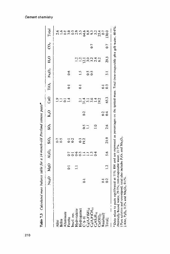
1 CD 13 O
Tab
le 7
.3
Cal
cula
ted
mas
s ba
lanc
e ta
ble
for
a 14
-mon
th-o
ld P
ortl
and
cem
ent
past
e*
J
Na 2
O
MgO
A
1 2O
3 S
iO2
SO
3 K
2O
C
aO
TiO
2 F
e 2O
3 H
2O
C
O2
Tot
al
|
Alit
e 0-
7 1.
9 2.
6B
elite
0-
5 L
I 1.
6A
lum
inat
e 0
1 0
1F
erri
te
01
0-7
01
1.4
01
0-6
3.0
Inso
l. re
s.
01
0-2
0-3
Hyd
rota
lcit
e 1.
1 0-
6 1.
2 2.
9H
ydro
garn
et
0-3
0-3
2.1
01
1.5
1.2
5.5
C-S
-H
01
1.1
19.2
0-
5 0-
2 31
.4
12.1
64
.6C
4(A
,F)S
H12
1.
1 1.
1 3.
1 0-
5 3.
0 8.
8C
4(A
,F)C
Hn
1.3
3.6
0-5
3.2
0-7
9.3
C6A
S3H
32
0-4
1.0
1.4
2.4
5.2
Ca(
OH
) 2
19.2
6.
2 25
.4R
esid
ualf
0
1 0-
2 0
1 0-
7T
otal
} 0-
2 1.
2 5.
6 21
.0
2.6
0-4
65.3
0-
3 3.
1 29
.3
0-7
1300
*Dat
a re
late
to
past
e eq
uili
brat
ed a
t 11
% R
H a
nd a
re e
xpre
ssed
as
perc
enta
ges
on t
he i
gnit
ed m
ass.
Tot
al (
non-
evap
orab
le p
lus
gel)
wat
er,
40-6
%;
chem
ical
ly b
ound
wat
er,
29-3
%;
non-
evap
orab
le w
ater
, 21
-7%
.fP
ore
solu
tion
and
una
ssig
ned;
tot
al a
lso
incl
udes
P2O
5 an
d M
n 2O
3.
{Als
o, P
2O
5,
0-2%
and
Mn 2
O3,
01
%.

Hydration of Portland cement
Table 7-4 TG data and water contents for phases in Portland cement pastes*
Temp. (c
5075
100125150
175200225250300
350400450500550
600700800900
Data forTotalf11% RHD-dried
Phase and mass of water retained at
C) C-S-H
(0-643)(0-514)(0-418)0-3150-263
0-2150-1860-1670-1480119
0-0870-058004500320022
0016001300100006
CH
0-3210-3210-3210-3210-321
0-3210-3210-3210-3210-321
0-3210-3050-24700220006
0-003000200010000
AFm
0-9640-9000-7580-7320-704
0-6710-5140-4790-4470-286
0-2540-231019301290096
0-084004500100003
standard drying conditions0-739J0-3860-273
0-3210-3210-321
0-9640-9640-643
AFt
1-6711-4460-9640-6260-427
0-3860-3370-2920-2440-177
01380116010300900-077
0-0710-02200130000
1-7131-7130-386
given temperature^
Hgt§
0-5650-5650-5650-5650-565
0-5650-5650-3210-1610129
00960064004800320026
0016000000000000
0-5650-5650-565
Htc||
1115110510340-9920-908
0-8300-7570-7490-7360-702
0-5340120005500370016
0010000500000000
111510670-830
co2**
Any
100010001000
toooI 000
L-00010001000I-000L-000
10001000100010001000
10000-80000000000
100010001000
*TG with heating rate lOKmin l, 50 mg specimen, flow rate of dry N2,f Non-evaporable and gel water.\ Of uncertain significance for w/c < 0-4.§ Hydrogarnet-type product from ferrite phase.f̂ Grams retained per gram of CaO present in the given phase, except for the hydrotalcite-
type phase, for which it is grams per gram of MgO present in that phase.** Fraction of the CO2 retained, irrespective of the phase in which it is present.|| Hydrotalcite-type phase.
In most cases, they are given as mass ratios of H2O to CaO, so that, inorder to calculate the amount of H2O in a given phase at a particulartemperature, it is necessary only to multiply the mass of CaO present inthat phase by the relevant entry in the table. By summing the quantitiesof volatiles retained by each of the phases at each temperature, asimulated TG curve is obtained. The data points in Fig. 7.5 werecalculated by this procedure using the data in Table 7.3, and thecontinuous curve was obtained experimentally for the paste to whichthose data relate. It is thus possible to account for the general form of theobserved curve. The level of agreement between observed and calculated
211

Cement chemistry
curves is limited by several factors, including uncertainties and approxi-mations in the reference data, the poor crystallinity of most of thehydrated phases and their intimate admixture with each other. Table 7.4also contains data for the three definitions of the water content describedin Section 5.2.2 and Table 7.3 includes the values obtained for theexample given.
7.5 Calorimetry, pore solutions and energetics7.5.7 The early and middle periodsFigure 7.7 shows the heat evolution curve for a typical Portand cementpaste, determined by conduction calorimetry. It broadly resembles thosegiven by C3S (Fig. 5.14), and comparison with the microstructuralevidence (Section 7.2) shows that it can largely be explained in a similarway. The initial peak (1) is attributable to a combination of exothermicwetting and the early-stage reactions, which with cement give a gelatinouscoating and rods of AFt phase. Rehydration of hemihydrate to givegypsum may contribute. The main peak (2) corresponds to the middle-stage reaction, in which the main products, as with C3S, are C-S-H andCH. The gradually decreasing rate of heat evolution after 24 h cor-responds to the continuing slow reactions of the late stage, which againgive mainly C-S-H and CH. As with C3S, the process may be dividedinto the five stages of initial reaction, induction, acceleratory anddeceleratory periods, and the final period of slow reaction.
Many cements show a shoulder or more definite peak (3) at about 16 h.This has often been associated with the replacement of AFt by AFmphase, but comparison with the microstructural evidence shows that thisis incorrect (P32); it is associated with renewed formation of ettringite.A further, less distinct shoulder (4) has been associated with hydration ofthe ferrite phase (P32) or conversion of AFt to AFm phase (S37). It may
10 5020 30 40TIME (HOURS)
Fig. 7.7 Rate of heat evolution at 20° C for a typical Portland cement; for signifi-cance of numbered peaks, see text. After P32.
212

Hydration of Portland cement
correspond to a peak at about 50 h observed by Stein (S85). In all thesereactions involving the aluminate or ferrite phases, the principal exo-thermic component is probably the reaction of the anhydrous compoundwith water and not the precipitation or subsequent reactions of hydratedcompounds.
Many studies of concentrations in the pore solution during theearly and middle periods have been reported (G63,L35,L36,T44,U13).Figure 7.8 shows typical results. Relatively high concentrations of Ca2+,K+, Na+, SO^~ and OH" are quickly reached. Between 2 and 12 h in theexample given, the concentrations change relatively little, indicating anapproximate balance between the continued dissolution of the cementphases and the precipitation of products. At 12—16h, the concentrationsof Ca2+ and SO^" fall sharply, and the solution thereafter is essentiallyone of alkali hydroxides. The sharp fall at 12-16 h corresponds to therenewed growth of ettringite observed in the SEM and to shoulder (3) onthe heat evolution curve. Concentrations of SiO2 and A12O3 are lowthroughout, values of 003-005mmoll~1 for Si and below 5ppm for Alhaving been reported for times from 20 s to 45min (T44).
Any more detailed interpretation demands that both activity coeffi-cients and the existence of complex species be taken into account(B98,G63). Gartner et al (G63) showed that, for most cements, the
~ 60
T I M E10(HOURS)
Fig. 7.8 Concentrations in the pore solution (scaled as indicated in the cases ofOH~ and SiC>2) of a Portland cement paste of w/c ratio 0-5. After L35.
213

Cement chemistry
solution is saturated in CH within 12min and that the saturation factor(defined as the activity product divided by its value at saturation) reachesa maximum of 2-3 within 2 h. For gypsum, saturation is reached within6min, but the saturation factor never exceeded 1-3 in the cases studied.With cements high in K2O, the solution can become saturated insyngenite. Gartner et ah found that the K+ and Na+ concentrationsincreased rapidly during the first 12min and only slowly, or not at all,during the subsequent period up to 3 h.
One may calculate a partial mass balance for the reaction at an age of30min. QXDA of a typical cement retarded with gypsum showed that, atthis age, 11% of the aluminate and 8% of the ferrite phase had reacted(T35). Assuming from the bulk analysis that the cement contained 12%of aluminate and 7% of ferrite, and that these phases had the typicalcompositions given in Table 1.2, a total of 1-Og of CaO and 0-5 g ofA12O3 are released from them per 100 g of cement. For broadly similarcements at the same age, ettringite contents of about 2% have beentypically reported (B115,U14). These appear to be referred to masses ofpaste, and suggest values of about 3% referred to that of cement. Thisquantity of ettringite, ignoring any iron substitution, contains 0-8 g ofCaO, 0-2 g of A12O3 and 0-6 g of SO3. It thus appears that, of the A12O3
released, less than half enters the ettringite. Apart from small amounts insolution, the remainder and the CaO, SiO2 and part of the SO3 releasedfrom other phases presumably enter the amorphous gel that is alsoformed.
The evidence from microstructure, calorimetry and other sourcessuggests that the hydration processes of cement and C3S are essentiallysimilar. There are important differences in the nature of the early productand in where the C-S-H formed in the middle stage of reaction begins todeposit, but in both cases it would appear that the early reaction slowsdown because of the deposition of a layer of product, which eitherisolates parts of the anhydrous surfaces from the main solution or allowsthe concentrations close to those surfaces to rise to values approachingthe theoretical solubilities of the anhydrous compounds. In both cases,the initiation of the main reaction and the kinetics in its acceleratoryphase appear to be controlled by the nucleation and growth of C-S-H.
7.5.2 Pore solutions after the first dayApparatus for extracting pore solution from hardened cement pastes byapplying pressures of some 375 MPa was first described by Longuet et al.(L37), and many other investigators have reported analyses of solutionsthus obtained (e.g. D43,X1); for further references see T43). With pastesof normal Portland cements more than about 1 day old, the only ionspresent in concentrations above a few mmoll"1 are K+ , Na+ and OH~.Most studies show the concentrations of these ions to rise with time, andto approach a limit after 28-90 days. Some show concentrations passingthrough maxima, with subsequent decreases that are usually slight.Typical concentrations after 180 days for pastes of w/c ratio 0-5 are0-08moll"1 for Na+ and 0-24moll"1 for K+ for a low-alkali cement (XI)
214

Hydration of Portland cement
and (Memoir1 for Na+ and 0-55molT1 for K+ for a high-alkali cement(L37). The corresponding OH~ concentrations are 0-32moll"1 and0-71 moll"1 respectively. Differing views have been expressed as to thevalidity of the method, mainly because of the possibility that highconcentration gradients exist (e.g. D44, L38).
The K+ and Na+ are present in the cement partly as sulfates and partlyin the major clinker phases (Section 3.5.7). When the phases containingthem react, the accompanying anions enter products of low solubility andequivalent quantities of OH~ are produced. The K+, Na+ and OH~ ionsare partitioned between the pore solution and the hydration products.Some estimates of the fractions remaining in solution have been too highbecause non-evaporable water was used as a measure of bound water andthe quantity of pore solution thereby overestimated.
Taylor (T43) described a method for predicting the concentrations atany desired age after 1 day from the w/c ratio and the contents of totalNa2O, total K2O, water-soluble Na2O and water-soluble K2O in thecement. It was assumed that the amount of each alkali cation taken up bethe products is proportional to its concentration in the solution and tothe quantity of products (C-S-H and AFm phase) taking it up. This ledto the equation
c = mv/[V+(bxP)] (7.4)
where c is the concentration in moll"1, mr the quantity in millimoles ofalkali cation released, V the volume of pore solution in ml, P the quantityof relevant products (C-S-H + AFm phase) relative to that formed oncomplete hydration, and b an empirical constant, called the bindingfactor, equal to 200 ml for K+ and to 310 ml for Na+. V was taken to bethe total volume of water less the volume of bound water, i.e. thatretained at 11% RH. The latter quantity, and mT and P, were estimatedusing empirical equations.
For a Portland cement with 0-2% total Na2O and 0-6% total K2O, atw/c = 0-5 and an age of 1 year, calculation by the above method indicatedthat 59% of the Na+ released and 48% of the K+ released were taken upby the products. The ratios of alkali cations to Ca2+ in the products aresufficiently low (typically <001 for Na+ and ~001 for K+) to suggestthat the ions, with an equivalent quantity of OH~, are adsorbed. AsGlasser and Marr (G72) concluded earlier, Na+ appears to be morestrongly held than K+. As noted in Section 7.4.3, the ratios of alkalications to calcium found in the cement gel by X-ray microanalysis arehigher than those in the solid products, because they include the materialsdissolved in the pore solution, which are deposited when the latterevaporates.
7.5.3 Energetics of cement hydrationCopeland et al. (C45) reviewed the energetics of cement hydration. Afterthe first few days, the rate of heat liberation is too low for conductioncalorimetry to be a practicable means of investigation, but the totalamount of heat liberated after any desired time can be determined from
215

Cement chemistry
f 500CXI
£400
£ 300
= 200
UJ21 mn
i i
Type
I I
III—^ —3gzzfr
- ° ^ : f y p e I
TypelV^o--0
-
1 l 1
3 7 28 90DAYSAGE (LOG
1 6-5 13- - Y E A R S - -
SCALE)Fig. 7.9 Average cumulative heat evolution for a total of 20 Portland cements ofASTM Types I, II, III and IV, hydrated at w/c = 0-4 and 21°C. After C45.
the heat of solution in acid, which is compared with that of theunhydrated cement. Figure 7.9 gives average results thus obtained fordifferent ASTM types of Portland cements.
With any Portland cement, the amount of heat evolved by a given timeis directly related to the amounts of the clinker phases that have reacted,and thus depends on such factors as the particle size distribution, w/cratio and temperature and RH of curing. As the results in Fig. 7.9 show,it also depends on the cement composition. At all ages, the amount ofheat liberated is greatest for the Type III (high early strength) cementsand least for the Type IV (low heat) cements. The differences reflect thedifferent average potential phase compositions, which show progressivelylower contents of C3S and C3A, and progressively higher ones of C2S,along the sequence from Type III to Type IV.
Using least-squares regression analysis, the heat liberated at any givenage was predicted from the potential phase composition by equations ofthe type
Ht = a(C3S) + b(C2S) + c(C3A) + d(C4AF) (7.5)
where Ht is the amount of heat evolved in kJkg"1, the formulae denotethe mass fractions of the phases calculated by the Bogue equations andthe coefficients a, b, c and d have the values given in Table 7.5, which alsoincludes values for the enthalpies of hydration of the pure clinker com-pounds, taken from the data in Sections 5.7.3 and 6.5.5. The agreementbetween the least-squares coefficients and the enthalpies of hydration isgood for mature pastes, but there are some anomalies for younger pastes.
In principle, it should be possible to calculate the heat of hydrationfrom the quantitative phase compositions of the unreacted mix and of the
216

Tab
le 7
.5
Coe
ffic
ient
s in
equ
atio
n 7.
5 fo
r pr
edic
ting
the
cum
ulat
ive
heat
evo
luti
on i
n a
cem
ent p
aste
of
give
n ag
e fr
om
the
pote
ntia
l ph
ase
com
posi
tion
of
the
cem
ent
(for
w/c
= 0
4 an
d 21
° C)
(C45
)
Com
poun
d
C3S
P-C
2SC
3AC
4A
F
Coe
ffic
ient
a b c d
3d
243 50 887
289
Val
ue
7d
222 42
1556 494
of t
he c
oeff
icie
nt
28 d
126
105
1377 494
(kJk
g-1
)
90 d
435
176
1301 410
for
age
give
n
lyr
490
226
1167 377
belo
w
6-5
yr
490
222
1372 464
13 y
r
510
247
1356 427
Ent
halp
y of
- co
mpl
ete
hydr
atio
n*(k
Jkg
-1)
-51
7±
13
-26
2—
114
4|;
-167
2J-4
18
§
* F
rom
dat
a in
Cha
pter
s 5
and
6.t
Rea
ctio
n w
ith g
ypsu
m t
o gi
ve C
4A
SH
i 2.
\ R
eact
ion
with
gyp
sum
to
give
ett
ring
ite.
§ R
eact
ion
in p
rese
nce
of e
xces
s C
H t
o gi
ve a
hyd
roga
rnet
.
Q o a 1 CD

Cement chemistry
paste, using standard enthalpies of formation. The sensitivity of suchcalculations to small errors in the latter data probably renders thisapproach unsatisfactory with existing data.
7.6 Actions of calcium sulfate and of alkalis7.6.1 SettingSetting times are commonly defined empirically, using a Vicat needle.In this device, weighted needles of standard design are allowed to sinkinto the paste, and initial and final set defined as the times when thedegree of penetration falls below specified levels. In the British standard,which is typical, initial set must occur not earlier than 60 min (45 min forthe highest strength classes).
In contrast to some earlier observations (L36,L39,O20), Tang andGartner (T35) found that the amounts of both aluminate and ferritephases reacting during the first 30 min were substantially decreased inpresence of gypsum or other forms of calcium sulfate, and evidence fromXRD, DTA, IR spectroscopy, conduction calorimetry and SEM showsthat setting occurs during the acceleratory period and thus correspondsto a period of rapid formation of C-S-H and CH (B116). Themicrostructural evidence (Section 7.2.3) shows that little change occursin the amount or morphology of the ettringite during this period, thesecondary growth of ettringite occurring later. The concept of a cohesionpoint, at which the shells surrounding individual cement grains coalesce(D40), further indicates the importance of the relation between C-S-Hformation and both setting and the initial stages of strength development.The close similarity in setting behaviour between pastes of cement andC3S, and the relation between setting and microstructural developmentin C3S pastes, provide further evidence that normal setting dependsprimarily on the silicate reactions.
If too little gypsum is added, or none at all, many cements undergowhat is termed 'flash' or 'quick' set. This is a rapid set, with muchevolution of heat; plasticity is not regained on continued mixing, and thesubsequent development of strength is poor. It is associated withincreased early reaction of the aluminate and ferrite phases (T35), andwith the formation of plates of AFm phase throughout the paste. Thesecan be 5-10/xm in size (L39). The meshwork of plates, which may becontrasted with the much more compact coatings of gel and small rods ofAFt phase formed in the presence of an adequate supply of gypsum,accounts for the rapid stiffening, but the reason for the subsequent poorstrength development is less clear. Possible explanations include theformation during the initial reaction of strongly protective layers ofproduct around the cement grains, and the existence of a microstructureweakened by the large plates of AFm phase. Some cements low inaluminate phase do not show flash set even if no gypsum is added.
Another undesirable condition is called 'false set'. This is also a rapidset, but there is no abnormally high evolution of heat, plasticity isregained on further mixing, and subsequent strength development is notmarkedly affected. The most usual cause of false set is the presence of too
218

Hydration of Portland cement
much calcium sulfate in the form of hemihydrate, which is rehydratedto give gypsum (called 'secondary' gypsum). The setting is attributable tothe interlocking of the gypsum crystals, which are tabular and can be5-10 mm in longest dimension (L39). If the quantity of secondarygypsum is not too great, it redissolves on further mixing, and thereactions then follow their normal course. Dehydration of gypsum tohemihydrate can occur during milling; hemihydrate may also be addeddeliberately, if a more reactive form of calcium sulfate is required. Withcements high in K2O, syngenite can be precipitated; this also can causefalse set, and, due to the removal of CaSO4 from the system, even flashset (J27).
7.6.2 Optimum gypsumThe gypsum in cement affects not only the setting time, but also thestrength development and the volume stability. Locher et al. (L36,L40),Kanare and Gartner (K38) and Tang and Gartner (T35) have discussedfactors governing the optimum content and the effects of varying thesource of the sulfate. The situation is complicated by the fact that,contrary to some early conclusions, the amounts needed to optimizedifferent properties, such as strength at various ages and dryingshrinkage, are not necessarily the same; also, the amount needed tooptimize a given property in a concrete may not be the same as thatrequired in a paste or mortar (K38).
During the early and middle periods of reaction in a cement paste,gypsum or other forms of calcium sulfate dissolve and react at or close tothe surfaces of the clinker grains, or more specifically those of the alumi-nate and ferrite phases. The factor most directly influencing the course ofthe early reactions is not so much the relative amounts of calcium sulfate,aluminate and ferrite phases, as the rates at which the relevant ionicspecies are made available at the surfaces of the cement grains. The ratesat which Ca2+ and SO^" ions are supplied by the calcium sulfate thusdepend both on the amount of the latter and on its physical and chemicalnature. Hemihydrate or 7-CaSO4 supply ions more quickly than doesgypsum, which in turn supplies them more quickly than anhydrite. Othermajor factors affecting the supply of these ions are the particle sizedistribution of the calcium sulfate and the distribution in space of theparticles; Tang and Gartner (T35) found that a given proportion ofgypsum added by intergrinding was much more effective than the sameproportion added by blending, all other conditions being as nearly aspossible equal. Intergrinding presumably brings the gypsum particles intomore intimate contact with those of the clinker. Increase in any of thefactors rendering the CaSO4 more readily available will tend to decreasethe amount that is needed to produce a given effect in the early stage ofreaction. Increase in temperature has a similar effect (C46).
Factors affecting the rate at which A12O3 is supplied include its contentin the clinker, its distribution among the clinker phases and especially theamount present in the aluminate phase, the specific surface area ofthe ground clinker, the reactivities of the aluminate and ferrite, and the
219

Cement chemistry
microstructure of the clinker particles, or, more specifically, the areas ofsurface composed of aluminate and ferrite phases and the manner inwhich these phases are intergrown with each other and with the silicatephases. Any factor increasing the availability of the A12O3 will tend toincrease the amount of gypsum that is required to produce a given effectin the early reactions.
Sulfate ion is also supplied by the clinker, especially as alkali sulfates orcalcium langbeinite, and Ca2+ ions are supplied by the clinker phases,including free lime. The alkali sulfates provide a highly available sourceof SO4", but the alkali cations, or more probably the OH" ions that theyproduce, have additional effects (Section 7.6.3).
The minimum content of SO3 required to control setting is typicallyaround 2%. Increase in SO3 content beyond the minimum required haslittle effect on setting unless the proportion of hemihydrate or 7-CaSO4 isso high as to cause false set. It causes a progressive decrease in theshrinkage that occurs in dry atmospheres (e.g. at 50% RH) and aprogressive increase in the expansion that occurs in water. If expan-sion is excessive, the concrete disintegrates; this limits the permissibleSO3 content, which, in typical specifications, is set at 2-5-4-5%. The SO3
content above which damaging expansion is liable to occur depends oncement composition and fineness, but seems rarely to be under 5-6%(H45,H46,L41,T45).
For any particular clinker and source of SO3 there is an optimumcontent of SO3 for strength at early ages. In a careful study, in whichstrengths were corrected empirically for the effects of differing particlesize distributions and contents of entrapped air, Osbaeck and Jons (O9)found maximum 1-day strengths at 3-5% SO3 for a number of cementshaving different alkali contents and clinker SO3/alkali ratios. At laterages, somewhat variable results have been reported; in general, theoptimum seems to shift to higher values but to become less pronounced.The results of Osbaeck and Jons, and of Jelenic et al. (J28), indicate thatit is more definitely upwards if the alkali content is high. In evaluating theeffect of gypsum content on strength or other properties, it is necessary toensure that other relevant factors are as far as possible kept constant.Thus, if cements with the same clinker but different gypsum contents areground to the same specific surface area, the clinker will be less finelyground the more gypsum is present, and this will tend to decrease the rateof strength development.
Calcium sulfate additions probably affect both the quantities ofproducts that are formed, especially at early ages, and the microstructureat all ages. Addition of CaSO4 is reported to increase the rate of hydra-tion, both of pure C3S and of the alite in cement (B117,C46,J28,J29,L39).This could explain an increase in strength at early ages due to additionsbelow the optimum, but not a decrease with larger amounts. The fact thatcalcium sulfate additions affect the drying shrinkage also suggests thatthe microstructure is modified. This could occur in various ways, e.g. bychanges in the micromorphology of the C-S-H or by incipient precipi-tation of ettringite throughout the gel. The latter effect, if it happened at
220

Hydration of Portland cement
an early age or to a limited extent, could augment strength through adecrease in porosity, but if it happened later or to too large an extentcould decrease strength through localized expansions.
Attempts to formulate equations relating optimum gypsum content tocomposition and particle size distribution have proved of little practicalvalue, and gypsum contents are normally decided on the basis of empiricalstrength tests. In practice, the molar ratios of total SO3 to total A12O3 inmodern cements range from 0-5 to 0-9, with an average of about 0-6 (K38).In order to adjust the supply of SO^ to that required at different stages ofthe hydration process, it may be desirable to use mixtures of differentforms of calcium sulfate; for example, with cements high in aluminatephase, a mixture of anhydrite and hemihydrate, the latter produced bydehydrating gypsum during milling, has been recommended (L39).
7.6.3 Effects of alkalisAlkali cations normally occur in cements either as sulfates or in the majorclinker phases. In either case, the balancing anion sooner or later enters ahydration product of low solubility, and an equivalent amount of OH~ion is released. Apart from syngenite precipitation, mentioned above, theeffects of alkali cations on cement hydration are likely to be predomi-nantly those of the OH~ ion. Jawed and Skalny (J27) reviewed theseeffects, both on the hydration process and on the properties of thehardened product. In general, early strengths are increased and latestrengths decreased. Some other properties, such as drying shrinkage, areaffected, and the optimum gypsum content is increased. This last effectmust be taken into account when effects on strength are considered. Lerch(L41) attributed it to accelerated early reaction of the clinker phases.
The results obtained by Osbaeck and J0ns (O9) in the study mentionedin the previous section are probably typical. They show the effects ofalkali sulfates on early and late strengths and on optimum gypsumcontents mentioned above. The effects on strength were diminished orabsent at gypsum contents above the optimum. QXDA showed that theincreased early strengths were associated with increased reaction ofthe alite, aluminate and ferrite phases. This effect was quite marked; forexample, at 1 day, the reaction of the alite increased from 26% for acement low in soluble alkalis to 56% for an otherwise similar cement highin them. There were less definite indications of an association between thedecreased strength at 28 days and decreased consumption of the clinkerphases, and the authors were uncertain whether the decrease in strengthwas due to this or to the formation of a less favourable microstructure.
Bezjak et dl. (B112) similarly found that the fractions of alite reactingat early ages were substantially increased in the presence of alkali sulfate,both in Portland cement and in mixtures of alite with C3A. After 10 days,which was the longest time studied, the fraction reacting was stillenhanced in presence of alkali sulfate in the case of a cement low inaluminate phase, but was slightly lowered in that of a cement higherin aluminate. Applying a theory of the kinetics of hydration described inSection 7.7.2, they attributed the acceleration at early ages primarily to
221

Cement chemistry
an increase in the permeability of the layer of hydration productssurrounding the alite at a stage soon after the rate of reaction had becomecontrolled by diffusion.
Tang and Gartner (T35) studied a clinker low in alkalis and in SO3, buthigh in aluminate, which they blended with varying mixtures of calciumsulfate, calcium alkali sulfate and alkali sulfate phases. They, too, foundthat alkali sulfates increased the early strength; without exception, the1-day strengths obtained using blends of gypsum or hemihydrate withaphthitalite, syngenite or calcium langbeinite were greater than thoseobtained at the same ratio of total SO3 to A12O3 with the calcium sulfatesalone, calcium langbeinite and syngenite being especially effective. Theefficacy of calcium langbeinite as a set-controlling agent was earlierrecognized by Moir (M12). At 28 days, in contrast to the findings ofOsbaeck and Jons, there was little significant difference in strengthbetween the cements with and without alkali sulfates, though those of theformer tended to be lower.
Jelenic et al. (J29) found that, for pastes of alite and C3A with varyingamounts of gypsum and with or without alkali sulfate, high strengths at28 days were correlated with low C3A consumption at 1 day. The latestrengths were increased, not decreased, in the presence of alkali providedthat the gypsum content was suitably adjusted. Tang and Gartner (T35)similarly found little correlation between the amount of aluminate phaseconsumed at 2 min and the compressive strength at 1 day, but there was anegative correlation between this quantity and the strength at 28 days.They concluded that a reduced initial aluminate consumption tended toimprove not only the workability of the fresh paste, but also the ultimatestrength of the hardened material.
Ramachandran et al. (R39) found that the rate of reaction of C3S atages up to at least 28 days was substantially increased by addition ofNaOH. Strengths were unaffected up to 7 days, but were lowered at 28days. SEM of fracture surfaces showed that the NaOH affected themorphology both of the C-S-H and of the CH.
7.7 Kinetics and modelling of the hydration process7.7.1 Experimental dataThe kinetics of cement hydration are concerned with the relationsbetween the degree of hydration a and the age /, and with the factors thatinfluence them. Curves of a against t will be described as kinetic curves.From the practical standpoint, the kinetic curve controls the way inwhich the physical properties develop as curing proceeds.
a may relate either to an individual clinker phase or to the cement as awhole. Because cement is a mixture of phases that react at different rates,there are problems in determining, and even in defining, a for the wholecement; it is defined here as the mass fraction of the cement that hasreacted, irrespective of phase. In principle, it may be obtained bysumming the amounts of the individual phases that have reacted, whichin turn can be determined by QXDA or in other ways. Because of theexperimental difficulty and questionable precision of this approach, less
222
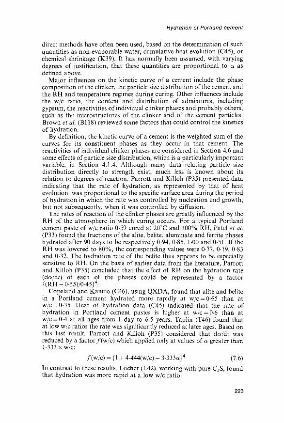
Hydration of Portland cement
direct methods have often been used, based on the determination of suchquantities as non-evaporable water, cumulative heat evolution (C45), orchemical shrinkage (K39). It has normally been assumed, with varyingdegrees of justification, that these quantities are proportional to a asdenned above.
Major influences on the kinetic curve of a cement include the phasecomposition of the clinker, the particle size distribution of the cement andthe RH and temperature regimes during curing. Other influences includethe w/c ratio, the content and distribution of admixtures, includinggypsum, the reactivities of individual clinker phases and probably others,such as the microstructures of the clinker and of the cement particles.Brown et al. (Bl 18) reviewed some factors that could control the kineticsof hydration.
By definition, the kinetic curve of a cement is the weighted sum of thecurves for its constituent phases as they occur in that cement. Thereactivities of individual clinker phases are considered in Section 4.6 andsome effects of particle size distribution, which is a particularly importantvariable, in Section 4.1.4. Although many data relating particle sizedistribution directly to strength exist, much less is known about itsrelation to degrees of reaction. Parrott and Killoh (P35) presented dataindicating that the rate of hydration, as represented by that of heatevolution, was proportional to the specific surface area during the periodof hydration in which the rate was controlled by nucleation and growth,but not subsequently, when it was controlled by diffusion.
The rates of reaction of the clinker phases are greatly influenced by theRH of the atmosphere in which curing occurs. For a typical Portlandcement paste of w/c ratio 0-59 cured at 20°C and 100% RH, Patel et al.(P33) found the fractions of the alite, belite, aluminate and ferrite phaseshydrated after 90 days to be respectively 0-94, 0-85, 1-00 and 0-51. If theRH was lowered to 80%, the corresponding values were 0-77, 019, 0-83and 0-32. The hydration rate of the belite thus appears to be especiallysensitive to RH. On the basis of earlier data from the literature, Parrottand Killoh (P35) concluded that the effect of RH on the hydration rate(da/dt) of each of the phases could be represented by a factor{(RH-0-55)/0-45}4.
Copeland and Kantro (C46), using QXDA, found that alite and belitein a Portland cement hydrated more rapidly at w/c = 0-65 than atw/c = 0-35. Heat of hydration data (C45) indicated that the rate ofhydration in Portland cement pastes is higher at w/c = 0-6 than atw/c = 0-4 at all ages from 1 day to 6-5 years. Taplin (T46) found thatat low w/c ratios the rate was significantly reduced at later ages. Based onthis last result, Parrott and Killoh (P35) considered that da/dt wasreduced by a factor /(w/c) which applied only at values of a greater than1-333 x w/c:
/(w/c) = {1 + 4444(w/c) - 3-333a}4 (7.6)
In contrast to these results, Locher (L42), working with pure C3S, foundthat hydration was more rapid at a low w/c ratio.
223

Cement chemistry
Temperature has a large effect, especially in the earlier stages ofhydration; for example, from QXDA, Copeland and Kantro (C46) foundthat in a Portland cement paste of w/c = 0-57, the fraction of thealite hydrated at 2 days was 0-28 at 5°C, 0-63 at 25°C and 0-81 at50°C. Apparent energies of activation calculated from such data were41kJmor 1 at a = 0-6 and 26kJmol"1 at a = 0-7; for belite, a value of56kJmol~1 at a — 04 was obtained. The decrease in the apparent energyof activation in the case of alite was attributed to a gradual change in ratecontrol from a chemical process to diffusion.
7.7.2 Interpretation of kinetic dataThe kinetics of cement hydration are dominated by the effects associatedwith the particle size distribution of the starting material, and attempts toexplain them in which this is ignored can lead to very misleading results(B112,B119,J30,K40-K42,T47). Even laboratory-prepared samples withclose distributions (e.g. 2-5 /xm; K21) are far from monodisperse from thekinetic standpoint. Two approaches to the resulting problems ofinterpretation will be considered.
Bezjak, Jelenic and co-workers (B112,B119,J30) assumed that duringthe hydration of each particle, up to three processes were rate-controllingat different stages. The first was nucleation and growth of a product. Thesecond was a process occurring at a phase boundary. The third was adiffusion process. Each supplanted a predecessor when it became theslowest of the three, at a time that depended on the initial radius r ofthe particle; more than one rate-determining process could thus operatesimultaneously. Given the rate equations and appropriate rate constants,it was possible to calculate the value of a at any desired time for a particleof given radius, and, by summing the amounts of material that hadhydrated for particles of all sizes, the value of a for the whole material.
In the rate equations relating a to t for a single particle, the first did notinvolve r. In the second, a function of a was proportional to (t - to)/r,where t0 is the time at which the process became rate-determining. In thethird, a function of a was proportional to (/ — to)/r2. Kinetics representedby equations of the second and third of these types are described as linearand parabolic, respectively. It was shown that the kinetic curves of anumber of alite and cement pastes, some of which contained added alkalisulfates, could be satisfactorily explained (Bl 19). For the cements,diffusion became virtually the sole rate-controlling process at values of avarying between about 30% and 60%. This appears to agree broadly withthe evidence from apparent energies of activation noted in the previoussection.
Knudsen (K40-K42) assumed that the rate equation relating a to t fora single particle could be either linear or parabolic. Like Bezjak et ai, healso assumed that the total amount of material reacted was the sum ofthe amounts calculated for all the individual particles, and thus, given therate equation for a single particle, the rate constant and the particle sizedistribution, obtained the value of a for the whole material. In contrastto Bezjak et ah, he concluded that the results were highly insensitive to
224

Hydration of Portland cement
the precise form of the rate equation, and that all that could beN learnedabout the latter from the kinetic curve was whether it was linear orparabolic, and the value of the rate constant. Using data from varioussources, Knudsen concluded that, for the values of a > 015 to which hismodel was applicable, some cements followed linear kinetics for virtuallythe whole range of values up to a = 1, and others parabolic kinetics.A change from linear to parabolic kinetics could be produced by addingCaCl2, and the possibility of a gradual change from linear to parabolickinetics at high values of a was not excluded. It is not obvious how theconclusion that some cements show linear kinetics throughout can bereconciled with the evidence from apparent energies of activation.
Knudsen's model led to the prediction that, if linear kinetics werefollowed, the age at which 50% of the cement has hydrated is proportionalto the fineness constant r0 (or x0) in the Rosin-Rammler distribution(equation 4.1); for parabolic kinetics, it predicted that this age is propor-tional to 7Q (K43). Evidence was presented in support of this conclusionfor cements considered to follow linear kinetics. The theory did notpredict any relation to the breadth of the particle size distribution, whichis represented by the slope of the Rosin-Rammler curve.
In neither of these approaches is it necessary to specify the rate-controlling step more precisely than is given above. The discussion on thehydration kinetics of C3S pastes (Section 5.8) is probably substantiallyapplicable also to cement pastes. One may speculate that in the theory ofBezjak et al., the nucleation and growth of C-S-H determines the rateuntil the anhydrous phases cannot supply the ions sufficiently quickly.Dissolution of the anhydrous phases then becomes rate-determining untilthe permeability of the layer of product has decreased to a level such thatdiffusion takes over. It would be highly desirable to examine the implica-tions of both theories in the light of the more recent microstructuralevidence (Section 7.2). It would also be desirable to determine whetherKnudsen's more pessimistic conclusion regarding the information thatcan be extracted from the experimental data results from a more realisticappraisal of the precision of the data, or from the differences between hisassumptions and those of Bezjak et al.
225

8 Structure and properties offresh and hardened Portlandcement pastes
8.1 Fresh pastes8.1.1 WorkabilityWorkability is a general, descriptive term that indicates the ease withwhich a concrete can be mixed, transported, placed and compacted to givea uniform material. There is no single measure of it, but various empiricaltests that provide information on particular aspects are widely used. Themost important is the slump test, in which the material is moulded bylifting away a conical container in which it was placed. The subsidence ofthe resulting pat provides a measure of the ability of the material to flowunder its own weight. Neither this nor any of several other empirical teststhat are in use gives results that are simply related to any fundamentalrheological properties. Their main value is for quality control of a givenconcrete mix rather than for the comparison of different mixes.
The workability of a concrete mix is by no means dependent only onthe physical properties of the cement paste it contains, but an under-standing of it requires one of those properties. For some specialist uses inwhich cement is used without an aggregate, the latter are directly relevant.The most important properties are concerned with rheology, and thissection deals primarily with these properties in Portland cement pastes,free from admixtures, prior to setting. From the chemical standpoint, thisperiod comprises that of initial reaction and induction period. From thepractical standpoint, it includes those of mixing, placing and compaction.
8.1.2 Rheology; viscometryThe resistance of a fluid to flow may be considered in terms of the situa-tion existing between two parallel planes, one of which is moving in itsown plane relative to the other. It is assumed that flow is confined to thesingle direction thus defined, and that the velocity varies linearly withdistance in the direction perpendicular to the planes. Liquids of simpleand stable molecular structure generally obey the Newtonian law
T - 7 / X 7 (8.1)
227

Cement chemistry
where r is the shear stress (Pa), 77 is the viscosity (Pa s) and 7 is the shearrate (s"1), equal to the velocity of one surface relative to the other dividedby the distance between them. The resistance to flow at a given tempera-ture and pressure is thus defined by a single constant, the viscosity.
Suspensions show Newtonian behaviour only if there is no long-rangestructure. In varying degrees, many approximate in behaviour to theBingham model, represented by the equation
T = T0 + (JJL X 7) (8.2)
where TO is the yield stress and \i is the plastic viscosity. No flow occursuntil the shear stress exceeds TO. Many more complex variants on thistype of behaviour are possible; the relation between r and 7 may not belinear, and may show hysteresis (Fig. 8.1). The quantity T/7 for a non-Newtonian fluid is called the apparent viscosity. Its value varies with 7and, if hysteresis occurs, with the previous history of the sample.
In many studies on fresh cement pastes, rotational viscometers havebeen used to obtain flow curves in which shear rate is plotted againstshear stress, including hysteresis effects. Work up to 1988 was reviewed ina book (T48) and several shorter articles (H47,L43,S86). There is generalagreement that there is a yield stress below which no flow occurs, but inother respects the results from different investigations vary widely. Banfill
Fig. 8.1 Idealized plots of shear rate 7 against shear stress r for fluids of varioustypes. (A) Newtonian fluid. (B) Bingham fluid. (C) Shear thinning. (D) Shearthickening. (E) Positive hysteresis: 1, 2, 3A thixotropy; 1, 2, 3B rheodestruction.(F) Negative hysteresis with antithixotropy.
228

Structure and properties of Portland cement pastes
and Saunders (B120) concluded that this arose from two competingprocesses: breakdown of a floe structure caused by shear, and building upof structure due to continuing hydration. They considered that flowcurves and hysteresis loops were of very limited value, to be used only inthe clear understanding of their disadvantages. They are probably usefulmainly as a comparative technique.
Tattersall and Banfill (T48) considered the structural breakdown to bepartly irreversible. Because the irreversible breakdown occurs duringmixing, variable results can be obtained if it is not completed beforemeasurements begin. This problem can be avoided by high-shear mixingprior to the rheological investigation, which probably brings the pasteinto a condition similar to that present in a fresh concrete mix.
8.7.3 Oscillatory and controlled-stress rheometryMacroscopic flow inevitably alters the microstructure of the paste, and,while yield stress gives some information on the microstructure of the floc-culated suspension, viscosity data cannot (B121,S87). In order to obtainfurther information from rheology on paste microstructure, it is neces-sary to use methods in which flow is minimized. It is also necessary thatthe experiments should be of sufficiently short duration that continuedhydration does not complicate the results. For adequate interpretaion ofrheological data, these also must be related to data relating to the courseof the chemical reactions.
In an oscillatory rheometer, the strain can be oscillated through a smallbut increasing amplitude according to a sine function, the frequencybeing held constant, and the resulting stress monitored. It is also possibleto hold the strain amplitude constant and to vary the frequency. Theprincipal data obtained from these techniques are a value of the criticalstrain, marking the change from solid- to liquid-like behaviour, and astress modulus G*, which is a complex quantity. Its real and imaginarycomponents are termed the storage modulus G' and loss modulus G",respectively; G' relates to the solid component of the stress, which is inphase with the strain, and G" to the liquid component. Banfill (B121)described an instrument in which a conduction calorimeter was incorpo-rated in order to monitor the hydration reactions. Schultz and Struble(S87) concluded from oscillatory shear studies that pastes lOmin afterhigh-shear mixing showed solid-like behaviour resulting from a floccu-lated microstructure which was maintained so long as the strain did notexceed ~10~4. At larger strains the microstructure was disrupted, givingrise to liquid-like behaviour.
In a controlled-stress rheometer a constant small stress can be applied,and the resulting strain monitored against time during loading and afterthe stress has been removed. Struble and Schultz (S88) found this methodto be more satisfactory than oscillatory rheometry. They used it to studycement pastes 1 min after the completion of high-shear mixing. Lowapplied stress (e.g. 3-4 Pa for w/c 0-50) produced an immediate strain onwhich was superimposed time-dependent creep. When the stress wasremoved, recovery was slow and far from complete. The behaviour under
229

Cement chemistry
load is that of a viscoelastic solid and that during recovery is that of avisccoelastic liquid. At higher applied stresses (e.g. 9Pa) there was noinstantaneous response, the strain increasing almost linearly with timethroughout loading, and there was no recovery when the stress wasremoved. This behaviour is that of a viscous liquid. These results wereexplained by supposing the paste to be a flocculated suspension. A certainminimum stress was required to break down the flocculated microstruc-ture and thus to effect a change from solid-like to liquid-like behaviour.This critical stress was sharply defined, and the values observed werereasonably consistent with the yield stresses obtained from flow curves oroscillatory shear measurements.
Struble and Lei (S89) found that the yield stress could be determinedfrom creep-recovery curves without being exceeded. It was thus possible toobtain values at successively greater ages on a single specimen withoutcausing structural breakdown after each determination. A study continuedto the stage of initial set showed that the latter corresponded to a sharpincrease in yield stress, which occurred at the end of the induction period.
8.1.4 Models of fresh paste structureHelmuth (H47) considered the cement particles in a paste to constitutea single floe, in which, however, there were regions of varying solid con-tent. On shearing, the particles became more uniformly distributed, andthe static floe structure was reformed on standing. Tattersall and Banfill(T48) considered that this model did not sufficiently explain the irrevers-ible nature of the breakdown caused by shearing, and proposed thatduring the initial reaction aggregates of particles already in contact werecoated with a continuous membrane of gel which, if destroyed byshearing, was replaced by separate coatings around each particle, whichwere less effective in binding the particles together.
It is difficult to test such models directly, as neither light nor electronmicroscopy is readily applied, but Uchikawa et al (U15) described amethod of specimen preparation for SEM examination. The paste wasmixed for 3min and, after various times, was placed on the surfaceof a metal sample holder already cooled in liquid N2. The sample holderwas then further cooled by immersion in liquid N2 and the specimen wasexamined at — 120°C. For a Portland cement paste without admixtures5 min after mixing, floes of small particles and of large particles withadhering small ones were observed, but there was no continuousfloe structure. The average distance between floes was about 3 /xm. At2 h, C-S-H and ettringite were observed on the grain surfaces and thefloes were more definite. At 6h, the layers of hydration products weremuch thicker and a three-dimensional structure was formed through thelinking of the larger grains through smaller ones.
To an extent that increases with the w/c ratio, fresh cement pastesexhibit the phenomenon of bleeding, i.e. settlement of the solid particles.The interparticle attractions are sufficiently strong that particles of allsizes settle at the same rate, typically about 2/xms~l. Settlement tends toincrease the w/c ratio at the top and to decrease it at the bottom of the
230

Structure and properties of Portland cement pastes
sample. It decreases with increased fineness or increased early hydrationrate of the cement. In a concrete, it can produce layers of water beneathaggregate particles or reinforcing bars.
8.2 Hardened cement pastes: models of structure8.2.1 The Powers-Brownyard modelThe rest of this chapter deals with hardened Portland cement paste (hep),which has the properties of a rigid gel. It is a relatively rigid and strongsolid of high porosity and internal surface area. Variations in the relativehumidity (RH) of the surrounding atmosphere cause it to gain or losewater and also produce small but important changes in volume. Powersand Brownyard (P20) described the broad structure of the material by amodel based largely on evidence from total and non-evaporable watercontents and water vapour sorption isotherms. Powers later modified themodel in minor respects (P36).
In this model, hep is assumed in the general case to comprise threecomponents from the volumetric standpoint, viz. (a) unreacted cement,(b) hydration product and (c) capillary pores. Individual solid phases arenot considered, whether in the cement or in its hydration products, whichwere collectively called 'cement gel'. This term may be found confusing,because it includes the CH, which forms relatively large crystals andcannot reasonably be considered part of a gel; the term 'hydrationproduct' is substituted here. The water present in the paste was categor-ized as evaporable or non-evaporable, the latter being defined in the laterwork (P36) as that retained on D-drying. Evaporable water, when pres-ent, was considered to reside partly in the capillary pores and partly in so-called gel pores within the hydration product. This latter part was calledgel water.
The content of non-evaporable water, relative to that in a fullyhydrated paste of the same cement, was used as a measure of the degreeof hydration. Portland cement paste takes up additional water during wetcuring, so that its total water content in a saturated, surface dry conditionexceeds the initial w/c ratio. Evidence from water vapour sorption iso-therms indicated that the properties of the hydration product that weretreated by the model were substantially independent of w/c and degreeof hydration, and only slightly dependent on the characteristics of theindividual cement. The hydration product was thus considered to have afixed content of non-evaporable water and a fixed volume fraction,around 0-28, of gel pores.
The hydration product occupies more space than the cement fromwhich it is formed,, and the capillary pores were regarded as the remnantsof the initially water-filled space. Their volume thus decreases, and that ofthe gel pores increases, as hydration proceeds. Evidence from watervapour sorption isotherms indicated that the hydration product wascomposed of solid units having a size of about 14 nm, with gel pores some2nm across (P36). The width of the capillary pores could not be deter-mined from the available data, but they were considered to be generallymuch wider than the gel pores, though tending to become narrower as the
231

Cement chemistry
water-filled space was used up, and thus in some regions indistinguishablefrom gel pores.
The following symbols are used here.
w/c = initial water/cement ratio, corrected for bleeding.w/c* = critical value of w/c below which complete hydration cannot
occur, typically about 0-38.wt/c = total water/cement ratio in the saturated, surface dry state.wn/c = ratio of non-evaporable water to cement.we/c = ratio of evaporable water to cement in the saturated, surface
dry state, and equal to wt/c less wn/c.Vc = specific volume of unhydrated cement, typically about
3-17 x l O - ^ k g - 1 .Kg = mean specific volume of the gel water, taken here as
100 x l O - ^ k g " 1 .Fn = mean specific volume of the non-evaporable water (m3 kg"1).
Z>w = density of the pore solution in fresh paste, taken here as1000 kg m"3.
mg = mass of gel water per unit mass of cement in a fully hydratedpaste, typically about 0-21.
mn = mass of non-evaporable water per unit mass of cement in a fullyhydrated paste, typically about 0-23.
a = mass fraction of cement hydrated.^max = maximum value of a possible at w/c< w/c*.
8.2.2 Minimum water/cement ratio for complete hydration;chemical shrinkage
Powers and Brownyard (P20) determined the non-evaporable and totalwater contents of pastes of many cements made up at different w/c ratiosand cured for different lengths of time. In Fig. 8.2 the ratios of evaporablewater to cement in saturated, mature pastes of a typical cement areplotted against those of total water to cement. The initial w/c ratios areshown by the scale at the top; up to about 006 kg of water per kg ofcement is taken up during wet curing. The data show a distinct break atw/c = 0-38, and are fitted by the equations
we/c = wt/c - 0-227 for w/c > 0-38 (8.3)we/c = 0482 x wt/c for w/c < 0-38 (8.4)
The value of wt/c at the break is 044.Similar results were obtained for other Portland cements. In the
following interpretation of them, the small changes in total paste volumethat occur during curing are ignored, and any air entrapped or delib-erately introduced during mixing is regarded as being outside the system.Because the hydration product was considered to occupy more spacethan the cement from which it is formed, and since the total volume of thepaste scarcely changes on hydration, complete hydration cannot occur ifw/c is below a certain value. For the cement under discussion, this valueis 0-38, and a mature paste of this w/c ratio consists entirely of hydration
232

Structure and properties of Portland cement pastes
0 - 6 -I I I I I I i
I I / I I I I I
0-8
Fig. 8.2 Relations between the initial (w/c), total (wt/c) and evaporable (wejc)water I cement ratios for saturated, mature pastes of a Portland cement. After P36.
product. The latter contains, per kg of cement, 0-227 kg of non-evaporable water and, in the saturated condition, 0-211 kg of gel water,making a total of 0-438 kg. The pastes with w/c < 0-38 consist ofunreacted cement and hydration product, and thus have (we/c)/(wt/c)equal to 0-211/0-438, or 0-482. The pastes with w/c>0-38 consist ofhydration product and capillary pores, which in the saturated conditionare filled with water, and thus have we/c equal to wt/c - wn/c.
Most investigators appear to have agreed with the observation thatcomplete hydration cannot occur if w/c is below a value in the region of0-38, but Rossler and Odler (R40) reported that hydration was completein a paste with w/c = 0-22, and further investigation may be required. Onthe Powers-Brownyard theory, the value of the minimum depends on thevolume ratio of hydration product to cement, which in turn depends onthe gel porosity of the hydration product. It was assumed that thisporosity was fixed by the inability of new particles to nucleate in poressmaller than a certain size and by that of existing particles to growbeyond a certain size.
If a paste having w/c < 0-44 is cured under sealed conditions, there willbe insufficient water to fill the gel pores completely, and the capillarypores will be empty. The effective RH will be low, and hydration willbecome very slow or stop, even though free space remains. This phenom-enon is called self-desiccation. Even at higher w/c ratios under sealedconditions, partial emptying of the capillary pores will retard hydration,and can produce irreversible changes in pore structure which reduce the
233

Cement chemistry
final strength. It is therefore important to provide an adequate supply ofwater during curing. If a paste is kept in contact with an excess of waterduring curing, the total volume of paste and water decreases. This effect iscalled chemical shrinkage, and may be used to follow the course ofhydration. For this purpose, it has the merits that hydration need not bestopped and that the determination can readily be automated. Knudsenand Geiker (K39) described a device for automated determination on upto 30 samples.
8.2.3 Calculation of volumetric quantitiesThis section gives expressions and values for some important volumetricquantities. The data for the cement discussed in the previous section areadopted as typical.
(1) The total volume of paste per unit mass of cement is Vc + (w/c)/Z)w,where Vc is the specific volume of the cement and Dw the densityof the pore solution in the fresh paste. Assuming a value of3-17 x l O - ^ k g " 1 for Vc and one of 1000 kgm~3 for Dw, thisgives 3-17 x 10~4 +(w/c)/1000 m3 kg"1.
(2) The volume of hydration product per unit mass of cement reactedis obtained by considering the special case of a fully hydratedpaste having the critical w/c ratio, w/c*, in which only hydra-tion product is present; it is Vc -f (w/c*)/Z)w. For the generalcase, it is thus [Kc + (w/c*)/Z)w] xa , where a is the degree ofhydration. Inserting the values of Vc, w/c* and Z)w, this gives7-0 x 10~ 4 xam 3 kg- 1 .
(3) The volume of unreacted cement per unit mass of cement isVc x (1 -a), or 3-17 xlO~4x (1 - a ) m 3 kg"1.
(4) The specific volume of the non-evaporable water Vn is obtained bytaking the volume of hydration product less those of the cementfrom which it was formed and the gel water, and dividing by themass of non-evaporable water. This gives [(w/c*)/Dw - Vgmg]/mn,or 0-74 x 10-3m3kg-1 .
(5) The maximum degree of hydration amax for a paste with w/c < w/c*may be calculated by equating the total volume of paste to thesum of the volumes of unreacted cement and hydration product;it is (w/c)/(w/c*), or (w/c)/0-38. This assumes that an unrestrictedsupply of water is available during curing. If no such water isavailable, the degree of hydration is limited by the amount ofwater present initially to a maximum value of (w/c)/(mn + rag), or(w/c)/0-44.
(6) The ratio of the volume of hydration product to that of the cementfrom which it is formed may be calculated by dividing the formerquantity by the volume of cement reacted per unit mass ofcement, which is a x VC9 giving 1 + [(w/c*)/(Z)w x Vc)]. This givesa value of 2-20.
(7) The porosity of the hydration product is given by dividingthe volume of gel pores per kg of reacted cement by that of the
234
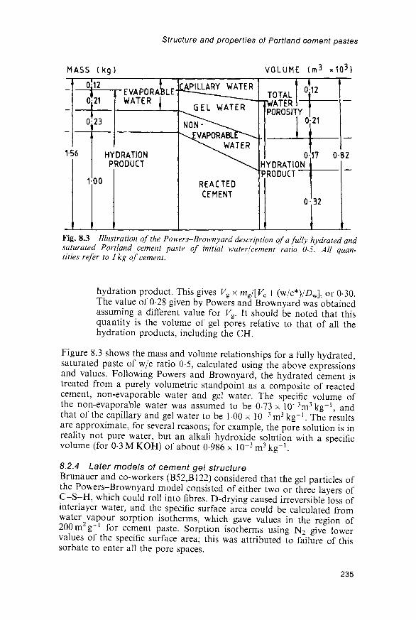
MASS ( k g )
Structure and properties of Portland cement pastes
VOLUME (m3 x1Q3)
1-56
0-21
0 23
'EVAPORAWATER
BLE
HYDRATIONPRODUCT
00
^PILLARY WATER— ^ _
GEL WATER
REACTEDCEMENT
TOTALfATER
POROSITY
012
0-21
HYDRATIONPRODUCT"""
0 32
17 0 82
Fig. 8.3 Illustration of the Powers-Brownyard description of a fully hydrated andsaturated Portland cement paste of initial water/cement ratio 0-5. All quan-tities refer to 1 kg of cement.
hydration product. This gives Vg x mg/[Kc + (w/c*)/Z)w], or 0-30.The value of 0-28 given by Powers and Brownyard was obtainedassuming a different value for Kg. It should be noted that thisquantity is the volume of gel pores relative to that of all thehydration products, including the CH.
Figure 8.3 shows the mass and volume relationships for a fully hydrated,saturated paste of w/c ratio 0-5, calculated using the above expressionsand values. Following Powers and Brownyard, the hydrated cement istreated from a purely volumetric standpoint as a composite of reactedcement, non-evaporable water and gel water. The specific volume ofthe non-evaporable water was assumed to be 0-73 x lO^rr^kg"1, andthat of the capillary and gel water to be 1-00 x 10~3 m3 kg"1. The resultsare approximate, for several reasons; for example, the pore solution is inreality not pure water, but an alkali hydroxide solution with a specificvolume (for 0-3 M KOH) of about 0-986 x 10"3 m3 kg"1.
8.2.4 Later models of cement gel structureBrunauer and co-workers (B52,B122) considered that the gel particles ofthe Powers-Brownyard model consisted of either two or three layers ofC-S-H, which could roll into fibres. D-drying caused irreversible loss ofinterlayer water, and the specific surface area could be calculated fromwater 2vapour sorption isotherms, which gave values in the region of200 m g for cement paste. Sorption isotherms using N2 give lowervalues of the specific surface area; this was attributed to failure of thissorbate to enter all the pore spaces.
235
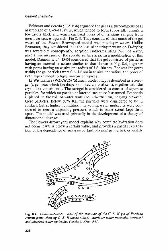
Cement chemistry
Feldman and Sereda (F35,F36) regarded the gel as a three-dimensionalassemblage of C-S-H layers, which tended to form subparallel groups afew layers thick and which enclosed pores of dimensions ranging frominterlayer spaces upwards (Fig 8.4). They considered that much of the gelwater of the Powers-Brownyard model was interlayer water. UnlikeBrunauer, they considered that the loss of interlayer water on D-dryingwas reversible; consequently, sorption isotherms using N2, not water,gave a true measure of the specific surface area. In a modification of thismodel, Daimon et al. (D45) considered that the gel consisted of particleshaving an internal structure similar to that shown in Fig. 8.4, togetherwith pores having an equivalent radius of 1 -6-100 nm. The smaller poreswithin the gel particles were 0-6-1-6 nm in equivalent radius, and pores ofboth types tended to have narrow entrances.
In Wittmann's (W25,W26) 'Munich model', hep is described as a xero-gel (a gel from which the dispersion medium is absent), together with thecrystalline constituents. The xerogel is considered to consist of separateparticles, for which no particular internal structure is assumed. Emphasisis placed on the role of water molecules adsorbed on, or lying between,these particles. Below 50% RH the particles were considered to be incontact, but at higher humidities, intervening water molecules were con-sidered to exert a disjoining pressure, which to some extent kept themapart. The model was used primarily in the development of a theory ofdimensional changes.
The Powers-Brownyard model explains why complete hydration doesnot occur if w/c is below a certain value, and provides a partial explana-tion of the dependence of some important physical properties, especially
Fig. 8.4 Feldman-Sereda model of the structure of the C-S-H gel of Portlandcement paste, showing C-S-H layers (lines), interlayer water molecules (crosses)and adsorbed water molecules (circles). After R41.
236

Structure and properties of Portland cement pastes
compressive strength, on w/c and degree of hydration. No other satisfac-tory explanation of the minimum w/c needed for complete hydrationappears to have been given, and the most important feature of the model isprobably the conclusion that a given volume of cement can react only if anadditional volume of free space approximately 1-2 times as great is avail-able. The direct evidence that the relevant characteristics of the hydrationproduct are independent of w/c and degree of hydration was, however,based largely on data from water vapour sorption isotherms for severelydried pastes, the interpretation of which has been strongly criticised(F17). Further tests of the correctness of the hypothesis are needed.
The Feldman-Sereda model was based on studies of sorption properties,porosities and relations between water content and physical properties.Alone among the proposed models, it is clearly compatible with themicrostructural evidence and with the probable relationships betweenC-S-H gel and crystalline compounds. It is incompatible with that ofBrunauer, but not with the essential features of that of Powers andBrownyard in its original form if the nature of the gel porosity isreinterpreted. Calculations of bound water (Section 7.4.4) indicate thatabout a third of the gel porosity of the Powers-Brownyard model isinterlayer space, the remainder being micro or fine meso porosity* of thekind shown in Fig. 8.4. However, as that figure illustrates, the boundarybetween interlayer space and micropores is ill defined.
The models differ in whether, to what extent, or on what scale the gel isregarded as being composed of separate particles. The microstructuralevidence suggests that the situation differs with the region considered, theouter product being more nearly particulate in nature than the innerproduct. Powers (P36) discussed his model in relation to the meagreevidence on microstructure then available. He recognized that the innerand outer products might differ in microstructure and that the porositiesdefined in the model could be means, but considered that the hydrationproduct would tend towards a uniform porosity. Subsequent progress inthe study of microstructure by electron microscopy and of pore structureby other methods, and in mathematical modelling of microstructure, hasbegun to provide answers to these and similar questions.
8.3 Mathematical modelling of microstructure and properties8.3.1 IntroductionMathematical modelling has the objective of quantifying knowledge ofthe hydration process and microstructure of the resulting material in amanner that permits the prediction of experimentally accessible proper-ties from similarly accessible inputs, thus allowing the effects of changesin inputs or assumptions contained in the model to be examined. Neces-sary inputs comprise such data as the composition and distributions ofsize and shape of the cement grains, w/c ratio and curing conditions, and
*The International Union of Pure and Applied Chemistry has adopted the followingdefinitions of pores by width: micropores, <2nm; mesopores, 2-50 nm; macropores,>50nm.
237

Cement chemistry
typical outputs include mass or volume fractions of phases in a paste orconcrete, content of non-evaporable water, cumulative heat evolutionor physical properties such as strength, porosity or permeability definedin various ways. One can distinguish between fundamental models, whichare based on simulation of the developing microstructure at the levelof individual particles or regions of anhydrous phases, hydration prod-ucts and porosity, and empirical or non-fundamental models, in whichempirical equations play an essential part. Both types have merits andlimitations.
8.3.2 Calculation of porosities and of volume fractionsof solid phases
The calculation of porosities and volumes of phases is an essentialpreliminary stage in the development of most types of model. In thePowers-Brownyard model, the volume of capillary pores per unit mass ofcement is obtained by subtracting the volumes of hydration productand of unhydrated cement from the total volume; using the symbolsdefined in Section 8.2.1, this gives [(w/c) - a(w/c*)]/Z>w. The volume ofgel pores per unit mass of cement is equal t o m g x Vg x a. Expressed asfractions of the total volume, the capillary porosity is [w/c - a(w/c*)]/[(£>w x Vc) + w/c] and the gel porosity is mgFg x a/[Vc + (w/c)/Z)w]. In allthe above expressions, the maximum possible degree of hydration amaX9
equal to (w/c)/(w/c*), must be substituted for a if w/c < w/c*.Powers and Brownyard defined the total porosity as the sum of the
capillary and gel porosities. This definition is adhered to here, but notethat some later workers have used the term 'total porosity' in othersenses. As hydration proceeds, the capillary and total porosities decreaseand the gel porosity increases. Table 8.1 gives some values of the threetypes of porosity obtained from the above formulae, using the data givenin Section 8.2.2 as typical.
In Section 7.4.4, a method is described for calculating the massfractions of each phase in a cement paste. Given the w/c ratio and thedensity of the cement (~3150kgm~3), the total volume of paste may be
Table 8.1 Calculated porosities, based on the Powers-Brownyard model
w/c ratio
0-30-304040-50-50-60-6
Fraction ofcement
hydrated a
0000-79000100000100000100
Capillaryporosity
0490000-560030-610-150-650-24
Gelporosity
0000-270000-290000-260000-23
Totalporosity
0490-270-560-320-610410-65047
238

Tab
le 8
.2
Sat
ura
ted
11%
R
HD
-dry
Ca
lcu
late
d
Ali
te
10
10
10
volu
me
per
cen
tag
es a
nd
poro
siti
es,
Bel
ite
0-6
0-6
0-6
Alu
min
ate
00
00
00
Fer
rite
10
10
10
base
d
Inso
l.re
s.
01
01
01
on p
hase
com
posi
tion a
nd
den
siti
es
C-S
-H
48-7
36-2
27-6
CH
13-9
13-9
13-9
AF
m
11
11
11
8-3
AF
t
3-6
3-6
2-4
Hy
dro
-g
arn
et
2-2
2-2
2-2
Hy
dro
-ta
lcit
e
1-8
1-8
14
Po
res
160
28-5
41 5
CO I ET -t CD Q) CL 3 CD
Cal
cula
ted
for
a 14
-mon
th o
ld p
aste
wit
h w
/c =
0-5
, fr
om t
he m
ass
perc
enta
ges
in T
able
7.3
and
wat
er c
onte
nts
of p
hase
s in
Tab
le 7
.4.
Ass
umed
den
siti
es
3-
(kgm
~3):
ali
te,
3150
; be
lite
, 33
00;
alum
inat
e, 3
060,
fer
rite
, 35
70;
inso
lubl
e re
sidu
e, 2
650;
C-S
-H,
1900
, 21
80,
2700
; C
H,
2240
; A
Fm
, 20
10,
2010
, 24
00;
g'
AF
t, 17
75,
1775
, 238
0; h
ydro
garn
et-t
ype
phas
e, 3
100;
hyd
rota
lcit
e-ty
pe p
hase
, 20
00,
2000
, 230
0. W
here
thr
ee v
alue
s ar
e gi
ven,
the
firs
t is
for
the
sat
urat
ed
o^
stat
e, t
he s
econ
d fo
r m
ater
ial
equi
libr
ated
at
11
% R
H,
and
the
thir
d fo
r D
-dri
ed m
ater
ial.
^J o nT 13 Q.
o CD CD £ CO
CD
O

Cement chemistry
calculated, and using the mass fractions and densities of the phases thevolume of each phase may be obtained. The porosity is then obtained bydifference. This calculation may be performed for any desired dryingcondition, provided the densities and water contents proper to thatcondition are used. Table 8.2 gives the results of such calculations for thepaste to which the data in Table 7.3 relate. The porosities calculated forthe saturated and D-dry conditions are similar to the capillary and totalporosities for mature pastes obtained by the Powers-Brownyard methodand given in Table 8.1.
Figure 8.5 includes porosities derived from calculated phase composi-tions for 18-month-old pastes of a typical Portland cement at varyingw/c ratios and corresponding to (A) the D-dried state, (B) a state thatincludes all bound water, including that present in interlayer spaces, but
0-5 0-6W/C
Fig. 8.5 Relations between porosities (volume percentages) and water/cementratio for mature Portland cement pastes. The experimental data are for pastes atleast 8 months old, and the calculated curves refer to a typical cement aged 18months. Open symbols: total porosities. Solid or half solid symbols: mercuryporosities. Curve A: total porosity. Curve B: free water porosity. Curve C: capillaryporosity. References to data: O (P20); • (S90); A (F37); V (M80); • (S91);A (F38); • (021); V (M80); Q (D46); 3 (H48). In the last two cases,porosities by volume were estimated from data referred in the original sources tomasses of dried paste, assuming the latter to have contained 0-23 kg of water per kgof cement having a specific volume of 3 17 x 10~4 m3 kg~x.
240

Structure and properties of Portland cement pastes
no water in larger pores and (C) capillary porosities, as defined by Powersand Brownyard. Conditions (B) and (C) are possibly realized approxi-mately by taking material not previously exposed to an atmospherebelow saturation and equilibrating it at 11% RH and about 90% RH,respectively (F18,Y5). The porosities defined by condition (B) will becalled free water porosities.
Parrott and Killoh (P35) and Parrott (P37-P39) used a similar pro-cedure and extended it to produce a comprehensive model in whichempirical equations were employed. In essence, it contained three steps,as follows.
(1) The degree of hydration of each clinker phase was calculated at56 ages, using rate equations that took into account the effects oftemperature, RH and w/c ratio (P35). In so far as the clinkerphases were treated separately, the simultaneous existence ofmore than one rate-determining step was assumed. Allowancewas made for the effect of particle size distribution.
(2) The phase composition of the paste by mass and by volume,and the non-evaporable water content, were calculated. Usingthe w/c ratio and densities of phases, porosities were then calcu-lated. Refinements allowed some deviation from the Powers-Brownyard postulate of a fixed volume ratio of gel porosity toC-S-H, and volumes of pores having diameters above andbelow 4nm were calculated separately. The heat evolved wasassumed to be the sum of the amounts given by each clinkerphase, which in turn were assumed to be proportional to thefractions of those phase that had reacted. Extensions of thetreatment permitted the effects of admixture of the cement withflyash to be considered.
(3) The compressive strength, permeability to water and methanolexchange rate were calculated, using empirical equations relatingthem to the porosity.
Typical results for the volume fractions of pores larger than 4nm inmature pastes were approximately 0-26, 016 and 007 for w/c ratios of0-65, 0-50 and 0-35 respectively (P37). For the two higher w/c ratios theseresults are near the capillary porosities of Powers and Brownyard, but forw/c 0-35 the latter value is zero.
Jennings and Tennis (J26) used a procedure broadly similar to thosedescribed above to develop a model with the prime objectives of predictingporosities and specific surface areas determinable by sorption proceduresusing N2. The C-S-H was assumed to be of two types, of which only onewas accessible to N2. Both were assumed accessible to H2O. The massfraction of the C-S-H accessible to N2, and the volumes of the two typesor regions to which the C-S-H was assigned, were obtained using empir-ical equations based on limited sets of experimental data; a constantspecific surface area (392m2 g"1) was assumed for the C-S-H. Theresults were compared with a wider range of data for porosities andspecific surface areas determined using N2.
241

Cement chemistry
8.3.3 Microstructural modelsEarly versions of a fundamental microstructural model of C3S hydration(J31 ,S92) led to a more detailed one due to Garboczi and Bentz (B123 ,G73).In this model, a region of paste was represented by a three-dimensionalarray of pixels. Initially, a given pixel could be assigned to either C3S orwater, the particles of C3S having realistic distributions of size and shape.As hydration proceeded, pixels were removed from the C3S surfaces, andpixels of C-S-H and CH were produced at their expense and that of thepore solution, in proportions that respected the known reaction stoichio-metry and volume relations. The pixels of the product were allowed tomigrate in a random way, subject to rules designed to produce a properrepresentation of the developing microstructure. Tests of the modelincluded comparisons with BSE images and calculations of parametersrelated to the pore structure. The degree of connectivity of each phasecould be calculated; irrespective of w/c ratio, that of the capillary porosityfell rapidly as the latter decreased from 40% to 20%. This conclusionagrees well with the experimental observations described in Section 8.7.Although the model related to pure C3S, it was shown that it should applywithout serious error to cement.
A phase is said to percolate if a continuous path can be tracedthrough it from one side of the system to the other, and the volumefraction at or above which such paths exist is called the percolationthreshold. If the volume fraction is less than this, the phase is entirely inthe form of isolated regions. Brown et al. (B124) summarized percolationtheory more fully. The C3S model (B123,G73) predicted the existence ofpercolation thresholds for capillary pores, C-S-H and CH at about18%, 17-18% and 12-15% respectively. The similarity between thesevalues appears not to be accidental, as values in the region of 16% arefound for a wide range of comparable systems. A single curve was shownto hold for the relation between total capillary porosity and the fractionalconnectivity of the capillary pores, irrespective of w/c ratio. The frac-tional connectivity approximated to 100% at a capillary porosity of 60%.
The degrees of hydration at which the percolation thresholds werereached were also calculated. For a C3S paste with w/c = 0-5, the percola-tion of the capillary pores ceased at about 86% hydration, and those ofC-S-H and CH began at approximately 25% and 55%, respectively.The C-S-H was completely connected by 50% hydration, but thequantity of CH formed was shown to be insufficient to give a fractionalconnectivity above 0-9 even at complete hydration.
Two-dimensional models were also computed, and for given conditionsgave apparent degrees of connectivity much lower than those existing inthree dimensions. Thus, the CH was generally discontinuous in two-dimen-sional sections. This agrees with SEM observations on polished surfaces.
Properties calculated from the model included ionic diffusivities andwater permeabilities (Section 8.7). The model was extended to deal withmortars and concretes, including the microstructure and properties ofthe interfacial zone (Section 12.1.4) and pastes, mortars and concretescontaining silica fume (Section 9.7.2).
242

Structure and properties of Portland cement pastes
8.4 Experimental methods for studying pore structure8.4.1 General pointsThe problems of defining and determining densities of finely poroussolids, indicated in Section 5.2.3, apply to hep. A determination of thedensity of such a material is also one of porosity, since both propertiesare related to the solid volume; the porosity per unit volume of material isequal to 1 — [mJ(Ds x V)], where ms and Ds are, respectively, the massand density of the solid and Fis the total volume. The density and poros-ity determined by any method entailing contact with a fluid can vary withthe extent to which the solid has been dried, how it has been dried and thefluid employed. Fluids may differ in their abilities to penetrate the poresystem, and the pore structure may be altered both during drying and bythe action of the fluid subsequently introduced.
These comments apply also to studies of pore size distribution orspecific surface area, which have been widely studied using sorptionisotherms or, in the former case, mercury intrusion porosimetry (MIP).Gregg and Sing (G74) have described these methods. In both cases, thematerial must first be dried to water contents lower than those likely to beencountered in the normal environment of the material, and the effectscan be serious and difficult to allow for. The amount of water consideredto form part of the solid obviously affects the definition of porosity, butthe extent and manner of drying also affect the pore size distribution.
The most widely used drying procedures have been desorption atordinary temperatures, including D-drying, or at elevated temperatures,and solvent replacement. Freeze drying has also been used (K44). In sol-vent replacement, the specimen, normally in a saturated state, is immersedin an organic liquid such as methanol. The course of replacement can befollowed from the mass change; it has been claimed that all the pore watercan be replaced (D47,P40). The organic liquid is then removed. Because ofthe lower surface tension, one might expect that less damage would occuras the liquid evaporates, and several investigators have concluded that thisis the case (D47,H48,P40). In contrast, Beaudoin (B47,B125) concludedthat straight-chain aliphatic alcohols seriously affect the pore structure,partly through reaction with CH. Methanol and other organic liquidsare retained strongly by cement or C3S pastes, with resulting effects onthe TG and DTA curves (Section 5.1.2). It does not necessarily followthat the pore structure is affected; this applies especially to the coarserpart of the distribution, which is probably the more important for manyof the physical properties.
Porosities have sometimes been reported as percentages by volume ofthe paste and sometimes as volumes per unit mass of dried paste. The firstis the more meaningful, especially as in the latter case the water contentof the material has not always been given. A similar comment applies tospecific surface areas (L44).
8.4.2 Determination of porosities by pyknometryTotal porosities are obtained experimentally from the loss in mass when asaturated paste is D-dried or subjected to some procedure regarded as
243

Cement chemistry
equivalent, such as heating to constant mass at 105°C. Reabsorptionof water by materials thus dried gives identical results (D47). The pro-cedures should be carried out under CO2-free conditions. A value forthe specific volume of the evaporable water must be assumed; this hasusually been 100 x 10~3m3kg~1. Figure 8.5 includes typical values thusobtained.
Powers and Brownyard (P20) found that porosities of D-dried pastesobtained using helium as the pyknometric fluid were lower than thoseobtained using water. Feldman (F37) confirmed this and found that alower value was also obtained using methanol; if a D-dried sample wasexposed to helium, the latter flowed in quickly at first, and then moreslowly. The porosities calculated from the initial, rapidly accepted vol-umes of helium agreed with those obtained with methanol. If the materialwas dried only by equilibration at 11% RH, the porosities obtained withhelium, methanol or saturated aqueous CH were all similar to thoseobtained for D-dried pastes using methanol. For D-dried pastes, theporosities obtained using helium were 23-3%, 34-5%, 42-1% and 53-4%for w/c ratios of 0-4, 0-5, 0-6 and 0-8 respectively. The correspondingvalues obtained with water were 37-8%, 44-8%, 51-0% and 58-7%; theseare included in Fig. 8.5. Day and Marsh (D47) confirmed that porositiesobtained by admitting methanol or propan-2-ol to an oven-dried pastewere substantially lower than total porosities; however, if the undriedpaste was treated with the organic liquid, the volume exchanged wasclosely similar to the total porosity.
Feldman (F37) explained his results in terms of the Feldman-Seredamodel as follows. If the paste is D-dried, water is lost from the interlayerspaces. If the sample is immersed in water, this water is reabsorbed, andthe total porosity therefore includes the volume of the interlayer space.Methanol does not penetrate into this space, and helium does so onlyslowly, so that lower porosities are obtained. If the sample is equilibratedat 11 % RH, the interlayer spaces are largely filled, and the lower value isobtained irrespective of the fluid used. The helium porosities reported byFeldman were near the calculated free water porosities.
8.4.3 Sorption isotherms; specific surface areasSorption isotherms, using water, N2 or other sorbates, have been widelyused to study the pore structure of hep. The results obtained by differentinvestigators show considerable variations, which arise in part fromdifferences in the conditions of preliminary drying.
Desorption of water from a saturated paste at ordinary temperature isa slow process. Figure 8.6 shows results for a fully hydrated C3S paste ofw/c 0-5, in which each point represents the results of a separate experi-ment on a slab 1 mm thick (G75). Loss of water is especially slow at30-80% RH. Parrott and co-workers (P40,P41) similarly found that inthe initial desorption, equilibrium was reached within a few days atRH < 30%, but that at RH values of 40-80% many weeks were needed;there were indications that larger pores emptied through smaller ones.Drying at these humidities led to a coarsening of the pore structure,
244

Structure and properties of Portland cement pastes
DRYING TIME (DAYS)
20 40 60 80 100RELATIVE HUMIDITY (%)
Fig. 8.6 Desorption curves for an initially saturated C3S paste of w/c ratio 0-5,hydratedfor 5-8 years at 25° C in the form of slab samples lmm thick. Each pointrepresents the result of a separate experiment in which the sample was exposed to anatmosphere of given relative humidity for the drying time shown. After G75.
which was indicated by a marked reduction in the specific surface areaaccessible to N2, from over 100m2g~1 at 90% RH to around 30m2g~1 at10% RH, and was also associated with irreversible shrinkage (P42). Onresaturation, the higher surface area was regained, but the pore sizedistribution did not completely revert to that originally found.
Water sorption isotherms for hep show marked hysteresis. Powers andBrownyard (P20) found that, while it was difficult to obtain reproducibledesorption curves, the low-pressure part of the water vapour resorptioncurve varied little with w/c ratio, between different Portland cements, or,if allowance was made for the contents of unreacted cement, with thedegree of hydration. This was their main direct evidence for the con-clusion (Section 8.2.1) that the properties of the hydration productconsidered in their model were essentially independent of these variables.However, the water sorption isotherms obtained by different investiga-tors have varied considerably (e.g. P20,S93), and it is not clear to whatextent the above conclusion would stand had different desorptionconditions been used.
In principle, isotherms at low partial pressures of the sorbate may beused to determine specific surface areas by the Brunauer-Emmet-Teller(BET) method (G74). In this method, it is assumed that molecules of thesorbate are adsorbed on surfaces that can include the walls of pores,provided that the distance between molecules on opposing walls is largecompared with molecular dimensions. From a plot derived from theisotherm, and given the effective cross-sectional area of the sorbate
245

Cement chemistry
molecule, the specific surface area of the sorbent and the net heat ofadsorption are obtained. Using water as sorbate, specific surface areasof about 200 m2 per g of D-dried paste have typically been obtained formature cement pastes of normal w/c ratios (P20,H49); however, much ofthe water has been shown to enter the vacated interlayer spaces, thusrendering the BET equation at best only partially applicable (F35).
Using N2 or other non-polai sorbates, widely varying and usuallymuch lower values have been obtained. Lawrence (L44), reviewing earlierstudies, noted that for well-cured pastes the values ranged from under 10to nearly 150m2g~1, and even higher values, up to 249 m 2 g - 1 , have beenreported (L45). In contrast to values for fully hydrated pastes obtainedusing water, the N2 areas tend strongly to increase with w/c ratio, but arealso much affected by the conditions under which the sample has beendried. It would appear that the value obtained using water, whateverits precise significance, is dominated by the structure at or near theindividual layer level and is thus relatively insensitive to coarser featuresof the structure. The much lower values obtained using N2 may arisethrough inability of the latter to penetrate interlayer spaces; this wouldimply that they can give information about structural features at asomewhat coarser level. Alternatively, based on the model of Jenningsand Tennis (J26), N2 penetrates only one of two types of C-S-H, whichmay correspond to particular regions.
8.4.4 Pore size distributionsThe hysteresis shown by sorption isotherms of hep, whether using water,N2, or other sorbates, indicates the presence of mesopores (G74). Atpartial pressures above those to which the BET theory applies, capillarycondensation occurs. If a liquid forms a meniscus in a cylindrical pore, itsvapour pressure is lowered to an extent that increases with decreasingpore radius. Using an equation due to Kelvin, or other proceduresultimately derived from it, the isotherm may be used to estimate pore sizedistributions in the approximate range of 1-30 nm and may give indica-tions regarding the shapes of the pores. It may be necessary to allow forthe fact that the meniscus forms in a pore narrowed by an adsorbed layerof sorbate. From an early study of this type on D-dried cement pastes,Mikhail et al. (M81) showed that the size distribution of the poresavailable to N2 was probably unimodal and that with increase in w/cfrom 0-35 to 0-7 it shifted to higher values in both the low and the highparts of the distribution. It is difficult to reconcile this conclusion with theunvarying pore size distribution within the gel implied by the model ofPowers and Brownyard.
Lawrence and co-workers (L44,L46,L47) concluded from sorption datausing nitrogen and butane that the microstructure partly collapses duringnormal drying. This agrees with Parrott and co-workers' (P40,P41)conclusion, noted above. Pastes that had been rapidly dried were likely tobe closest in structure to undried pastes; the sorption results indicated thattheir structures were dominated by platey particles or lamellae thatformed slit-shaped mesopores and micropores. Slow drying produced
246

Structure and properties of Portland cement pastes
small pores more nearly cylindrical or /spherical. Methanol treatment atleast partially prevented the microstructural collapse, but did not alwaysproduce an increase in the recorded surface area, though it always causeda change in the shape of the isotherm; this was possibly due to chemi-sorption of the methanol.
Using N2 sorption on samples solvent-dried by methanol exchange,Hansen and Almudaiheem (H48) found the volumes of pores withdiameters smaller than 4 nm and accessible to N2 to be 0-052 ml, 0-035 mland 0-038 ml per g of dry paste for mature pastes of w/c ratio 0-4, 0-6 and0-75 respectively. These results correspond to volume porosities of about9%, 5% and 4% respectively.
Patel et al. (P33) determined the volumes of pores smaller than 4nmor 37 nm in methanol-exchanged samples, using a methanol sorptionmethod in which porous glass granules of known and approximatelymonodisperse pore size were used as a reference standard. Using also thetotal porosity, the volumes in the ranges larger than 4 nm and 37 nm werealso obtained. For a cement paste of w/c 0-59 cured for 90 days at 100%RH, this gave values of approximately 47% for the total porosity, 17%for pores above 4nm, and 12% for pores above 37 nm. For a paste of w/cratio 0-71 cured in the same way, the corresponding values were approxi-mately 57%, 36% and 18%. These results indicate volumes of poresbelow 4nm considerably greater than those reported by Hansen andAlmudaiheem.
Parrott et al. (PI9) used butane sorption to determine the volume ofpores smaller than 50 nm. For a 28-day-old alite paste of w/s 0-59, avolume porosity of 27% was obtained.
8.4.5 Mercury intrusion porosimetry (MIP)This method is based on the fact that a liquid that does not wet a poroussolid will enter its pores only under pressure. If the pores are assumed tobe cylindrical, the pressure p needed to force the liquid into them is givenby the Washburn equation
p = -4j cos 0/d (8.5)
where 7 is the surface energy of the liquid, 9 is the contact angle, and d isthe pore diameter. For Hg, 7 — 0-483 Nm"1 . For 9, values between 117°and 140° have been variously assumed. In a critical review, Good (G76)concluded that, while a case for 180° could be made, it was probably bestto assume one of 130° in the absence of direct experimental data. Themaximum pressure employed is typically around 400 MPa, which allowspores of nominal diameter down to about 3-5 nm to be intruded.
Typical results (Fig. 8.7) show that the distribution moves to smallervalues as hydration proceeds. The observed porosity is mainly in the3-1000 nm range for young pastes, and in the 3-100 nm range for maturepastes. For mature pastes of low w/c ratio, which according to the Powers-Brownyard theory consist entirely of hydration product, nearly all theporosity is below 50 nm (S90). The porosities obtained using mercury at themaximum pressures employed will be referred to as mercury porosities.
247

Cement chemistry
00ooco
cnDU
40
30
20
10
(
_
—
—
°0-
jum)
20Io
•D
•
05
X!
1
3281-5
EQUIVALENT PORE [5 2 H1 i
DAYDAYSDAYS
YEARS
0-5ABSOLUTE
500 2001 1
<¥ JP 7
5
DIAMETER50 20i i
r p J*XT ^
' 150
PRESSURE (MPa)
i (nm)5 2I I
5^
_^I
1
500
Fig. 8.7 Mercury porosimetry curves for a Portland cement paste (w/c ratio 0-47)at various ages. After F38.
Typical values for mature pastes (Fig. 8.5) are somewhat lower than thecalculated free water porosities.
MIP has been very widely used in the study of cement pastes, and theresults obtained by it have been reasonably self-consistent, but it isdoubtful whether the pore-size distributions thus obtained are evenapproximately correct. They may still have some comparativesignificance.
(1) The method does not measure the distribution of pore sizes, butthat of pore-entry sizes (D48). If large pores can be entered onlythrough small pores, they will be registered as small pores.Previous suspicions that this effect is of major significance withcement pastes were supported by the results of computermodelling of the entry of mercury into cement pastes (G77).
(2) The delicate pore structure of the paste is altered by the highstress needed to intrude the mercury. This effect was first shownin studies on composite cements (Chapter 9), in which mercurywas intruded, removed and reintruded into mature pastes.Contrary to earlier conclusions, it also occurs with pure Portlandcement pastes (F39).
(3) As with other methods in which the paste has first to be inten-sively dried, the pore structure is also altered by the removal ofthe water. Isopropanol replacement followed by immediateevacuation and heating at 100°C for 2h has been reported tocause the least damage (F39).
248

Structure and properties of Portland cement pastes
(4) It is not clear whether the method registers the coarsest part ofthe porosity, intruded at low applied pressures.
(5) The assumption of cylindrical pores and of a particular contactangle may be incorrect.
The results obtained by MIP are grossly at variance with those obtainedusing SEM techniques, described in Section 8.4.6 (K45). The latter showthat, even in mature pastes at all but low w/c ratios, there is much poros-ity coarser than 1 //m, whereas MIP shows virtually none. The coarseporosity detectable by SEM is partly present in hollow-shell grains. Thefailure of MIP to register the coarse porosity probably results from effects(1) and (4) listed above.
The volumes of pores wider than 4 nm found using methanol sorption(P33,P39) are much smaller than those indicated by MIP. On the otherhand, Hansen (H50) found that, for solvent-exchanged pastes, the sum ofthe volumes of pores below and above 4 nm, obtained using N2 sorptionand MIP respectively, agreed with the total porosities.
8.4.6 Scanning electron microscopyParrott et al. (PI9) impregnated alite pastes with a resin, and preparedpolished surfaces which were etched with acid to dissolve the cement pastebefore examination by SEM. Subsequently, backscattered electron imag-ing of unetched polished surfaces, with image analysis, has provided a moredirect approach (S49,S94). Pores down to a size of some 500 nm can beidentified, and the optimum magnification is probably about x400; for acement paste with w/c 0-5, aged 28 days, a volume porosity in the region of13% was obtained (S94). Assuming that sufficient data are obtained toachieve an adequate level of statistical significance, area fractions of phasesdetermined from two-dimensional sections are equal to volume fractions inthree dimensions, but there are inherent major difficulties in obtainingthree-dimensional information about such features as pore connectivityfrom two-dimensional sections (B123,S94). The porosities observableby SEM methods appear to be lower than the capillary porosities, but notgrossly so; this suggests that much of the capillary porosity in the 28-day-old paste was coarser than 500 nm. The inner product appears to contain nocoarse porosity observed in the SEM, if hollow-shell grains are excluded.Capillary porosity thus appears to reside exclusively in the outer product.
The porosities determined by image analysis showed high linearcorrelations with those obtained by methanol sorption, despite the factthat this provides data on much finer pores. Capillary porosities have alsobeen determined using ultraviolet fluorescence microscopy with imageanalysis (J32).
8.4.7 AC impedance spectroscopyStudies on the electrical properties of cement pastes have the merit ofbeing applicable to undried material. Tamas et al. (T49) summarized andextended earlier studies on cement pastes in which hydration processeswere monitored from changes in AC conductivity at low frequencies.Subsequently, more extensive data have been obtained from studies in
249
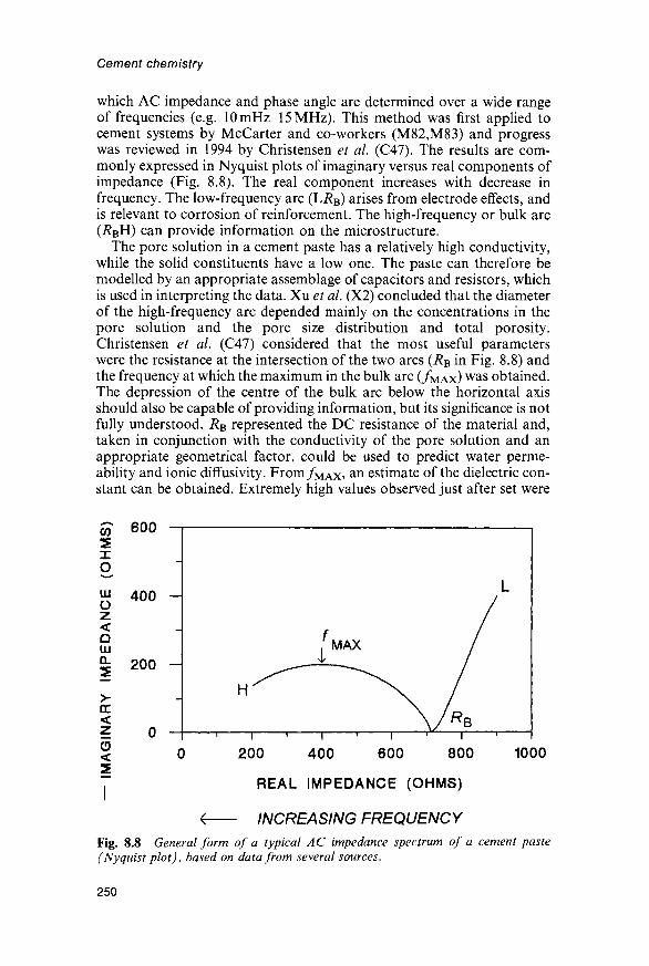
Cement chemistry
which AC impedance and phase angle are determined over a wide rangeof frequencies (e.g. 10mHz-15MHz). This method was first applied tocement systems by McCarter and co-workers (M82,M83) and progresswas reviewed in 1994 by Christensen et al. (C47). The results are com-monly expressed in Nyquist plots of imaginary versus real components ofimpedance (Fig. 8.8). The real component increases with decrease infrequency. The low-frequency arc (LRB) arises from electrode effects, andis relevant to corrosion of reinforcement. The high-frequency or bulk arc(i?BH) can provide information on the microstructure.
The pore solution in a cement paste has a relatively high conductivity,while the solid constituents have a low one. The paste can therefore bemodelled by an appropriate assemblage of capacitors and resistors, whichis used in interpreting the data. Xu et al. (X2) concluded that the diameterof the high-frequency arc depended mainly on the concentrations in thepore solution and the pore size distribution and total porosity.Christensen et al. (C47) considered that the most useful parameterswere the resistance at the intersection of the two arcs (RB in Fig. 8.8) andthe frequency at which the maximum in the bulk arc (/MAX) was obtained.The depression of the centre of the bulk arc below the horizontal axisshould also be capable of providing information, but its significance is notfully understood. RB represented the DC resistance of the material and,taken in conjunction with the conductivity of the pore solution and anappropriate geometrical factor, could be used to predict water perme-ability and ionic diffusivity. From/M A X , an estimate of the dielectric con-stant can be obtained. Extremely high values observed just after set were
< 0 200 400 600 800 1000
7 REAL IMPEDANCE (OHMS)
< INCREASING FREQUENCYFig. 8.8 General form of a typical AC impedance spectrum of a cement paste(Nyquist plot), based on data from several sources.
250

Structure and properties of Portland cement pastes
attributed to an effect known as dielectric amplification arising from theassociation in the material of capillary pores with thin layers of relativelynon-conducting solid. The pores were considered to provide many almostpurely conductive channels which stretched across the entire length ofthe system, and which were blocked by very thin barriers provided by thehydrated material. Each such barrier contributed an abnormally highcapacitance, and all were in parallel. In principle, information can beobtained on the distribution of pore sizes and the thickness of the productlayers separating the pores.
8.4.8 Other methodsThe remaining methods to be described are also ones that can be appliedto undried material. Small-angle X-ray scattering gives information onthe areas of surfaces between regions of markedly different electrondensity. For saturated, mature cement pastes of w/c 04-0-6, Winslowand Diamond (W27,W28) obtained values of 700-800 m2 per g ignitedmass, decreasing to around 200m2g~1 on D-drying. The decrease withloss of water was reversible if the specimen was not heated. Correctionfor CH and unreacted clinker phases would increase the values for thesaturated pastes to around 1000m2g~1. The authors were uncertainwhether the method would be sensitive to an interlayer of water mole-cules, but the value obtained is about what would be expected for layersof C-S-H thus separated. The decrease on drying could be attributedto the coming together of the layers, and its reversibility agrees withthe hypothesis that the loss of interlayer water on D-drying is reversible.The very high X-ray intensity obtainable from a synchrotron source hasallowed the method to be extended to pastes at early ages (W29); thesurface area scarcely changed until the the time of final set, and increasedsteadily thereafter. Information on fractal types and dimensions on scalesof 3-150 nm was also obtained (W30).
Small-angle neutron scattering may be used in a somewhat similar way.It is especially sensitive to concentrations of H atoms. A study of the3-25 nm range by this method showed a bimodal distribution of porespeaking at approximately 5nm and 10 nm, but accounting for less than2% of the total porosity (A21,P43). The pores were considered to beapproximately spherical, and on heating the material at 105°, partialcollapse of the pore structure was observed, with loss of the lOnm peak.
Proton NMR by pulsed techniques to permit the study of relaxationeffects provides information on the distribution of protons, and thus ofwater molecules, between different environments. An early study (S95)indicated that, at RH<70%, the evaporable water in hep was in anenvironment similar to that of the interlayer water in clay minerals or incertain crystalline hydrates. Subsequent work (B126,M84,M85,S96) hasgiven indications of the distributions of both chemically bound andunbound water among a number of environments and has providedinformation on changes in pore structure and specific surface area. Themethod can be applied most effectively only to materials very low in ironor other paramagnetic atoms.
251

Cement chemistry
Low-temperature calorimetry (B127,S97) has been used to study coarseporosity. The method is based on the fact that water in pores freezes at alower temperature than water in bulk. The ice forms through the advanceof a front, analogous to the intrusion of mercury or the desorption ofwater. Hysteresis effects indicated the existence of necks in the pores, andthe occurrence of up to three distinct peaks on curves of apparent heatcapacity against temperature was interpreted as indicating maxima in thepore size distribution. Coarsening of the pore structure on drying wasconfirmed.
8.5 Strength8.5.1 Empirical relations between compressive strength and porosityThe physical properties of concrete are only partly determined by thoseof the cement paste that it contains. These properties will be consideredhere only for hep and to the extent that chemical or microstructuralstudies have contributed to an understanding of them. Other aspects aretreated elsewhere (e.g. M86).
Factors determining the compressive strength of a cement paste include:(i) the characteristics of the cement, such as clinker composition andmicrostructure, gypsum content and particle size distribution; (ii) the w/cratio and the contents of air and of any admixtures present in the mix;(iii) the mixing conditions; (iv) the curing conditions, especially tempera-ture and RH; (v) the age; (vi) the manner of testing, including the watercontent of the specimen. The effects of temperature and admixtures areconsidered mainly in Chapter 11, and some additional factors relevant tomortar or concrete are considered in Section 12.1. In various ways, thefactors listed above determine the degrees of hydration of the clinkerphases and the phase composition and microstructure of the hardenedpaste, which in turn determine its physical properties, including strength.
Many empirical relations between compressive strength and one ormore of these variables have been proposed. Thus, Feret's law (1892)states that the strength is proportional to [c/(c + w + fl)f, where c, wand a are the volumes of cement, water and air respectively, and variousauthors have reported equations based on regression analyses relatingstrength to cement composition and other variables (e.g. A22,A23). Thegenerality of such equations appears to be limited, probably because ofthe difficulty of taking into account all the relevant parameters.
The porosity of the hardened paste, appropriately defined, is stronglycorrelated with strength. As seen in Section 8.3.2, it depends primarily onthe degree of hydration and the w/c ratio. In this discussion, the followingsymbols are used:
a — compressive strength<j0 = hypothetical maximum compressive strength attainablep = porosity, which has usually been taken to mean total porosity
p0 = hypothetical porosity at or above which the strength is zero
A, B, C, D and E are constants.
252

Structure and properties of Portland cement pastes
Powers (P36) found that cement pastes of various degrees of hydrationand w/c ratio conformed to the relation
a = a0XA (8.6)
where X is a quantity called the gel/space ratio, and equal to the volumeof hydration product divided by that of hydration product plus capillaryporosity, both quantities being defined as in Sections 8.2.1 and 8.3.2. Thevalue of A was about 30 if non-evaporable water was used as a measureof the degree of hydration, and typical values for a0 were 90-130 MPa.This equation breaks down for mature pastes of low w/c ratio, because itimplies that the strength does not then depend on the w/c ratio. In reality,strength increases with decreasing w/c ratio, even though some of thecement does not hydrate.
Several empirical relationships between porosity and strength, orig-inally found to hold for other materials, have been applied to cementpastes, viz.
a=ao(l-p)B (B128) (8.7)
a = a0 exp (-Q?) (R42) (8.8)
a=D\n(po/p) (S98) (8.9)
a=ao(l-Ep) (H51) (8.10)
Equation 8.7 is similar to that of Powers, but unreacted cement isconsidered equivalent to hydration product. Some of these equationsbreak down at zero or high porosities, but for a wide range ofintermediate porosities, assuming suitable values of the constants, anyof them can give a reasonable fit to a given set of data. Rossler and Odler(R40) concluded that equation 8.10 was the most satisfactory. A relationidentical to that of this equation, using capillary porosity, is implicit in afigure presented earlier by Verbeck and Helmuth (VI).
8.5.2 Relations between strength and microstructure orpore size distribution
There are several indications that the compressive strength does notdepend solely on porosity. In general, procedures that accelerate earlyreaction and thus increase early strength, such as increase in temperatureor addition of certain admixtures, tend to decrease later strength. It isunlikely that they significantly alter the porosity of the mature paste, butthey may affect the microstructure. If one extends consideration to awider range of materials than normally cured Portland cement pastes, therelation between strength and porosity is markedly dependent on thebroad characteristics of the microstructure. Jambor (J33) concluded thatboth the volume and the specific binding capacities of hydration productsmust be considered.
Feldman and Beaudoin (F40) showed that, while the strengths ofPortland cement pastes could be fitted to a curve in accordance withequation 8.8, materials of a broadly similar type but composed largely of
253

Cement chemistry
denser, crystalline particles were, for a given porosity, stronger at lowporosities and weaker at high porosities (Fig. 8.9, curves AB and CD).These materials comprised hot-pressed cement pastes (Section 11.9.1) andautoclaved cement pastes to which no silica had been added (Section 11.7).Feldman and Beaudoin considered that, while porosity was the majorfactor controlling strength, the morphology and density of the particleswere also important. At high porosities, the better bonding properties ofill-crystallized material augmented the strength, but at low porosities thegreater intrinsic strength of the dense, crystalline particles was moreimportant. In agreement with Bozhenov et al. (B129), they concluded thatthe highest strengths for a given porosity could be obtained from anappropriate blend of the two types of particles. Such a blend could berealised in autoclaved cement-silica materials (curve EF).
The size and shape distribution of the solid particles in a cement pasteis related, though in a complex way, to that of the pores, and otherworkers have attempted to relate strength to pore size distribution. Fromstudies on autoclaved materials, Mindess (M87) concluded that, for a givenporosity, the strength increased with the proportion of fine pores. Jambor(J33) similarly found relations between strength and average pore size. Theweaker materials, with relatively coarse pores, were ones containing dense,crystalline phases, and broadly resembled those represented by the high-porosity end of curve CD in Fig. 8.9. Odler and Rossler (O22) concludedfrom a study of cement pastes cured for various combinations of w/c,temperature and time that while the main factor influencing strength was
-1000
10 40 5020 30POROSITY (%)
Fig. 8.9 Relations between compressive strength (log scale) and porosity; data fromvarious sources for Portland cement pastes cured at ordinary temperatures (opencircles), hot-pressed Portland cement paste (solid circle), autoclaved pastes of Port-land cement, sometimes with added sulfur (solid squares) and autoclaved pastes ofPortland cement with 50% (open squares) or 30% (cross) of added fly ash. After F40.
254

Structure and properties of Portland cement pastes
porosity, pores with a radius below 10 nm were of negligible importance.This conclusion, which was based on results of MIP, was supported by theobservation that the specific surface area, which depends on the content ofvery small pores, had very little effect on the strength. For a given porosity,a given volume of hydration products contributed more to the strengththan the same volume of unreacted cement, but this effect was distinctly lessthan that of porosity.
These results suggest that, in attempts to relate strength to porosity, thetotal porosity should not be used, the capillary or free water porosity orthe volume of pores above a certain size being more appropriate. Parrottand Killoh (P35), in relation to their modelling of properties, similarlyconsidered the volume, size and continuity of the larger pores to be therelevant quantities.
8.5.3 Mechanisms of failureStrength cannot be explained by relating it empirically to porosity or poresize distribution; it is necessary to know what holds the material togetherand what happens when it fails. Cohesion has often been attributed to theinterlocking of fibrous or acicular particles. This could be important in themore porous parts of the material, but in the material as a whole, attractiveforces between those parts of adjacent layers of C-S-H or other phases thatare in contact are probably more important, both within particles and, in sofar as the material is particulate, between them. The attractive forces couldbe direct, or indirect, through interposed water molecules. Even for D-driedmaterial, analogies with crystalline tobermorite and jennite indicate thatmuch interlayer water is still present (Section 5.4).
Various authors have discussed the application of fracture mechanicsto cement paste (A24,B130,E4,J33,P44). As in other brittle materials,failure occurs through the initiation and spread of cracks, which originatein places where the local stress is high. Hardened cement pastes are aboutten times as strong in uniaxial compression as in tension. It is probablethat the ultimate mechanisms of failure are essentially similar, but thatthe cracks propagate more readily under tension. The relations betweenmicrostructure and strength must thus be sought in the features that giverise to high local stresses and in those that favour or, conversely, thatarrest the spread of cracks. This is consistent with the conclusion thatporosity is a major factor but not the only one; Beaudoin and Feldman(B130) discussed some others, in addition to those noted above. Thestrength, however measured, is less for a saturated paste than for a dryone. In principle, this is readily explained, as the entry of water moleculesbetween particles could weaken the attractive forces between them andthereby favour the initiation or spread of cracks. A disjoining pressure iscreated (Section 8.2.4).
8.6 Deformation8.6.1 Modulus of elasticityCurves of uniaxial compressive stress against strain for hep are non-linearand vary somewhat with the strain rate. Caution is therefore needed in
255

Cement chemistry
comparing values of Young's modulus obtained in different investiga-tions, results obtained at very low stresses by the dynamic method inwhich a resonance frequency of vibration is determined being higher thanones given by static or slow loading methods and averaged over greaterranges of stress. Using the dynamic method, Helmuth and Turk (H52)obtained values of 20 000-30 000 MPa for saturated, mature pastes.Trends with w/c and degree of hydration, and relations with porosity,were similar to those for compressive strength. For saturated pastes,Helmuth and Turk found
E=E0(l-pc? (8.11)
where E is Young's modulus, Eo is its value extrapolated to zero porosity,and pc is the capillary porosity. For two cements, Helmuth and Turkfound Eo to be approximately 30 000 MPa. The same equation heldequally well for total porosity if values around 75 000 MPa were used forEo. They also found (H53) that, for a series of pastes 6-7 months old, theirreversible shrinkage at 47% RH was linearly related to the totalporosity, whereas the reversible shrinkage was practically independent ofthe porosity.
Sereda et al. (S93) found that, as with compressive strength, the valuesobtained depend on the RH at which the sample is conditioned, but thatthe effect is in the opposite direction, saturated pastes having highermoduli than dried pastes. This was attributed to stiffening of the structurethrough entry of water molecules into interlayer sites, possibly aug-mented by stronger bonding between adjacent layers (F36,S93,S99).Hysteresis occurred, and was explained by assuming that entry and exitof water begins at the edges of the layers, and that the modulus dependsprimarily on whether the central parts of the layers are filled. Compactsmade by compressing bottle hydrated cement at 100-750 MPa gaveresults similar to those for pastes.
8.6.2 Creep and shrinkageCement pastes expand slightly during wet curing; a small shrinkage, calledautogenous shrinkage, occurs during sealed curing. A saturated pasteshrinks on being dried. This effect, if it occurs in the absence of loading, iscalled drying shrinkage. Basic creep is slow deformation that occurs undera constant external load in the absence of drying. It is superimposed on theelastic strain that occurs when the load is applied. If drying and loadingoccur simultaneously, the deformation is greater than the sum of the twoeffects occurring separately. The excess deformation is called drying creep.Both shrinkage and creep have reversible and irreversible components.Both have important implications for the design and durability ofconcrete structures.
The changes in length, or more properly in volume, that occur throughshrinkage broadly parallel ones in water content (V7). Shrinkage iscomplicated by the effects of moisture gradients in the specimen, and to
256

Structure and properties of Portland cement pastes
minimize these and the resulting mechanical constraints it is necessary tostudy thin slices of material. Wittmann (W26) obtained data for specimensof varying thickness and extrapolated to zero thickness. Creep decreaseswith age before loading and with decreasing w/c ratio (VI). If the materialis heated at 110°C before loading and kept dry during test, creep almostdisappears. It reappears on re-exposure to water. In contrast, increase intemperature from 10°C to 60°C during loading increases creep. Heatingbefore loading causes the irrecoverable component of creep to decreaseeven if the specimen is kept saturated (P45,P46). Standing at ordinarytemperature, drying at 110°C and heating under saturated conditions areall forms of ageing, which produce a more stable structure. Irreversiblecreep may also be a form of ageing in which a similar effect is produced bystress (F41) and which occurs less readily if a more stable condition hasalready been reached through some other cause.
The interaction between shrinkage and creep implies that any fullexplanation requires that they be considered together. The dependence ofboth effects on the amount of water in the material also suggests arelationship, and, more precisely, that the properties are ones of the gel,and thus predominantly of the C-S-H. Analogy with the behaviour ofmore highly ordered forms of C-S-H suggests that changes in interlayerwater content and thus also in layer thickness play a part in shrinkage,but changes in pore structure could equally well be important. Thebehaviour in a mortar or concrete is unlikely to depend solely on effectsthat apply to a bulk paste; the interfacial transition zone adjacent to theaggregate surfaces is likely to have a major effect.
Many theories have been proposed in relation to both shrinkage andcreep, but none has received universal acceptance (H54,M86,X3). Allimply changes either in the characteristics or relative positions of the gelparticles or in the pore structure, or both, but inadequate knowledge ofthe relevant features of the microstructure has in most cases precludeddescriptions in terms of any but the most generalized microstructuralmodels. For both shrinkage and creep, more than one mechanismprobably operates; the dominant mechanism for shrinkage is probablynot the same for different ranges of RH. Several of the theories have beenformulated into mathematical expressions that agree with the data over alimited range, but, as Xi and Jennings have pointed out (X3), this has notproved sufficient to establish the correctness of the mechanism. Anycomprehensive theory must not only be able to explain the observationsat the macroscopic level, but also be capable of being tested at themicrostructural level. For this to be possible, more detailed knowledge ofthe pore structure and of the interactions between the various phases isneeded, both for bulk paste and for the interfacial transition zone adjacentto aggregate surfaces. Direct observations of shrinkage in the environ-mental SEM, in which the specimen is maintained in a humid atmosphere,have been reported (X3), and constitute a promising approach. A pressingneed is for data that could provide a basis for fundamental, microstruc-tural modelling of the type that has proved fruitful in the understandingof permeability and diffusion.
257

Cement chemistry
8.7 Permeability and diffusion8.7.1 Permeability to waterThe permeability of concrete and the rates at which ions and gases diffusein it are of major importance for durability. Only the behaviour ofcement paste will be considered. Brown et al. (B124) reviewed relationsbetween permeability and porosity. Under certain experimental condi-tions permeability to water obeys D'Arcy's law:
dq/dt = K{ A- Ah/1 (8.12)
where dq/dt is the flow in m3 s"1, K\ is the permeability in m s"1, A is thecross-sectional area in m2, Ah is the head of water in metres, and / is thethickness of the specimen in metres. K\ depends on the viscosity of theliquid, the temperature and the properties of the material. Importantconditions are that the sample is completely saturated, steady flow ismaintained, and osmotic effects, such as might be caused by concentra-tion gradients in dissolved ions, are absent. Feldman (F42) gave a review,including references to experimental techniques.
Powers and co-workers (P20,P36,P47) determined values of Kx of hepfor various combinations of w/c and age. They assumed that the capillarypores in the paste were initially continuous, but that at a certain stage inhydration they became segmented into isolated cavities, so that the watercould only travel through the gel pores, causing the permeability todecrease to a very low value. They concluded that the age at which thecapillaries became discontinuous increased with w/c. For a typical cement,it was about 3 days at w/c = 0-4, 1 year at w/c 0-7 and unattainable atw/c > 0-7. Reinterpreting some of these data, Verbeck and Helmuth (V7)concluded that the permeability was directly related to the capillaryporosity.
Subsequent studies have shown that Kx depends on the volume andconnectivity of the larger pores. Mehta and Manmohan (M88) andNyame and Illston (N18) found linear relations between log Kx and esti-mates of the maximum continuous pore radius, obtained from MIP, andother quantities derived from the pore size distribution and degree ofreaction. A high proportion of the flow appears to be through poreswider than about lOOnm. Typical values of \ogKx for mature pastescured at ordinary temperatures range from around -13-4 at w/c 0-3 toaround -11-8 at w/c 0-7 (G78,H55,M88,M89,N18). Kx increases withtemperature (G78,M89).
Hooton (H56) noted some pitfalls in the experimental determination ofpermeabilities and in the practical utilization of the results. In anexperimental determination, accurate results will not be obtained unlessthe sample has been vacuum saturated; and, even if it is, equilibrium flowin accordance with D'Arcy's law may not occur because water is beingused up to continue hydration. In practice, a concrete sample is probablynot often saturated throughout; if it is not, capillary forces, as well as thepressure difference, affect the rate of flow. Applications of results obtainedwith pastes to concrete are further complicated by the presence in thelatter of cracks, poorly compacted areas and other inhomogeneities.
258

Structure and properties of Portland cement pastes
8.7.2 Diffusion of ions and gasesUshiyama and Goto (U16) studied the diffusion of ions in a Portlandcement paste of w/c ratio 04 cured at 20°C for 28 days. Fick's second lawwas shown to be followed when a steady state had been reached. For Li+,Na+and K+, diffusion coefficients of 14-3-3 x 10~l2m2s~1 were obtained.That of Cl" was somewhat greater, especially if the balancing cation wasCa2+ or Mg2+. It was shown that CH and MH crystallized at the surfaceof the specimen, suggesting that CH within the specimen had dissolved.
Other studies on Na+ and Cl" (C48,G79,H57,P48) have given resultsin substantial agreement with those above. At ordinary temperatures,the diffusion coefficients obtained have been 10~n to 10~13m2s~1 forNa+ and 10~u to 10~12m2s~1 for Cl~. The activation energies arereported to be 84kJmol~1 for Na+ and 50kJmol~1 for Cl~ for w/c ratiosof 0-35-045 (G79), or 42-45 klmol"1 for Cl" at w/c ratios of 04-0-5and 32kJmol~1 for w/c = 0-6 (P48). These activation energies are muchhigher than those found for diffusion of the same ions in a dilute solution,which are typically below 20kJmol"1. One study (G79) showed littleapparent variation in diffusion coefficients with w/c ratio or age, butanother (H57) showed increases with w/c ratio and decreases as hydra-tion proceeded.
Studies on the permeability and diffusivity of concrete to gases,reviewed by Feldman (F42), have provided only slight informationregarding the mechanism of transport through the cement paste or therelations to its pore structure. It cannot be taken for granted that theirrelation to pore structure is the same as that for water permeability.
Garboczi and Bentz (G80) calculated ionic diffusivities in a saturatedpaste from their model of paste structure. For this purpose, the system wastreated through the analogy of a random network of electrical conduc-tors. Based on experimental data, conductances were assigned to contactsbetween adjacent pixels within and between capillary pores, C-S-H andthe electrodes. For the C-S-H, data for diffusion of Cl~ were used. Theresults were in reasonable agreement with experimental data, which wereavailable for the higher degrees of hydration. At porosities above 18%,the dominant pathways were through capillary pores, with somecontribution from gel pores in the C-S-H; at lower porosities, theywere through isolated isolated regions of capillary pore space linked bygel pores. This conclusion is similar to that relating to water permeability,discussed above. A single curve relating the relative diffusivity (diffusivityrelative to that of the ions in free water) to the capillary porosity wasfound to apply to all the simulation data points for plain C3S pastes atcapillary porosities up to 60%.
259

9 Composite cements
9.1 IntroductionA composite cement is a hydraulic cement composed of Portland cementand one or more inorganic materials that take part in the hydrationreactions and thereby make a substantial contribution to the hydrationproduct. This definition excludes admixtures, such as CaCl2, that influ-ence the hydration process but do not themselves contribute substantiallyto the product. The inorganic materials will be called mineral additions;other terms, such as supplementary cementing materials (SCMs), are alsoused. The most important are flyash (pulverized fuel ash), groundgranulated blastfurnace slag (ggbs), natural pozzolanas and silica fume(microsilica). The mineral addition may be ground together with thecement clinker and gypsum, or mixed with Portland cement when thelatter is used. In British usage, these procedures are called intergrindingand blending respectively. In US usage, the term 'blended cements' iswidely used as a synonym for composite cements of either type.
Composite cements are used for various reasons. The necessity forutilizing waste materials and decreasing overall energy consumption isbecoming increasingly obvious. Flyash and slag are waste materialsproduced in large quantities, and concretes made with them, or withnatural pozzolanas, can have properties similar to those of ones madewith pure Portland cements at lower cost per unit volume. Concretesmade using composite cements can have properties that are desirable forparticular purposes, such as slower and decreased total heat evolution inmassive structures, improved durability or, especially with silica fume,strengths above the normal range.
Mineral additions may be broadly categorized as pozzolanic materialsor latent hydraulic cements. Neither type reacts significantly with waterat ordinary temperatures in the absence of other substances. Pozzolanicmaterials are high in SiO2 and often also in Al2O3; they are sufficientlyreactive that mixtures of them with water and CaO produce C-S-H atordinary temperatures and thereby act as hydraulic cements. If theycontain A12O3, calcium aluminate hydrates or aluminate silicate hydratesare also formed. Because they are low in CaO, this component must besupplied in stoichiometric quantity. In a composite cement, it is providedby the Portland cement through decreased formation of CH and
261

Cement chemistry
decreased Ca/Si ratio of the C-S-H. Flyash low in CaO, naturalpozzolanas and silica fume are examples of pozzolanic materials.
Latent hydraulic cements have compositions broadly intermediatebetween those of pozzolanic materials and Portland cement. They act ashydraulic cements if mixed with water and a minimal amount of someother substance that serves as a catalyst or activator. Ggbs is a latenthydraulic cement. When mixed with Portland cement, it is activated bythe CH and alkali which the latter produces. As will be seen, thehydration products of the Portland cement clinker are also modified. Theproportion of a latent hydraulic cement in a composite cement can behigher than that of a pozzolanic material. Some materials, such as finelyground CaCO3, though used in relatively small proportions and havingneither pozzolanic nor latent hydraulic properties, are convenientlyconsidered along with mineral additions.
In this chapter and elsewhere, w/s denotes the ratio wj(c+p) and'percentage replacement' the quantity 100/?/(c-f/?), where w, c and/7 arethe masses of water, Portland cement and mineral addition respectively.
9.2 Blastfurnace slag9.2.1 Formation, treatment and use in composite cementsBlastfurnace slag is formed as a liquid at 1350-1550°C in the manu-facture of iron; limestone reacts with materials rich in SiO2 and A12O3
associated with the ore or present in ash from the coke. If allowed to coolslowly, it crystallizes to give a material having virtually no cementingproperties. If cooled sufficiently rapidly to below 800°C, it forms a glasswhich is a latent hydraulic cement. Cooling is most often effected byspraying droplets of the molten slag with high-pressure jets of water. Thisgives a wet, sandy material which when dried and ground is called groundgranulated blastfurnace slag and often contains over 95% of glass.
In an alternative treatment, called pelletization, the molten slag ispartially cooled with water and flung into the air by a rotating drum. Theresulting pellets vary in size from a few mm to around 15 mm. Theproportion of glass decreases with increasing pellet size. Pelletization hasadvantages to the steel manufacturer of lower capital cost, decreasedemission of sulfurous gases, and formation of a drier product, which canalso be sold as a lightweight aggregate, but the glass content of the sizefraction used to make composite cements can be as low as 50%.
The composition of the slag must be controlled within relativelynarrow limits to ensure satisfactory and economic operation of the blast-furnace, and depends on that of the ore. It therefore varies considerablybetween plants, but that of a given plant is unlikely to vary much unlessthe source of the ore is changed. Table 9.1 gives ranges and means forslags typical of those produced in Western Europe. For a wider rangeof steel-producing countries, the contents of major components are:MgO, 0-21%; A12O3, 5-33%; SiO2, 27-42% and CaO, 30-50% (S100).The densities of granulated or pelletized blastfurnace slags are typically2880-2960 kg m~3.
262

Composite cements
Table 9.1 Chemical compositions of some blastfurnace slags* (D49)
Na2OMgOA17O,SiO2fP?O,SO3K2OCaO
Mean
0-395-99
13-2933480130040-70
42-24
Minimum
0-253-63
10-2631-960000000-44
37-92
Maximum
0-508-66
160137-290-340190-98
44-38
TiO2
MnOFeOs2-F"ci-Ign. lossTotal}
Mean
0-550-641-240-9401600190-42
99-68
Minimum
0-490-340-290-680060-0030-00
Maximum
0-651-319-321-250-310-050104
* Means, minima and maxima for 27 slags representative of French and Luxembourgproduction in 1980.f Total SiO2; insoluble residue, mean, 0-41%, minimum, 000%, maximum, 1-32%.\ Corrected for O2~ equivalent to S2~, F~ and Cl~.
In composite cements, the granulated or pelletized slag is blended orinterground with Portland cement or clinker. Ternary mixes containingalso, for example, natural pozzolanas are used in some countries. Slagsvary considerably in grindability, but are usually harder to grind thanclinker. Intergrinding may therefore produce a cement in which the slag istoo coarsely, and the clinker too finely, ground. For this and otherreasons, there can be a case for separate grinding, at least with somecombinations of clinker and slag (S101). The relative proportions ofclinker and slag vary widely; the content of slag can be over 80%, but upto 45% is more usual. Specifications and terminology based on them varyin different countries. In current (1996) British standards, cements withup to 35% of slag are called Portland slag cements, and ones with36-85% of slag are called blastfurnace cements.
In this chapter, unless otherwise stated, the term 'slag' is used to meangranulated or pelletized blastfurnace slag, and 'slag cement' to meancomposite cements consisting essentially of these materials with Portlandcement or clinker. In these cements, the slag reacts considerably moreslowly than the alite, and strength development is therefore slower to anextent that increases with the proportion of slag. For equal 28-daystrengths, replacement of a Portland cement by one containing 65% ofslag can lower the compressive strength by almost a half at 2 days, butincrease it by about 12% at 91 days (S100). Workability is similar to thatobtained with Portland cements. The rate of heat evolution at early agesand the total heat evolution are both reduced. Fuller comparisons wouldhave to take account of the proportion of slag, the particle sizedistributions of clinker and slag, and the fact that slags vary in reactivity.
9.2.2 Factors affecting suitability for use in a composite cementThe suitability of a slag for use in a composite cement depends primarilyon its reactivity, though grindability and contents of water and ofundesirable components, especially chloride, must also be considered.
263

Cement chemistry
Reactivity most obviously depends on bulk composition, glass contentand fineness of grinding, though these are probably not the only factorsand the relations with composition and glass content are complex.
Several investigators have found that the presence of a small proportionof crystalline material finely dispersed in the glass improves grindability orreactivity or both (SI00). Demoulian et al. (D49) found that the higheststrengths at 2-28 days were given by slags containing about 5% of crystal-line phases and that increase in the content of the latter up to 35%produced only small decreases in strength. They attributed the beneficialeffect of small contents of crystalline phases to mechanical stress in theglass and provision of nucleation sites for hydration products, and thesmallness of the decrease at high contents to a consequent change in theglass composition, which through the separation of merwinite wasenriched in A12O3.
Smolczyk (SI00) reviewed relations between composition and hydraulicproperties. Many attempts have been made to assess slags on the basis ofmoduli based on bulk composition, of which (CaO + MgO + Al2O3)/SiO2is one of the simplest and most widely used. Minimum values for this ratio(e.g. 1-0) have sometimes been incorporated into standard specifications.This and similar moduli express the fact that hydraulic activity is broadlyfavoured by more basic composition, but the effect of A12O3 content iscomplex and none of the proposed moduli has proved valid for thedetailed comparison of slags other than ones of relatively similar composi-tions produced within a given plant. A regression analysis of compressivestrengths on compositions for composite cements made using a widerange of west European slags (SI02) showed that increase in A12O3
content above 13% tended to increase early strengths but to decrease latestrengths. MgO in amounts up to 11% was quantitatively equivalent toCaO. Minor components were found to have important effects: that ofMnO was always negative, but those of P2O5 and of alkalis were morecomplex.
9.2.3 X-ray diffraction and microstructure of slagsRegourd (R43) reviewed structural and other aspects of slags. XRDpatterns show an assymetric, diffuse band from the glass peaking at about31° 20 (CuKa; d=029nm) and extending from about 20° to about 37°and a weaker band at about 48° 20 (019nm). Crystalline phases, ifpresent in sufficient quantity, give superimposed, sharper peaks; meliliteand merwinite are the most usual. Neither periclase nor lime is foundand, since it is present either in the glass or in these inert, crystallinephases, MgO is not a potential cause of expansion, as it may be in aclinker (SI03).
Glass contents have been determined by light microscopy and bydifference from QXDA determinations of crystalline phases (R43,R44,S104,U17). Investigators have differed as to how well the results of thetwo methods agree. Both will fail if the individual crystalline regions arebelow a certain size, which is much smaller for QXDA than for lightmicroscopy, but light microscopy complements QXDA by providing
264
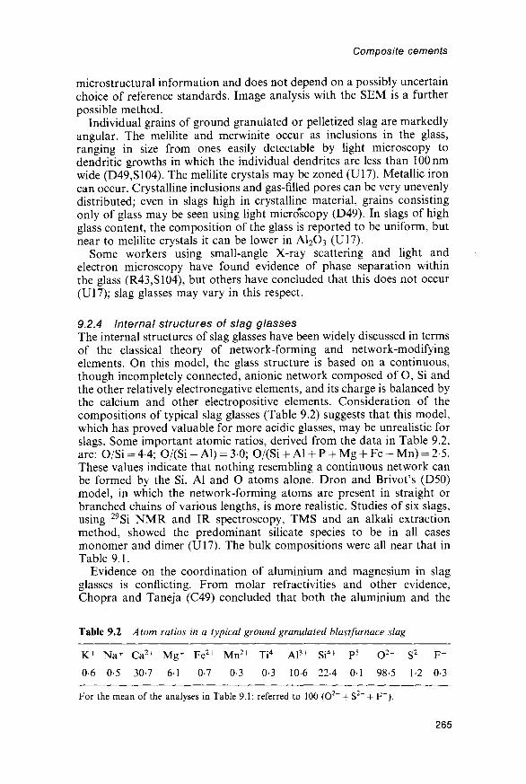
Composite cements
microstructural information and does not depend on a possibly uncertainchoice of reference standards. Image analysis with the SEM is a furtherpossible method.
Individual grains of ground granulated or pelletized slag are markedlyangular. The melilite and merwinite occur as inclusions in the glass,ranging in size from ones easily detectable by light microscopy todendritic growths in which the individual dendrites are less than lOOnmwide (D49,S104). The melilite crystals may be zoned (U17). Metallic ironcan occur. Crystalline inclusions and gas-filled pores can be very unevenlydistributed; even in slags high in crystalline material, grains consistingonly of glass may be seen using light microscopy (D49). In slags of highglass content, the composition of the glass is reported to be uniform, butnear to melilite crystals it can be lower in A12O3 (U17).
Some workers using small-angle X-ray scattering and light andelectron microscopy have found evidence of phase separation withinthe glass (R43,S104), but others have concluded that this does not occur(U17); slag glasses may vary in this respect.
9.2.4 Internal structures of slag glassesThe internal structures of slag glasses have been widely discussed in termsof the classical theory of network-forming and network-modifyingelements. On this model, the glass structure is based on a continuous,though incompletely connected, anionic network composed of O, Si andthe other relatively electronegative elements, and its charge is balanced bythe calcium and other electropositive elements. Consideration of thecompositions of typical slag glasses (Table 9.2) suggests that this model,which has proved valuable for more acidic glasses, may be unrealistic forslags. Some important atomic ratios, derived from the data in Table 9.2,are: O/Si - 4-4; O/(Si + Al) = 3-0; O/(Si + Al + P + Mg + Fe + Mn) - 2-5.These values indicate that nothing resembling a continuous network canbe formed by the Si, Al and O atoms alone. Dron and Brivot's (D50)model, in which the network-forming atoms are present in straight orbranched chains of various lengths, is more realistic. Studies of six slags,using 29Si NMR and IR spectroscopy, TMS and an alkali extractionmethod, showed the predominant silicate species to be in all casesmonomer and dimer (U17). The bulk compositions were all near that inTable 9.1.
Evidence on the coordination of aluminium and magnesium in slagglasses is conflicting. From molar refractivities and other evidence,Chopra and Taneja (C49) concluded that both the aluminium and the
Table 9.2 Atom ratios in a typical ground granulated blastfurnace slag
K+ Na+ Ca2+ Mg+ Fe2+ Mn2+ Ti4+ Al3+ Si4+ P5+ O2" S2~ F "
0-6 0-5 30-7 61 0-7 0-3 0-3 10-6 22-4 0-1 98-5 1-2 0-3
For the mean of the analyses in Table 9.1; referred to 100 (O2~ + S2~ + F~).
265

Cement chemistry
magnesium are tetrahedrally coordinated, as in melilites. X-ray spectro-scopic results have been held to favour tetrahedral coordination of thealuminium (G81) or a mixture of tetrahedral and octahedral coordina-tion (Y7). From electron paramagnetic resonance, Royak and Chkolnik(R45) concluded that magnesium, aluminium and titanium could each bein either tetrahedral or octahedral coordination and that increasedproportions in octahedral coordination enhanced hydraulic activity.The 27A1 NMR spectrum of a synthetic glass similar in composition totypical slag glasses showed the Al to be in distorted tetrahedral coordi-nation (R46).
Structural defects affect reactivity; four samples of the same slag liquid,cooled at different rates, differed in reactivity, though all were shown byXRD to be completely glassy (F43). Photoelectric emission data showedthat they contained different numbers of defects.
Granulated or pelletized slags are materials formed under markedlynon-equilibrium conditions, and it is not surprising that their hydraulicactivities are not determined solely by bulk composition and glasscontent. Reactivity may be presumed to depend on glass compositionrather than on bulk composition. For a given combination of glasscontent and bulk composition, further effects varying reactivity couldthus include the following:
(1) crystallite size and morphology, through their effects on stress inthe glass or nucleation sites for hydrated phases
(2) the bulk composition of the crystalline material, through its effecton that of the glass, and the profile of compositional variationin the glass near the crystallite surfaces, which could produceregions of either enhanced or decreased reactivity
(3) the degree of phase separation within the glass(4) the coordination numbers of the aluminium and magnesium,
and the distributions of atoms and bonding patterns within theglass; e.g. variation in the number of Si-O-Al linkages com-pared with those of Si-O-Si and Al-O-Al
(5) the numbers and types of electronic or structural defects.
9.2.5 Hydration chemistry of slag cementsDaimon (D51), Regourd (R47) and Uchikawa (U18) have reviewed slagcement hydration. Many XRD studies have shown that the principalhydration products are essentially similar to those given by pure Portlandcements, but the quantities of CH found by this or other methods are invarying degrees lower than those which would be given by the Portlandcement constituent if the slag took no part in the reaction (C50,K46,R47,S105). With percentage replacements above about 60%, the CHcontent may pass through a maximum and then decrease. The magnesiumin the slag enters a hydrotalcite-type phase (F44,G82,H58,K47,R48).
The microstructures of slag cement pastes are also essentially similar tothose of pure Portland cement pastes, apart from the lower CH contents
266

Composite cements
(H58,R43,U13,U18,U19). As with the clinker phases, layers of innerproduct form at the boundaries of the slag grains and gradually extendinwards. A light-microscopic study indicated that these were only 0-5 fimwide after 90 days (K46). Backscattered electron images with another slag(H58) showed them to be barely detectable at 28 days, but up to 10 fimwide at 6 months and up to 15 /im wide at 14 months. In the older pastes,fully reacted relicts of slag particles were abundant. A TEM study (R48)showed that, with increasing proportion of slag in the blend, themicrostructure of the outer product (dried by the high vacuum of theinstrument) becomes progressively less fibrillar and more foil-like incharacter. It was suggested that this could decrease the connectivity of thepore system and thereby account for the low permeabilities of slag-cement pastes. This matter is discussed further in Section 9.7.
Luke and Glasser (L30,L48) made a comparative study of methods fordetermining the content of unreacted slag. The most satisfactory was amodification of that of Demoulian et al. (D52), in which constituentsother than unreacted slag were dissolved using an alkaline solution ofEDTA in aqueous triethanolamine. Other extraction methods gaveunacceptably high residues with pastes of Portland cements. This mayexplain the very wide variation between results given in the literature.Lumley et al. (L49), using a further modification of the method ofDemoulian et aL, found that at w/s ratios of 0-4-0-6 and 20°C, 30-55%of the slag reacted in 28 days and 45-75% in 1-2 years. The degree ofreaction varied with the slag and decreased with the content of slag in theblend and with decrease in w/s.
Vernet (V8) showed that the S2~ ion in granulated or pelletized slags isalmost entirely contained in the glass and that it is released at the rate atwhich the latter reacts. He showed that it probably entered an AFmphase. Sulflde-containing phases of this type have been synthesized(D27,V8); one also containing iron was intensely green in colour and mayaccount for the characteristic colour of slag cement pastes (V8). AlthoughS2~ in AFm phases is very easily oxidized (V8), significant aerial oxida-tion does not seem to occur in the bulk of a slag cement paste. Observ-ations on a sulfide-containing Portland cement (B131) suggest, however,that in slag cements some oxidation of the S2~ by the Fe3+ present in thePortland cement component may occur. Small amounts of thiosulfatehave been detected in the pore solutions of slag cements (G83,L37).
9.2.6 X-ray microanalysisThe mean Ca/Si ratio of the C-S-H is lower than that found in pastes ofplain Portland cements (H4,H58,R36,R48,U19). Richardson and Groves(R48) found from TEM analyses that it decreased with the proportion ofslag in the blend, from around 1-8 for plain Portland cement pastes to1-1-1-2 in the extreme case of a paste of an alkali-activated slag con-taining no Portland cement. These last values were near that of theunreacted slag. For a blend with 50% slag, values in the region of 1-55were obtained. There was no significant difference in Ca/Si ratio betweenthe C-S-H present in the outer product or as inner product of the slag or
267

Cement chemistry
clinker. In contrast, another investigation (H58) showed the inner productof the clinker to have a higher Ca/Si ratio than that of the slag.
Richardson and Groves (R48) found that the mean Al/Ca ratio of theC-S-H increased with the Si/Ca ratio, in accordance with equation 7.3.The mean Al/Ca ratio is thus approximately 0-10 for a blend with 50%slag and 019 for a paste of alkali-activated slag. The significance of thelatter result is discussed in Section 9.2.9.
Harrisson et ah (H4,H58) represented the results of X-ray micro-analyses of individual spot analyses in all parts of the microstructureother than unreacted clinker grains on plots of Al/Ca ratio against Si/Caratio and of Mg/Ca ratio against Al/Ca ratio (Figs. 9.1 and 9.2). If theanalyses of the inner product of the slag are excluded, the plot of Al/Caagainst Si/Ca is broadly similar to plots obtained for pure Portlandcement pastes, and may be interpreted in the same way (Section 7.3.5)as indicating the presence of C-S-H, an AFm phase and small pro-portions of CH. Taken together, the results in the two figures show thatthe inner product of the slag has an approximately constant Si/Ca ratioof 0-62, and ratios of Mg/Ca and of Al/Ca that vary from point to pointon a micrometre scale but are related to each other by the equationshown in Fig. 9.2. This was interpreted (H58) as indicating mixtures invarying proportions of C-S-H having Si/Ca 0-62, Al/Ca 009 with a
0 4 -
0-2 -
< AFm
a x.
-
-
Ca(OH)2PU- =i
D
a
%. a
°
C-S-H*Ca
. '
Si/Ca =
;
Slag Rimsand •
Reliefs ^ »
•
•
>w. ° °
: 0 62 -
1 . •
c ,• •
m
-
-
0-2S i / C a
0-4 0 6
Fig. 9.1 Si/Ca and Al/Ca atom ratios from individual X-ray microanalyses ofa slag cement paste (40% slag; w/s = 0-5) hydrated for various times at 25°C.Mg/Si < 0-15: 0 , 28 days; • , 6 months; 0 , 1 4 months. Mg/Si > 0-15: 4 , 28 days,• , 6 months; # , 14 months. From H58.
268

Composite cements
A l / C a ' = 0 0 9 * ' o 3 8 ( M g / C a )
0 0-2 0UA l / C a
Fig. 9.2 Al/Ca and Mg/Ca atom ratios from individual X-ray microanalyses ofthe same slag cement paste as in Fig. 9.1. Si/Ca<0-5: O, 28 days; D, 6 months;O, 14 months. Si/Ca>0-5: • , 28 days; • . 6 months; %, 14 months. From H58.
hydrotalcite-type phase having Al/Mg 0.38. Similar results have beenobtained by subsequent investigators, though values varying between0-23 and 0-52 have been reported for the Al/Mg ratio of the hydrotalcite-type phase (B132,G82,R48). In some slag cement pastes, the constituentphases of the slag inner product appear to be randomly though notuniformly mixed at the micrometre level (e.g. H58), but in other casesdistinct zones enriched in C-S-H and in the hydrotalcite-type phase havebeen observed (B132,F44,T50). T
269

Cement chemistry
The AFm phase formed in pastes of slag cements approximates tomonosulfate at early ages but appears to take up increasing proportionsof S2~ as hydration proceeds (G82). With slags high in A12O3 or blendshigh in slag, there are indications that a phase higher in A12O3, possiblystratlingite, is also formed (G82). Some of the AFm phase is present inthe slag inner product (Figs 9.1 and 9.2).
9.2.7 Stoichiometry of slag cement hydrationAn approximate estimate of the stoichiometry of slag hydration can beobtained as follows (Table 9.3).
(1) Assume that the MgO from the slag enters a hydrotalcite-typephase, for which one must assume an Mg/Al ratio (e.g. 2-5).
(2) Assume that the SiO2 from the slag enters C-S-H, for whichone must assume a Ca/Si ratio, and also, using equation 7.3, anAl/Ca ratio (e.g. Ca/Si 1-55, Al/Ca 0-09).
(3) Assume that the remaining A12O3 is contained in an AFm phase;this probably also contains the S2~ released from the slag.
(4) The amount of CaO released from the slag will be insufficient toaccount for that in the C-S-H and AFm phase. The deficiency ismade up by decreases in the content of CH and the Ca/Si ratio ofthe C-S-H formed from the Portland cement or clinker.
Comparison of the average proportions, compositions and densities ofthe phases present in the inner product of the slag with correspondingdata for the unreacted slag suggests that little net movement of eitherMg2+ or O2~ in or out of the latter occurs when it reacts, but that sub-stantial fractions of the Al3+, Si4+ and Ca2+ are expelled and anequivalent amount of H + taken up (H58). The ions thus releasedcontribute to the outer product; as explained above, more Ca2+ isprovided by the Portland cement or clinker to alter the atom ratios tothose in a mixture of C-S-H and AFm phase.
For any specified drying condition, the observed water contents ofslag blends are lower than those of comparable plain Portland cementpastes (C50,H58,H59). In some typical cases of mature pastes, the bound
Table 9.3 Calculated mass balance for hydration of a granulated blastfurnace slagin a blend with Portland cement
SiO2 A12O3 CaO MgO S2~
Total supplied by slag glassHydrotalcite-type phaseC-S-HAFmSupplied by Portland cement
33-0
330
11433
•8•8•91
410
47-76-8
13-5
99
•5
•511
10
All values are in g per lOOg of reacted slag glass. The basis of the calculation and com-positions assumed for the hydration products are explained in the text.
270

Composite cements
water contents decreased from around 27% for plain Portland cement to22-24% for blends containing 70% of slag (H59). Mass-balance calcula-tions lead to a similar conclusion (H58), which appears to hold forcomposite cements in general.
9.2.8 Activation of slag glassesIf ground granulated or pelletized blastfurnace slag is placed in wateralone, it dissolves to a small extent but a protective film deficient in Ca2+
is quickly formed, and inhibits further reaction (K21,R49). Reactioncontinues if the pH is kept sufficiently high. The pore solution of a Port-land cement, which is essentially one of alkali hydroxides, is a suitablemedium. The supply of K+ and Na+ ions is limited, but these ions areonly partially taken up by the hydration products, and the presence ofsolid CH ensures that the supply of OH~ is maintained. The slag cansimilarly be rendered active by OH~ ions supplied in other ways, such assodium hydroxide or silicate (Section 9.2.9). Although several hypotheseshave been proposed, the mechanism of the attack on the slag glass is notestablished. If it is similar to that suggested for the clinker phases (Section4.6.1), one would expect reactivity to increase with the fraction of theoxygen atoms bonded only to calcium and a single silicon, or, especially,to calcium and a single aluminium atom.
Calcium sulfate accelerates the reaction of slag glasses, probablybecause precipitation of ettringite provides a sink for the Ca2+ andAl(OH)^ ions released from the slag. It is often described as an activator,but is not very effective unless a little alkali is also present (R47) and isperhaps more properly described as a powerful reactant. The calciumsulfate present in a slag cement thus contributes to increasing the activityof the slag. The reaction between slag and CaSO4 is utilized to a muchgreater extent in supersulfated cements.
9.2.9 Alkali-activated slag cementsThese were pioneered by Glukhovsky et al. (G84) and their propertieswere reviewed by Wang et al. (W31). Typically, they consist of ggbs with3-5-5-5% of Na2O, added usually as NaOH or sodium silicate. Desirableproperties include rapid hardening, high strength development, low heatof hydration, low permeability and good resistance to chemical attack,but problems exist with quick setting, possible likelihood of alkali silicareaction, efflorescence and high drying shrinkage.
As noted in Section 9.2.6, the main hydration product is C-S-Htypically having Ca/Si 1-1-1-2 and Al/Ca around 019. Studies of pastesof alkali activated slag or synthetic slag glass by NMR and ELNES(electron energy loss near-edge structure) showed that the aluminium inthe C-S-H substituted for silicon exclusively in bridging sites of dreier-ketten having a mean chain length of 4-83 tetrahedra (B133,R46,R50).Substitution of silicon by aluminium in these sites was almost complete.
A hydrotalcite-type phase is also formed; AFm phase appears also tobe formed with some, but not all, slags (R48,W32). If NaOH is used as
271

Cement chemistry
activator, the C-S-H is relatively highly ordered C-S-H(I) (Section5.4.4), but with sodium silicate it is less crystalline (W32). An earlyconclusion (G84) that zeolites are formed on hydration was not con-firmed for pastes cured at ordinary temperature (W32), but they wouldpossibly be formed in ones cured at elevated temperatures.
9.2.10 Supersulfated cementsSupersulfated cements consist of 80-85% of slag with 10-15% ofanhydrite and about 5% of an activator, which is usually Portlandcement clinker, and are somewhat more finely ground than Portlandcements. A slag high in A12O3 is preferred. XRD shows that the mainhydration products are C-S-H and ettringite. The content of the latterreaches a limit in about 3 days, by which time virtually all the anhydritehas reacted (K46,S104). More water is taken up during curing than withPortland or normal slag cements, and contents of non-evaporable waterare higher. TEM examination of replicas (M90) confirmed the formationof ettringite, some crystals of which were over 120/zm long.
Kondo and Ohsawa (K46) studied a cement with 80% of slag (18-5%A12O3), 15% CaSO4 and 5% C3S. At 3 days, 91% of the CaSO4 and 22%of the slag had reacted, and the content of non-evaporable water was26%. To convert all the SO3 supplied by the CaSO4 into ettringite, about19% of the slag would have to react, which agrees well with the observedvalue. The quantity of ettringite formed would be 43%, referred to theignited mass. The high content of non-evaporable water is difficult toexplain, as ettringite normally loses at least a half of its water on beingdried under the conditions used; however, XRD indicated that theettringite formed from the cement was particularly resistant to dehydra-tion, and a little non-evaporable water would also have been contributedby the C-S-H. Daimon (D51) reported broadly similar results.
9.3 Flyash (pulverized fuel ash) low in CaO9.3.1 PropertiesFlyash is ash separated from the flue gas of a power station burningpulverized coal. It must be distinguished from the coarser ash that col-lects at the bottom of the furnace; the most uniform and highest qualityash is likely to be that produced by efficient, base-load power stations.Ravina (R51) summarized the technology. The chemical and phasecompositions depend on those of the minerals associated with the coaland on the burning conditions. In general, anthracitic or bituminouscoals give ashes high in glass, SiO2, A12O3 and Fe2O3 and low in CaO,whereas sub-bituminous coals or lignites give ashes higher in CaO andoften also in crystalline phases. The flyash used in Europe and Japan tomake composite cements typically contains under 10% of CaO. TheAmerican designations of Class F and Class C fly ash, though based oncontents of (SiO2 + A12O3 + Fe2O3) above and below 70% respectively,correspond approximately to low- and high-CaO ashes in the sense usedhere. Section 9.3 deals exclusively with flyash containing less than about10% of CaO.
272

Tab
le 9
.4
Che
mic
al a
nd p
hase
com
posi
tion
s an
d de
nsit
y of
a t
ypic
al f
lyas
h lo
w i
n C
aO a
nd h
igh
in g
lass
(W
33)
ro CO
Che
mic
al c
ompo
siti
on
(%)
Na 2
O
MgO
A
1 2O
3
1-5
1-6
27-9
Pha
se c
ompo
siti
on
(%)
Qua
rtz
Mul
lite
2-8
6-5
* B
y di
ffer
ence
.
SiO
2 P
2O
5
48-7
0-
2
Hem
atit
e1-
6
SO
3 K
2O
1-2
4-2
Mag
neti
te1-
9
CaO 2-4 Car
bon
1-5
TiO
2
0-9
Mn 2
O3
tr.
Gla
ss*
86
Fe 2
O3
C
H2O
T
otal
9-5
1-5
0-3
99-9
Den
sity
(kg
m~
3)
2220
Composi te cements

Cement chemistry
Kokubu (K48) and Regourd (R43) reviewed the major characteristicsof flyash. Others (H60,T51,W33,W34) have described the flyash producedin the UK more fully. Table 9.4 gives data for a good quality ash. SEM(e.g. R52) shows such flyash to contain a high proportion of spherical andlargely glassy particles, formed by the rapid cooling of droplets of liquid.Etching with HF (R52) or partial hydration (H61) reveals inclusions ofprisms of mullite and smaller crystals of quartz, which are less reactive.Hollow spheres, called cenospheres, occur; ones that contain smallerspheres are called plerospheres. K2SO4, CaSO4, hematite (Fe2O3) andmagnetite (Fe3O4) may be present as smaller particles adhering to thesurfaces of the spheres. The iron oxides and quartz also occur as separate,angular particles. Carbon, if present in sufficient amount, forms porousparticles that can be either spherical or irregular in shape (R52). For themore finely divided ashes, 50% by mass is in particles smaller than about10 jum; for the coarser ones, the corresponding size is around 40 fim.
XRD patterns of flyash include a diffuse band from the glass, which forashes low in CaO peaks at 22-23° 20 (CuKa). This is slightly above thevalue for vitreous silica. Possibly in all such ashes, the glass shows phaseseparation on a 5-15 nm scale (Ql). The proportion of glass and otheramorphous aluminosilicates, if any, may be determined by differencefrom QXDA on the superimposed peaks of the crystalline phases (D15);allowance should be made for the content of amorphous carbon. Thesame method shows that, in many ashes, the FeO and Fe2O3 are mainlypresent as magnetite and hematite. Hubbard et al. (H60) found a cor-relation between the K2O/A12O3 ratio and the percentage of amorphousaluminosilicates. Since it is overwhelmingly the latter that takes part inthe pozzolanic reaction, they suggested that this ratio, multiplied by 10,might be used as a pozzolanic potential index (PPI).
Due to the presence of hollow spheres and spongy material, thedensity of flyash is difficult to define. The smaller spheres are not readilybroken by grinding, and values of 2100-2400 kg rrr3 , increasing withiron oxide content, are typical (K48), but these must be influenced bythe presence of carbon and voids, as Al2O3-SiO2 glasses have densitiesof 2500-2700 kg n r 3 and the densities of the crystalline constituentsrange from 2650 kg rrr3 (quartz) to 5240 kg rrr3 (hematite). Mather(M91) found that fine grinding of a particular flyash caused the densityto increase from 2440 to 2780 kg n r 3 . Watt and Thorne (W33) foundthat the mass distributions of density for five flyashes all peaked at2500-2600 kg rrr3 , and this is probably a reasonable estimate of thetrue density of the reactive part of the material.
9.3.2 Factors governing suitability for use in composite cementsImportant properties governing the suitability of a flyash for use incomposite cements are the content of unburned carbon, the ability todecrease the water demand of the concrete and the pozzolanic activity.The second property partly depends on the first. An excessive content ofcarbon also produces a discoloured concrete and interferes with theaction of some concrete admixtures, especially air-entraining agents. The
274

Composite cements
effect on water demand is important because the pozzolanic reaction ofthe flyash is slow, and to obtain a specified 28-day strength, the w/s ratiomust be lower than for an otherwise similar mix containing a purePortland cement. Early work, reviewed by Kokubu (K48), establishedthat partial replacement of cement by a good quality flyash increases theworkability. Typically, to produce a concrete with the same 28-daystrength and the same slump as one made using a pure Portland cementand the same coarse and fine aggregate, some of the cement and some ofthe fine aggregate are replaced by flyash and the content of water per unitvolume of concrete is decreased.
The enhanced workability of concrete containing good quality flyashhas generally been attributed to the fact that the latter is largely com-posed of smooth, spherical particles (K48), together with the increasedproportion of paste and the decreased formation at this stage ofhydration products. Uchikawa (U18) reviewed rheological sudies. Flyashcontaining a high proportion of coarse (>45 fim) material is unsuitablefor blending but may be suitable for intergrinding, because the effect ofthe latter is largely to separate particles present in agglomerates and tobreak up some of the larger cenospheres; the spherical particles are nototherwise damaged (M92).
Chemical tests of pozzolanicity have proved of limited use for evalua-tion, because the 28-day strength depends much more on the w/s ratio thanon this property, and there appears to be no effective substitute for directtesting of the relevant properties on mortars or, preferably, on concretes.The degree of pozzolanic activity is, however, important for the develop-ment of strength and decrease in permeability at later ages. For equal28-day strengths, the strengths at 91 days or more normally exceed thoseof otherwise similar concretes made with plain Portland cements.
9.3.3 Rates of consumption of clinker phases and flyash, andcontents of calcium hydroxide
Uchikawa (U18) reviewed the hydration chemistry of flyash and othercomposite cements. Flyash cements differ from pure Portland cementsnotably in (i) the hydration rates of the clinker phases, (ii) CH contents,which are lowered both by the dilution of the clinker by flyash and by thepozzolanic reaction, (iii) the compositions of the clinker hydrationproducts and (iv) formation of hydration products from the flyash. Thetwo last aspects cannot be wholly separated.
Calorimetric studies show that flyash retards the reaction of alite in theearly stage of reaction (G85,H61,J34,W35), but with one exception (W35)studies on the middle stage show the alite reaction to be accelerated(D15,H61,K49,L50,T39). SEM shows that C-S-H and CH are depositedon the surfaces of flyash grains before these have started to react sig-nificantly (D42). The accelerating effect is probably due mainly or entirelyto the provision of additional nucleation sites on the flyash, and occurswith other fine powders (K50). A QXDA study showed that the alumi-nate and ferrite react more rapidly in the presence of flyash, but with
275

Cement chemistry
belite there was no detectable effect up to 28 days and a marked reductionin rate of consumption thereafter (D15).
Figure 9.3 shows typical results for the contents of CH in intergroundcements containing various proportions of flyash. At early ages, the CHcontent, referred to the mass of clinker, increases with increasingproportion of flyash due to the acceleration of the alite reaction, but atlater ages it decreases due to the pozzolanic reaction. The decreaseswould, of course, be greater if the CH contents were referred to the totalignited mass, including the flyash.
SEM (H61) showed that the glass in one flyash cement was heavilyetched after 7 days and that many of the particles up to 1-2 //m in sizewere consumed within 28 days. The crystalline phases appeared to beinert. A QXDA study of another flyash cement (D15) confirmed anearlier report (K48) that the ratio of mullite to quartz does not change onhydration, and supported the view that the crystalline phases in flyash donot react significantly within 1 year. In contrast, a TEM study (R53) of a1-year-old specimen indicated that some, at least, of the quartz reacts at arate comparable to that of the glass.
Quantitative data on the rate of consumption of flyash are few andsomewhat variable. Those based on differences between the CH contentsof pure Portland and flyash cements are suspect, because the calculationinvolves the effects of flyash substitution both on the rate of consumptionof the clinker phases and on the compositions of the products, which arenot fully understood. Unreacted flyash has been directly determined bydissolution of the other phases with HC1 (C51) or with salicylic acid inmethanol followed by HC1 (T39), chemical separation of the residualflyash followed by QXDA determination of its content of crystalline
0 13 28 91 180AGE IN DAYS (SQUARE
365ROOT SCALE)
630
Fig. 9.3 Calcium hydroxide contents of pastes of Portland-fly ash cementscontaining 0, 20, 40 and 60% of low-CaO flyash. From T39.
276

Composite cements
730
10 20 60
PERCENTAGE REPLACEMENT OF CEMENT BY PFA
Fig. 9.4 Degrees of reaction of low-CaO flyash in pastes of Port land-fly ashcements hydrated at 15-25° C. Numbers beside points denote g of flyash reactedper 100 g of composite cement at the indicated age and percentage offlyash in thecomposite cement. The curves of equal quantity of flyash reacting are basedon the more typical of the results. Sources of data: 3 (K49,K51); O (T39);© (U18.U20); €(C51); • (D15).
phases (D15) and a trimethylsilylation method (U20). A method based onEDTA extraction was found unsatisfactory (L48).
Figure 9.4 shows results from several investigations on flyash cements ator near 20°C. The tentative curves of equal mass offlyash reacted are basedon the more typical of the data. Such curves are necessarily U-shaped ifextended over the entire range of flyash content from 0 to 100%. Thediscrepancies between the results of different investigations, which areespecially marked at the later ages, probably arise partly from experimentalerrors and partly from differences in the reactivity of the flyash or theconditions under which it was used. It is difficult, however, to reconcile the.higher values shown with the amounts of CH present on any reasonableassumptions concerning the stoichiometry (Section 9.3.5).
Of the flyash characteristics that influence reactivity, the glass contentappears to be much the most important, but specific surface area, glasscomposition and the effect of stress in the glass caused by the crystallineinclusions may also be relevant (U18). Of external factors, the RH,temperature (C51) and alkali content of the cement are probably the mostimportant. Sulfate ion may also enhance reactivity by promoting theremoval of Al3+ from the glass (U18). The rates of the pozzolanicreaction and of strength development are more sensitive to temperaturethan are those of hydration and strength development for pure Portlandcements (e.g. H62).
9.3.4 Microstructure and compositions of the hydration productsBackscattered electron and X-ray images obtained in the SEM (O23,S36,U18) show that the microstructures of hardened pastes of cement or C3S
277

Cement chemistry
with flyash broadly resemble those of pure Portland cements, though, aswould be expected, there is considerably less CH. Reaction rims may beseen around the flyash particles in sufficiently old pastes.
The hydrated material has been analysed by X-ray microanalysis andanalytical electron microscopy. In a 3-day-old paste, that formed in situfrom alite or belite did not differ significantly in composition from thecorresponding product in pure Portland cement pastes (H4), but at laterages Ca/Si is lower and Al/Ca higher (R35,R36,R53,T39,U18,U19).Ca/Si is typically about 1-55, but the value decreases with age and ratio offlyash to clinker. Uchikawa (U18,U21) reported a value of 1-01 for a4-year-old paste with 40% replacement of cement by flyash. Several ofthe studies (R35,T39,U18,U21) showed that the C-S-H was higher inalkalis if flyash was present, but one cannot tell to what extent K or Naapparently present in the C-S-H has been deposited from the poresolution on drying. For material close to the flyash particles in a 10-year-old mortar, Sato and Furuhashi (S106) found a Ca/Si ratio of 1-1-1-2.
For the microstructure as a whole, a general impression of compositionscan be obtained by plotting the Al/Ca ratios of individual spot analysesagainst the Si/Ca ratios, as for Portland or slag cement pastes (Fig. 9.5;compare Figs. 7.6 and 9.1). For the paste to which Fig. 9.5 relates, theinner product of the alite or belite had mean Si/Ca = 0-61 (Ca/Si 1-63) and
0 - 4 -
0 - 2 -
A F n i \
-
Ca(OH)2n
i
\ X
a
3-cr ~L.
1
D
XH6T1
\
w
D
^— '
•
1
\ \ \ \ \ \\
V<a j
__^—
1
D
V"—'
i
i _
^ \ pLJ\
a
V * "^ C-S-H
I
0-2 0-4
Si/Ca
0-6 0-8
Fig. 9.5 Si/Ca and Al/Ca atom ratios from individual X-ray microanalyses ofa 91-day-old paste of a Portland-fly ash cement (28% of a flyash low in CaO;w/s = 0-5). Open circles, inner product from alite or belite; open squares, regionsnear to flyash particles, and sometimes also to CH; solid circles, undesignatedproduct. P: suggested composition of inner product from flyash, possibly consistinglargely of C-S-H and hydrogarnet (HGT). Modified from H4.
278

Composite cements
mean Al/Ca = 0-10, with small contents of sodium, magnesium, sulfur,potassium and iron (H4). The space resolution obtainable with a polishedsurface does not allow reliable analysis of the material formed in situ fromthe flyash. Material near the flyash particles was often found to includeCH; where this was not present, the analyses suggested mean Si/Ca « 0-62and mean Al/Ca ^0-18. The analyses in this group were notably high in Kand S (K/Ca 0-04-006, S/Ca 0-04-007). Some relatively large crystals ofAFm phase found in a 6-month-old paste had compositions broadlyintermediate between monosulfate, monosilicate and C4AHY.
Rodger and Groves (R53) studied ion-thinned sections of a C3S-flyashpaste by TEM, including microanalysis and diffraction. Most of theunreacted flyash particles consisted of impure alumina-silica glass,sometimes with inclusions of mullite. Some were of nearly pure silicaglass, with or without quartz, or of iron oxides. In a 1-year-old paste, atypical alumina-silica particle about 12/im in diameter had developed areacted zone some 800 nm thick and consisting largely of radially fibrillarmaterial described as C-S-H, with denser regions of hydrogarnet and adenser, outer rim of C-S-H. The hydrogarnet had a cell parameter ofl-24nm and composition Ci2A3FS4H16. The C-S-H in the reactedzone had Si/Ca 0-70, Al/Ca 0-20 and Fe/Ca 0-14; that in the rim hadSi/Ca 0-68, Al/Ca 009 and Fe/Ca 005. Both contained small amounts ofpotassium, sodium, magnesium, titanium, sulfur and other elements.Surprisingly, hydrogarnet was also observed in the reacted zones of flyashparticles consisting of almost pure silica. It was suggested that theseprovided favourable nucleation sites, as the aluminium and iron musthave come from outside. Concentric bands of differing apparent densitywithin the reacted zones were sometimes observed, and had possiblyformed by a Liesegang ring mechanism.
TMS evidence shows that silicate anion condensation occurs morerapidly in C3S-flyash pastes than in pure C3S pastes. Mohan and Taylor(M93) found that at 1 year, about 60% of the silicon (excluding that inunreacted flyash) was present as polymer in the former case and 40% inthe latter. Uchikawa and Furuta (U10) reported data showing ratios ofsilicon present as polymer to that present as dimer of 0.56 for a plain C3Spaste 180 days old and of 0-80 for one containing flyash. These resultsagree with the evidence on C-S-H composition.
9.3.5 Stoichiometry of flyash cement hydrationThe available data are probably too scanty and uncertain to justify anydetailed discussion. Tentative calculations (T39) suggested that theamounts of flyash reacting, as shown in Fig. 9.4, are, in the main,compatible with the decreases in CH content (Fig. 9.3) and in the meanCa/Si ratio of the C-S-H. The SiO2 released from the flyash is used up,partly in lowering the Ca/Si ratio of the C-S-H formed from the Portlandcement, and partly in forming additional C-S-H. A12O3 released fromthe flyash is used in increasing the Al/Ca ratio of the C-S-H formedfrom the Portland cement and in the pozzolanic reaction; some probablyenters additional AFm or hydrogarnet phases.
279

Cement chemistry
As with the slag cements discussed in Section 9.2.7, the water contentsof flyash cements are lower for any specified drying condition than forcomparable plain Portland cement pastes. Diamond and Lopez-Flores(D53) found that, for two 90-day-old pastes (30% flyash, w/s = 0-5), thenon-evaporable water contents were 12-5% and 13-0%, while that ofa Portland cement paste was 154%. Mass-balance calculations lead to asimilar conclusion (T39).
9.3.6 The nature of the pozzolanic reactionThe primary reaction of any pozzolanic material is an attack on the SiO2
or Al2O3-SiO2 framework by OH~ ions. It may be supposed that theOH" ions attach themselves to silicon and other network-forming atoms,with consequent breaking of bonds between the latter and oxygen atoms.After this has occurred several times, the silicate or other oxy anion isdetached from the framework. It may either remain in situ or pass into thesolution. The charges of those that remain are balanced, partly by H+ , andpartly by metal cations. Since a cement pore solution is essentially one ofalkali hydroxides, the immediate product is likely to be an amorphousmaterial with K+ and Na+ as the dominant cations, but the moreabundant supply of Ca2+ and the lower solubility of C-S-H and hydratedcalcium aluminate or silicoaluminate phases will ensure that this is only anintermediate product. Its presence is indicated by the relatively highpotassium contents observed in or near the reacting flyash particles.
The products formed in situ from the pozzolanic material are likely toreflect its composition and the situation in which SiO2 and A12O3 arereadily available compared with CaO. One therefore expects to findC-S-H of low Ca/Si ratio, together with stratlingite or hydrogarnet orboth. The compositions represented in Fig. 9.5 could arise from mixturesconsisting largely or wholly of C-S-H and a hydrogarnet similar incomposition to that found by Rodger and Groves (R53).
9.4 Natural pozzolanas9.4.1 PropertiesMost natural pozzolanas are of volcanic origin, though some are sedi-mentary. Some clays and other materials that are unsuitable for use inconcrete in their natural state become usable as pozzolanas if heat-treated.Both natural pozzolanas and heat-treated materials have been used withlime since ancient times, but today they are mainly used as constituentsof pozzolanic cements. Several reviews are available (M94-M96).
The volcanic deposits range from unconsolidated materials to onesshowing varying degrees of compaction and chemical alteration. Theconsolidated ones are called tuffs. Not all such materials are pozzolanic;the usual active constituents are glass high in silica and often highlyporous, or zeolites, or both. Italian pozzolanas, Santorin Earth (fromGreece) and some rhyolites (e.g. from the USA) are examples of poorlyconsolidated deposits, and trass (from Germany) is one of a tuff. Someof these materials include varying proportions of inactive minerals
280

Composite cements
(e.g. quartz, felspars, pyroxenes, magnetite) that are harmless. Otherscontain constituents, such as organic substances or clays, that interferewith setting or strength development. Zeolites or minerals of related typesthat are found in natural pozzolanas include analcime, leucite, chabazite,phillipsite and clinoptilolite. The last of these occurs in substantial quan-tities virtually pure. Zeolites are readily synthesized by mild hydro-thermal treatment of starting materials of appropriate composition, andtheir formation as alteration products of volcanic glasses during coolingis easily understandable.
Diatomaceous earth is composed of the siliceous skeletons of micro-organisms. It is pozzolanic, but its use in concrete is much restricted by itsvery high specific surface area, which greatly increases the water demand.Some clays react significantly with lime at ordinary temperatures, butwhile this property can be of value for soil stabilization, their physicalproperties preclude their use in concrete. Many clay minerals yield poorlycrystalline or amorphous decomposition products at 600-900°C (Section3.3.2), and if the conditions of heat treatment are properly chosen, thesehave enhanced pozzolanic properties. Heat-treated clays, includingcrushed bricks or tiles, can thus be used as pozzolanas; in India, theyare called surkhi. Other examples of natural rocks that have been used aspozzolanas, usually after heat treatment, include gaize (a siliceous rockcontaining clay minerals found in France) and moler (an impure diato-maceous earth from Denmark). The heat-treated materials are called'artificial pozzolanas', and this term is sometimes used more widely toinclude flyash.
Table 9.5 gives the chemical compositions of some natural pozzolanas.Many of the volcanic materials are not grossly different in compositionfrom typical low-lime flyash, which they also resemble in having a glasshigh in SiO2 and AI2O3 as a major active constituent. They differ inhaving zeolites as an additional active constituent and in their micro-structure and physical properties. Some of the natural pozzolanas havehigh ignition losses, due wholly or partly to the presence of zeolites.
9.4.2 Hydration reactionsEarly studies, reviewed by Malquori (M94), showed that natural pozzo-lanas take up CH, including that produced by Portland cement, with theformation of products similar to those formed on hydration of the lattermaterial. They also showed that the zeolites present in many of them wereat least as reactive in this respect as the glassy constituents. Zeolites arecation exchangers, but the amounts of CaO they take up are muchgreater than can be thus explained; moreover, cation exchange could notexplain the development of strength that occurs on mixing with lime andwater. It could be the initial process, but the main reaction is one in whichthe aluminosilicate framework of the zeolite is destroyed and C-S-Hand hydrated aluminate phases are formed. The broad similarity betweenthe chemical and phase compositions of many natural pozzolanas andflyashes suggests that one might expect to obtain similar products,though not necessarily the same rates of reaction.
281

ooo CD I
Tab
le 9
.5
Che
mic
al c
ompo
sitio
ns o
f so
me
natu
ral
pozz
olan
as
Sac
rofa
no (
Ital
y)B
acol
i (I
taly
)Se
gni
(Ita
ly)
San
tori
n E
arth
Rhe
nish
Tra
ssR
hyol
ite
pum
ice
Na 2
O
3-08
0-85
3-8
148
4-97
MgO 1-2
44
22
0 1-20
1-23
A1 2
O3
30
518
-20
19-5
913
-018
-29
1589
SiO
2
89-2
253
-08
45-4
763
-852
-12
65-7
4
K2O
0-65
6-35
2-5
1-92
SO
3
2-28
7-61
01
6
506
CaO
0-77
90
59-
274
04-
943-
35
Fe 2
O3
4-67
4-29
9 91 5-7
5-81
2-54
Los
s
3-05
40
34-
811
103
43
Tot
al
99-9
910
0-24
1000
599
-610
000
9907
Fro
m a
com
pila
tion
in
M95
.
CD

Composite cements
Stratlingite (C2ASH8; Section 6.1.4) was first synthesized by reactionbetween CH and metakaolin in suspensions at ordinary temperature(Zl 1). Depending on the composition and conditions, similar reactions ofnatural pozzolanas can yield, besides C-S-H, stratlingite, hydrogarnet orC4AHX. Sersale and Orsini (SI07) studied the reactions of herschelite(a synonym for chabazite; KNa(Si4Al2Oi2)-6H2O approx.), analcime(Na(AlSi2O6) • H2O approx.) and some natural pozzolanas, syntheticglasses and blastfurnace slag glasses with saturated CH solution insuspensions at ordinary temperature. In all cases, substantial amounts ofCaO were removed from the solution, and XRD showed that C-S-Hand one or more hydrated aluminate phases had been formed. In manycases, the presence of a 0-167nm peak showed that the C-S-H was morespecifically C-S-H(I).
Except with the slag glasses, the aluminate phase most often formed inthese reactions was stratlingite. When it was not found, C4AHi3,C4ACHU or hydrogarnet was usually detected. Sersale and Orsini con-sidered that high concentrations of SiO2 and A12O3, which might arisethrough the presence of alkalis, favoured the formation of stratlingite andthat high concentrations of CaO and A12O3 favoured that of hydrogarnet;C4AH13 was formed from glasses high in SiO2 and low in A12O3. Thereactions of the natural pozzolanas with CH in pastes were also examined.In all cases, the products were C-S-H, stratlingite and C4AH13 orC4ACHU. In agreement with earlier results, the natural and syntheticglasses, tuffs and pure zeolites were found to be of comparable reactivity.
Costa and Massazza (C52) concluded from a study of natural pozzo-lanas of varied types that reactivity in mixtures with CH at w/s — 2 and40°C depends during the first 28 days on the specific surface area and atlater ages on the contents of SiO2 and A12O3 in the active constituents.A comparative study of five natural pozzolanas and three low-CaOflyashes in pastes with cement showed that the CH contents of the pozzo-lanic cements were considerably lower than those of the fiyash cements at3-60 days, but virtually the same at 90 days, the pozzolanas thusappearing to react more rapidly than the flyashes at early ages but moreslowly later. Determinations of the unreacted mineral addition in pasteswith CH showed that at 90 days 23-30% of the natural pozzolana hadreacted, compared with 11-15% for the flyashes. The similarity in CHcontents suggests, however, that these values may not apply to mixtureswith cement.
X-ray microanalyses of C3S-pozzolana pastes showed a gradualdecrease in Ca/Si ratio on passing from regions near the unreacted C3Sto ones near the pozzolana (023). TMS studies of pastes of C3S, /?-C2Sand cement with and without natural pozzolanas (M57,U10) showedthat, in the presence of the latter, formation of polymeric anions isaccelerated and their mean molecular weight is increased. TMS resultsand determinations of combined water showed that the hydration of/3-C2S is almost completely suppressed in the presence of a pozzolana andthat, in pastes with C3S, 16-29% of the pozzolana had reacted in 180days (M57). The effect on /?-C2S hydration is similar to that found using
283

Cement chemistry
QXDA for flyash (D15). Chemical extraction showed 10-45% of thepozzolanas in pastes with C3S to have reacted in 28 days, compared withunder 10% for a flyash (U10).
9.5 Silica fume (condensed silica fume, microsilica)9.5.1 PropertiesSilica fume is a by-product of the production of silicon or silicon alloysby reducing quartz in an electric furnace. Some SiO is lost as a gas and isoxidized by the air, giving a very finely paniculate solid. The materialmay require some beneficiation. High-quality silica fume consists ofspherical particles of glass, typically around lOOnm in diameter, and hasa N2 specific surface area of 15-25 n^g" 1 (H63). Table 9.6 gives chemicalcompositions. The material formed in making elementary silicon typicallycontains 94-98% SiO2, but for that formed in making the alloys 86-90%SiO2 is more usual. The true density is about 2200 kg m"3 but the bulkdensity of the freshly filtered powder is only 200 kg m"3. This makes thematerial difficult to handle unless it is agglomerated into nodules or usedas a slurry.
A comparative study of silica fumes from 18 sources showed consider-able variation in composition and properties, one of those examinedcontaining as little as 23% of SiO2 and having a specific surface area ofonly 7-5m2g~1 (A25). The same study showed that in most of thesamples the diffuse XRD peak from the glass accounted for 95-99-5% ofthe total diffracted intensity and that it peaked at the value of 0-405 nmcharacteristic of vitreous silica. The commonest crystalline impuritiesdetected were KC1, quartz, metallic iron and iron silicide, and pozzolanicreactivity was found to depend more on the chemical composition andnature of impurities than on the fineness or SiO2 content. A surface layerof carbon, if present, greatly decreased reactivity. Another study (D54)showed that many samples contained much larger particles, or agglomer-ates that were not readily broken up, and which could give rise to alkalisilica reaction (Section 12.4) if used in concrete. The remainder of thissection relates to silica fume that is free from such defects. Some studieson other highly reactive forms of silica are also considered here.
Viewed as a mineral addition in concrete, good-quality silica fume ischaracterized by its small particle size and high pozzolanic activity. In the
Table 9.6 Chemical compositions of silica fume from the production of elementarysilicon and 75% ferrosilicon alloy (H63)
Si 75% Fe-Si Si 75% Fe-Si
SiO2A12O3
Fe2O3MgOCaO
94-980-1-0-4
002-0150-3-0-9
0-08-0-3
86-9002-060-3-1-01-0-3-50-2-0-6
K2ONa2OCSLoss
0-2-0-70-1-0-40-2-1-30-1-0-30-8-1-5
1-5-3-50-8-1-80-8-2-30-2-0-42-0-4-0
284

Composite cements
absence of a water-reducing admixture, the percentage replacement ofcement is probably effectively limited by the high water demand to about5%, but this can be increased by adding superplasticizers. By loweringthe w/s ratio in such mixes to 0-2-0-3, concretes with high compressivestrengths can be obtained (A26). Bleeding is also reduced. With specialmixes and processing conditions, compressive strengths of up to 270 MPahave been obtained (Section 11.9).
The incorporation of silica fume in concrete has several effects, ofwhich its strong pozzolanic property is only one. It accelerates the reac-tions of the clinker phases. The fine particles fill spaces between clinkergrains, thereby producing a denser paste. It also densities the interfacialtransition zone between cement paste and aggregate; this increases thestrength and lowers the permeability.
9.5.2 Hydration reactionsTraetteberg (T52) showed that silica fume used as an addition with cementhas considerable pozzolanic activity, mainly in the period 7-14 days aftermixing, and that the reaction product formed with CH probably had aCa/Si ratio of about 11. Several subsequent studies have shown that thepozzolanic reaction is detectable within hours and also that the earlyreaction of the alite is accelerated (H42,H64,H65). Huang Cheng-yi andFeldman (H64,H65) studied the hydration reactions in some detail. Inpastes with 10% or 30% replacement and w/s ratios of 0-25 or 0-45, theCH content passed through maxima usually within the first day beforebeginning to decrease; in those with 30% replacement, it had reached zeroby 14 days. Table 9.7 gives some of the results obtained for CH contentand non-evaporable water in these pastes. As with flyash cements, thenon-evaporable water contents of mature pastes are considerably lowerthan those of comparable pastes of pure Portland cements.
Table 9.7 Contents of calcium hydroxide and non-evaporable water in somepastes of Portland cement with and without silica fume (percentages on the ignitedmass) (H65)
Mass ratios
Cement
100-90-7100-90-7
in mix
Silicafume
_010-3-
0 10-3
Water
0-450-450-450-250-250-25
Maximum inCHcontent
Mass%
11-25
7-2~2
Age(days)
101
11
Contents at 180 days(mass %)
CH
16-28-30 0
10-42-200
Non-evaporable
water
20-715-515-3
~14-5~ll-2-12-5
285

Cement chemistry
The most satisfactory method for determining the degree of reaction ofthe silica fume appears to be 29Si NMR, using the area of the Q4 peak.Using this method, Sun and Young (SI08) found degrees of reactionin ultra-high strength cement pastes of 9-15% at 1 day, increasing to55-59% at 180 days. The percentages reacted did not show any cleardependence on the content of silica fume in the unhydrated cement withinthe range of 18-48% that was studied.
X-ray microanalyses and mass-balance calculations show that themean Ca/Si ratio of the C-S-H decreases markedly as the content ofsilica fume or other forms of highly reactive silica increases, typically tovalues of 1 -3-1 -4, falling to about 0-9 when all the CH has been consumedor in regions where it is inaccessible (A27,D55,G86,L51,R36,R54,U13).Dobson et al. (D55) studied pastes of C3S and finely divided silica byTEM microanalysis. The inner product of the C3S had a Ca/Si ratio of1-6, but the paste contained areas with Ca/Si 0-92. These could haveformed by complete reaction of regions of aggregated silica particles.Studies by 29Si NMR show that the rate of polymerization of the sili-cate anions in the C-S-H is markedly increased in the presence ofreactive silica (A28,D55,G86,H66,J35,L51,Y6). For C3S pastes at an ageof 28 days, Dobson et al. (D55) found the mean chain length to be2-3 tetrahedra in the absence of reactive silica and 3-6 tetrahedra in itspresence. The anions remained linear, with no cross-linking. Brough et al(B134) reported an NMR study using C3S and reactive SiO2 enriched in29Si. The C-S-H that contained silicon atoms supplied by the pozzolanawas slightly more ordered than that formed entirely from the C3S, andthe mean length of its silicate chains was greater. It contained nomonomeric silicate. Silica fume is reported to favour the formation ofAFt phase as opposed to AFm (A27).
9.6 Other mineral additions9.6.1 Class C fly ashFlyash formed on burning lignite or sub-bituminous coal is typicallyhigher in CaO, MgO and SO3, and lower in SiO2 and A12O3, than thelow-CaO materials described in Section 9.3. Bulk chemical compositionsvary widely (Table 9.8). Flyash with less than 70% (SiO2-f A12O3), andthus normally high in CaO, is termed Class C flyash in the USA. Someby-products of modern coal-burning technologies, designed to lower SO2
and NOX emissions, are also high in CaO and SO3 and have broadlysimilar properties (O24,S110).
As with flyash low in CaO, fine, spherical particles consisting largely ofglass are the dominant constituent, but the glasses are higher in CaO.Diamond (D56) found a linear relation between the position of the glasspeak in the XRD pattern and the content of CaO in the bulk analysis.This is consistent with observations on other glasses that the peakposition moves to higher angles as the proportion of network modifiersincreases, but the peak position does not depend only on the bulkcomposition because varying amounts of CaO are usually present in thecrystalline phases (D57)
286

Tab
le 9
.8
Che
mic
al c
ompo
siti
ons
of s
ome
flya
shes
hig
h in
CaO
(S
109)
Ori
gin
Na 2
O
MgO
A
1 2O
3 S
iO2
SO
3 K
2O
C
aO
Fe 2
O3
Los
s T
otal
Mon
tana
, U
SAN
orth
Dak
ota,
US
AN
orth
Dak
ota,
US
AS
aska
tche
wan
, C
anad
a
0-2
7-3
54
61
6-8
7-9
5-5
2-9
20-3
12-5
10-7
21-9
35-2
30-2
27-9
47-9
11 9-6
12-3 11
0-5
0-6
1-5
10
25
023
-621
-613
-3
6-3
4-6
9-9
4-9
0-3
1-8
14
01
95-7
98
196
-299
-2
o CO O CD 3

Cement chemistry
The particles of coal burn essentially independently of each other, andare likely to vary both in the nature and the relative amounts of theinorganic constituents and in the heating and cooling regime; this is likelyto produce wide variations in the bulk chemical and phase compositionsof individual flyash particles (D58). Two types of glass, differing in CaOcontent, can be concentrated by density separation, and the diffuse XRDpeaks in general result from overlap of contributions from these twoconstituents (H67).
Crystalline material is present in higher proportion than in Class Fflyashes and includes phases that react with water as well as ones that areinert. In a study of 27 ashes from the western USA, McCarthy et al.(M97) found that quartz, lime, periclase, anhydrite and a ferrite spinelwere ubiquitous or nearly so. Other crystalline phases present in somecases or in minor amounts included C3A, merwinite, alkali sulfates,melilites, mullite, sodalite and possibly others. The principal reactivephases are the glass, anhydrite and lime (M97,S110).
Diamond and Lopez-Flores (D53) found that at ages of 1 h to 30 days,30% replacements of a Portland cement by any of three different high-CaO ashes produced only small decreases in the content of non-evaporable water. This contrasts with their observations on low-CaOashes (Section 9.3.5). The non-evaporable water content depends mainlyon the amount of CaO in the hydration products, and the observationthus suggests that the hydration of the high-CaO ashes occurs at a ratecomparable with that of the clinker phases. Grutzeck et al. (G87) exam-ined some pastes made using a high-CaO flyash and a coarsely groundPortland cement by XRD and SEM. The hydration products detected atages of 3-56 days were essentially those given by pure Portland cementsat similar ages, with the addition in all cases of stratlingite and, at 3 days,a trace of C2AH8. The SEM showed that the particles of flyash glass werereplaced in situ by radial growths of fibrous C-S-H. These were barelydetectable at 3 days but reaction was seen to be well advanced by 7 days.The formation of C2AH8 and stratlingite indicates substantial release ofA12O3 from the flyash, even at 3 days.
Many Class C flyashes and other coal conversion by-products set andharden on being mixed with water alone. The initial hydration productsinclude ettringite, which can be formed in substantial amounts andappears to provide much of the early strength (SI 10). In some cases,marked loss of strength and increase in permeability subsequently occur,and are associated with formation of thaumasite (M98).
9.6.2 Other pozzolanic or hydraulic additionsThe ash from burning of rice husks or some other agricultural wastes ishigh in SiO2, and if burning is carried out under properly controlledconditions at 350-600°C the ground material is strongly pozzolanic(C53,J36,M99). The material thus formed consists largely of amorphoussilica retaining the cellular microstructure of the original material and hasa very high specific surface area. Its possible utilization in conjunctionwith CH or cement has received attention for reasons of economics and
288

Composite cements
energy conservation, and also because it can be used to make concretethat is very resistant to acid attack.
Rice husk ash has characteristics broadly similar to those of silica fumebut can be even more strongly pozzolanic. A study of pastes made withC3S (K52) showed the CH content to pass through a maximum of 3% at7 days, referred to the ignited mass; by 28 days, it had fallen to 1%. Thehydration product was C-S-H with a mean Ca/Si ratio estimated at 1-3by analytical electron microscopy, or 0-9-1-2 from the contents of CHand unreacted starting materials. There were indications that an initialproduct with a Ca/Si ratio of 01-0-2 was formed.
The nature and availabilities of specific industrial waste products maybe expected to vary with changes in technology, including those resultingfrom depletion of existing sources of energy or raw materials or fromincreasing recognition of the need to reduce environmental damage andpollution. The new technologies for coal combustion that have alreadybeen mentioned are an example of this. Another example is provided bythe Lurgi or other processess in which gaseous or liquid fuels are madefrom coal or lignite, which may become increasingly important aspetroleum and natural gas are depleted (e.g. B135). In all these cases,residues are produced which, though of limited interest at present, couldbecome major constituents of concrete at some future date. Some otherwaste materials, such as slags from production of steels or non-ferrousmetals, are also of potential interest (R43).
9.6.3 Calcium carbonate and other mineral additionsComposite cements may contain mineral additions other than, or as wellas, ones with pozzolanic or latent hydraulic properties. These are widelydescribed as 'fillers' but, at least in the case of limestone, which is themost important, this term is misleading because chemical reaction occurs.Regourd (R43) reviewed the use of this material, which is widely used inFrance in proportions up to 27%. The limestone is commonly inter-ground with the clinker, and because of its softness becomes considerablyfiner than the latter. For an overall specific surface area (Blaine) of420 m2 kg"1, 50% of the limestone can be below 700 nm, compared with3 fim for the clinker. The effect on 28-day strength of partial replacementof clinker can be compensated by finer grinding of the clinker, and forequal 28-day strengths, the 1-day strength of a cement containinglimestone can exceed that of one not containing it. This is due to thegreater fineness of the clinker and the effects of the limestone.
The effects of the limestone are partly physical and partly chemical. Aswith many other finely divided admixtures, including flyash, the hydra-tion of the alite and aluminate phases is accelerated. Because of its fine-ness, the material also acts as a filler between the grains of clinker, thoughit is unlikely to be as effective in this respect as silica fume. Chem-ically, the formation of monocarbonate (C4ACHn) is well established(B136,I12,K53,R43). One would also expect that the replacement ofettringite by monosulfate would be inhibited (Section 7.1.2), and observa-tions confirm that this is the case (B136,K53,V6). Klemm and Adams
289

Cement chemistry
(K53) found that ettringite was formed during the first 24 h and decreasedin amount only slightly thereafter. Monocarbonate was detected afterperiods of 7-127 days, in amounts that appeared to depend on the amountand reactivity of the CaCO3 present. This observation suggests that theassemblage of AFm and AFt phases produced may depend on the relativerates at which SO^", A1(OH)4 and CO3~ ions become avalable.
The maximum quantity of CaCO3 that can react appears to be 2-3%with most cements, but values up to 5-8% have been reported (112). Thelimit increases with the C3A content and with the proportion of limestoneadded. The CaCO3 acts as a set-controlling agent, and can replace asubstantial fraction of the gypsum.
The increased rate of reaction of the alite in the presence of limestonewas demonstrated by light-microscopic and SEM determinations of un-reacted clinker, SEM observations on the thickness of the zones of hydra-tion product surrounding the alite, and XRD observations on relativecontents of CH (G88). The presence of up to 25% of a filler does notgreatly affect workability, but with highly reactive or finely groundclinkers there can be some acceleration of set (B137).
9.7 Pore structures and their relation to physical properties9.7.7 Calculated porosities for pastes containing slag or flyashCalculations based on the mass percentages and densities of phases,similar to that outlined in Section 8.3.2 for a plain Portland cementpaste, indicate that partial substitution of slag or flyash for Portlandcement increases the porosity, however defined. Thus, for a 14-month-old paste of a typical ordinary Portland cement, with w/c = 0-5, such acalculation gave capillary, free water and total porosities (as defined inSection 8.3.2) of 16%, 29% and 41% respectively (T38). For a similarpaste in which 40% of the same Portland cement had been replaced byslag, the corresponding values were, respectively, 22%, 34% and 44%(H58). Broadly similar results are typically obtained for mature mixescontaining 20% of flyash.
The dominant effect responsible for the higher porosities of pastesmade from cements containing slag or flyash is the relatively low degreeof reaction of the mineral addition. The effect increases with the per-centage replacement and is especially marked at early ages. On the otherhand, the increased proportion of C-S-H, and, for slag cements, of thehydrotalcite-type phase in the reaction products tends to lower theporosity. This effect can be dominant with silica fume or other highlyreactive mineral additions.
9.7.2 Modelling of pore structureBentz and Garboczi (B123) extended the model developed for the porestructure of C3S pastes (Section 8.3.3) to pastes containing inert andreactive mineral additions. With inert additions, the degree of hydrationneeded to lower the fractional connectivity of the capillary pores to anygiven value, including zero, was increased if the C3S was partially
290

Composite cements
replaced by the mineral addition. This effect is due to the decreasedvolume of hydration products. Substitution of inert material, howeverfine, for cement therefore does not lower the fractional connectivity at aconstant degree of hydration. In contrast, addition of an inert material ata constant w/c ratio lowered the degree of hydration needed to lower thefractional connectivity to a given value. The curve relating the fractionalconnectivity of the capillary pores to the total capillary porosity that hadbeen obtained for pure C3S pastes was maintained for pastes in which10% of the C3S had been replaced by the inert addition.
Reaction of the CH formed on hydration of C3S with silica fumeproduces an increase in the solid volume, and with 10% replacement ofC3S this led to a reduction in the degree of hydration needed to lower thecapillary porosity and the fractional connectivity of the capillary pores togiven values. At 20% replacement, not all the silica fume was consideredto react, so that some of it acted as an inert diluent. The degree ofhydration needed to achive pore discontinuity was still less than in a pureC3S paste, but less so than at 10% replacement. Chloride diffusivitiescalculated on the basis of the model were in reasonable agreement withexperimental data (G80). At low w/s ratios and capillary porosities below18%, transport through the C-S-H became important, and increase inthe content of silica fume could further increase the relative diffusivity byreplacing impermeable CH by C-S-H.
9.7.3 Experimental determination of porosities andpore size distributions
Studies on the pore structures of pastes of composite cements havepresented difficulties, which probably arise from discontinuity of thepores. Mercury intrusion appears to alter the structure even more thanwith plain Portland cement pastes. The pastes of composite cementsappear to contain relatively large but discontinuous pores, separated bywalls that are broken by the mercury (D47,F39,F45,F46).
Some broad conclusions from mercury porosimetry may neverthelessbe justified. Figure 9.6 compares curves obtained on first intrusion forpastes of Portland and composite cements. At early ages, the distributionof pore entry sizes in flyash or slag cement pastes is coarser than incomparable Portland cement pastes and the porosity recorded by themethod at the maximum pressure is higher. This can be attributed to therelatively slow reaction of the mineral addition. At later ages, thedistribution of pore entry sizes is finer than in comparable Portlandcement pastes, and the curves do not tend to flatten out at high intrusionpressures. This suggests that, even at the highest attainable pressures, themercury does not enter all the pore space.
For Portland cement pastes, mercury porosities agree with thoseobtained using helium except at low porosities, when they are lower(B138). For pastes containing flyash or silica fume, they tend to be higherthan those obtained with either helium or alcohols (D47,F46,M100),presumably because the latter fluids cannot break into regions that are
291

Cement chemistry
20EQUIVALENT PORE DIAMETER 1 (nm)5 2 500 200 50 20 f 5 2
0-05 0-5ABSOLUTE
500PRESSURE
Fig. 9.6 Pore-entry size distributions for pastes of Portland and composite cements(w/s = 0-45, curing temperature 21°C), determined using mercury intrusionporosimetery. C1D, C1Y: Portland cement pastes cured for 1 day and 1 year.S2D, S1Y: Portland slag cement (70% slag) pastes cured for 2 days and 1 year.F3D, F1Y: Port land-fly ash cement pastes (13% CaO in fly ash) cured for 3 daysand 1 year. After F38.
blocked. For pastes containing silica fume, they are lower than thoseobtained by equilibration with water at 11 % RH (F46). This supportsthe conclusion from the curves in Fig. 9.6 that mercury, even at highpressure, does not enter all the pore space. Feldman and Huang Cheng-yi(F46) concluded that in blends with silica fume a discontinuous porestructure was formed within 7 days.
Uchikawa et al. (U19) studied pastes of Portland and compositecements by N2 sorption. In all cases, the pore size distributions peaked at2nm. Partial replacement of cement by slag increased the height of thepeak, and partial replacement by flyash decreased it.
The most important conclusion from the data is that the capillarypores are markedly discontinuous in pastes made with slag or pozzolanicadditions. The main reason for this is probably the lower Ca/Si ratio ofthe C-S-H, which causes it to have a more markedly foil-like morph-ology (Section 9.2.5). Much space is isolated between the foils and isinaccessible to fluids except under circumstances in which the micro-structure is grossly damaged. This conclusion is strongly supported bybackscattered electron images of pastes high in slag that had beenintruded with a low-melting point metal, which was then dissolved awayusing an EDTA solution (R55). In the case of slag cements, the slag innerproduct appears also to contain much inaccessible porosity betweenlamellae of hydro talcite-type material (F44). It is doubtful whether eithermercury intrusion or sorption methods can give an accurate picture of theporosity or other characteristics of the pore system.
292

Composite cements
9.7.4 Relations between pore structure and physical propertiesFeldman (F38) plotted the logarithms of compressive strength andYoung's modulus against mercury porosity for a number of pastes, andextrapolated to zero porosity. For both quantities, the intercept at zeroporosity was higher for flyash cements than for Portland cements. Slagcements also gave a higher intercept than Portland cements for Young'smodulus, but the intercepts for strength were virtually identical. Whilethe precise significance of the mercury porosities is uncertain, the resultssuggest that pastes of composite cements are less deformable for a givenporosity than those of Portland cements and that flyash-cement pastesare also stronger. Feldman considered that this might be because thepastes of composite cements contained more C-S-H and less CH.
Partial replacement of Portland cement by a mineral addition greatlydecreases the permeability to water provided the age is such that sufficientreaction of the addition has occurred. For a pastes with w/s 047 and 30%replacement of cement by flyash, cured at 20°C for 1 year, Marsh et al.(M101) found a permeability of 10~154ms~1; the corresponding paste ofpure Portland cement had a permeability of 10~117 m s~l. For the flyash-cement pastes, the decreases in permeability were found to run parallelto the consumption of CH in the pozzolanic reaction. The permeabilityis similarly decreased through the use of silica fume (H55), slag(M100,R56) or rice husk ash (M100). Its value has been correlatedwith pore size distribution (Ml00), but it is more likely to be related tothe continuity of the pores (M101).
293

10 Calcium aluminate, expansive andother cements
10.1 Calcium aluminate cements70.7.7 IntroductionCalcium aluminate cements (CACs) are made from limestone or limewith bauxite or other aluminous material low in SiO2. Their propertiesinclude rapid strength development, good resistance to sulfates and manyother forms of chemical attack, and, when used with refractoryaggregates, effectiveness for making refractory concrete. Their settingtimes are similar to those of Portland cements, but if mixed with Portlandcement, alone or with slaked lime (CH) or additional gypsum, they can beused to make rapid-setting mixtures for grouting and similar applica-tions. Other uses are as constituents of expansive (Section 10.2) andMDF (Section 11.9.3) cements. Due to their rapid hydration, heatevolution during the first day can be high, rendering them useful for low-temperature applications. In order to obtain high strengths and gooddurability, certain conditions must be strictly observed, including low w/cratio (<0-4), high cement content in the concrete (>400kgm~3) andabsence of alkaline contaminants; non-observance of these conditions hascaused failures. CACs have been termed aluminous or high-aluminacements, but the former term is less specific and the latter is more approp-riately used for white CACs made using purified alumina. The cementsdescribed here are those manufactured in France and the UK. Theycomprise Ciment Fondu, made using bauxite, and the white cementsmentioned above. Those made elsewhere are similar in essential respects.
10.1.2 Manufacture; chemical and mineralogical compositionsCiment Fondu is normally made by complete fusion of limestone andbauxite at 1450-1600°C. In order to produce a cement with the desiredrapid-hardening properties, both raw materials must be low in SiO2. Themolten clinker is tapped off continuously from the furnace, solidifies andis typically crushed and ground to a fineness of about 300 m2 kg"1. Someiron is reduced to Fe2+. The colour of cements produced from bauxitecan vary from yellow-brown to black, but is commonly greyish black.
295

Cement Chemistry
Table 10.1 Typical compositions of calcium aluminate cements (mass percentages)
Type ofcement
Ciment Fondu40% Alumina50% Alumina50% A12O3
(low Fe)70% Alumina80% Alumina
A12O3
38-4040-4549-5550-55
69-7279-82
CaO
37-3942-4834-3936-38
27-2917-20
Fe2O3 +FeO
15-18<10< 3 5<2
<0-3<0-25
FeO
3-6<5<l-5<1
<0-2<0-2
SiO2
3-55-84-64-6
<0-8<0-4
TiO2
2-4- 2- 2~2
<0-l<0-l
MgO
<l-5<l-5r^ 1
r\j 1
<0-3<0-2
K2O +Na2O
<04<04<04< 0 4
<0-5<0-7
so3
<0-2<0-2<0-3<0-3
<0-3<0-2
White CACs are usually made by sintering calcined alumina with quick-lime (calcium oxide) or high-purity limestone.
Table 10.1 gives typical chemical compositions of commerciallyproduced CACs. The essential compound in all of them, because itdevelops the main hydraulic activity and is consequently responsible forthe strength development, is monocalcium aluminate, CA.
Most of the commercial white CACs contain CA and C12A7; thosehigh in A12O3 may also contain CA2, CA6 or a-Al2O3. The crystalstructures of these compounds and the phase equilibria relating to theirformation were considered in Chapter 2. In the sintering process bywhich these cements are made, the reaction conditions are veryimportant, as the products of a given mix can vary from a mixture ofCA and CA2 to the full range of phases in the CaO-Al2O3 system (Sil l ) .
In Ciment Fondu, most of the grains of the ground cement observable bybackscattered imaging in the SEM are polymineralic (H68). Figure 10.1,which is of a mature concrete, includes some large, essentially unreactedgrains. The major constituents are CA (medium dark) and ferrite (light). Awhite CAC had a broadly similar microstructure, with gehlenite and a littleperovskite in place of the ferrite (SI 1). The texture indicates that, as wouldbe expected from the phase equilibria (Section 2.2.2), CA is the first phase tocrystallize.
Sorrentino and Glasser (SI 12) discussed qualitative and quantitativephase compositions of Ciment Fondu. Typically, CA makes up 40-50%of the material, and ferrite 20-40%. Other crystalline phases that can bepresent in various combinations include Ci2A7, /3-C2S, gehlenite,pleochroite, wiistite and perovskite; their individual contents are usuallyunder 10% and often under 5%. A small proportion of glass is usuallyalso present. The crystalline phases are mostly solid solutions. The CAcontains up to about 5% of Fe3+, expressed as Fe2O3, and a little Si (J37)The ferrite composition varies widely; Al/Fe ratios of 0-9-1-6 have beenreported, with significant contents of Si and Ti (M102,R57). Gehlenite,when present in either Ciment Fondu or white CACs, seems always to behigh in A12O3 and low in SiO2, possibly due to solid solution or randominterlayering with C5A3 (SI 1) or pleochroite (S18).
296

Calcium aluminate, expansive and other cements
Fig. 10.1 Backscattered electron image of a 27-year-old Ciment Fondu concrete(total w/c 0-32); depth 10 mm beneath an external surface. A: a largely unreactedcement grain, consisting mainly of CA (medium dark) and ferrite (light). B: acement grain that has reacted almost completely. C: AH3. D: undesignatedproduct,probably consisting mainly ofC3AH6 and AH3 mixed at or below micrometre level.E: aggregate. F: a pore. Courtesy M.C. Lewis and K.L. Scrivener (ImperialCollege, London).
For compositions in the CaO-Al2O3-Fe2O3-SiO2 system similar tothose in Ciment Fondu under oxidizing conditions, the possibleequilibrium assemblages of four solid phases are CA-C2S-C2AS-ferriteand CA-C2S-Ci2A7-ferrite, where CA, C2AS and ferrite represent solidsolutions (SI 13). Under mildly or moderately reducing conditions, eitherpleochroite or wiistite or both may also be present, the possibleequilibrium assemblages of five solid phases being CA and ferritetogether with (a) C2S, Ci2A7 and pleochroite, (b) C2S, C2AS andpleochroite or (c) C2AS, pleochroite and wiistite (SI 14). These resultsimply that ferrite is always likely to be present and that Ci2A7 cannotcoexist stably with C2AS. Caution is needed in applying them to CimentFondu, because equilibrium is not necessarily reached, so that phaseassemblages incompatible at equilibrium may occur.
Because of the complexity and variety of the possible phase assemb-lages, the wide ranges of solid solutions and departures from equilibriumarising from the nature of the manufacturing process, the calculation of
297

Cement Chemistry
quantitative phase composition from bulk chemical analysis is difficult.Calleja (C54) obtained approximate solutions by omitting the FeO andother minor components and making suitable assumptions as to thecompositions of the CA, C12A7 and C2AS phases. Sorrentino and Glasser(SI 12) also considered the effects of FeO and MgO and consequentformation of pleochroite and wustite.
10.1.3 Reactivities of the phases and methods of studying hydrationIn commercial CACs, the only phases that hydrate significantly at earlyages are normally CA and, if present, Ci2A7. Some sintered cementsmade at relatively low temperatures also contain free lime or CH, whichare very active in the hydration process. The reaction of CA2, present inmany white cements high in A12O3, is very slow (B139), possibly becauseof gel formation.
In Ciment Fondu, the ferrite phase seems to play no significant part inearly hydration at 20°C, but at 30-38°C over 80% can have reacted in2 months (C55). The pleochroite seems to be unreactive. When C2S ispresent, silicate ions can be detected in the solution within a few minutes,but then disappear; it seems that precipitation occurs and further dissolu-tion is inhibited. Unsubstituted C2AS does not react with water at ordinarytemperatures, but the gehlenite present in a white CAC underwentsubstantial reaction at 40°C, perhaps due to the incorporation of C5A3
(SI 1). The Na2O and K2O present in CACs scarcely affect the solutionequilibria at early ages, as their concentrations are very low (Ml03).
The hydration reactions have been widely studied using qualitativeor quantitative XRD, determinations of solution compositions, thermalmethods, conduction calorimetry and setting behaviour. Among themore recent studies may be noted those of Barret and Bertrandie (B99,B100), Cottin and George (C55), Rodger and Double (R58), Fujii et al(F47), Bushnell-Watson and Sharp (B140,B141), Menetrier-Sorrentinoet al. (Ml04), Edmonds and Majumdar (E5-E7) and Capmas andMenetrier-Sorrentino (C56). Other methods have included XRD usingsynchrotron radiation (R59,R60), neutron diffraction (C40), NMR (C57,M105,R61), TEM (C58,P49), SEM (B141,F47,H68,S11), IR (B142,P50)and Mossbauer (H69) spectroscopy, electrical properties (A29,G89,S115)and ultrasonic wave propagation (G90). These methods have beenapplied, according to their various characteristics, to mortars, pastes andsuspensions.
10.1.4 Hydration reactions and productsThe individual hydration products and relevant phase equilibria aredescribed in Chapter 6. Sorrentino et al. (SI 15) reviewed hydration mech-anisms. The major crystalline products formed from the calcium alumin-ates are CAH10 at low temperatures, C2AH8 and AH3 at intermediatetemperatures and C3AH8 and AH3 at higher temperatures (Fig. 10.2).With passage of time, the other products are replaced by C3AH6 and AH3
at rates that depend on the temperature and other factors; this process iscalled conversion.
298

Calcium aluminate, expansive and other cements
GO
z
12
10
8
6
4
2
100
crQ
>- ox £
o
m 50
CEMENT
CONCRETE
" CAH10
0 10 20 30 40
TEMPERATURE (°C)
Fig. 10.2 Major hydration products and typical setting times for neat pastes andconcretes of Ciment Fondu cured at various temperatures. From G91.
Several investigators have reported the formation of additional, mostprobably amorphous products, (C57,E5-E7,F47,R61,S11). Using SEMwith microanalysis, Scrivener and Taylor (SI 1) found an inner product ofCA having Ca/Al 1-2-1-3. Using 27A1 NMR, Cong and Kirkpatrick(C57) found one or more intermediate hydration products. Those formedat or above 25°C contained 4-coordinated aluminium, which was attrib-uted to a hitherto unreported intermediate phase. However, C2AHXcontains both 6- and 4-coordinated Al (R26). At 4°C, an intermediateproduct possibly containing 5-coordinated aluminium was detected. Therelationships between the amorphous or intermediate products reportedin the various investigations need further clarification.
In general, the results support LeChatelier's early conclusion that thehydration reactions occur by congruent dissolution followed byprecipitation. Figure 10.3 shows the changes in the solution compositionthat occur when a typical Ciment Fondu reacts with water at 20°C,together with the metastable solubility curves for phases in the CaO-A12O3-H2O system. The CaO and A12O3 concentrations increase, at anapproximately constant CaO/Al2O3 ratio somewhat greater than 1; in theexperiment shown, CCao reached lSmmoll"1 in 3min and its maximumvalue of 21 mmoll"1 in 1 h. A solid product is thus being precipitated,
299

Cement Chemistry
T 15^
15
Fig. 10.3 The CaO-Al2O3-H2O system at 20°C, showing calculated solubilitycurves and typical path (broken and dotted lines) followed by the composition ofthe solution obtained on reaction of Ciment Fondu with water in a suspensionwith w/s = J0. AH3= poorly crystalline hydrous alumina; CAsh = superficiallyhydroxylated CA (see text). Courtesy A. Capmas and D. Sorrentino (LafargeCorporation).
and has a bulk CaO/Al2O3 ratio lower than 1. It has widely been regardedas alumina gel, but there are several indications that minor amounts ofC2AH8 are also precipitated. SEM examination of products formed insuspensions shows the presence of foils, which could be of poorlycrystalline C2AH8 (B143,M103) or of one of the amorphous phases notedin the previous paragraph. With some specimens of Ciment Fondu, theascending curve shows minor arrests, during which Ccao decreases(C56,S115); two such are shown in Fig. 10.3, near Ccao = 20mmoll~1.These arrests are also manifested by temporary reversals in the generallyincreasing electrical conductivity (G89,M103). Determinations of boundwater show, however, that the total amount of hydrated material is verysmall until the maxima in CCaO and CAi2o3 are reached (B143,M103).
The subsequent course of the reaction, essentially as described byCapmas and Menetrier-Sorrentino (C56), is as follows. An inductionperiod occurs, during which the concentrations remain near their
300

Calcium aluminate, expansive and other cements
maximum values, the rates of dissolution and precipitation thus beingapproximately equal. The products nucleate and grow; these processesbegin slowly, but accelerate. Ultimately, precipitation is massive, theconcentrations drop and, in a paste, setting occurs. In the experimentshown in Fig. 10.3, the concentrations began to decrease rapidly at about2 h and the final point was recorded at 5 h.
Within minutes after mixing, the solution is supersaturated in AH3,CAH10, C2AH8 and C3AH6. As noted above, AH3 and C2AH8 begin toform while the concentrations are still rising. For a cement in which CA isthe only active constituent, CAH10 subsequently becomes a more import-ant product below about 15°C (Fig. 10.2). For cements containing Ci2A7,C2AH8 is a major product at lower temperatures.
In the conversion reaction, CAH^ and C2AHg redissolve and C3AH6
is formed, together with additional AH3, which over time tendsincreasingly to approximate to gibbsite. At 5°C, this process may takemany years, but at 50°C or above, the formation of C3AH6 and gibbsiteis virtually immediate. The only phases in the pure CaO-Al2O3-H2Osystem stable in contact with aqueous solutions up to well above 100°Care gibbsite, C3AH6 and CH.
XRD studies using synchrotron radiation (R59,R60) showed that theformation of C3AH6 requires the prior formation of at least a smallamount of C2AH8, which thus appears to be essential for its nucleation.Once nucleated, the C3AH6 can form directly from CAH10. Below 70°C,4/3-C2AH8' was detected as an intermediate phase in the formation ofC3AH6 from normal, so-called a-C2AH8. According to Scheller andKuzel (S66), '/?-C2AH8' is really C2AH7 5 (Section 6.1.4).
10.1.5 Thermodynamic calculationsWhen the anhydrous phases dissolve, the species present in solution insignificant concentrations are Ca2+, Al(OH)^ and OH~; CaOH+ may beignored. Taking C2AH8 as an example, the equilibrium with solution isthus represented by the equation
Ca2Al2(OH)10 • 3H2O ^ 2Ca2+ + 2A1(OH)4 + 2OH- + 3H2O (10.1)
The solubility product is equal to {Ca2+}2 x {A1(OH)4 }2 x {OH}2, wherecurly brackets denote species activities and [ O H ] may be replaced by2[Ca2+] — [Al(OH)^]. As the concentrations are low, activity coefficientsmay be calculated from simplified Debye-Huckel theory. Solubility prod-ucts may thus be obtained from experimental data (B99,B100,C56,N15;Table 10.2). The variations in solubility products with temperature maybe represented by empirical equations of the form
\ogl0K=a + bT (10.2)
where T is in °C (C56), and values of the constants a and b are includedin Table 10.2. From the solubility products, again using activity coeffic-ients calculated using simplified Debye-Hiickel theory, one may obtaincalculated solubility curves (B99,B100,C56), some examples of which are
301
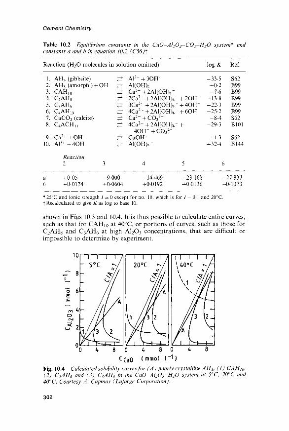
Cement Chemistry
Table 10.2 Equilibrium constants in the CaO-Al2O3~CO2-H2O system* andconstants a and b in equation 10.2 (C56)]
Reaction (H2O molecules in solution omitted)
1. AH3 (gibbsite) ^2. AH3 (amorph.) + OH~ ^3. CAH10 ^4. C2AH8 ^5. C3AH6 ^6. C4AH19 ^7. CaCO3 (calcite) ^8. C4ACHH ^
9. Ca2+ + OH- ^10. A1 3 ++4OH- ^
Reaction2 3
a +005 -9000b +00174 +00604
Al3+ + 3OH~A1(OH)4-Ca2++2A1(OH)4-2Ca2+ + 2Al(OH)4-3Ca2 ++2Al(OH)4-4Ca2 ++2Al(OH)4-C a 2 + + C O 3
2 -4Ca2 ++2Al(OH)4-
4 O H - + C O 32 -
CaOH+A1(OH)4-
4
-14-469+00192
+ 2OH"+ 4OH-+ 6OH"
+
5
-23-168+0-0136
l o g *
-33-5+0-2-7-6
-13-8-22-3-25-2
- 8 4-29-3
+ 1-3+324
Ref.
S62B99B99B99B99B99S62B101
S62B144
6
-27-837+0-1073
* 25°C and ionic strength 7 = 0 except for no. 10, which is for 7 = 0 - 1 and 20°C.f Recalculated to give K as log to base 10.
shown in Figs 10.3 and 10.4. It is thus possible to calculate entire curves,such as that for CAHJ0 at 40°C, or portions of curves, such as those forC2AH8 and C3AH6 at high A12O3 concentrations, that are difficult orimpossible to determine by experiment.
Fig. 10.4 Calculated solubility curves for (A) poorly crystalline AH3, (1) CAHW,(2) C2AH8 and (3) C3AH6 in the CaO~Al2O3-H2O system at 5°C, 20°C and40°C. Courtesy A. Capmas (Lafarge Corporation).
302
Calcium aluminate, expansive and other cements
Degrees of supersaturation relative to specific hydrates may also becalculated. The solubility curve of CAHio is more markedly dependenton temperature than are those of C2AH8 or C3AH6. At 5°C, a solutionobtained from CA rapidly becomes highly supersaturated in CAHio, butmuch less so in C2AH8 or AH3, but with increase in temperature thissituation changes; thus CAHio is the major product at 5°C, but isundetectable above 30°C (C56). At 50°C, supersaturation is high only inC3AH6, which is rapidly formed.
Barret and Bertrandie (B99,B100,B145) explained the maximumconcentrations reached in the CA-water reaction and the path bywhich they were attained. On contact with water, CA was assumed todevelop a hydroxylated surface layer, termed CAsh, of compositionCa[Al(OH)4]2, which dissolves congruently and is continuously regener-ated as new areas of surface are exposed. The maximum values reachedby the CaO and A12O3 concentrations were considered to represent thesolubility of CAsh. A solubility curve was thus calculated for CAsh, and isincluded in Fig. 10.3. The path of increasing concentrations was shown topass along a narrow corridor on the Ccao~C\i2o3 diagram, enclosingcompositions for which neither AH3 nor C2AH8 is rapidly precipitated.These phases were immediately precipitated on passing beyond the low-CaO and high-CaO boundaries of the corridor respectively. The path wasshown to correspond to a series of compositions for which the conflictingtendencies to precipitate AH3 and C2AH8 were as far as possibleminimized. The hydration of Ci2A7 was considered in a similar way. TheCAsh postulated in this approach could possibly be identified with one ofthe amorphous intermediate phases that have been reported, but thelatter appear in all cases to be more substantial than a surface layer andare in other respects not taken into account. Further work is needed inorder to relate the results of the various investigations.
10.1.6 Setting times; mixing and placingThe setting times of most CACs pass through a maximum at 25-30°C(Fig. 10.2). The effect has been observed with white CACs and with pureCA as well as with Ciment Fondu, and thus does not depend on thepresence of phases other than CA (B140). The setting time usuallyshortens between 0°C and about 20°C, but at 28-30°C it can be up to 8times as long as at 20°C. Above 30°C, it £gain shortens very rapidly. Itappears that at 28-30°C neither CAH10 nor C2AH8 forms readily, andthat C3AH6 can only form from one or other of these phases. Severalhypotheses based on difficulties of nucleation, protective coatings or bothhave been proposed (B140,C59,S115). The effect is not of practicalimportance for the setting of normal concrete mixes except possibly in thesurface zone, because the heat evolved on hydration increases the tem-perature to more than 30°C.
The length of the induction period decreases with the C/A ratio in thesolution, which is in turn affected by the presence of Q2A7 (B99). Forratios up to 106, given by pure CA, it can be as long as 6-12 h, but atratios above 1-20, immediate setting can occur. The mechanism and
303

Cement Chemistry
products of hydration of C12A7 are essentially similar to those for CA,but, as might be expected from the higher C/A ratios in the solution, theproducts do not include much CAH10, even at 4°C (E6).
Increase in energy or time of mixing markedly accelerates thehydration of CACs, and if excessive can even cause quick setting in themixer. Once mixing stops, progressive thickening occurs. Samples of agiven paste mixed for different times can behave very differently duringplacing. This factor is often forgotten, and can lead to the addition ofmore water during placing, with a consequent increase in porosity anddecrease in strength. The rheological properties of the fresh pastes(B146,C60) and (-potentials of suspensions (Z13) are broadly similar tothose found for Portland cements (Sections 8.1 and 11.4.3). As withthe latter, the water demand can be decreased by adjusing the particlesize distribution. Factors affecting choice of w/c ratio are discussed inSection 10.1.8.
10.1.7 Microstructural developmentCottin (C58) studied pastes of Ciment Fondu, largely by the TEM replicamethod. The microstructures of pastes of low w/c ratios hydrated for 7days at 12°C were too compact to show more than occasional detail, butwith pastes of w/c = 0-7 much detail could be observed in cavities exposedby fracture, which were lined with small crystals of CAHi0 andsometimes contained plates of C2AH8. The crystals of CAHi0, whichwere hexagonal prisms up to 1 fim long and 0-2 (im wide, were present inrounded aggregates. Hydrous alumina was seen in a paste of w/c= 10hydrated at 30°C; it occurred in the lining of a cavity, mainly as roundedmasses of randomly oriented platelets. Secondary electron imagesobtained in the SEM give similar results (H68,M103) (Fig. 10.5).
Backscattered electron images (H68,L52,S11) confirm and extend theseresults. Scrivener and Taylor (SI 1) reported an SEM and XRD study ofpastes of a white CAC consisting mainly of CA and gehlenite, with minorperovskite. The clinker grains were mostly polymineralic. At 5°C, theearliest process detected was dissolution of CA, with deposition ofCAHio in the outer product. Later, the inner product described in Section10.1.4 was also observed. At 40°C, these processes were followed by whatappeared to be successive formation of C2AH8 and AH3 from CAH10
and of C3AH6 and AH3 from C2AH8. Both of these latter processesappeared to occur by dissolution and reprecipitation. The C2AH8 oftenformed aggregates of plates similar to those shown in Fig. 10.5B. TheC3AH6 characteristically occurred as aggregates of equidimensionalnodules, individually about 200 nm in diameter, which were mixed on orbelow a micrometre scale with flakes of AH3. The latter phase alsooccurred in larger regions, which were apparently structureless and,rarely, as pseudomorphs after C2AH8. Some C2ASH8 was detected.
Broadly similar results were obtained for a 60-year-old field concrete,made with Ciment Fondu (C61,H70). The concrete was a pile that hadbeen knocked over and was lying on its side in an estuary, where it hadundergone repeated wetting and drying from the tide. It had probably
304

A
Fig. 10.5 SEM secondary electron images of the fracture surface of a pasteof Ciment Fondu (w/c = 0-4) hydrated for 22 h at room temperature, showing (A)
O, and (B) plates ofC2AH8. Courtesy D. Sorrentino (Lafarge Corporation).
305

Cement Chemistry
been made at w/c = 0-6-0-7 and a cement content of 300 kg m~3. The corematerial had converted, and image analysis indicated a volume porosityof 17%. The surface zone had a porosity of only 3-4% and wassubstantially unconverted. The river water contained Cl" and SO^",which had very minor effects that are noted in Section 10.1.11. An SEM,DTA and XRD study of Ciment Fondu pastes (H70) gave similar results.
The 27-year-old Ciment Fondu concrete shown in Fig. 10.1 had beenmade at a total w/c ratio of 0-32 (C61). The cement had largely reacted,apart from some large grains. Within the latter, some of the material inthe regions of CA is darker than the rest, and is possibly inner product.Elsewhere in the paste, the partly or completely reacted cement grains areless clearly distinguishable from the outer or undesignated product thanin typical Portland cement pastes, though some of the areas of denser andmore uniform appearance, such as that marked B, are probably grainsthat have reacted completely apart from pinhead regions of ferrite. Thereare some well-defined areas of AH3. These apart, X-ray microanalysesmostly appeared to correspond to mixtures of C3AH6 and AH3 on a scaletoo fine to be resolved by this method (L52).
In the white cement and 60-year-old specimens described above, thesurface zone had a more compact, less porous appearance than the bulkmaterial. In the converted white cement paste, the porosity appeared tobe unevenly distributed on a scale of some 50 /zm. The mature CimentFondu concrete of w/c ratio 0-32 showed little porosity detectable in abackscattered image, even in material far removed from the surface.
10.1.8 Hardening; effects of conversionCACs harden rapidly as soon as the massive precipitation of hydratesbegins. Relatively high proportions of water are taken up in thehydration reactions, the theoretical w/c ratios needed for completehydration of CA being 114, 0-63 and 0-46 for the formation of CAH10,C2AH8 + AH3 and C3AH6 + 2AH3 respectively. For this reason, and alsobecause of the rapid heat evolution, care is needed to avoid surfacedrying. In blocks of concrete more than 300 mm thick, the temperaturerise is sufficient to cause rapid formation of C3AH6 during hardeningunder normal conditions, though a surface zone may remain uncon-verted. Strong bonds are formed with limestone aggregates (B147,F48),apparently due to formation of C4ACHn, and with synthetic aggregateshigh in A12O3, which give high abrasion and corrosion resistance (G92).
Calculation based on the relevant densities shows that when CA hydratesto form CAH10, the volume of the latter is 3-64 times that of the CA fromwhich it was formed. For hydration to give C2AH8 and AH3 (density2.44 kg m~3), the corresponding factor, is 2-31 and for hydration to giveC3AH6 and AH3 it is 1 -73. Conversion of CAH10 into C3AH6 and AH3 thusentails a 53% decrease in volume. The porosity of the paste thereforeincreases and the compressive strength decreases. Figure 10.6 shows someresults for Ciment Fondu pastes. The importance of the changes increasesmarkedly with the w/c ratio. This has been explained thus (R62). At highw/c ratios, all the CA can hydrate to give CAH10; the changes are
306

Calcium aluminate, expansive and other cements
160
-£ 120
80
on00
or
o40
UNC.\STR>
CALC.HUNC.P O R ^
\ OBS.V UNC. '
20
0-8
Fig. 10.6 Compressive strengths and observed and calculated porosities for pastesof Ciment Fondu of varying w/c ratios. The unconverted paste, which containedCAHW, was cured for 7 days at 10°C. The converted paste, which contained C3AH6
and AH3, was cured for 7 days at 70° C. After G91.
relatively large, and the converted materials are weak and porous. At lowratios, there is insufficient space for all the CA to react to form CAH10.When conversion occurs, much water is released, so that even if the porescontain no water, more CA can hydrate. This partially compensates forthe effects of conversion, and, along with the low w/c ratio, ensures thatthe converted materials are strong and of relatively low porosity.
The rate of conversion at a given temperature is reduced if the RH fallsbelow saturation. The temperatures during setting and curing also have alarge effect; if they are high, subsequent conversion occurs more rapidly,even though the temperature is then low (C55). This is probably due tothe presence of nuclei of C3AH6. The strength after conversion is affectedby the rate at which that process occurs, perhaps because of the effect on
307

Cement Chemistry
C3AH6 morphology (Ml06). Strength may also be affected by thecrystallization of AH3, which could reduce its pore-filling capacity andefficacy as a binder. The size of the C3AH6 crystals increases with thetemperature at which they are formed; this may decrease strength. It hassometimes been said that C3AH6 is an intrinsically weak binder, but thisis not correct. As with relatively dense, crystalline substances in general(F40), it gives lower strengths than less dense substances at highporosities, but higher ones at low porosities. This may be seen from thecrossing of the curves in Fig. 10.6. Hot-pressed pastes of CACs, in whichthe binder is C3AH6 and the porosity has been reduced to about 4%,show strengths of up to 480 MPa (Section 11.9.1).
Figure 10.7 shows the results of some long-term tests of compressivestrength. The initial, rapid increase, due to formation of CAH10, isfollowed by a decrease due to conversion and, ultimately, by an increasedue to continuing hydration. It is implicit in such results that designshould be based on the assumption that conversion is inevitable, and thattests using accelerated curing should be be carried out to determine thelong-term minimum strength (B148,C61,G92,G93). A rapid increaselevelling off at this value should be assumed. For satisfactory strengthand durability, the total w/c ratio (i.e. that including water sorbed by theaggregate) must not exceed 0 4 and the cement content must be at least400kgm~3. At this cement content, a total w/c ratio of 0 4 typicallycorresponds to a free (i.e. effective) ratio of about 0-33. Because of theself-heating effect, the long-term minimum strength is commonly reachedwith such mixes within a few hours.
Conversion and its practical implications have been widely studied butnot always well understood. Thus, concretes made with inadequate
AGE —7DAYS
1 3 6MONTHS
1 2 3 5YEARS
10 20
Fig. 10.7 Long-term compressive strengths of Ciment Fondu concretes cured for24 h in moist air at 18C and then stored outdoors in southern France. After G92.
308

Calcium aluminate, expansive and other cements
cement contents and excessive w/c ratios have failed in structuralapplications. An extensive investigation in the UK into calciumaluminate concrete in existing buildings (B148) showed that a highlevel of conversion was generally reached in a few years, causing a veryvariable loss of strength, but that this loss was in most cases insufficient toendanger the structure. No adverse effects of corrosion on steel tendonsremoved from prestressed concrete beams in normal buildings weredetected. The use of CACs in structural work is nevertheless not deemedto satisfy the current (1996) UK Building Regulations. In France,prohibitive restrictions were for a time placed on its use in the publicsector of the construction industry, but in 1968 a new set of rules wasissued after lengthy studies. Current French regulations (Ml07) specifythe maximum total w/c ratio of 04 and minimum cement content of400kgm~3 mentioned above.
Conversion is of only minor importance for the use of CACs inrefractory applications and in mixes with Portland cement such as thosedescribed in Section 10.1.10.
10.1.9 Chemical admixturesMany inorganic salts affect the setting times of CACs and are effective inconcentrations around 0-5% (C62,L6,R58). The effects on setting timesdiffer greatly both in direction and in relative magnitudes from thoseobserved with Portland cements (Section 11.5.1). The results of differentinvestigators show apparent discrepancies, and the effects probablydepend greatly on concentration, which may even reverse their direction,but there is general agreement that Li+ salts and alkali or calciumhydroxides are strong accelerators and that many common inorganicsalts retard. As with Portland cement, hydroxylic organic compounds,such as sugars or citric, tartaric or gluconic acids, are powerful retarders.
Rodger and Double (R58) studied the effects of several admixtures,particularly LiCl and citric acid, by XRD, conduction calorimetry andsolution analyses. The samples were slurries of a Ciment Fondu hydratedat 22°C and in the absence of admixtures gave CAH10 as the mainproduct. In the mixes with LiCl, C2AH8 was the main product and a littleLi2O'2Al2O3'11H2O was detected. The authors considered that thiscompound acted as a nucleation substrate for C2AH8. The very lowconcentrations in which the organic compounds are effective suggeststhat, as with Portland cement, they act by poisoning the nuclei of thehydration products, but the authors found this hypothesis incompatiblewith the observed solution compositions.
An experimental study of the CaO-Al2O3-H2O system in the presenceof NaOH showed that at a concentration of lmmoll"1 the latter hadnegligible effect on the equilibria, but that at lOmmolT1 the solubilitycurves were displaced to lower CaO and higher A12O3 concentrations.At 100 mmol I"1, the solutions were very low in CaO, and precipitation didnot occur within 28 days (P51). The effect of OH~ ion on the solubilitycurves can also be calculated by an extension of the procedure mentionedin Section 10.1.5 (B100). The results showed large shifts in the curves at an
309

Cement Chemistry
NaOH concentration of 40mmol I"1, the minimum in CaO concentrationon the C2AH8 curve at 21°C being shifted from CCaO= 6-8mmolkg~1,C A i ^ ^ ^ S m m o l k g - 1 to C C a o= Mmmolkg"1 , CA 1p3~ Hmmolkg"1 .An experimental study on the effects of adding sodium phosphates ofvarious types has been reported (B149).
Other types of admixture used with CACs include water reducers andsuperplasticizers (Section 11.4), which also act as retarders, andthickening agents, such as carboxymethylcellulose. Complex formula-tions may be used for special purposes, e.g. a ready-mix mortar for high-performance road repair might contain 55% Ciment Fondu and 45%sand, with glass fibre, Al powder, Li2CO3, Na gluconate and methyl ethylcellulose (M108).
10.1.10 Mixtures with calcite, slag, gypsum or Portland cementCussino and Negro (C63) reported that loss of strength in CAC mortarscould be prevented by using calcareous aggregates o rby adding finelyground calcite to the cement. They showed that C4ACHn was formedand concluded that this limited or prevented conversion. Fentiman (F49)confirmed the formation of C4ACHn but found that at 25°C or belowCAH10 was still thejnain product and that conversion was delayed butnot prevented. C4ACHn seems to form at the expense of C2AH8 andC3AH6 at 25-60°C but to be unstable at or above 60°C (F49,M109).Strong concentration gradients and other local inhomogeneities (B150)may explain some of these apparently contradictory results. Equilibriainvolving C4ACHn have also been approached theoretically(B101,B102,D36,S75). Barret et al (B101,B102) concluded that CaCO3
would dissolve giving Q A C H n only at partial CO2 pressures above acertain value, but that equilibrium with atmospheric CO2 would not bereached within the pores of a concrete.
Majumdar et al. (MHO) studied concretes containing equal masses ofCiment Fondu and ggbs. On water curing at either 20°C or 38°C, thecompressive strengths continuously increased over a period of 1 year,whereas those of control samples made without the slag showed thenormal decreases associated with conversion. Parallel studies on pastesshowed that the superior behaviour of the mixes with slag were associatedwith formation of stratlingite.
Various combinations of CACs with calcium sulfate, Portland cementand in some cases calcium hydroxide are commonly used to makecements that set and harden rapidly. They may also dry out rapidly, dueto the absorption of water in formation of ettringite. Some such mixturesalso show expansive behaviour (Section 10.2.1). A simple, rapidly settingmix might contain 15-20 % ordinary Portland cement, 10-30% CimentFondu, 10-25% CH and 40-60% sand. More complex formulations,containing various admixtures, are used to produce self-levelling mortars.The setting times of all such mixtures depend greatly on the relativeproportions, the characteristics of the individual cements and the mixingtime and temperature; only laboratory tests can predict the precisebehaviour of a specific mix. Figure 10.8 gives a general indication of the
310

Calcium aluminate, expansive and other cements
IOOOI
- 4 0 0
40-
10
4
1
1 1 1
\\
V \
\\FINAL
"INITIAL\ \
\ ^ ', \ ^
1
//
J
1
-
-
0 20 40 60 80 100
CIMENT FONDU (%)
Fig. 10.8 Setting times of neat pastes of mixtures of Ciment Fondu and Portlandcement. These are only general indications, as the times depend on Portland cementcomposition, mixing time, temperature and other factors. After R62.
behaviour of neat pastes made from calcium aluminate and Portlandcements. The rapid setting of the mixes high in Portland cement ispossibly caused by preferential reaction of the gypsum with the CAC, andthat of those high in CAC by the increase in pH due to the presence of thePortland cement. In addition to C-S-H and CH, the hydration productscan include C4AH13 and stratlingite. Mixes of CA with sufficiently highproportions of calcium sulfate yield ettringite (C40).
10.1.11 Reactions of calcium aluminate cement concrete withexternal agents
Concrete made with CAC is highly resistant to sulfate solutions, seawater or dilute acid solutions with pH > 4, including natural waters inwhich CO2 is the only significant solute. Resistance may extend to pH « 3if the salt formed is of sufficiently low solubility. As might be expected,resistance increases with decreasing w/c ratio and increasing cementcontent (C64).
Early work indicated that high resistance to attack is associated withrestricted penetration by aggressive species. Thus, Midgley (Mill) foundthat in massive, fully converted concrete exposed to a sufate-containingground water for 18 years, penetration with formation of a substitutedettringite was limited to a depth of about 5 mm. Surface zones of hardand almost non-porous material, of the type described in Section 10.1.7,
311

Cement Chemistry
have been very widely observed (C61,C64,H70) and probably play animportant part in restricting penetration. The zones vary in thicknessfrom a few millimetres to 25 mm, and the material in them appears oftento be largely or wholly unconverted. Observations on test specimens 15years old indicated that the permeability of the surface zone may befurther decreased by carbonation (C64).
Probably on account of the surface zone, resistance can still be highwith mixes made at what would now be considered an improperly highw/c ratio and low cement content. Thus, the concrete described inSection 10.1.7, that had been exposed to river water containing Cl- andSC>4~, was still in good condition after 60 years (C61). In this specimen,there was significant ingress of Cl~ but very little of SO4 . SomeC3A«CaCl2-10H2O had formed, and was apparently intergrown withC2ASH8, but most of the Cl" seemed to be adsorbed on the CAH10. Intest cubes in which expansion and cracking had occurred, sulfate hadpenetrated into the core material and ettringite or gypsum or both weredetected (C64).
The resistance of CAC concrete to attack by alkali hydroxide solutionsis low, especially if CO2 is also present, as can occur if the calciumaluminate concrete is in contact with Portland cement concrete andexposed to atmospheric CO2 (R63). The combined attack by CO2 andalkali has been called alkaline hydrolysis. Although more complexexplanations have been postulated, the effect seems to be explainable bythe destruction of both the hydrated calcium aluminates and the hydrousalumina by a combination of carbonation and alkaline leaching of A12O3
as A1(OH)4 ion.In contrast to the above, carbonation in the absence of alkali increases
the strength of CAC concrete (P52,R64). In sufficiently porous materialin which conversion has occurred, some of the C3AH6 reacts to givecalcite and hydrous alumina (P50), but in dense concrete the extent ofpenetration by CO2 is small, probably because the pores do not containthe water necessary to promote the reaction (R64) and because theybecome blocked by CaCO3 and alumina gel (B151). These observationssupport the general conclusion that the high resistance of dense calciumaluminate concretes to various forms of attack is at least in part due toeffects that impede or prevent the ingress of the attacking substance. Inaddition to the blocking of pores by reaction products, these effects couldinclude the rapid removal of incoming water by continued hydration.
10.1.12 Refractory castablesCastable refractory concrete can be made using Ciment Fondu for useat hot-face temperatures up to 1350°C, or using white CACs for use upto 2000°C. Refractory castables can be categorized as cement castables(15-25% CAC), low cement castables (5-10%) and ultra-low cementcastables having proprietary formulations that include under 5% ofcement, silica fume and other admixtures. Depending on the servicetemperature and application, aggregates include exfoliated vermiculite,chamotte, sintered bauxite, brown or white fused alumina, chromite, etc.
312

Calcium aluminate, expansive and other cements
A very simple formula for a wall more than 50 mm thick and for use at ahot-face temperature up to 1650°C might contain 14% of 70% A12O3
cement', with 86% of a suitably graded aggregate of brown fusedalumina and 0-2% of trisodium citrate on the mass of cement; the w/cratio must be determined by an empirical test, as for a rapidly hardeningmix, but would be <0-4.
When the concrete is heated, the hydration products undergoconversion and dehydration. The strength decreases to a minimumvalue at a temperature usually between 900°C and 1100°C, though if thecement content is sufficiently high it is still sufficient for ordinaryapplications. At higher temperatures, sintering reactions occur betweenthe cement and aggregate, and the ceramic bonding that results causes thestrength and resistance to abrasion to increase. The compounds formeddepend on the compositions of the cement and aggregate, but typicallyinclude such high melting point phases as CA2, CA6 and spinel (MA).
10.2 Expansive cements10.2.1 GeneralA normal Portland cement concrete expands slightly during moist curing,but this effect is outweighed by the drying shrinkage that occurs onsubsequent exposure to an atmosphere of normal humidity. If theconcrete is restrained, the resulting tensile stress may be sufficient to crackit. In an expansive cement, the expansion is increased, so as to balance oroutweigh the subsequent contraction. Expansive cements, which werefirst described by Lossier (L53), may be categorized as shrinkage-compensated or self-stressing cements.
In a shrinkage-compensated cement, the object is to balance the dryingshrinkage to prevent cracking. In practice, the expansion is restrained byreinforcement and a small compressive stress of 0-2-0-7 MPa is created inthe concrete, which should preferably remain under slight compressionafter the normal drying shrinkage has occurred. Practical uses ofshrinkage-compensated cements have included such structures as multi-storey car parks or water storage tanks, in which it is desirable oressential to eliminate water leaks.
In a self-stressing cement, a larger expansion is produced, with theobject of achieving greater stresses in the reinforcement and the concreteto permit the production of thin, strong articles or structures, as inmechanical prestressing. Estimates of the maximum stress that can besafely achieved have ranged from 3-5MPa (Ml 12) to 8MPa (W36).Because the concrete expands triaxially, careful design and choice ofcuring conditions, including if necessary triaxial restraint, are essential.Self-stressing cements have been used both in the manufacture of precastpipes and other units and for in situ applications.
In any expansive cement, the amount of expansion and the periodduring which the expansive reaction occurs are critical. The reaction musttake place after the concrete has developed some strength, but beforeexposure to a reduced RH places it in tension, which could causeirreversible damage.
313

Cement Chemistry
10.2.2 Types of expansive cementProbably a majority of practical expansive cements have depended on themodification of a Portland cement in such a way as to increase theformation of ettringite. Single expansive cement clinkers can be made,but it has been more usual to produce admixtures that are blended orinterground with a normal Portland cement or clinker. Blending has theadvantage that the fineness of the expansive admixture can be optimized,usually by grinding it more coarsely so as to delay the expansive reactionuntil the cement has developed the necessary strength. It also allows asingle admixture to be used in differing proportions to make bothshrinkage-compensated and self-stressing cements.
In a widely used US terminology, expansive cements based on Portlandcement and calcium sulfate are categorized as Types K, M or S,according to the source of the additional A12O3 that is required. Type Kcements, developed by Klein and Troxell (K54), contain C4A3S as anessential ingredient. They are usually produced by intergrinding orblending an ordinary Portland cement clinker with additional gypsum oranhydrite and an expansive clinker containing C4A3S. The compositionof the expansive clinker can be varied considerably to utilize the rawmaterials most economically available; the clinkers made in the USAtypically contain 8-50% of C4A3S with some anhydrite and usually somefree lime (Ml 12). The proportions of expansive clinker and of gypsum oranhydrite or both that are added to the Portland cement depend on thecomposition of the expansive clinker and the degree of expansionrequired. Mehta and Polivka (Ml 12) found that Type K shrinkage-compensated cements made with Portland cement clinkers of low ormoderate potential C3A content and containing 6% or more of SO3
resisted chemical attack by sulfates, but that Types M and S cements didnot. Table 10.3 includes some analyses of Type K cements.
Type M cements contain Portland cement, a CAC and additionalcalcium sulfate. They were extensively studied in the former USSR.Mikhailov (Ml 13) described a self-stressing cement composed of Port-land cement, CAC and gypsum typically in the proportions 66:20:14and used to produce precast units. An initial cure in air followed byhot water allowed strength to be developed without formation of ettrin-gite, which occurred during a subsequent cure in cold water. Mixturesusing alumina slag as the source of the additional Al2O3 were also used,and only required curing in air followed by cold water (M112,M114).
Table 10.3 Compositions(Ml 12)
Application
Shrinkage compensationShrinkage compensationSelf-stressing
of Type K expansive
MgO
0-7342-7
A12O3
4-85-784
SiO2
21-618-814-6
cements
SO3
6-26-5124
produced
CaO
62461457-6
Fe
211
in
2o
•8•9•6
the USA
3 Loss
1-11-51-9
314

Calcium aluminate, expansive and other cements
Mixtures of CAC with gypsum (X4) or with gypsum and C4AH13, thelatter made from CAC and lime (Ml 13), have also been employed.
Type S cements are Portland cements high in C3A and with suitablecontents of calcium sulfate; they have found little favour as too difficultto control. The A12O3 has also been supplied in forms other than thosementioned above. Impure alunite (KA13(SO4)2(OH)6), which occurs as anatural rock, has been used, either after calcination (V9) or uncalcined(W36). In the latter case it was mixed with Portland cement clinker,anhydrite and flyash or slag and was found to dissolve relatively slowly,thus suitably delaying the expansive reaction.
The possibilities of using free lime or periclase as expansive agents havealso been investigated. Kawano et al (K55) and Long (L54) describedclinkers in which substantial proportions of free lime are present asinclusions in alite. In both cases, the raw mix included anhydrite. Longinvestigated and described the processes by which this microstructurewas formed.
10.2.3 Mechanism of expansion in Type K cementsIn a Type K cement, the formation of ettringite from C4A3S may berepresented by the equation
C4A3S + 8CSH2 + 6CH + 74H2O -* 3C6AS3H32 (10.3)
Consideration of the relevant densities shows that the solid volume isapproximately doubled, and it has sometimes been assumed that this issufficient to explain the expansion. However, as the case of the normalhydration of Portland cement shows, a doubling of the solid volume doesnot necessarily cause significant expansion. The change in porosity mustbe considered, and depends on the extent to which the particles of theproduct are accommodated in the existing pore structure. Any adequatetheory of the mechanism of an expansive reaction must be based on anunderstanding of the microstructure.
Odler and Jawed (O25) reviewed expansive reactions in concrete,including those produced through the use of expansive cements. Probablya majority of workers have accepted the view of Lafuma (L55) thatexpansion results from forces exerted by the growth of the ettringitecrystals. Of other theories, the most significant in relation to Type Kcements is that proposed by Mehta (Ml 15), who attributed it to attrac-tion of water molecules to ettringite crystals of colloidal dimensions.
Benturand Ish-Shalom (B152,B153,I13,I14) studied mixtures ofC4A3S, CS and CH in pastes, alone or mixed with C3S. Expansion didnot begin until a certain critical degree of reaction, which was about 50%at 20°C, had been reached. Using SEM, light microscopy and mercuryintrusion porosimetry, they confirmed earlier observations that theettringite was formed as porous coatings around the grains of C4A3S,which were thus effectively caused to expand; expansion began when theexpanding particles came into contact and exerted pressure on each
315

Cement Chemistry
other. In the absence of restraint, these particles could be treated asspheres, but under restraint they expanded in the directions in which therestraining forces were least. Essentially the same mechanism wasdescribed by Ogawa and Roy (017,026), who found that the ettringitewas formed initially as very small, unoriented crystals. After the degree ofreaction (defined by the quantity of ettringite formed) had reached about50%, the ettringite developed as radial growths of longer crystals.Contact between the ettringite layers surrounding the C4A3S particles,and the associated expansion, began only after this stage had beenreached. The change in ettringite morphology was considered to be animportant first step in causing expansion.
One study on Type K cements showed no significant dependence ofettringite crystal size on the Ca2+ concentration in the solution (K56). Incontrast, other investigators have found that suspensions of C4A3S, CSand CH at high CaO concentrations give ettringite in the form of a fine-grained coating on the C4A3S particles, but that in the absence of CHthe ettringite forms long, thin needles (M115,N19,O27). In pastes con-taining C4A3S, expansion occurs if CH is present but not if it is absent,even though ettringite is still formed (N19,O27). This parallels the beha-viour of supersulfated cements (Section 9.2.10), which yield muchettringite and no CH, and do not expand significantly.
The effect of CH in favouring expansion is explained on Mehta'stheory by the decreased crystal size of the ettringite (Ml 15). On thecrystal growth hypothesis, it is explained by the differing microstruc-tural location in which the ettringite is formed (N19,O27). If the CaOconcentration in the solution js high, Al(OH)^ ions cannot migrate farfrom the surface of the C4A3S, and the ettringite is precipitated on thesurface of that phase. Very high degrees of super saturation maybe reached locally at that surface, and, since the pressure that can beexerted by a growing crystal increases with the degree of super-saturation, strong expansive forces can be produced. The stresses maybe further increased by the fact that ettringite formation is concentratedinto a relatively few places. The crystals are small due to the highdegree of super saturation. If the CaO concentration is lower, A1(OH)4ions can migrate more freely and the ettringite is precipitated moreevenly throughout the material, under lower supersaturation. The lowerdegree of supersaturation would also explain the increased size ofthe crystals.
The balance of the evidence favours the hypothesis that expansion inType K cements is caused by crystal growth. It is also difficult to see whyettringite crystals of the size postulated by Mehta (~l/ im in longestdimension; Ml 15) should attract water more strongly than C-S-H gel,which has a very much greater specific surface area. However, the samemechanism does not necessarily operate in other cases of expansionassociated with ettringite formation, including even other types ofexpansive cements. For expansion caused by external sulfate attack(Section 12.5) or by delayed ettringite formation (Section 12.6), there issome reason to suppose that it does not.
316

Calcium aluminate, expansive and other cements
10.3 Other cements10.3.1 Very rapidly hardening cementsVarious methods have been used to obtain cements that set and hardenrapidly. They include the use of Portland cement with admixtures and ofmixtures containing both Portland and CACs, described in Sections 11.5and 10.1.10 respectively. Another approach hasj)een the manufacture ofclinkers containing either CnA7«CaF2 or C4A3S, both of which hydraterapidly under appropriate conditions with the formation of ettringite.
Regulated-set cement and jet cement are modified Portland cements inwhich the normal aluminate phase is replaced by CnA7«CaF2 throughthe use of a raw mix containing CaF2. Uchikawa and co-workers(U22,U23) gave chemical (Table 10.4) and phase compositions of twojet cements. Both contained approximately 60% of alite, 20% ofCnA7'CaF2, 1% of belite and 5% of ferrite. Admixtures were requiredto control the rate of reaction of the CnA7 • CaF2 and the nature of theproducts. One of the cements included a proprietary retarder based oncitric acid, together with 2% of CaCO3. The other contained 2-5% ofhemihydrate. In each case, Na2SO4 (1%) and anhydrite were also present.The specific surface areas were around 550 m2 kg"1.
Uchikawa and co-workers (U22-U24) studied the hydration reactionsof CnA7'CaF2 and jet cements, including the effects of variousadmixtures. A wide variety of methods was used. For the two cementsmentioned above, hydrated in pastes at 20°C, the main product at 3 h wasettringite. At this stage, 40-45% of the CnA7-CaF2 had reacted. SEMshowed needles of ettringite, 0-5-1 0/xm thick, growing from the particlesof clinker and anhydrite to form a closely knit, interlocking structure.Comparable mortars of the same age had compressive strengths ofaround lOMPa. The quantity of ettringite formed was such that a highproportion of the anhydrite must have reacted. Subsequently, the contentof ettringite tended to decrease slightly and some monosulphate wasformed; the ettringite recrystallized, giving larger crystals. The alitehydrated to give C-S-H; calculations based on assumed reactionstoichiometry indicated that the reaction was much faster than in aPortland cement, with about 65% reacting in 1 day. The compressive andbending strengths increased rather slowly between 3h and 24 h, butthereafter more quickly, and by 7 days the former were 32-44 MPa. Thetype of retarder (citric acid or hemihydrate) considerably affected thehydration reactions and the pattern of strength development. Thefluoride ion was believed to enter an aluminium hydroxide fluoride.
Cements that set and harden rapidly can also be made in which theprincipal constituents are C4A3S and belite. Table 10.4 includes thechemical composition of a clinker described by Sudoh et al (SI 16). Theclinker, made from limestone, by-product gypsum, aluminous materialsand clay, was burned at 1300°C. The presence of a limited amount of freelime was found to be necessary to achieve rapid strength development,and conditions such that all the SO3 was bound as C4A3S were requiredto avoid atmospheric pollution. The phase composition was given asC4A3S, 54%; C2S, 32%; C4AF, 5%; free lime, 9%. The clinker was
317

Tab
le 1
0.4
Che
mic
al a
nd p
hase
Mat
eria
l N
a 2O
Jet
cem
ent
0-6
Hig
h st
reng
th (
clin
ker)
-
com
posi
tions
MgO 0-8
of r
apid
ly
A1 2
O3
110
28
1
hard
enin
g
SiO
2
13 9
112
mat
eria
ls
SO
3
111
71
cont
aini
ng
K2O
04
CJJ
A7
CaO 58
95
20
• C
aF2
or C
4A3
Fe 2
O3
1-7
1-6
F 10
Los
s
0-2
Ref
U22
S116
O 1 I S CD

Calcium aluminate, expansive and other cements
interground with by-product anhydrite to a specific surface area of400 m2 kg"1; the optimum molar ratio of total SO3 to A12O3 was found tobe 1-3-1 -9 (20-25% SO3). XRD and SEM of 1-day-old pastes showed themain product to be ettringite, the needles of which were 1-2//m longand formed an interlocking network. A mortar made with the cementcontaining 20% SO3 developed compressive strengths of 27 MPa at 3 h,49 MPa at 1 day and 59 MPa at 28 days. The strength development atlater ages was attributed to hydration of the C2S.
For supporting and sealing the walls of roadways in coal mines, amaterial is required that can be transported as a slurry which remainsstable for long periods while stationary in a pipeline but which whenplaced develops a modest compressive strength within a few hours. Thiscan be achieved by employing two slurries that react and harden on beingmixed. In one such system, one slurry contains a clinker containingC4A3S and the other contains anhydrite, CH, bentonite and alkali metalsalts (L56). The C4A3S clinker, which can also be used as an expansiveadmixture with Portland cement, hydrates only slowly in the absence ofCH. In the second slurry, the bentonite keeps the other solids insuspension and the alkali metal salts act as accelerators. In anothersystem (B154), one slurry contains a CAC and the other anhydrite,bentonite, gypsum, lime and Li2CO3. In both cases, the products includeettringite and are of very high water content.
In most of the cements described in this section, ettringite is animportant hydration product, but, as in supersulfated cements, itsformation does not cause significant expansion. It is presumably formedeither at a stage when the matrix of other phases is readily deformable orunder conditions that allow it to be accommodated in an existing porestructure without causing disruption.
10.3.2 Energy reduction in the manufacture of cementsEnvironmental pollution, including the emission of CO2, and thedepletion of resources of fossil fuels and raw materials are among themost serious problems confronting humanity today. Locher (L57)reviewed ways of decreasing the energy consumption in cementmanufacture to values substantially below those characteristic ofmodern Portland cement production. They included the use of fluxes tolower the burning temperature, the production of cements containingmore reactive forms of belite or based on belite together with highlyreactive phases, replacement of alite by the chloride-containing phase,alinite, and the use of composite cements.
The burning temperature for production of Portland cement clinkercan be decreased by about 150 K through the use of fluxes, but opinionshave differed as to the energy saving thereby obtainable. Klemm andSkalny (K57), who reviewed the subject, estimated it at 630kJkg~1.Christensen and Johansen (C65) considered that this figure, whilepossibly realistic for an inefficient, wet-process kiln, was unlikely to beso for a modern precalciner-preheater kiln, in which heat recovery isefficient. They considered a value of 105kJkg-1 more realistic.
319
Cement Chemistry
The compositions of many waste materials, such as slags, limit theextent to which these can be used in the production of a normal Portlandcement clinker, but a wider range or higher content of waste materialsmight be usable in making other types of clinker. Mehta (Ml 16) noted thepossibility of using by-product gypsum, red mud (from aluminiumextraction), slag and flyash in producing high-iron cements (Section10.3.4). Some limestones unsuitable for making a normal Portland cementclinker could be used to make clinkers higher in belite. Burning at areduced temperature might be expected to decrease the formation of NO*.
In appraising the energy savings obtainable with these or other newtypes of cement, it is essential to consider the total energy requirements,from the winning and transport of the raw materials onwards. Locher(L57) emphasized the further need to consider not only strengthdevelopment but also the durability obtainable given the curingconditions likely to be used in practice. He concluded that, with thelow-energy cements that had then been investigated, the energy savingswere probably no greater than those which could be achieved by use ofcomposite cements containing slag, flyash, natural pozzolanas or fillers,the behaviour of which was well understood.
10.3.3 Reactive belitesIn the past few decades, very substantial improvements in energyefficiency in the production of Portland cement clinker have been made,and while further improvements may be expected, the possibilities ofenergy saving by this means are inevitably limited. The major componentof the enthalpy change in the formation of Portland cement clinker arisesfrom the decomposition of calcite, and a large saving could be achieved ifthe proportion of belite could be increased and, ideally, the formation ofalite avoided. The theoretical heat requirement would be less and theclinkering temperature could probably be lowered. Because of the lowerCaO content, the proportion of limestone would be reduced, less CO2
would be produced and, possibly, limestone of lower purity could beused. In addition, the decreased quantity of CH formed on hydrationmight be expected to improve durability. The outstanding difficulty is thelow rate of reaction of belite and thus also of strength development.
Methods for producing highly reactive belite or cements high in belitehave recently been reviewed (C66). Attempts to increase the reactivity ofbelite have rested mainly on stabilization of the higher-temperaturepolymorphs, decrease in crystallinity or crystallite size, or combinationsof these. Thus, reactive forms of belite have been obtained in the labora-tory by low-temperature methods (R65,V10), but it is not clear how thelatter could be effectively utilized in practice. Rapid cooling of a clinker(e.g. at lOOOKmin"1) increases the reactivity of belite, at least in part bypreserving the a'-polymorph (G94,S117) and may offer a more practicalapproach. Hillebrandite (Ca2(SiO3)(OH)2) may be prepared hydrother-mally from lime and silica at 200-250°C, and dehydrated at 500°C to givea form of /3-C2S having a high specific surface area, which hydrates
320

Calcium aluminate, expansive and other cements
rapidly in pastes-at 25°C (115,116,028). The hydration product is C-S-Hhaving a Ca/Si ratio close to 20, so that little or no CH is formed.
10.3.4 Cements containing belite and a highly reactive constituent.In another approach to the problem, cements have been devised thatcontain belite together with a constituent, usually C4A3S, which reactsrapidly and thereby provides sufficient early strength. Some have beenproportioned in a way designed to produce rapid setting and hardening;an example is given in Section 10.3.1. Some other examples of cementsbased on belite and a highly reactive constituent are as follows.
(1) An alumina-belite cement (Z14) was obtained by burning at1300°C of a mix intermediate in composition between those ofPortland and calcium aluminate cements, with some gypsum. Itcontained 62-64% of belite, with CA, C12A7, C4A3S and C5S2S,and was claimed to give good strength development andresistance to sulphate attack. Porsal cement (VI1) is essentiallysimilar and was made using CaF2 as a mineralizer.
(2) Cements high in Fe2O3 have been described, containing highproportions of C2S, C4A3S, ferrite, and anhydrite (M116,W37).The hydration products of one such cement were reported to beAFt (ettringite), AFm, AH3, FH3 and C-S-H, with little CH(W37). Depending on phase composition, either normal orexpansive cements can be obtained (W37).
(3) Sahu and Majling (SI 18) described cements made by firing mix-tures of limestone, flyash and .gypsum at 1200°C. The cementstypically contained C2S, C4A3S and CS as their major constit-uents, with smaller amounts of free lime and ferrite. The phaseassemblages agreed with ones predicted from data on the CaO-SiO2-Al2O3-Fe2O3-SO3 system. The properties were broadlysimilar to those of Portland cements. Ettringite was a major earlyhydrationproduct, and appeared to form by reaction involvingthe C4A3S, anhydrite and free lime. Glasser and co-workersreviewed the hydration chemistry (W38) and the microstructureand microchemistry (A30) of cements based on C4A3S. A clinkerin which the most active phase was C4A3S had a spongy texture,making it easy to grind. Equant, well-shaped crystals of C4A3Swere embedded in a matrix consisting largely of the C2S and aphase that approximated in composition to a ferrite but waspossibly more properly described as a perovskite (A30).
10.3.5 Alinite cementsThese cements were developed by Nudelman in the former USSR andpatented in 1977. A mix for making Portland cement clinker is modifiedby adding CaCl2, which allows the maximum temperature in the kiln tobe reduced to 1000-1100°C. Table 10.5 gives some typical oxide com-positions of the clinker. The alite is replaced by alinite, a structurallyrelated phase containing essential Mg2+, Al3+ and Cl~. Bikbaou (B155)
321

Cement Chemistry
Table 10.5 Composition of alinite clinkers (A31)
MgO 2-0-2-2 CaO 62-5-63-9 Cl (free) 0-04-0-12A12O3 4-4-4-6 Fe2O3 3-6-4-8 Ignition loss 0-7-1-0SiO2 22-7-23-3 Cl (total) 1-0-2-9 Free lime <0-5
gave the phase composition as alinite, 60-80%, belite, 10-30%,CnA7-CaCl2, 5-10%, ferrite, 2-10%, and discussed the process ofclinker formation. Later work showed that a calcium chloride orthosili-cate is also present (A31). This was possibly Ca3Si04Cl2, which isrelatively highly reactive (K58). The process of formation has been furtherdiscussed (A31,B156,N20). Locher (L57) gave a survey of more generalinformation, based partly on the patent data. The preparation of the purecompound has been described (V12,M117).
The crystal structure of alinite has been determined (117,VI2). Theconstitutional formula is Ca9.9Mg0.8 • o-aCSiO^.^AlO^o^Oi^Cl, where• denotes a vacancy; limited variations in the Mg/Ca and Al/Si ratiosare possible (V12). Alinite is tetragonal, space group 142 m, witha= 1-0451 nm, c = 0-8582nm, Z = 2 , Z>x«3010kgm-3 (V12), and isisostructural with the silicate sulphide mineral, jasmundite,Can(SiO4)4O2S (D59). A Br-analogue has been prepared (K59).
The hydration reactions of alinite cements do not appear to have beenreported, but it may be surmised that they are similar to those of Portlandcements, with the probable addition to the products of C3A*CaCl2*10H2O and possibly also that of Ca2Cl2(OH)2 • H2O. The Cl~ is, however,not wholly and permanently combined in these or other hydrationproducts. In tests on reinforced concrete, serious corrosion had occurredwithin 5 years, showing the cement to be unsuitable for such use (L57).
322

11 Admixtures and special usesof cements
11.1 IntroductionAdmixtures for concrete are defined as materials other than hydrauliccements, water or aggregates that are added immediately before or duringmixing. Materials such as grinding aids that are added to cement duringmanufacture are strictly called additives, though the term admixture isoften used for these also. The most important admixtures are ones addedto accelerate or retard setting or hardening, to decrease the quantity ofwater needed to obtain a given degree of workability, or to entrain air inorder to increase the resistance of the concrete to damage from freezing.Mineral additions (Chapter 9) are not included here in either category.
Many materials have been used as admixtures and the potential ofmany more has been examined. The literature, including the patentliterature and other descriptions of proprietary materials, is voluminous,and this text will attempt only to describe the effects of the mostimportant classes of admixtures and additives in general terms and todiscuss the chemistry underlying those effects at a fundamental level.
The rest of the chapter deals with the hydration chemistry of Portlandand composite cements at temperatures outside the range of 15-25°C,including that of autoclave processes, and with specialized uses ofcements in casing oil wells and in making very high strength materials.
11.2 Organic retarders and accelerators11.2.1 RetardersAdmixtures that retard setting are of value for concreting in hot weatherand other purposes, including oil well cementing (Section 1L8). Manyorganic materials have this property; sucrose, calcium citrate and calciumlignosulfonate are examples. They are effective in low concentrations,suggesting that they act by adsorption. Taplin (T53) noted that mostcontain one or more groups in which O atoms are attached to adjacentcarbon atoms, such as -CO • C(OH)=, or are otherwise able to approacheach other closely. He also noted that adsorption on either a clinkerphase or a hydration product might cause retardation, in the latter casethrough interfering with growth. Young (Y8), reviewing the evidence,
323

Cement chemistry
concluded that adsorption on products, especially CH, was the primecause of retardation. He considered that adsorption on anhydrous phasesalso occurred and that, with pure C3A or C3S, it caused an initialacceleration by favouring dissolution.
Ramachandran et al (R41) discussed factors affecting the efficacy of aretarder with cement. They included the ratio of retarder to cement, thetime at which the retarder is added, the temperature and the composi-tions of the cement and of the mix. The time of initial set increases withthe content of retarder and generally decreases with temperature andcement content. In a typical case, addition of 0.1% of sucrose on the massof cement might increase the time of initial set from 4h to 14 h, while a0-25% addition might delay it to 6 days. Sufficiently high additions candelay setting indefinitely. Retarders are more effective with cements lowin aluminate, because the latter, or their hydration products, consumedisproportionate amounts of retarder. Some are more effective withcements low in alkali, perhaps because the latter destroys them. Retardersare most effective if added 2-4 min after mixing, because the aluminatehas by that time reacted to some extent with the gypsum and consumesless retarder. The interactions between these and other factors aresufficiently complex that the effect of a specific retarder on a given mixshould be pretested before it is used on a job. This applies to admixturesin general.
77.2.2 Mechanism of retardationThomas and Birchall (T54) obtained strong support for the hypothesisthat retardation arises from adsorption on a hydration product. They
1 1 >
~S=SUCROSE(50mmoir1)
_C=CONTROL
' • • /
I I 1
1 /
/(S)
/ca2*/ (S).
,P--°(C)
, ( 0
2 0 0 -
|i50
2100-<(X.
^ 50-
00-33 1 10 100
TIME (MINUTES)Fig. 11.1 Concentrations in the aqueous phase of Portland cements hydrated atw/c = 2-0 in water or in sucrose or EDTA solutions. After Thomas and Birchall (T54).
324
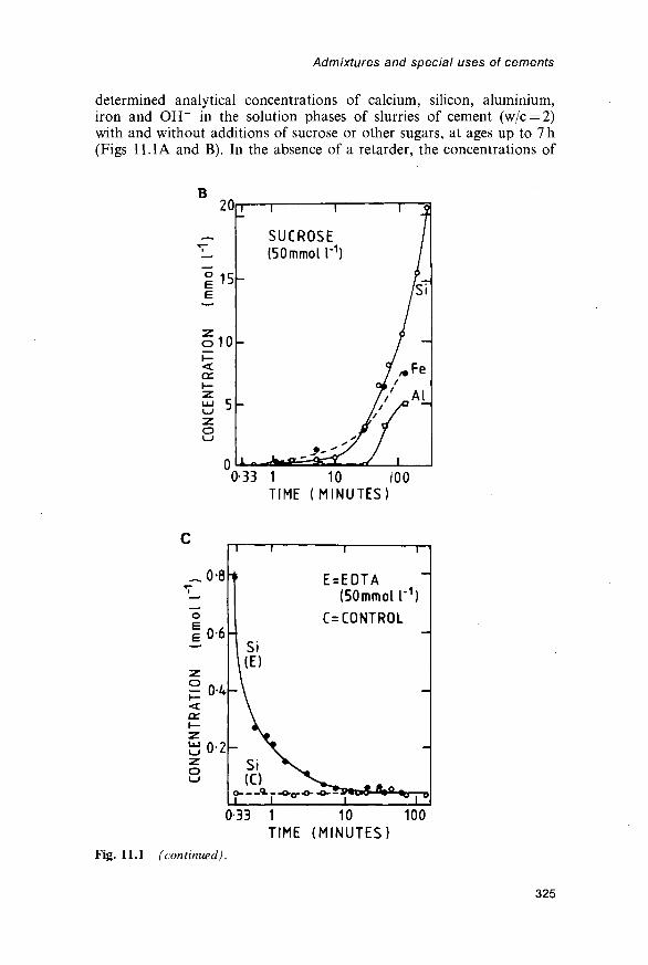
Admixtures and special uses of cements
determined analytical concentrations of calcium, silicon, aluminium,iron and OH~ in the solution phases of slurries of cement (w/c = 2)with and without additions of sucrose or other sugars, at ages up to 7 h(Figs 11.1 A and B). In the absence of a retarder, the concentrations of
B20
I 15
<ce
0
SUCROSE(50mmol I'1
1 I - - ~ "
0-33 1 10 I00TIME (MINUTES)
E=EOTA(SOmmol I'1}
C=CONTROL
I
033 1 10 100TIME (MINUTES)
Fig. 11.1 (continued).
325

Cement chemistry
silicon, aluminium and iron were all very low (Si = 0-04 ±0-01 mmoll"1,Al^OOlmmoir1, Fe<001 mmoll"1), and Ca/Si ratios were in theorder of 1000. In the presence of sucrose at 50mmoll~1, the calcium andOH~ concentrations were somewhat increased, but those of silicon,aluminium and iron were increased by factors of up to 500, so that theCa/Si ratio at 2h had fallen to 6. The results were explained (B157,T54, T55) by supposing that poisoning of the surfaces of the hydra-tion products allowed the Ca2+ ions to coexist in solution with thesilicate, hydroxoaluminate and hydroxoferrite ions at concentrations thatwere impossible if the solution was in equilibrium with the unmodifiedhydration products. NMR studies showed that Si-sucrose complexeswere not formed.
The results of a similar study in which EDTA was used in place ofsucrose further supported this conclusion (T56). The silicon concentra-tion in this case increased rapidly during the first 20 s, but soon decreasedto a value similar to that in the control (Fig. 11.1C). EDTA is a strongcomplexing agent for Ca2+ in alkaline solutions; it therefore effectivelyremoves the Ca2+ from the system, and allows the silicate ion concen-tration to increase. Because it acts in the solution and not on a surface, astoichiometric quantity (1 EDTA anion per Ca2+ ion) is required, and theeffect ceases when this is used up. Sucrose, in contrast, acts by adsorp-tion, and much less is required. In accordance with these conclusions,EDTA has a negligible effect as a retarder when used in concentrationstypical for such admixtures (T53).
Thomas and Birchall (T54) summarized and extended data on thecomparative retarding effects of different sugars. They distinguished threecategories. Trehalose and a-methyl glucoside are ineffective as retarders;both are non-reducing sugars containing only 6-membered rings. Glucose,maltose, lactose and cellobiose, which are reducing sugars containingonly 6-membered rings, are good retarders. Sucrose and raffinose, whichare outstanding retarders, are non-reducing sugars containing 5- and6-membered rings. The ability to solubilize CH was shown to be highestfor maltose, lactose and cellobiose and lowest for trehalose and a-methylglucoside, and thus does not run parallel to retarding ability. This isshown also by the behaviour of EDTA, noted above.
Experiments in which calcium oxide or hydroxide was treated with suc-rose solutions (B157) showed that a 1:1 Ca-sucrose complex was formed.It was concluded (B157,T54) that the retarding species was R-O-Ca-OH,where R represents the sucrose anion, which was incorporated into thesurface of a growing particle of CH or C-S-H, thereby inhibiting growth.The calcium was considered to be attached to the fructose (5-memberedring) part of the molecule. Trehalose and a-methyl glucoside were con-sidered to be ineffective because their ability to complex calcium is veryweak. The reducing sugars were considered to be less effective than suc-rose or trehalose because opening of the ring allowed them to chelate Ca,giving complexes that were less readily adsorbed.
Birchall and Thomas (B157) explained the inhibition of growth ofC-S-H by assuming that the Ca-O layers are the first parts of this
326

Admixtures and special uses of cements
material to be formed, and could thus be poisoned by the retarder. Taylor(T57) earlier proposed a similar mechanism for the growth of C-S-H:starting from mononuclear complexes, such as [Ca(H2O)5(OH)]+,repeated condensation through sharing of edges and elimination ofwater molecules leads to the formation of a Ca-O layer, which serves as amatrix for the formation of Si2O7 groups, and ultimately of dreierketten.He considered it unnecessary for a complete CaO2 layer to be formedbefore silicate ions can begin to condense with it. It is most unlikely thatthe Si-O parts of the structure could form before the Ca-O partsbecause, although a column or layer of linked Ca-O polyhedra can existwithout dreierketten, the reverse is not true. The manner in which thesilicate tetrahedra condense is governed by the coordination requirementsof the metal cations, and is entirely different if the Ca2+ is replaced, forexample, by Mg2+.
Jennings et ah (J38) found that with C3S, the retarding effect of sucrosewas greatest if it was dissolved in the mixing water. This contrasts withthe situation for cement. They concluded that the retarder was incorp-orated into the initial product and impeded its transformation into a secondproduct. This explanation is compatible with that discussed above ifincorporation is taken to mean adsorption on nuclei or growing particles ofthe second product. Although there may well be a phase transformation,this evidence does not seem to demand one. Even without one, the retarderwould be more effective the sooner it was added, because a smaller areawould require to be poisoned. The situation with cement differs due to thecompeting effect of the aluminate phase.
The broad conclusion indicated by the evidence considered in thissection is that organic retarders are substances that are readily adsorbedon to the surfaces of growing particles of hydration products, especiallyC-S-H, and which do so in preference to complexing Ca2+ ions inaqueous solution. The monodentate mode of attachment proposed byThomas and Birchall (T54) explains the differences in behaviour amongsugars, but its applicability in this respect to a wider range of substanceshas yet to be examined. It does not appear to account for the observationthat the effective retarders are compounds in which two oxygen atoms arelocated on adjacent carbon atoms, or are otherwise able to approach eachother closely.
11.2.3 Practical retardersThe retarders most widely used in practice appear to be hydroxy carboxy-lic acids or their salts, such as citrates or heptonates, and lignosulfonates.Because of the low concentrations required, they are commonly added assolutions. Calcium or sodium lignosulfonates are waste materials fromthe manufacture of wood pulp, when they are formed by the breakdownof lignins. Their molecules are random, three-dimensional polymers withmolecular weights of up to 50 000, probably spherical and with manysulfonate groups on their surfaces. The molecular structures are notcompletely known, and the element shown in Fig. 11.2 is purely illustra-tive of the types of local grouping that have been identified. Unpurified
327

Cement chemistry
CH3O
0
Fig. 11.2 Typical element of structure from a lignosulfonate onion.
commercial lignosulfonates contain substantial proportions of sugars andrelated salts of sugar acids, such as gluconates, which are at least partlyresponsible for their retarding properties. Differing views have beenexpressed concerning the extent of the contribution from the lignosulfo-nate molecules themselves. Milestone (Ml 18) and others have concludedthat the retarding effect with C3A is largely due to the sugar acids, butRamachandran (R66) found that, in low concentrations with cement, puri-fied lignosulfonates were almost as effective as the unpurified material.
11.2.4 Organic acceleratorsCalcium formate accelerates setting and hardening in a manner similar tothat of many inorganic salts (Section 11.5). Oxalic acid, added to C3S,increases the extent of the initial reaction, but has no significant effect onthe length of the induction period or the subsequent major stage ofreaction (O14). Calcium oxalate is precipitated, and the concentration orchemical potential of Ca2+ ions close to the surface of the C3S is therebykept low until all the oxalic acid has been used up. Triethanolamine isadded to some admixture formulations to decrease the retarding effect ofthe water reducer. The chemistry of its action is not well understood.Ramachandran (R67) found that, added as the sole admixture inamounts greater than 0 1 % , it accelerates the reaction of the aluminatephase but markedly retards that of the silicates. At 0-5%, initial setoccurs within a few minutes, but final set is delayed to over 24 h. Thisbehaviour appears to be qualitatively similar to that of glucose, whichalso accelerates the initial reaction of the aluminate phase, though itdelays the subsequent replacement of ettringite by monosulfate andgreatly retards the hydration of the silicates.
11.3 Air-entraining agents and grinding aids77.3.7 Air-entraining agentsThe ability of concrete to resist damage from freezing of the pore solutionis increased by introducing voids into which the latter can expand. Air isentrapped on normal mixing, but is then of limited value because the
328

Admixtures and special uses of cements
resulting voids are too large and too widely spaced. By the addition of asuitable surfactant, additional air is entrained and produces a stablefoam, which persists in the hardened paste in the form of closely spaced,spherical pores. Air entrainment also improves workability. To avoidundue loss of strength, the total volume of pores should not be largerthan necessary; the pores should therefore be small. The pores should notreadily fill with water if the paste is saturated; small, isolated pores aremost likely to meet this requirement. Klieger (K60) discussed the separa-tions and total volumes of pores needed to provide adequate frostresistance. Typically, the pores are 10-250 fim in diameter and the averagemaximum distance from any point in the paste to the nearest void, calledthe void spacing factor, is about 150/xm.
Air-entraining agents are characteristically long-chain molecules with apolar group at one end, which therefore become concentrated at the air-liquid interface with their polar groups in the liquid and their non-polarparts out of it. Bubbles are formed by entrapment of air, but in theabsence of the air-entraining agent are mostly destroyed because of thesurface tension of the liquid. The air-entraining agent lowers the surfacetension and stabilizes them. The inner surface of the bubble is thuscomposed of hydrophobic material formed by the non-polar parts of themolecules, which acts as a barrier to the entry of water during mixing orplacing and on any subsequent occasion when the paste is saturated.
Air-entraining agents may be simple compounds, such as sodiumsalts of fatty or alkyl aryl sulfonic acids, but some are more complex(K60). The quantity of the active ingredient used is typically in the orderof 005% on the mass of cement. As noted above, the property of airentrainment overlaps in varying degrees with the properties of retarda-tion and water reduction. Air entrainment increases the workability of anotherwise similar concrete; by allowing the w/c ratio to be decreased, thiscan partly or wholly offset the loss in strength arising from the presenceof the air voids.
Admixtures are known that decrease air entrainment; butyl phosphateis an example.
11.3.2 Grinding aidsGrinding aids are sometimes used in clinker grinding, to decrease theenergy required to achieve a given fineness of grinding or throughput.Massazza and Testolin (Ml 19) reviewed their use. They are surfactants ofvarious kinds, of which amines and polyhydric alcohols are possibly themost effective, and the amounts added are normally 0-01—0-1% onthe mass of clinker. They appear to act mainly by decreasing agglomera-tion, though it has been suggested that they also aid fracture by prevent-ing incipient microcracks from healing. There are conflicting reportson their effects on setting times, early strength and other properties.Grinding aids are clearly taken up by the anhydrous phases, and it isprobably significant that the more effective are of different chemical typesfrom retarders and water reducers, which are taken up mainly or entirelyby the hydration products.
329

Cement chemistry
11.4 Water reducers and superplasticizers11.4.1 Water reducersWater-reducing agents, also called plasticizers, allow a given degree ofworkability to be achieved at a lower w/c ratio. Conventional waterreducers allow w/c to be decreased by 5-15%. To achieve greaterdecreases, they would have to be used at concentrations that would alsocause excessive retardation, excessive air entrainment or flash setting.More powerful water reducers, called superplasticizers, allow w/c to bedecreased by up to about 30%; these are considered in Section 11.4.2.
Water reducers act by adsorption at the solid-liquid interface, in thisrespect resembling retarders. There is a wide overlap between the twoproperties, many retarders being in varying degrees water reducers andvice versa. Both properties also overlap to some extent with that of airentrainment, which is promoted by species that act at the air-liquidinterface. Conventional water reducers are typically added as solutionsin concentrations of up to 0-2% on the mass of cement. Calcium andsodium lignosulfonates are widely used both as retarders and as waterreducers. Their retarding effect can be decreased by treatment to lowerthe content of sugars and sugar acids, and can be further decreased orreversed by blending with an accelerator, or enhanced by blending with astronger retarder. Compounds that decrease air entrainment may also beadded. Other materials used as water reducers include salts of hydroxycarboxylic acids, hydrolysed carbohydrates, and hydrolysed proteins.
In general, water reducers are effective with Portland, composite andcalcium aluminate cements. Many of the characteristics of retarders,described in Section 11.2.1, apply also to water reducers, and for the samereasons; thus, they are most effective if added a few minutes after mixing,and, in some cases at least, with cements low in aluminate phase and alkali.
The workability of any fresh concrete decreases with time after mixing,but this effect, which is called slump loss, is more marked if a waterreducer is used. The slump nevertheless remains higher than if the latterwas absent. Slump loss is caused by the slow commencement of thehydration reactions, and its increased magnitude in concrete containingwater reducers is probably due to the gradual absorption of the admix-ture by the hydration products. Delay in adding the admixture until a fewminutes after mixing minimizes it.
11.4.2 SuperplasticizersSuperplasticizers are also called high-range water reducers. The markedlowering of w/c ratio that they allow makes it possible to produce high-strength concretes, especially if the mix also includes silica fume. Alter-natively, the use of superplasticizers at normal w/c ratios allows theproduction of 'flowing' concrete that is self-levelling and can readily beplaced by such methods as pumping or continuous gravity feed through avertical pipe. The greater effect compared with conventional waterreducers is due to the fact that they can be used in higher concentrations,which can be over 1 % on the mass of cement, without causing excessive
330

Admixtures and special uses of cements
retardation or air entrainment. If used in similar concentrations toconventional water reducers, the degrees of water reduction obtained arealso similar.
Three principal types of superplasticizer are in common use, viz. saltsof sulfonated melamine formaldehyde polymers (poly(melamine sulfo-nate); PMS), salts of sulfonated naphthalene formaldehyde polymers(poly(naphthalene sulfonate); PNS), and modified lignosulfonate materi-als. Most of the available information relates to the first two types, whichwill alone be considered here. Both are commonly added as solutions.Commercial formulations often contain other substances added to altersetting behaviour or for other reasons.
Both PMS and PNS are, in theory, linear anionic polymers with sul-fonate groups at regular intervals (Fig. 11.3). Jolicoeur et al. (J39)summarized chemical aspects of commercial PNS, including spectroscopicand other methods of characterization, distributions of molecular weight,and deviations from the idealized structures. The chains are oftenbranched and may contain closed loops. The number of sulfonategroups in an individual monomeric unit, theoretically one, can also bezero or two. The mean number of sulfonate groups per monomeric unitdecreases with molecular weight, e.g. from 0-80 in a low-polymer fractionto 0-66 in the most highly polymerized fraction. The distribution ofmolecular weight is very broad, with molecules ranging from monomer to
B
CH2SO3-Fig. 11.3 Repeating units of the structures of idealized superplasticizer anions:(A) naphthalene formaldehyde condensate; (B) melamine formaldehyde condensate.
331
Cement chemistry
a molecular weight of over 100000. These and other variables markedlyaffect behaviour, e.g. decreases in apparent viscosity are much greater withNa+, K+ or (CH3)4N+ than with Ca2+ or Mg2+.
Most of the characteristics of conventional water reducers are shownalso by superplasticizers, at least qualitatively; thus, they are moreeffective if added a few minutes after mixing, retard setting and increaseslump loss. Retardation of set is slight with PMS but more marked withPNS. Slump loss is considerable with both types, and is accelerated byincrease in temperature. At 15°C, the enhanced fluidity typically persistsfor 30-60 min. Slump loss is lessened if the superplasticizer is added a fewminutes after mixing, and can also be partly countered by including aretarder or, if practicable, by adding a second dose of superplasticizerbefore placing. Unlike conventional water reducers, superplasticizersused in normal concentrations do not cause significant air entrainment,and may even decrease the amount of entrapped air because of thegreater fluidity of the mix. Air-entraining agents can be added, and mustbe used in higher than normal concentrations.
11.4.3 Mode of action of water reducers and superplasticizersThe fact that the water-reducing effects of superplasticizers are similar tothose of conventional water reducers used in similar concentrationssuggests that the modes of action are similar, and that the essentialdifference is that the properties that limit the concentrations in whichconventional water reducers can be used are weaker or absent insuperplasticizers. These properties comprise retardation, air entrainmentand, in some cases, flash setting.
It is widely agreed that water reduction is effected through improveddispersion of the cement grains in the mixing water; flocculation isdecreased or prevented, and the water otherwise immobilized within thefloes is added to that in which the particles can move. With super-plasticizers, this can be seen with the light microscope (D60,R41), or ingreater detail by SEM of rapidly frozen samples (U15; Section 8.1.4). Withsome water reducers, retardation of hydration and increased air entrain-ment may contribute to the increase in fluidity at any given age, thoughwith lignosulfonates the fluidity is increased even if air entrainment isavoided through addition of tributyl phosphate (B158), and super-plasticizers in normal concentrations do not entrain air.
Adsorption of the admixture on the hydrating cement grains coulddecrease flocculation in at least three ways (D60). The first is an increasein the magnitude of the C-potential; if all the particles carry a surfacecharge of the same sign and sufficient magnitude, they will repel eachother. The second is an increase in solid-liquid affinity; if the particles aremore strongly attracted to the liquid than to each other, they will tend todisperse. The third is steric hindrance; the oriented adsorption of a non-ionic polymer can weaken the attraction between solid particles.
All water reducers, including superplasticizers, appear to contain morethan one polar group in the molecule, and many are polymeric. Somesimple compounds that are good retarders, such as glucose, are not water
332

Admixtures and special uses of cements
Fig. 11.4 Possible modes of attachment of poly electrolyte onions to the surface ofa particle of cement: (A) train and (B) loop modes. Circles represent negativelycharged groups. After K61.
reducers. Kondo et al. (K61) considered that polyelectrolytes wereadsorbed on the solid surfaces in the ways shown in Fig. 11.4, so thatsome of their polar groups bind them to the solid, while others pointtowards the solution.
11.4.4 Zeta potential, rheology and nature of the sorbent phasesErnsberger and France (E8) showed that addition of calcium lignosulfo-nate causes cement grains to develop a negative (-potential. Daimon andRoy (D60,D61) studied the action of superplasticizers by determinationsof (-potential and quantities adsorbed, which they related to the flowbehaviour. In the absence of admixture, the charges on the grains weretoo small to permit reliable determinations of the (-potential, but withincreasing contents of admixture the latter became increasingly negative,and tended towards a limit of -30 to -40 mV. Up to about 1% of PNScould be adsorbed, and the increase in (-potential, amount adsorbed,dispersion of the grains and increase in fluidity were all positively, cor-related. Daimon and Roy concluded that the increase in (-potential wasthe major cause of the improved dispersion. Further rheological studies(A32,R68) showed that superplasticizers decrease both the plastic vis-cosity and the yield stress. The major effect was on the yield stress, whichcould decrease almost to zero. Zelwer (Z13) found that, in the absence ofadmixtures, C3S and cement developed weak negative (-potentials. Thatof C3A was difficult to study due to flocculation, 'but appeared to bepositive, becoming negative on hydration.
Kondo et al (K61) considered that too high a molecular weight wasundesirable, as the molecules could then form bridges between adjacentparticles. In contrast, Andersen et al. (A33) found that for sulfonatedpolystyrenes, the highest (-potentials were obtained with material of highmolecular weight, although this was not as strongly adsorbed as that oflower molecular weight. They concluded that the high molecular materialwas more likely to show loop as opposed to train adsorption (Fig. 11.4),and thus to place more of its negative charges into the diffuse double layer.
333

Cement chemistry
The fact that both conventional water reducers and superplasticizersare more effective if added some time after mixing provides a strongindication that adsorption probably occurs at least in part on thehydrated phases, as the anhydrous surfaces have by that time becomecovered with hydration products. Chiocchio et al. (C67) found that theoptimum time for addition was at the start of the induction period. Moreof the admixture seems to be taken up by the early hydration products,especially of the aluminate phase, if it is added before the early reactionhas subsided.
Costa et al. (C68) showed that superplasticizers increase the fluidity ofC3S pastes much as they do that of cement pastes. Studies on individualanhydrous and hydrated compounds in aqueous and non-aqueous mediaindicate that calcium lignosulfonate and superplasticizers are adsorbedby C-S-H, AFm phases or CH but not by C3S, C3A or C3AH6
(C68,M120,R69-R71), though they appear to be taken up by unhydrated/?-C2S (C69). The admixtures also enter interlayer sites of C4AHX andperhaps also of C-S-H (R70). Intercalation of organic molecules inC4AHX is a well-established effect (Section 6.1.1).
Banfill (B159) noted that the amounts of superplasticizers taken up bycement were sufficient to form a layer on the anhydrous grains some 60 nmthick. He concluded that multilayer adsorption occurred and that sterichindrance was the major effect. This argument is weakened by the evi-dence that uptake is largely by the hydration products and that significantamounts of material are absorbed as well as adsorbed. The bulk of theevidence indicates that increase in (-potential is the major effect.
11.4.5 Reasons for the enhanced dispersing powerof superplasticizers
As noted above, the difference between superplasticizers and conventionalwater reducers probably lies in the weaker ability of the former to act asretarders, air-entraining agents or causes of quick setting, which allowsthem to be used in higher concentrations. The low air-entraining abilitycan reasonably be attributed to the repeating pattern of polar groups,which provides the molecule with no suitable hydrophobic regions (K61).The reason for the weakness of the retarding power is less obvious. Weakretarding power implies that the hydration products can grow despite thepresence of the sorbed material. This might happen because the latter canbe assimilated into them, or because the individual bonds between sorbentand sorbate are sufficiently weak that the latter can be displaced by ionsadding to the product. Equilibrium with the solution would ensure thatthe sorbate was readsorbed on the added material.
11.5 Inorganic accelerators and retarders11.5.1 Accelerators of setting and hardeningCalcium chloride has long been known to accelerate both the setting andhardening of Portland cement concrete. Typically, for concrete cured at20°C, an addition of 2% of CaCl2-2H2O on the mass of cement mightshorten the time of initial set from 3h to l h and double the 1-day
334
Admixtures and special uses of cements
compressive strength. The effect on strength decreases with time, and thefinal strength can be reduced. Some properties related to the micro-structure of the paste, such as resistance to sulfate attack, are alsoadversely affected. The accelerating effects are greater at low tempera-tures. They increase with the amount of CaCl2 used, and at 4% veryrapid setting may occur; 2% is probably a reasonable limit. This gives aconcentration of about 0-3moll"1 in the mixing water for w/c = 0-5.
Calcium chloride is typically added as CaG2*2H2O. Chloride ionpromotes corrosion of reinforcement, and in many countries, includingthe UK, CaCl2 is no longer used in reinforced concrete. A number ofother compounds, such as calcium formate, have been found to havesimilar properties to CaCl2, but all are both more expensive and lesseffective.
11.5.2 Mode of actionThe addition of CaCl2 increases heat evolution at early ages. Supportedby other evidence, considered shortly, this indicates that the effects onsetting and hardening are due to acceleration of the hydration reactions.Early studies, summarized by Murakami and Tanaka (M121), showedthat a great many salts have effects qualitatively similar to those of CaCl2.With some reservations, these effects occur with C3S pastes as well as withcement pastes, and are thus seen to be due to faster hydration of the alite.
Figure 11.5 shows heat evolution curves, obtained by conductioncalorimetry, for a C3S paste with and without addition of CaCl2. Whenthe latter is present, the main heat evolution peak begins earlier and risesand falls more steeply; its maximum is reached earlier. The rate of heatevolution at the maximum is positively correlated with the reciprocal ofthe time at which the maximum occurs (D25). The linear relation extendsto organic retarders. As these probably act by hindering the growth ofC-S-H (Section 11.2.2), this evidence suggests that the accelerators actby promoting it.
Many studies have shown that both cations and anions contribute tothe accelerating effect and that an approximate rank order can be estab-lished for each type of ion (C70,D25,E9,K62,K63,M121,W39). For thepresent such ions as Mg2+ or F~, for which precipitation of additionalphases complicates the situation, will be excluded from consideration.The sequences found by different investigators vary somewhat, and arealso influenced by concentration and possibly by the nature of thecounter ion. Kantro's (K62) results for the cumulative heat evolution at12 h for a 3% addition of CaCl2 • 2H2O and equivalent concentrations ofthe other chlorides or calcium salts are reasonably typical:
Ca2+ > Sr2+ > Ba2+ > Li+ > K+ > Na+ « Cs+ > Rb+
Br" «C1- >SCN" > I " >NO3" >C1C>4
While there are some anomalies, the effect tends to increase with increas-ing charge and decreasing size of the ion. Ca2+ is considerably more
335

Cement chemistry
8 12T I M E ( h )
Fig. 11.5 Rates of heat output from C3S pastes hydrated at 25° C and w/c ratio 0 6,with and without CaCl2 in a concentration of 0-0204molt1. After B70.
effective than any other cation, suggesting that a specific effect is super-imposed on a general one. At very high concentrations, some salts thataccelerate in lower concentrations, such as NaCl, act as retarders.
At normal concentrations (e.g. < lmoll"1), the accelerating effect ofions is sufficiently widespread to suggest that some general propertyof electrolytes is involved. The ranking sequences are broadly similar tothe Hoffmeister series, which relates to the flocculation of hydrophiliccolloids; flocculation is promoted by the action of ions that compete forthe water molecules that otherwise keep the particles apart. A similareffect may influence the rate at which complexes can be transferred fromthe solution to the growing particles of C-S-H. Anomalies in relations tosize and charge might be explained through differing degrees of solvationor complexation. It would indeed be surprising if the rate at which theC-S-H grows was not influenced by the nature and concentration of ionsin the surrounding solution, and if at least one of the ions entering thesolid did not have a specific and positive effect.
The hydration of hemihydrate or anhydrite shows interestingsimilarities to and differences from that of C3S (G53). Many foreignions accelerate or retard hydration, but the sequences of effectivenessdiffer markedly from those found for C3S. Excess SO^~, but not excessCa2+, is a particularly strong accelerator. Murat et al (Ml22) found that,for anhydrite, the effectiveness of an added cation decreased with its ionicpotential z/r, and considered that the cations mainly affected the rate ofnucleation. The relation to z/r is almost the reverse of what is found withC3S hydration.
In other approaches to the problem, attempts have been made to relatethe accelerating effects either to diffusion of ions (D25,K63), the pH of thebulk solution or the solubility of CH. CaCl2 and other salts decrease
336

Admixtures and special uses of cements
the pH of the solution (B70,L58,M121), but there is no apparentcorrelation between the magnitude of the decrease and. the acceleratingeffect (M121) and NaOH has no significant effect on the rate of C3Shydration in the stage of the reaction under consideration (B70,G53). Thelatter observation also tells against the view (SI 19) that acceleration isdue to increased CH solubility, since the latter is decreased by addition ofNaOH.
11.5.3 Effects on the composition and structure of thehydration products
In any attempt to understand the effects of CaCl2 or other accelerators onthe structure or properties of the hydration products it is essential tocompare pastes at equal degrees of hydration and not at equal ages.Several early studies (e.g. R72,T12) indicated that the addition of CaCl2affects the Ca/Si ratio of the C-S-H or the degree of condensation of thesilicate anions, but later work did not support either conclusion. Deter-minations of unreacted C3S, CH and combined water confirmed thatsubstantially more C3S reacts during the first day if CaCl2 is present, butshowed the latter to have no significant effect on either the Ca/Si or theH2O/Si ratios of the C-S-H (LI9). SEM of fracture surfaces of bothyoung and mature samples shows that the C-S-H morphology is altered(L19,R72). At early ages, it changes from the fibrillar Type I to thehoneycomb-like Type II variety. A study using TG and 29Si NMRshowed that admixture of C3S with CdCl2, Pb(NO3)2 or malic acid hadno significant effect on the Ca/Si ratio of the C-S-H or, if equal degreesof hydration were considered, on the ratio of Q1 to Q2 silicate tetrahedra,and thus on the relative amounts of dimer and larger silicate ions (C71).CdCl2 is an accelerator, but Pb(NO3)2 and malic acid are retarders.
Ramachandran and Feldman (R72) determined helium porosities anddensities for cement pastes containing various quantities of CaCl2. Theyconcluded that for a given degree of hydration, the effect of the latter was toincrease the absolute density and thus also the porosity. At non-evaporablewater contents of 12-16%, 1 % or 2% additions of CaCl2 slightly increasedthe compressive strength, but 3-5% additions decreased it.
The situation of the Cl~ ion in the hardened paste is important inrelation to the possibility of promoting corrosion. A study on the hydra-tion of C3A and C3S in the presence of gypsum and CaCl2 showed thatC3A«CaCl2- 10H2O was formed after all the SO^" had been used up(T58). No phase containing essential Cl~ was detected in the mixes withC3S except at a 20% addition of CaCl2. Ramachandran (R73) concludedfrom thermal and other evidence that, in cement pastes made with CaCl2,much of the Cl~ was chemisorbed or present in interlayer spaces, andthat about 20% of it was not leachable by water. In contrast, analysis ofpore solutions expressed from 35- or 70-day-old pastes of cement withNaCl additions showed that 85-98% of the Cl" was present in the poresolution (P53). This proportion was substantially lower for cementscontaining silica fume.
337

Cement chemistry
11.5.4 Precipitation effects; inorganic retarders andsetting accelerators
Many salts precipitate additional phases when added to C3S or cementpastes. If the hydroxide of an added cation is less soluble than CH, eitherit or a basic or complex salt is precipitated. Examples of such precipitatesare Mg(OH)2 or AFm phases (K62), Zn(OH)2 or CaZn2(OH)6 • 2H2O(A34) and basic Pb nitrate or sulfate (T59). Precipitation will leave insolution all or part of the added anion and an equivalent amount ofCa2+. The calcium salt of an added anion, if of sufficiently low solubility,is similarly precipitated; examples are provided by SO^", CO2", PO4-,F~, silicate, aluminate and borate. In this case, the added cation remainsin solution with an equivalent amount of OH~.
The salts in these categories have widely varying effects on setting andhardening. Some, such as Pb or Zn salts, phosphates or borates, are strongretarders. Others, such as Mg salts, behave as setting and hardeningaccelerators in much the same way as ones not precipitating additionalphases. Yet others, such as carbonates, have effects ranging from flashset to retardation of set depending on the concentrations in which theyare added.
Retardation is probably caused by the formation of protective layersover the cement grains; this has been demonstrated for Pb (T59) and Zn(A34) salts and carbonates (U25). In the latter case, it was shown that thelayer formed at low concentrations, which caused retardation, was morecompact than that formed at higher concentrations, when accelerationoccurred. Evidently, more than one effect is involved, and these effectscan be delicately balanced.
The chemistry underlying accelerating effects produced by salts thatyield precipitates is not well understood. As with retarding effects, morethan one mechanism probably operates. In cases where a cation isprecipitated (e.g. with magnesium salts), the Ca2+ released and theanion supplied would be expected to behave like the correspondingcalcium salt added at the same stage. CaCl2 is a less effective acceler-ator if added 12 h after mixing than if added immediately (C70),perhaps because by this time growth of C-S-H is becomingincreasingly unimportant as a factor controlling the rate of reaction(Section 7.7.2); this may be expected to reduce the effectiveness of theliberated Ca2+. The accelerating effect of carbonates in suitableconcentrations appears to be confined to the initial stage of reaction.It occurs with alite as well as with cement (U25), and is thus associatedwith the behaviour of that phase. It may be due to decreasedpermeability of a protective layer, as suggested above, but might alsobe due to removal of Ca2+ from the solution, as has been postulated foroxalic acid (Section 11.2.4).
Admixtures that accelerate the early reaction are used in shotcreting orgunniting, in which a concrete mix is sprayed from a nozzle onto avertical or steeply sloping surface, and for other applications, such asplugging leaks against pressure, in which rapid setting is essential. Thosecommonly used include sodium carbonate, silicate and aluminate. Setting
338

Admixtures and special uses of cements
can thus be caused to begin within minutes, or almost immediately,but subsequent hardening may be delayed and final strengths greatlyreduced.
11.6 Effects of high or low temperatures at atmospheric pressure11.6.1 Hydration at 25-100°CPrecast concrete products are frequently cured at elevated temperaturesbelow 100°C because of the increased rate of hardening that is obtained.Elevated temperatures can also arise adventitiously in mass concrete dueto the heat evolved on hydration, or from subsequent exposure to asource of heat. In the case of precast concrete, various temperature cycleshave been employed. In order to avoid microcracking from thermalstresses, it has generally been considered necessary to cure for some hoursat ordinary temperature before raising the external temperature and torestrict the rates at which the temperature is increased and decreased.Maximum temperatures up to 100°C have been used, but if the temp-erature within the concrete exceeds 60-70°C serious loss of durability canoccur. This could be partly due to increased microcracking, but adeleterious effect known as delayed ettringite formation (Section 12.6)can also occur. Some modern codes of practice set limits in this region(e.g. D62). The concrete may be heated using saturated steam at atmos-pheric pressure, and the term 'steam curing' is often used, but, to achievebetter temperature control and for other reasons, other methods ofheating are also widely used and the term 'elevated-temperature curing' ispreferable.
11.6.2 Effects on kinetics, ultimate extent of hydrationand microstructure
Early work suggested that time and temperature could be regarded asequivalent from the standpoint of strength development. So-called matur-ity functions, based on this concept, have been used for the prediction ofstrength (e.g. B160), but proved to be of limited validity. In fact, increasein curing temperature accelerates hardening but the ultimate strength isgenerally reduced (I18,S120). Hydration rates increase markedly withtemperature (A19,C46), which accounts for the increased rate of harden-ing. Some of the earlier studies indicated that the ultimate degrees ofhydration are lower at elevated temperatures (A35,V7) but a recent XRDstudy (A 19) showed that there is no significant variation.
The reactions of flyash, slag and other pozzolanic or latent hydraulicmaterials are accelerated by increasing temperature to a greater extentthan are those of the clinker phases. With flyash, substantial reactionoccurs within 1-2 days at 40°C or above, which may well be reachedwithin a large pour of concrete. Under conditions simulating thetemperature regime at a depth of 3 m, and using a composite cementcontaining 25% of flyash, about 7 kg of the latter per 100 kg of compositecement had reacted in 3 days and 10 kg in 100 days (C51). The increasedrate of reaction is also shown by accelerated consumption of CH (H62).
339

Cement chemistry
The lowered ultimate strength of concrete cured at elevated tempera-tures is probably due, at least in part, to microstructural changes in thepaste. Verbeck and Helmuth (V7) suggested that rapid hydration led toencapsulation of the cement grains by a product layer of low porosity,which retarded or prevented further hydration. Because the remainingproduct would necessarily be more porous, the material would be weakerthan one of the same w/c ratio and degree of hydration in which theproduct was uniformly distributed. SEM examination by backscatteredelectron imaging of polished surfaces supports this conclusion (K64,K65).In pastes hydrated at 50°C, the hydration products were less uniformlydistributed than in those hydrated at 5°C; dense hydration shells wereobserved around the clinker grains, and numerous large pores werepresent in the interstitial space. For a paste of w/c ratio 0-5, hydrated to anestimated 70% at 5°C, the porosity determined from BSE images was 4%;for one similarly hydrated at 50°C, it was 15%. Provided that allowance ismade for differing degrees of hydration, sorption studies using water ornitrogen indicate distributions that become coarser with increasingtemperature (A35,B57,C72,O22,S120). Mercury intrusion porosimetryshows a similar effect (K45).
For pastes cured at 50°C, the hydration shells of inner product formedfrom or around the larger grains appear brighter in backscattered electronimages than the remaining C-S-H (K64). The grey level of this innerC-S-H approached that of the CH, making it difficult to distinguishbetween the two. Estimates of the Ca/Si ratio of the C-S-H in calciumsilicate pastes cured at elevated temperatures have been obtained fromdeterminations of CH and unreacted starting material (A35,B57,C46,K19, 029,030). The results are conflicting, but tend to indicate increasesin Ca/Si ratio with temperature. X-ray microanalyses also indicate this(P54,S121). There is not necessarily any real variation in the Ca/Si ratioof the C-S-H, as poorly crystalline CH closely mixed with C-S-H in thehydration shells would probably not have been determined by themethods used.
In pastes that have been cured at an elevated temperature andsubsequently hydrated further at ambient temperature, the inner productof the clinker grains may be zoned, the outer part being the brighter(P54,S122). The outer and inner zones were considered to be materialthat had hydrated at the elevated and ambient temperatures, respectively.The difference in grey levels was accompanied by one in the totals foundin X-ray microanalysis. The effect could be due to differences in porosityor composition or both. The results of X-ray microanalyses tend tosuggest that they are mainly due to differences in porosity (P54,S122).
Studies on calcium silicate pastes show that the distribution of sili-cate anion size is shifted significantly upwards with rise in curing tem-perature (Sections 5.5.2 and 5.5.3). XRD gives no definite indication ofany variation in crystallinity of the C-S-H with temperature up to atleast 100°C.
The reactions of the aluminate and sulfate phases are much modifiedat temperatures of about 70°C and above. These reactions, which can
340

Admixtures and special uses of cements
cause damage through an effect known as delayed ettringite formation,are discussed in Sections 12.6.1 and 12.6.2.
11.6.3 Low temperaturesMironov (Ml23) summarized the results of studies on concretingat subzero temperatures in the former USSR. Hydration continues to theextent that liquid water is present; this in turn depends on the ambientconditions and on the pore structure, and is increased by precuringat ordinary temperature. At —5°C, with 24 h precuring, hydration con-tinues at a useful rate, but at or below — 10°C it is extremely slow.Additions of CaCl2 and other salts act both as accelerators and anti-freezing agents (M123,M124). These conclusions were substantiallyconfirmed by Regourd et al. (R74), who examined a concrete containing9% of CaCl2 on the mass of cement that had been mixed with hot waterand cast and cured for 1 year at — 10°C. The long-term compressivestrength and microstructure were not greatly different from those of asimilar concrete cured at ordinary temperature. Calcium aluminatecements behave well at low temperatures (Section 10.1).
11.7 High-pressure steam curing11.7.1 GeneralThe hardening of concrete or other materials based on calcium silicatesmay be further accelerated by the use of saturated steam under pres-sure in an autoclave. Typically in such processes, a mix containingPortland cement and finely ground quartz, in addition to aggregate, iscured for 2-4 h in saturated steam at 175°C (-800 kPa). As with elevated-temperature curing below 100°C, it is necessary to precure for a few hoursat ordinary temperature, and to restrict the rate of heating, and to a lesserextent that of cooling.
Autoclave processes are used to produce a wide variety of materials,ranging from dense concretes and fibre-reinforced materials, throughaerated concrete with a bulk density of 300-800 kg m~3 to very lowdensity thermal insulation materials. The cement provides strength tofacilitate handling prior to autoclaving, but otherwise serves essentially asa source of CaO and SiO2, and may be partly or wholly replaced by otherstarting materials of suitable composition. Calcium silicate bricks (P55)are made from lime and sand, which are pressed into shape when moistand autoclaved. The chemistry of the process is essentially similar to thatof the cement-based materials. Aerated concretes (Nfl25) are typicallymade by incorporating aluminium powder, which reacts during the initialcuring below 100°C, generating hydrogen. In autoclave processes ingeneral, both natural and waste materials of various kinds may be used aspartial sources of the CaO or SiO2 or both.
Early experience in making autoclaved concrete showed that thepresence of siliceous material of a sufficiently reactive nature was essentialfor attainment of satisfactory strength. Menzel (Ml26) showed that theratio of such material to cement was critical. Figure 11.6 shows his resultsfor mixes containing Portland cement and finely ground quartz. The
341

Cement chemistry
71R
ENG
TH
00
LU
PRES
SIV
COM
120
80
40
n
i t i
: _ / \i77-
" / x
^ / 2 1 ° C \28 d N
i i i
i
-
Ch
\ ;
o0 20 40 60 80 100
PERCENTAGE OF CEMENT REPLACEDFig. 11.6 Effects of partial replacement of cement by finely ground silica on thecompressive strengths of mixes cured normally and in the autoclave. After Ml26.
highest strengths were obtained at a quartz-cement mass ratio of about30:70. The optimum ratio depends on the nature and fineness of thesiliceous material.
77.7.2 Basic chemistry of autoclave processesUnderstanding of the chemistry of autoclave processes is due primarily tothe work of Kalousek and co-workers (K34,K66-K69). Above about150°C, for the time scales of a few hours that are used in practice, twofeatures of cement hydration chemistry are added to those relevant atlower temperatures. Firstly, the hydration products tend to crystallize; inthe absence of reactive silica, C-S-H tends to be replaced by a struc-turally unrelated, crystalline phase, a-C2S hydrate. Secondly, the range ofsiliceous materials having effective pozzolanic properties is widened, andincludes quartz and various other crystalline minerals, if sufficiently finelyground. The behaviour of the aluminate and sulfate phases differs fromthat occurring at 70°-100°C, and subsequent damage from delayedettringite formation is not a potential problem.
Menzel's results were thus explained. Addition of a small amount ofquartz brings the bulk Ca/Si ratio to 2-0, which is that of a-C2S hydrate.This phase is relatively dense and crystallizes as rectangular tablets; theproduct is porous and weak. With larger amounts of quartz, pozzolanicreaction occurs; the CH is consumed, formation of a-C2S hydrateis avoided, and a C-S-H of low Ca/Si ratio is formed. The porosity isreduced, and a strong material results. The optimum addition of quartzis the maximum that can be taken up; further additions act only as a
342

Admixtures and special uses of cements
diluent, and the strength decreases. Table 11.1 gives crystal data fora-C2S hydrate and other phases.
The optimum addition yields C-S-H with a Ca/Si ratio of 0-8—1-0.C-S-H of this composition tends to crystallize to give 1 • 1 nm tober-morite (Section 5.4.1). Opinions have differed as to the extent to whichcrystallization is desirable (K67). It has been widely found that optimumtimes and temperatures of autoclaving exist, which if exceeded lead todecreases in strength. As the main effect of extended time or increasedtemperature is likely to be an increase in the crystallinity of the binder,this suggests that, from the standpoint of strength, crystallization is eitherundesirable or that some optimum degree of crystallinity exists. The latterview (B129,F40) appears the more probable for relatively dense mat-erials. It is generally agreed that crystallization decreases drying shrinkageand improves resistance to chemical attack (A36,K67,P55). Crystal-lization is probably favoured by low bulk density; its extent is appar-ently minimal in calcium silicate bricks (P55), but complete in aeratedconcretes (Ml25). In the latter materials, excessive autoclaving can weakenthe material through formation of xonotlite (C6S6H).
In cement-silica materials, substantially all the A12O3 appears to enterthe C-S-H, which as its Ca/Si ratio decreases can accommodate increasingamounts of tetrahedrally coordinated Al (R23,S123). NMR results (K70)
Table 11.1 Crystal data for some synthetic, hydro thermally produced phases
Name
Formula
11 nmtobermorite*
[Ca4(Si5.5O17H2)].Ca-4H2O
Lattice parametersa (nm) 0-564b (nm) 0-368c (nm) 2-26
Crystal systemSpace groupZX-ray density(kgm-3)
ReferencesStructureLattice
parameters
OrthorhombicI---t12481
H33,M54H72
1 • 1 nm tobermoritej
[Ca4(Si5.5Alo.5017H2].Ca0.2-Nao.r4H20
0-5630-3692-28
OrthorhombicI---t12400
§H72
a-dicalciumsilicate hydrate
Ca2(HSiO4)(OH)
0-94760-919810648
OrthorhombicPbca82723
H71,M127,Y9Plf
* Typical data for normal tobermorite.f Data for tobermorites relate to pseudocell. Structures not fully ordered.j Typical data for anomalous tobermorite with Al and Na substitution.§See Section 11.7.4.If Card no. 29-373.
343

Cement chemistry
support an early conclusion (K69) that 11 nm tobermorite, too, canaccommodate aluminium in tetrahedral sites. Small amounts of hydro-garnet have sometimes been detected, especially in products made from rawmaterials high in A12O3, such as flyash or slag. Minor amounts of jaffeite(tricalcium silicate hydrate; C6S2H3) have sometimes been reported(A37,K68). The behaviour of the sulfate ion does not appear to beunderstood.
11.7.3 Mechanisms of reaction and equilibriaQuartz reacts relatively slowly, and substantial proportions of C-S-Hhaving a Ca/Si ratio of about 1-75 are formed as intermediate products,which gradually react with it to give C-S-H of lower Ca/Si ratio. Thisprocess competes with the formation of a-C2S hydrate. The conditionsshould be such as to minimize the latter process, since subsequentreaction of a-C2S hydrate with quartz is slow and may not be completedin the time available. Fine grinding of the quartz and adequate mixingwith the cement are therefore essential.
Several reviews of phases and equilibria in the CaO-SiO2-H2O sys-tem have been given (R75,T60,T61). Over 20 crystalline ternary phaseswere listed in a 1980 review (T61), and two more have since been reported(G95,S124). Neither 11 nm tobermorite nor a-C2S hydrate is an equil-ibrium product in the pure system at 180°C under saturated steampressures, the stable ternary phases under these conditions possibly beingtruscottite (C7Si2H3), gyrolite (C2S3H2), xonotlite, hillebrandite (C2SH)and jaffeite, according to the composition (T60). Of these phases, onlyxonotlite forms readily under normal autoclaving conditions from mix-tures in which the SiO2 is supplied partly as quartz. It is rapidly formedfrom such mixtures at 200°C, and because of its good thermal stability inair is used in some autoclaved thermal insulation materials. If the SiO2 inan autoclaved material is supplied in a highly reactive form, such asdiatomaceous earth, the reaction takes a different course; gyrolite, or athigher temperatures truscottite, is formed as an early product, and 1 • 1 nmtobermorite, if formed at all, results from reaction of CaO with phases oflower Ca/Si ratio (B161).
11.7.4 Characteristics of hydrothermally formed C-S-Hand tobermorite
Mitsuda et al (Ml28) described the XRD patterns, morphology, IRspectra, thermal behaviour and other properties of hydrothermal prep-arations of C-S-H. The XRD patterns resembled those of C-S-H(I)(Section 5.4.4). TEM showed that all contained crumpled foils, but somealso contained fibrous aggregates. The latter gave electron diffractionpatterns corresponding to poorly crystalline tobermorite, in some casesprobably intergrown at or near a single-layer level with xonotlite orfoshagite (C4S3H). These results show that the distinctions betweenC-S-H(I), tobermorite and other crystalline phases are not sharp;materials of intermediate composition and crystallinity can exist throughmixing on the nanometre scale.
344
Admixtures and special uses of cements
1 • 1 nm tobermorites differ in their behaviour on heating. All lose theirinterlayer water at 100-300°C, but this may or may not be accompaniedby shrinkage of'the layer thickness to 0-93-0-94 nm (G96). Specimens thatshow lattice shrinkage, called normal tobermorites, crystallize as thin,pseudohexagonal plates with (001) cleavage and a tendency to elongationparallel to b. Those that do not, called anomalous tobermorites, tend toform smaller, more elongated crystals with major (001) and minor (100)cleavages. Apart from small differences in lattice parameters, which can beobscured by effects of ionic substitutions (H72), the XRD powder patternsare identical.
The structure of the individual layers in tobermorites is described inSection 5.4.2. In 11 nm tobermorites, these layers are stacked in such away that those O atoms of the bridging tetrahedra (Fig. 5.6) that do notform part of the chain can closely approach those of the adjacent layer.A suggestion (M55,T62) that interlayer Si-O-Si links are present inanomalous tobermorites was confirmed by chemical (W40) and 29SiNMR (K17,R23,W21) studies of silicate anion type. The compositionsand densities of naturally occurring tobermorites show that the contentsof the pseudocell (Table 11.1) always deviate markedly from the idealizedformula C5S6H5 (M55). There are at least three effects, as follows.
(1) The silicate chains can have missing tetrahedra, as in C-S-H(I)(Section 5.6.1). This, the sole major effect in unsubstituted normaltobermorites, is compositionally equivalent to loss of the ele-ments of SiO2 and thus increases the Ca/Si ratio and lowers thedensity. In the highly crystalline natural materials, the limit-ing composition is probably about [Ca4Si5 5Oi7H2]Ca • 4H2O,where square brackets exclude the interlayer material. In syn-thetic preparations, the proportion of missing tetrahedra canpossibly be greater.
(2) Interlayer Si-O-Si links are formed. This effect is associated withreduction in interlayer Ca content and is probably a replace-ment of (2Si-O~ + Ca2+) by Si-O-Si, and thus composition-ally equivalent to loss of CaO. It decreases both the Ca/Siratio and the density. The theoretical limiting composition is[Ca4Si6Oi7H2]'4H2O, but may not be realizable.
(3) Substitution of Si4+ by Al3+ is balanced by an increase in inter-layer Ca2+ or introduction of interlayer alkali cations or both.All known naturally occurring anomalous tobermorites show acombination of effects (2) and (3).
1 • 1 nm tobermorite is readily synthesized using CH and finely groundquartz at 180°C. It is much less readily formed if amorphous silica isused. Synthetic studies show that normal tobermorite is an intermediatein the transition from C-S-H(I) to anomalous tobermorite (E10,H72).Its formation in preference to anomalous tobermorite is favoured byshort time, low temperature, high Ca/Si ratio, and presence of Al3+ inabsence of alkali. The presence of Al3+ together with alkali favours theformation of anomalous tobermorite (E10). That of alkali without Al3+
345

Cement chemistry
has been variously found to impede crystallization (E10) or to favourformation of anomalous tobermorite (H72). Most of these results arereadily explainable in terms of the structural differences described above.Al3+ is also reported to accelerate the formation of tobermorite and toretard its replacement by xonotlite at temperatures around 175°C (K69).Mitsuda and Chan (Ml29) found the tobermorite in some aeratedconcretes to be anomalous. Aluminium-substituted tobermorites havecation exchange properties (K71).
Hara and Inoue (H72) studied the lattice parameters of tobermorites.They confirmed an early observation (K69) that c increases with Alsubstitution, but found that several other variables affect the parametersto smaller extents. The a-axial lengths of highly crystalline, naturaltobermorites appear to be lower (0-560-0-562 nm for the pseudocell) thanthose of the synthetic materials (M55).
11.8 Oil well cementing11.8.1 GeneralIn oil well cementing (N21) a cement slurry is pumped down the steelcasing of the well and up the annular space between it and thesurrounding rock. The main objects are to restrict movement of fluidsbetween formations at different levels and to support and protect thecasing. More specialized operations include squeeze cementing, in whichthe slurry is forced through a hole in the casing into a void or porousrock, and plugging, in which the casing is temporarily or permanentlyblocked at a specified depth.
With current technology, oil wells are typically up to 6000 m deep. Thetemperature of the rock at the bottom of the well ('bottom hole statictemperature') at that depth is 100-250°C. The maximum temperature ofthe slurry during pumping ('bottom hole circulating temperature') is ingeneral lower but may still be as high as 180°C. The pressure experiencedby the slurry during pumping is equal to the hydrostatic load plus thepumping pressure, and may be as much as 150MPa. The entire depthof a deep well would not be cemented in a single operation, but evenso, pumping can take several hours. In geothermal wells, the maximumtemperatures encountered may exceed 300°C.
11.8.2 Types of cement and of admixtureThe slurry must remain sufficiently mobile for the pumping operation to becompleted and must provide adequate strength, resistance to flow of liquidor gas and resistance to chemical attack after it has been placed. By using ahigh-temperature, high-pressure consistometer, in which the regime oftemperature and pressure during pumping is simulated, it is possible tomonitor the changes in consistency and to predict the 'thickening time'during which pumping is practicable. The thickening time is akin to final setunder the simulated well conditions. The American Petroleum Institute hasdefined various classes of Portland cement, of which G and H are widelyused. The specifications of both are typically met by sulfate-resisting
346

Admixtures and special uses of cements
Portland cements, coarsely ground to 280-340 m2 kg"1 (Blaine) for Class Gor to 200-260 m2 kg"1 for Class H (B162,N21). Free lime is minimized topermit good response to admixtures. Both classes are intended to be usedas basic cements at depths down to about 2500 m, and at greater depthswith suitable admixtures. In practice, admixtures of many kinds are usedat most depths.
Retarders and dispersants (water reducers) are widely employed,especially in the deeper wells and also to counteract the effects of otheradmixtures that have incidental accelerating effects. Lignosulfonates,modified lignosulfonates, cellulose derivatives and saturated NaCl areamong those used. NaCl is effective up to about 130°C, and modifiedlignosulfonates to at least 150°C. Superplasticizers may be used up to150°C. Accelerators, such as CaCl2 (2-4% on the mass of cement) orNaCl (2-0-3-5%) are also used. In marine locations, sea water is oftenused for mixing, and acts as an accelerator. Sodium chloride may beadded to fresh water; in addition to its accelerating or retardingproperties, it reduces damage to salt and shale strata and causes thehardened paste to expand.
Various admixtures are used to modify physical properties of theslurry, though some have incidental chemical effects that are counteredby the use of further admixtures. It may be necessary to adjust the bulkdensity, e.g. by adding hematite to raise it, or bentonite (sodium mont-morillonite) or sodium silicate to lower it. Bentonite greatly increasesthe water demand, but may be used together with calcium or sodiumHgnosulfonate and sometimes NaCl to obtain a desired combination ofdensity, fluidity, w/c ratio and thickening time. The optimum addition ofuntreated bentonite is 8%, but this is reduced to 2% if the bentonite hasbeen prehydrated, i.e. mixed with water and allowed to swell before beingused. Granular, lamellar or fibrous materials are occasionally added toprevent slurry from being lost in rock fissures when lightweight orthixotropic slurries are insufficiently effective. Expanded perlite (a heat-treated volcanic material), walnut shells, coal, cellophane and nylon areexamples. Nylon or other fibres have been used to increase shear, impactand tensile strength but sometimes present logistical problems. Cellulosederivatives, water reducers and latex admixtures are among admixturesthat reduce loss of solution from the slurry into porous strata.
More specialized admixtures include radioactive tracers, which maybe detected by devices lowered down the hole to trace the movement ofthe slurry. Dyes or pigments may similarly be used to check its emer-gence. Some of the chemicals added to drilling muds are strong retardersfor cement. Proprietary 'spacer fluids' are commonly pumped ahead ofthe cement slurry to counteract contamination. Admixtures of para-formaldehyde and sodium chromate are sometimes also used. Additionof 5-10% of gypsum produces a thixotropic slurry, which can be pumpedbut which gels rapidly when stationary; this can be used to help the slurryto pass permeable formations. Gypsum, if added in appropriate propor-tion, also causes expansion, and it or other expansive admixtures may beused to improve the seal with the rock or casing.
347

Cement chemistry
11.8.3 Effects of temperature and pressureAt the high temperatures encountered in deep wells, pozzolanic admix-tures are essential to prevent strength retrogression, as in high-pressuresteam curing (Section 11.7). Silica flour (finely ground quartz) and silicasand are the most commonly used. There are few data on the effects ofprolonged exposure of cement-silica mixes to hydrothermal conditions;pastes cured for 2-5-4 months at 140-170°C and saturated steam pres-sures are reported to have similar strengths to those so treated for shortertimes, though some replacement of tobermorite by gyrolite and xonotlitewas observed (119). In a deep well, the pressure may be much above thatof saturated steam; this alters the equilibria (R75,T60) and possibly alsothe kinetics. At 110°C or 200°C and 7-68 MPa, mixtures of cement andquartz were shown to give C-S-H(I), which began to change into tober-morite within 32-64 h (O31). In hot, geothermal wells, many phases canform in addition to or in place of those found in autoclaved cementmaterials (L59).
Special problems arise in cementing wells in the Arctic, where perma-frost may exist to a depth of 1000 m. It is necessary that the cementshould set at low temperatures, that the surrounding ground should notbe disturbed by melting or erosion during drilling or cementing or in thesubsequent life of the well, and that freezable liquids should not be left inthe annular space. Calcium aluminate cements, and mixtures based onPortland cement and gypsum, have been used (N21).
11.9 Very high strength cement-based materials11.9.1 GeneralThis section deals with cement-based materials having compressivestrengths much above 100 MPa or comparable uprating of other mech-anical properties. Relatively modest improvements yield materials withpotential specialist uses in construction. Larger ones, especially in tensileor flexural strength and fracture toughness, offer the possibility ofmaking low-volume, high-technology materials. Roy (R76) has reviewedthe chemistry and other aspects of these materials.
The compressive strength can be increased by lowering the w/c ratio. Asthe latter decreases, the particle size distribution of the starting materialbecomes increasingly important. Brunauer et al. (B163) described thepreparation and properties of cement pastes with compressive strengthsup to 250 MPa. Portland cement clinkers were ground to 600-900 m2 kg"1
using grinding aids and subsequently mixed at w/c 0-2 with admixtures ofcalcium lignosulfonate and K2CO3.
Lime-quartz materials with compressive strengths of up to 250 MPacan be made by moulding the starting materials under a pressure of138 MPa before autoclaving (C73,T63). Portland cement pastes havesimilarly been pressure moulded to allow use of w/c ratios down to006 and development of 28-day strengths up to 330 MPa (R77). Roy andco-workers obtained still higher strengths by hot-pressing Portland(R77,R78) or calcium aluminate (G97) cement pastes, followed bynormal curing in water. A Portland cement paste pressed for 1 h at 250°C
348

Admixtures and special uses of cements
and 345 MPa and then cured for 28 days had a strength of 650 MPa. Thecompressive strengths and total porosities (1-8% in the case mentioned)obeyed the Schiller relation (Section 8.5.1).
Impregnation with an organic polymer of a concrete that has alreadydeveloped some strength is another way of reducing porosity andincreasing strength. The concrete is first dried, and the monomer is thenintroduced and polymerized in situ by 7-irradiation or by including acatalyst and subsequently heating at 70-90°C (120). Poly(methylmeth-acrylate) (PMMA) is possibly the most effective polymer. For maximumuptake of polymer, it is necessary to dry strongly (e.g. by heating at150°C) and to evacuate, but useful amounts can be introduced withoutevacuation. Compressive strengths can be approximately doubled, andvalues around 220 MPa have been reported for cement-sand mortars.Vacuum impregnation of cement pastes and autoclaved materials withmolten sulfur at 128°C similarly increased microhardness and elasticmodulus by factors of up to 6 and 4 respectively (F50).
In general, XRD and other studies show that the phase compositionsof the very high strength materials described above are similar to those ofweaker ones of similar types, the proportion of unreacted clinker phasesincreasing with decrease in porosity. The microstructures of hot-pressedcements are dense and compact (R77); the major product detected in hot-pressed calcium aluminate cements was C3AH6 (G97). This is consistentwith Feldman and Beaudoin's (F40) view that this and similar dense,crystalline phases produce high strengths if sufficiently closely weldedtogether in materials of low porosity. The same applies to unreactedclinker phases. Pastes impregnated with PMMA or sulfur are still suffici-ently permeable to water that expansion occurs on long exposure (F51).In polymer-impregnated cement pastes, there is evidence of interactionbetween Ca2+ ions and carboxylate and possibly other groups of thepolymer matrix (SI25).
11.9.2 DSP concretesVery high strength concretes have since been obtained using Portlandcements with superplasticizers and silica fume. In so-called DSP(densified systems containing homogeneously arranged ultrafine parti-cles) materials, the use of low w/s ratios (0-12-0-22), special aggregates,including fibres, and special processing conditions allows compressivestrengths of up to 270 MPa to be obtained, with good resistance to abra-sion and chemical attack (H63,H73). The properties Were attributed to acombination of effects. The particles of silica fume, being much finer thanthose of the cement, partially fill the spaces between the cement grains,and this, together with the superplasticizer, allows the latter to pack moreuniformly. They also provide nucleation sites for hydration products,undergo pozzolanic reaction and improve the paste-aggregate bond.
11.9.3 MDF cementsThe tensile or flexural strengths of the materials described above were, ingeneral, about one-tenth of the compressive strengths, as in normal cement
349

Cement chemistry
pastes or concretes. In so-called MDF (macro-defect-free) cements,Birchall and co-workers (B164,K72) obtained higher relative values offlexural strength and other mechanical properties. The materials were madeby including a water-soluble polymer in a Portland or calcium aluminatecement mix. The polymer (typically PVA, i.e. poly(vinyl alcohol), poly-(acrylamide) or methylcellulose) made it possible to achieve mixing at avery low w/c ratio (0-10-0-15). Subsequent high-shear mixing and press-ing produced a dough that could be formed by extrusion or othertechniques. The highest strengths were obtained using calcium aluminatecements; compressive strengths up to 300 MPa, flexural strengths up to150MPa and Young's moduli up to 50GPa were obtained.
Kendall et al. (K72) considered that MDF cements owed their highstrengths primarily to the absence of large flaws, which they held to be thereason for the relative weakness of normal cement pastes; they regardedthe polymer essentially as a processing aid. However, the large volumefraction of polymer and the small extent of hydration of the cement thatcan occur in view of the low w/c ratio render this unlikely, and later work(B130,E4,K73) showed that the polymer plays an essential role in deter-mining the physical properties of the product. In MDF (R79) cementpastes, and also in polymer-impregnated cement pastes (SI25), there isevidence of interaction between Ca2+ ions and carboxylate and possiblyother groups of the polymer. In MDF pastes made with calcium aluminatecement, the polymer (PYA) was found to inhibit the normal hydrationreactions of the cement, but to react with Ca2+ and Al3+ to give anionically cross-linked polymer and calcium acetate. TEM showed thematerial to be essentially a dispersion of grains of clinker or hydrationproducts in a continuous polymer matrix. The materials thus appear to bepolymers modified by cross-linking by Ca2+ ions, and filled with grains oflargely unreacted cement, to which they are probably chemically bonded.
Unmodified MDF cements suffer severe loss of flexural strength onexposure to moisture, data quoted by Roy (R76) showing falls to 20-40%of the oven-dry values. The strength loss is accompanied by significantexpansion. The effects are due to swelling of the polymer matrix, com-pounded by other effects, which can include further hydration of the cementgrains made possible by the resulting ingress of water (R80). Russell et al.(R80) described four possible strategies for improving the performance ofan MDF cement containing PVA in the presence of moisture. These were:
(1) increasing the temperature of pressing and drying(2) adding a cross-linking agent (boric acid or an organic Cr(III)
complex) to insolubilize the PVA(3) incorporating an organosilane coupling agent to produce a
hydrophobic polymer network at the PVA-cement interface(4) impregnation of the cured material with a monomer that reacts
with PVA
Method (4) was not investigated. Of the others, method (3) appeared tooffer the most promise, but further work was needed in order to obtainconsistent results.
350

12 Concrete chemistry
12.1 Cement paste in concrete12.1.1 The interfacial transition zoneConcrete cannot properly be described as a composite of coarse andfine aggregate in a matrix of cement paste otherwise identical with theaggregate-free material. The microstructure of the paste close to theaggregate differs from that of cement paste in bulk, and much of the pastein a concrete or mortar is in this category (D63). Because the strength anddurability of concrete depend in part on features at the cement-aggregateinterface, many of the studies on concrete microstructure have con-centrated on this aspect. Several reviews exist (D64,M130,M131,S126).
In a study of thin sections of mortars by light microscopy and TEM,Farran and co-workers (F48,F52) showed the presence in some cases ofan interfacial transition zone (ITZ) at the paste-aggregate interface. Inthis zone, which was up to some 35 /zm wide, the paste was of increasedporosity and presumably lower strength. Microhardness measurementsconfirmed this (L60). Further TEM studies (J40) showed that theaggregate surfaces were closely covered with poorly crystalline material,probably C-S-H.
Studies of specimens in which cement paste was cast against glass orpolished surfaces of aggregates, and of fracture surfaces, showed the pres-ence of highly oriented layers of CH on the aggregate surfaces (B165,B166,D65,G98,M132,S127). In some cases, duplex films of CH and C-S-H,typically of total thickness 1-0-1-5 /xm, were reported (B165,B166). Ettrin-gite contents were also shown to increase on approaching the aggregatesurface (M132,M133,W41). A TEM study of ion-thinned sections ofmortars gave no evidence of either a duplex film or of CH in contact with theaggregate surfaces, though CH was sometimes present near the interface.C-S-H was commonly present in contact with the aggregate (Z15).
12.1.2 Backscattered electron imaging of the interfacialtransition zone
Studies of prepared surfaces do not properly reflect the situation in a realmortar or concrete. As Scrivener and Gartner (SI28) noted, the aggregate
351

Cement chemistry
surfaces in a real concrete or mortar are not polished, flat and widelyseparated, but in varying degrees irregular and close together. Duringmixing, the aggregate particles are in vigorous motion relative to thesurrounding paste, and during setting, localized bleeding below aggregateparticles or reinforcement can occur. Studies of fracture surfaces sufferfrom the further serious limitations that they are not representative of thebulk material, but of its weaker regions, and that X-ray microanalyseson them are at best only semi-quantitative. The high resolution providedby secondary electron images aggravates the problem of obtainingstatistically representative information. Backscattered electron images(BEI) of sections cut through a mortar or concrete and then polished(S37,S128-S131) do not suffer from these limitations, and are readilycombined with quantitative X-ray microanalysis and with image analysisto provide further types of quantitative information.
In any attempt to estimate distances within an ITZ from BEI of polishedsections, proper account must be taken of the fact that the interfaces exam-ined are in general not perpendicular to the section (S128,S131). Studies byBEI with image analysis (SI31) showed that the ITZ is approximately50 /im thick, though the transition to the bulk paste structure is gradual andthe most marked differences were found in the so-called near ITZ within10-20/xm of the aggregate surface. As the aggregate surface wasapproached within the ITZ, the average content of unreacted clinkerphases decreased and the porosity increased (Fig. 12.1). The region withinabout 10 fim from the surface was deficient in the usual relicts of largeclinker grains, indicating that it is difficult for the latter to pack close to theinterface. The grains smaller than about 5 /im had often hydrated com-pletely, giving hollow-shell grains, which were thus relatively abundant inthe interfacial region.
These results gave no indication of the presence either of duplex films orof continuous layers of CH at the aggregate interfaces in normal concretesor mortars, and showed only a slight increase in average CH content as theaggregate surface was approached. Large crystals of CH were sometimesformed adjacent to the sand grains, and tended to predominate on fracturesurfaces because of their good cleavage; their orientation relative to theaggregate surface varied considerably (SI29). Particularly large crystals orextensive deposits of CH were found in places where local bleeding wasconsidered to have been likely. Regions poorer in cement particlessometimes occurred on one side only of a sand grain and possibly arosefrom the sweeping action of the latter during mixing. The tendency toincreased content of ettringite in the ITZ was confirmed.
Later work has, in general, shown larger increases in the average contentof CH in the ITZ, though their extent appears to vary considerably. Thus,Bonen (B167) found that, in concretes with a variety of different aggregates,coatings of CH were usually present, either as layers or as dispersedcrystals. The CH layer was commonly 2-3 /im wide but frequently thinnedor, alternatively, thickened to some 8 /j,m. Where aggregate particles wereclose together, CH tended to fill the spaces between them. The increasedporosity in the near ITZ was confirmed.
352

Concrete chemistry
15
10<
ex
a*
(a) ANHYDROUS D a D D D
aa
a a a a D a
1 I I I I 1 I
10 20 30 M> 50 60 70
DISTANCE FROM INTERFACE j im
B
30
20
10
(b) POROSITY
• •
I I
10 20 30 W 50 60
DISTANCE FROM INTERFACE juwn
70
Fig. 12.1 Microstructural gradients in the interfacial region of a concrete:(A) unreacted clinker phases; (B) porosity, determined using SEM with imageanalysis. Each point represents a mean from 50 determinations, and the standarderrors were approximately 10% relative. From SI31.
353

Cement chemistry
12.1.3 The nature of the paste-aggregate bondIn principle, chemical reactions between paste and aggregate couldstrengthen the bond by corroding the aggregate surface and therebyincreasing the area of contact (F48,G99), but they could also weaken thematerial by creating spaces between paste and aggregate or by producingexpansive forces too strong for the bond to withstand.
Struble et al. (SI26) reviewed early work on the paste-aggregate bond.Postulated superficial pozzolanic reactions at ordinary temperaturesbetween paste and quartz or other common siliceous aggregates appearto be unsupported by experimental evidence, except for the deleteriousalkali-silica reaction (Section 12.4). On the other hand, there is consider-able evidence that superficial reaction occurs with calcite aggregate andthat it strengthens the bond with the paste (B168,F48,G99,M134). FromXRD and SEM studies on composites of pastes cast against marble surfacesand on pastes made from cement mixed with finely ground calcite, Grandetand Ollivier (G99) concluded that C4AC0.5H12 was formed initially andthat it was later replaced by C4ACHn. The calcite surfaces were stronglypitted. This reaction, earlier postulated by Lyubimova and Pinus (L60), isnoted in Section 9.6.3 in connection with the use of calcite as a mineraladdition.
Monteiro and Mehta (Ml34) found that the calcite was similarly pittedif alite was substituted for cement and reported the appearance of anXRD peak at 0-79 nm. They considered that the reaction product, eitherwith alite or with cement, was not a carbonate-containing AFm phase buta basic calcium carbonate. Such phases have been reported as syntheticproducts (SI32) and as a natural mineral, defernite (P56).
12.1.4 Permeability of the interfacial transition zoneWinslow and Liu (W42) concluded from an investigation using MIP thatthe cement paste in mortars or concretes was more porous than that in aneat paste hydrated to the same extent. The increase was mainly in thelarger pore entry sizes detectable by this technique. In further work, a seriesof mortars of differing sand contents was studied (W43). The resultsconfirmed a suspicion that the extra porosity resided in the ITZ. Formortars made using plain Portland cement, the porosity increased sharplyat a volume fraction of sand between 45% and 49%. This was attributed tothe onset of percolation of the interfacial transition zone. Computermodelling indicated that an ITZ thickness of 15-20 //m would account forthis .result. This thickness agrees well with the SEM evidence on thethickness of the highly porous part of the ITZ closest to the aggregatesurfaces. The authors concluded that percolation of the ITZ would occur inmost constructional concretes, a result that agreed with the generally highpermeabilities of concretes compared with those of cement pastes.
72.7.5 Composite cements and other topicsPartial replacement of cement by silica fume increases the strength inconcrete, but not in pastes (B169). This supports the view that the effect isdue to a strengthening of the paste-aggregate bond (B169,R81,S128).
354

Concrete chemistry
Studies of concretes by backscattered electron imaging showed that theincrease in porosity in the ITZ is much less marked if silica fume is present(B169,B170,R82,S133). Scrivener and Gartner (SI28) found some increasein porosity, but attributed it almost entirely to the presence of hollow-shellgrains. With pastes vibrated against a single piece of aggregate, in contrast,the replacement had no significant effect on the distribution of porositywithin the ITZ, and some clumping of the silica fume was observed.Clumping was found to occur in pastes even when a superplasticizer wasused (SI33), suggesting that the coarse aggregate breaks up the clumps bycrushing or shearing during mixing.
Computer modelling of the ITZ (B171) confirmed that silica fume wouldbe expected to decrease the gradient of capillary porosity in the ITZ butindicated that it would not eliminate it completely. The model alsopredicted that the effectiveness of mineral additions in increasing theintegrity of the ITZ would depend on both their particle size and theirreactivity. Inert additions would, with some reservations, have little effect,and flyash would be less effective than silica fume, because of its largerparticle size and lower reactivity. The porosity in the ITZ may also beincreased by dissolution of CH (B170). An experimental study showed thatpartial replacement of cement by flyash can either increase or decrease thewidth of the ITZ, depending on the characteristics of the flyash, but thatslag had relatively little effect (C74).
Interfaces of calcium aluminate cements with aggregates are discussedin Chapter 10. The ITZ between Portland cement paste and steel hasbeen studied by SEM, using various techniques of specimen preparation(e.g. A38,B172). The major features observed have been substantialdeposits of CH and, further away from the interface, a relatively weak,porous zone. Bentur et al. (B172) also reported the occurrence of a duplexfilm. Interfaces of cement or C3S pastes with zinc (A39,T64) or copper(T64) have been studied.
72.7.6 Effects at exposed surfacesThe microstructures of the surface regions of a concrete differ from that ofthe bulk material, and are important because they have a major effect ondurability. The differences have several origins. Settlement and constraintsimposed by the formwork may affect aggregate distribution. Moisturegradients can be created if a surface is exposed to a drying atmosphere,retarding or even stopping hydration in the surface layers, altering the porestructure and facilitating carbonation. Water can be lost by absorption inor leakage through formwork.
Patel et al. (P57) moist cured blocks of cement pastes of w/c ratio 0-59 for7 days and then sealed the prism surfaces of each and exposed the ends to airat 20°C and 65% RH. Methanol sorption data showed that, near theexposed surfaces, the pore structure was markedly coarser and the diffusiontime lower. TG evidence showed that less hydration had occurred and thatcarbonation was increased. These effects were detectable even at a distanceof 50 mm from the exposed surface. Further work confirmed the markedeffect of RH on hydration rates (P33; Section 7.7.1).
355

Cement chemistry
Crumbie et al. {CIS) moist-cured concrete specimens with w/c 0 4 and 0-6in steel moulds for 24 h and then cured them in saturated CH solution for 28days. Slices from the top, bottom, sides and bulk of each specimen wereexamined by methanol exchange, quantitative determination of coarse andfine aggregate and backscattered electron imaging in the SEM. The largestvariations in the aggregate distribution were in the contents of coarseaggregate in the top 5 mm, which were much reduced, especially in the mixwith w/c 0-6, for which the content was almost zero. The methanol-exchange data showed that the porosity and permeability increased near toall the surfaces. SEM examination of a section cut perpendicular to the topsurface confirmed the increase in porosity, which was about twice as high inthe outermost 200 /im as in the bulk. The surface region was also depleted inCH, but the content of anhydrous material was little affected. Despite thefact that the specimens had been placed in saturated CH, some leachingappeared to have occurred.
12.2 Durability: general aspectsIf it is properly designed and produced for the environment in which ithas to serve, concrete is an extremely durable material. If the design orproduction is inadequate, it may deteriorate. Some environments exist inwhich no concrete is durable.
Deterioration may occur through a variety of chemical or physicalprocesses. The rest of this chapter deals with these, with emphasis on chem-ical processes in which the cement paste is involved. For convenience, thevarious forms of attack are considered separately, but examination ofdeteriorated concretes often shows that more than one form of attack hasbeen operative. This is often because one form of attack renders the con-crete more susceptible to damage by another. Portland and compositecement concretes are considered; calcium aluminate cements are discussedin Section 10.1.11.
The concept of a design life for concrete structures is becomingincreasingly recognized (SI34), failure then being defined as deteriorationof properties to an unacceptable level at an age lower than the design life.To design a concrete for a specified minimum life, it is necessary tounderstand the processes that cause deterioration, including the rates atwhich these will occur under the conditions to which it will be subjected.In this last respect, a wide range of climatic, chemical and physical factorsmust be considered.
12.3 Carbonation, chloride penetration and corrosionof reinforcement
12.3.1 GeneralCorrosion of reinforcement is probably the most widespread cause ofdeterioration in concrete. The expansion produced by rust formationcauses the surrounding concrete to crack and spall. In a sound concrete,rusting is prevented by the high pH of the pore solution, which stabilizesan oxide film on the steel that inhibits further attack. This film is unstable
356

Concrete chemistry
at lower pH values, which can result from carbonation or leaching, or inthe presence of Cl~. Sources of the latter include sea water or salt spray,de-icing salts used on roads, certain aggregates, especially those availablein desert climates, and CaCl2 used as an accelerator which, though nowwidely prohibited, can still affect older structures. Tensile stress candamage the protective film, and particular care must be taken to minimizeingress of CO2 and Cl~ in prestressed structures.
Carbonation begins at exposed surfaces, and spreads inwards at a rateproportional to the square root of time (K74). The thickness of theaffected layer can be approximately determined by testing a section withphenolphthalein. Chloride ion from an external source similarly pene-trates inwards. The age at which corrosion is liable to begin thus depends onthe minimum thickness of concrete covering the reinforcement, the resist-ance to penetration and the conditions to which the concrete is subjected.The depth of cover needed to provide protection over a given period canbe calculated (B173,S134).
The resistance to penetration depends on the permeability of theconcrete, which is affected by cement content, w/c ratio, aggregate grading,degree of compaction and adequacy of curing. Lack of bonding betweenthe steel and concrete decreases this resistance and also destroys theprotection afforded by the alkaline pore solution. Microcracks are in somecircumstances closed up by the products of carbonation or by ingress ofdust, but this may not occur, especially under fluctuating loads, which maythus accelerate the onset of corrosion. With a dense, well made concrete,15 mm of cover may suffice to provide virtually indefinite protection, butwith a porous or poorly made concrete, it may allow corrosion to beginwithin a few years (B173). Important environmental factors, in addition tostress and availability of CO2,02 and Cl~, include RH and temperature. Atlow humidities, gases penetrate easily through empty pores, but lack ofwater may inhibit both carbonation and corrosion; at very high humidities,these effects are reversed. Chloride penetration requires the presence ofwater. Attack is thus most serious at intermediate humidities.
Roy (R83) reviewed carbonation and transport and reactions ofchlorides. Hansson (H74) and Turriziani (T65) reviewed corrosion.
72.3.2 CarbonationCarbon dioxide dissolves in the pore solution of cement paste, produc-ing CO^~ ions, which react with Ca2+ to produce CaCO3. The OH~ andCa2+ ions required by these reactions are obtained by the dissolutionof CH and by lowering the Ca/Si ratio of the C-S-H. The CH andC-S-H carbonate simultaneously (D66).
Figure 12.2 shows a backscattered electron image of a strongly carbon-ated region of a concrete. X-ray microanalysis shows that the dark grainsare residual clinker particles that have been largely or wholly converted intoa highly porous C-S-H of low Ca/Si ratio, approaching hydrous silica.Unhydrated ferrite (bright) has escaped reaction. The matrix material is anintimate mixture of partly decalcified C-S-H and calcium carbonate. Thereis no significant quantity of CH.
357

Cement chemistry
Fig. 12.2 SEM (backscattered electron image) of a carbonated region of aconcrete. The extensive, light areas are mainly of C-S-H finely intergrown withCaCO3. The very bright regions are of unhydrated clinker, and the dark particlesare clinker grains that have been replaced by C-S-H of low CajSi ratio. CourtesyR.S. Gollop (Blue Circle Industries pic).
Richardson et ah (R84) examined carbonated pastes of Portland cementwith and without silica fume additions by several methods. XRD showedthat the CaCO3 was almost entirely in the form of calcite. Ion-thinnedsections were examined by TEM. For the plain Portland cement paste, at adepth of ~ 15 /im below the surface, in the outer product, microcrystals ofcalcite were intermingled with fibrils of C-S-H on a scale much below100 nm. The outer product was clearly densified by the calcite. The innerproduct did not contain calcite crystals, but its Ca/Si ratio was loweredfrom the normal value of ~ 1-7 to 1-4. Higher concentrations of calcitecrystals were present around CH crystals and at the interface between innerand outer products. 29Si NMR showed that the Q2/Q! ratio was higher thanin uncarbonated material, but no Q3 or Q4 tetrahedra were present; theaverage chain length in the C-S-H had increased, but silica gel had not beenformed. Broadly similar results were obtained for the paste containing silicafume, but the microstructure was notably non-uniform, some regions beingapparently unaltered while in others the outer product containedmicrocrystalline calcite closely mixed with C-S-H and residual silicafume. Carbonated C3S paste was also broadly similar, but the overall levelof carbonation was higher and the microcrystals were predominantly ofvaterite(G100,G101).
Another NMR study showed that in carbonated C3S pastes the silicatetetrahedra were predominantly Q3 and Q4, indicating formation of silica
358

Concrete chemistry
gel, but that with Portland cement the extent of silicate polymerizationwas smaller (T66).
The results of the phenolphthalein test show that the pH falls to 8-5 orbelow in the carbonated zone. Andrade et al. (A40) concluded that a valueas low as this could only be explained if alkali cations were removed fromthe solution by leaching or uptake by the hydrous silica formed bydecomposition of the C-S-H. In the pure (K,Na)2O-CO2-H2O system, apH of 8-5 corresponds approximately to formation of HCO^. Suzukiet al. (SI35) studied the mechanism of carbonation of C-S-H in sus-pensions. Barret et al. (B101) discussed equilibria relevant to the car-bonation of C4AHX.
Apart from the effect on reinforcement corrosion, carbonation has bothgood and bad effects on concrete. It markedly increases the compressiveand tensile strengths of Portland cement mortars and concretes, sometimesby as much as 100%, in the regions affected. The strengths also increase ifthe binder is a composite cement made with 40% of slag, but decrease if thisproportion is increased or with supersulfated cements (Ml35). The changesin strength are paralleled by ones in mass for a specified drying condition,indicating that gain in strength occurs if the uptake of CO2 exceeds the lossof bound water. Carbonation also makes a specific and substantial con-tribution to irreversible shrinkage; as Lea (L6) pointed out, this indicatesthat the C-S-H is attacked. It may cause superficial crazing, and cancontribute significantly to the drying shrinkage meaurements on smallspecimens. The reduction in permeability due to carbonation of the surfacelayers results in a decrease in the reversible volume changes with subsequentvariations in RH.
72.3.3 Transport and reactions of chloridesThe risk of chloride-induced corrosion increases with ease of migration ofCl~ through the cement paste and with the ratio of Cl~ to OH~ in the poresolution (P58). The diffusion of Cl~ through cement pastes is discussed inSection 8.7.2. In concrete, transport can also occur through regions ofenhanced permeability or microcracks and diffusion is supplemented bycapillary action except in a completely saturated material. Factors affectingthe C1~/OH~ ratio include the O H - concentration and the extent to whichCl~ is taken up by solid phases. The OH~ concentration depends on thealkali content of the cement and will often be lower for a composite than fora pure Portland cement. Chloride is partly bound in C3A • CaCl2 • 10H2Obut much remains in the pore solution (M136,P53,R83,R85). With veryconcentrated chloride solutions, other solid phases may be formed (Section12.7.3). Formation of C3A • CaCl2 • 10H2O may be decreased in the pres-ence of sulfates, due to preferential formation of monosulfate or ettringite,or by carbonation, and possibly depends on the source of the Cl~ (P58).
Page et al. (P58) determined the C1~/OH~ ratios in the pore solutions,Cl~ diffusivities and corrosion rates of embedded steel in pastes ofcements of several types. With Portland cements, the C1~/OH~ ratiosdecreased with potential C3A content; cements containing 30% fly ash or65% ggbs gave lower ratios than any of the Portland cements. The OH~
359

Cement chemistry
concentrations were lower for the composite cements, and the lowC1"/OH" ratios were presumably due to greater uptake of Cl" by thehydration products. The Cl" diffusivities increased in the sequence slagcement < flyash cement < ordinary Portland cements < sulfate-resistingPortland cement. In conformity with these results, the corrosion rateswere slightly lower for the composite cements than for an ordinary Port-land cement, and considerably lower than that for the sulfate-resistingPortland cement. The authors stressed the need to study a wider range ofcements and chloride solutions before any general conclusions should bemade. The results nevertheless indicate that binding of Cl", as well asdiffusivity, plays an important part in limiting Cl"-induced corrosion. Amicrostructural study (Ml37) showed greater corrosion with a silica fumecement than with a pure Portland cement; replacement of cement by silicafume may be expected both to lower the OH~ concentration and todecrease the content of AFm phase able to take up Cl".
12.3.4 CorrosionThe corrosion of steel in concrete is an electrochemical processes. Due tolocal compositional or structural variations, some areas becomepositively and others negatively charged, and electrical cells are set up.The anodic reaction and the principal cathodic reaction are respectivelytypified by the equations
3Fe + 8OH' -> Fe3O4 + 4H2O + 8e" (12.1)
4e~ 4- 2H2O + O2 -> 4OH~ (12.2)
At the anodes, iron is dissolved and an oxide deposited. Electrons travelfrom anode to cathode within the metal, and OH~ ions travel fromcathode to anode through the solution with which it is in contact. Forthese processes to occur, a continuing source of oxygen is needed, and thesurface of the metal must remain wet. If the pH is above about 11-5 (P53)and Cl" is absent, the oxide is deposited as a thin protective film which isvirtually continuous, and the rate of attack is so low as to be insignificant.The iron is said to be in a passive condition. At a lower pH, an oxide oroxyhydroxide is deposited in an incoherent form, and corrosion is rapid.
Chloride ions cause local breakdown of the passive film, even at highpH. The regions of metal thus exposed become anodes and the unaffectedareas become cathodes. Since the areas of breakdown are small, highcurrent densities can develop at the anodes, causing pitting and localizeddecrease in pH, which aggravates the attack. High local ratios of Cl" toOH~ in the solution favour pitting (P58).
As was noted in Section 12.3.1, corrosion may be inhibited if thepermeability of the concrete to water or oxygen is low enough, and thusdoes not necessarily occur even if the concrete in contact with thereinforcement is carbonated. The maintenance of the passive film requiresthe presence of some oxygen, and if the supply of oxygen is veryrestricted, as in concrete buried under moist ground or in deep water, all
360

Concrete chemistry
can be used up. In theory, corrosion can then occur through reduction ofwater to hydrogen, but in practice, corrosion rates are little greater thanwhen a passive film exists (H74).
Several approaches to the prevention of corrosion have been followed,in addition to that of making concrete that is less permeable and thatgives adequate cover to the steel (T65). They include
(1) cathodic protection, in which a voltage is applied between the re-inforcement and a conducting paint applied to the outer surfaceof the concrete
(2) sacrificial anodes, in which an electropositive metal or alloy isembedded in the concrete and connected electrically to thereinforcement
(3) corrosion inhibitors, e.g. Ca(NO2)2, which appear to act bystabilizing or otherwise altering the oxide film or by scavengingoxygen
(4) inert coatings of organic materials applied to the steel(5) galvanizing, which, however, has been considered to retard
hydration and to weaken the paste-metal bond (A39,T65).
12.4 Alkali silica reaction72.4.7 GeneralThe general features of alkali silica reaction (ASR) were first described byStanton (SI36). Hydroxide ions in the pore solution react with certaintypes of silica that can occur in the aggregate, resulting in internal stressesthat can cause expansion and cracking. Failure may occur within days oronly after years. On the surface of unrestrained concrete, it typicallyproduces a random network of fine cracks with some larger cracks ('mapcracking'). In reinforced concrete, the cracks tend to form parallel to thereinforcement. Thin sections show cracks that can pass through theaggregate; a characteristic gel is present. This can partly or wholly replacereactive aggregate particles and can also occur in the cracks in theaggregate or the paste, as rims around aggregate particles, or elsewhere inthe paste (Fig. 12.3). The gel can exude from the concrete.
The necessary conditions for ASR in a Portland cement concrete area sufficiently high content of alkali oxides in the cement, a reactiveconstituent in the aggregate and a supply of water. The K+ and Na+ arepresent in the cement as sulfates and in the silicate and aluminate phases.When the compounds containing these ions react, their anions enterproducts of low solubility, such as ettringite, C-S-H or AFm phases, andequivalent amounts of OH~ are formed. The K+ or Na+ are involved atthis stage only in the negative sense that, since their hydroxides aresoluble, they allow the OH~ to enter the pore solution. ASR is unlikely tooccur in concrete made with Portland (not composite) cements if thecontent of equivalent Na2O (Na2Oe = Na2O + 0-66K2O) in the concreteis below 4kgm"3 , and a practical limit of 3 kgmr3 has been proposed toallow for day-to-day variations in cement composition (H75). Analternative criterion based on cement composition (Na2Oe < 0-6%) does
361

Cement chemistry
Fig. 12.3 SEM (backscattered electron image) of a concrete, showing a particle ofa reactive aggregate, partially replaced by ASR gel, veins of which have grown outof the particle through the cement paste and another aggregate particle. CourtesyR.S. Gollop (Blue Circle Industries pic).
not allow for varying cement content in the concrete. Alkali cations mayalso be supplied from external sources such as solutions of Na2SO4
(P59,T67) or NaCl (N22), mineral additions (Section 12.4.4) or aggre-gates. In all cases they will yield equivalent amounts of OH~ except in sofar as they enter solid phases or are balanced by other anions that stay insolution.
Diamond (D67) described the types of silica that can take part in ASR.They include quartz if sufficiently strained or microcrystalline, tridymite,cristobalite and glass or other amorphous forms, which occur in varyingcombinations in opals, flints, cherts and other rock types. Opals areespecially reactive. Macroscopic, unstrained crystals of quartz appear tobe unreactive but are possibly not completely inert. Some silicateminerals and volcanic glasses may undergo reactions similar to ASR.
If all other variables are fixed, a curve of expansion against the percen-tage of the reactive constituent in the aggregate often passes through amaximum at a 'pessimum' composition. For opals and other highly reactiveconstituents in mortars, this is typically under 10% (Fig. 12.4; H76) but forless reactive consituents it can be much higher and may even occur at 100%.The expansion also depends on the particle size of the reactive constituent.The results of different investigators vary considerably (H77), probably onaccount of differences between the materials used, but expansion appearsalways to be greatest for material in the 0-1—1 -0 mm range and is possibly
362

Concrete chemistry
10OPAL CONTENT (%)
20
Fig. 12.4 Relation between the expansion of a mortar (w/c = 0-41, aggregate!cement = 2, age = 200 days) and the content of Beltane opal, expressed as a masspercentage of the total aggregate. From H76.
zero or negligible if the particle size is below about 10 pm. At least somespecimens of opal, if sufficiently finely ground, act as pozzolanas (B174).
12.4.2 Chemistry of alkali silica reactionKnudsen and Thaulow (K75) made X-ray microanalyses of the gelpresent in cracks in a 30-year old concrete that had undergone ASR andcompared them with typical analyses of gel exuded from the surface,reported by Idorn (121). The gel in the cracks was, in general, muchhigher in CaO and lower in alkalis than the exuded gel (Fig. 12.5), and itsCaO content increased on moving along a crack away from its source.The authors concluded that an alkali silicate gel formed initially reactedwith Ca2+ ions from the cement paste, with which the exuded materialhad scarcely been in contact. The compositions of the gels wereanalogous to those of ones in the Na2O-CaO-SiO2-H2O system studiedby Kalousek (K20). Regourd et al. (R86) made similar observations.Diamond et al. (D68) observed that K+, but not Ca2+, penetrated deeplyinto opal grains, and Bhatty (B175) found that the gel formed from C3S,opal, flyash and NaOH was essentially a calcium silicate gel and gave anXRD pattern of C-S-H(I).
These results suggest that the chemistry of ASR is essentially that ofpozzolanic reaction (Section 9.3.6), the different effect on concrete prop-erties arising mainly from the difference in particle size of the siliceous
363

Cement chemistry
30
o
oCM
o 1 0
65 75 85SiO2
50 60 70 80SiO2 1%)
90 100
Fig. 12.5 Compositions of gels produced by ASR (A) in cracks or otherwisedeposited within a concrete and (B) exuded to the exterior. In each case, the dataare given as percentages of the ignited mass, and points to the left of the broken linemerely illustrate how the results are expressed. From K75.
364

Concrete chemistry
material. Observations that agglomerates of silica fume can cause ASR(Section 9.5.1) reinforce this conclusion. The following explanation of theprocess is essentially that given by Powers and Steinour (P60) and, inmore detail, by Dent Glasser and Kataoka (D69,D70). Hydroxide ionsattack the silica, causing Si-O-Si bridges to be replaced by pairs of SiO"groups. This process, many times repeated, ultimately fragments thethree-dimensional silica framework into separate silicate anions, which ina concentrated solution are of varying sizes. The negative charges,whether on oxygen atoms still forming part of the framework or on onespresent in separate silicate ions, are balanced by the most readilyavailable cations, which are K+ and Na+. The damaged framework issufficiently deformable that, for some compositions at least, the materialcan imbibe water molecules and expand; if sufficiently fragmented, it canbe highly mobile. In these respects it differs from C-S-H, which has arelatively rigid structure based on Ca-O layers. It is unstable in thepresence of Ca2+, which reacts with it to form C-S-H. This regeneratesOH" in the solution, e.g. from CH if the latter is the source of the Ca2+.The alkali silicate constituent of the gel can possibly itself accommodatesome Ca2+, but a point is probably soon reached at which particles ofC-S-H begin to form as a separate constituent.
In pozzolanic reaction, the alkali silicate gel is formed in an environ-ment rich in Ca2+ and, except in a narrow zone close to the reacting surface,is quickly converted into C-S-H. In ASR, it is formed in an environmentpoor in Ca2+, and massive outflows of gel may result. The cement pastecannot supply Ca2+ fast enough to prevent much of this gel from persistingfor long periods. This situation is especially marked if the alkali silicate gelforms within the aggregate particles, as is the case with opal.
The K+, Na+ and OH~ concentrations in the pore solutions of mortarscontaining reactive aggregates are lowered due to uptake by the gel(D68). Kollek et al. (K76) showed that destructive expansion wasunlikely to occur in a particular series of mortars made with purePortland cements if the OH~ concentrations in otherwise similar mortarsnot containing the reactive constituent had not reached 0-6 moll"1 by180 days. This is a correlation and not a causal relationship, and it would bewrong to regard any concentration determined in the absence of reactiveaggregate as a 'trigger' value at which the aggregate begins to react.
Cole and co-workers (C76,C77) showed from XRD, X-ray micro-analysis, IR, DTA and thermal weight loss data that the rims aroundsandstone and siltstone aggregates in a 30-year old concrete containedan alkali-substituted okenite (C5S9H9; Ml38) and a precursor phasecharacterized by a l-22nm XRD spacing. This latter phase was morehighly hydrated than okenite, had formed in a wet environment and onbeing dried changed into okenite. A possible similarity to rhodesite[(Ca,K,Na)9Si1604o-11H2O] was suggested, but the latter does notchange into okenite on dehydration (G102). Okenite has a structurebased on silicate sheets and layers (Ml38), and a higher hydrate of similarstructure could well exist. Similar products have been observed by otherworkers (B176,D71) and had previously been tentatively identified as
365

Cement chemistry
zeolites (C77), or jennite or tricalcium silicate hydrate (B176). Thesecrystalline phases appear to be minor, though possibly equilibriumproducts of ASR.
A 'rapid chemical test' for the susceptibility of aggregates to ASR hasbeen described (Ml39). The chemistry on which it is based is confused(D72).
12.4.3 The expansion processExpansion due to ASR is generally attributed to imbibition of poresolution by the alkali silicate gel (VI3); the resulting swelling pressure isnot simply related to the expansion in absence of restraint (D69). Inaccordance with this hypothesis, many dried sodium silicate gels swellmarkedly on wetting and can develop high swelling pressures (SI37),whereas the equivalent volume changes for C-S-H are small. Vivian(VI3) found that reactive mortars stored for about 40 days in dry air didnot expand, but if then placed in water expanded very rapidly. Expansioncan also occur in a concrete that is continuously saturated; Hobbs (H75)has argued that this process is one in which a solid reactant yields a morevoluminous solid product but which cannot properly be called imbibi-tion. Osmosis has been postulated (H78), but there is no substantialevidence that a semipermeable membrane exists.
Three principal hypotheses have been proposed to account for thedecreased expansion observed if the reactive material is more finelyground or present in quantities above the pessimum, as follows.
(1) The gel is more thinly distributed, and Ca2+ ions are thereforemore readily available to it, accelerating its conversion into thevirtually non-expansive C-S-H (P60). The thinner distributionof the gel might also in itself decrease the expansive stresses.
(2) The gel has a lower ratio of alkali cations to SiO2, which rendersit less expansive. Dent Glasser and Kataoka (D73) found theexpansion of the solid phases on placing silica gel in NaOHsolutions to pass through a maximum at SiO2/Na2O ratios thatmight reasonably have corresponded to pessimum compositions.Struble and Diamond (S137,S138) obtained broadly similarresults for swelling pressures and amounts of unrestrainedswelling for dried sodium silicate gels placed in water, butvarious anomalies led them to conclude that the swellingcharacteristics were probably more directly related to theanion structure of the gel. This depends not only on SiO2/Na2O ratio, but also on drying, ageing, temperature, type ofsilica, carbonation and possibly other factors.
(3) The gel is formed before the paste has hardened sufficiently fordamage to occur (H75,O32).
These hypotheses are not mutually exclusive, though the general slownessof pozzolanic reactions renders (3) unlikely. The evidence is insufficient todetermine their relative importance, which could probably be assessedfrom a combination of expansion data, pore solution analyses and SEM
366

Concrete chemistry
100TIME (DAYS)
200
Fig. 12.6 Typical relations between expansion produced by ASR and age; data arefor mortars with w/c = 0-41 and aggregate/cement = 2, (A) with 6-7% of Beltaneopal in the aggregate and a cement with Na2Oe = 1-24%, and (B) with 4-5% ofBeltane opal in the aggregate and Na2Oe = 0-8%. After H76.
of polished sections with accompanying X-ray microanalyses made inparallel on a series of mortars of suitable ages and compositions.
Curves of expansion against time typically have the form shown inFig. 12.6. Cracking usually begins at an expansion of 0-05-0-1%. It isunlikely that the start of the reaction is delayed, and thus probable that acertain degree of reaction can occur without producing expansion, whichpresumably begins when the gel can no longer be accommodated in the porestructure of the paste without producing stresses sufficient to disrupt it.
12.4.4 ASR in mortars or concretes made with composite cementsThe relations between expansion and the content and particle size of thereactive aggregate early suggested that expansion might be decreased bythe use of pozzolanic additions, and provided that the latter do not them-selves supply too much alkali this has been found to be the case. Hobbs(H79) reviewed and extended data on the effects of replacements by flyashor ggbs on expansion in mortars and concretes. In the great majority ofcases, the replacements decreased expansion, though not always sufficientlyto prevent failure. In a few cases in which the mineral addition was itselfespecially high in alkalis, expansion increased. Failure sometimes occurredat lower concrete Na2O
e contents than would have been expected if thesewere calculated from the contribution of the Portland cement alone. Hobbsconcluded that, contrary to some earlier views, allowance must be madefor the alkalis supplied by the mineral addition, and suggested that,failing a direct test of the effectiveness of a particular flyash or slag in
367

Cement chemistry
preventing expansion, the Na2Oe content should be calculated by addingone-sixth of the total alkali content of the flyash, or one-half of that ofthe slag, to the contribution from the cement.
Kollek et al. (K76) extended the parallel studies on expansion and poresolution compositions mentioned in Section 12.4.2 to mortars containingflyash, slag or natural pozzolanas. For each mix, several contents of thereactive aggregate (Beltane opal) were used to ensure that pessimumcompositions were being compared. With a high alkali cement(Na2Oe = 0-92%), failure occurred in the absence of a mineral addition,but was avoided at sufficiently high replacement levels of flyash, slag orone of the natural pozzolanas used. With a cement lower in alkali(Na2Oe = 0-68%), failure did not occur in the absence of a mineraladdition, but took place in mixes with either of the flyashes, most of thenatural pozzolanas and one of the slags tested.
The pore solution compositions were consistent with these results. Theycould not be explained by assuming that the mineral additions acted as inertdiluents in regard to the alkali contents of the solutions. In the mixes withflyash, failure could be correlated with an OH~ concentration greater than0-3 mol I"1 at 180 days in an otherwise similar mix not containing the reac-tive aggregate. The corresponding values for mixes with slags or naturalpozzolanas were 0-5 mol I"1 and 04 mol I"1 respectively. The relationsbetween the OH~ concentration in the pore solution of a mix not con-taining reactive aggregate and the likelihood of failure in a mix in whichone is present thus differ for the various types of cements.
The alkali cations in flyash normally occur almost entirely in the glass,and when the latter reacts may be presumed to enter the alkali-richsilicate that appears to be the initial product. When this phase isdecomposed by reaction with Ca2+, they will be distributed, like alkalications from any other source, between the solution and the solidhydration products, on which they are probably adsorbed (Section 7.4.3).The C-S-H tends to take them up more strongly as its Ca/Si ratiodecreases (B68,G72); consequently, the alkali cations released from theflyash are less effective in raising the OH~ concentration of the poresolution than are those released from the cement. The method outlined inSection 7.5.2 for calculating the OH~ concentration in the pore solutionof a Portland cement mix was extended to cover Portland-flyash cementmixes taking this into account (T43).
12.5 Sulfate attack12.5.1 GeneralPortland cement concrete is attacked by solutions containing sulfate,such as some natural or polluted ground waters. Attack can lead tostrength loss, expansion, spalling of surface layers and, ultimately,disintegration. While in test procedures and laboratory studies muchattention has been paid to expansion and cracking, field experience showsthat loss of adhesion and strength are usually more important (M140).The effects are minimized in a dense concrete of low permeability and byusing a sulfate-resisting cement or, with reservations, composite cements.
368

Concrete chemistry
Ground water containing sulfate is often also high in magnesium, andsulfate attack has often been discussed in terms of reaction between solidphases in the cement paste and dissolved compounds, such as Na2SO4 orMgSO4, in the attacking solution. This obscures the fact that the reac-tions of the cations and anions in that solution are essentially separate.With Na2SO4, the reaction is one of the SO4~ ions, but with MgSO4 theMg2+ also participates. Many studies have shown that MgSO4 solutionsare more aggressive than Na2SO4 solutions of the same concentration.Probably a majority of studies of concrete that has been attacked haveshown the presence of both ettringite and gypsum; if Mg2+ is present,brucite and poorly crystalline serpentine (M3S2H2) are also formed.
Sulfate attack proceeds by the inward movement of a reaction front.This is illustrated by Fig. 12.7, which shows part of a section cut througha Portland cement cube that has been attacked by a MgSO4 solution.Adequate experimental procedures for studying the chemistry of sulfateattack must take account of this fact. Thus, surface layers may beprogressively removed and the resulting surfaces examined by XRD orother methods (C78,W44), or a cube or other specimen may be sawnthrough the middle and a surface so obtained polished and examined inthe SEM (B177,B178,C75,G71). The reactions that occur first are thosetaking place at the greatest depths.
Fig. 12.7 SEM (backscattered electron image) of a section through a cube ofPortland cement paste after storage in MgSO4 solution. At the cube edge (top left)the material consists largely of magnesium silicate hydrate, with some ferrite. Theveins beneath it are of gypsum. At the cube face (top right) there is a compositelayer of gypsum and, outside it and barely discernible, brucite. The cement pastebeneath it is darkened due to decalcification. From G71.
369

Cement chemistry
12.5.2 Sodium sulfate solutionsInvestigations on the action of 0-25-0-35M Na2SO4 solutions on plainPortland cement pastes by XRD or SEM methods (A41,C78,G71,R87,W44) have given results in good mutual agreement. The first observedchange has in most cases been replacement of monosulfate by ettringite,which is formed as microcrystals intimately mixed with the C-S-H. It isreadily detected by XRD, but in backscattered electron images in the SEMcannot be observed as a separate phase, though its presence can be inferredfrom X-ray microanalyses. Nearer to the surface, the average Ca/Si ratio ofthe C-S-H falls, the CH is depleted and gypsum is formed, partly asmicrocystals mixed with the C-S-H and partly as veins, often subparallel tothe surface. Cracks, often asssociated with the gypsum veins, are formed,and there is more extensive gypsum formation and cracking at cube edges.
The formation of ettringite from monosulfate may be assumed tooccur by dissolution and precipitation. It requires a supply of Ca2+, SO^"and H2O:
C4ASH12 + 2Ca2+ + 2SO^" + 20H2O -> C6AS3H32 (12.3)
The SC>4~ is provided by the external solution. The Ca2+ ions areprovided partly by the CH, and, after the latter has been consumed or isless readily available, by the C-S-H, which is partly decalcified, i.e. itsCa/Si ratio decreases. At a later stage, gypsum is formed; this too requiresCa2+. The evidence from X-ray microanalyses thus does not support theview (L6) that solutions of Na2SO4, as opposed to those of MgSO4, donot attack the C-S-H.
C3S pastes are slowly attacked by 0-15 molar Na2SO4 solution; moreconcentrated Na2SO4 solutions also attack /3-C2S pastes (T67). Theaction is presumably associated with formation of gypsum.
12.5.3 Magnesium sulfate solutionsStorage of plain Portland cement pastes or mortars in MgSO4 solutionsproduces a composite and almost continuous surface layer of brucite andgypsum, with the brucite on the outside (A41,B177,B178,G71,G103,N23,R87,R88). At the edges of cubes, where attack has been more severe, amagnesium silicate hydrate is also formed (Fig. 12.7). For this phase,Mg/Si ratios ranging from 4:1 to 1:1 have been proposed (B178,B179,C79); Gollop and Taylor (G71) concluded from XRD and microanaly-tical evidence that it was poorly crystalline serpentine (M3S2H2), andnoted that this phase has ben found to be the initial product of reac-tions in the MgO-SiO2-H2O system under a range of other condi-tions. Decalcification of the C-S-H is more marked than in Na2SO4, andleads ultimately to complete destruction of the C-S-H with formation ofsilica gel, but in other respects the microstructure is essentially the sameas in the latter case. The increased decalcification occurs because of thelow solubility of brucite, which may be assumed to lower the pH ofthe pore solution.
370

Concrete chemistry
With both Na2SO4 and MgSO4, sulfate-resisting Portland cementsbehave in a manner similar to ordinary Portland cements, but ettringiteformation, decalcification of C-S-H and cracking are all much reduced(G103).
12.5.4 Calcium sulfateSome aggregates, notably in the Middle East, contain gypsum, which cancause so-called internal sulfate attack. Light microscopy shows that thegypsum is replaced in situ by CH, while ettringite is formed in the cementpaste, which is liable to expand (C80). The process entails countermigration of SO^" and OH~ between paste and aggregate; within thepaste, the reactions are presumably the same as in attack by SO^" froman external source. The effect is lessened by using either a sulfate-resistingor a rapid-hardening Portland cement, in the latter case because the pastecan become less permeable before much SO^ has been released.
Despite its relatively low solubility, CaSO4 present in solution can alsoattack concrete. In this case, the solution can provide all the ions that areneeded to produce ettringite from monosulfate, and little or no dissolu-tion of CH or decalcification of C-S-H need occur. The saturated solutionalso slowly attacks C3S pastes (T67); the explanation of this is not clear. Theuse of abnormally large quantities of finely divided gypsum interground orblended with the cement also produces expansion (Section 7.6.2).
72.5.5 Composite cements and sulfate attackPartial replacement of cement by mineral additions can either improve orreduce resistance to sulfate attack. Locher (L61) found that resistance ofordinary Portland cements to Na2SO4 solutions was increased if more than65% of the cement was replaced by slag at a constant gypsum addition of5%, and also at lower degrees of substitution if the slag was low in A12O3(11 %), but that it was lessened at low degrees of substitution if the slag washigh in A12O3 (18%). Broadly speaking, mineral additions are more likelyto have a beneficial effect towards Na2SO4 than towards MgSO4 solutions.With composite cements in general, the effect is likely to depend markedlyon the degree of curing before exposure to the sulfate solution begins,because of the slow reaction of the mineral addition. Hughes (H80) foundthat 30% replacement of cement by fly ash in a paste greatly increased thetime to cracking if the paste had been cured in saturated CH solution for 12weeks before being transferred to a Na2SO4 solution, but if the preliminarycuring period was restricted to 1 week, expansion took place more quicklyin the flyash-cement paste.
XRD or SEM studies have been reported for pastes or mortars con-taining slags (A41,G82,L61,R88), flyash (A41,C78,R88) and silica fume(A41,B177-B180,R87,R88). In general, the microstructural and chemicalchanges are basically similar to those found with plain Portland cements,though the extent of attack and the relative importance of different effectsvaries greatly. The deposits of gypsum and, in the case of attack byMgSO4 solutions, of brucite often differ in form from those observed with
371

Cement chemistry
plain Portland cements; with Na2SO4 solutions, at least, less gypsumtends to be formed than in the latter case. With pastes of some slag blendsattacked by Na2SO4, no gypsum at all was observed (G82).
12.5.6 Mechanisms of weakening and expansionSusceptibility to sulfate attack depends on both physical and chemicalfactors. The superior resistance of dense, well-compacted concreteindicates that the ability of the sulfate solution to diffuse into theconcrete is a major factor affecting the rate of attack. The high resistanceto attack provided by many composite cements, such as those high inslag, can probably be attributed, at least partly, to low permeability. Thisappears to be the case also with calcium aluminate cements, which giveconcrete that is protected by a very dense and impermeable surface zone(Section 10-1.11).
Hypotheses regarding the mechanism of sulfate attack have concen-trated on the cause of expansion, but, as indicated above, this is probablyless important in most cases than loss of strength and disintegration.These latter effects can be attributed to the decalcification and destruc-tion of C-S-H, which is particularly serious in the case of attack byMgSO4 solutions (A41,B179,C79,R88). There is nevertheless little doubtthat the availability of A1(OH)4 ion is a major chemical factordetermining susceptibility. There is abundant evidence that the resistanceof plain Portland cements decreases with C3A content. A12O3 present inmonosulfate or in unreacted C3A reacts with sulfates, whereas thatsubstituted in C-S-H or present in hydrotalcite-type phases, hydro-garnets or ettringite does not (G82,M141). This hypothesis was shown toaccount for the good resistance of sulfate-resisting cements and for thewidely varying effects on resistance that can result from slag substitution.The good resistance of autoclaved concrete has been attributed to theabsence of CH and greater crystallinity of the C-S-H and AFm phases(B181), but increased substitution of aluminium in the C-S-H may alsocontribute. Even with MgSO4 solutions, where the action of the Mg2+ ionis dominant, the availability of A12O3 appears to be a major determinantof susceptibility to attack. These observations suggest that the aluminatereactions in some way intensify those of the C-S-H.
Inferior resistance to attack by MgSO4 solutions by composite cementsas compared with plain Portland cements has been attributed to the lowercontents of CH, which through being attacked preferentially shields theC-S-H from attack (A41,R88). In contrast, the lower contents of CH incomposite cements were considered to improve resistance to attack byNa2SO4 solutions, since the CH played a major part in ettringiteformation.
Expansion has been widely attributed to the increase in solid volumeassociated with ettringite formation, but this increase is approximatelythe same as that occurring when C3S is hydrated to give C-S-H and CH.In none of the recent laboratory studies has the formation of ettringite inveins or other massive deposits been reported, and in one series ofinvestigations cases no ettringite at all was detected (B177,B178). At least
372

Concrete chemistry
three more realistic hypotheses of ettringite-related expansion have beenadvanced:
(1) directed crystal growth of ettringite crystals causes disruption(L55)
(2) ettringite crystals of colloidal dimensions imbibe water, whichproduces a pressure akin to that resulting from osmosis (Ml 15)
(3) expansion occurs because of changes in the swelling properties ofthe cement gel; the formation of ettringite is incidental (T67) orhas an effect that is possibly only indirect (G71).
There is no general agreement as to the relative merits of these hypotheses.The cause of expansion is not necessarily the same as in other cases in whichettringite is formed, e.g. with Type K expansive cements (Section 10.2.3).The observation (G71,W44) that expansion does not occur when theettringite is formed, but later, tells against hypothesis (1). It is difficult to seewhy small crystals of ettringite dispersed in a C-S-H gel should attractwater molecules any more strongly than the gel itself; this appears to be aserious objection to hypothesis (2). On the whole, some form of hypothesis(3) seems the most likely; imbibition of water by a gel can readily producelarge expansive pressures. One possibility is that the immediate source ofthe water needed to produce ettringite is the surrounding C-S-H, whichthus becomes strongly dehydrated. Expansion, perhaps enhanced byweakening of the gel as a result of decalcification, could then occur when theC-S-H regains water from an external source.
12.5.7 Reactions involving sulfate and carbonateThaumasite (Ca3Si(OH)6(SO4)(CO3) • 12H2O; Section 6.2.2) can formthrough a combination of sulfate attack and carbonation. It can causesevere damage, but there appear to be very few cases in which it has beenidentified as the principal cause of deterioration. Examples are given inB182, L62 and O33; Crammond (C38) and Crammond and Nixon (C81)listed others and described relevant laboratory studies.
Thaumasite is similar to ettringite in crystal structure and morphology.It can be misidentified as ettringite, but the XRD spacings are quite dis-tinct. The conditions conducive to its formation as a constantly high RH,a temperature of 5-10°C, adequate supplies of SO^" and CO3~ ions, andpresence of reactive A12O3. Brickwork high in SO^" covered with acement-based rendering that has cracked through drying shrinkage, andexisting in a cold, damp climate, provides a typical situation for thauma-site formation (C38). Thaumasite formation can be very rapid in concretescontaining finely divided CaCO3 (C81). The prior formation of ettringiteseems to be needed, probably as a nucleating agent; this would explain theneed for a source of A12O3. The quantity of ettringite that can be formedfrom a cement is limited by the amount of A12O3 available, but, assuming acontinuing source of SO^" and the presence of atmospheric CO2 or someother source of CO^" ions, thaumasite formation is limited only by theavailable CaO and SiO2. MgSO4, even in very low concentrations, seems to
373

Cement chemistry
play an important part in initiating thaumasite formation, perhaps becausemagnesium silicate hydrate is also formed (C81).
Thaumasite formation thus decomposes the C-S-H and can com-pletely destroy the binding capacity of the cement paste. Since the attackis on the silicate and not the aluminate constituents of the cement paste,sulfate-resisting Portland cement does not offer any special protection.
12.6 Delayed ettringite formation12.6.1 Conditions of occurrenceThis term is used here to denote the formation of ettringite in a concrete,mortar or paste that has been subjected to a temperature high enoughto destroy any that was earlier present. The effect can cause expansionor cracking. It has been held partly or wholly responsible for delayeddamage in railway sleepers and other precast concrete products. It couldalso occur in concrete that has been heated adventiously through the heatevolved on hydration, or from an external source during service.
For damage to occur, a number of conditions must be satisfied. Thetemperature inside the concrete must be at least 65-70°C. During itssubsequent life, the concrete must be in an atmosphere that is saturated,or nearly so, either intermittently or continuously. The effect of cementcomposition is complex and not fully understood; high contents of SO3
(up to about 4%), alkalis and MgO are among factors favouring expan-sion, but no single factor appears to be dominant. A number of otherfactors affect the rate or the ultimate extent of expansion, and some may beadditional necessary conditions. Of these factors, some concern the mix,some the curing conditions, and some the conditions of subsequent serviceor storage. Thus, for given conditions, expansion is much more rapid withquartz aggregates than with purely limestone aggregates (D74,H81 ,L63) orin neat pastes (L63,L64,O18); it decreases with sufficient addition of an air-entraining agent, is affected by sand grading and, with reservations,increases with w/c ratio (H81). Expansion increases with curing tempera-ture above 70°C (L63), with repeated freeze-thaw cycling (H81) and withthe presence of pre-existing cracks in the paste (F53). There is disagreementconcerning the effect of precuring time before the heat treatment(H81,S139).
Alkali silica reaction has a particularly important effect in promotingexpansion from delayed ettringite formation (DEF). It has been shown tohave occurred in many cases of field concretes that have undergonedamage from DEF (O34,S140-S142); the ASR appears always to precedethe DEF. Laboratory studies support the conclusion that DEF can bepromoted, and even made possible, by ASR. Diamond and Ong (D74)showed that, in the case of a mortar made with limestone aggregate andcured at 95°C, subsequent expansion was insignificant and ettringiteformation limited, but that both were much increased if an alkali-susceptible aggregate was also present. In the presence of the reactiveaggregate, expansion attributed to ASR began during the heat treatmentand continued for some time subsequently, during which time markedcracking and expansion occurred. Subsequently, ettringite was formed
374

Concrete chemistry
and was considered to be responsible for the subsequent additionalexpansion. Other laboratory investigations have confirmed the impor-tance of ASR as a precursor to expansion for DEF (B183,S143).
It has been claimed that concretes cured at ordinary temperature havebeen damaged by DEF resulting from excessive SO3 content in thecement, or more specifically in the clinker, and that such SO3 is present informs from which it is only slowly released (D75,M 142). No data for thecements were given in support of the assertions.
12.6.2 Decomposition and reformation of ettringite and theorigin of expansion
Many investigators have confirmed the early observation by Kalousek andAdams (K34) that hydrated sulfoaluminate phases rapidly becomeundetectable in cement pastes cured at 70-100°C. Ludwig and co-workers(G104,H39,H81) made the first extensive studies. Typically, ettringitedisappears by about 70°C and AFm phases by 80-100°C. Reports havediffered widely as to the persistence of monosulfate as detected by XRD,and this phase may not be so much absent as in varying degrees undetect-able through deterioration in crystallinity (Section 7.4.1). As such, it couldcontain a major proportion of the Al3+ and some of the SO4"". Some of thelatter enters the pore solution (W45), but the concentrations reached canaccount for only a minor proportion of the amount present. As will be seen,some is taken up by the C-S-H. A little syngenite (K2Ca(SO4)2 • H2O) ispossibly formed (S143). The quantity of Al3+ substituting for Si4+ in theC-S-H probably increases and, at least at the higher temperatures, someAl3+ enters a hydrogarnet phase.
If the material that has been subjected to an elevated temperature issubsequently stored in water or saturated air at ambient temperature,ettringite is reformed. In pastes stored in water, this process can beginwithin days, and the ettringite is formed initially as very small crystalsdispersed in the C-S-H gel (P61,S121). According to one school, thepresence of a little CO2 is essential to the process (S80). Later, in neatpastes, ettringite recrystallizes in any small cavities that may be present.
Expansion and cracking typically occur on a time scale of months inlaboratory mortars cured at 90—100°C, or on one of years in fieldconcretes. In mortars or concretes that have expanded, bands or veins ofettringite, typically up to some 50 fim wide, are observed (H39; Fig. 12.8).Expansion has been attributed to the formation of ettringite crystals atthe aggregate interfaces resulting in pressure either from an osmotic effector from crystal growth (D75,H39) or, alternatively, to expansion of thepaste, which causes the latter to separate from the aggregate, therebyproducing space in which ettringite can recrystallize, either simulta-neously or subsequently (J41,M143,P54). Marusin (Ml43) consideredthat the process began with expansion of the paste, and that damageincreased progressively as ettringite was deposited in cracks in the pasteand at aggregate interfaces.
The ettringite veins can completely surround aggregate particles, andare then reported to have widths proportional to the size of the aggregate
375

Cement chemistry
Fig. 12.8 SEM (backscattered electron image) of a concrete that has expandedthrough delayed ettringite formation. Bands of ettringite are present at aggregateinterfaces and running through the paste. Courtesy R.S. Gollop (Blue CircleIndustries pic).
(J41); the only obvious explanation of this situation is that the paste hasexpanded uniformly. In other cases, as in D75 or Fig. 12.8, the veinsfollow a less regular pattern, which might be attributed to non-uniformexpansion of the paste. In all cases, the ettringite in the rims or veins haspresumably formed by recrystallization from the much more finelycrystalline material present in the paste. If this is so, it is difficult to seehow expansion can be caused by crystal growth of ettringite at aggregateinterfaces or other large cracks, because the degree of supersaturation istoo low in such places for any significant pressure to be developed.
Lewis et al. (L65) and Scrivener (S142) studied ten mortars by back-scattered electron imaging and X-ray microanalysis at various stages fromone day after heat curing to the completion of expansion, if any. Themortars in which subsequent expansion occurred could be distinguishedone day after the heat treatment by the average Al/Ca and S/Ca ratios of theC-S-H (Fig. 12.9). At this stage, no ettringite could be detected by XRD.When expansion occurred, the S/Ca ratios dropped to values broadlysimilar to those found at 1 day for the mortars that had not expanded; thiswas attributed to loss of ettringite through recrystallisation. These observa-tions, and those of Fu et al. (F54), indicate that sorption of SO^" by theC-S-H plays an important part in the mechanism of expansion. It wassuggested that the S/Ca and Al/Ca ratios of the C-S-H at an age of 1 daymight provide a diagnostic trst of the likelihood of subsequent expansion,
376

Concrete chemistry
0.2
(0
AFt
o Expansive
Non-expansive
0.2a
Fig. 12.9 P/o/ ofS/Ca against Al/Cafor the C-S-H in a number of mortars, oneday after heat treatment. The broken line separates mortars that subsequentlyexpanded from ones that did not. Courtesy K.L. Scrivener and M.C. Lewis(Imperial College, London).
but all the mortars were made with the same clinker, to which differentamounts of calcium sulfate and other substances had been added, and theneed for data obtained with a variety of different clinkers was recognized.
12.6.3 Effects of variation in the cementEarly studies by Ludwig and co-workers placed emphasis on the ratio ofSO3 to A12O3 (G104,H39) or a related parameter (H81) as a major factordetermining whether expansion was likely to occur with a given cement.Wieker and Herr (W45) found that high-alkali cements were more liable toundergo expansion than low-alkali cements. Expansion is much reduced oreliminated with composite cements containing slag, flyash, silica fume ornatural pozzolana (H81). Later work using plain Portland cements did notsupport the view that the SO3/AI2O3 ratio, or a related parameter, is critical.Odler and Chen (O18) found that expansion increased with the contentsof SO3 and Bogue C3A separately. From a study of mortars made from55 different cements which had been cured at 100°C, Lawrence (L64)
377

Cement chemistry
concluded that major factors included the contents of SO3 and of MgO,which were positively correlated with expansion. He found highlysignificant correlations with other parameters, but mutual correlationsbetween these rendered interpretation uncertain. From a study using fiveclinkers with various quantities of gypsum or anhydrite and in some casesadditions of KOH or K2SO4, and ground to various levels of fineness,Kelham (K77) concluded that expansion increased with fineness and withthe contents of equivalent Na2O, MgO, Bogue C3A and Bogue C3S. Therewas a pessimum content of SO3 of about 4%, increasing with alkali content.From considerations of equilibria, Glasser et al (G105) also concluded thatexpansion was likely to increase with alkali content and that there would bea pessimum SO3 content in the region of 4%.
Kelham (K77) noted that most of the factors increasing expansion wereones that were linked with high early strength. This conclusion may becompared with the observation (L65) that expansion is associated with ahigh S/Al ratio in the C-S-H. Increased early strength implies increasedformation of C-S-H, and if, as suggested in Section 12.6.2, SO^" in aloosely bound form in the C-S-H plays an important part in DEF, a highcontent of C-S-H at the end of the heat curing might be expected to have aneffect similar to that of a high S/Al ratio in the C-S-H. If the C-S-Hcontent is a factor, the otherwise puzzling observation that expansionincreases with fineness might be explained.
12.6.4 Effects of aggregate and other factorsMany of the variables noted in Section 12.6.1 as increasing the rate orextent of expansion, other than ones concerning cement properties, areones that weaken the concrete. They include, among others, alkali silicareaction, freeze-thaw cycling, and the nature of the aggregate. The paste-aggregate bond is a particular source of weakness in any concrete and thebond of cement paste with limestone is generally considered to strongerthan that with quartz (Section 12.1.3). Observations on autoclavedaerated concrete show that an extremely thin surface layer of the quartz isdissolved, thereby weakening the bond (122). This could be described as aform of high-temperature ASR. If the same mechanism operates at lowertemperatures, it would further weaken the bond between cement pasteand a quartz aggregate, and would contribute to the effect of alkali inincreasing expansion from DEF.
These and similar observations suggest that expansion from DEF is arelatively weak effect, which is greatly exacerbated and perhaps onlymade possible by some pre-existing weakness. In the absence of asufficient source of weakness, as in an undamaged paste or mortar madewith a limestone sand, the formation of ettringite is insufficient to disruptthe surrounding material, and either stops or is greatly retarded when theeasily accessible space is exhausted. This situation is analogous to thatexisting with the normal hydration of a Portland cement in a paste of loww/c ratio. If there is a sufficient source of weakness, formation ofettringite can continue, and expansion and cracking may result.
378

Concrete chemistry
12.7 Other forms of attack12.7.1 Physical'attackConcrete may be damaged by frost, and especially by repeated cycles offreezing and thawing. Damage usually begins with flaking at the surface,and gradually extends inwards, though deep cracks may occur. Damageassociated with freezing does not occur unless a sufficient quantity ofwater is present in the pores, and is minimal in dense concrete of low w/cratio and low permeability. It can be much reduced by air entrainment(Section 11.3). It is especially likely if freezing occurs before adequatehardening has occurred.
Various explanations have been given and may not be mutuallyexclusive. Early theories associated damage directly with the volumeexpansion that occurs on freezing; this could cause disruption if the waterthat freezes is sufficiently confined, e.g. between regions already frozen.The damage could also be caused by the growth of ice crystals, resultingfrom the migration of water as a result of differences in vapour pressure.Collins (C82) postulated a mechanism, similar to that believed to causefrost heaving in soils, in which the growth of ice lenses led to theformation of weak layers parallel to an exposed surface. Other theories(L66,P62,P63) attribute the damage to hydraulic pressure caused by themovement of water through capillaries. Powers (P62) considered that theexpansion associated with freezing in the pores near the surface forcedwater inwards through small pores, where it could produce stressessufficient to rupture the surrounding material. This theory led to thesuccessful development of air entrainment. Later work showed that aproperly air-entrained concrete contracts on freezing. This was attributedto migration of water out of the gel to the ice crystals, occurring becausethe vapour pressure of supercooled water is higher than that of ice at thesame temperature (P63).
Studies using low-temperature calorimetry appear to provide clearevidence of the formation of an ice front that nucleates at at the surfaceand moves inwards (B127,B184). They also showed that the pattern of iceformation is much affected by the previous drying history.
Some other forms of physical attack will be briefly mentioned. Solublesalts may be drawn into a sufficiently permeable concrete by capillaryaction and crystallize within the pore structure when evaporation occurs(e.g. SI44). Mechanical or thermal stress or drying shrinkage can allcause concrete to crack. Thermal stresses can cause damage at lowtemperatures even if the pores contain little or no water. The use of de-icing salts can cause surface damage, known as salt scaling; suggestedcauses have included rapid cooling caused by the melting of ice, osmoticeffects associated with the presence of high concentrations of de-icingchemicals in the surface layers of the concrete, and chemical attack(Section 12.7.3). Surface damage from abrasion depends markedly onw/c ratio and on the quality of the surface layer of the concrete; athigh w/c ratios it depends also on the properties of the aggregate.Abrasion resistance can be increased by surface treatments, e.g. withsodium silicate.
379

Cement chemistry
12.7.2 LeachingLeaching of concrete by percolating or flowing water has sometimescaused severe damage, e.g. in dams, pipes or conduits, and is potentiallyimportant for the long-term storage of nuclear wastes. Pure water may beexpected to remove alkali hydroxides, dissolve CH and decompose thehydrated silicate and aluminate phases. Reference to the equilibriadiscussed in Chapters 5 and 6 indicates that, for practical purposes, theultimate residue will consist essentially of hydrous forms of silica,alumina and iron oxide, all the CaO having been lost. By this stage, thecement paste will have disintegrated. The equilibria also suggest that CHwill be dissolved before the other phases are attacked, but in practiceattack is likely to be simultaneous, because of the greater specific surfaceareas of the hydrated silicate and aluminate phases.
The rate of attack depends on the quality and shape of the concrete,the rate at which the water percolates through or flows over it, the tem-perature and the concentrations of solutes in the water. Attack is mostlikely to be serious with soft water. The partial pressure of CO2 inunpolluted air at sea level is 32 Pa (1O~3<5 atm). Calculation based onthe data in Table 12.1 shows that, for water in equilibrium with suchair and not containing any other solutes, the significant species presentare CO2, HCO^ and H+, [CO2] is 0-012 mmol I"1 and the pH is 5-6. Inunderground waters, [CO2] may be much higher and the pH correspond-ingly lower.
A solution of CO2 can dissolve CaCO3 with formation of additional
CaCO3 + CO2 + H2O -> Ca2+ + 2HCO3~ (12.4)
and can similarly dissolve CH or Ca2+ and OH" ions from C-S-H orhydrated calcium aluminate phases. In all cases, the amount of Ca2+ thata given volume of solution can dissolve is limited by the equilibriainvolving CO3~ (Table 12.1). The term 'aggressive CO2' is used to expressthis amount and the rate at which attack is likely to occur. It is properlydefined as the quantity of CO2 in unit volume of solution that can reactwith CaCO3 according to equation 12.4. As Rogers (R89) and Cowie and
Table 12.1 Equilibrium constants in the system CaO-CO2-H2O
Reaction Definition of K log K
CO2 (gas) = CO2 [CO2]/pCo2 - 1 -42[H2CO3]/[CO2] -2-8{H+}[HCO3-]/[H2CO3] - 3 5
HCOj = H + + C O f {H+}[COf]/[HCO3-] -10-25CaCO3 (calcite) = Ca2+ + CO?," [Ca2+][CO^-] -8-35
From P64. Species are in solution except where stated. Square brackets denote speciesconcentrations; curly brackets denote activities. Concentrations are in mol I"1; pco2 is in atm(latm=101kPa).
380

Concrete chemistry
Glasser (C83) have noted, it has sometimes been incorrectly defined andcalculated. It is smaller than the concentration of CO2 present as such oras H2CO3, because when the solution dissolves CaCO3 the concentrationsof all the species change in accordance with the equilibria.
Rogers (R89) critically reviewed methods for determining total andaggressive CO2. Natural waters may contain other anions, such as SO2.",and in the earlier stages of leaching, at least, the situation is furthercomplicated by the presence of alkali hydroxides from the cement poresolution. In any aqueous system of the type considered, the equilibriumcomposition of the solution and the nature of the solid phases can becalculated by setting up and solving equations for the various acid-base,precipitation and complexation equilibria and for charge and massbalance. The general principles of such calculations, and references to com-puter programs for solving the equations, may be found in works onnatural water chemistry (e.g. P64). Cowie and Glasser (C83) applied thisapproach to the problem of leaching of concrete. They defined anaggressivity index as the ratio of Ca(OH)2 dissolved at equilibrium relativeto that dissolved by an equal volume of pure water, and described a methodwhereby it could be calculated.
Leaching destroys AFm and AFt phases as well as C-S-H and CH.Adenot and co-workers (A42,A43) showed that, as the surface wasapproached, the first phase to disappear was CH, followed in sequence bymonosulfate, ettringite and C-S-H, though the last became progressivelymore decalcified. The zone immediately below the surface was amorphousmaterial, approximating to silica gel with minor Ca and Al. The greaterpersistence of ettringite compared with monosulfate agrees with anobservation that monosulfate is decomposed at or below pH 11.6, whereasfor ettringite the corresponding value is 10-7 (G64).
12.7.3 Miscellaneous forms of chemical attackThis section summarizes observations on the actions on concrete madeusing Portland or composite cements not considered above. There havebeen few systematic or detailed chemical studies, and the information givenis based largely on results reported by Lea (L6) and Kuenning (K78).
Acids have an action similar in principle to that of water, but greatlyintensified; CH is dissolved and the hydrated silicate and aluminate phasesare decomposed, with removal of Ca2+. Those giving insoluble products,such as H2SO4 or H3PO4, tend to be less aggressive for a given con-centration than those that do not, such as HC1 or HNO3. Fattuhi andHughes (F55) made a detailed study of the action of H2SO4. Acid attack isproduced not only by Bronsted acids that are neutral molecules, such asthe above, but also by ones that are cations or anions, such as N H j ,Al(H2O)g+, H2PO4: or HSO4, which are thus highly aggressive. Acidsattack limestone aggregates as well as cement paste. Alkalis have relativelylittle effect, but concentrated solutions of alkali hydroxides (e.g. 5 moll"1)attack concrete, probably by decomposing the hydrated aluminate phases.
Metal cations that produce hydroxides or basic salts of low solubilityattack cement paste. The behaviour of Mg2+ in MgSO4 (Section 12.5.3) is
381

Cement chemistry
typical, and is shown by other magnesium salts. Concentrated (3 moll"1)solutions of CaCl2 or MgCl2 attack Portland cement concretes by react-ing with the CH to form basic salts (SI45). The reactions are expansive andmay contribute to salt scaling (Section 12.7.1). With saturated NaCl,C3A • CaCl2 • 10H2O is formed, and there is some loss in strength, but theeffect is much less than with CaCl2 or MgCl2. A composite cementcontaining 75% of slag was resistant to all three solutions.
Some organic compounds, such as sugar solutions, attack concrete,presumably through complexing of Ca2+ and consequent dissolution ofCH and the hydrated silicate and aluminate phases.
12.7.4 Sea water attackSea water (Atlantic Ocean) contains about 11 g of Na+, 20 g of Cl~, 2-9 gof SO^~ and l-4g of Mg2+ per 1, with smaller amounts of K+, Ca2+, Br-and HCOj (0-08 gT1) . The pH is usually 7-8-8-3. Massazza (M144) gavea general account, and Buenfeld and Newman (B185) discussedmicrostructural aspects and equilibria more fully. Attack is more seriousin and somewhat above the tidal zone than on concrete that ispermanently submerged. In the latter case, the combined action ofMg2+ and HCO^ produces a surface skin, typically consisting of a layerof brucite about 30 //m thick, overlain by a more slowly developing layerof aragonite. CaCO3 is precipitated as aragonite rather than as calcitebecause of the presence of Mg2+ ions. This skin tends to protect a wellproduced, dense concrete from further attack. To the extent that thelatter occurs, the processes are those of leaching, Mg2+ + SO^" attack,carbonation, and chloride penetration, with the attendant possibility ofcorrosion of reinforcement, all of which are discussed elsewhere in thischapter. The effects of the Mg2+ and SO^" are considerably milder thanthose observed with MgSO4 solutions of similar concentration. Thedanger of corrosion decreases at depth due to the lack of oxygen.
In and above the tidal zone, cycles of saturation and evaporation tendto occur, the water being drawn in by capillary action or entering asspray, and damage may occur through salt crystallization. The protectivelayer of brucite and aragonite is liable to be destroyed. Mechanicaldamage may result from erosion due to waves, solid debris, sand or ice.Oxygen is readily available, permitting corrosion to occur.
As with concrete for use in other severe environments, the mostimportant conditions for ensuring satisfactory performance are that itshould be of high cement content, of low w/c ratio, of high strength andproperly made, with adequate cover for the reinforcement, and wet curedbefore being exposed to sea water. Massazza (M144) concluded thatpozzolanic or slag cements (>60% slag) were more durable than purePortland cements, and noted that lime-pozzolana mortars used by theRomans in sea works are still in good condition.
12.7.5 Bacterial attackNormal sewage is alkaline and does not significantly attack Portlandcement concrete directly, but severe damage can arise through formation of
382

Concrete chemistry
H2SO4 by processes in which bacterial action plays a part. Anaerobic bac-teria in the sewage decompose inorganic or organic sulfur compounds,giving H2S. This passes into the air above the liquid and dissolves in the filmof water on the walls above the water level, where under the influence ofaerobic bacteria, oxygen oxidizes it to H2SO4. The cement paste softens andthe aggregate falls out.
Preventive treatments have been of several kinds (L6). The sewage maybe treated, e.g. with chlorine to oxidize the sulfides, with lime to raise thepH to above 10, which decreases the activity of the anaerobic bacteria, orwith appropriate salts to precipitate the sulfide. Removal of slime and silt,in which the sulfide-forming reactions appear to occur, increase in flowand design to avoid turbulance, have been found useful. The service lifeof the concrete is much increased by using limestone as opposed tosiliceous aggregates. Various surface treatments have been used, of whichone of the most effective appears to be with SiF4 gas.
Other situations in which attack by H2SO4 formed through bacterialaction has been reported include cooling towers (L6) and concrete floorslaid on rocks containing pyrite (FeS2; P65).
12.7.6 Miscellaneous paste-aggregate reactionsDestructive expansion occurs in concretes made with some aggregatescontaining dolomite, which reacts with OH- ions in the so-calleddedolomitization reaction:
CaMg(CO3)2 + 2OH" -> CaCO3 + Mg(OH)2 + CO^" (12.5)
The effect was first observed with certain Canadian aggregates, whichalso contained calcite and clay minerals. Gillott and Swenson (G106),reviewing theories of the expansion mechanism, concluded that theexpansion was due to uptake of water by the clay minerals, which wereexposed as a result of the dedolomitization reaction. In contrast, Tanget al. (T68) concluded from an STEM study that the clay minerals werepresent in the matrix material of the aggregate and not as inclusions inthe dolomite, and that expansion was mainly caused by the growth ofbrucite crystals around the surfaces of the dolomite grains; the clayminerals provided pathways through which the alkaline solution couldpenetrate. Destructive reactions associated with dedolomitization havealso been observed with dolomitic aggregates from Bahrein (F56), in thiscase possibly complicated by the presence also of gypsum.
Van Aardt and Visser (V14,V15) showed that felspars can react withCH and water at ordinary temperatures to give C4AHX, alkalis and otherproducts, and that the C4AHX could react further with CaSO4 to formettringite. They concluded that some felspathic rocks, such as greywackesand some shales and sandstones, might be suspect as regards reactivitytowards cement paste. Way and Cole (W46) confirmed the occurrence offelspar reactions, but found no evidence of deleterious reactions withgranite or basalt aggregates.
383

Cement chemistry
Reinforcement of a cement paste or mortar with glass fibre muchincreases the tensile strength and toughness, but these properties deterior-ate with time, especially in a moist environment. The deterioration isretarded, but not eliminated, by using a special glass high in ZrO2. Theglass is attacked by the alkaline pore solution, but the loss of strength andtoughness may not be a direct consequence of this. Changes in the micro-structure at the interface between glass and cement paste take place, andmay be due both to attack on the glass and to processes occurring withinthe cement paste (M145,S146). Growth of products, especially CH,between the filaments of which the fibres are composed alters the mode offracture and has been considered the dominant cause of deterioration, atleast during the first year (B186).
72.7.7 Fire damageBecause of its relatively low thermal conductivity and high specific heat,concrete provides good protection to steel against fire, though it mayitself be extensively damaged. At low temperatures, cement paste expandson heating, but by 300°C contraction, associated with the water loss,occurs. Normal aggregates continue to expand, and the resultant stresseslead to loss of strength, spalling and cracking. Quartz expands sharply at573°C due to polymorphic transformation, and calcite begins to contractat 900° due to decomposition. Blastfurnace slag, used as aggregate, ishighly resistant (L6,P66).
Piasta et al. (P67) described the thermal effects on the cement paste.Below 500°C, major effects include carbonation and coarsening of the porestructure. Decomposition of CH at 450-550°C, and of CaCO3 above600°C, yield calcium oxide, which rehydrates on cooling. The resultingexpansion may disrupt a concrete that has withstood a fire without actualdisintegration (L6). Above 500°C, the pore structure continues to coarsen,and incipient crystallization of /3-C2S occurs. Extensive carbonation occursin fire-damaged buildings that have been left standing for a few years (H82).
384

Appendix: Calculated X-ray powderdiffraction patterns for tricalciumsilicate and clinker phases
The patterns (T5) were calculated as described by Morris et al. (M22).The columns headed d (nm), /int, h, k and / in Tables A.1-A.6 give theintegrated intensity pattern as defined by those authors, i.e. they refer toindividual reflections, which can be components of overlaps. 7int is theintegrated intensity relative to a value of 100 for the strongest. Reflectionswith 7int < 1 -5 are not listed. The column headed 7pk gives an indication ofrelative peak heights assuming typical experimental conditions using adiffractometer, but these depend on resolution and on any variation incell parameters, because these factors affect separations between over-lapping peaks. They take into account contributions from reflections tooweak to appear in the list of integrated intensities, and their spacingssometimes differ significantly from those of the individual components.Peaks of significant intensity can arise from groups of reflections all ofwhich are too weak to be listed individually; the most prominent arenoted in footnotes to the tables. Except with Ti C3S, the cell parametersand compositions assumed are typical ones for phases in Portland cementclinkers. No data are available from which it would be possible tocalculate a pattern for an Mx alite. Reference intensity ratios 7hki/7c(H26,M22) are also given. Their use is explained in Chapter 4.
385

Table A.I Calculated XRD powder pattern for Tj tricalcium silicate
d (nm)
1-11080-59790-59640-59370-39160-3890
0-38780-35600-35240-34590-30630-30440-30270-2990
0-29820-29690-2805
0-28010-27770-27550-27410-2623
0-26220-26150-25880-24730-24620-2454
0-24530-23820-23500-23420-2333
0-23320-23230-23070-22910-22520-22070-22040-22010-21970-21960-21950-2194
/int
22)34j54 1{
2)3223433358 1I
i
9j10
1|100 J
42424440 1
I40 J312322 113j2732 16j92223 1213191232 y
/Pk
31
> s\16
I> 7<^
1333384344
(> 19 <̂
115(
>100 {\
515354
(> 85 {
\842541
> 6\\
388|
\ 10
1 112665
> 44 <
h
0' 1-1,-11
' 1
. 30
-231
-1-3' 2
.-2-2'-4
, 300
-4' 3
, 3-1132
f _i
. 4414
r 2
, 1-5434
f 3140431
k
-1220
-22
0-4214404
401
0-440
-4
40
-5-151
3-3-400
40354
-4-2-40442
/
1-10232
012
-2-313
-2
041
34221
-153405
-22535
311
-2-14626025
d (nm)
0-21910-21900-21900-21860-21830-21760-217502169
0-21660-21370-20760-20000-19880-19860-19790-1975019580194501939019160-18510-18380-1837018360-18330-18300-18280-17800-17710-17620165401651
0-164901647016370-163301554
0-155401550
/int
•v
3324432)2 13j23424221089233 122j2 122j3426282>2
216 J161310]
9j8
/Pk
> 11 <
> 8 <
33667651091234
/z
5-15222
, 4
f~4
1-25-11
-3-1-3_522630
r 5> 7<^ 0
> 1<
322728
> 18 <
1820
1> 15 <
15
L ir 5
4
1-604
-4f 51 5
-1
37
f 6I 2
6
k
-202
-66244
21566600
-4404
-6-460430
-844
-66
0-440
-4
04
/
1602
-1-6-31
5-33
-50264640
-663371
-632
-642
-1
87514
82

Appendix
Table A.2 Calculated XRD powder pattern for M3 alite
d (nm)
0-5949
0-59400-54900-3877
0-38690-3535
0-35270-31800-3042
0-30340-2975
0-29700-27780-2753
0-27450-26970-26940-26920-2611
0-26090-24530-23270-23210-23180-22990-2287
/int
4 1 (j
7j24 1
|6)5 1
I
3J2
34]I
78 J10]
I
|
20 J10043]
1|
84 J2 123 j
41]1|
80 J56 ]16
2j22
\ u •
13
18
11
6
13
1f 9011
27
190
1> 99
11
r 811MOO
15
1
r 1 81
i3
f 4
I 31
r-sUif 7
iI 0- 6
f 10iI 41 ^
I 6- 6
r 12\I 2r-ii
1 3
1 - 4f 6
1-8- 6
r-i41 °I 6
3-10
*
0
110
11
200
20
200
21120
2002032
/
2
022
42
052
24
060
42646
2726703
d (nm)
0-21860-21860-21860-21830-21820-21700-21700-21660-20710-198401980019790-1938
019340-1837
018350-18300-1825
0-18240-17680-176301644
0164401630
016270-1542
0-1542
/,n,
15 \32
-> (6
6>5 )6
6)24 14l \7 1I
(\ l \
MIt
2)54 1I
(2)
5831
2 13 j
14 1^27 J
14 1I
/ p k
> 4 8
> 1 7 '
2
> 1 1 •
> 1 8 •
> 5 •
7
> 1 -
5052
> 5 •
> 26
> 16
h
( 4
-10
{-13[ 1
12
1-5-10
f 169
I 5f-16
1 - 2f 14I 18
3
r-12
I 2140
f 8
1-13f-18
1 - 4f-14
1 o
k
0211212320330
22
032
0240
30
22
0
/
8448660252044
83
066
1040
10
46
108
12
Pattern calculated assuming a = 3-312 nm, b = 0-7054nm, c= l-855nm, (3 =94-17°; atomicparameters given by Nishi et al. (Nl); site occupancies (Cao.98Mgo.oiAlo.oo67Feo.oo3)3(Sio.97Al0.o3)05. Other peaks of significant height: 0-3248 nm (2), - 2 2 2 + ; 0-3211 nm (1),10 0 1 +; 0-2673 nm (3), - 8 2 1; 0-2562 nm (2) , -8 0 6 +; 0-2504nm(l), 2 2 5 +; 0-2276nm(2), 13 1 2 +; 0-2097 nm (2), - 1 3 4 +; 0-2036 nm (1), 16 0 1 +; 0-1861 nm (1), -16 0 5 +;0-1794nm (2), - 8 2 8 + ; 01714nm (1), - 7 1 10 +; 0-1693nm (2), -18 0 5; 0-1691 nm (2),14 2 5 +; 0-1594nm(l), - 13 3 5 ; 01561 nm (1), -18 0 7. /_606//c = 0-742.
Note to Table A.I.
Pattern calculated from the data of Golovastikov et al. (G2); a= 1-167 nm, b= l-424nm,c = 1-372nm, a = 105-50°, 0 =94-33°, 7=90-00°. The pattern includes many additionalweak peaks, arising from multiple overlaps. The most prominent (spacings in nanometresand relative intensities) are 0-3717 (3), 0-1910 (3), 01905 (2), 01816 (3), 01800 (3), 01725 (2),01703 (2), 01690 (2), 01621 (3), 0-1612 (2) and 0-1585 (2). /3O3//C = 0-798.
387

Cement chemistry
Table A.3 Calculated XRD powder pattern for a belite
d (nm)
0-48910-46510-38300-37860-33750-32370-31730-30510-28740-28180-27930-27780-2742
0-27320-27160-26150-25400-24460-24380-2407
0-24020-23260-22990-2287
0-22830-21990-21870-2166
0-21520-21280-21020-20940-20820-20480-20440-20370-20250-20190-199201980
/int
310768961226141008188 ̂
2832 '691617813 >
18,333 >
31 ,185119 >
28 '2851731011151831
/Pk
3107679611241910094
|\ 88 ,
I 3860141616
I> 24 <
134
I} 28 <
11845
I> 18 <
I 7<18516131213181628
h
-10010
-10110
-1-1
r 2iVI o^ 1
12
-21
f 21I 1
0-2
f 2JI o
00
f 2Jl-l2-2-112
-1-2011
-2
A:
0011212121020
2201011
2010
2131
222132313312
/
1221021203310
2130231
2422
3412
301401132142
d (nm)
01915019000-18930-18450-18210-1805
0-18040-17940-17640-17430-17250-172201710
0-17080-16950-16870166001630
01629016190-1613
016110-16070-1604
0160201595
0159101586
0-15850-15830-1574015550-1552
0-155001549
/int
98166412 18j1352743^
15 J55221 110 j45^
5J82^
14 ,2 >
3,6>
2,5
44
65
/Pk
881554
f^ 16 J1 I124277
1 (• 14 \
1 1552
f1 I
61 (f MI In1 (>l5\1 I1 (
5\1 11 (8 {1 1813
> 10 <
022
-20
'-2
-103
_l-21
' 2
> 2200
'-3
0
' 1
> 33
' 2
-3'-1
-1* 0
,-31
-1-2-3
0-2
A:
212032
0111300
23440
224
123
24
24
14312
03
/
432433
5505154
31013
540
202
11
52
31452
63
Pattern calculated assuming a = 0-550 nm, b = 0-675 nm, c = 0-933 nm, (5= 94-40°; atomicparameters given by Jost ef al. (J2); site occupancies (Ko.oiNao.oo5Cao.975Mgo.oi)2(Fe0.o2Alo.o6Sio.9oPo-oiSo.oi)03.96- Other peaks of significant height: 0-1760nm (3), - 3 1 1;0-1656 nm (2), - 2 3 2 + - /_103//c = 0-724.
388

Appendix
Table A.4 Calculated XRD powder pattern for a cubic aluminate
d (nm)
0-68150-50800-45950-42270-4073
0-40730-38100-33260-30480-28300-2782
0-2782
-Mnt
2325
Mi\3324
2 l
/Pk
2426
f14 <I3325
A
hiii01
> 20230
. 2
A:
02122
101022
1
/
22333
344455
5
d (nm)
0-26940-24100-23800-22000-20370195101905018900-18220-1555
/int
10022723312234
/Pk
10033723294330
h
0004230134
A:
4244440054
/
4654668868
Pattern calculated assuming a=l-524nm, space group Pa3, atomic parameters givenby Mondal and Jeffery (Ml 7) and composition (K0.03Na0.06Ca2.76Mg0.0sTi0.01)(Fe0.22Ali.6oSio.i8)06. Other peaks of significant height: 0-6215nm (2), 1 1 2; 0-2272nm (2),4 2 5 + ; 0-2177nm (2), 2 3 6 + ; 0-1984nm (2), 3 1 7 +; 0-1643nm (2), 5 5 6 + . /044//c = 306.
389

Cement chemistry
Table A.5 Calculated XRD powder pattern for an orthorhombic aluminate phase
d (nm)
0-75530-68460-51040-44140-42110-38400-36900-34230-33890-3353
0-3345030540-28120-2720
0-27110-26930-24310-23920-23740-23540-2310
/int
2355822924
3 ,6531
25 .10032422
/Pk
246582293
1 Ir 71 l65
) I
r 4 9J i10033423
010212021
f 3fi1121
f 41I
I 0241222
A:
0120122211
3210
4221234
/
2112303241
1350
0406542
*/ (nm)
0-22820-22700-2207
0-22020-21860-20300196401920019050-1892
0-18880184801749016880162401565015620-1551
01549
/int
225}\(6J2233242 1V
/15 J22231715
Mf
6j
/Pk
23
f> 9<^I323295
f> 14 <I
22131721
f> 1 1 <^I
/z
33
' 4
> 021544
. 0440262
' 4
> 0
k
310
4431444
00246260
4
/
354
4363015
86673448
8
Pattern calculated assuming a = 10879nm, b= 10845nm, c= l-5106nm, space group Pbca;composition (Nao.292Ca2.792)(Feo.i5oAl1.725Sio.i25)06; atomic parameters given by Nishi andTakeuchi (N4). Other peaks of significant height: 0-5414 nm (2), 0 2 0; 0-5388 nm (2), 1 1 2;0-2639 nm (2), 0 2 5; 0-2586 nm (2), 3 2 3 + ; 0-2425 nm (3), 3 3 2 ; 0-2047 nm (2), 1 5 2;0-2042nm (2), 2 4 4; 0-1827nm (2), 1 3 7 +; 01616nm (2), 6 1 4. 7224//c= 1-94.
390

Appendix
Table A.6 Calculated XRD powder pattern for a clinker ferrite
d (nm)
0-73210-51770-38390-36610-34000-27670-26640-26490-25880-24220-22080-2154
0-21540-2059
Ant
1942167354710014597>
9,23
/Pk
214217733531001449
1 f1 I20
/z
01111201.122
. 01
210320045143
46
/
001010210102
21
d (nm)
019190-18820-18570-1830
0-18300-17990-172601648015920-157401561015350-1527
Ant
48392 11
21 J31024173216
/Pk
4138
(> 20 ^
13823154176
/z
222
' 2
003123312
0526
863274548
/
2120
020311030
Pattern calculated assuming a = 0-5535 nm, b= 1-4642 nm, c = 0-5328 nm, space groupIbm2, atomic parameters given for C4AF by Colville and Geller (C3) and compositionCa2[Alo.7Feo.3](Alo.7Fe0.3)05, where square and round brackets denote octahedral andtetrahedral sites respectively. 7141//c= 1-79.
391

References
Abbreviations used in the reference list are as follows.
[2nd] SCC
3rd ISCC
4th ISCC
5th ISCC
6th ICCC
7th ICCC
8th ICCC
9th ICCC
IC Cem. Microsc.
Symposium on the Chemistry of Cements (Stockholm 1938),Ingeniorsvetenskapsakademien, Stockholm (1939).Proceedings of the Third International Symposium on theChemistry of Cement (London 1952), Cement and ConcreteAssociation, London (1954).Chemistry of Cement. Proceedings of the Fourth Inter-national Symposium (Washington 1960), 2 vols, NationalBureau of Standards Monograph 43, US Department ofCommerce, Washington, DC (1962).Proceedings of the Fifth International Symposium on theChemistry of Cement (Tokyo 1968), 4 vols, Cement Associa-tion of Japan, Tokyo (1969).Sixth International Congress on the Chemistry of Cement(Moscow 1974), Vols. 1, 2(1), 2(2) and 3, Russ. with Engl.preprints, Stroyizdat, Moscow (1976).7th International Congress on the Chemistry of Cement(Paris 1980), 4 vols, Editions Septima, Paris (1980,1981).8th International Congress on the Chemistry of Cement (Riode Janeiro 1986), 6 vols, Abla Grafica e Editora Ltda, Riode Janeiro (1986).9th International Congress on the Chemistry of Cement(New Delhi 1992), 5 vols, National Council for Cement andBuilding Materials, New Delhi (1992).Proceedings of the International Conference on CementMicroscopy, International Cement Microscopy Associa-tion, Duncanville, TX.
Al Aggarwal, P.S., Gard, J.A., Glasser, F.P. and Biggar, G.M. (1972). Cem.Concr. Res. 2, 291.
A2 Allen, W.C. and Snow, R.B. (1955). / . Am. Ceram. Soc. 38, 264.A3 Arceo, H.B. and Glasser, F.P. (1990). Cem. Concr. Res. 20, 862.A4 Andag, 6 . and Glasser, F.P. (1994). Adv. Cem. Res. 6, 57.A5 Amafuji, M. and Tsumagari, A., in 5th ISCC, Vol. 1, p. 136 (1969).A6 Allen, T. Particle Size Measurement (2nd Edn), 454 pp, Chapman and
Hall, London (1975).A7 Anderegg, F.O. and Hubbell, D.S. (1929). Proc. ASTM 29, 554.
393

Cement chemistry
A8 Anderegg, F.O. and Hubbell, D.S. (1930). Proc. ASTM 30, 572.A9 Aldridge, L.P. (1982). Cem. Concr. Res. 12, 381.A10 Ahmed, S.J. and Taylor, H.F.W. (1967). Nature 215, 622.Al l Allmann, R. (1968). Neues Jahrb. Mineral. Monatsh. 140.A12 Ahmed, S.J, Dent Glasser, L.S. and Taylor, H.F.W., in 5th ISCC, Vol. 2,
p. 118 (1969).A13 Aruja, E. (1960). Acta Cryst. 14, 1213.A14 Allmann, R. (1970). Chimia 24, 99.A15 Allmann, R. and Lohse, H.-H. (1966). Neues Jahrb. Mineral. Monatsh.
161.A16 Abriel, W. (1983). Acta Cryst. C39, 956.A17 Atkins, M., Macphee, D., Kindness, A. and Glasser, F.P. (1991). Cem.
Concr. Res. 21, 991.A18 Abate, C. and Scheetz, B.E. (1995). / . Am. Ceram. Soc. 78, 939.A19 Asaga, K., Ishizaki, M., Takahashi, S., Konishi, K., Tsurumi, T. and
Daimon, M., in 9th ICCC, Vol. 4, p. 181 (1992).A20 Al-Dulaijan, S.U., Parry-Jones, G., Al-Tayyib, A.-H. J. and Al-Mana,
A.I. (1990). / . Am. Ceram. Soc. 73, 736.A21 Allen, A.J., Windsor, C.G., Rainey, V., Pearson, D., Double, D.D. and
Alford, N.McN. (1982). / . Phys. D15, 1817.A22 Alexander, K.M., Taplin, J.H. and Wardlaw, J., in 5th ISCC, Vol. 3,
p. 152(1969).A23 Aldridge, L.P., in 7th ICCC, Vol. 3, p.VI-83 (1980).A24 Alford, N. McN., Birchall, J.D., Howard, A.J. and Kendall, K. (1985). J.
Mater. Sci. 20, 1134.A25 A'itcin, P.C., Carles-Gibergues, A., Oudjit, M.N. and Vaquier, A., in 8th
ICCC, Vol. 4, p. 22 (1986).A26 A'itcin, P.-C, Sarkar, S.L. and Diatta, Y. (1987). Mater. Res. Soc. Symp.
Proc. 85, 261.A27 Atkins, M., Lachowski, E.E. and Glasser, F.P. (1993). Adv. Cem. Res. 5,97.A28 Al-Dulaijan, S.U., Al-Tayyib, A.-H.J., Al-Zahrani, M.M., Parry-Jones,
G. and Al-Mana, A.I. (1995). / . Am. Ceram. Soc. 78, 342.A29 Afshar, A.B. and McCarter, WJ . (1985). / . Mater. Sci. Lett. 4, 851.A30 Andac, 6 . and Glasser, F.P. (1995). Mater. Res. Soc. Symp. Proc. 370,
135.A31 Agarwal, R.K., Paralkar, S.V. and Chatterjee, A.K., in 8th ICCC, Vol. 2,
p. 327 (1986).A32 Asaga, K. and Roy, D.M. (1980). Cem. Concr. Res. 10, 287.A33 Andersen, P.J., Roy, D.M. and Gaidis, J.M. (1988). Cem. Concr. Res. 18,
980.A34 Arliguie, G., Ollivier, J.P. and Grandet, J. (1982). Cem. Concr. Res. 12, 79.A35 Alunno-Rossetti, V., Chiocchio, G. and Collepardi, M. (1974). Cem.
Concr. Res. 4, 279.A36 Alexanderson, J. (1979). Cem. Concr. Res. 9, 507.A37 Aitken, A. and Taylor, H.F.W., in 4th ISCC, Vol. 1, p. 285 (1962).A38 Al-Khalaf, N.N. and Page, C.L. (1979). Cem. Concr. Res. 9, 197.A39 Arliguie, G., Grandet, J. and Duval, R., in 7th ICCC, Vol. 3, p. VII-22
(1980).A40 Andrade, C , Alonso, C , Santos, P. and Macias, A., in 8th ICCC, Vol. 5,
p. 256 (1986).A41 Al-Amoudi, O.S.B., Maslehuddin, M. and Saadi, M.M. (1995). ACI
Mater. J. 92, 15.
394

References
A42 Adenot, F. and Buil, M. (1992). Cem. Concr. Res. 22, 489.A43 Adenot, F. and Richet, C , in Mechanisms of Chemical Degradation of
Cement-based Systems (eds K.L. Scrivener and J.F. Young), p. 341,E & FN Spon, London (1997).
Bl Bigare, M., Guinier, A., Mazieres, C , Regourd, M., Yannaquis, N.,Eysel, W., Hahn, T. and Woermann, E. (1967). J. Am. Ceram. Soc. 50, 609.
B2 Boikova, A.I., in 8th ICCC, Vol. 1, p. 19 (1986).B3 Boikova, A.I., Esayan, A. and Lazukin, V., in 7th ICCC, Vol. 4, p. 183
(1981).B4 Boikova, A.I., Fomicheva, O.I. and Zubekhin, A.P., in 8th ICCC, Vol. 2,
p. 243 (1986).B5 Burke, E., in 3rd ISCC, p. 50 (1954).B6 Barnes, P., Fentiman, C.H. and Jeffery, J.W. (1977). Acta Cryst. A36,
353.B7 Barbier, J. and Hyde, B.G. (1985). Acta Cryst. B41, 383.B8 Bonafous, L., Bessada, C , Massiot, D., Coutures, J.-P., LeRolland, B.
and Colombet, P. (1995). / . Am. Ceram. Soc. 78, 2603.B9 Biggar, G.M. (1971). Cem. Concr. Res. 1, 493.BIO Banda, R.M.H. and Glasser, F.P. (1978). Cem. Concr. Res. 8, 665.Bl 1 Biissem, W., in 2nd SCC, p. 141 (1939).B12 Bertaut, E.F., Blum, P. and Sagnieres, A. (1959). Acta Cryst. 12, 149.B13 Berggren, J. (1971). Acta Chem. Scand. 25, 3616.B14 Bergstrom, T.B., Hall, C. and Scrivener, K.L. (1991/2). Adv. Cem. Res.
4, 141.B15 Bachiorrini, A. (1985). Cem. Concr. Res. 15, 167.B16 Boyko, E.R. and Wisnyi, L.G. (1958). Acta Cryst. 11, 444.B17 Biissem, W. and Eitel, W. (1936). Zeit. Krist. 95, 175.B18 Bartl, H. and Scheller, T. (1970). Neues Jahrb. Mineral. Monatsh. 547.B19 Brisi, C. and Borlera, M.L. (1983). Cemento 80, 3.B20 Borlera, M.L. and Brisi, C. (1984). Cemento 81, 13.B21 Brisi, C , Borlera, M.L., Montanaro, L. and Negro, A. (1986). Cem.
Concr. Res. 16, 156.B22 Brotherton, P.D., Epstein, J.M., Pryce, M.W. and White, A.H. (1974).
Austral. J. Chem. 27, 657.B23 Bellanca, A. (1942). Periodico Mineral. 13, 21.B24 Bereczky, E. (1964). Epitoanyag 16, 441.B25 Bogue, R.H. (1929). Ind. Engng Chem. (Anal.) 1, 192.B26 Bannon, C.A. (1995). World Cem. 26 (11) 4.B27 Bye, G.C. Portland Cement. Composition, Production and Properties,
149pp., Pergamon Press, Oxford (1983).B28 Bucchi, R. (1978). Cemento 75, 411.B29 Bucchi, R., in 7th ICCC, Vol. 1, p. 1-1/3 (1980).B30 Bucchi, R. (1981). World Cem. Technol. 12, 258.B31 Bogue, R.H. The Chemistry of Portland Cement (2nd Edn), 793pp.,
Reinhold, New York (1955).B32 Banda, R.M.H. and Glasser, F.P. (1978). Cem. Concr. Res. 8, 319.B33 Butt, Yu. M., Timashev, V.V. and Osokin, A.P., in 6th ICCC, Vol. 1,
p. 132(1976).B34 Barlow, D.F., in 7th IC Cem. Microsc, p. 243 (1985).B35 Bucchi, R. (1981). World Cem. Technol. 12, 210.B36 Brisi, C. and Appendino, P. (1965). Ann. Chim. (Rome) 55, 1213.
395

Cement chemistry
B37 Butt, Ju. M., Kolbasov, V.M. and Melniekij, G.A. (1974). Zem.-Kalk-Gips 27, 27.
B38 Blaine, R.L. (1943). ASTM Bull. 123, 51.B39 Bensted, J. (1980). Cemento 11, 169.B40 Bensted, J. and Varma, S.P. (1974). Cem. Technol. 5, 378.B41 Bensted, J. (1976). J. Am. Ceram. Soc. 59, 140.B42 Berger, R.L., Frohnsdorff, G.J.C., Harris, P.H. and Johnson, P.D., in
Symposium on Structure of Portland Cement Paste and Concrete (Sp. Rpt90), p. 234, Highway Research Board, Washington, DC (1966).
B43 Barret, P., Menetrier, D. and Bertrandie, D. (1983). Cem. Concr. Res.13, 728.
B44 Boikova, A.I., Degen, M.G., Paramonova, V.A. and Sud'ina, V.V.(1978). Tsement 3.
B45 Boikova, A.I., Domansky, A.I., Paramonova, V.A., Stavitskaja, G.P.and Nikushchenko, V.M. (1977). Cem. Concr. Res. 1, 483.
B46 Boikova, A.I., Grishchenko, L.V. and Domansky, A.I., in 7th ICCC,Vol. 4, p. 460 (1981).
B47 Beaudoin, J.J. (1987). Mater. Constr. 20, 27.B48 Bernal, J.D. and Megaw, H.D. (1935). Proc. R. Soc. London A151, 384.B49 Berger, R.L. and McGregor, J.D. (1972). Cem. Concr. Res. 2, 43.B50 Bassett, H. (1934). J. Chem. Soc. 1970.B51 Bentur, A. and Berger, R.L. (1979). / . Am. Ceram. Soc. 62, 117.B52 Brunauer, S. and Greenberg, S.A., in 4th ISCC, Vol. 1, p. 135 (1962).B53 Brown, L.S. and Carlson, R.W. (1936). Proc. ASTM 36, 332.B54 Bailey, J.E. and Stewart, H.R. (1984). J. Mater. Sci. Lett. 3, 411.B55 Bernal, J.D., Jeffery, J.W. and Taylor, H.F.W. (1952). Mag. Concr. Res.
2, 1.B56 Brown, P.W., Franz, E., Frohnsdorff, G. and Taylor, H.F.W. (1984).
Cem. Concr. Res. 14, 257.B57 Bentur, A., Berger, R.L., Kung, J.H., Milestone, N.B. and Young, J.F.
(1979). / . Am. Ceram. Soc. 62, 362.B58 Bentur, A., Berger, R.L., Lawrence, F.V., Milestone, N.B., Mindess, S.
and Young, J.F. (1979). Cem. Concr. Res. 9, 83.B59 Brough, A.R., Dobson, CM., Richardson, I.G. and Groves, G.W.
(1994). / . Mater. Sci. 29, 3926.B60 Barret, P. and Bertrandie, D. (1986). / . Chim. Phys. 83, 765.B61 Barret, P. and Bertrandie, D. (1988). / . Am. Ceram. Soc. 71, C-113.B62 Barby, D., Griffiths, T., Jacques, A.R. and Pawson, D., in The Modern
Inorganic Chemicals Industry (ed. R.Thompson), p. 320, ChemicalSociety, London (1977).
B63 Brisi, C. (1954). Ricerca Sci. 24, 1436.B64 Brunauer, S., Hayes, J.C. and Hass, W.E. (1954). / . Phys. Chem. 58, 279.B65 Babushkin, W.I., Matveev, G.M. andMchedlov-Petrossian, O.P., Thermo-
dynamics of Silicates (3rd Edn), 350pp., Publishers of ConstructionLiterature, Moscow (1972).
B66 Brown, P.W. (1990). / . Am. Ceram. Soc. 73, 3457.B67 Brown, P.W. (1992). Adv. Cem. Res. 4, 17.B68 Bhatty, M.S.Y. and Greening, N., in Effects of Alkalies on Cement and
Concrete (ed. S. Diamond), Publ. CE-MAT-1-78, p. 87, Purdue Uni-versity, W. Lafayette, IN (1978).
B69 Barret, P., Bertrandie, D. and Menetrier, D., in 7th ICCC, Vol. 2, p. 261(1980).
396

References
B70 Brown, P.W., Harner, C.L. and Prosen, EJ . (1986). Cem. Concr. Res. 16,17.
B71 Ball, M.C., Simmons, R.E. and Sutherland, I. (1984). Br. Ceram. Proc.(35) 1.
B72 Brown, P.W., Pommersheim, J. and Frohnsdorff, G. (1985). Cem. Concr.Res. 15, 35.
B73 Brown, P.W., Galuk, K. and Frohnsdorff, G. (1984). Cem. Concr. Res.14, 843.
B74 Barret, P., in 8th ICCC, Vol. 3, p. 86 (1986).B75 Buttler, F.G., Dent Glasser, L.S. and Taylor, H.F.W (1959). / . Am.
Ceram. Soc. 42, 121.B76 Brown, P.W. and Bothe, J.V. (1993). Adv. Cem. Res. 5, 47.B77 Bensted, J. (1979). Cemento 76, 117.B78 Bensted, J. (1976). Tonind. Zeit. 100, 365.B79 Bensted, J. and Varma, S.P. (1973). Cem. Technol. 4, 112.B80 Buhlert, R. and Kuzel, H.-J. (1971). Zem.-Kalk-Gips 24, 83.B81 Bensted, J. and Varma, S.P. (1971). Cem. Technol. 2, 73, 100.B82 Bensted, J. and Varma, S.P. (1972). Silicates Ind. 37, 315.B83 Bensted, J. and Varma, S.P. (1972). Cem. Technol. 3, 185.B84 Bannister, F. A., Bernal, J.D. and Hey, M.H. (1936). Mineral. Mag. 24,324.B85 Bensted, J. and Varma, S.P. (1974). Silicates Ind. 39, 11.B86 Bartl, H. (1969). Neues Jahrb. Mineral. Monatsh. 404.B87 Basso, R., Delia Giusta, A. and Zefiro, L. (1983). Neues Jahrb. Mineral.
Monatsh. 251.B88 Basso, R. (1985). Neues Jahrb. Mineral. Monatsh. 108.B89 Ball, M.C. (1976). Cem. Concr. Res. 6, 419.B90 Buttler, F.P. and Taylor, H.F.W. (1978). Cemento 75, 147.B91 Barret, P. and Dufour, P., in 7th ICCC, Vol. 3, p. V-124 (1980).B92 Brindley, G.W. and Kikkawa, S. (1979). Am. Mineral 64, 836.B93 Brindley, G.W. and Kikkawa, S. (1980). Clays and Clay Minerals 28, 87.B94 Bokii, G.B., Pal'chik, N.A. and Antipin, M. Yu. (1978). Sov. Phys. Cryst.
23, 141 (translated from Kristallografiya 23, 257).B95 Bensted, J. (1975). Cemento 72, 139.B96 Bensted, J. and Varma, S.P. (1971). Nature Phys. Sci. 232, 174.B97 Brown, P.W., in 8th ICCC, Vol. 3, p. 231 (1986).B98 Bailey, J.E. and Hampson, C.J. (1982). Cem. Concr. Res. 12, 227.B99 Barret, P. and Bertrandie, D., in 7th ICCC, Vol. 3, p. V-134 (1980).B100 Barret, P. and Bertrandie, D., in International Seminary on Calcium
Aluminates (ed. M. Murat et al), Politecnico di Torino, Turin (1982).B101 Barret, P., Bertrandie, D. and Beau, D. (1983). Cem. Concr. Res. 13, 789.B102 Barret, P., Beau, D. and Bertrandie, D. (1986). Cem. Concr. Res. 16, 785.B103 Breval, E. (1976). Cem. Concr. Res. 6, 129.B104 Ball, M.C, Simmons, R.E. and Sutherland, I. (1987). / . Mater. Sci. 22,
1975.B105 Barret, P. and Bertrandie, D., in 7th ICCC, Vol. 4, p. 443 (1981).B106 Bailey, J.E. and Hampson, C.J. (1983). Phil Trans. R. Soc. London A310,
105.B107 Brown, P.W. (1987). / . Am. Ceram. Soc. 70, 493.B108 Barker, A.P. (1984). World Cem. 15, 25.B109 Bensted, J. and Varma, S.P. (1974). Cem. Technol. 5, 440.B110 Barnes, P., Ghose, A. and Mackay, A.L. (1980). Cem. Concr. Res. 10,
639.
397

Cement chemistry
Bi l l Barnes, B.D., Diamond, S. and Dolch, W.L. (1978). Cem. Concr. Res. 8,263.
Bl 12 Bezjak, A., Jelenic, I., Mlakar, V. and Panovic, A., in 7th ICCC, Vol. 2,p. 11-111 (1980).
B113 Bonen, D. and Diamond, S. (1994). / . Am. Ceram. Soc. 77, 1875.Bl 14 Barnes, J.R., Clague, A.D.H., Clayden, N.J., Dobson, CM. , Hayes, C.J.,
Groves, G.W. and Rodger, S.A. (1985). / . Mater. Sci. Lett. 4, 1293.B115 Bensted, J. (1983). Cem. Concr. Res. 13, 493.Bl 16 Bensted, J., in Characterization and Performance Prediction of Cement
and Concrete, p. 69, Engineering Foundation, New York (1983).B117 Bentur, A. (1976). / . Am. Ceram. Soc. 59, 210.Bl 18 Brown, P.W., Pommersheim, J.M. and Frohnsdorff, G. (1984). Cem. Res.
Prog, [for] 1983, 245.B119 Bezjak, A. and Jelenic, I. (1980). Cem. Concr. Res. 10, 553.B120 Banfill, P.F.G. and Saunders, D.C. (1981). Cem. Concr. Res. 11, 363.B121 Banfill, P.F.G in Hydration and Setting of Cements (eds A. Nonat and
J.C. Mutin), p. 267, E & FN Spon, London (1992).B122 Brunauer, S. (1962). American Scientist 50, 210.B123 Bentz, D.P. and Garboczi, E.J. (1991). Cem. Concr. Res. 21, 325.B124 Brown, P.W., Shi, D. and Skalny, J., in Materials Science of Concrete II
(eds J.P. Skalny and S. Mindess), p. 83, American Ceramic Society,Wes-terville, OH, (1991).
B125 Beaudoin, J.J. (1986). Cemento 83, 199.B126 Barbie, L., Kocuvan, I., Blinc, R., Lahajnar, G., Marljak, P. and
Zupancic, I. (1982). / . Am. Ceram. Soc. 65, 25.B127 Bager, D.H. and Sellevold, E.J. (1986). Cem. Concr. Res. 16, 709, 835.B128 Bal'shin, M.Y. (1949). Dokl. Akad. Nauk SSSR 67, 831.B129 Bozhenov, P.I., Kavalerova, V.I., Salnikova, V.S. and Suvorova, G.F., in
4th ISCC, Vol. 1, p. 327 (1962).B130 Beaudoin, J.J. and Feldman, R.F. (1985). Cem. Concr. Res. 15, 105.B131 Bruckner, A., Luck, R., Wieker, W., Winkler, A., Andreae, C. and
Mehner, H. (1992). Cem. Concr. Res. 22, 1161.B132 Barker, A.P. (1989). Adv. Cem. Res. 2, 171.B133 Brydson, R., Richardson, I.G., McComb, D.W. and Groves, G.W.
(1993). Solid State Comm. 88, 183.B134 Brough, A.R., Dobson, CM., Richardson, I.G. and Groves, G.W.
(1995). / . Mater. Sci. 30, 1671.B135 Bland, C.H. and Sharp, J.H. (1990). Adv. Cem. Res. 3, 91.B136 Barker, A.P. and Cory, H.P. in Blended Cements in Construction (ed.
R.N. Swamy), p. 107. Elsevier Applied Science, London (1991).B137 Bombled, J.P., in 8th ICCC, Vol. 4, p. 190 (1986).B138 Beaudoin, J.J. (1979). Cem. Concr. Res. 9, 771.B139 Buttler, F.G. and Taylor, H.F.W. (1959). J. Appl. Chem. 9, 616.B140 Bushnell-Watson, S.M. and Sharp, J.H. (1986). Cem. Concr. Res. 16, 875.B141 Bushnell-Watson, S.M. and Sharp, J.H. (1990). Cem. Concr. Res. 20, 623,
677.B142 Bensted, J. (1982). World Cem. 13, 85.B143 Bertrandie, D. (1977). Doctorate thesis, University of Dijon, France.B144 Baes, E.F. and Mesmer, R.E. The Hydrolysis of Cations, 489pp., Wiley,
New York (1976).B145 Bertrandie, D. and Barret, P., in 8th ICCC, Vol. 3, p. 79 (1986).B146 Banfill, P.F.G. and Gill, S.M., in 8th ICCC, Vol. 6, p. 223 (1986).
398

References
B147 Bachiorrini, A. and Cussino, L. (1980). Cemento 11, 183.B148 Building Research Establishment, High alumina cement concrete in
buildings (CP 34/75), in Practical Studies from the Building ResearchEstablishment, Vol. 1, Concrete, p. 228, Construction Press, Lancaster(1978).
B149 Barret, P., Benes, C , Bertrandie, D. and Moisset, J., in 7th ICCC, Vol. 3,p.V-175 (1980).
B150 Bachiorrini, A., Guilhot, B., Murat, M., Negro, A., Soustelle, M. andFournier, A.A., in 8th ICCC, Vol. 4, p. 376 (1986).
B151 Blenkinsop, R.D., Currell, B.R., Midgley, H.G. and Parsonage, J.R.(1985). Cem. Concr. Res. 15, 276.
B152 Bentur, A. and Ish-Shalom, M. (1974). Cem. Concr. Res. 4, 709.B153 Bentur, A. and Ish-Shalom, M. (1975). Cem. Concr. Res. 5, 597.B154 Brooks, S.A. and Sharp, J.H., in Calcium Aluminate Cements (ed. R J .
Mangabhai), p. 335, E & FN Spon, London (1990).B155 Bikbaou, M., in 7th ICCC, Vol. 4, p. 371 (1981).B156 Bikbaou, M.Y., in 8th ICCC, Vol. 2, p. 352 (1986).B157 Birchall, J.D. and Thomas, N.L. (1984). Br. Ceram. Proc. (35) 305.B158 Bruere, G.M., in Symposium on Structure of Portland Cement Paste and
Concrete (Sp. Rpt 90), p. 26, Highway Res. Board, Washington, DC(1966).
B159 Banfill, P.F.G. (1979). Cem. Concr. Res. 9, 795.B160 Bergstrom, S.G. (1953). Mag. Concr. Res. (14) 61.B161 Buckner, D.A., Roy, D.M. and Roy, R. (1960). Am. J. Sci. 258, 132.B162 Bensted, J. (1987). World Cem. 18, 72.B163 Brunauer, S., Skalny, J., Odler, I. and Yudenfreund, M. (1973). Cem.
Concr. Res. 3, 279.B164 Birchall, J.D. (1983). Phil. Trans. R. Soc. Lond. A310, 31.B165 Barnes, B.D., Diamond, S. and Dolch, W.L. (1978). Cem. Concr. Res. 8,
233.B166 Barnes, B.D., Diamond, S. and Dolch, W.L. (1979). / . Am. Ceram. Soc.
62, 21.B167 Bonen, D. (1994). / . Am. Ceram. Soc. 77,193.B168 Buck, A.D. and Dolch, W.L. (1966). / . Am. Concr. Inst. 63, 755.B169 Bentur, A., Goldman, A. and Cohen, M.D. (1988). Mater. Res. Soc.
Symp. Proc. 114, 97.B170 Bentz, D.P. and Stutzman, P.E. (1994). Cem. Concr. Res. 24, 1044.B171 Bentz, D.P., Stutzman, P.E. and Garboczi, E.J. (1991). Cem. Concr. Res.
22, 891.B172 Bentur, A., Diamond, S. and Cohen, M.D. (1985). J. Mater. Sci. 20,
3610.B173 Browne, R. (1986). Chem. Ind. 837.B174 Bennett, I.C. and Vivian, H.E. (1955). Austral. J. Appl. Sci. 6, 88.B175 Bhatty, M.S.Y. (1985). Cem. Concr. Aggr. 7, 69.B176 Buck, A.D. and Mather, K., in Effects of Alkalies on Cement and Con-
crete (ed. S. Diamond), p. 73, (Publ. CE-MAT-1-78), Purdue University,W. Lafayette, IN (1978).
B177 Bonen, D. and Cohen, M.D. (1992). Cem. Concr. Res. 22, 169.B178 Bonen, D. and Cohen, M.D. (1992). Cem. Concr. Res. 22, 707.B179 Bonen, D. (1992). / . Am. Ceram. Soc. 75, 2904.B180 Bonen, D. (1993). Cem. Concr. Res. 23, 541.B181 Blair, L.R. and Yang, J.C.-S., in 4th ISCC, Vol. 2, p. 849 (1962).
399
Cement chemistry
B182 Baronio, G. and Berra, M. (1986). Cemento 83, 169.B183 Bournazel, J.-P. and Moranville-Regourd, M. (1995). Mater. Res. Soc.
Symp. Proc. 370, 57.B184 Bager, D.H. and Sellevold, EJ . (1987). Cem. Concr. Res. 17, 1.B185 Buenfeld, N.R. and Newman, J.B. (1986). Cem. Concr. Res. 16, 721.B186 Bentur, A., Ben-Bassat, M. and Schneider, D. (1985). / . Am. Ceram. Soc.
68, 203.
Cl Chan, C.J., Kriven, W.M. and Young, J.F. (1988). / . Am. Ceram. Soc.71, 713.
C2 Colville, A.A. and Geller, S. (1972). Ada Cryst. B28, 3196.C3 Colville, A.A. and Geller, S. (1971). Ada Cryst. B27, 2311.C4 Colville, A.A. (1970). Acta Cryst. B26, 1469.C5 Chatterjee, A.K. and Zhmoidin, G.I. (1972). / . Mater. Sci. 7, 93.C6 Conjeaud, M. (1975). Unpublished data quoted in G15 and M31.C7 Chatterjee, A.K. and Zhmoidin, G.I. (1972). Inorg. Mater. 8, 769
(translated from Neorg. Mater. 8, 886).C8 Castanet, R. and Sorrentino, F.P., in 8th ISCC, Vol. 2, p. 36 (1986).C9 Chromy, S., in 6th ICCC, Vol. 3, p. 268 (1976).CIO Cottin, B., Rouanet, A and Conjeaud, M., in 8th ICCC, Vol. 2, p. 31
(1986).Cl l Chromy, S. (1982). Zem.-Kalk-Gips 35, 204 (partial English translation,
p. 145).C12 Chromy, S. and Weber, M. (1981). Zem.-Kalk-Gips 34, 453 (partial
English translation, p. 244).C13 Christensen, N.H. (1979). Cem. Concr. Res. 9, 219.C14 Christensen, N.H. (1979). Cem. Concr. Res. 9, 285.C15 Chromy, S. (1982). Zem.-Kalk-Gips 35, 555 (partial English translation,
p. 303).C16 Chromy, S. and Hrabe, Z. (1982). Zem.-Kalk-Gips 35, 368 (partial
English translation, p. 221).C17 Centurione, S.L., in 13th IC Cem. Microsc, p. 120 (1991).C18 Campbell, D.H. Microscopical Examination and Interpretation of Port-
land Cement and Clinker, 128pp., Construction Technology Laboratories,Skokie, IL (1986).
C19 Conjeaud, M. and Boyer, H. (1980). Cem. Concr. Res. 10, 61.C20 Commission chimique du CETIC (1978). Ciments, Betons, Pldtres, Chaux
(713) 205.C21 Copeland, L.E. and Hayes, J.C. (1953). ASTM Bull. 194, 70.C22 Copeland, L.E. and Schultz, E.G. (1962). / . PCA Res. Dev. Labs. 4 (1) 2.C23 Chatterji, S. and Jeffery, J.W. (1966). Nature 209, 1233.C24 Copeland, L.E., Bodor, E., Chang, T.N. and Weise, C.H. (1967). / . PCA
Res. Dev. Labs. 9 ( 1 ) 61.C25 Cong, X. and Kirkpatrick, R.J. (1996). Adv. Cem. Based Mater. 3, 133.C26 Carpenter, A.B., Chalmers, R.A., Gard, J.A., Speakman, K. and Taylor,
H.F.W. (1966). Am. Mineral. 51, 56.C27 Cong, X. and Kirkpatrick, R.J. (1996). Adv. Cem. Based Mater. 3, 144.C28 Currell, B.R., Midgley, H.G., Montecinos, M. and Parsonage, J.R.
(1985). Cem. Concr. Res. 15, 889.C29 Clayden, N.J., Dobson, CM. , Hayes, C.J. and Rodger, S.A. (1984).
J.Chem. Soc. Chem. Comm. 1396.C30 Cong, X. and Kirkpatrick, R.J. (1993). Cem. Concr. Res. 23, 1065.
400

References
C31 Cong, X. and Kirkpatrick, R.J. (1995). Cem. Concr. Res. 25, 1237.C32 Cong, X. and Kirkpatrick, RJ. (1995). Adv. Cem. Res. 7, 103.C33 Cong, X. and Kirkpatrick, R.J. (1996). /. Am. Ceram. Soc. 79, 1585.C34 Carlson, E.T. and Berman, H.A. (I960). J. Res. Nat. Bur. Stand. 64A, 333.C35 Courtois, A., Dusausoy, Y., Laffaille, A. and Protas, J. (1968). Comptes
rendus Acad. Sci. Paris, D266, 1911.C36 Crammond, NJ. (1985). Cem. Concr. Res. 15, 431.C37 Cohen-Addad, C. (1971). Ada Cryst. Ml, 68.C38 Crammond, NJ. (1985). Cem. Concr. Res. 15, 1039.C39 Collepardi, M., Baldini, G., Pauri, M. and Corradi, M. (1978). Cem.
Concr. Res. 8, 571.C40 Christensen, A.N., Fjellvag, H. and Lehmann, M.S. (1986). Ada Chem.
Scand. A40, 126.C41 Corstanje, W.A., Stein, H.N. and Stevels, J.M. (1973). Cem. Concr. Res.
3, 791.C42 Chatterji, S. and Jeffery, J.W. (1962). /. Am. Ceram. Soc. 45, 536.C43 Carlson, E.T. (1964). /. Res. Nat. Bur. Stand. 68A, 453.C44 Collepardi, M., Monosi, S., Moriconi, G. and Corradi, M. (1979). Cem.
Concr. Res. 9,431.C45 Copeland, L.E., Kantro, D.L. and Verbeck, G., in 4th ISCC, Vol. 1,
p. 429 (1960).C46 Copeland, L.E. and Kantro, D.L., in 5th ISCC, Vol. 2, p. 387 (1969).C47 Christensen, B.J., Coverdale, R.T., Olson, R. A., Ford, S.J., Garboczi, E.J.,
Jennings, H.M. and Mason, T.O. (1994). /. Am. Ceram. Soc, 11, 2789.C48 Collepardi, M, Marcialis, A. and Turriziani, R. (1972). / . Am. Ceram.
Soc. 55, 534.C49 Chopra, S.K. and Taneja, C.A., in 5th ISCC, Vol. 4, p. 228 (1969).C50 Cesareni, C. and Frigione, G., in 5th ISCC, Vol. 4, p. 237 (1969).C51 Coole, M.J. (1984). Br. Ceram. Proc. (35) 385.C52 Costa, U. and Massazza, F., in Effects of Fly ash Incorporation in Cement
and Concrete (ed. S. Diamond), p. 134, Materials Research Society,University Park, PA (1981).
C53 Cook, D.J. and Suwanvitaya, P., in Fly Ash, Silica Fume, Slag and OtherMineral By-Products in Concrete (ed. V.M. Malhotra), Sp. Publ. SP79,Vol. 2, p. 831, American Concrete Institute, Detroit, MI (1983).
C54 Calleja, J., in 7 th ICCC, Vol. 3, p. V-102 (1980).C55 Cottin, B. and George, CM., in International Seminary on Calcium
Aluminates (ed. M. Murat et al), Politecnico di Torino, Turin (1982).C56 Capmas, A. and Menetrier-Sorrentino, D., in UNITECR'89 (Proc. Conf.
Global Advances in Refractories, ed. L.J. Trostel), VoL 2, p. 1157,American Ceramic Society, Westerville, OH (1989).
C57 Cong, X. and Kirkpatrick, RJ. (1993). J. Am. Ceram. Soc. 76, 409.C58 Cottin, B. (1971). Cem. Concr. Res. 1, 177.C59 Capmas, A., Menetrier-Sorrentino, D. and Damidot, D., in Calcium
Aluminate Cements (ed. R.J. Mangabhai), p. 65, E & FN Spon, London(1990).
C60 Chappuis, J., Bayoux, J.P. and Capmas, A., in UNITECR'89 (Proc.Conf. Global Advances in Refractories, ed. L.J. Trostel), Vol. 2, p. 1157,American Ceramic Society, Westerville, OH (1989).
C61 Capmas, A. and George, CM., in Advances in Cement and Concrete (edsM.W. Grutzeck and S.L. Sarkar), p. 377, American Society of CivilEngineers, New York (1994).
401

Cement chemistry
C62 Currell, B.R., Grzeskowiak, R., Midgley, H.G. and Parsonage, J.R.(1987). Cem. Concr. Res. 17, 420.
C63 Cussino, L. and Negro, A., in 7th ICCC, Vol. 3, p. V-62 (1980).C64 Crammond, N.J., in Calcium Aluminate Cements (ed. R.J. Mangabhai),
p. 208, E & FN Spon, London (1990).C65 Christensen, N.H. and Johansen, V., in Cement Production and Use, p. 55,
Engineering Foundation, New York (1979).C66 Chatterji, A.K. (1996). Cem. Concr. Res. 26, 1213, 1227.C67 Chiocchio, G., Mangialardi, T. and Paolini, A.E. (1986). Cemento 83, 69.C68 Costa, U., Massazza, F. and Barrila, A. (1982). Cemento 79, 323.C69 Costa, U. and Massazza, F. (1984). Cemento 81, 127.C70 Collepardi, M , Rossi, G. and Spiga, M.C. (1971). Ann. Chim. (Rome)
61, 137.C71 Clayden, N.J., Dobson, CM., Groves, G.W. and Rodger, S.A., in 8th
ICCC, Vol. 3, p. 51 (1986).C72 Collepardi, M., Massidda, L. and Usai, G. (1971). Cemento 68, 3.C73 Cole, W.F. and Moorehead, D.R., in Autoclaved Calcium Silicate
Building Products, p. 134, Society of Chemical Industry, London (1967).C74 Carles-Gibergues, A., Grandet, J. and Ollivier, J.P., in Liaisons Pates de
Ciment Materiaux Associes [Proc. RILEM Colloq.], p.D8, Laboratoire deGenie Civil, Toulouse (1982).
C75 Crumbie, A.K., Scrivener, K.L. and Pratt, P.L. (1989). Mater. Res. Soc.Symp. Proc. 137, 279.
C76 Cole, W.F. and Lancucki, C.J. (1983). Cem. Concr. Res. 13, 611.C77 Cole, W.F., Lancucki, C.J. and Sandy, M.J. (1981). Cem. Concr. Res.
11, 443.C78 Cabrera, J.G. and Plowman, C. (1988). Adv. Cem. Res. 1, 171.C79 Cole, W.F. (1953). Nature 171, 354.C80 Crammond, N.J. (1984). Cem. Concr. Res. 14, 225.C81 Crammond, N.J. and Nixon, P.J. in 6 th Int. Conf. Durability of Building
Materials and Components (eds S. Nagataki, T. Nireki and F. Tomo-sawa), Vol. 1, p. 295, E & FN Spon, London (1993).
C82 Collins, A.R. (1944). / . Instn. Civ. Engrs 23, 29.C83 Cowie, J. and Glasser, F.P. (1991/2). Adv. Cem. Res. 4, 119.
Dl Daimon, M., Hirano, Y., Tsurumi, T. and Asaga, K., in 9th ICCC, Vol.2, p. 17 (1992).
D2 Day, A.L., Shepherd, E.S. and Wright, F.E. (1906). Am. J. Sci. (4thseries) 22, 266.
D3 Dahl, L.A., quoted by R.H. Bogue in 2nd SCC, p. 138 (1939).D4 Duda, W.H. Cement-Data-Book, Vol. 1: International Process Engineer-
ing in the Cement Industry (3rd Edn), 636pp., Bauverlag, Wiesbaden andBerlin (1985).
D5 Davis, P., Stringer, J.A. and Watson, D., in Making the Most of Materials -Cement, Chapter 7, Science Research Council, Swindon (1979).
D6 Davis, P. and Longman, P.A., in International Cement Seminar (Proc,19th), p. 25, Rock Products, Chicago, IL (1984).
D7 De Keyser, W.L. (1951). Bull. Soc. Chim. belg. 60, 516D8 De Keyser, W.L. (1954). Bull. Soc. Chim. belg. 63, 40.D9 De Keyser, W.L. (1955). Bull. Soc. Chim. belg. 64, 395.D10 Dreizler, I.E., Strunge, J. and Knofel, D.F.E. in 7th IC Cem. Microsc,
p. 100 (1985).
402

References
Dl 1 Diamond, S. and Bonen, D. (1992). Mater. Res. Soc. Symp. Proc. 245,291.D12 Danilov, V.V., in 6th ICCC, Vol. 2, Part 1, p. 73 (1976).D13 De Keyser, W.L. and Tenoutasse, N., in 5th ISCC, Vol. 2, p. 379 (1969).D14 Day, R.L. (1981). Cem. Concr. Res. 11, 341.D15 Dalziell, J.A. and Gutteridge, W.A. (1986). The Influence of Pulverized-
Fuel Ash upon the Hydration Characteristics and Certain PhysicalProperties of a Portland Cement Paste (Techn. Rpt. 560), 28pp.,Cement and Concrete Association, Slough (1986).
D16 Diamond, S., in Hydraulic Cement Pastes: Their Structure and Properties,p. 2, Cement and Concrete Association, Slough (1976).
D17 Double, D.D., Hellawell, A. and Perry, S.J. (1978). Proc. R. Soc. LondonA359, 435.
D18 Dalgleish, B.J. and Ibe, K. (1981). Cem. Concr. Res. 11, 729.D19 Davis, R.W. and Young, J.F. (1975). J. Am. Ceram. Soc. 58, 67.D20 Dent Glasser, L.S., Lachowski, E.E., Qureshi, M.Y., Calhoun, H.P.,
Embree, D.J., Jamieson, W.D. and Masson, C.R. (1981). Cem. Concr.Res. 11, 775.
D21 Damidot, D., Nonat, A., Barret, P., Bertrandie, D., Zanni, H. andRassem, R. (1995). Adv. Cem. Res. 7, 1.
D22 Damidot, D., Nonat, A. and Barret, P. (1990). / . Am. Ceram. Soc. 73,3319.
D23 Damidot, D. and Nonat, A. (1994). Adv. Cem. Res. 6, 27.D24 Damidot, D. and Nonat, A. (1994). Adv. Cem. Res. 6, 83.D25 Double, D.D. (1983). Phil. Trans. R. Soc. London A310, 53.D26 Dosch, W. (1967). Neues Jahrb. Mineral. Abhandl. 106, 200.D27 Dosch, W. and Keller, H., in 6th ICCC, Vol. 3, p. 141 (1976).D28 Dosch, W., Keller, H. and zur Strassen, H., in 5th ISCC, Vol. 2, p. 72
(1969).D29 Dosch, W. and zur Strassen, H. (1967). Zem.-Kalk-Gips 20, 392.D30 D'Ans, J. and Eick, H. (1953). Zem.-Kalk-Gips 6, 197, 302.D31 Dron, R., in 6th ICCC, Vol. 2, Part 1, p. 208 (1976).D32 Damidot, D. and Glasser, F.P. (1992). Cem. Concr. Res. 22, 1179.D33 Damidot, D. and Glasser, F.P. (1993). Cem. Concr. Res. 23, 221D34 Damidot, D. and Glasser, F.P. (1993). Cem. Concr. Res. 23, 1195.D35 Damidot, D. and Glasser, F.P. (1995). Cem. Concr. Res. 25, 22.D36 Damidot, D., Stronach, S., Kindness, A., Atkins, M. and Glasser, F.P.
(1994). Cem. Concr. Res. 24, 563.D37 Damidot, D. and Glasser, F.P. (1995). Adv. Cem. Res. 7, 129.D38 Damidot, D., Birnin-Yauri, U.A. and Glasser, F.P. (1994). Cemento,
91, 261.D39 Diamond, S. and Bonen, D. (1993). J. Am. Ceram. Soc. 76, 2993.D40 Dalgleish, B.J., Ghose, A., Jennings, H.M. and Pratt, P.L., in
International Conference on Concrete of Early Ages [Proc. RILEMColloq.], Vol. 1, p. 137, Editions Anciens ANPC, Paris (1982).
D41 Dalgleish, B.J., Pratt, P.L. and Toulson, E. (1983). / . Mater. Sci. 17,2199.
D42 Diamond, S., Ravina, D. and Lovell, J. (1980). Cem. Concr. Res. 10, 297.D43 Diamond, S. (1981). Cem. Concr. Res. 11, 383.D44 Duchesne, J. and Berube, M.A. (1994). Cem. Concr. Res. 24, 456.D45 Daimon, M., Abo-El-Enein, S.A., Hosaka, G., Goto, S. and Kondo, R.
(1977). J. Am. Ceram. Soc. 60, 110.D46 Diamond, S. and Dolch, W.L. (1972). / . Coll. Interface Sci. 38, 234.
403

Cement chemistry
D47 Day, R.L. and Marsh, B.K. (1988). Cem. Conor. Res. 18, 63.D48 Dullien, F.A.L. Porous Media-Fluid Transport and Pore Structure,
396pp., Academic Press, New York (1979).D49 Demoulian, E., Gourdin, P., Hawthorn, F. and Vernet, C , in 7th ICCC,
Vol. 2, p. 111-89(1980).D50 Dron, R. and Brivot, F., in 7th ICCC, Vol. 2, p. III-134 (1980).D51 Daimon, M., in 7th ICCC Vol. 1, p.III-2/1 (1980).D52 Demoulian, E., Vernet, C , Hawthorn, F. and Gourdin, P., in 7th ICCC,
Vol. 2, p.III-151 (1980).D53 Diamond, S. and Lopez-Flores, F., in Effects of Fly ash Incorporation in
Cement and Concrete (ed. S. Diamond), p. 112, Materials ResearchSociety, University Park, PA (1981).
D54 Diamond, S. (1997). Cem. Concr. Composites, in press, Elsevier AppliedScience.
D55 Dobson, CM., Goberdhan, D.G.C., Ramsay, J.D.F. and Rodger, S.A.(1988). / . Mater. Sci. 23, 4108.
D56 Diamond, S. (1983). Cem. Concr. Res. 13, 459.D57 Diamond, S. and Olek, J. (1987). Mater. Res. Soc. Symp. Proc. 86, 315.D58 Diamond, S., in Effects of Fly ash Incorporation in Cement and Concrete
(ed. S. Diamond), p. 12, Materials Research Society, University Park, PA(1981).
D59 Dent Glasser, L.S. and Lee, C. K. (1981). Acta Cryst. B37, 803.D60 Daimon, M. and Roy, D.M. (1978). Cem. Concr. Res. 8, 753.D61 Daimon, M. and Roy, D.M. (1979). Cem. Concr. Res. 9, 103.D62 Deutscher Ausschuss fur Stahlbeton [German Association for Reinforced
Concrete] Richtlinie zur Wdrmebehandlung von Be ton [Guidelines for theheat treatment of concrete], 6pp., Beuth Verlag GmbH, Berlin (1989).
D63 Diamond, S., Mindess, S. and Lovell, J., in Liaisons Pates de CimentMateriaux Associes (Proc. RILEM Colloq.), p.C42, Laboratoire de GenieCivil, Toulouse (1982).
D64 Diamond, S., in 8th ICCC, Vol. 1, p. 122 (1986).D65 Detwiler, R.J., Monteiro, P.J.M., Wenk, H.-R. and Zhong, Z. (1988).
Cem. Concr. Res. 18, 823.D66 Dunster, A.M. (1989). Adv. Cem. Res. 2, 99.D67 Diamond, S. (1976). Cem. Concr. Res. 6, 549.D68 Diamond, S., Barneyback, R.S. and Struble, L.J., in Alkali-Aggregate
Reaction in Concrete, Paper S252/22, CSIR, Pretoria (1981).D69 Dent Glasser, L.S. and Kataoka, N., in Alkali-Aggregate Reaction in
Concrete, Paper S252/23, CSIR, Pretoria (1981).D70 Dent Glasser, L.S. and Kataoka, N. (1982). Cem. Concr. Res. 12, 321.D71 Davies, G and Oberholster, R.E., in 8th ICCC, Vol. 5, p. 249 (1986).D72 Dent Glasser, L.S. and Kataoka, N. (1981). Cem. Concr. Res. 11, 191.D73 Dent Glasser, L.S. and Kataoka, N. (1981). Cem. Concr. Res. 11, 1.D74 Diamond, S. and Ong, S., in Cement Technology (Ceramic Trans., Vol.
40, eds E.M. Gartner and H. Uchikawa), p. 79, American CeramicSociety, Westerville, OH (1994).
D75 Diamond, S. (1996). Cem. Concr. Composites, 18, 205.
El Eysel, W. (1973). Am. Mineral. 58, 736.E2 Edge, R. and Taylor, H.F.W. (1971). Acta Cryst. B27, 594.E3 Effenberger, H., Kirfel, A., Will, G. and Zobetz, E. (1983). Neues Jahrb.
Mineral. Monatsh. 60.
404

References
E4 Eden, N.B. and Bailey, J.E., in 8th ICCC, Vol. 4, p. 163 (1986).E5 Edmonds, R.N. and Majumdar, A.J. (1988). Cem. Concr. Res. 18, 311.E6 Edmonds, R.N. and Majumdar, A.J. (1988). Cem. Concr. Res. 18, 473.E7 Edmonds, R.N. and Majumdar, A.J. (1989). Cem. Concr. Res. 19, 289.E8 Ernsberger, F.M. and France, W.G. (1945). Indust. Engng Chem. 37, 598.E9 Edwards, G.G. and Angstadt, R.L. (1966). / . Appl. Chem. 16, 166.E10 El-Hemaly, S.A.S., Mitsuda, T. and Taylor, H.F.W. (1977). Cem. Concr.
Res. 7, 429.
Fl Fukuda, K. and Maki, I. (1989). / . Am. Ceram. Soc. 72, 2204.F2 Fukuda, K. and Maki, I. (1989). Cem. Concr. Res. 19, 913.F3 Fukuda, K. and Maki, I. (1993). Cem. Concr. Res. 23, 599.F4 Fukuda, K., Maki, I., Ito, S., Yoshida, H. and Kato, C. (1994). / . Am.
Ceram. Soc. 11, 3027.F5 Fletcher, K.E., Midgley, H.G. and Moore, A.E. (1965). Mag. Concr. Res.
17, 171.F6 Feng, Q.L., Glasser, F.P., Howie, R.A. and Lachowski, E. (1988). Ada
Cryst. C44, 589.F7 Fundal, E., in 8th ICCC, Vol. 2, p. 139 (1986).F8 Florke, H. (1952). Neues Jahrb. Mineral. Abhandl. 84, 189.F9 Feng, X., Liao, G. and Long, S. (1991). Cemento 88, 29.F10 Fayos, J., Glasser, F.P., Howie, R.A., Lachowski, E.E. and Perez-
Mendez, M. (1985). Ada Cryst. C41, 814.F l l Fundal, E. (1979). World Cem: Technol. 10, 195.F12 Franke, B. (1941). Zeit. anorg. allg. Chem. 247, 180.F13 Fierens, P. and Verhaegen, J.-P. (1972). J. Am. Ceram. Soc. 55, 309.F14 Fierens, P., Tirlocq, J. and Verhaegen, J.P. (1973). Cem. Concr. Res. 3,
549.F15 Fujii, K. and Kondo, W. (1979). J. Am. Ceram. Soc. 62, 161.F16 Feldman, R.F. and Ramachandran, V.S. (1971). Cem. Concr. Res. 1, 607.F17 Feldman, R.F., in 5th ISCC, Vol. 3, p. 53 (1969).F18 Feldman, R.F. and Ramachandran, V.S. (1974). Cem. Concr. Res. 4, 155.F19 Feldman, R.F. (1972). Cem. Concr. Res. 2, 123.F20 Fujii, K. and Kondo, W., in 5th ISCC, Vol. 2, p. 362 (1969).F21 Farmer, V.C., Jeevaratnam, J., Speakman, K. and Taylor, H.F.W., in Sym-
posium on Structure of Portland Cement Paste and Concrete (Sp. Rpt 90),p. 291, Highway Research Board, Washington, DC (1966).
F22 Fujii, K. and Kondo, W. (1983). J. Am. Ceram. Soc. 66, C220.F23 Fujii, K. and Kondo, W. (1981). J. Chem. Soc. Dalton Trans. 645.F24 Fierens, P. and Verhaegen, J.P. (1976). Cem. Concr. Res. 6, 337.F25 Funk, H., in 4th ISCC, Vol. 1, p. 291 (1962).F26 Fierens, P. and Tirlocq, J. (1983). Cem. Concr. Res. 13, 41.F27 Fierens, P. and Tirlocq, J. (1983). Cem. Concr. Res. 13, 267.F28 Feitknecht, W. and Buser, H.W. (1951). Helv. Chim. Acta 34, 128.F29 Fischer, R. and Kuzel, H.-J. (1982). Cem. Concr. Res. 12, 517.F30 Fischer, R., Kuzel, H.-J. and Schellhorn, H. (1980). Neues Jahrb.
Mineral. Monatsh. 322.F31 Foreman, D.W. (1968). / . Chem. Phys. 48, 3037.F32 Feldman, R.F. and Ramachandran, V.S. (1966). Mag. Concr. Res. 18,
185.F33 Fukuhara, M., Goto, S., Asaga, K., Daimon, M. and Kondo, R. (1981).
Cem. Concr. Res. 11, 407.
405

Cement chemistry
F34 Fortune, J.M. and Coey, J.M.D. (1983). Cem. Concr. Res. 13, 696.F35 Feldman, R.F. and Sereda, P.J., in 5 th ISCC, Vol. 3, p. 36 (1969).F36 Feldman, R.F. and Sereda, PJ . (1970). Engng J. 53, 53.F37 Feldman, R.F. (1972). Cem. Technol. 3, 5.F38 Feldman, R.F., in Effects of Fly Ash Incorporation in Cement and
Concrete (ed. S. Diamond), p. 124, Materials Research Society, Uni-versity Park, PA (1981).
F39 Feldman, R.F. and Beaudoin, J.J. (1991). Cem. Concr. Res. 21, 297.F40 Feldman, R.F. and Beaudoin, J.J. (1976). Cem. Concr. Res. 6, 389.F41 Feldman, R.F. (1972). Cem. Concr. Res. 2, 521.F42 Feldman, R.F., in 8th ICCC, Vol. 1, p. 336 (1986).F43 Fierens, P. and Poswick, P., in 7th ICCC, Vol. 2, p.III-112 (1980).F44 Feng, Q.L., Lachowski, E.E. and Glasser, F.P. (1989). Mater. Res. Soc.
Symp. Proc. 136, 263.F45 Feldman, R.F. (1984). / . Am. Ceram. Soc. 67, 30.F46 Feldman, R.F. and Huang Cheng-yi (1985). Cem. Concr. Res. 15, 765.F47 Fujii, K., Kondo, W. and Ueno, H. (1986). / . Am. Ceram. Soc. 69, 361.F48 Farran, J. (1956). Rev. Mater. Constr. (490-491) 155; (492) 191.F49 Fentiman, C.H. (1985). Cem. Concr. Res. 15, 622.F50 Feldman, R.F. and Beaudoin, J.J. (1977). Cem. Concr. Res. 7, 19.F51 Feldman, R.F. and Beaudoin, J.J. (1984). Cem. Concr. Res. 14, 785.F52 Farran, J., Javelas, R., Maso, J.-C. and Perrin, B. (1972). Comptes rendus
Acad. Sci. Paris D275, 1467.F53 Fu, Y., Xie, P., Gu, P. and Beaudoin, J.J. (1994). Cem. Concr. Res. 24,
1015.F54 Fu, Y., Xie, P., Gu, P. and Beaudoin, J.J. (1994). Cem. Concr. Res. 24,
1428.F55 Fattuhi, N.I. and Hughes, B.P. (1988). Cem. Concr. Res. 18, 545.F56 French, WJ . and Poole, A.B. (1974). Cem. Concr. Res. 4, 925.
Gl Guinier, A. and Regourd, M , in 5th ISCC, Vol. 1, p. 1 (1969).G2 Golovastikov, N.I.., Matveeva, R.G. and Belov, N.V. (1975). Sov. Phys.
Cryst. 20, 441 (translated from Kristallografiya 20, 721).G3 Ghose, A. and Barnes, P. (1979). Cem. Concr. Res. 9, 747.G4 Ghose, A. (1980). PhD thesis, University of London.G5 Gollop, R.S. and Taylor, H.F.W. (1994). Cem. Concr. Res. 24, 1347.G6 Gartner, E.M. and Tang, F.J. (1987). Cemento 84, 141.G7 Gross, S. (1977). Bull. Geol Surv. Israel (70) 1.G8 Gazzozi, G. and Chiari, G. (1986). Acta Cryst. B42, 146.G9 Groves, G.W. (1982). Cem. Concr. Res. 12, 619.G10 Grant, R.W., Geller, S., Wiedersich, H., Gonser, U. and Fullmer, L.D.
(1968). / . Appl. Phys. 39, 1122.Gl 1 Geller, S., Grant, R.W. and Gonser, U. (1971). Prog. Solid State Chem. 5,1.G12 Gutt, W., in Manufacture of Portland Cement from Phosphate Raw
Materials (Building Research Station Paper CP90/68), p. 5, HMSO,London (1968).
G13 Goodwin, D.W. and Lindop, A.J. (1970). Acta Cryst. B26, 1230.G14 Gutt, W. (1961). Nature 190, 339.G15 Glasser, F.P. and Marr, J. (1975). Trans. J. Br. Ceram. Soc. 74, 113.G16 Gutt, W. and Smith, M.A. (1967). Trans. Br. Ceram. Soc. 66, 557.G17 Glasser, F.P. and Marr, J. (1980). Cem. Concr. Res. 10, 753.G18 Gutt, W. and Smith, M.A. (1968). Trans. Br. Ceram. Soc. 67, 487.
406

References
G19 Gutt, W. and Osborne, G J . (1967). Trans. Br. Ceram. Soc. 65, 521.G20 Gutt, W..and Osborne, G.J. (1968). Trans. Br. Ceram. Soc. 67, 125.G21 Gilioli, C , Massazza, F. and Pezzuoli, H. (1979). Cem. Concr. Res. 9,
295.G22 Gutt, W. and Osborne, G.J. (1970). Trans. Br. Ceram. Soc. 69, 125.G23 Gutt, W., in 5th ISCC, Vol. 1, p. 93 (1969).G24 Gutt, W., Chatterjee, A.K. and Zhmoidin, G.I. (1970). / . Mater. Sci. 5,960.G25 Ghosh, S.N. (ed.) Advances in Cement Technology, 804pp., Pergamon,
Oxford (1983).G26 Goldshtein, L.Y.A. Cement Production from Industrial By-Products
(Wastes) Utilization, 80pp., Stroyizdat, Leningrad (1985).G27 Glasser, F.P., in Structures and Properties of Cements (ed. P. Barnes),
p. 69, Applied Science Publishers, London (1983).G28 Glasser, F.P., in 8th ICCC, Vol. 6, p. 15 (1986).G29 Gartner, E.M., in Research on the Manufacture and Use of Cements (ed.
G. Frohnsdorff), p. 1, Engineering Foundation, New York (1986).G30 Gilioli, C , Massazza, F. and Pezzuoli, M. (1972). Cemento 69, 19.G31 Gilioli, C , Massazza, F. and Pezzuoli, M. (1973). Cemento 70, 137.G32 Gutt, W. (1963). Nature 197, 142.G33 Gutteridge, W.A. (1984). Br. Ceram. Proc. (35) 11.G34 Gille, F., Dreizler, I., Grade, K., Kramer, H. and Woermann, E.
Mikroskopie des Zementklinkers - Bilderatlas, 75pp., with English trans-lation of text, 20pp., Beton-Verlag GmbH, Diisseldorf (1965).
G35 Goldstein, J.I., Newbury, D.E., Echlin, P., Joy, D.C., Fiori, C. andLifshin, E. Scanning Electron Microscopy and X-ray Microanalysis,673pp., Plenum Press, New York (1981).
G36 Gutteridge, W.A. (1979). Cem. Concr. Res. 9, 319.G37 Gutteridge, W.A. (1986). Private communication.G38 Gartner, E. and Myers, D. (1993). J. Am. Ceram. Soc. 76, 1521.G39 Groves, G.W., Le Sueur, P.J. and Sinclair, W. (1986). J. Am. Ceram. Soc.
69, 353.G40 Groves, G.W. (1987). Mater. Res. Soc. Symp. Proc. 85, 3.G41 Grudemo, A. (1984). Cem. Concr. Res. 14, 123.G42 Greenberg, S.A. and Copeland, L.E. (1960). / . Phys. Chem. 64, 1057.G43 Grudemo, A., in 4th ISCC, Vol. 2, p. 615 (1962).G44 Goto, S., Daimon, M., Hosaka, G. and Kondo, R. (1976). / . Am. Ceram.
Soc. 59,281.G45 Groves, G.W. (1981). J. Mater. Sci. 16, 1063.G46 Groves, G.W. (1983). Phil. Trans. R. Soc. London A310, 79.G47 Gard, J.A., Mohan, K., Taylor, H.F.W. and Cliff, G. (1981). / . Am.
Ceram. Soc. 63, 336.G48 Groves, G.W. (1990). Cem. Concr. Res., 20, 315.G49 Gard, J.A., Taylor, H.F.W., Cliff, G. and Lorimer, G.W. (1977). Am.
Mineral. 62, 365.G50 Gard, J.A. and Taylor, H.F.W. (1976). Cem. Concr. Res. 6, 667.G51 Grutzeck, M., Benesi, A. and Fanning, B. (1989). / . Am. Ceram. Soc.
72, 665.G52 Gartner, E.M. and Jennings, H.M. (1987). / . Am. Ceram. Soc. 70, 743.G53 Gartner, E.M. and Gaidis, J.M., in Materials Science of Concrete I (ed.
J.P. Skalny), p. 95, American Ceramic Society, Westerville, OH (1989).G54 Glasser, F.P., Lachowski, E.E. and Macphee, D.E. (1987). / . Am. Ceram.
Soc. 70, 481.
407

Cement chemistry
G55 Grutzeck, M.W. and Ramachandran, A.R. (1987). Cem. Concr. Res. 17164.
G56 Gerhard, W. and Nagele, E. (1983). Cem. Concr. Res. 13, 849.G57 Greening, N.R. (1972), quoted by J.F. Young in Y9.G58 Gessner, W., Muller, D., Behrens, H.-J. and Scheler, G. (1982). Zeit.
anorg. allg. Chem. 486, 193.G59 Gessner, W. and Muller, D. (1989). Z. Chemie 29, 344.G60 Granger, M.-M. and Protas, J. (1969). Acta Cryst. B25, 1943.G61 Gard, J.A., in Chemistry of Cements (ed. H.F.W. Taylor), Vol. 2, p. 243,
Academic Press, London (1964).G62 Gaudefroy, C , Granger, M.-M., Permingeat, F. and Protas, J. (1968).
Bull. Soc.franf. Mineral. Crist. 91, 43.G63 Gartner, E.M., Tang, F.J. and Weiss, S.J. (1985). / . Am. Ceram. Soc. 68,
667.G64 Gabrisova, A., Havlica, J. and Sahu, S. (1991). Cem. Concr. Res. 21,
1023.G65 Glasser, F.P. and Marinho, M.B. (1984). Br. Ceram. Proc. (35) 221.G66 Gupta, P., Chatterji, S. and Jeffery, J.W. (1970). Cem. Technol. 1, 3.G67 Gupta, P., Chatterji, S. and Jeffery, J.W. (1973). Cem. Technol. 4, 63.G68 Ghorab, H.Y. and El Fetouh, S.H.A. (1987). Mater. Res. Soc. Symp.
Proc. 85, 255.G69 Groves, G.W. (1981). Cem. Concr. Res. 11, 713.G70 Groves, G.W. and Richardson, I.G. (1994). Cem. Concr. Res. 24, 1191.G71 Gollop, R.S. and Taylor, H.F.W. (1992). Cem. Concr. Res. 22, 1027.G72 Glasser, F.P. and Marr, J. (1985). Cemento 82, 85.G73 Garboczi, E.J. and Bentz, D.P., in Materials Science of Concrete II (eds
J.P. Skalny and S. Mindess), p. 249, American Ceramic Society,Wester-ville, OH (1991).
G74 Gregg, S.J. and Sing, K.S.W. (1982). Adsorption, Surface Area andPorosity (2nd Edn), 303pp., Academic Press, London (1985).
G75 Grudemo, A., Strength-structure relationships of cement paste materials.Part 1. Methods and basic data for studying phase composition andmicro structure (CBI Research, 6:77), 101pp., Swedish Cement andConcrete Research Institute, Stockholm (1977); also private communica-tion quoted by L.-O. Nilsson in Report TCBM-1003, Division ofBuilding Materials, University of Lund.
G76 Good, R.J., in Surface and Colloid Science (eds E. Matijevic and R.J.Good), Vol. 13, p. 283, Plenum Press, New York (1984).
G77 Garboczi, E.J. and Bentz, D.P., in Advances in Cementitious Materials(Ceramic Trans. Vol. 16, ed. S. Mindess), p. 365, American CeramicSociety, Westerville, OH (1991).
G78 Goto, S. and Roy, D.M. (1981). Cem. Concr. Res. 11, 575.G79 Goto, S. and Roy, D.M. (1981). Cem. Concr. Res. 11, 751.G80 Garboczi, E.J. and Bentz, D.P. (1992). J. Mater. Sci. 27, 2083.G81 Goto, S., Yoshii, T. and Daimon, M. (1985). Cem. Concr. Res. 15, 964.G82 Gollop, R.S. and Taylor, H.F.W. (1996). Cem. Concr. Res. 26, 1013, 1029.G83 Glasser, F.P., Luke, K. and Angus, M.J. (1988). Cem. Concr. Res. 18, 165.G84 Glukhovsky, V.D., Rostovskaja, G.S. and Rumyna, G.V., in 7th ICCC,
Vol. 3, p.V-164(1980).G85 Ghose, A. and Pratt, P.L., in Effects of Fly ash Incorporation in Cement
and Concrete (ed. S. Diamond), p. 82, Materials Research Society,University Park, PA (1981).
408

References
G86 Groves, G.W. and Rodger, S.A. (1989). Adv. Cem. Res. 2, 135.G87 Grutzeck, M.W., Roy, D.M. and Scheetz, B.E., in Effects of Flyash
Incorporation in Cement and Concrete (ed. S. Diamond), p. 92, MaterialsResearch Society, University Park, PA (1981).
G88 Gegout, P., Hornain, H., Thuret, B., Mortureux, B., Volant, J. andRegourd, M., in 8th ICCC, Vol. 4, p. 197 (1986).
G89 Galtier, P. and Guilhot, B. (1984). Cem. Concr. Res. 14, 679.G90 Gill, S.M., Banfill, P.F.G. and El-Jazairi, B., in 8th ICCC, Vol. 4, p. 322
(1986).G91 George, CM., in Structure and Performance of Cements (ed. P. Barnes),
p. 415, Applied Science Publishers, London (1983).G92 George, CM., in 7th ICCC, Vol. 1, p.V-1/3 (1980).G93 George, CM., in Calcium Aluminate Cements (ed. RJ. Mangabhai),
p. 181, E and FN Spon, London (1990).G94 Ghosh, S.N., Mathur, V.K. and Chopra, S.K. (1984). Cem. Concr. Res.
14, 437.G95 Gard, J.A., Luke, K. and Taylor, H.F.W (1981). Cem. Concr. Res. 11,
659.G96 Gard, J.A. and Taylor, H.F.W. (1957). Mineral. Mag. 31, 361.G97 Gouda, G.R. and Roy, D.M. (1975). Cem. Concr. Res. 5, 551.G98 Grandet, J. and Ollivier, J.P., in 7th ICCC, Vol. 3, pp.VII-63, VII-85
(1980).G99 Grandet, J. and Ollivier, J.P. (1980). Cem. Concr. Res. 10, 759.G100 Groves, G.W., Brough, A., Richardson, I.G. and Dobson, CM. (1991).
J. Am. Ceram. Soc. 74, 2891.G101 Groves, G.W., Rodway, D.I. and Richardson, I.G. (1990). Adv. Cem.
Res. 3, 117.G102 Gard, J.A., Taylor, H.F.W. and Chalmers, R.A. (1957). Mineral. Mag.
31, 611.G103 Gollop, R.S. and Taylor, H.F.W. (1995). Cem. Concr. Res. 25, 1581.G104 Ghorab, H.Y., Heinz, D., Ludwig, U., Meskendahl, T. and Wolter, A., in
7th ICCC, Vol. 4, p. 496 (1980).G105 Glasser, F.P., Damidot, D. and Atkins, M. (1995). Adv. Cem. Res. 7, 57.G106 Gillott, J.E. and Swenson, E.G. (1967). /. Engng Geol. 2, 7.
HI Hudson, K.E. and Groves, G.W. (1982). Cem. Concr. Res. 12, 61.H2 Hahn, T., Eysel, W. and Woermann, E., in 5th ISCC, Vol. 1, p. 61
(1969); summarized from E. Woermann, T. Hahn and W. Eysel, Zem.-Kalk-Gips 16, 370 (1963); 20, 385 (1967); 21, 241 (1968); 22, 235, 412(1969).
H3 Harrisson, A.M., Taylor, H.F.W. and Winter, N.B. (1985). Cem. Concr.Res. 15, 775.
H4 Harrisson, A.M., Winter, N.B. and Taylor, H.F.W., in 8th ICCC, Vol. 4,p. 170 (1986).
H5 Harrisson, A.M., in Proc. 4th Euroseminar on Microscopy Applied toBuilding Materials (eds J.E. Lindqvist and B. Nitz), Swedish Nat. Testingand Research Inst. Building Technol. SP Report 1993:15, Boras, Sweden(1993).
H6 Hall, C and Scrivener, K.L. (1997). Adv. Cem. Based Mater., in press.H7 Han, K.S., Gard, J.A. and Glasser, F.P. (1981). Cem. Concr. Res. 11, 79.H8 Hansen, W.C., Brownmiller L.T. and Bogue, R.H. (1928). J. Am. Chem.
Soc. 50, 396.
409

Cement chemistry
H9 Hornain, H. (1973). Rev. Mater. Constr. (680) 4.H10 Henmi, C , Kusachi, I., Kawahara, A. and Henmi, K. (1978). Mineral. J.
(Japan) 9, 169.H l l Henmi, C , Kawahara, A., Henmi, K., Kusachi, I. and Takeuchi, Y.
(1983). Am. Mineral. 68, 156.H12 Horkner, W. and Miiller-Buschbaum, H. (1976). / . Inorg. Nucl. Chem.
38, 983.H13 Hentschel, G. (1964). Neues Jahrb. Mineral. Monatsh. 22.H14 Hansen, W.C. (1928). / . Am. Chem. Soc. 50, 2155.HI5 Hanic, F., Handlovic, M. and Kapralik, I. (1980). Acta Cryst. B36, 2863.H16 Hallstedt, B. (1995). / . Am. Ceram. Soc. 78, 193.H17 Halstead, P.E. and Moore, A.E. (1962). J. Appl Chem. 12, 413.HI8 Hanic, F., Havlica, J., Kapralik, I., Ambruz, V., Galikova, L. and
Urbanova, O. (1986). Trans. J. Br. Ceram. Soc. 85, 52.H19 Henmi, C. and Henmi, K. (1978). Mineral. J. (Japan) 9, 106.H20 Harker, R.I. and Tuttle, O.F. (1956). Am. J. Sci. 254, 239.H21 Hills, A.W.D. (1968). Chem. Engng Sci. 23, 297.H22 Heilmann, T., in 3rd ISCC, p. 711 (1954).H23 Hofmanner, F. Microstructure of Portland Cement Clinker, 48pp.,
Rheintaler Druckerei und Verlag, Heerbrugg, Switzerland (1975).H24 Hornain, H. and Regourd, M., in 7th ICCC, Vol. 2, p. 1-276 (1980).H25 Hjorth, L. and Lauren, K.-G. (1971). Cem. Concr. Res. 1, 27.H26 Hubbard, C.R., Evans, E.H. and Smith, D.K. (1976). / . Appl. Cryst. 9,
169.H27 Halstead, P.E. and Moore, A.E. (1957). J. Chem. Soc. 3873.H28 Hansen, W. (1987) quoted by J.F. Young and W. Hansen in Y5.H29 Hunt, CM., in 4th ISCC, Vol. 1, p. 297 (1962).H30 Henderson, E. and Bailey, J.E. (1993). / . Mater. Sci. 28, 3681.H31 Harrisson, A.M., Winter, N.B. and Taylor, H.F.W. (1987). J. Mater. Sci.
Lett. 6, 1339.H32 Hara, N., Chan, C.F. and Mitsuda, T. (1978). Cem. Concr. Res. 8, 113.H33 Hamid, S.A. (1981). Zeit. Krist. 154, 189.H34 Hara, N. and Inoue, N. (1980). Cem. Concr. Res. 10, 677.H35 Hara, N., Inoue, N., Noma, H. and Hasegawa, T. in 8th ICCC,
Vol. 3, p. 160(1986).H36 Hirljac, J., Wu, Z.-Q. and Young, J.F. (1983). Cem. Concr. Res. 13, 877.H37 Henning, O., in The Infrared Spectra of Minerals (ed. V.C. Farmer),
p. 445, Mineralogical Society, London (1974).H38 Hernandez-Moreno, M.J., Ulibarri, M.A., Rendon, J.L. and Serna, C.J.
(1985). Phys. Chem. Minerals 12, 34.H39 Heinz, D. and Ludwig, U., in 8th ICCC, Vol. 5, p. 189 (1986).H40 Houtepen, C.J.M. and Stein, H.N. (1976). Cem. Concr. Res. 6, 651.H41 Henderson, E., Turrillas, X. and Barnes, P. (1994). Adv. Cem. Res. 6, 173.H42 Halse, Y., Goult, D.J. and Pratt, P.L. (1984). Br. Ceram. Proc. (35) 403.H43 Harchand, K.S., Vishwamittar and Chandra, K. (1980). Cem. Concr. Res.
10, 243.H44 Helmuth, R.H., private communication.H45 Hobbs, D.W. (1978). Cem. Concr. Res. 8, 211.H46 Hobbs, D.W. (1977). World Cem. Technol. 8, 75.H47 Helmuth, R.A., in 7th ICCC, Vol. 3, p. VI-0/16 (1980).H48 Hansen, W. and Almudaiheem, J. (1987). Mater. Res. Soc. Symp. Proc.
85, 105.
410

References
H49 Hagymassy, J., Odler, I., Yudenfreund, M., Skalny, J. and Brunauer, S.(1972). / . Coll. Interface Sci. 38, 20.
H50 Hansen, W. (1987). / . Am. Ceram. Soc. 70, 323.H51 Hasselmann, D.P.H. (1962). / . Am. Ceram. Soc. 46, 564.H52 Helmuth, R.A. and Turk, D.A., in Symposium on Structure of Portland
Cement Paste and Concrete (Sp. Rpt 90), p. 135, Highway ResearchBoard, Washington, DC (1966).
H53 Helmuth, R.A. and Turk, D.H. (1967). / . PCA Res. Dev. Labs 9 (2) 8.H54 Hansen, W. and Young, F., in Materials Science of Concrete II (eds J.P.
Skalny and S. Mindess), p. 185, American Ceramic Society, Westerville,OH (1991).
H55 Hooton, R.D., in Blended Cements (ASTM Spec. Tech. Publ. 897), p. 128,American Society for Testing and Materials, Philadelphia, PA (1986).
H56 Hooton, R.D. (1989), in Advances in Cement Manufacture and Use,p. 143, Engineering Foundation, New York.
H57 Halamickova, P., Detwiler, R.J., Bentz, D.P. and Garboczi, E.J. (1995),Cem. Concr. Res. 25, 790.
H58 Harrisson, A.M., Winter, N.B. and Taylor, H.F.W. (1987). Mater. Res.Soc. Symp. Proc. 85, 213.
H59 Hinrichs, A. and Odler, I. (1989). Adv. Cem. Res. 2, 9.H60 Hubbard, F.H., Dhir, R.K. and Ellis, M.S. (1985). Cem. Concr. Res. 15,
185.H61 Halse, Y., Pratt, P.L., Dalziel, J.A. and Gutteridge, W.A. (1984). Cem.
Concr. Res. 14, 491.H62 Halse, Y., Jensen, H.-U. and Pratt, P.L., in 8th ICCC, Vol. 4, p. 176
(1986).H63 Hjorth, L. Microsilica in Concrete (Nordic Concrete Res., No.l, Paper 9),
18pp., Aalborg Portland, Denmark (1982).H64 Huang, Cheng-yi and Feldman, R.F. (1985). Cem. Concr. Res. 15, 285.H65 Huang, Cheng-yi and Feldman, R.F. (1985). Cem. Concr. Res. 15, 585.H66 Hjorth, J., Skibsted, J. and Jakobsen, H.J. (1988). Cem. Concr. Res. 18,
789.H67 Hemmings, R.T. and Berry, E.E. (1988). Mater. Res. Soc. Symp. Proc.
113, 3.H68 Halse, Y. and Pratt, P.L., in 8th ICCC, Vol.. 4, p. 317 (1986).H69 Harchand, K.S., Vishwamittar and Chandra, K. (1984). Cem. Concr. Res.
14, 19.H70 Houghton, S.J. and Scrivener, K.L. in Durability of Concrete (ed. V.M.
Malhotra), p. 133, ACI SP-145, American Concrete Institute, Detroit, MI(1994).
H71 Heller, L. (1952). Acta Cryst. 5, 724.H72 Hara, N. and Inoue, N. (1980). Cem. Concr. Res. 10, 53.H73 Hjorth, L. (1983). Phil. Trans. R. Soc. London A310, 167.H74 Hansson, C M . (1984). Cem. Concr. Res. 14, 574.H75 Hobbs, D.W. (1986). Struct. Eng. 64A, 381.H76 Hobbs, D.W. (1981). Mag. Concr. Res. 33, 208.H77 Hobbs, D.W. and Gutteridge, W.A. (1980). Mag. Concr. Res. 32, 235.H78 Hansen, W.C. (1944). / . Am. Concr. Inst. (Proc.) 40, 213.H79 Hobbs, D.W. (1986). Mag. Concr. Res. 38, 191.H80 Hughes, D.C. (1985). Cem. Concr. Res. 15, 1003.H81 Heinz, D., Ludwig, U. and Riidiger, I. (1989). Concrete Precasting Plant
and Technology (11) 56.
411

Cement chemistry
H82 Hamada, M., in 5th ISCC, Vol. 3, p. 343 (1962).
11 Il'inets, A.M., Malinovskii, Yu.A. and Nevskii, N.N. (1985). DokladyAkad. Nauk SSSR 281, 332.
12 Ilyinets, A.M., Simonov, V.I. and Bikbau, M. Ya., in 8th ICCC, Vol. 6,p. 489 (1986).
13 Il'inets, A.M., Nevskii, N.N., Ilyukhin, V.V., Bikbau, M. Ya. and Belov,N.V. (1982). Doklady Akad. Nauk SSSR 267, 641.
14 Ichikawa, M., Ikeda, S. and Komukai, Y. (1994). Cem. Concr. Res.24,1092.
15 Ichikawa, M. and Komukai, Y. (1993). Cem. Concr. Res. 23, 933.16 Imlach, J.A., Dent Glasser, L.S. and Glasser, F.P. (1971). Cem. Concr.
Res. 1, 57.17 Insley, H. and McMurdie, H.F. (1938). J. Res. Nat. Bur. Stand. 20, 173.18 Ikeda, K., Kishimoto, K. and Shima, H. (1996). Cem. Concr. Res. 26, 743.19 Imlach, J.A. and Hofmanner, F., in 6th ICCC, Vol. 1, p. 281 (1976).110 Ings, J.B., Brown, P.W. and Frohnsdorff, G. (1983). Cem. Concr. Res. 13,
843.111 Ingram, L. and Taylor, H.F.W. (1967). Mineral. Mag. 36, 465.112 Ingram, K.D. and Daugherty, K.E., in 9th ICCC, Vol. 3, p. 180 (1992).113 Ish-Shalom, M. and Bentur, A. (1974). Cem. Concr. Res. 4, 519.114 Ish-Shalom, M. and Bentur, A. (1975). Cem. Concr. Res. 5, 139.115 Ishida, H., Mabuchi, K., Sasaki, K. and Mitsuda, T. (1992). / . Am.
Ceram. Soc. 75, 2427.116 Ishida, H., Sasaki, K. and Mitsuda, T. (1992). / . Am. Ceram. Soc. 75, 353.117 Ilyukhin, V.V., Nevsky, N.N., Bickbau, M.J. and Howie, R.A. (1977).
Nature, 269, 397.118 Idorn, G., in 5th ISCC, Vol. 3, p. 411 (1969).119 Imlach, B.V. and Taylor, H.F.W. (1972). Trans. J. Br. Ceram. Soc. 71, 71.120 Idorn, G. and Fordos, Z., in 6th ICCC, Vol. 3, p. 287 (1976).121 Idorn, G.M. (1961). Danish Inst. Bldg Res. Ser., Progr. Rpt (2); quoted
by T. Knudsen and N. Thaulow in K75.122 Isu, N., Teramura, S., Ishida, H. and Mitsuda, T. (1994). / . Am. Ceram.
Soc. 11, 2093.
Jl Jeffery, J.W. (1952). Acta Cryst. 5, 26.J2 Jost, K.H., Ziemer, B. and Seydel, R. (1977). Acta Cryst. B33, 1696.J3 Jeevaratnam, J., Glasser, F.P. and Dent Glasser, L.S. (1964). / . Am.
Ceram. Soc. 47, 105.J4 Jons, E.C. (1980). Cem. Concr. Res. 10, 103.J5 Johansen, V. (1973). / . Am. Ceram. Soc. 56, 450.J6 Johansen, V. and Jakobsen, U.H. (1993). World Cem. Res. Dev. 24 (8), 32.J7 Johansen, V. (1978). Cem. Concr. Res. 8, 245.J8 Javellana, M.P. and Jawed, I. (1982). Cem. Concr. Res. 12, 399.J9 Jost, K.H. and Ziemer, B. (1984). Cem. Concr. Res. 14, 177.J10 Jones, F.E. (1940). / . Soc. Chem. Ind. 51, 29.J l l Jennings, H.M., Dalgleish, B.J. and Pratt, P.L. (1981). / . Am. Ceram.
Soc. 64, 567.J12 Jennings, H.M. and Pratt, P.L. (1980). J. Mater. Sci. 15, 250.J13 Jennings, H.M. and Parrott, L.J. (1986). / . Mater. Sci. 21, 4048.J14 Jennings, H.M. and Parrott, L.J. (1986). J. Mater. Sci. 21, 4053.J15 Jawed, I. and Skalny, J. (1982). J. Coll. Interface Sci. 85, 235.
412

References
J16 Jennings, H.M. (1986). / . Am. Ceram. Soc. 69, 614.J17 Jennings, H.M. (1988). J. Am. Ceram. Soc. 71, C115.J18 Jones, F.E and Roberts, M.H., quoted by F.E. Jones in J21.J19 Jones, F.E., in 2nd SCC, p. 231 (1939).J20 Jappy, T.G. and Glasser, F.P. (1991/2). Adv. Cem. Res. 4, 1.J21 Jones, F.E., in 4th ISCC, Vol. 1, p. 205 (1962).J22 Jones, F.E. (1944). / . Phys. Chem. 48, 311.J23 Jones, F.E. (1944). / . Phys. Chem. 48, 356, 379.J24 Jawed, I. and Skalny, J., in International Seminary on Calcium Aluminates
(ed. M. Murat et al), Politecnico di Torino, Turin (1982).J25 Jennings, H.M. and Pratt, P.L., in 7th ICCC, Vol. 2, p. 11-141 (1980).J26 Jennings, H.M. and Tennis, P.D. (1994). / . Am. Ceram. Soc. 11, 3161.J27 Jawed, I. and Skalny, J. (1978). Cem. Concr. Res. 8, 37.J28 Jelenic, I., Panovic, A., Halle, R. and Gacesa, T. (1977). Cem. Concr. Res.
7, 239.J29 Jelenic, I., Panovic, A. and Bezjak, A. (1980). Cem. Concr. Res. 10, 463.J30 Jelenic-Bezjak, I., in Advances in Cement Technology (ed. S.N. Ghosh),
p. 397, Pergamon Press, Oxford (1983).J31 Jennings, H.M. and Johnson, S.K. (1986). J. Am. Ceram. Soc. 69, 790.J32 Jakobsen, U.H., Johansen, V. and Thaulow, N. (1995). Mater. Res. Soc.
Symp. Proc. 370, 227.J33 Jambor, J., in 6th ICCC, Vol. 2, Part 1, p. 315 (1976).J34 Jawed, I. and Skalny, J., in Effects of Fly ash Incorporation in Cement and
Concrete (ed. S. Diamond), p. 60, Materials Research Society, UniversityPark, PA (1981).
J35 Justnes, H., Sellevold, E.J. and Lundevall, G., in Fly Ash, Silica Fume,Slag and Natural Pozzolans in Concrete (ed. M. Malhotra), Vol. 2, p. 873,SP-132, American Concrete Institute, Detroit (1993).
J36 James, J. and Subba Rao, M. (1986). Cem. Concr. Res. 16, 296.J37 Jeanne, M. (1968). Rev. Mater. Constr. (629) 53.J38 Jennings, H.M., Taleb, H., Frohnsdorff, G. and Clifton, J.R., in 8th
ICCC, Vol. 3, p. 239 (1986).J39 Jolicoeur, C , Piotte, M., Chasse, M., Simard, M.-A., Aitcin, P.-C,
Nkinamubanzi, P.-C. and Baalbaki, M., in Concrete: from the Material tothe Structure (Proc. RILEM Colloq., Aries, France, 1996) (preprint).
J40 Javelas, R., Maso, J.C., Ollivier, J.P. and Thenoz, B. (1975). Cem. Concr.Res. 5, 285.
J41 Johansen, V., Thaulow, N. and Skalny, J. (1993). Adv. Cem. Res. 5, 23.
Kl Kristmann, M. (1978). Cem. Concr. Res. 8, 93.K2 Kim, Y.J., Nettleship, I and Kriven, W.M. (1992). J. Am. Ceram. Soc. 75,
2407.K3 Kondo, R.-L, Goto, S. and Fukuhara, M., in Review of the 32nd General
Meeting, p. 38, Cement Association of Japan, Tokyo (1978).K4 Y oralik, I. and Hanic, F. (1980). Trans. J. Br. Ceram. Soc. 79, 128.K5 Knfel, A. and Will, G. (1980). Acta Cryst. B36, 2881.K6 Kapralik, I., Hanic, F., Havlica, J. and Ambruz, V. (1986). Trans. J. Br.
Ceram. Soc. 85, 107.K7 Kapralik, I. and Hanic, F. (1986). Trans. J. Br. Ceram. Soc. 85, 131.K8 Kerton, C.P. and Murray, R.J., in Structures and Properties of Cements
(ed. P. Barnes), p. 205, Applied Science Publishers, London (1983).
413

Cement chemistry
K9 Kirchner, G. (1986). Zem.-Kalk-Gips 39, 555 (partial English translation,p. 368).
K10 Kuhlmann, K., Ellerbrock, H.-G. and Sprung, S. (1985). Zem.-Kalk-Gips38, 169 (partial English translation, p. 136).
K l l Klug, H.P. and Alexander, L.E., X-ray Diffraction Procedures forPolycrystalline and Amorphous Materials (2nd Edn), 966pp., Wiley,New York (1974).
K12 Knudsen, T. (1976). Am. Ceram. Soc. Bull. 55, 1052.K13 Kristmann, M. (1977). Cem. Concr. Res. 7, 649.K14 Kantro, D.L. and Weise, C.H. (1979). / . Am. Ceram. Soc. 62, 621.K15 Kantro, D.L., Brunauer, S. and Weise, C.H. (1959). J. Colloid Sci. 14,
363.K16 Kalousek, G.L. and Roy, R. (1957). J. Am. Ceram. Soc. 40, 236.K17 Komarneni, S., Roy, D.M., Fyfe, C.A. and Kennedy, G.J. (1987). Cem.
Concr. Res. 17, 891.K18 Kalousek, G.L., in 3rd ISCC, p. 296 (1954).K19 Kantro, D.L., Brunauer, S. and Weise, C.H. (1962). / . Phys. Chem. 66,
1804.K20 Kalousek, G.L. (1944). / . Res. Nat. Bur. Stand. 32, 285.K21 Kondo, R. and Ueda, S., in 5th ISCC, Vol. 2, p. 203 (1969).K22 Kondo, R., Ueda, S. and Kodama, M. (1967). Semento Gijutsu Nenpo 21,
83.K23 Kuzel, H.-J. (1966). Neues Jahrb. Mineral. Monatsh. 193.K24 Kuzel, H.-J. (1970). Neues Jahrb. Mineral. Monatsh. 363.K25 Kuzel, H.-J. (1976). Neues Jahrb. Mineral. Monatsh. 319.K26 Kuzel, H.-J. and Pollmann, H. (1991). Cem. Concr. Res. 21, 885.K27 Kwan, S., LaRosa, J. and Grutzeck, M.W. (1995). J. Am. Ceram. Soc. 78,
1921.K28 Kuzel, H.-J. (1968). Zem.-Kalk-Gips 21, 493.K29 Kalousek, G.L., Davis, CW. and Schmertz, W.E. (1949). / . Am. Concr.
Inst. (Proc.) 45, 693.K30 Kuzel, H.-J. (1969). Neues Jahrb. Mineral. Monatsh. 397.K31 Kiriyama, R., Kiriyama, H. and Takagawa, M., in 5th ISCC, Vol. 2, p. 98
(1969).K32 Koritnig, S. and Siisse, P. (1975). Tschermaks Mineral. Petr. Mitt. 22, 79.K33 Kuzel, H.-J. (1987). Neues Jahrb. Mineral. Abhandl. 156, 155.K34 Kalousek, G.L. and Adams, M. (1951). / . Am. Concr. Inst. (Proc.) 48,
77.K35 Kuzel, H.-J. and Meyer, H., in 15th IC Cem. Microsc, p. 191 (1994).K36 Kalousek, G.M. (1965). Mater. Res. Stand. 5, 292.K37 Kjellsen, K.O., Jennings, H.M. and Lagerblad, B. (1996). Cem. Concr.
Res. 26, 593.K38 Kanare, H.M. and Gartner, E.M. (1985). Cem. Res. Prog, [for] 1984, 213.K39 Knudsen, T. and Geiker, M. (1985). Cem. Concr. Res. 15, 381.K40 Knudsen, T. (1980), in 7th ICCC, Vol. 2, p. 1-170 (1980).K41 Knudsen, T., in Characterization and Performance Prediction of Cement
and Concrete, p. 125, Engineering Foundation, New York (1983).K42 Knudsen, T. (1984). Cem. Concr. Res. 14, 622.K43 Knudsen, T., in 8th ICCC, Vol. 3, p. 369 (1986).K44 Kumar, A. and Roy, D.M. (1986). Cem. Concr. Res. 16, 74.K45 Kjellsen, K.O., Detwiler, R.J. and Gjorv, O.E. (1990). Cem. Concr. Res.
20, 927.
414

References
K46 Kondo, R. and Ohsawa, S., in 5th ISCC, Vol. 4, p. 255 (1969).K47 Kuhle, K. and Ludwig, U. (1972). Sprechsaal Keram. Glas Email Silik.
105,421. 'K48 Kokubu, M., in 5th ISCC, Vol. 4, p. 75 (1969).K49 Kovacs, R. (1975). Cent. Concr. Res. 5, 73.K50 Kawada, N. and Nemoto, A. (1968). Semento Gijutsu Nenpo 22, 124.K51 Kovacs, R., in 6th ICCC, Vol. 3, p. 99 (1976).K52 Khan, M.H., Mohan, K. and Taylor, H.F.W. (1985). Cem. Concr. Res.
15, 89.K53 Klemm, W.A. and Adams, L.D., in Carbonate Additions to Cement
(eds. P. Klieger and R.D. Hooton), p. 60, ASTM STP 1064, AmericanSociety for Testing and Materials, Philadelphia, PA (1990).
K54 Klein, A. and Troxell, G.E. (1958). Proc. ASTM 58, 986.K55 Kawano, T., Hitotsuya, K. and Mori, T., in 6th ICCC, Vol. 3, p. 179
(1976).K56 Kurdowski, W. and Thiel, A. (1981). Cem. Concr. Res. 11, 29.K57 Klemm, W.A. and Skalny, J. (1977). Cem. Res. Progr. [for] 1976, 259.K58 Kurdowski, W. and Miskiewicz, K. (1985). Cem. Concr. Res. 15, 785.K59 Kurdowski, W. (1987). Cem. Concr. Res. 17, 361.K60 Klieger, P. (1966), in Significance of Tests and Properties of Concrete and
Concrete-Making Materials, p. 530, Sp. Tech. Publ. 169A, AmericanSociety for Testing and Materials, Philadelphia, PA (1966).
K61 Kondo, R., Daimon, M. and Sakai, E. (1978). Cemento 75, 225.K62 Kantro, D.L. (1975). / . Testing Evaln. 3, 312.K63 Kondo, R., Daimon, M., Sakai, E. and Ushiyama, H. (1977). J. Appl.
Chem. Biotechnol. 27, 191.K64 Kjellsen, K.O., Detwiler, RJ . and Gjorv, O.E. (1990). Cem. Concr. Res.
20, 308.K65 Kjellsen, K.O., Detwiler, R.J. and Gjorv, O.E. (1991). Cem. Concr. Res.
21, 179.K66 Kalousek, G.L. (1954). / . Am. Concr. Inst. (Proc.) 50, 365.K67 Kalousek, G.L. (1966). J. Am. Concr. Inst. (Proc.) 63, 817.K68 Kalousek, G.L., in 5th ISCC, Vol. 3, p. 523 (1969).K69 Kalousek, G.L. (1957). / . Am. Ceram. Soc. 40, 74.K70 Komarneni, S., Roy, R., Roy, D.M., Fyfe, C.A. and Kennedy, C.J.
(1985). Cem. Concr. Res. 15, 723.K71 Komarneni, S., Roy, D.M. and Roy, R. (1982). Cem. Concr. Res. 12, 773.K72 Kendall, K., Howard, A.J. and Birchall, J.D. (1983). Phil. Trans. R. Soc.
London A310, 139.K73 Knab, L.I., Clifton, J.R. and Ings, J.B. (1983). Cem. Concr. Res. 13, 383.K74 Kondo, R., Daimon, M. and Akiba, T., in 5th ISCC, Vol. 3, p. 402
(1969).K75 Knudsen, T. and Thaulow, N. (1975). Cem. Concr. Res. 5, 443.K76 Kollek, J.J., Varma, S.P. and Zaris, C , in 8th ICCC, Vol. 4, p. 183 (1986).K77 Kelham, S. (1996). Cem. Concr. Composites, 18, 171K78 Kuenning, W.H. (1966). Highway Res. Record (113) 43.
LI Lee, F.C., Banda, H.M. and Glasser, F.P. (1982). Cem. Concr. Res. 12,237.
L2 Lee, F.C. and Glasser, F.P. (1979). / . Appl. Cryst. 12, 407.L3 Louisnathan, S.J. (1971). Canad. Mineral. 10, 822.L4 Lea, F.M. and Parker, T.W. (1934). Phil. Trans. R. Soc. London A234, 1.
415

Cement chemistry
L5 Lea, F.M. and Parker, T.W. The Quaternary System CaO-Al2O3-SiO2-Fe2O3 in Relation to Cement Technology (Building Res. Techn. Paper 16),52pp., HMSO, London (1935).
L6 Lea, F.M. The Chemistry of Cement and Concrete (3rd Edn), 727pp.,Arnold, London (1970).
L7 Leary, J.K. (1962). Nature 194, 79.L8 Lehmann, H., Locher, F.W. and Thormann, P. (1964). TIZ 88, 489.L9 Ludwig, U. and Ruckensteiner, G. (1974). Cem. Concr. Res. 4, 239.L10 Long, G.R., in 4th IC Cem. Microsc, p. 92 (1982).Ll l Long, G.R. (1983). Phil. Trans. R. Soc. London A310, 43.L12 Locher, F.W. (1980). World Cem. Technol 11, 67.L13 Long, G.R., in 4th IC Cem. Microsc, p. 128 (1982).L14 Lerch, W. and Brownmiller, L.T. (1937). J. Res. Nat. Bur. Stand. 18, 609.L15 Lea, F.M. and Nurse, R.W. (1939). J. Soc. Chem. Ind. 58, 227.L16 Locher, F.W., Sprung, S. and Korf, P. (1973). Zem.-Kalk-Gips 26, 349.L17 Lebiedzik, J., Lebiedzik, J. and Gouda, G.R., in 3rd IC Cem. Microsc,
p. 154(1981).L18 Lerch, W. and Bogue, R.H. (1926). Ind. Engng Chem. 18, 739.L19 Le Sueur, P.J., Double, D.D. and Groves, G.W. (1984). Br. Ceram. Proc
(35) 177.L20 Lehmann, H. and Dutz, H., in 4th ISCC, Vol. 1, p. 513 (1962).L21 Long, J.V.P. and McConnell, J.D.C. (1959). Mineral. Mag. 32, 117.L22 Lentz, C.W., in Symposium on Structure of Portland Cement Paste and
Concrete, p. 269, Sp. Rpt 90, Highway Research Board, Washington, DC(1966).
L23 Lipmaa, E., Magi, M., Tarmak, M., Wieker, W. and Grimmer, A.-R.(1982). Cem. Concr. Res. 12, 597.
L24 Lerch, W. and Bogue, R.H. (1934). J. Res. Nat. Bur. Stand. 12, 645.L25 Li, G., Le Bescop, P. and Moranville, M. (1996). Cem. Concr. Res. 26, 27.L26 Ludwig, U. and Riidiger, I. (1993). Zem.-Kalk-Gips 46, 150 (partial
English translation, p.El53).L27 Lager, G.A., Armbruster, T. and Faber, J. (1987). Am. Mineral. 72, 756.L28 Longuet, P., in 3rd ISCC, p. 328 (1954).L29 Lager, G.A., Armbruster, T., Rotella, F.J., Jorgensen, J.D. and Hinks,
D.G. (1984). Am. Mineral. 69, 910.L30 Luke, K. and Glasser, F.P. (1987). Cem. Concr. Res. 17, 273.L31 Lachowski, E.E., Mohan, K., Taylor, H.F.W. and Moore, A.E. (1980). J.
Am. Ceram. Soc 63, 447.L32 Lachowski, E.E., Mohan, K., Taylor, H.F.W., Lawrence, C D . and
Moore, A.E. (1981). / . Am. Ceram. Soc. 64, 319.L33 Lachowski, E.E. and Diamond, S. (1983). Cem. Concr. Res. 13, 177.L34 Lachowski, E.E. (1979). Cem. Concr. Res. 9, 337.L35 Lawrence, CD. , in Symposium on Structure of Portland Cement Paste and
Concrete, p. 378, Sp. Rpt 90, Highway Research Board, Washington, DC(1966).
L36 Locher, F.W., Richartz, W. and Sprung, S. (1976). Zem.-Kalk-Gips 29,435 (partial English translation, p. 257).
L37 Longuet, P., Burglen, L. and Zelwer, A. (1973). Rev. Mater. Constr. (676)35.
L38 Lashchenko, V.A. and Loganina, V.I. (1974). Zh. Prikl. Khim. 47, 645(p. 646 in English translation).
L39 Locher, F.W., in 7th ICCC, Vol. 4, p. 49 (1981).
416
References
L40 Locher, F.W., Richartz, W. and Sprung, S. (1980). Zem.-Kalk-Gips 33,271 (partial English translation, p. 150).
L41 Lerch, W. (1946). Proc. ASTM 46, 1252.L42 Locher, F.W., in Symposium on Structure of Portland Cement Paste and
Concrete, p. 300, Sp. Rpt 90, Highway Research Board, Washington, DC(1966).
L43 Lapasin, R. (1982). Cemento 79, 243.L44 Lawrence, CD., An Examination of Possible Errors in the Determination
of Nitrogen Isotherms on Hydrated Cements fTechn. Rpt 520), 29pp.,Cement and Concrete Association, Slough (1978).
L45 Litvan, G.G. (1976). Cem. Concr. Res. 6, 139.L46 Lawrence, CD., Gimblett, F.G.R. and Sing, K.S.W., in 7th ICCC,
Vol. 3, p.VI-141 (1980).L47 Lawrence, CD., The Interpretation of Nitrogen Sorption Isotherms on
Hydrated Cement (Techn. Rpt 530), 28pp., Cement and Concrete Associa-tion, Slough (1980).
L48 Luke, K. and Glasser, F.P. (1988). Cem. Concr. Res. 18, 495.L49 Lumley, J.S., Gollop, R.S., Moir, G.K. and Taylor, H.F.W. (1996). Cem.
Concr. Res. 26, 139.L50 Lukas, W. (1976). Mater. Constr. 9, 331.L51 Lu, P., Sun, G. and Young, J.F. (1993). /. Am. Ceram. Soc. 76, 1003.L52 Lewis, M.C. and Scrivener, K.L. (1996). Private communication.L53 Lossier, H. (1936). Genie Civil. (109) 285.L54 Long, G.R., in 5th IC Cem. Microsc, p. 86 (1983).L55 Lafuma, H. (1929). Rev. Mater. Constr. Trav. Publ. (243) 441.L56 Long, G.R., Longman, P.A. and Gartshore, G.C, in 9th IC Cem.
Microsc., p.263 (1987).L57 Locher, F., in 8th ICCC, Vol. 1, p. 57 (1986).L58 Libermann, G.V. and Kireev, V.A. (1964). Zh. Prikl. Khim. 37, 194.L59 Langton, C.A., White, EX., Grutzeck, M.W. and Roy, D.M., in 7th
ICCC, Vol. 3, p.V-145 (1980).L60 Lyubimova, T.Yu. and Pinus, E.R. (1962). Kolloidn. Zh. 24, 491L61 Locher, F.W. (1966). Zem.-Kalk-Gips 19, 395.L62 Ludwig, U. and Mehr, S., in 8th ICCC, Vol. 5, p. 181 (1986).L63 Lawrence, CD., Laboratory Studies of Concrete Expansion Arising from
Delayed Ettringite Formation, 147pp., BCA Publ. C/16, British CementAssociation, Crowthorne (1993).
L64 Lawrence, CD. (1995). Cem. Concr. Res. 25, 903.L65 Lewis, M.C, Scrivener, K.L. and Kelham, S. (1995). Mater. Res. Soc.
Symp. Proc. 370, 67.L66 Litvan, G.G. (1972). / . Am. Ceram. Soc. 55, 38.
Ml Maki, I. and Chromy, S. (1978). Cem. Concr. Res. 8, 407.M2 Maki, I. and Chromy, S. (1978). Cemento 75, 247.M3 Maki, I. (1979). Cemento 76, 167.M4 Maki, I. and Kato, K. (1982). Cem. Concr. Res. 12, 93.M5 Maki, I., in 8th ICCC, Vol. 1, p. 34 (1986).M6 Mumme, W.G. (1995). Neues Jahrb. Mineral. Monatsh., 145.M7 Maki, I., Fukuda, K., Yoshida, H. and Kumaki, J. (1992). / . Am. Ceram.
Soc. 75, 3163.M8 Moranville-Regourd, M. and Boikova, A.I., in 9th ICCC, Vol. 1, p. 3
(1992).
417

Cement chemistry
M9 Maki, I. and Goto, K. (1982). Cem. Concr. Res. 12, 301.M10 Maki, I. (1984). Cemento 81, 165.M i l Maki, I., in Cement Technology (Ceram. Trans. Vol. 40, ed. E.M. Gartner
and H. Uchikawa), p. 3, American Ceramic Society, Westerville, OH(1994).
M12 Moir, G.K. (1983). Phil. Trans. R. Soc. London A310, 127.M13 Mumme, W.G., Hill, R.J., Bushnell-Wye, G. and Segnit, E.R. (1995).
Neues Jahrb. Mineral. Abhandl. 169, 35.M14 Moore, P.B. (1973). Am. Mineral. 58, 32.M15 Midgley, C M . (1952). Ada Cryst. 5, 307.M16 Moore, P.B. and Araki, T. (1976). Am. Mineral. 61, 74.M17 Mondal, P. and Jeffery, J.W. (1975). Acta Cryst. B31, 689.M18 Maki, I. (1973). Cem. Concr. Res. 3, 295.M19 Maki, I. (1976). Cem. Concr. Res. 6, 183.M20 Maki, I. (1976). Cem. Concr. Res. 6, 797.M21 Maki, I. (1974). Cem. Concr. Res. 4, 87.M22 Morris, M.C., McMurdie, H.F., Evans, E.H., Paretzkin, B. and de
Groot, J.H. Standard X-ray Diffraction Powder Patterns (NBS Mono-graph 25, Section 16), 186pp., US Dept of Commerce, Washington, DC(1979).
M23 Marinho, M.B. and Glasser, F.P. (1984). Cem. Concr. Res. 14, 360.M24 Miyazawa, K. and Tomita, K., in 5th ISCC, Vol. 1, p. 252 (1969).M25 Maki, I., Fukuda, K., Oba, E., Yoshida, M. and Ito, S. (1995). Cem.
Concr. Res. 25, 863.M26 Muan, A. and Osborn, E.F. Phase Equilibria among Oxides in Steel-
making, 236pp., Addison-Wesley, Reading, MA (1965).M27 Majumdar, A.J. (1965). Trans. Br. Ceram. Soc. 64, 105.M28 Moseley, D. and Glasser, F.P. (1981). Cem. Concr. Res. 11, 559.M29 McMurdie, H.F. and Insley, H. (1936). J. Res. Nat. Bur. Stand. 16, 467.M30 Majumdar, A.J. (1964). Trans. Br. Ceram. Soc. 63, 347.M31 Midgley, H.G. (1979). Cem. Concr. Res. 9, 623.M32 McGinnety, J.A. (1972). Acta Cryst. B28, 2845.M33 Mehrotra, B.N., Hahn, T., Eysel, W., Ropke, H. and Illguth, A. (1978).
Neues Jahrb. Mineral. Monatsh. 408.M34 Maki, I., Nakagawa, K., Hiraiwa, K. and Nonami, T. (1984). Cemento
81,3.M35 Moore, A.E. (1976). Cem. Technol. 7, 85, 134.M36 Maki, I., Fukuda, K., Imura, T., Yoshida, H. and Ito, S. (1995). Cem.
Concr. Res. 25, 835.M37 Maki, I., Haba, H. and Takahashi, S. (1983). Cem. Concr. Res. 13, 689.M38 Maki, I. and Takahashi, S. (1984). Cem. Concr. Res. 14, 413.M39 Miller, F.M., in Research on the Manufacture and Use of Cements, p. 21,
Engineering Foundation, New York (1986).M40 Mohan, K. and Glasser, F.P. (1977). Cem. Concr. Res. 7, 1, 269, 379.M41 Moir, G.K., private communication.M42 Meric, J.P., in 7th ICCC, Vol. 1, p. 1-4/1 (1980).M43 Maultzsch, M., Gierloff, M. and Schimmelwitz, P., in 7th ICCC, Vol. 2,
p. 1-128 (1980).M44 Midgley, H.G., in 3rd ISCC, p. 140 (1954).M45 Marten, A., Knofel, D. and Strunge, J. (1994). World Cem. 25 (8) 49.M46 Mohan, K. and Taylor, H.F.W. (1981). J. Am. Ceram. Soc. 64, 717.M47 Midgley, H.G. (1979). Cem. Concr. Res. 9, 77.
418

References
M48 Menetrier, D., Jawed, I., Sun, T.S. and Skalny, J. (1979). Cem. Concr.Res. 9, 473.
M49 Menetrier, D., Jawed, I. and Skalny, J. (1980). Silicates Ind. 45, 243.M50 Menetrier, D., Jawed, I. and Skalny, J. (1980). Cem. Concr. Res.
10, 697.M51 Menetrier, D., McNamara, D.K., Jawed, I. and Skalny, J. (1980). Cem.
Concr. Res. 10, 107.M52 Melzer, R. and Eberhard, E. (1989). Cem. Concr. Res. 19, 411.M53 McConnell, J.D.C. (1955). Mineral. Mag. 30, 293, 672.M54 Megaw, H.D. and Kelsey, C.H. (1956). Nature 111, 390.M55 Mitsuda, T. and Taylor, H.F.W. (1978). Mineral. Mag. 42, 229.M56 Mohan, K. and Taylor, H.F.W. (1982). Cem. Concr. Res. 12, 25.M57 Massazza, F. and Testolin, M. (1983). Cemento 80, 49.M58 Michaux, M., Menetrier, D. and Barret, P. (1983). Comptes Rendus Acad.
Sci. Paris (Ser. 2) 296, 1043.M59 Milestone, N.B., in 7th ICCC, Vol. 3, p. VI-61 (1980).M60 Macphee, D.E., Lachowski, E.E. and Glasser, F.P. (1988). Adv. Cem.
Res. 1, 131.M61 Macphee, D.E., Luke, K., Glasser, F.P. and Lachowski, E.E. (1989). / .
Am. Ceram. Soc. 72, 646.M62 Maycock, J.N., Skalny, J. and Kalyoncu, R. (1974). Cem. Concr. Res. 4,
835.M63 Menetrier, D., Jawed, I., Sun, T.S. and Skalny, J. (1980). Cem. Concr.
Res. 10, 425.M64 Mehta, P.K. and Klein, A. in Symposium on Structure of Portland Cement
Paste and Concrete (Sp. Rpt 90), p. 328, Highway Res. Board, Washington,DC (1966).
M65 Malquori, G. and Caruso, E. (1938). Atti 10° Congr. Int. Chim. (Rome)2, 713; Chem. Abstr. 33, 8134 (1939).
M66 Midgley, H.G. and Rosaman, D., in 4th ISCC, Vol. 1, p. 259 (1962).M67 Moore, A.E. and Taylor, H.F.W. (1968). Nature 218, 1048.M68 Moore, A.E. and Taylor, H.F.W. (1970). Acta Cryst. B26, 386.M69 Mylius, C.R.W. (1933). Acta Acad. Aboensis, Math. Phys. 7 (3), 147pp.M70 Moenke, H. (1964). Naturwiss. 51, 239.M71 Millet, J., Bernard, A., Hommey, R., Poindefert, A. and Voinovitch, LA.
(1980). Bull. Liaison Lab. Ponts Chaussees 109, 91.M72 Majumdar, A.J. and Roy, R. (1956). J. Am. Ceram. Soc. 39, 434.M73 Mascolo, G. and Marino, O. (1980). Mineral. Mag. 43, 619.M74 MacKenzie, K.J.D., Meinhold, R.H., Sherriff, B.L. and Xu, Z. (1993). / .
Mater. Chem. 3, 1263.M75 Miyata, S. (1980). Clays and Clay Minerals 28, 50.M76 Murakami, K., in 5th ISCC, Vol. 4, p. 457 (1969).M77 Mehta, P.K. (1976). Cem. Concr. Res. 6, 169.M78 Mather, K., in Evaluation of Methods of Identifying Phases of Cement
Paste (ed. W.L. Dolch), p. 9, Transportation Res. Circ. 176, Transporta-tion Research Board, Washington, DC (1976).
M79 Marchese, B. (1980). Cem. Concr. Res. 10, 861.M80 Mehta, P.K. (1981). Cem. Concr. Res. 11, 507.M81 Mikhail, R. Sh., Copeland, L.E. and Brunauer, S. (1964). Canad. J.
Chem. 42, 426.M82 McCarter, W.J. and Afshar, A.B. (1985). J. Mater. Sci. Lett. 4, 405.M83 McCarter, W.J. and Brousseau, R. (1990). Cem. Concr. Res. 20, 891.
419

Cement chemistry
M84 MacTavish, J .C, Miljkovic, L., Pintar, M.M., Blinc, R. and Lahajnar, G.(1985). Cem. Concr. Res. 15, 367.
M85 MacTavish, J .C, Miljkovic, L., Schreiner, L.J., Pintar, M.M., Blinc, R.and Lahajnar, G. (1985). Zeit. Naturforschung A40, 32.
M86 Mindess, S. and Young, J.F. Concrete, 671pp., Prentice-Hall, EnglewoodCliffs, NJ (1981).
M87 Mindess, S. (1970). J. Am. Ceram. Soc. 53, 621.M88 Mehta, P.K. and Manmohan, D., in 7 th ICCC, Vol. 3, p. VII-1 (1980).M89 Marsh, B.K. (1986). PhD thesis, quoted by R.F. Feldman in F42.M90 Midgley, H.G. and Pettifer, K. (1971). Cem. Concr. Res. 1, 101.M91 Mather, B., in 5th ISCC, Vol. 4, p. 113 (1969).M92 Monk, M. (1983). Mag. Concr. Res. 35, 131.M93 Mohan, K. and Taylor, H.F.W., in Effects of Flyash Incorporation in
Cement and Concrete (ed. S. Diamond), p. 54, Materials ResearchSociety, University Park, PA (1981).
M94 Malquori, G., in 4th ISCC, Vol. 2, p. 983 (1962).M95 Massazza, F. (1976). Cemento 73, 3.M96 Massazza, F. and Costa, U. (1979). Cemento 76, 3.M97 McCarthy, G.J., Swanson, K.D., Keller, L.P. and Blatter, W.C. (1984).
Cem. Concr. Res. 14, 471.M98 McCarthy, G.J., Butler, R.D., Brekke, D.W., Ademek, S.D., Parks, J.A.,
Foster, H.J. and Sole, J. (1995). Mater. Res. Soc. Symp. Proc, 370, 179.M99 Mehta, P.K. and Groney, P.R. (1977). / . Am. Concr. Inst. (Proc.) 74,
440.M100 Manmohan, D. and Mehta, P.K. (1981). Cem. Concr. Aggr. 3, 63.M101 Marsh, B.K., Day, R.L. and Bonner, D.G. (1985). Cem. Concr. Res. 15,
1027.M102 Muzhen, S., Kurdowski, W. and Sorrentino, F. in 9th ICCC. Vol. 1,
p. 317 (1992).M103 Menetrier-Sorrentino, D. (1989). Private communication.M104 Menetrier-Sorrentino, D., George, C M . and Sorrentino, F.P., in 8th
ICCC, Vol. 4, p. 334 (1986).M105 Miiller, D., Rettel, A., Gessner, W. and Scheler, G. (1984). / . Magn. Res.
57, 152.Ml06 Midgley, H.G., in International Seminary on Calcium Aluminates (ed.
M. Murat et al.), Politecnico di Torino, Turin (1982).M107 Ministere de l'Environnement, France (1979). Circular 79-34 of 27 March
1979.M108 Marcdargent, S. and Mathieu, A. (1989). Private communication.M109 Midgley, H.G. (1984). Clay Minerals 19, 857.MHO Majumdar, A.J., Singh, B. and Edmonds, R.N. (1990). Cem. Concr. Res.
20, 197.M i l l Midgley, H.G., in 7th ICCC, Vol. 3, p. V-85 (1980).Ml 12 Mehta, P. and Polivka, M., in 6th ICCC, Vol. 3, p. 158 (1976).Ml 13 Mikhailov, V.V., in 4th ISCC, Vol. 2, p. 927 (1962).Ml 14 Mikhailov, V.V., in Klein Symposium on Expansive Cement Concretes
(Sp. Publ. SP38), p. 415, American Concrete Institute, Detroit, MI(1973).
M115 Mehta, P.K. (1973). Cem. Concr. Res. 3, 1.Ml 16 Mehta, P.K. (1980). World Cem. Technol. 11, 166.M117 Massazza, F. and Gilioli, C (1983). Cemento 80, 101.Ml 18 Milestone, N.B. (1976). Cem. Concr. Res. 6, 89.
420

References
Ml 19 Massazza, F. and Testolin, M. (1980). Cemento 11, 73.M120 Massazza, F. and Costa, U., in 7th ICCC, Vol. 4, p. 529 (1981).M121 Murakami, K. and Tanaka, H., in 5th ISCC, Vol. 2, p. 422 (1969).M122 Murat, M., El Hajjouji, A. and Cornel, C. (1987). Cem. Concr. Res. 17,633.Ml23 Mironov, S.A., in 6th ICCC, Vol. 2, Part 1, p. 182 (1976).Ml24 Mironov, S.A., Kourbatova, 1.1., Ivanova, O.S. and Vyssotsky, S.A., in
7th ICCC, Vol. 2, p. 11-52 (1980).M125 Mitsuda, T., Sasaki, K. and Ishida, H. (1992). / . Am. Ceram. Soc. 75,
1858.M126 Menzel, C.A. (1935). J. Am. Concr. Inst. (Proc.) 31, 125.M127 Marsh, R.E. (1994). Acta Cryst. C50, 996.M128 Mitsuda, T., Kobayakawa, S. and Toraya, H., in 8th ICCC, Vol. 3, p. 173
(1986).Ml29 Mitsuda, T. and Chan, C.F. (1977). Cem. Concr. Res. 7, 191.M130 Maso, J.C., in 7th ICCC, Vol. 1, p.VII-1/3 (1980).M131 Massazza, F. and Costa, U., in 8th ICCC, Vol. 1, p. 158 (1986).M132 Monteiro, P.J.M., Maso, J.C. and Ollivier, J.P. (1985). Cem. Concr. Res.
15, 953.M133 Monteiro, PJ .M. and Mehta, P.K. (1985). Cem. Concr. Res. 15, 378.M134 Monteiro, PJ .M. and Mehta, P.K. (1986). Cem. Concr. Res. 16, 127.M135 Manns, W. and Wesche, K., in 5th ISCC, Vol. 3, p. 385 (1969).M136 Midgley, H.G. and Illston, J.M. (1984). Cem. Concr. Res. 14, 546.Ml37 Monteiro, P.J.M., Gjorv, O.E. and Mehta, P.K. (1985). Cem. Concr. Res.
15, 781.Ml38 Merlino, S. (1983). Am. Mineral. 68, 614.M139 Mielenz, R.C., Greene, K.T. and Benton, E.J. (1947). J. Am. Concr. Inst.
(Proc.) 44, 193.MHO Mehta, P.K. in Materials Science of Concrete HI (ed. J. Skalny), p. 105.
American Ceramic Society, Westerville, OH (1992).M141 Marchese, B. and Sersale, R., in 5th ISCC, Vol. 2, p. 133 (1969).M142 Mielenz, R.C., Marusin, S.L., Hime, W.G. and Jugovic, Z.T. (1995).
Concr. Int. 17(12), 62.M143 Marusin, S.L., in 15th IC Cem. Microsc, p. 289 (1993).M144 Massazza, F. (1985). Cemento 82, 3.M145 Majumdar, A.J. (1974). Cem. Concr. Res. 4, 247.
Nl Nishi, F., Takeuchi, Y. and Maki, I. (1985). Zeit. Krist. 172, 297.N2 Nishi, F. and Takeuchi, Y. (1984). Zeit. Krist. 168, 197.N3 Niesel, K. and Thormann, P. (1967). Tonind. Zeit. 91, 362.N4 Nishi, F. and Takeuchi, Y. (1975). Acta Cryst. B31, 1169.N5 Neubauer, J., Sieber, R., Kuzel, H.-J. and Ecker, M. (1996). Cem. Concr.
Res. 26, 77.N6 Nurse, R.W. and Welch, J.H., quoted by R.W. Nurse, in 4th ISCC, Vol. 1,
p. 9 (1962).N7 Nurse, R.W., Welch, J.H. and Majumdar, A.J. (1965). Trans. Br. Ceram.
Soc. 64, 409.N8 Nurse, R.W., Welch, J.H. and Majumdar, A.J. (1965). Trans. Br. Ceram.
Soc. 64, 323.N9 Newkirk, T.F. and Thwaite, R.D. (1958). J. Res. Nat. Bur. Stand. 61, 233.N10 Newkirk, T.F., in 3rd ISCC, p. 151 (1954).N i l Nurse, R.W. (1949). / . Sci. Instrum. 26, 102.N12 Newman, E.S. and Hoffman, R. (1956). / . Res. Nat. Bur. Stand. 56, 319.
421

Cement chemistry
N13 Nurse, R.W., Welch, J.H. and Gutt, W. (1959). / . Chem. Soc. 1077.N14 Norris, A.C. Computational Chemistry, 454pp., Wiley, Chichester (1981).N15 Nikushchenko, V.M., Khotimchenko, V.S., Rumyantsev, P.F. and
Kalinin, A.I. (1973). Cem. Concr. Res. 3, 625.N16 Newton, R.G. and Sharp, J.H. (1987). Cem. Concr. Res. 17, 77.N17 Neal, C. and Stanger, G. (1984). Mineral. Mag. 48, 237.N18 Nyame, B.K. and Illston, J.M., in 7th ICCC, Vol. 3, p. VI-181 (1980).N19 Nakamura, T., Sudoh, G. and Akaiwa, S., in 5th ISCC, Vol. 4, p. 351
(1969).N20 Noudelman, B.I. and Gadaev, A.I., in 8th ICCC, Vol. 2, p. 347 (1986).N21 Nelson, E.B. Well Cementing, Schlumberger Educational Services,
Houston, TX (1990)N22 Nixon, P.J., Canham, I. and Bollinghaus, R., in Concrete Alkali-
Aggregate Reactions (ed. P.E. Grattan-Bellew), p. 110, Noyes Publ., ParkRidge, NJ (1987).
N23 Nielsen, J. in Symposium on the Effects of Aggressive Fluids on Concrete(Highway Res. Record, Vol. 113), p. 114. National Research Council,Washington, DC (1966).
01 Ono, Y., Kawamura, S. and Soda, Y., in 5th ISCC, Vol. 1, p. 275 (1969).02 Ono, M. and Nagashima, N., in 6th ICCC, Vol. 1, p. 170 (1976).03 Ol'shanskii, Ya.I. (1951). Doklady Akad. Nauk SSSR 76, 93.04 Ohashi, Y. (1984). Phys. Chem. Minerals 10, 217.05 Okada, K. and Ossaka, J. (1980). Acta Cryst. B36, 919.06 Odler, I. and Dorr, H. (1977). Am. Ceram. Soc. Bull. 56, 1086.07 Ono, Y., in 3rd IC Cem. Microsc, p. 198 (1981).08 Odler, I. and Zhang, H. (1996). World Cem. Res. Dev. 27 (2) 73.09 Osbaeck, B. and Jons, E.S., in 7th ICCC, Vol. 2, p. 11-135 (1980).010 Odler, I., Abdul-Maula, S., Nudling, P. and Richter, T. (1981). Zem.-
Kalk-Gips 34, 445 (partial English translation, p. 240).011 Odler,012 Odler,013 Odler,014 Odler,015 Odler,016 Odler,017 Ogawa018 Odler,019 Odler,020 Odler,021 Odler,022 Odler,
and Dorr, H. (1979). Cem. Concr. Res. 9, 239.. and Stassinopoulos, E.N. (1982). TIZ 106, 394.. and Schiippstuhl, J. (1981). Cem. Concr. Res. 11, 765.. and Dorr, H. (1979). Cem. Concr. Res. 9, 277.. and Schuppstuhl, J. (1982). Cem. Concr. Res. 12, 13.. and Abdul-Maula, S. (1984). Cem. Concr. Res. 14, 133.K. and Roy, D.M. (1981). Cem. Concr. Res. 11, 741.. and Chen, Y. (1995). Cem. Concr. Res. 25, 853.., in 7th ICCC, Vol. 4, p. 493 (1981).. and Wonneman, R., in 7th ICCC, Vol. 4, p. 510 (1981).. and Koster, H. (1986). Cem. Concr. Res. 16, 893.. and Rossler, M. (1985). Cem. Concr. Res. 15, 401.
023 Ogawa, K., Uchikawa, H., Takemoto, K. and Yasui, I. (1980). Cem.Concr. Res. 10, 683.
024 Odler, I. and Skalny, J., in Materials Science of Concrete III (ed.J. Skalny), p. 319, American Ceramic Society, Westerville, OH (1992).
025 Odler, I. and Jawed, I. in Materials Science of Concrete II (eds. J. Skalnyand S. Mindess), p. 221, American Ceramic Society, Westerville, OH(1991).
026 Ogawa, K. and Roy, D.M. (1982). Cem. Concr. Res. 12, 101, 247.027 Okushima, M., Kondo, R., Muguruma, H. and Ono, Y., in 5th ISCC,
Vol. 4, p. 419 (1969).
422
References
028 Okada, Y., Ishida, H., Sasaki, K., Young, J.F. and Mitsuda, T. (1994). /.Am. Ceram. Soc. 77, 1313.
029 Odler, I.'and Skalny, J. (1973). / . Chem. Technol, Biotechnol. 23, 661.030 Odler, I., Abdul-Maula, S and Lu Z.-Y. (1987). Mater. Res. Soc. Symp.
Proc. 85, 139.031 Oyefesobi, S.O. and Roy, D.M. (1976). Cem. Concr. Res. 6, 803.032 Ozol, M.A., in Alkali-Aggregate Reaction-Preventive Measures, p. 113,
Icelandic Building Research Institute, Reykjavik (1975).033 Oberholster, R.E., Du Toit, P. and Pretorius, J.L., in 6th IC Cem.
Microsc, p. 360 (1984).034 Oberholster, R.E., Maree, H. and Brand, J.H.B., in 9th International
Conference on Alkali-Aggregate Reaction in Concrete, Vol. 2, p. 739, TheConcrete Society, Wexham (1992).
PI Powder Diffraction File (various formats). JCPDS International Centrefor Diffraction Data, Swarthmore, PA (1989) and later supplements.
P2 Pollitt, H.W.W. and Brown, A.W., in 5th ISCC, Vol. 1, p. 322 (1969).P3 Ponomarev, V.I., Kheiker, D.M. and Belov, N.V. (1971). Sov. Phys.
Cryst. 15, 799 (translated from Kristallografiya 15, 918).P4 Phillips, B. and Muan, A. (1959). / . Am. Ceram. Soc. 42, 413.P5 Parker, T.W., in 3rd ISCC, p. 485 (1954).P6 Pryce, M.W. (1972). Mineral. Mag. 38, 968.P7 Pliego-Cuervo, Y.B. and Glasser, F.P. (1978). Cem. Concr. Res. 8, 455.P8 Pliego-Cuervo, Y.B. and Glasser, F.P. (1979). Cem. Concr. Res. 9, 51.P9 Pliego-Cuervo, Y.B. and Glasser, F.P. (1977). Cem. Concr. Res. 7, 477.P10 Pliego-Cuervo, Y.B. and Glasser, F.P. (1979). Cem. Concr. Res. 9, 573.Pl l Perez-Mendez, M., Howie, R.A. and Glasser, F.P. (1984). Cem. Concr.
Res. 14, 57.P12 Perez-Mendez, M., Fayos, J., Howie, R.A., Gard, J.A. and Glasser, F.P.
(1985). Cem. Concr. Res. 15, 600.PI3 Peray, K. The Rotary Cement Kiln (2nd Edn), 389pp., Arnold, London
(1986).P14 Perez-Mendez, M. and Fayos, J., in 8th ICCC, Vol. 2, p. 223 (1986).P15 Petersen, I.F. and Johansen, V. (1979). Cem. Concr. Res. 9, 631.P16 Petersen, I.F. (1983). World Cem. Technol. 14, 188, 220.P17 Petersen, I.F., in 8th ICCC, Vol. 2, p. 21 (1986).P18 Petch, H.E. (1961). Acta Cryst. 14, 950.P19 Parrott, L.J., Patel, R.G., Killoh, D.C. and Jennings, H.M. (1984). J. Am.
Ceram. Soc. 67, 233.P20 Powers, T.C. and Brownyard, T.L. Studies of the Physical Properties of
Hardened Portland Cement Paste (Bull. 22), 992pp., Portland CementAssociation, Chicago, IL (1948); reprinted from J. Am. Concr. Inst.(Proc.) (1947) 43, 101, 249, 469, 549, 669, 845, 993.
P21 Parrott, LJ. and Young, J.F. (1981). Cem. Concr. Res. 11, 11.P22 Prosen, E.J., Brown, P.W., Frohnsdorff, G. and Davis, F. (1985). Cem.
Concr. Res. 15, 703.P23 Pollmann, H. (1989). Neues Jahrb. Mineral. Abhandl. 161, 27.P24 Pollmann, H., Kuzel, H.-J. and Wenda, R. (1989). Neues Jahrb. Mineral.
Abhandl. 160, 133.P25 Poellmann, H. and Kuzel, H.-J. (1990). Cem. Concr. Res. 20, 941.P26 Poellmann, H., St. Auer, Kuzel, H.-J. and Wenda, R. (1993). Cem. Concr.
Res. 23, 422.
423

Cement chemistry
P27 Passaglia, E. and Rinaldi, R. (1984). Bull. Mineral. (Paris) 107, 605.P28 Pedersen, B.F. and Semmingsen, D. (1982). Ada Cryst. B38, 1074.P29 Posnjak, E. (1938). Am. J. Sci. A35, 247.P30 Percival, A. and Taylor, H.F.W. (1959). J. Chem. Soc. 2629.P31 Plowman, C. and Cabrera, J.G. (1984). Cent. Concr. Res. 14, 238.P32 Pratt, P.L. and Ghose, A. (1983). Phil. Trans. R. Soc. London A310, 93.P33 Patel, R.G., Killoh, D.C., Parrott, L.J. and Gutteridge, W.A. (1988).
Mater. Constr. 21, 192.P34 Pressler, E.E., Brunauer, S., Kantro, D.L. and Weise, C.H. (1961).
Analyt. Chem. 33, 877.P35 Parrott, L.J. and Killoh, D.C. (1984). Br. Ceram. Proc. (35) 41.P36 Powers, T.C., in 4th ISCQ Vol. 2, p. 577 (1962).P37 Parrott, L.J., in Research on the Manufacture and Use of Cements, p. 43,
Engineering Foundation, New York (1986).P38 Parrott, L.J., in Materials Science of Concrete I (ed. J.P. Skalny), p. 181,
American Ceramic Society, Westerville, OH (1989).P39 Parrott, L. (1987). Mater. Res. Soc. Symp. Proc. 85, 91.P40 Parrott, L.J. (1981). Cem. Concr. Res. 11, 651.P41 Parrott, L.J., Hansen, W. and Berger, R.L. (1980). Cem. Concr. Res. 10,
647.P42 Parrott, L.J. and Young, J.F., in Fundamental Research on Creep and
Shrinkage of Concrete (ed. F.H. Wittmann), p. 35, Martinus Nijhoff, TheHague (1982).
P43 Pearson, D., Allen, A., Windsor, C.G., Alford, N.McN. and Double,D.D. (1983). J. Mater. Sci. 18, 430.
P44 Pratt, P.L. (1987). Mater. Res. Soc. Symp. Proc. 85, 145.P45 Parrott, L.J. (1977). Cem. Concr. Res. 7, 597.P46 Parrott, L.J. (1977). Mag. Concr. Res. 29, 26.P47 Powers, T.C., Copeland, L.E. and Mann, H.M. (1959). / . PCA Res. Dev.
Labs 1 (2), 38.P48 Page, C.L., Short, N.R. and El Tarras, A. (1981). Cem. Concr. Res. 11,
395.P49 Poon, C.S. and Groves, G.W.(1988). / . Mater. Sci. Lett. 7, 243.P50 Perez, M., Vazquez, T. and Trivino, F. (1983). Cem. Concr. Res. 13, 759.P51 Percival, A., Buttler, F.P. and Taylor, H.F.W., in 4th ISCC, Vol. 1, p. 277
(1962).P52 Perez Mendez, M. and Trivino Vazquez, F. (1984). Cem. Concr. Res. 14,
161.P53 Page, C.L. and Vennesland, 0 . (1983). Mater. Constr. 16, 19.P54 Patel, H.H., Bland, C.H. and Poole, A.B. (1996). Adv. Cem. Res. 8, 11.P55 Purton, M.J. (1973). / . Appl. Chem. Biotechnol. 23, 871.P56 Peacor, D.R., Sarp, H., Dunn, P.J., Innes, J. and Nelen, J.A. (1988). Am.
Mineral. 73, 888.P57 Patel, R.G., Parrott, L.J., Martin, J.A. and Killoh, D.C. (1985). Cem.
Concr. Res. 15, 343.P58 Page, C.L., Short, N.R. and Holden, W.R. (1986). Cem. Concr. Res. 16,79.P59 Pettifer, K. and Nixon, P.J. (1980). Cem. Concr. Res. 10, 173.P60 Powers, T.C. and Steinour, H.H. (1955). / . Am. Concr. Inst (Proc.) 51,
497, 785.P61 Patel, H.H., Bland, C.H. and Poole, A.B. in 18th IC Cem. Microsc,
p. 112(1996).P62 Powers, T.C. (1945). J. Am. Concr. Inst. (Proc.) 41, 245.
424
References
P63 Powers, T.C. and Helmuth, R.A. (1953). Proc. [US] Highway Res. Board32, 285.
P64 Pagenkopf, G.K. Introduction to Natural Water Chemistry, 272pp., MarcelDekker, New York (1978).
P65 Penner, E., Gillott, J.E. and Eden, W.J. (1970). Canad. Geotech. J. 7, 333.P66 Philleo, R. (1958). / . Am. Concr. Inst. (Proc.) 54, 857.P67 Piasta, J., Sawicz, Z. and Rudzinski, L. (1984). Mater. Constr. 17, 291.
Ql Qian, J.C, Lachowski, E.E. and Glasser, F.P. (1988). Mater. Res. Soc.Symp. Proc. 113, 45.
Rl Regourd, M. and Guinier, A., in 6th ICCC, Vol. 1, p. 25 (1976).R2 Regourd, M. (1967). Rev. Mater. Constr. (620) 167.R3 Regourd, M., Bigare, M., Forest, J. and Guinier, A., in 5th ISCC, Vol. 1,
p. 44 (1969).R4 Rankin, G.A. and Wright, F.E (1915). Am. J. Sci. (4th series) 39, 31.R5 Regourd, M., Chromy, S., Hjorth, L., Mortureux, B. and Guinier, A.
(1973). J. Appl. Cryst. 6, 355.R6 Richardson, I.G., Hall, C. and Groves, G.W. (1993). Adv. Cem. Res. 5,15.R7 Roy, D.M. and Roy, R., in 4th ISCC, Vol. 1, p. 307 (1962).R8 Rowe, J.J., Morey, G.W. and Hansen, I.D. (1965). /. Inorg. Nucl. Chem.
27, 53.R9 Ragozina, T.A. (1957). Zh. Prikl. Khim. 30, 1682.RIO Ritzmann, H. (1971). Zem.-Kalk-Gips 24, 338.Rll Rivera, M, Odler, I. and Abdul-Maula, S. (1987). Adv. Cem. Res. 1, 52.R12 Rouanet, A., in 8th ICCC, Vol. 2, p. 25 (1986).R13 Ritzmann, H. (1968). Zem.-Kalk-Gips 21, 390.R14 Regourd, M., Hornain, H. and Mortureux, B., in 7th. ICCC, Vol. 4,
p. 477 (1981).R15 Ramachandran, V.S. (1979). Cem. Concr. Res. 9, 677.R16 Relis, M. and Soroka, J. (1980). Cem. Concr. Res. 10, 499.R17 Richardson, I.G. and Groves, G.W. (1993). /. Mater. Sci. 28, 265.R18 Rayment, D.L. (1988). Private communication.R19 Rodger, S.A, Groves, G.W., Clayden, N.J. and Dobson, CM. (1988). / .
Am. Ceram. Soc. 71, 91.R20 Rodger, SA., Groves, G.W., Clayden, N.J. and Dobson, CM. (1987).
Mater. Res. Soc. Symp. Proc. 85, 13.R21 Rassem, R., Zanni-Theveneau, H., Vernet, C, Heidemann, D., Grimmer,
A.R., Barret, P., Nonat, A., Bertrandie, D. and Damidot, D., inHydration and Setting of Cements (eds. A. Nonat and J..C. Mutin), p. 77,E & FN Spon, London, 1992.
R22 Richardson, I.G. and Groves, G.W. (1992). Cem. Concr. Res. 22,1001.R23 Richardson, I.G. and Groves, G.W. (1993). Cem. Concr. Res. 23, 131.R24 Regourd, M., Thomassin, J.H., Baillif, P. and Touray, J.C. (1980). Cem.
Concr. Res. 10, 223.R25 Roberts, M.H., in 5th ISCC, Vol. 2, p. 104 (1969).R26 Richard, N., Lequeux, N. and Boch, P. (1995). Eur. J. Solid State Inorg.
Chem. 32, 649; J. Phys. Ill France 5, 1849.R27 Regourd, M., Hornain, H. and Mortureux, B. (1976). Cem. Concr. Res. 6,
733.R28 Rinaldi, R., Sacerdoti, M. and Passaglia, E. (1990). Eur. J. Mineral. 2, 841.R29 Rogers, D.E. and Aldridge, L.P. (1977). Cem. Concr. Res. 7, 399.
425

Cement chemistry
R30 Roberts, M.H. (1970), quoted by F.M. Lea in L6.R31 Reisdorf, K. and Abriel, W. (1988). Zem.-Kalk-Gips 41, 356 (partial
English translation, p. 218).R32 Rodger, S.A. and Groves, G.W. (1989). / . Am. Ceram. Soc, 72, 1037.R33 Rayment, D.L. and Majumdar, A.J. (1982). Cem. Concr. Res. 12, 753.R34 Rayment, D.L. and Lachowski, E.E. (1984). Cem. Concr. Res. 14, 43.R35 Rayment. P.L. (1982). Cem. Concr. Res. 12, 133.R36 Regourd, M., Mortureux, B. and Hornain, H., in Fly Ash, Silica Fume,
Slag and Other Mineral By-Products in Concrete (ed. V.M. Malhotra), Sp.Publ. SP79, Vol. 2, p. 847, American Concrete Institute, Detroit, MI(1983).
R37 Rayment, D.L. (1986). Cem. Concr. Res. 16, 341.R38 Richardson, I.G. and Groves, G.W. (1992). / . Mater. Sci. 27, 6204.R39 Ramachandran, V.S., Beaudoin, J.J., Sarkar, S.L. and Aimin, X. (1993).
Cemento, 90, 73.R40 Rossler, M. and Odler, I. (1985). Cem. Concr. Res. 15, 320.R41 Ramachandran, V.S., Feldman, R.F. and Beaudoin, J.J. Concrete
Science, 427pp., Heyden, London (1981).R42 Ryshkewitch, E. (1953). J. Am. Ceram. Soc. 36, 65.R43 Regourd, M., in 8th ICCQ Vol. 1, p. 199 (1986).R44 Regourd, M. (1985). Chem. Scripta 26A, 37.R45 Royak, S.M. and Chkolnik, J. Ch., in 7th ICCC, Vol. 2, p. 111-74 (1980).R46 Richardson, I.G., Brough, A.R., Brydson, R., Groves, G.W. and
Dobson, C M . (1993). / . Am. Ceram. Soc. 76, 2285.R47 Regourd, M., in 7th ICCC, Vol. 1, p.III-2/10 (1980).R48 Richardson, I.G. and Groves, G.W. (1992). / . Mater. Sci. 27, 6204.R49 Regourd, M., Thomassin, J.H., Baillif, P. and Touray, J.C. (1983). Cem.
Concr. Res. 13, 549.R50 Richardson, I.G., Brough, A.R., Groves, G.W. and Dobson, C M .
(1994). Cem. Concr. Res. 24, 813.R51 Ravina, D., in Effects of Fly ash Incorporation in Cement and Concrete
(ed. S. Diamond), p. 2, Materials Research Society, University Park, PA(1981).
R52 Richartz, E. (1984). Zem.-Kalk-Gips 37, 62 (partial English translation,p. 65).
R53 Rodger, S.A. and Groves, G.W. (1988). Adv. Cem. Res. 1, 84.R54 Regourd, M., Mortureux, B., Ai'tcin, P.C. and Pinsonneault, P., in 4th IC
Cem. Microsc, p. 249 (1982).R55 Richardson, I.G., Groves, G.W. and Rodger, S.A. (1989). Mater. Res.
Soc. Symp. Proc. 137, 313.R56 Roy, D.M. and Parker, K.M., in Fly Ash, Silica Fume, Slag and Other
Mineral By-Products in Concrete (ed. V.M. Malhotra), Sp. Publ. SP79,Vol. 1, p. 397, American Concrete Institute, Detroit, MI (1983).
R57 Rayment, D.L. and Majumdar, A.J. (1994). Cem. Concr. Res. 24, 335.R58 Rodger, S.A. and Double, D.D. (1984). Cem. Concr. Res. 14, 73.R59 Rashid, S., Barnes, P. and Turrillas, X. (1991/2). Adv. Cem. Res. 4, 61.R60 Rashid, S., Barnes, P., Bensted, J. and Turrillas, X. (1994). J. Mater. Sci.
Lett. 13, 1232.R61 Rettel, A., Gessner, W., Miiller, D. and Scheler, G. (1985). Trans. J. Br.
Ceram. Soc. 84, 25.R62 Robson, T.D. High-Alumina Cements and Concretes, 263pp., Contractors
Record Ltd (John Wiley & Sons), London (1962).
426

References
R63 Rengade, E., L'Hopitallier, P. and Durand de Fontmagne, P. (1936). Rev.Mater. Constr. (318), 52; (319), 78.
R64 Raask, E., in International Symposium on the Carbonation of Concrete[Proc, RILEM], paper 5.6, Cement and Concrete Association, Slough(1976).
R65 Roy, D.M. and Oyefosobi, S.O. (1977). / . Am. Ceram. Soc. 60, 178.R66 Ramachandran, V.S. (1978). Zem.-Kalk-Gips 31, 206 (partial English
translation, p. 144).R67 Ramachandran, V.S. (1976). Cem. Concr. Res. 6, 623.R68 Roy, D.M. and Asaga, K. (1980). Cem. Concr. Res. 10, 387.R69 Ramachandran, V.S. and Feldman, R.F. (1971). Cem. Technol. 2, 121.R70 Ramachandran, V.S. (1972). Cem. Concr. Res. 2, 179.R71 Ramachandran, V.S. and Feldman, R.F. (1972). Mater. Constr. 5, 67.R72 Ramachandran, V.S. and Feldman, R.F. (1978). Cemento 75, 311.R73 Ramachandran, V.S. (1971). Mater. Constr. 4, 3.R74 Regourd, M., Hornain, H. and Aitcin, P.-C. (1987). Mater. Res. Soc.
Symp. Proc. 85, 77.R75 Roy, D.M. and Harker, R.I., in 4th ISCC, Vol. 1, p. 196 (1962).R76 Roy, D.M., in 9th ICCC, Vol. 1, p. 357 (1992).R77 Roy, D.M., Gouda, G.R. and Bobrowsky, A. (1972). Cem. Concr. Res.
2, 349.R78 Roy, D.M. and Gouda, G.R. (1973). Cem. Concr. Res. 3, 807.R79 Rodger, S.A., Brooks, S.A., Sinclair, W., Groves, G.W. and Double,
D.D. (1985). / . Mater. Sci. 20, 2853.R80 Russell, P.P., Shunkwiler, J., Berg, M. and Young, J.F., in Advances in
Cementitious Materials (Ceram. Trans. Vol. 16, ed. S. Mindess), p. 501,American Ceramic Society, Westerville, OH (1991).
R81 Rosenberg, A.M. and Gaidis, J.M. (1989). Concrete International Designand Construction 2 (4), 31.
R82 Regourd, M. (1985). Mater. Res. Soc. Symp. Proc. 42, 3.R83 Roy, D.M., in 8th ICCC, Vol. 1, p. 362 (1986).R84 Richardson, I.G., Groves, G.W., Brough, A.R. and Dobson, C M .
(1993). Adv. Cem. Res. 5,81.R85 Roy, D.M., Malek, R.I.A., Rattanussorn, M. and Grutzeck, M.W.
(1986). Mater. Res. Soc. Symp. Proc. 65, 219.R86 Regourd, M., Hornain, H. and Poiteva'n, P., in Alkali-Aggregate
Reaction in Concrete, Paper S252/35, CSIR, Pretoria (1981).R87 Rasheeduzzafar, Dakhil, F.H., Al-Gahtani, A.S., Al-Saadoun, S.S. and
Bader, M.A. (1990). AC I Mater. J. 87, 114.R88 Rasheeduzzafar, Al-Amoudi, O.S.B., Abduljanwad, S.N. and Maslehud-
din, M. (1994). / . Mater. Civ. Engng 6, 201.R89 Rogers, D.E. (1973). New Zealand J. Sci. 16, 875.
51 Skibsted, J., Jakobsen, H.J. and Hall, C. (1994). / . Chem. Soc. FaradayTrans. 90, 2095.
52 Sarkar, S.L. and Roy, D.M., in 6th IC Cem. Microsc, p. 37 (1984).53 Sinclair, W. and Groves, G.W. (1984). J. Am. Ceram. Soc. 67, 325.54 Saalfeld, H. (1975). Am. Mineral. 60, 824.55 Smith, D.K. (1962). Acta Cryst. 15, 1146.56 Scrivener, K.L. and Taylor, H.F.W. (1995). ZKG International 48, 34.57 Scrivener, K.L. and Taylor, H.F.W. (1995). World Cem. Res. Dev. 26 (8),
34.
427

Cement chemistry
58 Swanson, H.E. and Tatge, E. Standard X-ray Powder Diffraction Pat-terns, 95pp., (NBS Circular 539, Vol. 1), US Department of Commerce,Washington, DC (1953).
59 Saburi, S., Kusachi, L, Henmi, C , Kawahara, A., Henmi, K. andKawada, I. (1976). Mineral. J. (Japan) 8, 240.
510 Smirnov, G.S., Chatterjee, A.K. and Zhmoidin, G.I. (1973). J. Mater.Sci. 8, 1278.
511 Scrivener, K.L. and Taylor, H.F.W, p. 41 in Calcium Aluminate Cements(ed. RJ . Mangabhai), E & FN Spon, London (1990).
512 Swayze, M.A. (1946). Am. J. Sci. 244, 1.513 Sorrentino, F. and Glasser, F.P. (1976). Trans. J. Br. Ceram. Soc. 75, 95.514 Swayze, M.A. (1946). Am. J. Sci. TM, 65.515 Sharp, J.D., Johnson, W. and Andrews, W. (1960). / . Iron Steel Inst. 195,
83.516 Schlaudt, C M . and Roy, D.M. (1966). / . Am. Ceram. Soc. 49, 430.517 Sarkar, S.L. and Jeffery, J.W. (1979). / . Am. Ceram. Soc. 62, 630.518 Sourie, A., Glasser, F.P. and Lachowski, E.E. (1994). Br. Ceram. Trans.
93,41.519 Swanson, H.E., McMurdie, H.F., Morris, M.C. and Evans, E.H.
Standard X- Ray Diffraction Patterns 186pp. (NBS Monograph No. 25,Section 7), US Department of Commerce, Washington, DC (1969).
520 Shame, E.G. and Glasser, F.P. (1987). Trans. J. Br. Ceram. Soc. 86, 13.521 Smart, R.M. and Roy, D.M. (1979). Cem. Concr. Res. 9, 269.522 Smith, J.V., Karle, I.L., Hauptman, H. and Karle, J. (1960). Ada Cryst.
13, 454.523 Shibata, S., Kishi, K., Asaga, K., Daimon, M. and Shrestha, P.R. (1984).
Cem. Concr. Res. 14, 323.524 Spohn, E., Woermann, E. and Knoefel, D., in 5th ISCC, Vol. 1, p. 172
(1969).525 Southard, J.C. and Royster, P.H. (1936). J. Phys. Chem. 40, 435.526 Sprung, S., in 7th ICCC, Vol. 1, p. 1-2/1 (1980).527 Sylla, H.-M. (1974). Zem.-Kalk-Gips 27, 499.528 Sylla, H.-M. (1977). Zem.-Kalk-Gips 30, 487 (partial English translation,
p. 264).529 Sylla, H.-M. (1981). Zem.-Kalk-Gips 34, 618 (partial English translation,
1982, Vol. 35, p. 31).530 Sorrentino, F.P., in Advances in Cement and Concrete (eds M.W.
Grutzeck and S.L. Sarkar), p. 65, American Society of Civil Engineers,New York (1994).
531 Sprung, S. (1985). Zem.-Kalk-Gips 38, 577 (partial English translation,p. 309).
532 Sumner, M.S., Hepher, N.M. and Moir, G.K., in 8th ICCC, Vol. 2, p. 310(1986), and private communication.
533 Sprung, S., Kuhlmann, K. and Ellerbrock, H.-G. (1985). Zem.-Kalk-Gips38, 528 (partial English translation, p. 275).
534 St John, D.A. and McGivin, P.N., in 3rd IC Cem. Microsc, p. 193(1981).
535 Scrivener, K.L. and Pratt, P.L., in 6th IC Cem. Microsc, p. 145 (1984).536 Scrivener, K.L. (1987). Mater. Res. Soc. Symp. Proc. 85, 39.537 Scrivener, K.L., in Materials Science of Concrete I (ed. J.P. Skalny),
p. 127, American Ceramic Society, Westerville, OH (1989).538 Stutzman, P.E. (1991). Cem. Concr. Aggr. 13, 109.
428

References
539 Stutzman, P., in Advances in Cementitious Materials (Ceramic Trans.,Vol. 16, ed. S. Mindess), p. 199, American Ceramic Society, Westerville,OH (1991).
540 Struble, L. (1985). Cem. Concr. Res. 15, 631.541 Smallwood, T.B. and Wall, C D . (1981). Talanta 28, 265.542 Struble, L.J. (1983). Cem. Concr. Aggr. 5, 62.543 Stutzman, P.E., in 14th IC Cem. Microsc, p. 290 (1992).544 Sakurai, T., Sato, T. and Yoshinaga, A., in 5th ISCC, Vol. 1, p. 300
(1969).545 Skalny, J.P. and Young, J.F., in 7th ICCC, Vol. 1, p. II-1/3 (1980).546 Spierings, G.A.C.M. and Stein, H.N. (1976). Cem. Concr. Res. 6, 265,
487.547 Spinolo, G. and Tamburini, U.A. (1985). Zeit. Naturforschung A40, 73.548 Shebl, F.A., Helmy, F.M. and Ludwig, U. (1985). Cem. Concr. Res. 15,
747'549 Scrivener, K.L., Patel, H.H., Pratt, P.L. and Parrott, L.J. (1987). Mater.
Res. Soc. Symp. Proc. 85, 67.550 Siegers, P.A., Genet, M., Leonard, A J . and Fripiat, J.J. (1977). / . Appl.
Cryst. 10, 270.551 Scrivener, K.L. and Pratt, P.L. (1984). Mater. Res. Soc. Symp. Proc. 31,
351.552 Stewart, H.R. and Bailey, J.E. (1983). J. Mater. Sci. 18, 3686.553 Scrivener, K.L. and Pratt, P.L. (1984). Br. Ceram. Proc. (35), 207.554 Scrivener, K.L. (1984). PhD thesis, University of London.555 Stade, H. (1980). Zeit. anorg. allg. Chem. 470, 69.556 Stade, H., Wieker, W. and Garzo, G. (1983). Zeit. anorg. allg. Chem. 500,
123.557 Stade, H. and Wieker, W. (1980). Zeit. anorg. allg. Chem. 466, 55.558 Stade, H., Grimmer, A.-R., Engelhardt, G., Magi, M. and Lipmaa, E.
(1985). Zeit. anorg. allg. Chem. 528, 147.559 Steinour, H.H. (1947). Chem. Revs. 40, 391.560 Steinour, H.H., in 3rd ISCC, p. 261 (1954).561 Stein, H.N. (1972). Cem. Concr. Res. 2, 167.562 Smith, R.M. and Martell, A.E. Critical Stability Constants, Vol. 4:
Inorganic Complexes, 257pp., Plenum Press, New York (1976).563 Suzuki, K., Nishikawa, T., Ikenaga, H. and Ito, S. (1986). Cem. Concr.
Res. 16, 333.564 Stein, H.N. and Stevels, J.M. (1964). J. Appl. Chem. 14, 338.565 Sierra, R., in 6th ICCC, Vol. 2, Part 1, p. 138 (1976).566 Scheller, T. and Kuzel, H.-J., in 6th ICCC, Vol. 2, Part 1, p. 217 (1976).567 Seligmann, P. and Greening, N.R., in 5th ISCC, Vol. 2, p. 179 (1969).568 Schwiete, H.E. and Iwai, T. (1964). Zem.-Kalk-Gips 17, 379.569 Schwiete, H.E., Ludwig, U. and Jager, P., quoted by H.E. Schwiete and
U. Ludwig in 5th ISCC, Vol. 2, p. 37 (1969).570 Struble, L.J., in 8th ICCC, Vol. 6, p. 582 (1986).571 Serb-Serbina, N.N., Savvina, Yu.A. and Zhurina, V.S. (1956). Doklady
Akad. Nauk SSSR 111, 659.572 Schwiete, H.E., Ludwig, U. and Albeck, J. (1968). Naturwiss. 55, 179.573 Sacerdoti, M. and Passaglia, E. (1985). Bull. Mineral. (Paris) 108, 1.574 Swanson, H.E., Gilfrich, N.T. and Cook, M.I. Standard X-ray Powder
Diffraction Patterns (NBS Circular 539, Vol. 6), 62pp., US Dept ofCommerce, Washington, DC (1956).
429

Cement chemistry
575 Soustelle, M., Guilhot, B., Fournier, A.A., Murat, M. and Negro, A.(1985). Cem. Concr. Res. 15, 421.
576 Stein, H.N. (1963). Silicates Ind. 28, 141.577 Schwiete, H.E., Ludwig, U. and Jager, P., in Symposium on Structure of
Portland Cement Paste and Concrete (Sp. Rpt. 90), p. 353, HighwayResearch Board, Washington (1966).
578 Skalny, J. and Tadros, M.E. (1977). / . Am. Ceram. Soc. 60, 174.579 Satava, V. (1988). Silikaty 32, 203.580 Strohbauch, G. and Kuzel, H.-J. (1988). Zem.-Kalk-Gips 41, 358 (partial
English translation, p. 219)581 Scrivener, K.L., in 8th ICCC, Vol. 3, p. 389 (1986).582 Sarkar, A.K. and Roy, D.M. (1979). Cem. Concr. Res. 9, 343.583 Stade, H. and Miiller, D. (1987). Cem. Concr. Res. 17, 553.584 Stade, H., Ulbricht, K. and Mehner, H. (1984). Zeit. anorg. allg. Chem.
514, 149.585 Stein, H.H. (1961). / . Appl. Chem. 11, 474.586 Shaughnessy III, R. and Clark, P.E. (1988). Cem. Concr. Res. 18, 327.587 Schultz, M.A. and Struble, L.J. (1993). Cem. Concr. Res. 23, 273.588 Struble, L.J. and Schultz, M.A. (1993). Cem. Concr. Res. 23, 1369.589 Struble, L.J. and Lei, W.-G. (1995). Adv. Cem. Based Mater. 2, 224.590 Sellevold, E.J. (1974). Cem. Concr. Res. 4, 399.591 Schwiete, H.-E. and Ludwig, U. (1966). Tonind. Zeit. 90, 562.592 Struble, L., Johnson, S., Hartmann, M., Kaetzel, L. and Jennings, H.
Manual for the Cement Hydration Simulation Model, NIST TechnicalNote 1269. National Institute of Standards and Technology, Gaithers-burg, MD (1989).
593 Sereda, P.J., Feldman, R.F. and Swenson, E.G., in Symposium onStructure of Portland Cement Paste and Concrete (Sp. Rpt 90), p. 58,Highway Research Board, Washington, DC (1966).
594 Scrivener, K.L. in Advances in Cement Manufacture and Use (ed. E.Gartner), p. 3, Engineering Foundation, New York (1989).
595 Seligmann, P. (1968). / . PCA Res. Dev. Labs 10 (1), 52.596 Schreiner, L.J., MacTavish, J.C., Miljkovic, L., Pintar, M.M., Blinc, R.,
Lahajnar, G., Lasic, D. and Reeves, L.W. (1985). J. Am. Ceram. Soc.68, 10.
597 Sellevold, E.J. and Bager, D.H., in 7th ICCC, Vol. 4, p. 394 (1981).598 Schiller, K.K. (1971). Cem. Concr. Res. 1, 419.599 Sereda, P.J., Feldman, R.F. and Ramachandran, V.S., in 7th ICCC,
Vol. 1, p.VI-l/3(1980).5100 Smolczyk, H.-G., in 7th ICCC, Vol. 1, p. III-1/3 (1980).5101 Stutterheim, N., in 5th ISCC, Vol. 4, p. 270 (1969).5102 Smolczyk, H.-G. (1978). Zem.-Kalk-Gips 31, 294 (partial English trans-
lation, p. 180).5103 Stutterheim, N., in 4th ISCC, Vol. 2, p. 1035 (1962).5104 Schroder, F., in 5th ISCC, Vol. 4, p. 149 (1969).5105 Smolczyk, H.G. (1965). Zem.-Kalk-Gips 18, 238.5106 Sato, T. and Furuhashi, I., in Review of the 36th General Meeting, p. 42,
Cement Association of Japan, Tokyo (1982).5107 Sersale, R. and Orsini, P.G., in 5th ISCC, Vol. 4, p. 114 (1969).5108 Sun, G.-K. and Young, J.F. (1993). Cem. Concr. Res. 23, 480.5109 Stevenson, R.J., Collier, J.C., Crashell, J.J. and Quandt, L.R. (1988).
Mater. Res. Soc. Symp. Proc. 113, 87.
430

References
SI 10 SolenvJ.K. and McCarthy, G J . (1992). Mater. Res. Soc. Symp. Proc.245,71.
SI 11 Scian, A.N., Porto Lopez, J.M. and Pereira, E. (1987). Cem. Concr. Res.17, 198.
SI 12 Sorrentino F.P. and Glasser, F.P., in International Seminary on CalciumAluminates (eds M. Murat et al), Politecnico di Torino, Turin (1982).
SI 13 Sorrentino, F.P. and Glasser, F.P. (1975). Trans. J. Br. Ceram. Soc. 74,253.SI 14 Sorrentino, F.P. (1973). PhD thesis, University of Aberdeen.SI 15 Sorrentino, D., Sorrentino, F. and George, M., p. 11 in Materials Science
of Concrete IV (eds J. Skalny and S. Mindess), American CeramicSociety, Westerville, OH (1995).
SI 16 Sudoh, G., Ohta, T. and Harada, H., in 7th ICCC, Vol. 3, p. V-152 (1980).SI 17 Stark, J., Mtiller, A., Seydel, R. and Jost, K., in 8th ICCC, Vol. 2, p. 306
(1986).SI 18 Sahu, S. and Majling, J. (1994). Cem. Concr. Res. 24, 1065.SI 19 Stadelmann, C. and Wieker, W. (1985). Cemento 82, 203.5120 Skalny, J. and Odler, I. (1972). / . Coll. Interface Sci. 40, 199.5121 Scrivener K.L. and Taylor, H.F.W. (1993). Adv. Cem. Res. 5, 139.5122 Scrivener, K.L. (1992). Cem. Concr. Res. 22, 1224.5123 Stade, H., Miiller, D. and Scheler, G. (1984). Zeit. anorg. allg. Chem.
510, 16.5124 Sarp, H. and Burri, G. (1986). Schweiz. Mineral. Petrogr. Mitt. 66, 453.5125 Sugama, T. and Kukacka, L.E. (1980). Cem. Concr. Res. 10, 303.5126 Struble, L., Skalny, J. and Mindess, S. (1980). Cem. Concr. Res. 10, 277.5127 Struble, L. and Mindess, S. (1983). / . Cem. Comp. Lightwt Concr. 5, 79.5128 Scrivener, K.L. and Gartner, E.M. (1988). Mater. Res. Soc. Symp. Proc.
114, 77.5129 Scrivener, K.L. and Pratt, P.L., in 8th ICCC, Vol. 3, p. 466 (1986).5130 Scrivener, K.L. and Pratt, P.L., in From Materials Science to Construc-
tion Materials Engineering (ed. J.-C. Maso), Vol. 1, p. 61, Chapman andHall, London (1987)
5131 Scrivener, K.L., Crumbie, A.K. and Pratt, P.L. (1988). Mater. Res. Soc.Symp. Proc. 114, 87.
5132 Schimmel, G. (1970). Naturwiss. 57, 38.5133 Scrivener, K.L., Bentur, A. and Pratt, P.L. (1988). Adv. Cem. Res. 1, 230.5134 Somerville, G. (1986). Struct. Eng. 64A, 60, 233.5135 Suzuki, K., Nishikawa, T. and Ito, S. (1985). Cem. Concr. Res. 15, 213.5136 Stanton, T.E. (1940). Proc. Am. Soc. Civil Eng. 66, 1781.5137 Struble, L.J. and Diamond, S. (1982). / . Am. Ceram. Soc. 64, 652.5138 Struble, L. and Diamond, S. (1981). Cem. Concr. Res. 11, 611.5139 Sylla, H.-M. (1988). Beton 38, 449.5140 Shayan, A. and Quick, G.W. (1992). ACI Mater. J. 89, 348.5141 Shayan, A. and Quick, G.W., in 16th IC Cem. Microsc, p. 69 (1994).5142 Scrivener, K.L., in 18th IC Cem. Microsc, p. 375 (1996).5143 Shayan, A. and Ivanusec, I. (1996). Cem. Concr. Composites, 18, 161.5144 St John, D.A. (1982). Cem. Concr. Res. 12, 633.5145 Smolczyk, H.G., in 5th ISCC, Vol. 3, p. 274 (1969).5146 Stucke, M.S. and Majumdar, AJ . (1976). J. Mater. Sci. 11, 1019.
Tl Timashev, V.V., in 7th ICCC, Vol. 1, p. 1-3/1 (1980).T2 Terrier, P., Hornain, H. and Socroun, G. (1968). Rev. Mater. Constr.
(630) 109.
431

Cement chemistry
T3 Terrier, P., in 5th ISCC, Vol. 2, p. 278 (1969).T4 Takeuchi, Y, Nishi, F. and Maki, I. (1980). Zeit. Krist. 152, 259.T5 Taylor, H.F.W. (1989). New data.T6 Taylor, W.C. (1942). / . Res. Nat. Bur. Stand. 29, 437.T7 Tanaka, M., Sudoh, G. and Akaiwa, S., in 5th ISCC, Vol. 1, p. 122
(1969).T8 Thorvaldson, T., quoted by F.M. Lea in L6.T9 Trivino Vazquez, F. (1985). Cem. Concr. Res. 15, 581.T10 Takashima, S., in Review of the 12th General Meeting, p. 12, Cement
Association of Japan, Tokyo (1958).T i l Tabikh, A. and Weht, R.J. (1971). Cem. Concr. Res. 1, 317.T12 Tamas, F.D., Sarkar, A.K. and Roy, D.M., in Hydraulic Cement Pastes:
Their Structure and Properties, p. 55, Cement and Concrete Association,Slough, UK (1976).
T13 Taylor, H.F.W. (1989). Adv. Cem. Res. 2, 73.T14 Taylor, J.C. and Aldridge, L.P. (1993). Powder Diffraction 8, 138.T15 Taylor, H.F.W. (1991), in Advances in Cementitious Materials (Ceramic
Trans., Vol. 16, ed. S. Mindess), p. 185, American Ceramic Society,Westerville, OH (1991).
T16 Taylor, H.F.W. and Turner, A.B. (1987). Cem. Concr. Res. 17, 613.T17 Taylor, H.F.W. (1981). Chem. Ind. 620.T18 Taylor, H.F.W. (1984). Br. Ceram. Proc. (35) 65.T19 Taylor, H.F.W., Mohan, K. and Moir, G.K. (1985). / . Am. Ceram. Soc.
68, 680.T20 Taylor, H.F.W. and Newbury, D.E. (1984). Cem. Concr. Res. 14, 93.T21 Taylor, H.F.W. (1986). / . Am. Ceram. Soc. 69, 464.T22 Taylor, H.F.W. (1950). / . Chem. Soc. 3682.T23 Taylor, H.F.W. (1992). Zeit. Krist. 202, 41.T24 Taylor, H.F.W. (1960). Prog. Ceram. Sci. 1, 89.T25 Taylor, H.F.W. and Howison, J.W. (1956). Clay Minerals Bull. 3, 98.T26 Taylor, H.F.W. (1993). Adv. Cem. Based Mater. 1, 38.T27 Taylor, H.F.W., Barret, P., Brown, P.W., Double, D.D., Frohnsdorff,
G., Johansen, V., Menetrier-Sorrentino, D., Odler, I., Parrott, L.J., Pom-mersheim, J.M., Regourd, M. and Young, J.F. (1984). Mater. Constr.17, 457.
T28 Taylor, H.F.W. (1985). Mater. Sci. Monogr. 28A (Reactivity of Solids,Part A) 39.
T29 Thomassin, J.-H., Regourd, M., Baillif, P. and Touray, J.-C. (1979).Comptes Rendus Acad. Sci. Paris C288, 93.
T30 Tadros, M.E., Skalny, J. and Kalyoncu, R.S. (1976). / . Am. Ceram. Soc.59, 344.
T31 Tong, H.S. and Young, J.F. (1977). J. Am. Ceram. Soc. 60, 321.T32 Turriziani, R. and Schippa, G. (1954). Ricerca Sci. 24, 2356.T33 Tilley, C.E., Megaw, H.D. and Hey, M.H. (1934). Mineral. Mag. 23, 607.T34 Turriziani, R. and Schippa, G. (1956). Ricerca Sci. 26, 2792.T35 Tang, F.J. and Gartner, E.M. (1988). Adv. Cem. Res. 1, 67.T36 Teoreanu, I, Filoti, G., Hritcu, C , Bucea, L., Spanu, V., Ciocanel, S. and
Ivascu, M. (1979). Cemento 76, 19.T37 Taylor, H.F.W. and Newbury, D.E. (1984). Cem. Concr. Res. 14, 565.T38 Taylor, H.F.W. (1987). Mater. Res. Soc. Symp. Proc. 85, 47.T39 Taylor, H.F.W., Mohan, K. and Moir, G.K. (1985). / . Am. Ceram. Soc.
68, 685.
432

References
T40 Tamas, F. and Amrich, L. (1978). Cemento 75, 357.T41 Taylor, H.F.W., in Advances in Cement Manufacture and Use (ed. E.
Gartner), p. 295, Engineering Foundation, New York (1989).T42 Taylor, H.F.W., in Cement Technology (Ceramic Trans., Vol. 40, eds
E.M. Gartner and H. Uchikawa), p. 61, American Ceramic Society,Westerville, OH, USA (1994).
T43 Taylor, H.F.W. (1987). Adv. Cem. Res. 1, 5.T44 Thomas, N.L. and Double, D.D. (1981). Cem. Concr. Res. 11, 675.T45 Tang, F.J. and Tresouthick, S.W., in 9th ICCC, Vol. 4, p. 317 (1992).T46 Taplin, J.H. (1959). Austral. J. Appl. ScL 10, 329.T47 Taplin, J.H., in 5th ISCC, Vol. 2, pp. 249, 337 (1969).T48 Tattersall, G.H. and Banfill, P.F.G. The Rheology of Fresh Concrete,
356pp., Pitman Books, London (1983).T49 Tamas, F.D., Farkas, E., Voros, M. and Roy, D.M., in 8th ICCC, Vol. 6,
p. 374 (1986).T50 Tanaka, H., Totani, Y. and Saito, Y., in Fly Ash, Silica Fume, Slag and
Other Mineral By-Products in Concrete (ed. V.M. Malhotra), Sp. Publ.SP79, Vol. 2, p. 963, American Concrete Institute, Detroit, MI (1983).
T51 Thorne, D.J. and Watt, J.D. (1965). /. Appl. Chem. 15, 595.T52 Traetteberg, A. (1978). Cemento 75, 369.T53 Taplin, J.H., in 4th ISCC, Vol. 2, p. 924 (1962).T54 Thomas, N.L. and Birchall, J.D. (1983). Cem. Concr. Res. 13, 830.T55 Thomas, N.L. and Birchall, J.D. (1984). Cem. Concr. Res. 14, 761.T56 Thomas, N.L. and Double, D.D. (1983). Cem. Concr. Res. 13, 391.T57 Taylor, H.F.W., in Chemistry of Cements (ed. H.F.W. Taylor), Vol. 1,
p. 167, Academic Press, London (1964).T58 Tenoutasse, N., in 5th ISCC, Vol. 2, p. 372 (1969).T59 Thomas, N.L., Jameson, D.A. and Double, D.D. (1981). Cem. Concr.
Res. 11, 143.T60 Taylor, H.F.W., in 5th ISCC, Vol. 2, p. 1 (1969).T61 Taylor, H.F.W. and Roy, D.M., in 7th ICCC, Vol. 1, p.II-2/1 (1980).T62 Taylor, H.F.W., in 6th ICCC, Vol. 2, Part 1, p. 192 (1976).T63 Taylor, W.H., Moorehead, D.R. and Cole, W.F., in Autoclaved Calcium
Silicate Building Products, p. 130, Society of Chemical Industry, London(1967).
T64 Tashiro, C. and Tatibana, S. (1983). Cem. Concr. Res. 13, 377.T65 Turriziani, R., in 8th ICCC, Vol. 1, p. 388 (1986).T66 Thomas, S., Meise-Gresch, K., Muller-Warrnuth, W. and Odler, I.
(1993). / . Am. Ceram. Soc. 76, 1998.T67 Thorvaldson, T., in 3rd ISCC, p. 436 (1954).T68 Tang, M.-S. Liu, Z. and Han, S.-F., in Concrete Alkali-Aggregate
Reactions (ed. P.E. Grattan-Bellew), p. 275, Noyes Publ., Park Ridge, NJ(1987).
Ul Uchikawa, H., Hanehara, S. and Shirasaka, T., in 9th ICCC, Vol. 2, p. 3(1992).
U2 Uchikawa, H., Ogawa, K. and Uchida, S. (1985). Cem. Concr. Res. 15,561.
U3 Udagawa, S., Urabe, K. and Yano, T., in Review of the 34th GeneralMeeting, p. 37, Cement Association of Japan, Tokyo (1980).
U4 Udagawa, S., Urabe, K., Natsume, M. and Yano, T. (1980). Cem. Concr.Res. 10, 139.
433

Cement chemistry
U5 Udagawa, S., Urabe, K. and Yano, T., in Review of the 31st GeneralMeeting, p. 23, Cement Association of Japan, Tokyo (1977).
U6 Urabe, K., Yano, T., Iwai, A., Udagawa, S. and Ikawa, H., in Review of the36th General Meeting, p. 27, Cement Association of Japan, Tokyo (1982).
U7 Udagawa, S. and Urabe, K., in Review of the 32nd General Meeting, p. 31,Cement Association of Japan, Tokyo (1978).
U8 Udagawa, S., Urabe, K., Yano, T. and Natsume, M (1980). Yogyo-Kyokai-Shi 88, 285.
U9 Udagawa, S., Urabe, K., Yano, T., Takada, K. and Natsume, M., inReview of the 33rd General Meeting, p. 35, Cement Association of Japan,Tokyo (1979).
U10 Uchikawa, H. and Furuta, R. (1981). Cem. Concr. Res. 11, 65.U l l Ueda, S., Hashimoto, M. and Kondo, R. (1968). Semento Gijutsu Nenpo
22, 67.U12 Uchikawa, H. (1984). Am. Ceram. Soc. Bull. 63, 1143.U13 Uchikawa, H. (1986). / . Res. Onoda Cement Company 38, 1.U14 Uchikawa, H., Uchida, S., Ogawa, K. and Hanehara, S. (1984). Cem.
Concr. Res. 14, 645.U15 Uchikawa, H., Uchida, S. and Hanehara, S. (1987). Cemento 84, 3.U16 Ushiyama, H. and Goto, S., in 6th ICCC, Vol. 2, Part 1, p. 331 (1976).U17 Uchikawa, H., Uchida, S. and Hanehara, S., in 8th ICCC, Vol. 4, p. 245
(1986).U18 Uchikawa, H., in 8th ICCC, Vol. 1, p. 249 (1986).U19 Uchikawa, H., Uchida, S. and Ogawa, K., in 8th ICCC, Vol. 4, p. 251
(1986).U20 Uchikawa, H., Uchida, S. and Ogawa, K., in The Use of PFA in Concrete
(eds J.G. Cabrera and A.R. Cusens), p. 83, Leeds University, ConcreteSociety and CEGB (1982).
U21 Uchikawa, H. (1985). Cem. Concr. (Japan) (460), 20.U22 Uchikawa, H. and Tsukiyama, K. (1973). Cem. Concr. Res. 3, 263.U23 Uchikawa, H. and Uchida, S. (1972). Cem. Concr. Res. 2, 681.U24 Uchikawa, H. and Uchida, S. (1973). Cem. Concr. Res. 3, 607.U25 Ushiyama, H., Kawano, Y. and Kamegai, N., in 8th ICCC, Vol. 3, p. 154
(1986).
VI Vincent, M.G. and Jeffery, J.W. (1978). Ada Cryst. B34, 1422.V2 Vosteen, B. (1974). Zem.-Kalk-Gips 27, 443.V3 Vasquez, T., Blanco-Varela, M.T. and Palomo, A. (1984). Br. Ceram.
Proc. (35) 115.V4 Viehland, D, Li, J.-F., Yuan, L.-J. and Xu, Z. (1996). / . Am. Ceram. Soc.
79, 1731.V5 Van Aardt, J.H.P. and Visser, S., in 7th ICCC, Vol. 4, p. 483 (1981).V6 Vernet, C , in 8th ICCC, Vol. 3, p. 70 (1986).V7 Verbeck, G.J. and Helmuth, R.H., in 5th ISCC, Vol. 3, p. 1 (1969).V8 Vernet, C. (1982). Silicates Indust. 41, 85.V9 Volkov, V.V., Kolyovski, V.P. and Yanev, Ya.D., in 6th ICCC, Vol. 3,
p. 182(1976).V10 Vernet, C , in 8th ICCC, Vol. 2, p. 316 (1986).II1 Viswanathan, V.N., Raina, S.J. and Chatterjee, A.K. (1978). World Cem.
Technol. 9, 109.V12 Von Lampe, F., Hilmer, W., Jost, K.-H., Reck, G. and Boikova, A.I.
(1986). Cem. Concr. Res. 16, 505.
434

References
V13 Vivian, H.E. (1950). CSIRO Bull. (256) 60.V14 Van Aardt, J.H.P. and Visser, S. (1977). Cem. Concr. Res. 7, 643.VI5 Van Aardt, J.H.P. and Visser, S. (1978). Cem. Concr. Res. 8, 677.
Wl Woermann, E., Hahn, T. and Eysel, W. (1979). Cem. Concr. Res. 9, 701.W2 Welch, J.H. and Gutt, W. (1959). / . Am. Ceram. Soc. 42, 11.W3 Winchell, A.N. and Winchell, H. The Microscopical Characters of
Artificial Inorganic Solid Substances, 439pp., Academic Press, Londonand New York (1964).
W4 Williams, P.P. (1968). / . Am. Ceram. Soc. 51, 531.W5 Williams, P.P. (1973). Acta Cryst. B29, 1550.W6 Welch, J.H., in Chemistry of Cements (ed. H.F.W. Taylor), Vol. 1, p. 49,
Academic Press, London (1964).W7 Welch, J.H. (1961). Nature 191, 559.W8 Welch, J.H. and Gutt, W., in 4th ISCC, Vol. 1, p. 59 (1962).W9 Wolter, A (1985). Zem.-Kalk-Gips 38, 612 (partial English, translation,
p. 327).W10 Wagman, D.D. and 7 other authors (1982). The NBS Tables of Chemical
Thermodynamic Properties, / . Phys. Chem. Ref. Data 11, Suppl. 2,392pp., American Chemical Society, Washington, DC and AmericanInstitute of Physics, New York.
W l l Williamson, J. and Glasser, F.P. (1962). / . Appl. Chem. 12, 535.W12 Weyer, I. (1931). Zement 20, 560, 608, 692.W13 Weber, P. Heat Transfer in Rotary Kilns, 98pp., Bauverlag, Wiesbaden
and Berlin (1963).W14 Wolter, A., in 8th ICCC, Vol. 2, p. 89 (1986).W15 Weisweiler, W., Osen, E., Eck, J. and Hofer, H. (1986). Cem. Concr. Res.
16, 283.W16 Woermann, E., in 4th ISCC, Vol. 1, p. 119 (1962).W17 Wagner, L.A. (1933). ASTM Bull. 33, 553.W18 Webb, T.L. and Heystek, H., in The Differential Thermal Investigation of
Clays (ed. R.C. Mackenzie), p. 329, Mineralogical Society, London(1957).
W19 Williamson, R.B. (1972). Prog. Mater. Sci. 15, 189.W20 Wieker, W. (1968). Zeit. anorg. allg. Chem. 360, 307.W21 Wieker, W., Grimmer, A.-R., Winkler, A., Magi, M., Tarmak, M. and
Lipmaa, E. (1982). Cem. Concr. Res. 12, 333.W22 Wu, Z.-Q., Hriljac, J., Hwang, C.-L. and Young, J.F. (1983). / . Am.
Ceram. Soc. 66, C86.W23 Wu, Z.-Q. and Young, J.F. (1984). / . Am. Ceram. Soc. 67, 48.W24 Way, S.J. and Shayan, A. (1989). Cem. Concr. Res. 19, 759.W25 Wittmann, F.H., in Hydraulic Cement Pastes: Their Structure and
Properties, p. 96, Cement and Concrete Association, Slough, UK (1976).W26 Wittmann, F.H., in 7th ICCC, Vol. 1, p. VI-2/1 (1980).W27 Winslow, D.N. and Diamond, S. (1973). / . Coll. Interface Sci. 45, 425.W28 Winslow, D.N. and Diamond, S. (1974). J. Am. Ceram. Soc. 57, 193.W29 Winslow, D.N., Bukowski, J.M. and Young, J.F. (1994). Cem. Concr.
Res. 24, 1025.W30 Winslow, D.N., Bukowski, J.M. and Young, J.F. (1994). Cem. Concr.
Res. 25, 147.W31 Wang, S.-D, Pu, X.-C, Scrivener, K.L. and Pratt, P.L. (1995). Adv. Cem.
Res. 7, 93.
435

Cement chemistry
W32 Wang, S.-D. and Scrivener, K.L. (1995). Cem. Concr. Res. 25, 561.W33 Watt, J.D. and Thorne, D.J. (1965). / . Appl. Chem. 15, 585.W34 Watt, J.D. and Thorne, D.J. (1966). / . Appl. Chem. 16, 33.W35 Wei, F.-J., Grutzeck, M.W. and Roy, D.M. (1985). Cem. Concr. Res. 15,
174.W36 Wu C.-W. and Wang Y.-S., in 7th ICCC, Vol. 3, p. V-27 (1980).W37 Wang, Y., Deng, J. and Su, M., in 8th ICCC, Vol. 3, p. 300 (1986).W38 Wang, L. and Glasser, F.P. (1996). Adv. Cem. Res. 8, 127.W39 Wilding, C.R., Walter, A. and Double, D.D. (1984). Cem. Concr. Res. 14,
185.W40 Winkler, A. and Wieker, W. (1979). Zeit. anorg. allg. Chem. 451, 45.W41 Wu, Z.-W., Liu, B.-Y. and Xie, S.-S., in Liaisons Pates de Ciment
Materiaux Associes [Proc. RILEM Colloq.], p.A28, Laboratoire de GenieCivil, Toulouse (1982).
W42 Winslow, D. and Liu, D. (1990). Cem. Concr. Res. 20, 227.W43 Winslow, D.N., Cohen, M.D., Bentz, D.P., Snyder, K.A. and Garboczi,
E.J. (1994). Cem. Concr. Res. 24, 25.W44 Wang, J.G. (1994). Cem. Concr. Res. 24, 735.W45 Wieker, W. and Herr, R. (1989). Z. Chemie 29, 321.W46 Way, S.J. and Cole, W.F. (1982). Cem. Concr. Res. 12, 611.
XI Xue, J.-G., Xu, W.-X. and Ye, M.-X. (1983). Guisuanyan Xuebao 11, 276;Chem. Abstr. 100, 73009c (1984).
X2 Xu, Z., Gu, P., Xie, P. and Beaudoin, J.J. (1993). Cem. Concr. Res.23, 853.
X3 Xi, Y. and Jennings, H.M. in Materials Science of Concrete HI (ed. J.P.Skalny), p. 37, American Ceramic Society, Westerville, OH (1992).
X4 Xue J.-G., Tong X.-L, Chen W.-H., Xu J.-Zh., Xi Y.-Zh. and Zhang,Y.-Y., in 8th ICCC, Vol. 4, p. 306 (1986).
Yl Yamaguchi, G. and Takagi, S., in 5th ISCC, Vol. 1, p. 181 (1969).Y2 Yannaquis, N. and Guinier, A. (1959). Bull. Soc.franf. Mineral. Cryst.
82, 126.Y3 Yamanaka, T. and Mori, H. (1981). Ada Cryst. B37, 1010.Y4 Yoshioka, T. (1970). Bull. Chem. Soc. Japan 43, 1981, 2317.Y5 Young, J.F. and Hansen, W. (1987). Mater. Res. Soc. Symp. Proc. 85,
313.Y6 Young, J.F. (1988). / . Am. Ceram. Soc. 71, C118.Y7 Yan R.-Zh., Ouyang, Sh.-X. and Gao Q.-Y. (1983). Silicates Ind. 12, 3.Y8 Young, J.F. (1972). Cem. Concr. Res. 2, 415.Y9 Yano, T., Urabe, K., Ikawa, H., Teraushi, T., Ishizawa, N. and
Udagawa, S. (1993). Acta Cryst. C49, 1555.
Zl Zheng, Y. and Yang, N., in 8th ICCC, Vol. 2, p. 293 (1986).Z2 Zeng, Y. and Yang, N. (1991). Cem. Concr. Res. 21, 31.Z3 Zhmoidin, G.I. and Chatterjee, A.K. (1984). Cem. Concr. Res. 14, 386.Z4 Zhmoidin, G.I. and Chatterjee, A.K. (1985). Cem. Concr. Res. 15, 442.Z5 Zhang, P., Chen, Y., Shi, L., Zhang, G., Huang, W. and Wu, J., in 9th
ICCC, Vol. 3, p. 201 (1992).Z6 Zhmoidin, G.I. and Chatterjee, A.K. (1974). Inorg. Mater. 10, 1584
(translated from Neorg. Mater. 10, 1846).
436

References
Z7 Zur Strassen, H. (1957). Zem.-Kalk-Gips 10, 1.Z8 Ziegler, E. (1971). Zem.-Kalk-Gips 24, 543.Z9 Zur Strassen, H. (1959). Zement Beton (16) 32.Z10 Ziirz, A. and Odler, I. (1987). Adv. Cem. Res. 1, 27.Z l l Zur Strassen, H. and Stratling, W. (1940). Zeit. anorg. allg. Chem. 245,
267.Z12 Zur Strassen, H. (1958). Zem.-Kalk-Gips 11, 137.Z13 Zelwer, A., in 7th ICCC, Vol. 2, p. 11-147 (1980).Z14 Zakharov, L.A., in 6th ICCC, Vol. 3, p. 153 (1976).Z15 Zhang, X., Groves, G.W. and Rodger, S.A. (1987). Mater. Res. Soc.
Symp. Proc. 114, 89.
437

Index
Substances are indexed under the most commonly used designations; thus, themajor phases of Portland cement clinker, natural minerals and common chemicalcompounds are usually indexed by name, and other chemical compounds bycement chemical formulae. Broad categories of compounds (e.g. calcium mag-nesium silicates) are indexed by name
abbreviations, 3abrasion of concrete, 306, 379AC impedance spectra, 249accelerators
calcium aluminate cements, 309Portland cement, 334-339
acceleratory periodcalcium silicate pastes, 150, 155Portland cement pastes, 195, 212,
218acetone, reaction with C3S pastes,
115-116acid attack
calcium aluminate cements, 311Portland cements, 381
additions, mineral, definition, 261additives, definition, 323admixtures (see also under specific
types), 323-339definition, 323for calcium aluminate cements,
309-310for oil well cements, 346-347
adsorptionloop and train modes, 333of retarders, 323-327of water reducers and
superplasticizers, 330-334aerated concrete, autoclaved, 341, 343,
346AFm phases (see also formulae of
individual compounds), 157-166alkali substitution, 161
as a hydration product of purecompounds, 182-186
as a normal hydration product ofPortland cement, 188-191, 196,198, 200-202, 204
content of Fe, 204, 208content of SO3, 204crystallinity, closeness of mixing
with C-S-H, 200, 202,206-207
morphological andmicrostructural aspects, 196,202, 204
quantity formed, 209-211relation to heat evolution,
212-213relation to thermogravimetric
curve, 209, 211-212X-ray, DTA and infrared
evidence, 188-191as a product resulting from
flash set, 218crystal, optical, thermal and other
data, 159-165crystal structures, compositions,
157-163sulfide in, 267, 270
AFt phases (see also ettringite,thaumasite and formulae of otherAFt phases), 166-169
as a hydration product of Portlandcement, 188-191, 193-196,198, 202, 204, 209-212, 214
439

Cement chemistry
AFt phases (continued)composition, 202, 204morphological or microstructural
aspects, 193-196relation to heat evolution, 212relation to thermogravimetric
curve, 209, 211-212X-ray, DTA and infrared
evidence, 188-191as a hydration product of pure
compounds, 184-186crystal, optical, thermal and other
data, 166-169,209, 211crystal structures, compositions,
166-169afwillite, 129aggregate-cement paste interface,
351-355calcium aluminate cements, 306composite cements, 354-355
air-entraining agents, 328-329akermanite, 43alcohols, polyhydric, as grinding aids,
329alinite and alinite cements, 321-322alite (see also tricalcium silicate), 4-13
chromium substitution, defects,110-111
crystal structure and data forpolymorphs, 5-7, 12-13
density, 13enthalpy changes on formation,
58-59factors affecting crystal size, 75,
96-97factors affecting reactivity,
109-111fluoride substitution, 51-52formation in cement kiln, 56, 74, 75,
86, 87hydration, see calcium silicate
pastes, Portland cement pastesin clinkers
compositions, 7-9content, 1, 102-109effect of cooling rate, 78, 80-81polymorphic types, 9, 11-12zoning, 9
natural occurrence, 13optical and thermal data, 13polymorphic transitions in cement
kiln, 9, 11-12,76polymorphism, 4-7, 9, 11-13
recrystallization and crystal growth,9,11,75
solid solutions or ionic substitutions,7, 9, 51, 111
X-ray powder patterns, 12-13,386, 387
zinc substitution, 111alkali and alkali calcium sulfates
data, equilibria, 46-50effects on cement hydration,
220-222in Portland cement clinkers, 81-84,
95alkali attack on calcium aluminate
cement concrete, 312alkali carbonates
effect on cement hydration, 338in cement clinkers, 83
alkali silica reaction, 361 -368relation to pozzolanic reaction, 363,
365sources of hydroxyl ions, 361-362,
367-368alkaline hydrolysis (of calcium
aluminate cements), 312alkalis in pore solutions
composite cement pastes, 368mortars with reactive aggregates,
365, 368Portland cement pastes, 213-215,
365alkalis in Portland cement making, 64,
75, 81-86alkyl aryl sulfonic acid salts, 329alternating current impedance
spectroscopy, 249alumina, hydrous, from calcium
aluminate cements, 298,300-303
alumina ratio (alumina modulus), 56,57, 73, 78-79
aluminate (phase), 19-24alkali substitution, 20-21crystal structures and data for
variants, 19-22density, 24enthalpy change on formation,
58-59enthalpy change on hydration,
185-186equilibria, 30-31, 33-34, 36-41,
44, 50factors affecting reactivity, 110, 111
440

Index
formation in cement making, 56, 67,68, 78-80
hydrationin Portland cement pastes, 187,
194, 197-198, 213, 216-220of pure compound, 182-183of pure compound in presence of
sulfate, etc, 183-184in clinkers
compositions and modifications,22-24
content, 1, 102-109ionic substitutions, 20-21, 23, 24, 37optical properties, 24structural variants, 19-23X-ray powder patterns, 24, 389, 390
aluminium hydroxideformation from calcium aluminate
cements, 298, 300-303solubility, 177-178, 300-302structure, polytypism, 173
aluminium salts, attack on concrete,381
'aluminosulfate', see C4A3Saluminous cements, see calcium
aluminate cementsamines, as grinding aids, 329ammonium salts, attack on concrete,
381analytical electron microscopy
general principles, 127of calcium silicate pastes, 127-128of flyash cement pastes, 278, 279of Portland cement pastes, 202, 204of rice husk ash-C3S pastes, 289of silica fume cement pastes, 286of slag cement pastes, 267-268
Andreason pipette, 90anhydrite
data, equilibria, 47-50effect of admixtures on hydration,
336effect on cement hydration, 219, 221in cement making or clinker, 67, 68,
81, 83in expansive cements, 314-316solubility, 176'soluble', see 7-calcium sulfate
aphthitalite, see alkali and alkalicalcium sulfates
aqueous solution equilibriacalculation, 178-181, 300-302,309
aragonite, see calcium carbonatearcanite, see alkali and alkali calcium
sulfatesash deposition, and light microscopy,
95autoclaved materials, 341-346
resistance to sulfate attack, 372very high strength, 348
backscattered electron imaging{see also scanning electronmicroscopy)
general principles, 97-99bacterial attack on concrete, 382-383belite {see also dicalcium silicate
polymorphs), 13-19effect of flyash or pozzolanas on
hydration, 276, 283enthalpy change on formation, 59formation in cement making, 56, 68,
69, 74, 78, 80hydration, see calcium silicate
pastes, Portland cement pastesin clinkers
cell parameters, 18-19compositions, 18content, 1, 105-109lamellar textures, 16-17optical properties, 19polymorphic types, 16X-ray powder patterns, 18, 388
in very rapid hardening orlow-energy cements, 317-321
modulated structures, 16natural occurrence, 19reactive, 320-321reactivities of different polymorphs,
111bentonite, 319, 347BET method
cement pastes, 245-246unhydrated cements, 91
Bingham model, 228Blaine method, 91blastfurnace slag {see also slag
cements)alkali activation, 271-272and alkali silica reaction, 367-368and sulfate attack, 371-372formation, treatment, composition,
properties, 262-266in mixtures with calcium aluminate
cements, 310
441

Cement chemistry
blastfurnace slag (continued)in supersulfated cements, 272use in composite cements,
26 i -264bleeding, 230blended cement, definition, 261Bogue calculation, 57-58
modified, 102-106sources of error in, 102
bond, cement-aggregate, see interfacialtransition zone
borates, and Portland cementhydration, 338
bottle hydration, 133bound water (chemically bound
water)calcium silicate pastes, 120-121composite cement pastes, 270definition, 120Portland cement pastes, 197, 199,
200, 210-212bredigite, 19, 43brownmillerite (see also ferrite phase),
28brucite
crystal structure, data, 173formation by reaction of dolomitic
aggregates, 383formation on hydration of Portland
cement, 208in concrete attacked by MgSO4 or
sea water, 369-371, 382Brunauer model (paste structure),
235burnability (of cement raw mixes),
72-74burning conditions of clinker, and light
microscopy, 95-96butyl phosphate, and air-entrainment,
329
CAdata, equilibria, structure,
polymorphs, 3 0 - 3 1in calcium aluminate cements,
296-298, 302-306superficially hydroxylated, 303
CAH10
data, crystal structure, thermalbehaviour, 171-172
formation from calcium aluminatecements, equilibria, 178,298 - 306
CA2
data, equilibria, structure, 31in calcium aluminate cements, 296,
313hydration, 298
CA6, 31, 296, 313C2A, 24C2AHX phases (see also AFm phases)
data, structure, thermal behaviour,163, 165
equilibria, 177-178, 180, 301-302formation from aluminate phase, 182formation from calcium aluminate
cements, 298-305preparation, 181
C2AS, see gehleniteC2ASH8 (stratlingite; see also AFm
phases)data, structure, thermal behaviour,
160, 163-166equilibria, 180formation from calcium aluminate
cements, 304, 310, 312formation from composite cements,
283preparation, 283
C3A and substituted modifications, seealuminate (phase)
C3AH6 (see also hydrogarnet phases)data, structure, solid solutions,
170-171equilibria, 177-179, 301-302formation from aluminate phase,
182formation from calcium aluminate
cements, 298, 301, 304,306-307
preparation, 181C3A • CaCl2 • H6 (see also AFm phases),
160, 162C3A-CaCl2-H10 (Friedel's salt;
see also AFm phases)data, structure, solid solutions,
thermal behaviour, 160, 162,163, 165, 166
in CAC or Portland cement pastes,312, 359
C3A • 3CaCl2 • H30 (see also AFtphases), 168
C3A • 3CaSO4 • H32, see AFt phases,ettringite
C3A2M, 43, 45C3A3 • CaF2, 52
442

Index
C4ACo5Hx and C4ACHX phases(see also AFm phases)
data, structures, thermal behaviour,159-161, 165, 166
formation from calcium aluminatecements, 306, 310
formation from Portland cement,189
C4AF, see ferrite (phase)C4(A,F)HX phases (see also AFm
phases)data, structures, thermal behaviour,
157-161, 164-166equilibria, 177-178, 302formation from aluminate or ferrite
phases, 182, 183, 185, 186formation from Portland cement, see
under AFm phasespreparation, 181
C4ASHX phases (see also AFm phases),163
C4ASHX phases (monosulfate; see alsoAFm phases)
data, structures, thermal behaviour,160-162, 164-166
equilibria, 177-180formation from aluminate or ferrite
phases, 182-183, 185, 186formation from Portland cement, see
under AFm phasespreparation, 181solid solutions, 161, 164
C4A3, 33C4A3H3, 33, 165C4A3S ('aluminosulfate')
data, structure, preparation,equilibria, 46-48, 50
in cement making, 67, 68, 70in expansive cements, 314-316in low-energy cements, 321in rapidly setting and hardening
cements, 317-319C5A3, 32, 33, 298C6AC3H32 (see also AFt phases), 168C6AH36 (see also AFt phases), 168C6AS3H3i (see also AFt phases), 168C6AS3H32, see AFt phases; ettringite
formation from Portland cement,see under AFt phases
C6AS3H36 (see also AFt phases), 168C7A5M, 43, 45CnA7-CaCl2, 32, 322CnA7-CaF2, 32, 33
in rapidly setting and hardeningcements, 317, 318
CnA7-CaS, 32, 33C12A7
absence in Portland cement clinkers,77-79
data, structure, thermal behaviour,31-33
derived structures containingadditional ions, 32
in calcium aluminate cements, 296,297
hydration, 298, 301, 303, 304in cement making, 68
C12A7H, 32, 165, 171C20A13M3S3 ('Phase Q'), 43, 45CF, 36-37CF2, 36-37C2F (see also ferrite phase), 36-37C3FH6 (see also hydrogarnet phases),
170C3F • CaCl2 • H10 (see also AFm phases),
164QFSH* phases (see also AFm phases),
164-166CS, structures, polymorphism, data, 29C2S, see belite, dicalcium silicate
polymorphsa-C2SH (dicalcium silicate a-hydrate),
342-344C3S, see alite, tricalcium silicateC3S pastes, see tricalcium silicate
pastesC3S2, structures, polymorphism, data,
29C3SSCH15, see AFt phases; thaumasiteC4S2:CaF2, structure, stability, 50-51C5S2S ('silicosulfate'),
data, structure, preparation,equilibria, 47-50
in cement making, 67, 68, 70C10S3S3H (hydroxyl ellestadite), 67Ci0S4-CaF2, structure, stability,
compositional variation, 50-51C-S-H (C-S-H gel)
carbonation, 114-115, 357-359decomposition on sulfate attack,
370, 372-374definition, 114in autoclaved materials, 342-344incorporation of additional ions,
202, 205-208mechanism of growth, 326 - 327
443

Cement chemistry
C-S-H (C-S-H gel) (continued)structural models, 141-144thermochemistry, thermodynamics,
148, 149tobermorite and jennite structures
in, 142-144C-S-H in calcium silicate pastes
Ca/Si ratio, 118-119, 126-128density, 121-122formation, 113, 123-126infrared spectrum, 122kinetics and mechanism of
formation, 150-156morphology, microstructure,
123-126silicate anion structure, 135-138thermogravimetry and DTA,
119-120water content, 119-121X-ray powder pattern, 113-114
C-S-H in composite cement pastesflyash cements, 278-279pozzolanic cements, 283rice husk ash cements, 289silica fume (microsilica) cements,
286slag cements, 267-269
C-S-H in pastes of alkali activatedslags, 268, 271-272
C-S-H in Portland cement pastescalorimetry, energetics of formation,
212,215-217composition, 201-202, 205-208formation, 187-197microstructure, 191-197quantity formed, 209-210silicate anion structure, 204-205thermogravimetry, 199-200, 209,
211-212X-ray pattern, DTA and infrared
evidence, 187-191C-S-H(di,poly), 133, 138C-S-H(I)
equilibria, 145-148formation in pastes, 132, 272, 344preparation, thermal properties,
X-ray pattern, 132-133relation to l-4nm tobermorite, 129,
132-133, 344silicate anion structure, 138-139
C-S-H(II), 130, 134, 139, 140calcite, see calcium carbonatecalcium aluminate cements, 295-313
behaviour with aggressive agents,311-312
hydration chemistry, 298-303manufacture, phase composition,
295-298microstructures of hardened
materials, 304-306setting, hardening, conversion,
303-304, 306-309use in MDF cements, 349-350use in mixtures with Portland
cement etc., 310-311use in refractory concrete, 312-313
calcium aluminate hydrates (see alsoformulae of individualcompounds)
preparative methods, 181calcium aluminium silicates, 34-35calcium carbonate
as addition to Portland cement, 189,289-290
as product of carbonation ofconcrete, 357-358, 373-374
as product of sea-water attack, 382data for polymorphs, 115reaction with calcium aluminate
cement paste, 306, 310thermal decomposition, 56, 59,
62-63, 65-66, 115calcium chloride
and corrosion of reinforcement, 335,360
as accelerator for Portland cement,334-337
attack of concentrated solutions onconcrete, 382
in manufacture of alinite cements,321-323
calcium compounds (see also formulaeor names of individualcompounds)
attack by atmospheric carbondioxide, 114-115, 158, 312,357-359
attack by carbon dioxide solutions,380-381
calcium hydroxide (portlandite)at paste-aggregate interface,
351-352cryptocrystalline or amorphous,
116-117, 187-188,209data, structure, solubility, thermal
behaviour, 116-118
444

Index
in calcium silicate pastes, 113morphology and microstructure,
116-117onset of precipitation, 152-155quantity, thermogravimetry,
118-119in flyash cement pastes, 275-276in Portland cement pastes,
187-188, 190, 191kinetics of formation, 212morphology and microstructure,
128, 192-193, 195, 199quantity, thermogravimetry,
199-200in pozzolanic cement pastes, 281in rice husk ash cement pastes,
289in silica fume (microsilica) cement
pastes, 285in slag cement pastes, 266-270
calcium langbeinite, see alkali andalkali calcium sulfates
calcium magnesium aluminates, 43, 45calcium magnesium silicates, 43calcium oxide (see also free lime),
structure, data, 29calcium potassium sulfate, see alkali
and alkali calcium sulfateshydrated, see syngenite
calcium silicate bricks, 343calcium silicate carbonates (see also
spurrite), 52calcium silicate chloride, 322calcium silicate fluorides, 50 - 52calcium silicate hydrates, formed
hydro thermally, 342-346calcium silicate pastes (see also
C-S-H), 113-156action of accelerators, 328, 334-339calorimetric curves, 150 -151,
335-336early hydration reactions and
products, 123-125, 137-138,153-156
hydration kinetics and mechanisms,150-156
microstructures, 123-126phase compositions, 113, 118-119,
126-128silicate anion structures, 134-138thermogravimetry and DTA, 116,
118-119X-ray diffraction patterns, 113-114
calcium sulfate phases (see alsoanhydrite, gypsum, hemihydrate)
attack on concrete, 371effects on cement hydration, 218 - 221effects on slag hydration, 271, 272
7-calcium sulfate ('soluble anhydrite')data, 174-176effect of heating, 174effect on cement hydration, 219formation during clinker grinding,
84,93calcium sulfide, in reduced clinkers, 76calorimetry
at low temperatures, 252, 379calcium aluminate cement pastes,
298calcium aluminate pastes, 182-183calcium silicate pastes or
suspensions, 150-152cement or calcium silicate pastes
with accelerators, 335-336Portland cement pastes, 212-213
capillaries, and movement of waterduring freezing, 379
capillary pores, see under porestructures of pastes
carbon dioxide, aggressive, 380carbonates, and Portland cement
hydration, 189, 289-290carbonation, 114
and ettringite formation, 189avoidance in laboratory
experiments, 114-115of cement paste in concrete,
357-359of hydrated aluminate phases, 158,
159, 168, 173, 189, 289-290cement-based materials, very high
strength, 348-350cement(s)
alinite, 321-322alkali-activated slag, 271-272autoclaved, 341-346calcium aluminate, 295-313composite, 261-293expansive, 313-316flyash (Class C, high CaO), 286-288flyash (Class F, low CaO), 272-280high in belite and C4A3S, 317-319,
321hydraulic, iiijet, 317latent hydraulic, 262
445
Cement chemistry
cement(s) (continued)low-energy, 319-322MDF, 349, 350oil well, 346-348pozzolanic, 280-284rapid setting, 317-319regulated-set, 317self-stressing, 313shrinkage-compensated, 313silica fume, 284-386slag, 262-272supersulfated, 272very high strength, 348-350with limestone or fillers, 289-290with rice husk ash or other wastes,
288-289cenospheres, 274chemical attack on concrete,
381-382chemical shrinkage, 223, 234chemically bound water, see bound
waterchloride ion
and corrosion, 357, 359-360as accelerator or retarder, 334-337,
347in cement making, 64-69, 75, 86
chromium substitution in clinkerphases, 87, 111
Ciment Fondu (see also calciumaluminate cements), 295
clay minerals, reactions in cementmaking, 58-59, 66-67
claysas raw materials for cement
manufacture, 60heated, as pozzolanic materials, 281
clinker formation in pure systemsCaO-Al2O3-Fe2O3-SiO2, 40-42CaO-Al2O3-SiO2, 35-36
clinker, Portland cement, see Portlandcement clinker
cohesion point, 195, 218composite cements, 261-293
and alkali silica reaction, 367-368and sulfate attack, 371-372definition, 261effect of temperature on hydration,
339effect on interfacial transition zone,
354-355pore structure and physical
properties of pastes, 290-293
concretecement paste in, 351-356durability, general points, 356microstructural variation near
exposed surfaces, 355-356refractory, 312-313
condensed silica fume, see silica fumeconductivity, electrical, 152, 249-251
and calcium aluminate cementhydration, 300
connectivity of pores and solid phasesin pastes, 242, 290-291
of silicate tetrahedra, 136-139,204-205
consistometer, high-pressure,high-temperature, 346
conversion, in calcium aluminatecement pastes, 298, 301, 306-309,313
coolers, in Portland cementmanufacture, 64
cooling of Portland cement clinkerreactions during, 77-81studied by light microscopy, 94, 96
corrosion of concrete reinforcement,356, 360-361
creep, 256-257cristobalite, 67, 69curing, definition, 113cuspidine, 52
D'Arcy's law, 258D-drying, definition, 121deceleratory period, 150, 212defects, and reactivity of clinker
phases, 111deformation of cement pastes,
255-256,293degree of hydration, ultimate at
elevated temperatures, 339de-icing salts, and damage to concrete,
379, 382delayed ettringite formation, 374-378densities (see also under individual
phases)Portland cement clinker, 89Portland cement phases and
hydration products, 239deposits, in cement kilns or preheaters,
69-70, 74design life, of concrete, 356despujolsite, 169diatomaceous earth, 281
446

Index
dicalcium ferrite (see also ferrite(phase)), 36-37
a-dicalcium silicate hydrate, 342-344dicalcium silicate polymorphs (see also
belite)data, structures, thermal behaviour,
13-19dusting, 14enthalpy changes on formation,
58-59enthalpy changes on hydration, 148equilibria, 29-30, 33-34, 38-41, 44in calcium aluminate cements,
296-298modulated structures in, 16preparation, 52-53stabilization of /3-polymorph, 16, 52thermal behaviour, 13 — 14
dielectric constants of cement pastes,249-251
differential thermal analysis (DTA)AFm phases, 166AFt phases, 169CAH10, 172C-S-H(I) and similar materials,
133hydrogarnet phases, 171hydrotalcite-type phases, 174Portland cement clinker phases, 4-5,
13-14Portland cement pastes, 189-190Portland cement raw meals, 76tricalcium silicate paste, 119-120
diffusionin composite cement pastes, 291in Portland cement pastes, 259,
359-360of chloride ion in concrete, 359
diopside, 43disjoining pressure, 236dolomite
aggregates, and expansion inconcrete, 383
in cement making, 65, 95dreierkette(n), 130-131, 135dry process, 61-64drying of C-S-H, and silicate anion
structure, 139DSP concrete, 349duplex films, 351-352durability of concrete, general aspects,
356dust, formation in cement kiln, 64, 74
early product,calcium silicate pastes or suspensions,
123-125,137-138,146-147,153-155
Portland cement pastes, 193-195,214
elasticity, modulus of, 255, 293electron diffraction
alite, 11C3S surface structures, 153C-S-H(I), hydrothermally prepared,
344C-S-H(II), 134calcium silicate or cement pastes,
128flyash cement pastes, 279
electron energy loss near-edgestructure (ELNES), 271
electron microscopy, see scanningelectron microscopy, transmissionelectron microscopy
electron probe microanalysis, seeX-ray microanalysis
electron spectroscopy for chemicalanalysis (ESCA)
aluminate phase, 182calcium silicate pastes, 153ferrite phase, 184
electron-spin resonance, 206elevated-temperature curing
atmospheric pressure, 339-341and delayed ettringite formation,
374-378high-pressure, 341-346
ellestadite, hydroxyl, 67enstatite, 43enthalpy changes, see thermochemistryequilibria (see also under system or
phases concerned)in aqueous solutions, calculation of,
301-302etching, of clinker for microscopy,
93-94ethylene diamine tetraacetic acid
(EDTA), effect on cementhydration, 326
ettringite (see also AFt phases)delayed formation, 374-378effect of alkalis or tricalcium silicate
on formation, 184effect of temperature on formation,
179, 180, 375from Class C flyash, 288
447

Cement chemistry
ettringite (continued)from expansive cements, 314-316from low-energy cements, 321from monosulfate reaction with
carbonate, 189, 289from rapidly-hardening cements,
317-319from supersulfated cements, 272in concrete attacked by sulfates, 370,
372-373in Portland cement pastes, see under
AFt phasesin products cured at elevated
temperatures, 375-376morphology, 168, 193, 196, 272, 316,
370, 373, 375-376preparation, 181quantitative determination, 169, 201
evaporable water, definition, 231expansion (see also alkali silica
reaction, delayed ettringiteformation, expansive cements,sulfate attack)
from excessive gypsum additions, 220in concrete containing dolomitic
aggregates, 383expansive cements, 313-316extraction methods
for calcium silicate or cement pastes,119
for unreacted cement or clinker,100-101
failure, mechanisms of, 255false set, 218-219fatty acid salts, as air-entraining
agents, 329Fe2C>3, as oxide component in Portland
cement hydration products,202-208
Feldman-Sereda model, 236-237felspars, reaction with calcium
hydroxide and water, 383Feret's law, 252ferrite (phase), 24-28
colour, 28, 77composition in clinkers, 26-27content in clinkers, 2, 105, 108-109data, structure, 24-26effect of gypsum on hydration
kinetics, 218electrical, magnetic and optical
properties, 28
enthalpy changes on formation, 59enthalpy changes on hydration,
185-186equilibria, 36-42, 44-45factors affecting reactivity, 111-112formation in cement making, 56, 67,
68, 79-80hydration
in Portland cement pastes, 198,207-208, 212
in pure systems, 184-186in calcium aluminate cements,
296-298, 306ionic substitutions, 26-27X-ray powder patterns and cell
parameters, 27, 391zoning, 38
fine powders, effect on cementhydration kinetics, 275, 285,289-290
fire damage, 384flash set, 218floe structure, 229-230
effect of water reducers orsuperplasticizers on, 332
fluoride phases in Portland clinkerformation, 51-52, 70, 86
fluorosilicates, as fluxes in cementmaking, 52
flyash, Class C, 286-288flyash (Class F flyash), 272-280
and alkali silica reaction, 367-368cements, 275-280
pore structure, physical propertiesof pastes, 290-293
formation and properties, 272-275foshagite, 344fracture mechanics, 255free lime (calcium oxide)
data, structure, 29determination, 101in cement making, 55, 56, 68, 70, 72,
74-75in expansive cements, 314, 315microscopic observation in clinker,
95free water porosity, definition, 241
comparison with helium porosity,244
comparison with mercury porosity,240, 248
in pastes of composite cements, 290freeze-thaw damage, 379
448

Index
fresh pastescalcium aluminate cements, 304effects of water reducers or
superplasticizers, 330-334Portland cement, 227-231yield stress, 228-230
Friedel's salt, see C3A-CaCl2- 10H2Ofuels, for cement making, 60-61
gaize, 281garnet, 34, 170gehlenite, 34, 45, 296-298, 304gehlenite hydrate, see C2ASH8,gel
cement, 208formed in early period of
hydration, 193, 214formed in alkali silica reaction,
361-367gel pores, see pore structures of pastesgel/space ratio, 253gel water, 121, 231-235geothermal well cementing, 346, 348gibbsite (see also aluminium
hydroxide), 301glaserite, 46glass
in Class C flyash, 286, 288in Class F flyash, 272-279in natural pozzolanas, 280-283in Portland cement clinkers, 77 - 78in silica fume, 284in slags, 262-267, 271in white cements, 78
glass fibre reinforced cements,deterioration in moistenvironments, 384
granulated blastfurnace slag, seeblastfurnace slag, slag cements,supersulfated cements
grinding aids, 329grossular, 34, 170ground granulated blastfurnace slag
(ggbs), see blastfurnace slag,slag cements, supersulfatedcements
gunniting, 338gypsum
attack on concrete, 371behaviour on grinding and storage
of cement, 84, 93crystal and other data, 174-175effects on cement hydration, 218 - 222
equilibria, 176-179formation on sulfate attack, 369 - 372optimum, 220-221reactions with calcium aluminate
cements, 310secondary, 219
gyrolite, 344, 348
Hadley grains, 196hardening, iii
calcium aluminate cements, 306-308definition, 113Portland cements or pure calcium
silicates, 113,252-255hatrurite, 13heat evolution (see also calorimetry)
calcium aluminate cements, 303,306, 308
modelling, 241Portland cements, 215-218
heavy metals, and Portland cementmaking, 70, 87
hematite, 37, 185hemihydrate
effect of admixtures on hydration,336
effects on cement hydration, 219,221, 222
formation during clinker grinding,84, 93, 221
solubility, structure, data, 174-176hibschite, 170high alumina cements, see calcium
aluminate cementshigh temperatures
effects on cement hydration,339-341, 374-378
in autoclave, 341-346in oil well cementing, 346, 348
high-temperature phases, laboratorypreparation, 52-53
hillebrandite, 320, 344hot-pressed cements, 348 - 349humidity, effect on cement hydration
kinetics, 223hydration
definition, 113reactions and products, see under
relevant type of cementtermination of, 115-116
hydraulic cements, iiilatent, definition, 262
hydrocalumite, 164
449

Cement chemistry
hydrogarnet phases (see also C3AH6)compositions, data, structures,
170-171formation
from aluminate or ferrite phases,182, 184
from flyash cements, 278-279from Portland cements, 207, 210from pozzolanic cements, 283in autoclave processes, 344
hydrogrossular, 170hydrotalcite-type phases
compositions, data, structures,173-174
formationfrom alkali activated slags, 271from Portland cement, 202,
207-210from slag cements, 268-270
hydroxyl-ellestadite, 67
ice crystal formation, and freeze-thawdamage, 379
image analysis, 99aggregate-cement paste interface,
352-353calcium aluminate cement concrete,
306calcium hydroxide in pastes,
118-119Portland cement or clinker, 99,
106imbibition
in alkali silica reaction, 365 - 366in expansive cements, 315in sulphate attack, 373
induction periodcalcium aluminate cements, 300, 303calcium silicate pastes, 150-156Portland cement pastes, 212
infrared absorption spectraAFm phases, 166AFt phases, 169calcium silicate pastes, 122hydrated calcium aluminate
cements, 298hydrogarnet phases, 171hydrotalcite-type phases, 174Portland cement pastes, 190-191unhydrated Portland cement,
190-191inner product
definition, 123
calcium silicate pastes, 123, 126, 127,139
Portland cement pastes, 192inorganic salts, effects
on calcium aluminate cementhydration, 309-310
on calcium silicate or Portlandcement hydration, 334-339
on hemihydrate or anhydritehydration, 336
interfacial transition zone, see alsoaggregate-cement paste interface,351-355
interground cements, definition, 261interstitial material in Portland cement
clinkerscomposition, 79, 94effects of cooling rate, 79-80, 96
ionic substitutions, and reactivities ofclinker phases, 110-111
ions, diffusion in Portland cementpastes, 259, 359-360
iron, metallic, in reduced clinkers, 76iron(II) oxide, see wiistiteiron(III) oxide or hydroxide, formed
from ferrite phase, 185
jaffeite, 344jasmundite, 322jennite
and C-S-H gel, 140, 142-144data, structure, 129-132
KC23S12, non-existence of, 18katoite, 170kilchoanite, 29kiln rings and deposits, 69-70kinetics of hydration
of calcium silicates, 150 - 156of Portland cement, 222-225
KOSH reagent (KOH and sucrose),101
larnite, 19laser granulometry, 90-91late product, 124, 196latent hydraulic cements, definition,
262Lea and Nurse method, 91leaching, of concrete by water, 380 - 381lead salts, and Portland cement
hydration, 338Lepol process, 65
450
Index
light microscopycalcium silicate pastes, 123Portland cement clinker, 93-97Portland cement pastes, 191
lignosulfonatesasretarders, 327-328, 347as water reducers, 330, 347
lime, free, see free limelime saturation factor, 36, 40, 42,
56-57, 73-75, 95limestone
as addition to Portland cement,289-290
as raw material for making cement,60
linear kinetics, 224-225liquid, in formation of Portland
cement clinkercomposition, 70-72, 79physical properties, 74, 85-87quantity, 70-72, 86solidification, 77-78, 81
lithium salts, and calcium aluminatecements, 309
litre weight, 89loss modulus, 229low temperatures, effect on Portland
cement hydration, 341Lurgi process, residues from, 289
macropores, definition, 237magnesium aluminium hydroxide
hydrate and related phases,173-174
magnesium chloride solution,concentrated, attack on concrete,382
magnesium compounds, anhydrous, ofcement-chemical interest, 43
magnesium hydroxide, see brucitemagnesium oxide, see periclasemagnesium salts, and Portland cement
hydration, 338magnesium silicate hydrate, from
sulfate attack, 370magnesium sulfate solutions, attack on
concrete, 370-372map cracking, 361mass balance
clinkers, 104-105Portland cement pastes, 209-210
during early hydration, 214slag hydration, 270
maturity functions, 339mayenite, 33MDF (macro defect free) cements,
349-350meixnerite, data, structure, 173-174melamine formaldehyde sulfonate
polymers, 331, 332melilite (see also gehlenite), 43,
264-265mercury intrusion porosimetry
composite cement pastes, 291 -293general and Portland cement pastes,
247-248mercury porosity, 247merwinite, 43, 264-265mesopores, definition, 237metajennite, 132metakaolin, 66, 283metal cations, attack on concrete, 381methanol, reactions with C3S or
cement pastes, 116MgO (as oxide component)
in compounds, see under namein Portland cement, behaviour on
hydration, 208in Portland cement making, 71,
78-80,86micropores, definition, 237microscopy, see light microscopy,
scanning electron microscopy,transmission electron microscopy
microsilica, see silica fumemicrostructure
calcium aluminate cement pastes,304-306
calcium silicate pastes, 123-126modelling, 242
concrete near exposed surfaces,355-356
flyash cement pastes, 277-279paste-aggregate interfaces, 351-355paste-glass interfaces, 351, 384paste-metal interfaces, 355pastes or mortars after delayed
ettringite formation, 375-376Portland cement, ground, 97-99Portland cement clinkers, 93-99Portland cement pastes
after carbonation, 358after sulfate attack, 369-373development in, 193-197hardened, 123-128
slag cement pastes, 266-267
451
Cement chemistry
middle productcalcium silicate pastes, 124-126Portland cement pastes, 195-196
mineral additions, definition, 261mineralizers, in Portland cement
making, 50, 85modelling, mathematical
composite cement pastes, 290-291interfacial transition zone, 354-355ionic diffusion in pastes, 259mercury intrusion, 248paste microstructure and properties,
237-242Portland cement hydration, 224 - 225
modulus of elasticitycomposite cement pastes, 293Portland cement pastes, 255-256
moler, 281molybdate method (see also silicate
anion structure), 135, 139monosulfate (monosulfoaluminate),
see C4ASHX phasesas hydration product of cement, see
under AFm phasesmonticellite, 43mortars and concretes, failure through
thaumasite formation, 373Mossbauer spectra
C-S-H preparations containingFe3+, 206
calcium aluminate cements, 298ferrite phase hydration, 185, 207
Munich model, 236
NC8A3, non-existence of, 21nagelschmidtite, 19naphthalene formaldehyde sulfonate
polymers, 331, 332neutron diffraction, 298neutron scattering, small angle, 251Newton's law (rheology), 227nitrogen sorption isotherms, 244-247nodulization, in clinker formation, 74nomenclature, cement chemical, 3 -4non-evaporable water
and Powers-Brownyard model,231-235
definition, 121in calcium silicate pastes, 121in cement pastes with Class C flyash,
288in cement pastes with Class F flyash,
280
in cement pastes with silica fume,285
in Portland cement pastes, 198-200,231-235,285
in slag cement pastes, 270in supersulfated cement pastes, 272specific volume, 232, 234- 235
nuclear magnetic resonance, 27A1CAH10, 172C2AHX9 163C2ASH8, 164C-S-H preparations, 206calcium aluminate cement pastes,
299pastes of alkali activated slag, 271tobermorite, 1.1 nm, 344
nuclear magnetic resonance, lK(proton), 138, 251
nuclear magnetic resonance, 17O, 138,141
nuclear magnetic resonance, 29Si(see also silicate anion structures)
C-S-H(I), 138-140calcium silicate pastes, 137-138, 153carbonated pastes, 358determination of unreacted silica
fume, 286jennite, 132pastes with reactive silica, 286Portland cement pastes, 205tobermorite, 1.4nm, 130tobermorite, 1.1 nm, 345
Nyquist plots, 250
oil well cements, 346-348okenite, and alkali silica reaction, 365Ono's method (light microscopy),
96-97opal, as aggregate, 362-363organic compounds, attack on
concrete, 382outer product
calcium silicate pastes, 123,125-127,139
definition, 123Portland cement pastes, 192, 194,
202oxalic acid, effect on C3S hydration,
328
P2O5, as oxide component in cementmaking, 87
parabolic kinetics, 224-225
452

Index
parawollastonite, 29particle size distribution of cement,
89-93effect on hydration kinetics, 92-93,
223-225passivation of steel, 360paste (see also under starting material,
e.g. Portland cement pastes)definition, 113
pelletized blastfurnace slag (see alsoblastfurnace slag, slag cements,supersulfated cements), 262
pentasalt (C5KS6), 180percolation, of phases and pores in
pastes, 242periclase (magnesium oxide)
data, structure, equilibria, 42-45in expansive cements, 315in Portland cement clinkers, 58, 80,
86, 95, 104permeability
composite cement pastes, 293modelling in cement pastes, 242Portland cement pastes, 242, 258
pessimum composition, 362, 366pfa, see flyashphase composition, potential, 57 - 58phase equilibria, high-temperature,
29-53phase Q (C2oA13M3S3 approx.;
see also pleochroite), 43, 45phase T (C1.7M0.3S approx.), 43phase X (hydration product of
Portland cement), 190phenolphthalein test (of carbonation),
357, 359phosphates
and Portland cement hydration,338
and Portland cement making, 87physical attack on concrete, 379pipette, Andreason, 90pleochroite, 45, 296, 297plerospheres, 274plombierite, 129point counting, 106polymer concrete, 349pore size distribution (see also pore
structures of pastes)in clinkers, 89
pore solutionsand alkali silica reaction, 365, 368C3S pastes, 147
calcium aluminate cements insuspension, 298-303
Portland cement pastes, 213-215pore structures of pastes
determination of capillary, gel andtotal (water) porosities, 238 - 240
effects of curing temperature, 340experimental methods for
investigating pore structuresAC impedance spectra, 249-251general points, 243low-temperature calorimetry, 252mercury intrusion porosimetry,
247-249nitrogen or butane sorption,
244-247nuclear magnetic resonance, 251pyknometry, 243-244scanning electron or ultra violet
microscopy, 251small-angle neutron scattering,
251small-angle X-ray scattering, 251water sorption, 244-247
mathematical modelling orcalculation, 237-242
mercury intrusion, 248microstructural development,
241-242percolation and connectivity of
pores and solid phases, 242,290-291, 354-355
pore size distributions, 241volume fractions of phases,
238-240models
Brunauer, 235Feldman-Sereda, 236-237Powers-Brownyard, 231-236'Munich', 236
relations to physical propertiesdiffusivities of ions, 259-291modulus of elasticity, 255-256,
293permeability to water, 258, 293strength, 252-255, 293
types of pores or porositycapillary, 231-235, 238-242,
249-255, 259, 290free water, 240-241, 244, 248, 290gel, 231-238, 259mercury, 240, 247-249, 291 -292,
354
453

Cement chemistry
pore structures of pastes (continued)types of pores or porosity
micro, meso, macro, 237total (water), 235, 238-240, 255,
290Porsal cement, 321Portland cement (see also Portland
cement clinker)chemical analysis, 93constituent phases, 1 - 2depth of reaction as function of
time, 92high early strength, 3hydration, 187-225
at elevated temperatures,339-341, 374-378
at low temperatures, 341in autoclave processes, 341 -346
infrared and Raman spectra, 102low heat, 3mixtures with calcium aluminate
cements, 310-311moderate heat of hardening, 3oil well, 346-348particle size distribution, 89-91phase compositions of different size
fractions, 92phase composition within grains,
97-99rapid hardening, 2reactions during storage, 84specific surface area, 91-92specifications, standard, 2sulfate resisting, 3thermogravimetry, 102types of, 2-3white, 3, 23, 76X-ray powder pattern, 99-100
Portland cement clinkercalculation of phase composition,
57-58, 102-106colour, 28, 77, 87density, 89effects of minor components, 84 - 87general description, 89grinding, 65, 84, 90-91light microscopy, 93 - 97manufacture, 60-65
effects of reducing conditions,76-77,96
enthalpy changes during, 58 - 59fuels, 60-61
raw materials, 60
reactions during formation, 56,65-84
physical properties, pore structure,89
quantitative phase composition,57-58, 102-109
reactivities of individual phases,109-112
scanning electron microscopy, 97 - 99typical compositions of phases, 8, 10
Portland cement pastescalorimetry, 212-213compositions of constituent phases,
8, 10, 204-208determination of unreacted clinker
phases, 197, 339dielectric properties, 249-251effects of admixtures, 323-339enthalpy changes during hydration,
215-218fresh, 227-231kinetics of hydration, 222-225, 241microstructure, 191-197, 340models of paste structure, 231-242phase compositions, 209-210pore structure, 231-252
relations to physical properties,242, 252-259
setting, 218-219volume percentages of phases,
238-241portlandite, see calcium hydroxidepotassium aluminate, in cement
clinkers, 83potassium calcium sulfate, see alkali
and alkali calcium sulfatespotassium iron sulfide, in reduced
clinkers, 76potassium sulfate (arcanite), see alkali
and alkali calcium sulfatesPowers-Brownyard model, 231-236pozzolanas and pozzolanic cements,
280-284resistance to sea water, 382
pozzolanic materials, definition, 261pozzolanic reaction, 280
in autoclave, 342-346relation to alkali silica reaction,
363-365precalciners, in cement making, 62 - 63precast concrete products, delayed
ettringite formation in, 374-378preheaters, in cement making, 62
454

Index
preparation, laboratorycalcium aluminate hydrates etc.,
181-182high-temperature phases, 52-53hydrated phases in general, 114-116
primary air, 63protected phases, 38proto C3A, 22pseudowollastonite, 29pulverized fuel ash (pfa), see flyashpyknometry, 243-244pyroaurite, 173
quantitative X-ray diffraction analysisAFt phases, 169, 201calcium silicate pastes, 118-119cement pastes, 197-198, 201Portland cement clinker, 106-109
quartzpozzolanic reaction at elevated
temperatures, 342-346reactions in cement making, 55-56,
69thermal changes, 67
quick set, 218
Raman spectroscopy, of unhydratedcements, 102
rankinite, 29rate equations, in cement hydration
kinetics, 222-225raw feed preparation, in cement
making, 61reactivities of anhydrous phases,
109-112, 298reducing conditions, in cement kiln, 76reference intensity ratio, 108, 385-391retarders
calcium aluminate cements, 309oil well cementing, 347Portland cements, 323-328, 338
rheologycalcium aluminate cements, 304effects of water reducers and
superplasticizers, 330-334Portland cements, 227-231
rice husk ash, 228-289Rosin-Rammler function, 90rotary kiln, 63-64
salt scaling, 379, 382SAM (salicylic acid in methanol)
reagent, 100-101
sampling of clinker, 93Santorin earth, 280, 282saturation factor (for early hydration
products), 214scanning electron microscopy
calcium aluminate cement pastesand concretes, 304-306
calcium silicate pastes, 123-126concrete
at aggregate interfaces, 351 -355attacked by alkali silica reaction,
361-362attacked by carbon dioxide,
357-358attacked by delayed ettringite
formation, 375-376attacked by sulfate solutions,
369-372near exposed surfaces, 355-356
fresh pastes, 230general considerations, 97, 123porosity determination, 249Portland cement or clinker, 97-99Portland cement pastes, 191-197
sea water attack, 311, 382secondary air, 63secondary ion mass spectroscopy
(SIMS), 153sedigraph, X-ray, 89-90self-desiccation, 233separation of phases in Portland
cement, 100-101serpentine, formation from magnesium
sulfate attack, 370setting
calcium aluminate cements, 299,303-304
definition; calcium silicate pastes,113
Portland cement pastes, 195,218-220
with retarders, 323-328, 338sewage, attack on concrete, 382-383shales, as raw materials for cement
making, 60shotcreting, 338shrinkage, 256-257sieve analysis, 89silica fume
formation, composition, physicalproperties, 284
in very high strength materials,349
455

Cement chemistry
silica fume cementsconcrete properties, 285hydration chemistry, 285-286paste-aggregate bond, 354-355pore structure, 290-293
silica ratio (silica modulus), 56-57,73-74
silicate anion species in solution,147-148
silicate anion structurealkali-activated slag pastes, 271C-S-H(I) and related materials,
138-140C3S-flyash pastes, 279calcium silicate or Portland cement
pastes, 135-138, 204-205, 340with admixtures, 337
jennite, 132pastes of C3S and reactive silica, 286pozzolanic cement pastes, 2831-1 nm tobermorite, 131, 343-3461-4 nm tobermorite, 130-131
'silicate garden' mechanism, 195siliceous aggregates, potentially
reactive, 362'silicosulfate' (C5S2S)
data, equilibria, preparation,structure, 47-50
in cement making, 67, 68, 70sjogrenite, 173slag cements (see also blastfurnace
slag)hydration chemistry, microstructure,
266-271pore structure and physical
properties, 290-293sea water attack, 382sulfate attack, 371-372
slump, 227slump loss, 332SO3 (as oxide component; see also
individual phases)excessive, and expansion, 2, 220in clinker formation, 75-76, 81-84,
86in delayed ettringite formation,
374-378in external sulfate attack, 368-374in Portland cement hydration
products, 188-191, 193, 196,199, 202-214, 218-222
sodium chloride, in oil well cementing,347
sodium sulfate, see alkali and alkalicalcium sulfates
sodium sulfate solutions, attack onconcrete, 370-373
soft water, attack on concrete,380-381
solubility curvesCaO-Al2O3-H2O and related
systems, 177-181, 301-302CaO-SiO2-H2O system, 144-149CaSO4-H2O and related systems,
176, 177soluble salts, and damage to concrete,
379sorption isotherms, 244-247specific surface areas
calcium silicate and cement pastes,235-236, 244-246
cements, 89-93effects on hydration kinetics,
92-93,223-225spinel, 43, 313spurrite
data, structure, equibria, 52formation in cement kiln, 68, 70
steam curing, see elevated-temperaturecuring
steelcorrosion of in concrete, 360-361interface with cement paste, 355
stoichiometry of hydrationPortland cement pastes, 209-210slag cement pastes, 270-271
storage modulus, 229stratlingite, see C2ASH8strength development
and pore structure, 252-255calcium aluminate cements,
306-309flyash cements, 275, 293modelling, 241Portland cements, 1-3, 220-222,
252-255, 339, 341silica fume cements, 285slag cements, 264
strength retrogression, 348stress modulus, 229strontium compounds, in cement
making, 86sucrose and other organic compounds,
asretarders, 323-328, 347sulfate attack, external, 368-373
autoclaved materials, 372
456

Index
calcium aluminate cements,311-312,372
composite cements, 371-372Portland cements, 368-373
sulfate attack, internal (see alsodelayed ettringite formation), 220,371
sulfate phases in Portland cementclinker (see also alkali and alkalicalcium sulfates)
effects on hydration, 220-222estimation from bulk analysis, 81-84formation, 67-68, 69-70, 81-84, 86light microscopy, 95
sulfate resisting Portland cements, 3ferrite composition, 26 - 27hydration, 189mechanism of resistance, 372
sulfide ionattack on concrete, 383in AFm phases, 267in reduced clinkers, 76in slag and slag cements, 263, 267,
270'sulfospurrite' (C5S2S), see silicosulfatesulfur compounds, attack on concrete,
383sulfur impregnated cement-based
materials, 349sulfuric acid, attack on concrete, 381,
383superplasticizers, 330-334supersulfated cements, 272surkhi, 281syngenite
data, equilibria, 175-176, 177, 180detection by thermal analysis, 102formation, effects on cement
hydration, 214, 219, 222formation during storage of cement,
84formation in cements cured at
elevated temperatures, 375system(s), anhydrous
CaO-Al2O3, 30-33CaO-Al2O3-CaF2, 52CaO-Al2O3-Fe2O3, 36-38CaO-Al2O3-Fe2O3-SiO2, 38-42CaO-Al2O3-SiO2, 33-36CaO-C2S-C4AF, 38-40CaO-C2S-C12A7-C2F-MgO, 43-45CaO-C2S-C12A7-C4AF, 38-40CaO-C2S-C3P, 87
CaO-'FeO-SiO2, 43CaO-Fe2O3, 36-37CaO-MgO-Al2O3-SiO2, 42-45CaO-SiO2, 29-30
plus alkalis, 49plus CaF2, 50-52plus CO2 or CaCO3, 52
including SO3, 46-50system(s), hydrated
CaO-Al2O3-H2O, 177-178,301-303
plus Na2O or P2O5, 309-310CaO-Al2O3-CaCO3-H2O, 181CaO-Al2O3-CaCl2-H2O, 181CaO-Al2O3-SiO2-H2O, 180CaO-Al2O3-SO3-H2O, 178-179
plus alkalis, 180CaO-SiO2-H2O, 144-149
at high temperatures andpressures, 344
plus Na2O or K2O, 149CaSO4-H2O and related, 176-177
temperature, effect on cementhydration kinetics, 223-224, 339
tertiary air, 64tetracalcium aluminoferrite, see ferrite
(phase)tetrahedra, paired and bridging, 131,
135, 140, 142, 143, 206, 271, 345thaumasite
data, structure, thermal behaviour,169
from sulfate attack withcarbonation, 373-374
preparation, 182thenardite, see alkali and alkali
calcium sulfatesthermal insulation materials,
autoclaved, 341thermochemistry
aluminate and ferrite phasehydration, 185-186
calcium hydroxide dissolution anddehydroxylation, 117-118
calcium silicate hydration, 148-149clinker formation, 58 - 59Portland cement hydration, 215-218
thermodynamicsCaO-Al2O3-H2O and related
systems, 178-181,301-303,310
CaO-SiO2-H2O system, 147-149
457

Cement chemistry
thermogravimetryAFm phases, 165AFt phases, 165, 169CAH10, 172calcium hydroxide, 118-119, 199calcium silicate pastes, 118-120data for cement hydration products,
209, 211-212hydrogarnet phases, 171Portland cement pastes, 199-200,
209,211-212unhydrated cements, 102
thickening time, 346tilleyite, 52tobermorite, 11 nm, 129-131,
343-346tobermorite, l-4nm, 129-131total (water) porosity, 235, 238-240,
255, 290transition elements, and Portland
cement making, 87transmission electron microscopy (see
also analytical electronmicroscopy, electron diffraction)
C-S-H preparations, 133-134flyash cement pastes, 276, 279Portland cement pastes, 191,
193-197slag cement pastes, 267
tricalcium aluminate and substitutedmodifications, see aluminate(phase)
tricalcium silicate (see also alite)enthalpy change on formation,
58-59enthalpy change on hydration,
148equilibria, 29-30, 33-34, 38-41,
43-44, 50-51hydration, 113-156preparation, 53surface composition, 153thermal stability, 29, 78, 80-81X-ray powder patterns, 12-13,
386-387tricalcium silicate hydrate, 344tricalcium silicate pastes, see calcium
silicate pastestridymite, 67, 69triethanolamine, and cement
hydration, 328trimethylsilylation (see also silicate
anion structure), 135-137
truscottite, 344tuffs, 280
undesignated product, 193units of pressure or stress, 4
vaterite, see calcium carbonatevertumnite, see C2ASH8viscometry
controlled stress, 229-230oscillatory, 229rotational, 228-229
viscosity, definitions, 227-228void spacing factor, 329volatiles, circulation in cement
manufacture, 64, 68-70, 75-76volume changes in concrete on
freezing, 379volumetric quantities
Powers-Brownyard calculation,234-235, 238
Wagner turbidimeter, 91Washburn equation, 247waste material utilization
in composite cements, 261, 262, 272,284, 286, 288, 289
in making clinker or cement, 60-61,65
in non-Portland cements, 320water, categories of
in calcium silicate pastes, 119-121in cement pastes, 197-199, 231
water/cement ratio, minimum forcomplete hydration, 232-233
water contents, see bound water;non-evaporable water
water reducers, 330-334calcium aluminate cements, 310oil well cementing, 347
water sorption isotherms, 244-246wet process, 61, 64-65white cements, 3, 23, 76White's reagent, 95wollastonite, 29, 69workability, 227
effect of flyash, 275effect of water reducers or
superplasticizers, 330wiistite, 42, 76, 296-298
X-ray microanalysis (SEM or EPMA)C3S-pozzolana pastes, 283
458

Index
calcium silicate pastes, 126-127clinker phases, 7-10, 18, 23-24,
26-27flyash cement pastes, 278-279general considerations, 126-127Portland cement pastes, 201 -204,
207-208silica fume cement pastes, 286slag cement pastes, 261-21 §
X-ray powder diffraction/3-dicalcium silicate paste, C-S-H,
113-114clinker phases (calculated patterns),
385-391clinker phases (observed patterns),
12-13, 16-18, 22-23, 27Portland cement pastes, 187-189unhydrated Portland cement or
clinker, 99-100X-ray scattering, small angle, 251XANES (X-ray absorption near-edge
spectroscopy), 172
xerogel, definition, 236xonotlite, 343, 344, 348
yield stress, of fresh pastes, 228,230
Young's modulus, see elasticity
zeolites, as pozzolanic materials,280-283
zeta potentialcalcium aluminate cements, 304Portland cements; effects of
superplasticizers 332-334zinc salts
in cement hydration, 338in cement making, 70
zinc substitution in alites, 111zoning
in alite, 9in ferrite, 27, 38
459