cellular communications explainedcall processing 131 vocoders 132 advantages of cdma 133 9 cdma2000...
TRANSCRIPT

Cellular Communications ExplainedFrom Basics to 3G

Cellular CommunicationsExplainedFrom Basics to 3G
Ian Poole
AMSTERDAM � BOSTON � HEIDELBERG � LONDON � NEW YORK � OXFORD
PARIS � SAN DIEGO � SAN FRANCISCO � SINGAPORE � SYDNEY � TOKYO
Newnes is an imprint of Elsevier
Newnes is an imprint of Elsevier
Linacre House, Jordan Hill, Oxford OX2 8DP
30 Corporate Drive, Burlington, MA 01803
First edition 2006
Copyright � 2006, Ian Poole. Published by Elsevier Ltd. All rights reserved
The right of Ian Poole to be identified as the author of this work has been
asserted in accordance with the Copyright, Designs and Patents Act 1988
No part of this publication may be reproduced, stored in a retrieval system
or transmitted in any form or by any means electronic, mechanical, photocopying,
recording or otherwise without the prior written permission of the publisher
Permissions may be sought directly from Elsevier’s Science & Technology Rights
Department in Oxford, UK: phone: (þ44) (0) 1865 843830; fax: (þ44) (0) 1865 853333;
email: [email protected]. Alternatively you can submit your request online by
visiting the Elsevier web site at http://elsevier.com/locate/permissions, and selecting
Obtaining permission to use Elsevier material
Notice
No responsibility is assumed by the publisher for any injury and/or damage to persons
or property as a matter of products liability, negligence or otherwise, or from any use
or operation of any methods, products, instructions or ideas contained in the material
herein. Because of rapid advances in the medical sciences, in particular, independent
verification of diagnoses and drug dosages should be made
British Library Cataloguing in Publication Data
A catalogue record for this book is available from the British Library
Library of Congress Cataloging-in-Publication Data
A catalog record for this book is available from the Library of Congress
ISBN-13: 978-0-7506-6435-5
ISBN-10: 0-7506-6435-5
For information on all Newnes publications visit
our web site at www.newnespress.com
Printed and bound in UK
06 07 08 09 10 10 9 8 7 6 5 4 3 2 1
Contents
Preface xi
1 Introduction to cellular telecommunications 1
Beginnings 1
Overview of the systems 9
2 Radio waves and propagation 13
Electric fields 13
Magnetic fields 14
Radio waves 15
Frequency-to-wavelength conversion 17
Polarization 19
How radio signals travel 19
Refraction, reflection and diffraction 20
Coverage and network planning 25
3 Modulation 27
Radio carrier 27
Amplitude modulation 27
Modulation index 31
Frequency modulation 32
Modulation index and deviation ratio 33
Sidebands 34
Bandwidth 35
Improvement in signal-to-noise ratio 36
Frequency shift keying 37
Phase modulation 37
Phase shift keying 38
Minimum shift keying 40
Quadrature amplitude modulation 42
Spread spectrum techniques 43
Frequency hopping 43
Direct sequence spread spectrum 44
Orthogonal frequency division multiplex 47
Bandwidth and data capacity 49
Summary 50
4 Cellular basics 51
Spectrum re-use 51
Multiple access schemes 53
Duplex operation 55
Setting up calls 56
Receiving and making a call 57
Handover and handoff 58
Channel usage 59
Infrastructure 60
Base transceiver station 61
Mobile switching centre 62
Mobile phone 62
Voice coding 65
Digital data structures 66
5 Analogue systems 67
Today 68
Basic system 68
Base station 69
Mobile switching centres 70
Mobile equipment 71
Voice messaging 71
Signalling methods 72
Control channels 74
Forward control channel 74
Reverse control channel 75
Call initiation 75
Paging and incoming call set-up 75
Handoff 76
Summary 77
6 GSM 79
System architecture 80
Equipment and subscriber identifiers 81
Air interface 82
Power levels 83
Multiple access and channel structure 84
Vocoders 88
Operation 90
General packet radio service 93
GPRS network structure 94
Layers 94
CONTENTSvi
GPRS mobiles 95
GPRS coding 95
GPRS physical channel 96
Channel allocation 97
GPRS operation 98
EDGE 100
Time slots 100
Data coding and throughput 101
Operation 102
7 North American TDMA 103
System overview 104
RF signal 104
Channels 105
Paging 109
Handoff 109
Authentication 110
PDC 111
8 cdmaOne/IS-95 113
Standards 113
Spreading codes 114
Radio signal construction 114
Channels 115
Forward link code channels 115
Reverse channels 124
Power control 128
Handoff 130
Discontinuous reception 130
Call processing 131
Vocoders 132
Advantages of CDMA 133
9 CDMA2000 135
1X and 3X 136
Radio configurations 136
CDMA2000 1X 137
Power control 139
Beam formatting 139
Channels 139
Packet data 142
Handoff 142
CONTENTS vii

CDMA2000 1xEV-DV 143
New features 143
Base station selection 146
Release D 146
Broadcast and multicast services 147
Fast call set-up 148
Mobile equipment identifier 148
CDMA2000 1xEV-DO 148
EV-DO air interface 149
Forward link 149
Reverse link 150
Mobile IP 151
10 UMTS 155
Capabilities 156
System architecture overview 156
User equipment 156
Radio network sub-system 158
Protocols 159
Air interface 159
Spreading 160
Synchronization 161
Power control 162
Frames, slots and channels 162
Logical channels 164
Transport channels 164
Physical channels 165
Packet data 167
Speech coding 168
Discontinuous reception 168
Access stratum protocol layers 168
Handover 169
Inter-system handover 170
The evolution of 3G networks 170
11 Position location 173
Cell ID 173
TDOA 174
A-GPS 174
GPS 174
Assistance from the base station 178
A-GPS 178
CONTENTSviii
12 Conformance and interoperability testing 181
Types of test 181
Test cases 182
CDMA system 184
Summary 185
Glossary 187
Index 195
CONTENTS ix

Preface
From relatively small beginnings in the 1970s and 1980s, the cellular telecommunications
industry has grown to be one of the most important areas of electronics today. It is
now one of the major drivers for technology, and its influence has been a significant factor
in moving semiconductor technology to provide solutions that are lower cost, use less
power, and provide increased levels of processing power and flexibility. Additionally, it has
driven forward the level of integration of RF circuitry, combining many of the RF circuits
onto a single chip with the digital processing circuitry. All of this seemed a far-off dream
in the early 1980s, when the first commercial cellular networks were being launched
and rolled out.
With the development progressing swiftly from the first analogue systems to the second-generation
digital and then the third-generation high-speed multimedia-compatible systems, there has been a
very swift increase in the capability of the systems. Even while the 3G systems were being
rolled out, supplementary enhancements were added to improve the performance still further,
creating what were termed 3.5G systems. In addition to this, new technologies were being
developed and trails were being run to investigate the technologies for the fourth-generation
systems. Now it is possible to surf the Internet, send emails, store video clips, send pictures
and even talk to others.
The speed of the developments, the diversity of technologies required and the number of
companies involved make this a fascinating and lively arena. Nevertheless the technologies are
challenging, and this resulted in many delays to the roll-out of the 3G systems. However, the need
to communicate, and the increasing number of capabilities offered in today’s phones, mean that
the industry is set to continue its growth.
Despite the global nature of cellular communications and international roaming, there is a
considerable number of systems in use. While GSM is undoubtedly the major standard, passing the
1 billion subscriber barrier in February 2004 and still continuing to grow, there are several
other second-generation systems in use. With the pace of the 3G roll-out increasing, this has
brought further standards.
This book has been written to provide a basic understanding of the major cellular technologies in
use around the globe. The aim is to provide a grounding in the basic concepts and principles, and
then to move on to describe the individual standards, including some information about the
analogue systems but focusing on the more widely used technologies, including GSM with
GRPS and EDGE, cdmaOne (IS-95), CDMA2000, and UMTS (wideband CDMA) – the
successor to GSM.
As with any book, it has been necessary to elicit the help of others in obtaining the information
and also checking the text. Thanks are due to Marios Agathangelou, Brian Gardner, Mike Henley
and Phil Medd. They all contributed useful suggestions and comments regarding the manuscript,
which were invaluable in the preparation of the work. Many thanks for your hours of work and
helpful comments.
Ian Poole
July 2005
PREFACExii
1CHAPTER ONE
Introduction to cellulartelecommunications
Mobile phone technology is now a major aspect of today’s life, both business and personal. Instant
access to people, wherever they are, is now an accepted part of today’s culture. Business requires
that people, whether at home or abroad, remain in constant touch, and this is now possible
through the development of the mobile phone. In their private lives people have also come to
depend on mobile phones, initially using them sparingly and only in cases of emergency, but they
have now become an accepted part of everyday life. Many people do not have a traditional landline,
and rely only on the mobile for their telecommunications requirements.
Beginnings
Before work started on developing the mobile phone itself, there were many technologies that
needed to be in place. Obviously the work of the early pioneers, including Volta, Ampere, Galvani
and many more who established the foundations of electricity, was paramount. However, electricity
was not used as a means of communication for a number of years. Long-distance communication
was generally by written message carried by a courier. Other systems were also used, but these were
either mechanical or crude in nature – for example, a network of bonfires was set up along the
South of England to warn of the invasion by the Spanish Armada, and in 1792 Claude Chappe
devised and installed some semaphore towers in France, for which the word telegraph was coined.
However, it took the discovery of electromagnetism by Hans Christian Oersted before viable
electrical systems could be developed. One of the first schemes to be tested was developed by
Wheatsone and Cooke. This used a variety of needles to point to the relevant letter. Although a trial
system was installed between Paddington Station in London and Slough to the west of London, its
use was never widespread because it required five wires – and insulated wire was very expensive at
the time. Nevertheless, the imagination of the public was fired when a murderer was arrested as
a result of this telegraph. A man named John Tawell had escaped from the scene of the crime in
Slough, travelling on the train to London. A description of Tawell was sent ahead to Paddington
Station by telegraph, and he was arrested on his arrival there.
It took an inventive American named Samuel Morse to devise a viable system. An unlikely
inventor, Morse was an artist – one of the finest that America has ever produced. On a return
ship journey from Europe he heard about the discovery of the electromagnet, and started to
think of ways it could be used in an electrical communication system. On his return to the USA,
his painting and teaching activities took precedence and the idea lay dormant. However, he
enlisted the help of some others to speed the development, and the system for opening and
closing a circuit to send a series of coded characters started to come together. Realizing that
they would need backing from large organizations if they were to be able to install the system, they
took the idea around several organizations but there was little interest and the group split.
Morse persevered, and eventually managed to secure a grant from the US Congress to install
a trial system from Washington to Baltimore. On 24 May 1844, he sent the famous message
‘What hath God wrought’. This started one of the largest communications revolutions ever, and
the Morse system (see Figure 1.1), with its accompanying Morse code, entered the history
books. The idea quickly spread, not only through the USA, but also worldwide. In Britain, for
example, the telegraph enabled the government in London to communicate with people in
the colonies around the world.
The next major event was the development of the telephone. After the invention of the telegraph,
a number of people worked on transmitting sound over wires. In 1857 an Italian-American
named Antonio Meucci developed a primitive telephone system but, coming from a poor
background, he was unable to obtain any financial backing. The traditionally acknowledged
inventor of the telephone was a Scot named Alexander Graham Bell.
Bell conceived his idea in the summer of 1874, which was to generate a ‘speech shaped electric
current’. To achieve this, in June 1875 Bell tried a system whereby a stretched parchment
membrane, with one end of a ferro-metallic reed attached to the centre, was placed over the pole of
an electromagnet. Sounds caused the reed to vibrate over the electromagnet and generate
a ‘speech shaped electric current’. However, the results were a little disappointing, as the sounds it
produced were very muffled. The following year Bell tried a new system. This consisted of
a damped reed receiver and a new type of transmitter or microphone – an idea that had previously
been tried by Elisha Gray in his telephony work. The device consisted of a diaphragm, attached
to which was a metal wire which hung into a dilute acid solution; the sounds from the diaphragm
would move the wire up and down in the acid, thereby changing the resistance of the circuit.
The first telephone message took place on 10 March 1876 when Bell spoke to his assistant, saying
‘Mr Watson, come here, I want you’. Bell had spilled some acid over his clothes and wanted
some assistance. With this success the telephone system was born, and it soon started to make
a large impact.
Although originally Bell was credited with the invention of the telephone, in recent years the
American Congress has given that honour to Antonio Meucci. Meucci had filed a law suit against
Bell, but did not have the means to support it and died before it came to court.
With the telephone system established, the next major development was that of wireless (or radio)
technology. James Clerk Maxwell was the first to deduce mathematically the existence of
electromagnetic waves. It then fell to Hertz to prove their existence, relating them to Maxwell’s
CELLULAR COMMUNICATIONS EXPLAINEDFrom Basics to 3G
2
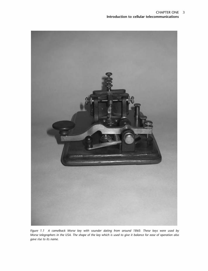
Figure 1.1 A camelback Morse key with sounder dating from around 1860. These keys were used by
Morse telegraphers in the USA. The shape of the key which is used to give it balance for ease of operation also
gave rise to its name.
CHAPTER ONEIntroduction to cellular telecommunications
3
equations, although a number of other people before him had undoubtedly seen effects of
radio waves.
Initially Hertzian waves (as they were first known) were seen as little more than a scientific
novelty. However, a young Italian named Marconi did much to exploit them and apply them to
practical uses for communication. Seeing their potential for enabling communication between
ships, he first approached the Italian navy; when he was turned down, he came to Britain with
his mother (who was of Irish stock) and started to develop his ideas here. He successfully
demonstrated communications over increasing distances, finally, in 1901, transmitting a signal
across the Atlantic.
Marconi concentrated on the marine market, as did many others. Here, wireless was the only
means of communication over long distances, and it was especially valuable in sending distress
messages. A station was set up in the South Goodwin Lightship, not far from Dover in the UK, and
a link between the lightship and the South Foreland lighthouse enabled a number of emergencies
to be reported – including one where a ship named the S.S. R.F. Matthews collided with the
lightship.
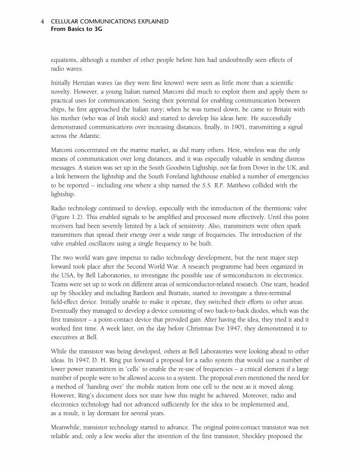
Radio technology continued to develop, especially with the introduction of the thermionic valve
(Figure 1.2). This enabled signals to be amplified and processed more effectively. Until this point
receivers had been severely limited by a lack of sensitivity. Also, transmitters were often spark
transmitters that spread their energy over a wide range of frequencies. The introduction of the
valve enabled oscillators using a single frequency to be built.
The two world wars gave impetus to radio technology development, but the next major step
forward took place after the Second World War. A research programme had been organized in
the USA, by Bell Laboratories, to investigate the possible use of semiconductors in electronics.
Teams were set up to work on different areas of semiconductor-related research. One team, headed
up by Shockley and including Bardeen and Brattain, started to investigate a three-terminal
field-effect device. Initially unable to make it operate, they switched their efforts to other areas.
Eventually they managed to develop a device consisting of two back-to-back diodes, which was the
first transistor – a point-contact device that provided gain. After having the idea, they tried it and it
worked first time. A week later, on the day before Christmas Eve 1947, they demonstrated it to
executives at Bell.
While the transistor was being developed, others at Bell Laboratories were looking ahead to other
ideas. In 1947, D. H. Ring put forward a proposal for a radio system that would use a number of
lower power transmitters in ‘cells’ to enable the re-use of frequencies – a critical element if a large
number of people were to be allowed access to a system. The proposal even mentioned the need for
a method of ‘handing over’ the mobile station from one cell to the next as it moved along.
However, Ring’s document does not state how this might be achieved. Moreover, radio and
electronics technology had not advanced sufficiently for the idea to be implemented and,
as a result, it lay dormant for several years.
Meanwhile, transistor technology started to advance. The original point-contact transistor was not
reliable and, only a few weeks after the invention of the first transistor, Shockley proposed the
CELLULAR COMMUNICATIONS EXPLAINEDFrom Basics to 3G
4
junction transistor. With further developments in semiconductor technology, improved
methods of processing the materials and of manufacturing were developed. As a result,
transistors became cheaper to produce, their performance improved and they became more
reliable, leading to an increase in their use. The field-effect transistor that Bardeen, Brattain
and Shockley had tried to develop also came to fruition, and was to play an important part
in one of the next major developments – that of the integrated circuit.
There had been a number of projects set up to investigate how electronic circuits could be
made smaller and more reliable. However, the development of the integrated circuit has been
attributed to two individuals. The first was Jack Kilby, then a young engineer working for Texas
Instruments. Having insufficient leave, he had to work during the company shutdown. As there was
little call on his time from others, and all the equipment he needed was available, he started
work on developing a small oscillator on a single chip of silicon. Working on his own, he made the
first circuits work successfully on 12 September 1958. The second, Robert Noyce, working for
Fairchild, reasoned that it was nonsensical to make a large number of individual transistors on
a wafer, cut them up to make separate transistors and then reassemble them when equipment
was constructed. Noyce applied this concept, and set down many of the foundations on which
today’s integrated circuit industry is founded.
With many of the enabling technologies in place, the scene was set for mobile phone technology
to start to become a reality. There had been a number of intermediate steps along the way.
Figure 1.2 An example of an early thermionic valve. This ‘R’ valve dates from shortly after the First World War.
CHAPTER ONEIntroduction to cellular telecommunications
5
Mobile radio was already in use. The first walkie-talkies had been made in the USA by Motorola
in 1940, and were still very heavy (35 lb, or about 16 kg), but they enabled the military to
have radio communications on the move. After the war, mobile car telephones were introduced –
the first from AT&T in St Louis, Missouri, USA, in 1946. The service was very successful, and
soon spread to twenty-four other cities. However, these telephones were effectively two-way
radios linked to the ordinary phone network. The services used a transmitter–receiver station
located in the centre of the relevant city and, accordingly, had limited range. Also, owing to the
limited number of frequencies available, there was a waiting list many times longer than the
number of people who were connected. Services were also set up in other countries around
the world, with the same problems of waiting lists longer than the number of users.
Seeing the popularity of these services, and realizing their potential, the idea of a cellular system
like that previously suggested by Ring resurfaced. AT&T lobbied the FCC (Federal Communications
System) in the USA repeatedly between 1958 and 1968, and finally the FCC agreed to set aside
some frequencies for an experimental system. As a result, a radio telephone system employing
frequency re-use was set up aboard a train in 1969. A total of six channels in several zones were
used along the route, which spanned over 200 miles, with the system under computer control.
Meanwhile, in the late 1960s and early 1970s a number of countries started to consider seriously
the possibility of a cellular telecommunications system. In Japan, for example, the Nippon
Telegraph and Telephone Company proposed a nationwide cellular system at 800MHz. Ideas also
started to move forward in Finland. Then, in December 1970, in the USA, the Bell Telephone
Laboratories submitted a patent proposal.
It took until 1975 before the FCC gave approval for Bell to start a trial system, and two more
years before it was allowed to operate. Not surprisingly, the development of a new technology cost
a very significant amount; many millions of dollars were spent, and eventually systems started to be
seen. In fact, the first commercial development cellular telephone system began operation in
May 1978 in Bahrain. Although relatively simple in some respects, the system had two cells and
about 250 subscribers. However, development in the USA moved ahead very swiftly, and
two months later, in July 1978, the Advanced Mobile Phone Service (AMPS) commenced operation
around Chicago. Initially the system was trialled using Bell employees, but in December of that year
paying customers started to use the system. It took until 1983 before full commercialization of
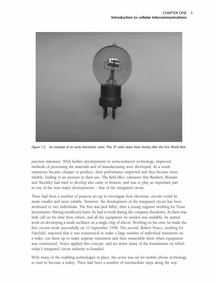
the system took place in the USA; however, the first mobile phone system to be launched
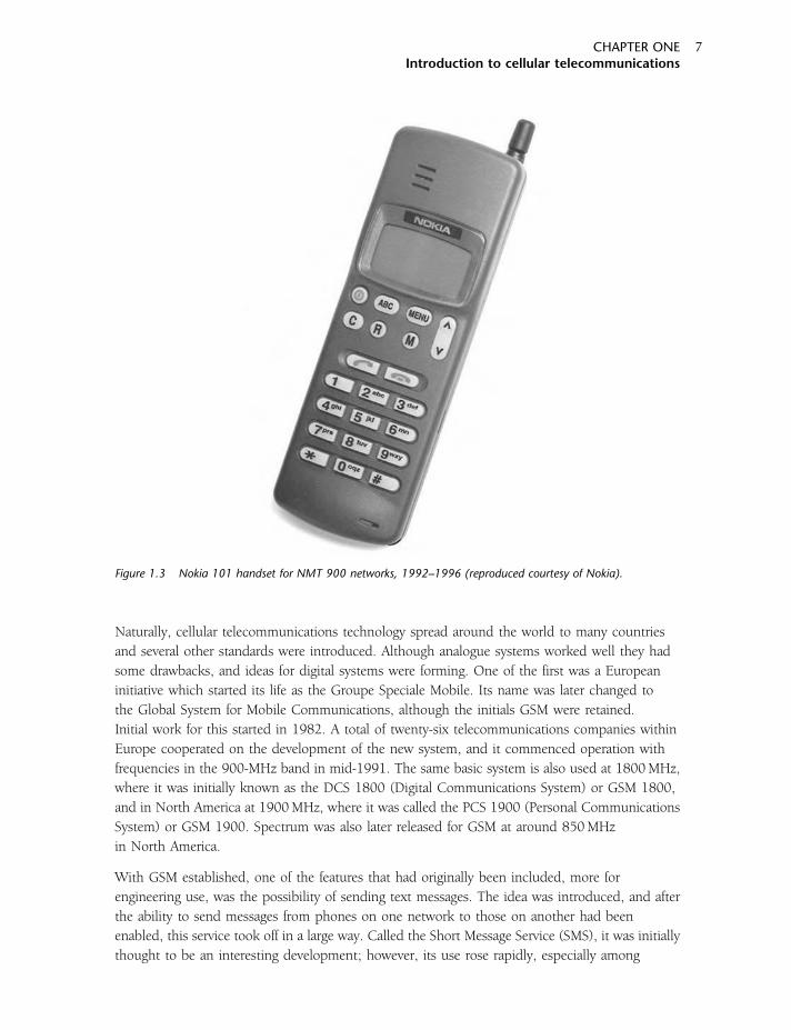
commercially was the Nordic Mobile Telephone (NMT), which was launched in 1979 using a band
of frequencies at 450MHz. This was the result of cooperation between engineers and different
companies across Scandinavia. Figure 1.3 shows a 1992–1996 Nokia 101 handset for
NMT 900 networks.
Development in many parts of Europe followed on behind the USA. A system known as Total
Access Communications System (TACS), developed by Motorola, was used in many countries.
In the UK, licences were awarded in 1985. Two companies were given licences; one company
was partly owned by the previously state-owned British Telecommunications (BT), and the other
was called Racal Vodaphone. Owned by Racal Electronics plc, this company was later floated as
a separate company to become Vodafone, now one of the world’s largest mobile phone companies.
CELLULAR COMMUNICATIONS EXPLAINEDFrom Basics to 3G
6
Naturally, cellular telecommunications technology spread around the world to many countries
and several other standards were introduced. Although analogue systems worked well they had
some drawbacks, and ideas for digital systems were forming. One of the first was a European
initiative which started its life as the Groupe Speciale Mobile. Its name was later changed to
the Global System for Mobile Communications, although the initials GSM were retained.
Initial work for this started in 1982. A total of twenty-six telecommunications companies within
Europe cooperated on the development of the new system, and it commenced operation with
frequencies in the 900-MHz band in mid-1991. The same basic system is also used at 1800MHz,
where it was initially known as the DCS 1800 (Digital Communications System) or GSM 1800,
and in North America at 1900MHz, where it was called the PCS 1900 (Personal Communications
System) or GSM 1900. Spectrum was also later released for GSM at around 850MHz
in North America.
With GSM established, one of the features that had originally been included, more for
engineering use, was the possibility of sending text messages. The idea was introduced, and after
the ability to send messages from phones on one network to those on another had been
enabled, this service took off in a large way. Called the Short Message Service (SMS), it was initially
thought to be an interesting development; however, its use rose rapidly, especially among
Figure 1.3 Nokia 101 handset for NMT 900 networks, 1992–1996 (reproduced courtesy of Nokia).
CHAPTER ONEIntroduction to cellular telecommunications
7
young people who found it a cheap way of communicating using their phones. In 2004,
over 45 billion messages were sent each month. February 2004 also saw the one-billionth
GSM subscriber connected.
In North America, an equivalent system to GSM was introduced. Again, its aim was to be able
to make more efficient use of the available spectrum. In outlying areas, especially, there was not
the same pressure on the spectrum as in many of the cities; accordingly most users were very
satisfied with their analogue systems and the take-up was less than in Europe. Nevertheless,
the North America TDMA system, which operated on a 30-kHz channel spacing, was rolled out
in many areas. A very similar system was also used in Japan, where it was known as Pacific or
Personal Digital Cellular (PDC).
Meanwhile, in the USA, a company named Qualcomm proposed a system based on a spread
spectrum technique, previously used mainly for military covert activities. The first issue of the
specification, IS-95, was available in draft format in 1993, with September 1995 seeing the first
deployment of the system, by Hutchison Telecom in Hong Kong, followed shortly afterwards
by SK Telecom in South Korea. The system was given the trade name cdmaOneTM, and soon
started to spread in both the USA and Asia Pacific regions.
As the 1990s came to a close, the cellular phone industry was booming. Industry analysts reasoned
that people would want to use far more data services as they saw a significant rise in the use of the
Internet. Existing systems were not able to support sufficiently fast data services, and new systems
were sought. The first step on the way was known as the General Packet Radio System (GPRS), and
its enhanced system as Enhanced Data rates for Global Evolution (EDGE). These systems were
dubbed 2.5G, as they were a development of the second-generation system. Similar requirements
were also placed on cdmaOne. Although it was able to provide low data rates, its specification
was upgraded to support more data activity.
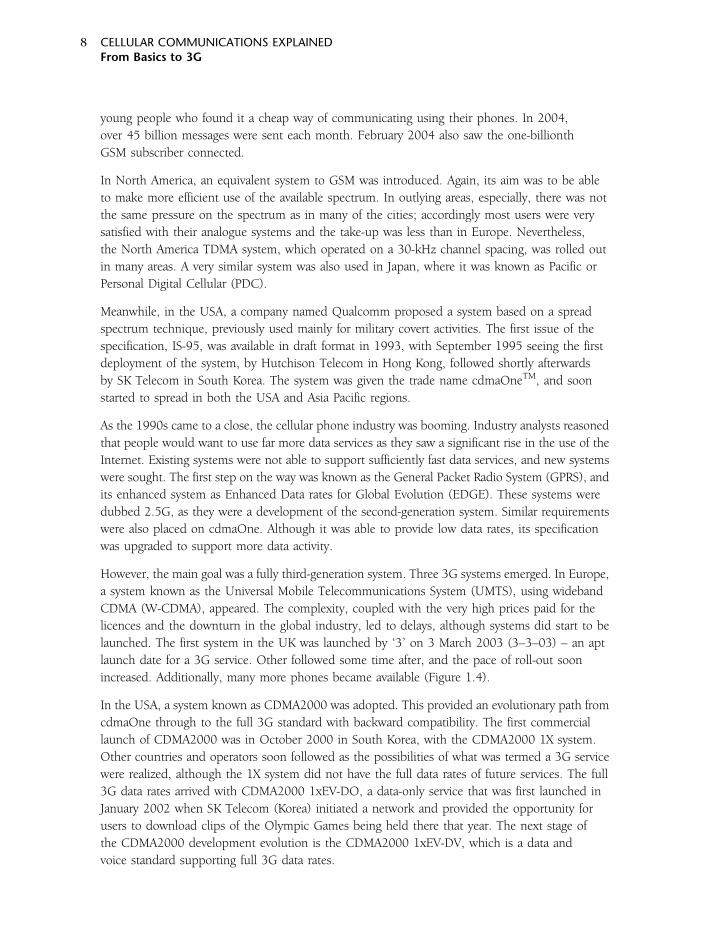
However, the main goal was a fully third-generation system. Three 3G systems emerged. In Europe,
a system known as the Universal Mobile Telecommunications System (UMTS), using wideband
CDMA (W-CDMA), appeared. The complexity, coupled with the very high prices paid for the
licences and the downturn in the global industry, led to delays, although systems did start to be
launched. The first system in the UK was launched by ‘3’ on 3 March 2003 (3–3–03) – an apt
launch date for a 3G service. Other followed some time after, and the pace of roll-out soon
increased. Additionally, many more phones became available (Figure 1.4).
In the USA, a system known as CDMA2000 was adopted. This provided an evolutionary path from
cdmaOne through to the full 3G standard with backward compatibility. The first commercial
launch of CDMA2000 was in October 2000 in South Korea, with the CDMA2000 1X system.
Other countries and operators soon followed as the possibilities of what was termed a 3G service
were realized, although the 1X system did not have the full data rates of future services. The full
3G data rates arrived with CDMA2000 1xEV-DO, a data-only service that was first launched in
January 2002 when SK Telecom (Korea) initiated a network and provided the opportunity for
users to download clips of the Olympic Games being held there that year. The next stage of
the CDMA2000 development evolution is the CDMA2000 1xEV-DV, which is a data and
voice standard supporting full 3G data rates.
CELLULAR COMMUNICATIONS EXPLAINEDFrom Basics to 3G
8
A third system, known as Time Division Synchronous CDMA (TD-SCDMA), was developed in
China. Although the Chinese rolled out both UMTS and CDMA2000, they were keen also to
have a system developed in China. Using a TDD approach, where the transmission and
reception were undertaken on the same channel but split in time, this approach has a number
of advantages to offer under some circumstances. However, its development is somewhat
behind that of UMTS and CDMA2000, and it will not be addressed in the later chapters.
Overview of the systems
Since the introduction of the first cellular telecommunications networks, many different
standards or systems have been used, all with their own abbreviations. They also have different
specifications, such as channel spacing and access technology (i.e. the means for supporting
a large number of users), and they offer different levels of capability. Before progressing to the
way in which cellular phones work, and the details of the different major systems, it is worth
taking time to overview the different major systems that are (or have been) in use around the globe.
As already mentioned, there are the three generations of system, generally known as 1G, 2G and
3G to denote the different generations. The first-generation systems were characterized by the fact
Figure 1.4 The Nokia 770 Internet tablet (reproduced courtesy of Nokia).
CHAPTER ONEIntroduction to cellular telecommunications
9
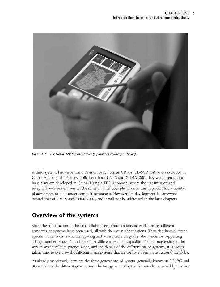
Table 1.1 Summary of the major cellular telecommunications systems and their capabilities.
System Generation Channel spacing Access Comments
AMPS 1G 30 kHz FDMA Advanced Mobile Phone System; this analogue system was first developed and
used in the USA.
NAMPS 1G 10 kHz FDMA Narrow band version of AMPS, chiefly used in the USA and Israel, based on
a 10-kHz channel spacing.
TACS 1G 25 kHz FDMA An analogue system used originally in the UK and based around 900MHz, this
system spread worldwide. After the system was first introduced, further channels
were allocated to reduce congestion, in a standard known as Extended TACS
(or ETACS).
NMT 1G 25 kHz FDMA Nordic Mobile Telephone. This analogue system was the first system to be widely
used commercially. Initially based on 450MHz and later at 900MHz, it was used
chiefly in Scandinavia but was adopted by up to thirty other countries.
NTT 1G 25 kHz FDMA An analogue system used in Japan, operating at frequencies in the region of
900MHz.
C450 1G 20 kHz FDMA System used in Germany, operating in the region of 450MHz.
GSM 2G 200 kHz TDMA Originally called Groupe Speciale Mobile, the initials later stood for Global System
for Mobile communications. It was developed in Europe and first introduced in
1991. The service is normally based around 900MHz, although some 850-MHz
allocations exist in the USA.
DCS 1800 2G 200 kHz TDMA 1800-MHz derivation of GSM, this is also known as GSM 1800.
PCS 1900 2G 200 kHz TDMA 1900-MHz derivation of GSM, this is also known as GSM 1900.
US-TDMA 2G 30 kHz TDMA This system, sometimes called North America Digital Cellular or US Digital Cellular,
was introduced in 1991 and is also known by its standard number (IS-54), which
was later updated to standard IS-136. As it is based on a TDMA system, it is
normally referred to as US-TDMA or just TDMA in the countries where it is used. It
is a 2G digital system that was designed to operate alongside the AMPS system.
PDC 2G 30 kHz TDMA Pacific Digital Cellular. A system similar to NA-TDMA, but used only in Japan.
GPRS 2.5G 200 kHz TDMA General Packet Radio Service. A data service that can be layered onto GSM. It uses
packet switching instead of circuit switching to provide the required perfor-
mance, and data rates of up to 115 kbps are attainable.
10

EDGE 2.5/3G 200 kHz TDMA Enhanced Data rates for GSM Evolution. The system uses a different form of
modulation (8PSK) and packet switching, which is overlaid on top of GSM to
provide the enhanced performance. Systems using the EDGE system may also
be known as EGPRS systems.
cdmaOne 2G 1.25MHz CDMA This is the brand name for the system with the standard reference IS-95, which was
the first CDMA system to gain widespread use. The initial specification for the
system was IS-95A, but its performance was later upgraded under IS-95B. Apart
from voice, it also carries data at rates up to 14.4 kbps for IS-95A; under IS-95B,
data rates of up to 115 kbps are supported.
CDMA2000 1X 2.5G 1.25MHz CDMA This system supports both voice and data capabilities within a standard 1.25-MHz
CDMA channel. CDMA2000 builds on cdmaOne to provide an evolution path to
3G. The system doubles the voice capacity of cdmaOne systems, and also
supports high-speed data services. Peak data rates of 153 kbps are currently
achievable, with figures of 307 kbps quoted for the future, and 614 kbps when
two channels are used.
CDMA2000 1xEV-DO 3G 1.25MHz CDMA The EV-DO stands for Evolution Data Only. This is an evolution of CDMA 2000 that
is designed for data-only use, and its specification is IS-856. It provides a peak
data-rate capability of over 2.45Mbps on the forward or downlink – i.e. from the
base station to the user. The aim of the system is to deliver a low cost per
megabyte capability along with an always-on connection costed on the data
downloaded rather than connection time.
CDMA2000 1xEV-DV 3G 1.25MHz CDMA This stands for Evolution Data and Voice. It is an evolution of CDMA2000 that can
simultaneously transmit voice and data. The peak data rate is 3.1Mbps on the
forward link; the reverse link is very similar to that of CDMA2000 1X and is limited
to 384 kbps.
UMTS 3G 5MHz CDMA/TDMA The Universal Mobile Telecommunications System uses Wideband CDMA
(W-CDMA) with one 5-MHz channel for both voice and data, providing data
speeds of up to 2Mbps.
TD-SCDMA 3G 1.6MHz CDMA Time Division Synchronous CDMA. A system developed in China to establish their
position on the cellular telecommunications arena, it uses the same bands for
transmit and receive, allowing different time slots for base stations and mobiles to
communicate. Unlike other 3G systems, it uses a time division duplex (TDD)
system.
11
that they were based on analogue technology. They separated different users in the same cell by
allocating them different channels. This technique is known as Frequency Division Multiple Access
(FDMA).
As demand grew, the available spectrum became progressively more congested. As a result,
it quickly became obvious that less spectrum-hungry techniques would be required. As a result, the
second-generation (or 2G) systems were born. These employed digital technology to provide the
required levels of efficiency. The two early second-generation systems, namely GSM and US-TDMA,
as well as its derivative PDC, all used a combination of FDMA and another technique whereby
different users were allocated different timeslots on the same channel. This system is known as
Time Division Multiple Access (TDMA). These systems offered limited data facilities. However,
with revenues from voice traffic levelling off and operators seeing the opportunities for increased
business as a result of data traffic, a move towards systems that could provide the performance
required to make this viable was taken.
Before these high data-rate systems could be introduced to provide the high-speed data third
generation or 3G systems, interim solutions were sought. These so called 2.5G systems provided
higher data rates than were possible with the existing 2G systems. A system known as the General
Packet Radio Service (GPRS) used with GSM provided an increase in data rate. Here, the chief
change was to use a packet radio system, where individual packets of data are routed to the user,
rather than using circuit-switched data, where a circuit is allocated 100 per cent to a given user.
Using a packet-switched approach enables the dead periods in another call to be used productively
by a user, thereby improving the efficiency of the overall system. A further data-rate improvement
has been provided by another system, known as Enhanced Data rates for GSM Evolution (EDGE).
Here, a different form of modulation is used to provide the data-rate increase.
Although GSM, US-TDMA and PDC use a time-division approach, another system used a different
approach. Based on a spread spectrum technology, it used different codes to provide access to
different users. Known as Code Division Multiple Access (CDMA), this technology was originally
used on a system known as cdmaOne. This system was a 2G technology, but was upgraded
through several evolutionary upgrades to provide a full 3G service.
The major cellular telecommunications systems and their capabilities are summarized in Table 1.1.
CELLULAR COMMUNICATIONS EXPLAINEDFrom Basics to 3G
12
2CHAPTER TWO
Radio waves and propagation
The nature of radio signals and the way in which they travel are a key elements in cellular systems.
The frequencies that are used are chosen as a result of many factors, some of which are technical
and others resulting from spectrum allocation issues. Nevertheless, technical issues play a key role
in determining many features associated with the cellular networks and are thus of great
importance. The nature of the signals, the way they travel and how they are influenced by
their surroundings play a major part in determining how a network is planned.
Radio waves are a form of radiation known as electromagnetic waves. As they contain both electric
and magnetic elements, it is necessary to take a look at these fields before looking at the
electromagnetic wave itself.
Electric fields
Any electrically charged object, whether it has a static charge or is carrying a current, has an electric
field associated with it. It is a commonly known fact that like charges repel one another and
opposite charges attract. This can be demonstrated in a number of ways. For example, hair often
tends to stand up after it has been brushed or combed. The brushing action generates an
electrostatic charge on the hairs and, as they all have the same type of charge, they tend to repel one
another and stand up. In this way it can be seen that a force is exerted between them. Examples like
this are quite dramatic, and result because the voltages that are involved are very high and can
typically be many kilovolts. However, even the comparatively low voltages that are found
in electronic circuits exhibit the same effects, although to a much smaller degree.
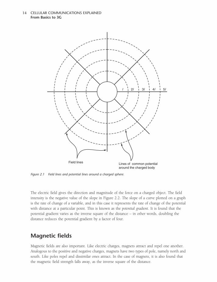
The electric field radiates out from any item with an electric potential, as shown in Figure 2.1.
The electrostatic potential falls away as the distance from the object is increased. Take the example
of a charged sphere with a potential of 10 volts. At the surface of the sphere, the electrostatic
potential is 10 V. However, as the distance from the sphere is increased, this potential starts to fall.
It can be seen that it is possible to draw lines of equal potential around the sphere.
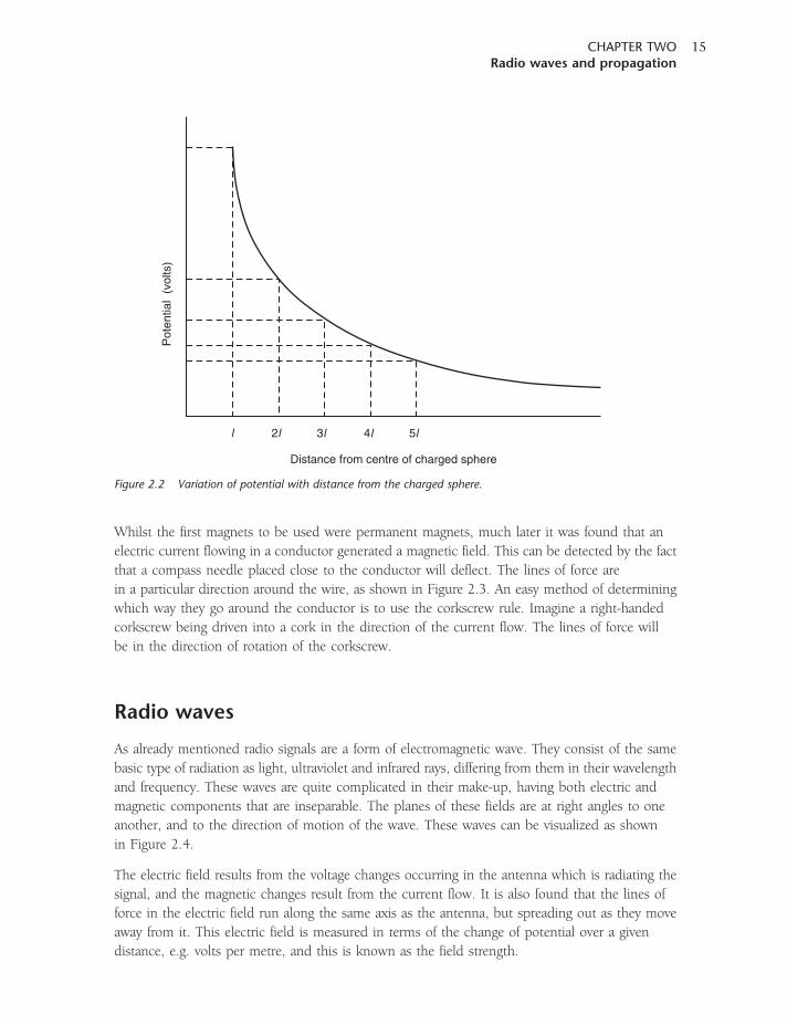
The potential falls away as the distance is increased from the sphere, and it can be shown that
this occurs as the inverse of the distance – that is, doubling the distance halves the potential.
The variation of potential with the distance from the sphere is shown in Figure 2.2.
The electric field gives the direction and magnitude of the force on a charged object. The field
intensity is the negative value of the slope in Figure 2.2. The slope of a curve plotted on a graph
is the rate of change of a variable, and in this case it represents the rate of change of the potential
with distance at a particular point. This is known as the potential gradient. It is found that the
potential gradient varies as the inverse square of the distance – in other words, doubling the
distance reduces the potential gradient by a factor of four.
Magnetic fields
Magnetic fields are also important. Like electric charges, magnets attract and repel one another.
Analogous to the positive and negative charges, magnets have two types of pole, namely north and
south. Like poles repel and dissimilar ones attract. In the case of magnets, it is also found that
the magnetic field strength falls away, as the inverse square of the distance.
l 2l 3l 4l 5l
Field lines Lines of common potentialaround the charged body
Figure 2.1 Field lines and potential lines around a charged sphere.
CELLULAR COMMUNICATIONS EXPLAINEDFrom Basics to 3G
14
Whilst the first magnets to be used were permanent magnets, much later it was found that an
electric current flowing in a conductor generated a magnetic field. This can be detected by the fact
that a compass needle placed close to the conductor will deflect. The lines of force are
in a particular direction around the wire, as shown in Figure 2.3. An easy method of determining
which way they go around the conductor is to use the corkscrew rule. Imagine a right-handed
corkscrew being driven into a cork in the direction of the current flow. The lines of force will
be in the direction of rotation of the corkscrew.
Radio waves
As already mentioned radio signals are a form of electromagnetic wave. They consist of the same
basic type of radiation as light, ultraviolet and infrared rays, differing from them in their wavelength
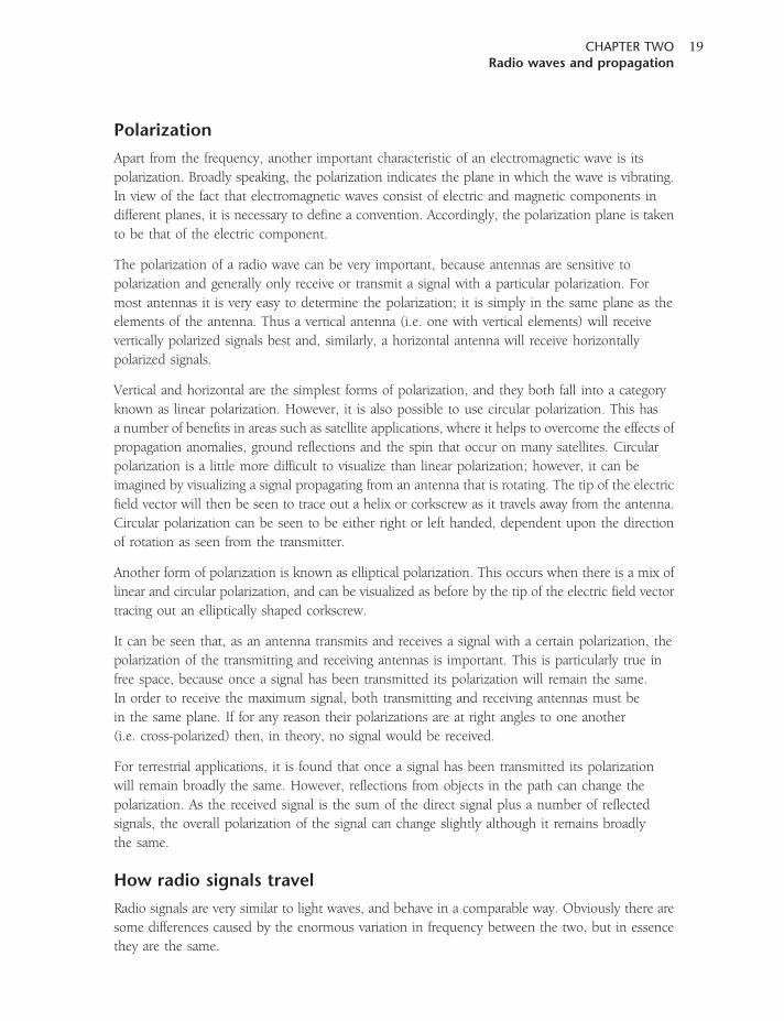
and frequency. These waves are quite complicated in their make-up, having both electric and
magnetic components that are inseparable. The planes of these fields are at right angles to one
another, and to the direction of motion of the wave. These waves can be visualized as shown
in Figure 2.4.
The electric field results from the voltage changes occurring in the antenna which is radiating the
signal, and the magnetic changes result from the current flow. It is also found that the lines of
force in the electric field run along the same axis as the antenna, but spreading out as they move
away from it. This electric field is measured in terms of the change of potential over a given
distance, e.g. volts per metre, and this is known as the field strength.
Pot
entia
l (v
olts
)
Distance from centre of charged sphere
l 2l 3l 4l 5l
Figure 2.2 Variation of potential with distance from the charged sphere.
CHAPTER TWORadio waves and propagation
15
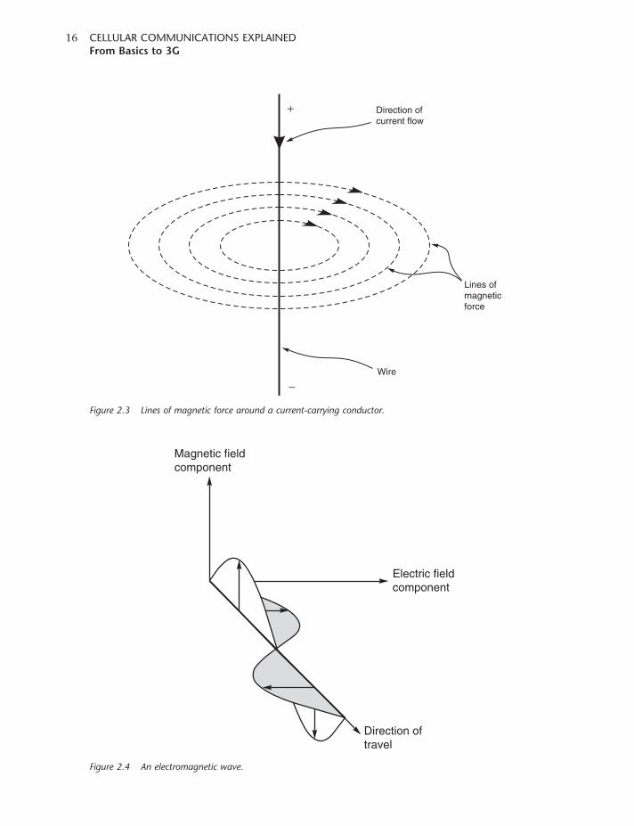
Magnetic fieldcomponent
Electric fieldcomponent
Direction oftravel
Figure 2.4 An electromagnetic wave.
+
Wire
Direction ofcurrent flow
Lines ofmagneticforce
−
Figure 2.3 Lines of magnetic force around a current-carrying conductor.
CELLULAR COMMUNICATIONS EXPLAINEDFrom Basics to 3G
16
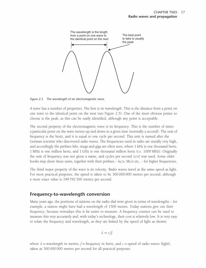
A wave has a number of properties. The first is its wavelength. This is the distance from a point on
one wave to the identical point on the next (see Figure 2.5). One of the most obvious points to
choose is the peak, as this can be easily identified, although any point is acceptable.
The second property of the electromagnetic wave is its frequency. This is the number of times
a particular point on the wave moves up and down in a given time (normally a second). The unit of
frequency is the hertz, and it is equal to one cycle per second. This unit is named after the
German scientist who discovered radio waves. The frequencies used in radio are usually very high,
and accordingly the prefixes kilo, mega and giga are often seen, where 1 kHz is one thousand hertz,
1MHz is one million hertz, and 1GHz is one thousand million hertz (i.e. 1000MHz). Originally
the unit of frequency was not given a name, and cycles per second (c/s) was used. Some older
books may show these units, together with their prefixes – kc/s; Mc/s etc. – for higher frequencies.
The third major property of the wave is its velocity. Radio waves travel at the same speed as light.
For most practical purposes, the speed is taken to be 300 000 000 metres per second, although
a more exact value is 299 792 500 metres per second.
Frequency-to-wavelength conversion
Many years ago, the positions of stations on the radio dial were given in terms of wavelengths – for
example, a station might have had a wavelength of 1500 metres. Today stations give out their
frequency, because nowadays this is far easier to measure. A frequency counter can be used to
measure this very accurately and, with today’s technology, their cost is relatively low. It is very easy
to relate the frequency and wavelength, as they are linked by the speed of light as shown:
l ¼ c=f
where l¼wavelength in metres, f¼ frequency in hertz, and c¼ speed of radio waves (light),
taken as 300 000 000 metres per second for all practical purposes.
The wavelength is the lengthfrom a point on one wave tothe identical point on the next
The best pointto take is usuallythe peak
Figure 2.5 The wavelength of an electromagnetic wave.
CHAPTER TWORadio waves and propagation
17
Taking the previous example, the wavelength of 1500 metres corresponds to a frequency of
300 000 000/1500, or 200 000 hertz (200 kHz).
Radio spectrum
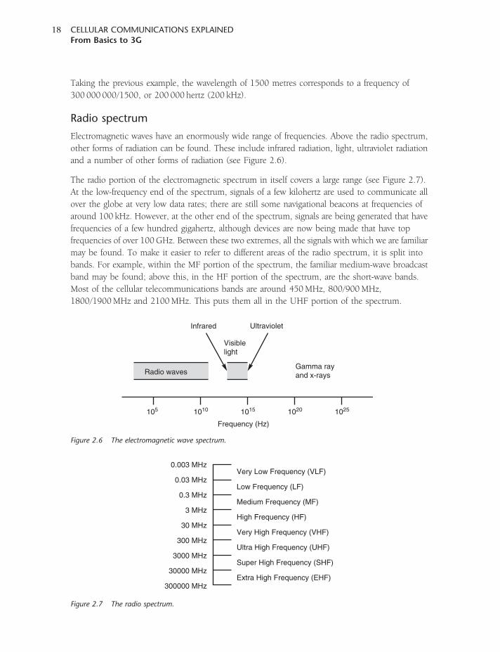
Electromagnetic waves have an enormously wide range of frequencies. Above the radio spectrum,
other forms of radiation can be found. These include infrared radiation, light, ultraviolet radiation
and a number of other forms of radiation (see Figure 2.6).
The radio portion of the electromagnetic spectrum in itself covers a large range (see Figure 2.7).
At the low-frequency end of the spectrum, signals of a few kilohertz are used to communicate all
over the globe at very low data rates; there are still some navigational beacons at frequencies of
around 100 kHz. However, at the other end of the spectrum, signals are being generated that have
frequencies of a few hundred gigahertz, although devices are now being made that have top
frequencies of over 100GHz. Between these two extremes, all the signals with which we are familiar
may be found. To make it easier to refer to different areas of the radio spectrum, it is split into
bands. For example, within the MF portion of the spectrum, the familiar medium-wave broadcast
band may be found; above this, in the HF portion of the spectrum, are the short-wave bands.
Most of the cellular telecommunications bands are around 450MHz, 800/900MHz,
1800/1900MHz and 2100MHz. This puts them all in the UHF portion of the spectrum.
Very Low Frequency (VLF)
Low Frequency (LF)
Medium Frequency (MF)
High Frequency (HF)
Very High Frequency (VHF)
Ultra High Frequency (UHF)
Super High Frequency (SHF)
Extra High Frequency (EHF)
0.003 MHz
0.03 MHz
0.3 MHz
3 MHz
30 MHz
300 MHz
3000 MHz
30000 MHz
300000 MHz
Figure 2.7 The radio spectrum.
105 1010 1015 1020 1025
Radio waves
Visiblelight
Infrared Ultraviolet
Gamma rayand x-rays
Frequency (Hz)
Figure 2.6 The electromagnetic wave spectrum.
CELLULAR COMMUNICATIONS EXPLAINEDFrom Basics to 3G
18
Polarization
Apart from the frequency, another important characteristic of an electromagnetic wave is its
polarization. Broadly speaking, the polarization indicates the plane in which the wave is vibrating.
In view of the fact that electromagnetic waves consist of electric and magnetic components in
different planes, it is necessary to define a convention. Accordingly, the polarization plane is taken
to be that of the electric component.
The polarization of a radio wave can be very important, because antennas are sensitive to
polarization and generally only receive or transmit a signal with a particular polarization. For
most antennas it is very easy to determine the polarization; it is simply in the same plane as the
elements of the antenna. Thus a vertical antenna (i.e. one with vertical elements) will receive
vertically polarized signals best and, similarly, a horizontal antenna will receive horizontally
polarized signals.
Vertical and horizontal are the simplest forms of polarization, and they both fall into a category
known as linear polarization. However, it is also possible to use circular polarization. This has
a number of benefits in areas such as satellite applications, where it helps to overcome the effects of
propagation anomalies, ground reflections and the spin that occur on many satellites. Circular
polarization is a little more difficult to visualize than linear polarization; however, it can be
imagined by visualizing a signal propagating from an antenna that is rotating. The tip of the electric
field vector will then be seen to trace out a helix or corkscrew as it travels away from the antenna.
Circular polarization can be seen to be either right or left handed, dependent upon the direction
of rotation as seen from the transmitter.
Another form of polarization is known as elliptical polarization. This occurs when there is a mix of
linear and circular polarization, and can be visualized as before by the tip of the electric field vector
tracing out an elliptically shaped corkscrew.
It can be seen that, as an antenna transmits and receives a signal with a certain polarization, the
polarization of the transmitting and receiving antennas is important. This is particularly true in
free space, because once a signal has been transmitted its polarization will remain the same.
In order to receive the maximum signal, both transmitting and receiving antennas must be
in the same plane. If for any reason their polarizations are at right angles to one another
(i.e. cross-polarized) then, in theory, no signal would be received.
For terrestrial applications, it is found that once a signal has been transmitted its polarization
will remain broadly the same. However, reflections from objects in the path can change the
polarization. As the received signal is the sum of the direct signal plus a number of reflected
signals, the overall polarization of the signal can change slightly although it remains broadly
the same.
How radio signals travel
Radio signals are very similar to light waves, and behave in a comparable way. Obviously there are
some differences caused by the enormous variation in frequency between the two, but in essence
they are the same.
CHAPTER TWORadio waves and propagation
19
A signal may be radiated or transmitted at a certain point, and the radio waves travel
outwards – much like the waves seen on a pond if a stone is dropped into it. As they move
outwards they become weaker, as they have to cover a much wider area. However, they can
still travel over enormous distances – light can be seen from stars many light years away.
Radio waves can travel over similar distances. As distant galaxies and quasars emit radio signals
these can be detected by radio telescopes, which can pick up the minute signals and then analyse
them to give us further clues about what exists in the outer extremities of the universe.
While the waves on a pond become weaker as they move further outwards, the same is true of radio
waves because the area on a sphere they have to cover is much greater. From simple geometry,
it can be deduced that the area of the surface is proportional to the radius squared. Accordingly,
the signal strength is inversely proportional to the square of the distance from the source to the
receiver. This may be expressed mathematically: strength is proportional to 1/d2, where d is the
distance from the transmitter.
These calculations are true for what is termed ‘free space propagation’ – that is, when the signal
travels in free space and is not affected by any other objects or areas that may affect the propagation
of the signal. A typical terrestrial environment is very different to this, as trees, vegetation, buildings
and many other obstacles line the path of the signal, and it is found that the signal dies away
at a much faster rate. Often it is closer to a rate proportional to 1/d4, and typically a figure of this
order will be used when planning a cellular network. Some cell-phone network planners may use
a factor of 1/d3.8. Whatever the exact figure used it can be seen that ranges achievable are relatively
small, and therefore in order to obtain sufficient coverage for a network a large number of
cell-phone masts are required.
Refraction, reflection and diffraction
With many obstacles in the path of a typical cell-phone signal travelling between a mobile phone
and the base station (or vice versa), reflection and diffraction are important elements in
understanding the signal path. Refraction may also be encountered, under some circumstances,
on long paths.
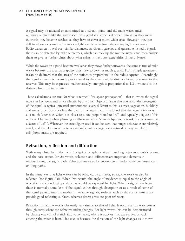
In the same way that light waves can be reflected by a mirror, so radio waves can also be
reflected (see Figure 2.8). When this occurs, the angle of incidence is equal to the angle of
reflection for a conducting surface, as would be expected for light. When a signal is reflected
there is normally some loss of the signal, either through absorption or as a result of some of
the signal passing into the medium. For radio signals, surfaces such as the sea or most areas
provide good reflecting surfaces, whereas desert areas are poor reflectors.
Refraction of radio waves is obviously very similar to that of light. It occurs as the wave passes
through areas where the refractive index changes. For light waves this can be demonstrated
by placing one end of a stick into some water, where it appears that the section of stick
entering the water is bent. This occurs because the direction of the light changes as it moves
CELLULAR COMMUNICATIONS EXPLAINEDFrom Basics to 3G
20
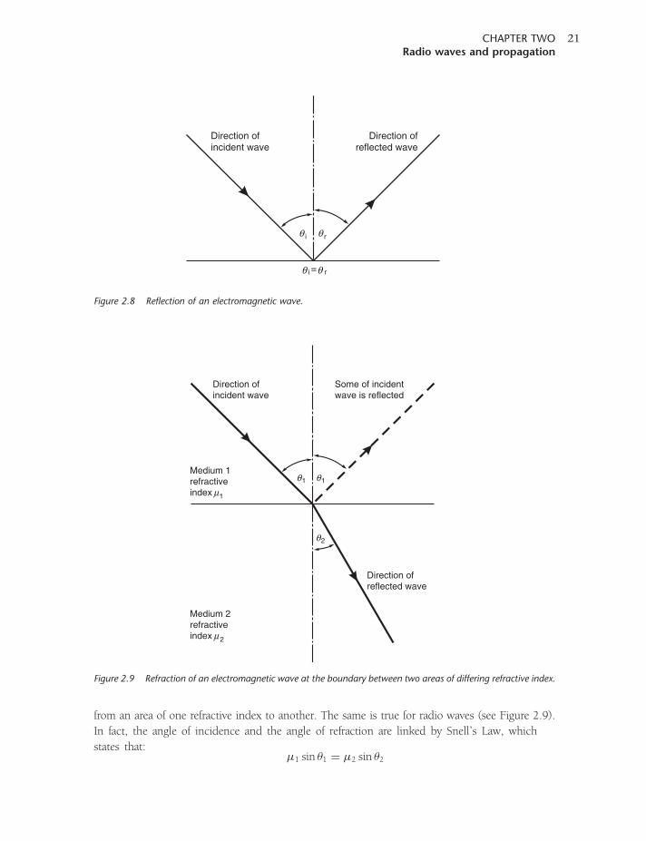
from an area of one refractive index to another. The same is true for radio waves (see Figure 2.9).
In fact, the angle of incidence and the angle of refraction are linked by Snell’s Law, which
states that:�1 sin �1 ¼ �2 sin �2
Direction ofincident wave
Some of incidentwave is reflected
Medium 1refractiveindex 1µ
Direction ofreflected wave
1θ 1θ
2θ
Medium 2refractiveindex 2µ
Figure 2.9 Refraction of an electromagnetic wave at the boundary between two areas of differing refractive index.
Direction ofincident wave
Direction ofreflected wave
iθ rθ
i = rθθ
Figure 2.8 Reflection of an electromagnetic wave.
CHAPTER TWORadio waves and propagation
21
In many cases where radio waves are travelling through the atmosphere there is a gradual change
in the refractive index of the medium. This causes a steady bending of the wave rather than
an immediate change in direction.
It is found that the refractive index of the areas above the Earth’s surface changes slightly, with the
area of higher refractive index normally being closer to the ground. This means that when signals
are not obstructed by buildings and other objects, and travel over longer distances, they may be
refracted by the change in refractive index. Although more pertinent to applications such as
broadcasting, it is found that coverage of a station is extended beyond the line of sight by
approximately one-third. As the refraction occurs in a region of the atmosphere affected by the
weather, it is found that weather conditions also play a part in determining tropospheric radio
propagation conditions. Under some circumstances (for example, when a stable high-pressure area
is present), distances may be extended beyond their normal ranges.
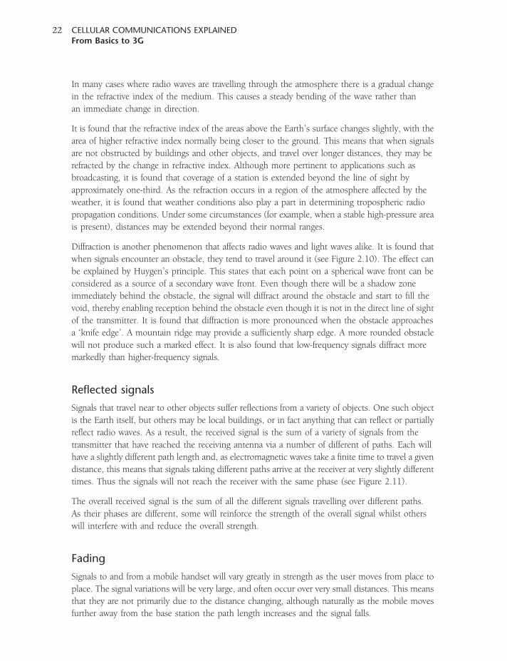
Diffraction is another phenomenon that affects radio waves and light waves alike. It is found that
when signals encounter an obstacle, they tend to travel around it (see Figure 2.10). The effect can
be explained by Huygen’s principle. This states that each point on a spherical wave front can be
considered as a source of a secondary wave front. Even though there will be a shadow zone
immediately behind the obstacle, the signal will diffract around the obstacle and start to fill the
void, thereby enabling reception behind the obstacle even though it is not in the direct line of sight
of the transmitter. It is found that diffraction is more pronounced when the obstacle approaches
a ‘knife edge’. A mountain ridge may provide a sufficiently sharp edge. A more rounded obstacle
will not produce such a marked effect. It is also found that low-frequency signals diffract more
markedly than higher-frequency signals.
Reflected signals
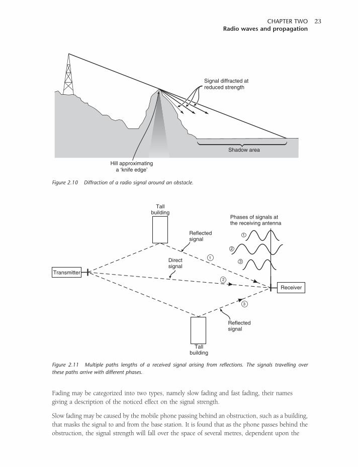
Signals that travel near to other objects suffer reflections from a variety of objects. One such object
is the Earth itself, but others may be local buildings, or in fact anything that can reflect or partially
reflect radio waves. As a result, the received signal is the sum of a variety of signals from the
transmitter that have reached the receiving antenna via a number of different of paths. Each will
have a slightly different path length and, as electromagnetic waves take a finite time to travel a given
distance, this means that signals taking different paths arrive at the receiver at very slightly different
times. Thus the signals will not reach the receiver with the same phase (see Figure 2.11).
The overall received signal is the sum of all the different signals travelling over different paths.
As their phases are different, some will reinforce the strength of the overall signal whilst others
will interfere with and reduce the overall strength.
Fading
Signals to and from a mobile handset will vary greatly in strength as the user moves from place to
place. The signal variations will be very large, and often occur over very small distances. This means
that they are not primarily due to the distance changing, although naturally as the mobile moves
further away from the base station the path length increases and the signal falls.
CELLULAR COMMUNICATIONS EXPLAINEDFrom Basics to 3G
22
Fading may be categorized into two types, namely slow fading and fast fading, their names
giving a description of the noticed effect on the signal strength.
Slow fading may be caused by the mobile phone passing behind an obstruction, such as a building,
that masks the signal to and from the base station. It is found that as the phone passes behind the
obstruction, the signal strength will fall over the space of several metres, dependent upon the
1
2
3
Tallbuilding
Tallbuilding
Transmitter
Receiver
Directsignal
Reflectedsignal
Reflectedsignal
1
2
3
Phases of signals atthe receiving antenna
Figure 2.11 Multiple paths lengths of a received signal arising from reflections. The signals travelling over
these paths arrive with different phases.
Shadow area
Hill approximatinga ‘knife edge’
Signal diffracted atreduced strength
Figure 2.10 Diffraction of a radio signal around an obstacle.
CHAPTER TWORadio waves and propagation
23
nature of the obstruction and distance from it. When the phone is travelling or moving, this gives
a fade that is relatively slow when compared to fast fading, which is explained next.
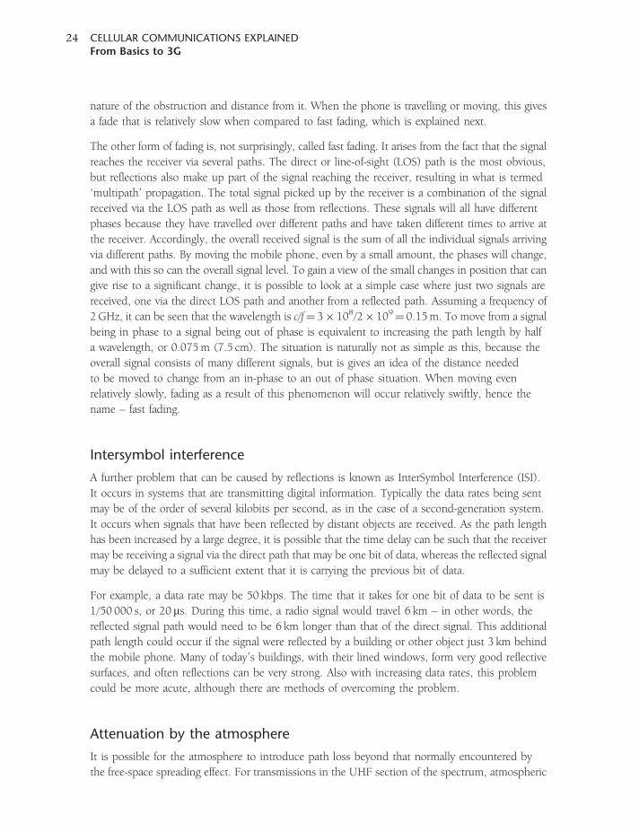
The other form of fading is, not surprisingly, called fast fading. It arises from the fact that the signal
reaches the receiver via several paths. The direct or line-of-sight (LOS) path is the most obvious,
but reflections also make up part of the signal reaching the receiver, resulting in what is termed
‘multipath’ propagation. The total signal picked up by the receiver is a combination of the signal
received via the LOS path as well as those from reflections. These signals will all have different
phases because they have travelled over different paths and have taken different times to arrive at
the receiver. Accordingly, the overall received signal is the sum of all the individual signals arriving
via different paths. By moving the mobile phone, even by a small amount, the phases will change,
and with this so can the overall signal level. To gain a view of the small changes in position that can
give rise to a significant change, it is possible to look at a simple case where just two signals are
received, one via the direct LOS path and another from a reflected path. Assuming a frequency of
2GHz, it can be seen that the wavelength is c/f¼ 3� 108/2� 109¼ 0.15m. To move from a signal
being in phase to a signal being out of phase is equivalent to increasing the path length by half
a wavelength, or 0.075m (7.5 cm). The situation is naturally not as simple as this, because the
overall signal consists of many different signals, but is gives an idea of the distance needed
to be moved to change from an in-phase to an out of phase situation. When moving even
relatively slowly, fading as a result of this phenomenon will occur relatively swiftly, hence the
name – fast fading.
Intersymbol interference
A further problem that can be caused by reflections is known as InterSymbol Interference (ISI).
It occurs in systems that are transmitting digital information. Typically the data rates being sent
may be of the order of several kilobits per second, as in the case of a second-generation system.
It occurs when signals that have been reflected by distant objects are received. As the path length
has been increased by a large degree, it is possible that the time delay can be such that the receiver
may be receiving a signal via the direct path that may be one bit of data, whereas the reflected signal
may be delayed to a sufficient extent that it is carrying the previous bit of data.
For example, a data rate may be 50 kbps. The time that it takes for one bit of data to be sent is
1/50 000 s, or 20 ms. During this time, a radio signal would travel 6 km – in other words, the
reflected signal path would need to be 6 km longer than that of the direct signal. This additional
path length could occur if the signal were reflected by a building or other object just 3 km behind
the mobile phone. Many of today’s buildings, with their lined windows, form very good reflective
surfaces, and often reflections can be very strong. Also with increasing data rates, this problem
could be more acute, although there are methods of overcoming the problem.
Attenuation by the atmosphere
It is possible for the atmosphere to introduce path loss beyond that normally encountered by
the free-space spreading effect. For transmissions in the UHF section of the spectrum, atmospheric
CELLULAR COMMUNICATIONS EXPLAINEDFrom Basics to 3G
24
conditions such as rain and fog have little effect on the signals. However, as the frequency increases
the atmosphere has a much greater effect on the level of attenuation in the signal path, and
at certain frequencies the loss that is introduced has to be considered.
However, as the frequencies rise above about 3GHz the loss can introduce an additional degree of
variation into the path. As may be expected, the loss is dependent upon the amount of rain and
also the size of the droplets. As a rough guide, very heavy rain may introduce an additional loss of
about 1 dB per kilometre at around 5GHz, and more at higher frequencies. The loss occurs for
two reasons. The first is absorption by the rain droplets, with the level of actual attenuation being
dependent upon the droplet size. The second occurs as a result of the signal being scattered,
and although the power is not lost, not all of it travels in the original direction it was intended.
In this way, the antenna gain is effectively reduced.
At frequencies well above 10GHz, attenuation arising from the gases in the air may be evident – in
particular, water vapour and oxygen. This arises by virtue of the permanent electric dipole moment
of the water vapour and the permanent magnetic dipole moment of the oxygen molecule. There are
peaks for the components, with an oxygen peak around 60GHz giving rise to an attenuation of
around 15 dB per kilometre, and a lower peak at just over 100GHz giving rise to attenuation of just
under 2 dB per kilometre. Water vapour losses rise steadily with frequency but peak just below
200GHz, introducing a loss of nearly 40 dB per kilometre. For the current frequencies in use
by cellular operators these effects are likely to have little impact, although if new bands with
much higher frequencies are introduced, this may change.
Coverage and network planning
When planning and maintaining a network, it is necessary to be able to determine what the
coverage of the different base stations located at different points will be. This must be achieved
in the planning stage, and not left until the network is being deployed. Similarly, it is necessary
to be able to plan the coverage of any new base stations being introduced into an existing
network before they are installed. Only by doing this is it possible to achieve the
optimum coverage with the most efficient use of the base stations.
To achieve this, computer coverage prediction programmes are used. These use maps in a digital
format, along with propagation algorithms and details of the base station, to predict the actual
coverage. In this way the network can be simulated before it is deployed, saving considerable
amounts of money, time and effort, and enabling a far more efficient network to be deployed
from the start.
CHAPTER TWORadio waves and propagation
25

3CHAPTER THREE
Modulation
Radio signals can be used to carry information. The information, which may be audio, data
or other forms, is used to modify (modulate) a single frequency known as the carrier. The information
superimposed onto the carrier forms a radio signal which is transmitted to the receiver.
Here, the information is removed from the radio signal and reconstituted in its original format
in a process known as demodulation. It is worth noting at this stage that the carrier itself does
not convey any information.
There are many different varieties of modulation but they all fall into three basic categories, namely
amplitude modulation, frequency modulation and phase modulation, although frequency and
phase modulation are essentially the same. Each type has its own advantages and disadvantages.
A review of all three basic types will be undertaken, although a much greater focus will be placed
on those types used within phone systems. By reviewing all the techniques, a greater understanding
of the advantages and disadvantages can be gained.
Radio carrier
The basis of any radio signal or transmission is the carrier. This consists of an alternating
waveform like that shown in Figure 3.1. This is generated in the transmitter, and if it is
radiated in this form it carries no information – it appears at the receiver as a constant signal.
Amplitude modulation
Possibly the most obvious method of modulating a carrier is to change its amplitude in line
with the modulating signal.
The simplest form of amplitude modulation is to employ a system known as ‘on–off keying’
(OOK), where the carrier is simply turned on and off. This is a very elementary form of digital
modulation and was the method used to carry Morse transmissions, which were widely used
especially in the early days of ‘wireless’. Here, the length of the on and off periods defined
the different characters.
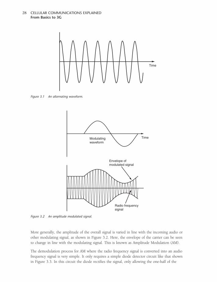
More generally, the amplitude of the overall signal is varied in line with the incoming audio or
other modulating signal, as shown in Figure 3.2. Here, the envelope of the carrier can be seen
to change in line with the modulating signal. This is known as Amplitude Modulation (AM).
The demodulation process for AM where the radio frequency signal is converted into an audio
frequency signal is very simple. It only requires a simple diode detector circuit like that shown
in Figure 3.3. In this circuit the diode rectifies the signal, only allowing the one-half of the
Envelope ofmodulated signal
Radio frequencysignal
TimeModulatingwaveform
Figure 3.2 An amplitude modulated signal.
Time
Figure 3.1 An alternating waveform.
CELLULAR COMMUNICATIONS EXPLAINEDFrom Basics to 3G
28
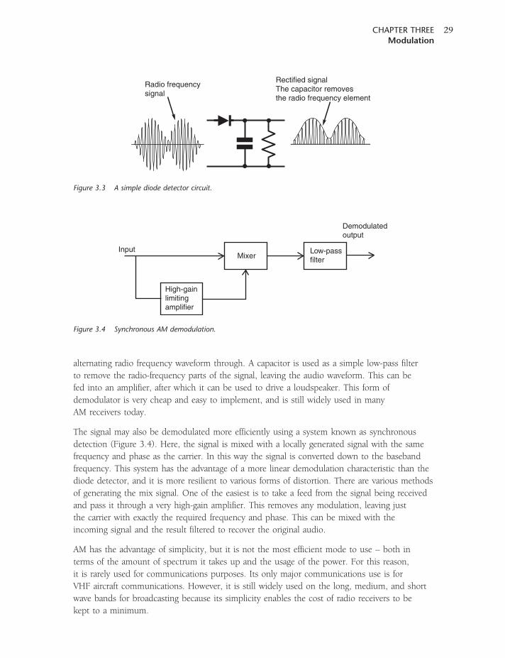
alternating radio frequency waveform through. A capacitor is used as a simple low-pass filter
to remove the radio-frequency parts of the signal, leaving the audio waveform. This can be
fed into an amplifier, after which it can be used to drive a loudspeaker. This form of
demodulator is very cheap and easy to implement, and is still widely used in many
AM receivers today.
The signal may also be demodulated more efficiently using a system known as synchronous
detection (Figure 3.4). Here, the signal is mixed with a locally generated signal with the same
frequency and phase as the carrier. In this way the signal is converted down to the baseband
frequency. This system has the advantage of a more linear demodulation characteristic than the
diode detector, and it is more resilient to various forms of distortion. There are various methods
of generating the mix signal. One of the easiest is to take a feed from the signal being received
and pass it through a very high-gain amplifier. This removes any modulation, leaving just
the carrier with exactly the required frequency and phase. This can be mixed with the
incoming signal and the result filtered to recover the original audio.
AM has the advantage of simplicity, but it is not the most efficient mode to use – both in
terms of the amount of spectrum it takes up and the usage of the power. For this reason,
it is rarely used for communications purposes. Its only major communications use is for
VHF aircraft communications. However, it is still widely used on the long, medium, and short
wave bands for broadcasting because its simplicity enables the cost of radio receivers to be
kept to a minimum.
Radio frequencysignal
Rectified signalThe capacitor removesthe radio frequency element
Figure 3.3 A simple diode detector circuit.
High-gainlimitingamplifier
MixerLow-passfilter
Input
Demodulatedoutput
Figure 3.4 Synchronous AM demodulation.
CHAPTER THREEModulation
29
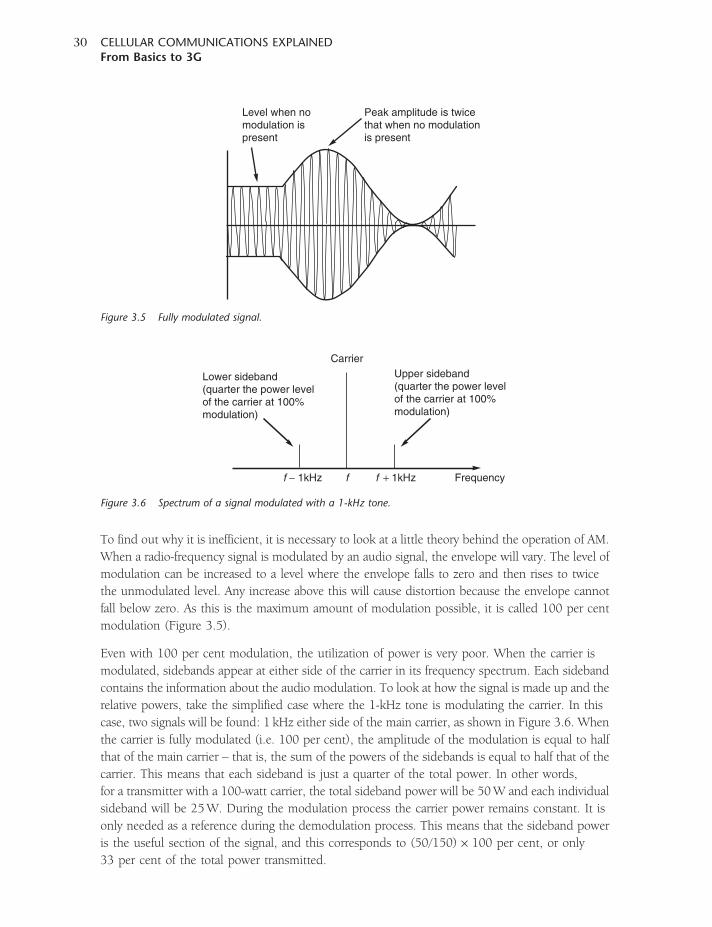
To find out why it is inefficient, it is necessary to look at a little theory behind the operation of AM.
When a radio-frequency signal is modulated by an audio signal, the envelope will vary. The level of
modulation can be increased to a level where the envelope falls to zero and then rises to twice
the unmodulated level. Any increase above this will cause distortion because the envelope cannot
fall below zero. As this is the maximum amount of modulation possible, it is called 100 per cent
modulation (Figure 3.5).
Even with 100 per cent modulation, the utilization of power is very poor. When the carrier is
modulated, sidebands appear at either side of the carrier in its frequency spectrum. Each sideband
contains the information about the audio modulation. To look at how the signal is made up and the
relative powers, take the simplified case where the 1-kHz tone is modulating the carrier. In this
case, two signals will be found: 1 kHz either side of the main carrier, as shown in Figure 3.6. When
the carrier is fully modulated (i.e. 100 per cent), the amplitude of the modulation is equal to half
that of the main carrier – that is, the sum of the powers of the sidebands is equal to half that of the
carrier. This means that each sideband is just a quarter of the total power. In other words,
for a transmitter with a 100-watt carrier, the total sideband power will be 50W and each individual
sideband will be 25W. During the modulation process the carrier power remains constant. It is
only needed as a reference during the demodulation process. This means that the sideband power
is the useful section of the signal, and this corresponds to (50/150)� 100 per cent, or only
33 per cent of the total power transmitted.
Level when nomodulation ispresent
Peak amplitude is twicethat when no modulationis present
Figure 3.5 Fully modulated signal.
Carrier
Frequency
Upper sideband(quarter the power levelof the carrier at 100%modulation)
Lower sideband(quarter the power levelof the carrier at 100%modulation)
ff − 1kHz f + 1kHz
Figure 3.6 Spectrum of a signal modulated with a 1-kHz tone.
CELLULAR COMMUNICATIONS EXPLAINEDFrom Basics to 3G
30
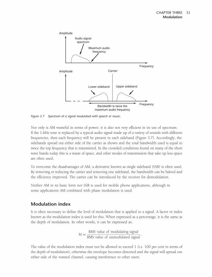
Not only is AM wasteful in terms of power; it is also not very efficient in its use of spectrum.
If the 1-kHz tone is replaced by a typical audio signal made up of a variety of sounds with different
frequencies, then each frequency will be present in each sideband (Figure 3.7). Accordingly, the
sidebands spread out either side of the carrier as shown and the total bandwidth used is equal to
twice the top frequency that is transmitted. In the crowded conditions found on many of the short
wave bands today this is a waste of space, and other modes of transmission that take up less space
are often used.
To overcome the disadvantages of AM, a derivative known as single sideband (SSB) is often used.
By removing or reducing the carrier and removing one sideband, the bandwidth can be halved and
the efficiency improved. The carrier can be introduced by the receiver for demodulation.
Neither AM in its basic form nor SSB is used for mobile phone applications, although in
some applications AM combined with phase modulation is used.
Modulation index
It is often necessary to define the level of modulation that is applied to a signal. A factor or index
known as the modulation index is used for this. When expressed as a percentage, it is the same as
the depth of modulation. In other words, it can be expressed as:
M ¼RMS value of modulating signal
RMS value of unmodulated signal:
The value of the modulation index must not be allowed to exceed 1 (i.e. 100 per cent in terms of
the depth of modulation), otherwise the envelope becomes distorted and the signal will spread out
either side of the wanted channel, causing interference to other users.
Frequency
Frequency
Audio signalspectrum
Maximum audiofrequency
Amplitude
Amplitude Carrier
Lower sideband Upper sideband
Bandwidth is twice themaximum audio frequency
Figure 3.7 Spectrum of a signal modulated with speech or music.
CHAPTER THREEModulation
31
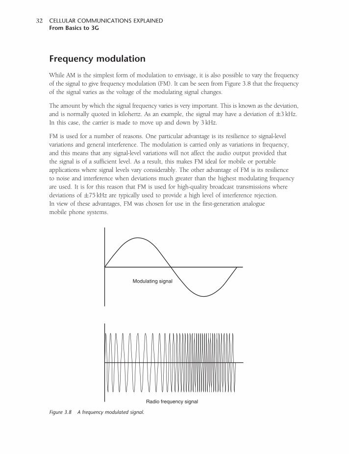
Frequency modulation
While AM is the simplest form of modulation to envisage, it is also possible to vary the frequency
of the signal to give frequency modulation (FM). It can be seen from Figure 3.8 that the frequency
of the signal varies as the voltage of the modulating signal changes.
The amount by which the signal frequency varies is very important. This is known as the deviation,
and is normally quoted in kilohertz. As an example, the signal may have a deviation of �3 kHz.
In this case, the carrier is made to move up and down by 3 kHz.
FM is used for a number of reasons. One particular advantage is its resilience to signal-level
variations and general interference. The modulation is carried only as variations in frequency,
and this means that any signal-level variations will not affect the audio output provided that
the signal is of a sufficient level. As a result, this makes FM ideal for mobile or portable
applications where signal levels vary considerably. The other advantage of FM is its resilience
to noise and interference when deviations much greater than the highest modulating frequency
are used. It is for this reason that FM is used for high-quality broadcast transmissions where
deviations of �75 kHz are typically used to provide a high level of interference rejection.
In view of these advantages, FM was chosen for use in the first-generation analogue
mobile phone systems.
Modulating signal
Radio frequency signal
Figure 3.8 A frequency modulated signal.
CELLULAR COMMUNICATIONS EXPLAINEDFrom Basics to 3G
32
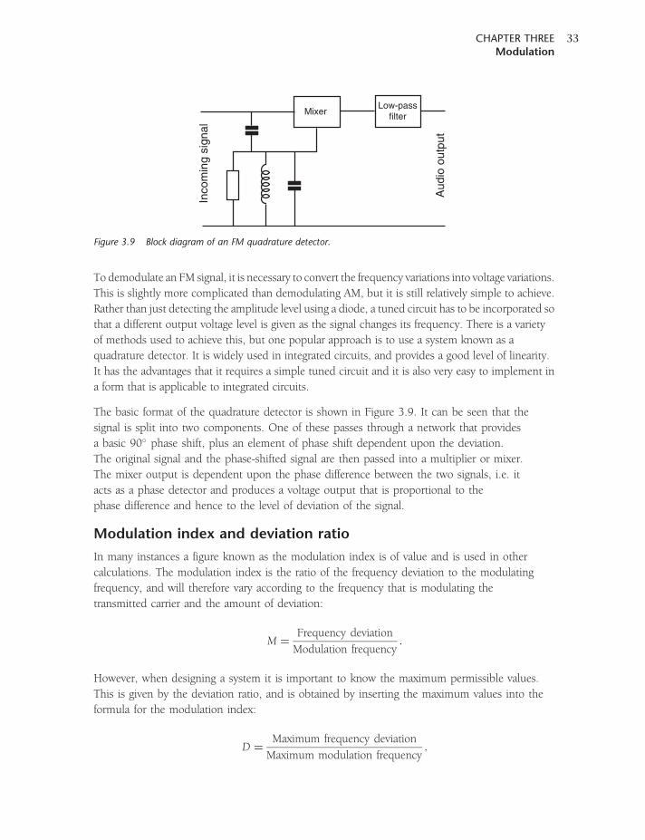
To demodulate an FM signal, it is necessary to convert the frequency variations into voltage variations.
This is slightly more complicated than demodulating AM, but it is still relatively simple to achieve.
Rather than just detecting the amplitude level using a diode, a tuned circuit has to be incorporated so
that a different output voltage level is given as the signal changes its frequency. There is a variety
of methods used to achieve this, but one popular approach is to use a system known as a
quadrature detector. It is widely used in integrated circuits, and provides a good level of linearity.
It has the advantages that it requires a simple tuned circuit and it is also very easy to implement in
a form that is applicable to integrated circuits.
The basic format of the quadrature detector is shown in Figure 3.9. It can be seen that the
signal is split into two components. One of these passes through a network that provides
a basic 90� phase shift, plus an element of phase shift dependent upon the deviation.
The original signal and the phase-shifted signal are then passed into a multiplier or mixer.
The mixer output is dependent upon the phase difference between the two signals, i.e. it
acts as a phase detector and produces a voltage output that is proportional to the
phase difference and hence to the level of deviation of the signal.
Modulation index and deviation ratio
In many instances a figure known as the modulation index is of value and is used in other
calculations. The modulation index is the ratio of the frequency deviation to the modulating
frequency, and will therefore vary according to the frequency that is modulating the
transmitted carrier and the amount of deviation:
M ¼Frequency deviation
Modulation frequency:
However, when designing a system it is important to know the maximum permissible values.
This is given by the deviation ratio, and is obtained by inserting the maximum values into the
formula for the modulation index:
D ¼Maximum frequency deviation
Maximum modulation frequency:
MixerLow-pass
filter
Inco
min
g si
gnal
Aud
io o
utpu
t
Figure 3.9 Block diagram of an FM quadrature detector.
CHAPTER THREEModulation
33
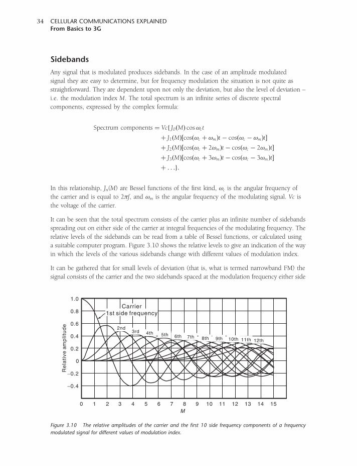
Sidebands
Any signal that is modulated produces sidebands. In the case of an amplitude modulated
signal they are easy to determine, but for frequency modulation the situation is not quite as
straightforward. They are dependent upon not only the deviation, but also the level of deviation –
i.e. the modulation index M. The total spectrum is an infinite series of discrete spectral
components, expressed by the complex formula:
Spectrum components ¼ Vcf J0ðMÞ cos!ct
þ J1ðMÞ½cosð!c þ !mÞt� cosð!c � !mÞt�
þ J2ðMÞ½cosð!c þ 2!mÞt� cosð!c � 2!mÞt�
þ J3ðMÞ½cosð!c þ 3!mÞt� cosð!c � 3!mÞt�
þ . . .g:
In this relationship, Jn(M) are Bessel functions of the first kind, !c is the angular frequency of
the carrier and is equal to 2�f, and !m is the angular frequency of the modulating signal. Vc is
the voltage of the carrier.
It can be seen that the total spectrum consists of the carrier plus an infinite number of sidebands
spreading out on either side of the carrier at integral frequencies of the modulating frequency. The
relative levels of the sidebands can be read from a table of Bessel functions, or calculated using
a suitable computer program. Figure 3.10 shows the relative levels to give an indication of the way
in which the levels of the various sidebands change with different values of modulation index.
It can be gathered that for small levels of deviation (that is, what is termed narrowband FM) the
signal consists of the carrier and the two sidebands spaced at the modulation frequency either side
2nd3rd 4th 5th 6th 7th 8th 9th 10th 11th 12th
1.0
0.8
0.6
0.4
0.2
0
−0.2
−0.4
0 1 2 3 4 5 6 7 8 9 10 11 12 13 14 15M
Re
lati
ve a
mp
litu
de
Carrier1st side frequency
Figure 3.10 The relative amplitudes of the carrier and the first 10 side frequency components of a frequency
modulated signal for different values of modulation index.
CELLULAR COMMUNICATIONS EXPLAINEDFrom Basics to 3G
34
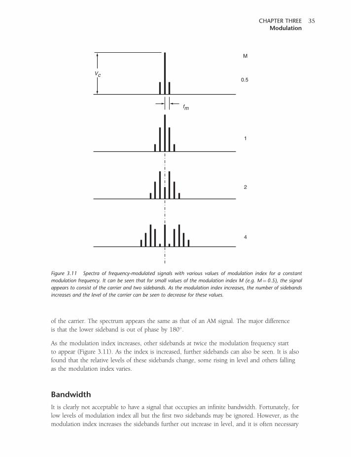
of the carrier. The spectrum appears the same as that of an AM signal. The major difference
is that the lower sideband is out of phase by 180�.
As the modulation index increases, other sidebands at twice the modulation frequency start
to appear (Figure 3.11). As the index is increased, further sidebands can also be seen. It is also
found that the relative levels of these sidebands change, some rising in level and others falling
as the modulation index varies.
Bandwidth
It is clearly not acceptable to have a signal that occupies an infinite bandwidth. Fortunately, for
low levels of modulation index all but the first two sidebands may be ignored. However, as the
modulation index increases the sidebands further out increase in level, and it is often necessary
fm
Vc
M
0.5
1
2
4
Figure 3.11 Spectra of frequency-modulated signals with various values of modulation index for a constant
modulation frequency. It can be seen that for small values of the modulation index M (e.g. M¼0.5), the signal
appears to consist of the carrier and two sidebands. As the modulation index increases, the number of sidebands
increases and the level of the carrier can be seen to decrease for these values.
CHAPTER THREEModulation
35
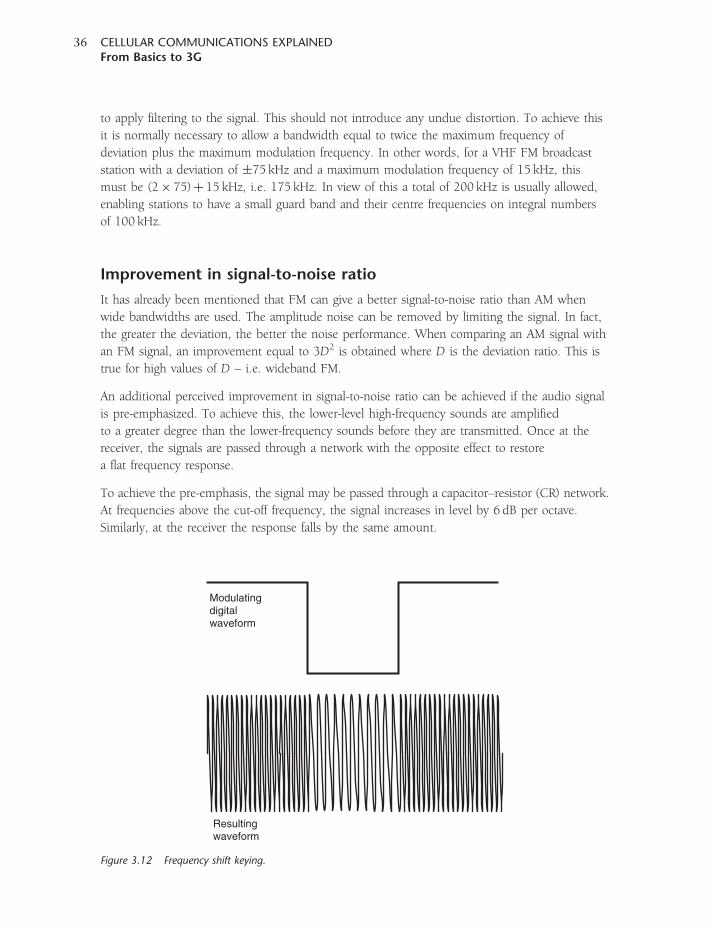
to apply filtering to the signal. This should not introduce any undue distortion. To achieve this
it is normally necessary to allow a bandwidth equal to twice the maximum frequency of
deviation plus the maximum modulation frequency. In other words, for a VHF FM broadcast
station with a deviation of �75 kHz and a maximum modulation frequency of 15 kHz, this
must be (2� 75)þ 15 kHz, i.e. 175 kHz. In view of this a total of 200 kHz is usually allowed,
enabling stations to have a small guard band and their centre frequencies on integral numbers
of 100 kHz.
Improvement in signal-to-noise ratio
It has already been mentioned that FM can give a better signal-to-noise ratio than AM when
wide bandwidths are used. The amplitude noise can be removed by limiting the signal. In fact,
the greater the deviation, the better the noise performance. When comparing an AM signal with
an FM signal, an improvement equal to 3D2 is obtained where D is the deviation ratio. This is
true for high values of D – i.e. wideband FM.
An additional perceived improvement in signal-to-noise ratio can be achieved if the audio signal
is pre-emphasized. To achieve this, the lower-level high-frequency sounds are amplified
to a greater degree than the lower-frequency sounds before they are transmitted. Once at the
receiver, the signals are passed through a network with the opposite effect to restore
a flat frequency response.
To achieve the pre-emphasis, the signal may be passed through a capacitor–resistor (CR) network.
At frequencies above the cut-off frequency, the signal increases in level by 6 dB per octave.
Similarly, at the receiver the response falls by the same amount.
Modulatingdigitalwaveform
Resulting waveform
Figure 3.12 Frequency shift keying.
CELLULAR COMMUNICATIONS EXPLAINEDFrom Basics to 3G
36
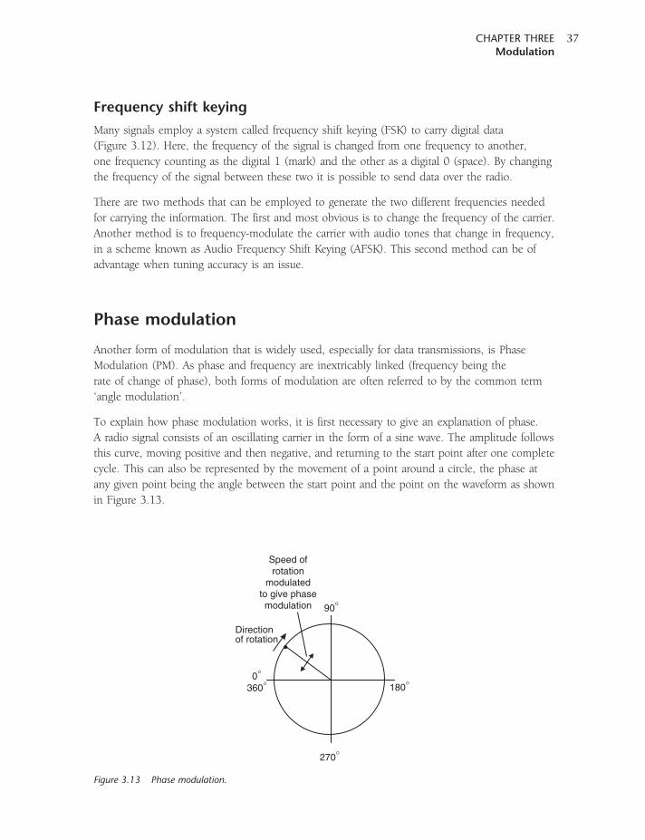
Frequency shift keying
Many signals employ a system called frequency shift keying (FSK) to carry digital data
(Figure 3.12). Here, the frequency of the signal is changed from one frequency to another,
one frequency counting as the digital 1 (mark) and the other as a digital 0 (space). By changing
the frequency of the signal between these two it is possible to send data over the radio.
There are two methods that can be employed to generate the two different frequencies needed
for carrying the information. The first and most obvious is to change the frequency of the carrier.
Another method is to frequency-modulate the carrier with audio tones that change in frequency,
in a scheme known as Audio Frequency Shift Keying (AFSK). This second method can be of
advantage when tuning accuracy is an issue.
Phase modulation
Another form of modulation that is widely used, especially for data transmissions, is Phase
Modulation (PM). As phase and frequency are inextricably linked (frequency being the
rate of change of phase), both forms of modulation are often referred to by the common term
‘angle modulation’.
To explain how phase modulation works, it is first necessary to give an explanation of phase.
A radio signal consists of an oscillating carrier in the form of a sine wave. The amplitude follows
this curve, moving positive and then negative, and returning to the start point after one complete
cycle. This can also be represented by the movement of a point around a circle, the phase at
any given point being the angle between the start point and the point on the waveform as shown
in Figure 3.13.
0°
90°
Directionof rotation
Speed ofrotation
modulatedto give phasemodulation
180°
270°
360°
Figure 3.13 Phase modulation.
CHAPTER THREEModulation
37
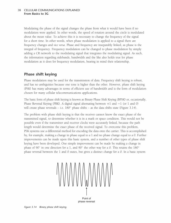
Modulating the phase of the signal changes the phase from what it would have been if no
modulation were applied. In other words, the speed of rotation around the circle is modulated
about the mean value. To achieve this it is necessary to change the frequency of the signal
for a short time. In other words, when phase modulation is applied to a signal there are
frequency changes and vice versa. Phase and frequency are inseparably linked, as phase is the
integral of frequency. Frequency modulation can be changed to phase modulation by simply
adding a CR network to the modulating signal that integrates the modulating signal. As such,
the information regarding sidebands, bandwidth and the like also holds true for phase
modulation as it does for frequency modulation, bearing in mind their relationship.
Phase shift keying
Phase modulation may be used for the transmission of data. Frequency shift keying is robust,
and has no ambiguities because one tone is higher than the other. However, phase shift keying
(PSK) has many advantages in terms of efficient use of bandwidth and is the form of modulation
chosen for many cellular telecommunications applications.
The basic form of phase shift keying is known as Binary Phase Shift Keying (BPSK) or, occasionally,
Phase Reversal Keying (PRK). A digital signal alternating between þ1 and �1 (or 1 and 0)
will create phase reversals – i.e. 180� phase shifts – as the data shifts state (Figure 3.14).
The problem with phase shift keying is that the receiver cannot know the exact phase of the
transmitted signal, to determine whether it is in a mark or space condition. This would not be
possible even if the transmitter and receiver clocks were accurately linked, because the path
length would determine the exact phase of the received signal. To overcome this problem,
PSK systems use a differential method for encoding the data onto the carrier. This is accomplished
by, for example, making a change in phase equal to a 1 and no phase change equal to a 0. Further
improvements can be made upon this basic system, and a number of other types of phase shift
keying have been developed. One simple improvement can be made by making a change in
phase of 90� in one direction for a 1, and 90� the other way for a 0. This retains the 180�
phase reversal between the 1 and 0 states, but gives a distinct change for a 0. In a basic system
Point ofphase reversal
Figure 3.14 Binary phase shift keying.
CELLULAR COMMUNICATIONS EXPLAINEDFrom Basics to 3G
38
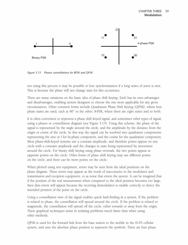
not using this process it may be possible to lose synchronization if a long series of zeros is sent.
This is because the phase will not change state for this occurrence.
There are many variations on the basic idea of phase shift keying. Each has its own advantages
and disadvantages, enabling system designers to choose the one most applicable for any given
circumstances. Other common forms include Quadrature Phase Shift Keying (QPSK), where four
phase states are used, each at 90� to the other; 8-PSK, where there are eight states and so forth.
It is often convenient to represent a phase shift keyed signal, and sometimes other types of signal,
using a phasor or constellation diagram (see Figure 3.15). Using this scheme, the phase of the
signal is represented by the angle around the circle, and the amplitude by the distance from the
origin or centre of the circle. In this way the signal can be resolved into quadrature components
representing the sine or I for In-phase component, and the cosine for the quadrature component.
Most phase-shift-keyed systems use a constant amplitude, and therefore points appear on one
circle with a constant amplitude and the changes in state being represented by movement
around the circle. For binary shift keying using phase reversals, the two points appear at
opposite points on the circle. Other forms of phase shift keying may use different points
on the circle, and there can be more points on the circle.
When plotted using test equipment, errors may be seen from the ideal positions on the
phase diagram. These errors may appear as the result of inaccuracies in the modulator and
transmission and reception equipment, or as noise that enters the system. It can be imagined that
if the position of the real measurement when compared to the ideal position becomes too large,
then data errors will appear because the receiving demodulator is unable correctly to detect the
intended position of the point on the circle.
Using a constellation view of the signal enables quick fault-finding in a system. If the problem
is related to phase, the constellation will spread around the circle. If the problem is related to
magnitude, the constellation will spread off the circle, either towards or away from the origin.
These graphical techniques assist in isolating problems much faster than when using
other methods.
QPSK is used for the forward link from the base station to the mobile in the IS-95 cellular
system, and uses the absolute phase position to represent the symbols. There are four phase
Q
11
10
1
01
00
0 4-phase PSK
Binary PSK
Figure 3.15 Phasor constellations for BPSK and QPSK.
CHAPTER THREEModulation
39
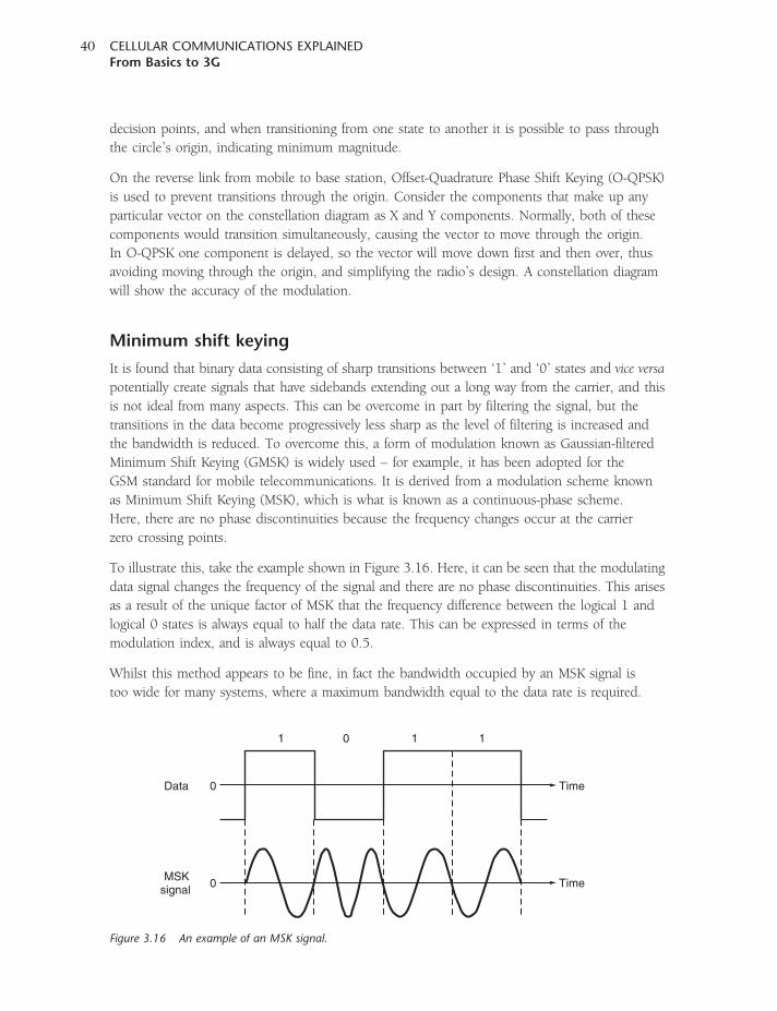
decision points, and when transitioning from one state to another it is possible to pass through
the circle’s origin, indicating minimum magnitude.
On the reverse link from mobile to base station, Offset-Quadrature Phase Shift Keying (O-QPSK)
is used to prevent transitions through the origin. Consider the components that make up any
particular vector on the constellation diagram as X and Y components. Normally, both of these
components would transition simultaneously, causing the vector to move through the origin.
In O-QPSK one component is delayed, so the vector will move down first and then over, thus
avoiding moving through the origin, and simplifying the radio’s design. A constellation diagram
will show the accuracy of the modulation.
Minimum shift keying
It is found that binary data consisting of sharp transitions between ‘1’ and ‘0’ states and vice versa
potentially create signals that have sidebands extending out a long way from the carrier, and this
is not ideal from many aspects. This can be overcome in part by filtering the signal, but the
transitions in the data become progressively less sharp as the level of filtering is increased and
the bandwidth is reduced. To overcome this, a form of modulation known as Gaussian-filtered
Minimum Shift Keying (GMSK) is widely used – for example, it has been adopted for the
GSM standard for mobile telecommunications. It is derived from a modulation scheme known
as Minimum Shift Keying (MSK), which is what is known as a continuous-phase scheme.
Here, there are no phase discontinuities because the frequency changes occur at the carrier
zero crossing points.
To illustrate this, take the example shown in Figure 3.16. Here, it can be seen that the modulating
data signal changes the frequency of the signal and there are no phase discontinuities. This arises
as a result of the unique factor of MSK that the frequency difference between the logical 1 and
logical 0 states is always equal to half the data rate. This can be expressed in terms of the
modulation index, and is always equal to 0.5.
Whilst this method appears to be fine, in fact the bandwidth occupied by an MSK signal is
too wide for many systems, where a maximum bandwidth equal to the data rate is required.
1 0 1 1
Data 0
0MSK
signal
Time
Time
Figure 3.16 An example of an MSK signal.
CELLULAR COMMUNICATIONS EXPLAINEDFrom Basics to 3G
40
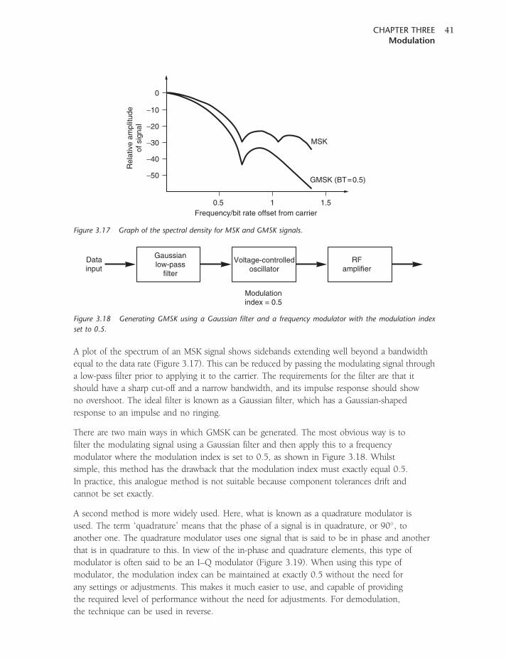
A plot of the spectrum of an MSK signal shows sidebands extending well beyond a bandwidth
equal to the data rate (Figure 3.17). This can be reduced by passing the modulating signal through
a low-pass filter prior to applying it to the carrier. The requirements for the filter are that it
should have a sharp cut-off and a narrow bandwidth, and its impulse response should show
no overshoot. The ideal filter is known as a Gaussian filter, which has a Gaussian-shaped
response to an impulse and no ringing.
There are two main ways in which GMSK can be generated. The most obvious way is to
filter the modulating signal using a Gaussian filter and then apply this to a frequency
modulator where the modulation index is set to 0.5, as shown in Figure 3.18. Whilst
simple, this method has the drawback that the modulation index must exactly equal 0.5.
In practice, this analogue method is not suitable because component tolerances drift and
cannot be set exactly.
A second method is more widely used. Here, what is known as a quadrature modulator is
used. The term ‘quadrature’ means that the phase of a signal is in quadrature, or 90�, to
another one. The quadrature modulator uses one signal that is said to be in phase and another
that is in quadrature to this. In view of the in-phase and quadrature elements, this type of
modulator is often said to be an I–Q modulator (Figure 3.19). When using this type of
modulator, the modulation index can be maintained at exactly 0.5 without the need for
any settings or adjustments. This makes it much easier to use, and capable of providing
the required level of performance without the need for adjustments. For demodulation,
the technique can be used in reverse.
0
−10
−20
−30
−40
−50
Rel
ativ
e am
plitu
deof
sig
nal
Frequency/bit rate offset from carrier0.5 1 1.5
MSK
GMSK (BT=0.5)
Figure 3.17 Graph of the spectral density for MSK and GMSK signals.
Voltage-controlledoscillator
Modulationindex = 0.5
Gaussianlow-pass
filter
RFamplifier
Datainput
Figure 3.18 Generating GMSK using a Gaussian filter and a frequency modulator with the modulation index
set to 0.5.
CHAPTER THREEModulation
41
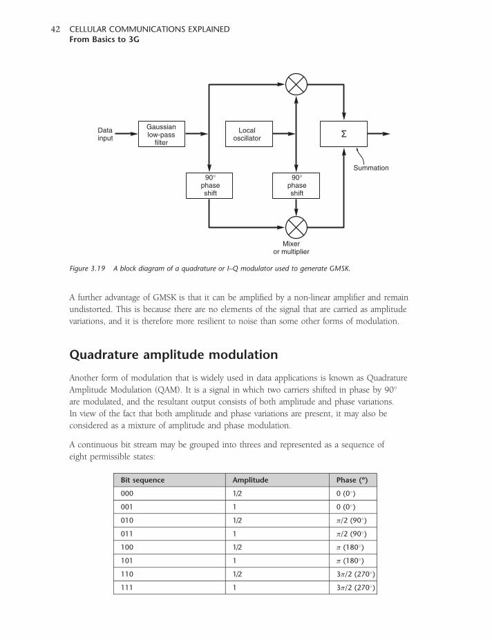
A further advantage of GMSK is that it can be amplified by a non-linear amplifier and remain
undistorted. This is because there are no elements of the signal that are carried as amplitude
variations, and it is therefore more resilient to noise than some other forms of modulation.
Quadrature amplitude modulation
Another form of modulation that is widely used in data applications is known as Quadrature
Amplitude Modulation (QAM). It is a signal in which two carriers shifted in phase by 90�
are modulated, and the resultant output consists of both amplitude and phase variations.
In view of the fact that both amplitude and phase variations are present, it may also be
considered as a mixture of amplitude and phase modulation.
A continuous bit stream may be grouped into threes and represented as a sequence of
eight permissible states:
Gaussianlow-pass
filter
Localoscillator
Datainput
90°phaseshift
90°phaseshift
Mixeror multiplier
Summation
Figure 3.19 A block diagram of a quadrature or I–Q modulator used to generate GMSK.
Bit sequence Amplitude Phase (º)
000 1/2 0 (0�)
001 1 0 (0�)
010 1/2 �/2 (90�)
011 1 �/2 (90�)
100 1/2 � (180�)
101 1 � (180�)
110 1/2 3�/2 (270�)
111 1 3�/2 (270�)
CELLULAR COMMUNICATIONS EXPLAINEDFrom Basics to 3G
42
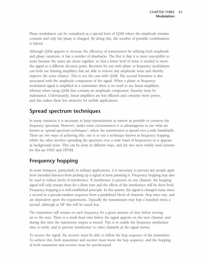
Phase modulation can be considered as a special form of QAM where the amplitude remains
constant and only the phase is changed. By doing this, the number of possible combinations
is halved.
Although QAM appears to increase the efficiency of transmission by utilizing both amplitude
and phase variations, it has a number of drawbacks. The first is that it is more susceptible to
noise because the states are closer together, so that a lower level of noise is needed to move
the signal to a different decision point. Receivers for use with phase or frequency modulation
can both use limiting amplifiers that are able to remove any amplitude noise and thereby
improve the noise reliance. This is not the case with QAM. The second limitation is also
associated with the amplitude component of the signal. When a phase or frequency
modulated signal is amplified in a transmitter there is no need to use linear amplifiers,
whereas when using QAM that contains an amplitude component, linearity must be
maintained. Unfortunately, linear amplifiers are less efficient and consume more power,
and this makes them less attractive for mobile applications.
Spread spectrum techniques
In many instances it is necessary to keep transmissions as narrow as possible to conserve the
frequency spectrum. However, under some circumstances it is advantageous to use what are
known as ‘spread spectrum techniques’, where the transmission is spread over a wide bandwidth.
There are two ways of achieving this: one is to use a technique known as frequency hopping,
whilst the other involves spreading the spectrum over a wide band of frequencies so it appears
as background noise. This can be done in different ways, and the two most widely used systems
for this are DSSS and OFDM.
Frequency hopping
In some instances, particularly in military applications, it is necessary to prevent any people apart
from intended listeners from picking up a signal or from jamming it. Frequency hopping may also
be used to reduce levels of interference. If interference is present on one channel, the hopping
signal will only remain there for a short time and the effects of the interference will be short lived.
Frequency hopping is a well-established principle. In this system, the signal is changed many times
a second in a pseudo-random sequence from a predefined block of channels. Hop rates vary, and
are dependent upon the requirements. Typically the transmission may hop a hundred times a
second, although at HF this will be much less.
The transmitter will remain on each frequency for a given amount of time before moving
on to the next. There is a small dead time before the signal appears on the next channel, and
during this time the transmitter output is muted. This is to enable the frequency synthesizer
time to settle, and to prevent interference to other channels as the signal moves.
To receive the signal, the receiver must be able to follow the hop sequence of the transmitter.
To achieve this, both transmitter and receiver must know the hop sequence, and the hopping
of both transmitter and receiver must be synchronized.
CHAPTER THREEModulation
43
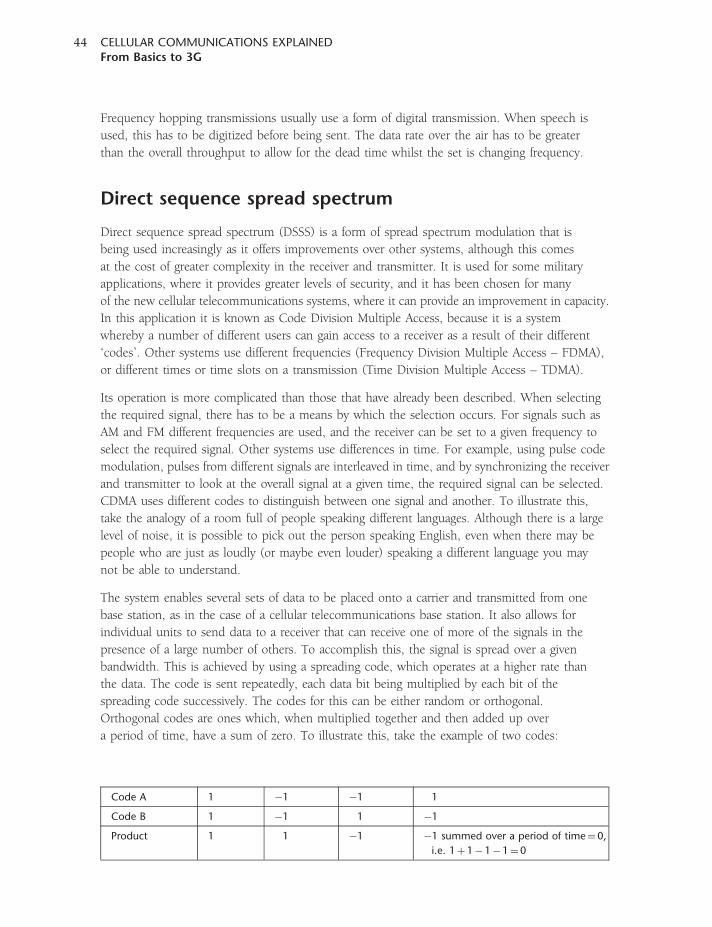
Frequency hopping transmissions usually use a form of digital transmission. When speech is
used, this has to be digitized before being sent. The data rate over the air has to be greater
than the overall throughput to allow for the dead time whilst the set is changing frequency.
Direct sequence spread spectrum
Direct sequence spread spectrum (DSSS) is a form of spread spectrum modulation that is
being used increasingly as it offers improvements over other systems, although this comes
at the cost of greater complexity in the receiver and transmitter. It is used for some military
applications, where it provides greater levels of security, and it has been chosen for many
of the new cellular telecommunications systems, where it can provide an improvement in capacity.
In this application it is known as Code Division Multiple Access, because it is a system
whereby a number of different users can gain access to a receiver as a result of their different
‘codes’. Other systems use different frequencies (Frequency Division Multiple Access – FDMA),
or different times or time slots on a transmission (Time Division Multiple Access – TDMA).
Its operation is more complicated than those that have already been described. When selecting
the required signal, there has to be a means by which the selection occurs. For signals such as
AM and FM different frequencies are used, and the receiver can be set to a given frequency to
select the required signal. Other systems use differences in time. For example, using pulse code
modulation, pulses from different signals are interleaved in time, and by synchronizing the receiver
and transmitter to look at the overall signal at a given time, the required signal can be selected.
CDMA uses different codes to distinguish between one signal and another. To illustrate this,
take the analogy of a room full of people speaking different languages. Although there is a large
level of noise, it is possible to pick out the person speaking English, even when there may be
people who are just as loudly (or maybe even louder) speaking a different language you may
not be able to understand.
The system enables several sets of data to be placed onto a carrier and transmitted from one
base station, as in the case of a cellular telecommunications base station. It also allows for
individual units to send data to a receiver that can receive one of more of the signals in the
presence of a large number of others. To accomplish this, the signal is spread over a given
bandwidth. This is achieved by using a spreading code, which operates at a higher rate than
the data. The code is sent repeatedly, each data bit being multiplied by each bit of the
spreading code successively. The codes for this can be either random or orthogonal.
Orthogonal codes are ones which, when multiplied together and then added up over
a period of time, have a sum of zero. To illustrate this, take the example of two codes:
Code A 1 �1 �1 1
Code B 1 �1 1 �1
Product 1 1 �1 �1 summed over a period of time¼0,
i.e. 1þ1�1�1¼0
CELLULAR COMMUNICATIONS EXPLAINEDFrom Basics to 3G
44
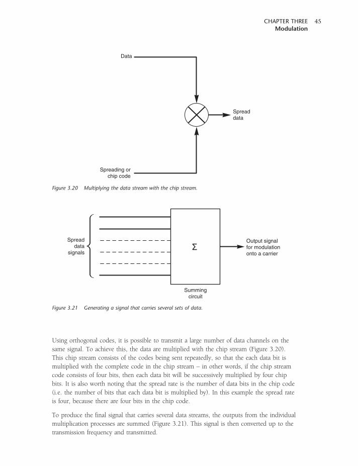
Using orthogonal codes, it is possible to transmit a large number of data channels on the
same signal. To achieve this, the data are multiplied with the chip stream (Figure 3.20).
This chip stream consists of the codes being sent repeatedly, so that the each data bit is
multiplied with the complete code in the chip stream – in other words, if the chip stream
code consists of four bits, then each data bit will be successively multiplied by four chip
bits. It is also worth noting that the spread rate is the number of data bits in the chip code
(i.e. the number of bits that each data bit is multiplied by). In this example the spread rate
is four, because there are four bits in the chip code.
To produce the final signal that carries several data streams, the outputs from the individual
multiplication processes are summed (Figure 3.21). This signal is then converted up to the
transmission frequency and transmitted.
Data
Spreading orchip code
Spreaddata
Figure 3.20 Multiplying the data stream with the chip stream.
Spreaddata
signals
Output signalfor modulationonto a carrier
Summingcircuit
Figure 3.21 Generating a signal that carries several sets of data.
CHAPTER THREEModulation
45
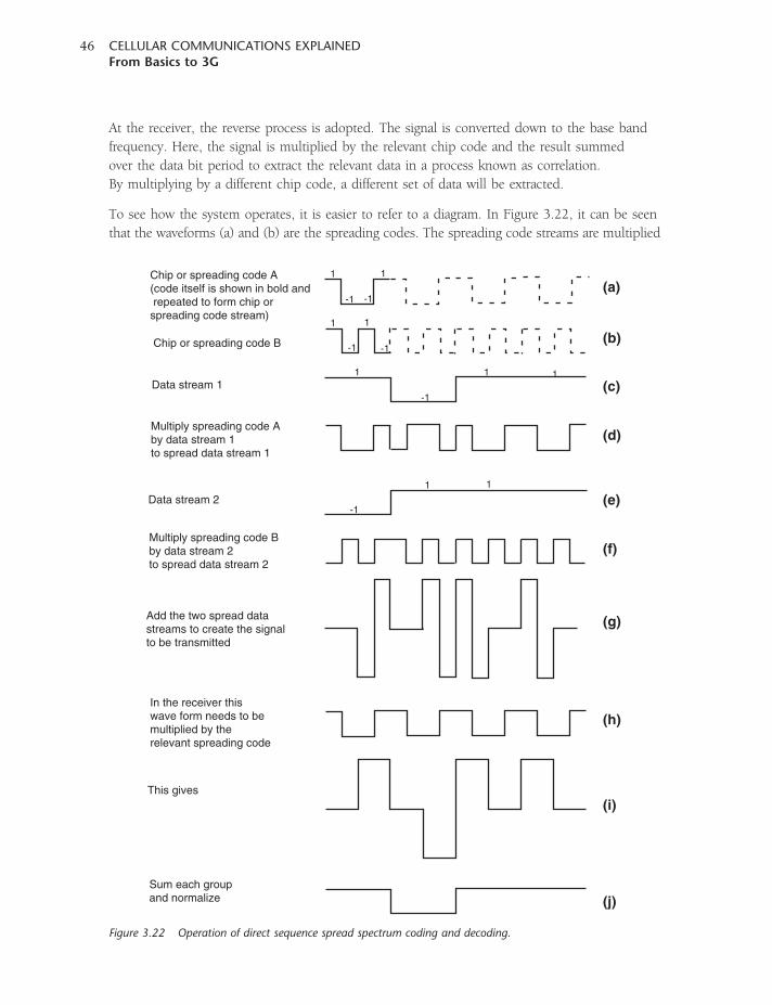
At the receiver, the reverse process is adopted. The signal is converted down to the base band
frequency. Here, the signal is multiplied by the relevant chip code and the result summed
over the data bit period to extract the relevant data in a process known as correlation.
By multiplying by a different chip code, a different set of data will be extracted.
To see how the system operates, it is easier to refer to a diagram. In Figure 3.22, it can be seen
that the waveforms (a) and (b) are the spreading codes. The spreading code streams are multiplied
Chip or spreading code A(code itself is shown in bold and repeated to form chip orspreading code stream)
1
1
11
111
1
1
-1 -1
-1
-1
-1
-1Chip or spreading code B
Data stream 1
Multiply spreading code Aby data stream 1to spread data stream 1
Multiply spreading code Bby data stream 2to spread data stream 2
Data stream 2
Add the two spread datastreams to create the signalto be transmitted
In the receiver thiswave form needs to bemultiplied by therelevant spreading code
This gives
Sum each groupand normalize
(a)
(b)
(c)
(d)
(e)
(f)
(g)
(h)
(i)
(j)
Figure 3.22 Operation of direct sequence spread spectrum coding and decoding.
CELLULAR COMMUNICATIONS EXPLAINEDFrom Basics to 3G
46
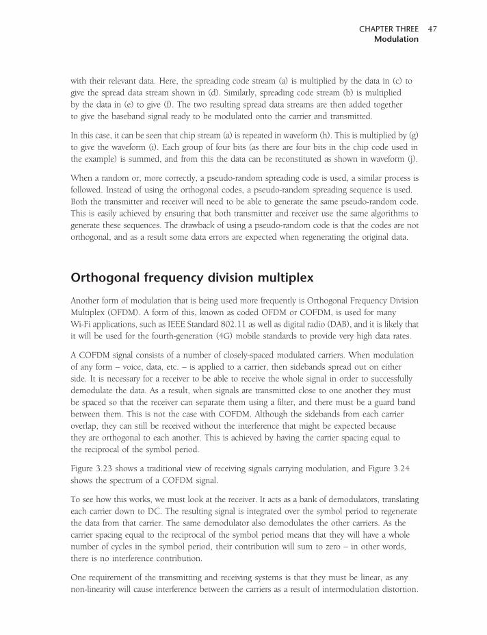
with their relevant data. Here, the spreading code stream (a) is multiplied by the data in (c) to
give the spread data stream shown in (d). Similarly, spreading code stream (b) is multiplied
by the data in (e) to give (f). The two resulting spread data streams are then added together
to give the baseband signal ready to be modulated onto the carrier and transmitted.
In this case, it can be seen that chip stream (a) is repeated in waveform (h). This is multiplied by (g)
to give the waveform (i). Each group of four bits (as there are four bits in the chip code used in
the example) is summed, and from this the data can be reconstituted as shown in waveform (j).
When a random or, more correctly, a pseudo-random spreading code is used, a similar process is
followed. Instead of using the orthogonal codes, a pseudo-random spreading sequence is used.
Both the transmitter and receiver will need to be able to generate the same pseudo-random code.
This is easily achieved by ensuring that both transmitter and receiver use the same algorithms to
generate these sequences. The drawback of using a pseudo-random code is that the codes are not
orthogonal, and as a result some data errors are expected when regenerating the original data.
Orthogonal frequency division multiplex
Another form of modulation that is being used more frequently is Orthogonal Frequency Division
Multiplex (OFDM). A form of this, known as coded OFDM or COFDM, is used for many
Wi-Fi applications, such as IEEE Standard 802.11 as well as digital radio (DAB), and it is likely that
it will be used for the fourth-generation (4G) mobile standards to provide very high data rates.
A COFDM signal consists of a number of closely-spaced modulated carriers. When modulation
of any form – voice, data, etc. – is applied to a carrier, then sidebands spread out on either
side. It is necessary for a receiver to be able to receive the whole signal in order to successfully
demodulate the data. As a result, when signals are transmitted close to one another they must
be spaced so that the receiver can separate them using a filter, and there must be a guard band
between them. This is not the case with COFDM. Although the sidebands from each carrier
overlap, they can still be received without the interference that might be expected because
they are orthogonal to each another. This is achieved by having the carrier spacing equal to
the reciprocal of the symbol period.
Figure 3.23 shows a traditional view of receiving signals carrying modulation, and Figure 3.24
shows the spectrum of a COFDM signal.
To see how this works, we must look at the receiver. It acts as a bank of demodulators, translating
each carrier down to DC. The resulting signal is integrated over the symbol period to regenerate
the data from that carrier. The same demodulator also demodulates the other carriers. As the
carrier spacing equal to the reciprocal of the symbol period means that they will have a whole
number of cycles in the symbol period, their contribution will sum to zero – in other words,
there is no interference contribution.
One requirement of the transmitting and receiving systems is that they must be linear, as any
non-linearity will cause interference between the carriers as a result of intermodulation distortion.
CHAPTER THREEModulation
47
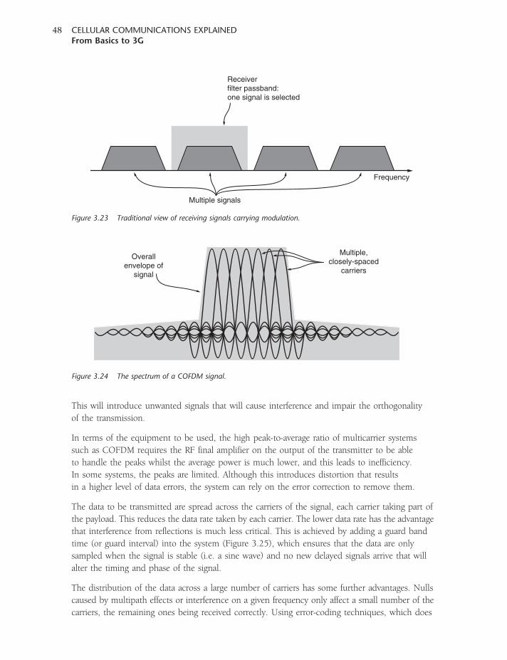
This will introduce unwanted signals that will cause interference and impair the orthogonality
of the transmission.
In terms of the equipment to be used, the high peak-to-average ratio of multicarrier systems
such as COFDM requires the RF final amplifier on the output of the transmitter to be able
to handle the peaks whilst the average power is much lower, and this leads to inefficiency.
In some systems, the peaks are limited. Although this introduces distortion that results
in a higher level of data errors, the system can rely on the error correction to remove them.
The data to be transmitted are spread across the carriers of the signal, each carrier taking part of
the payload. This reduces the data rate taken by each carrier. The lower data rate has the advantage
that interference from reflections is much less critical. This is achieved by adding a guard band
time (or guard interval) into the system (Figure 3.25), which ensures that the data are only
sampled when the signal is stable (i.e. a sine wave) and no new delayed signals arrive that will
alter the timing and phase of the signal.
The distribution of the data across a large number of carriers has some further advantages. Nulls
caused by multipath effects or interference on a given frequency only affect a small number of the
carriers, the remaining ones being received correctly. Using error-coding techniques, which does
Receiverfilter passband:one signal is selected
Multiple signals
Frequency
Figure 3.23 Traditional view of receiving signals carrying modulation.
Overallenvelope of
signal
Multiple,closely-spaced
carriers
Figure 3.24 The spectrum of a COFDM signal.
CELLULAR COMMUNICATIONS EXPLAINEDFrom Basics to 3G
48
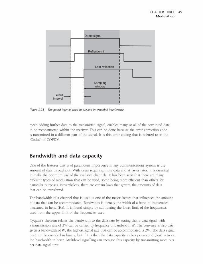
mean adding further data to the transmitted signal, enables many or all of the corrupted data
to be reconstructed within the receiver. This can be done because the error correction code
is transmitted in a different part of the signal. It is this error coding that is referred to in the
‘Coded’ of COFDM.
Bandwidth and data capacity
One of the features that is of paramount importance in any communications system is the
amount of data throughput. With users requiring more data and at faster rates, it is essential
to make the optimum use of the available channels. It has been seen that there are many
different types of modulation that can be used, some being more efficient than others for
particular purposes. Nevertheless, there are certain laws that govern the amounts of data
that can be transferred.
The bandwidth of a channel that is used is one of the major factors that influences the amount
of data that can be accommodated. Bandwidth is literally the width of a band of frequencies
measured in hertz (Hz). It is found simply by subtracting the lower limit of the frequencies
used from the upper limit of the frequencies used.
Nyquist’s theorem relates the bandwidth to the data rate by stating that a data signal with
a transmission rate of 2W can be carried by frequency of bandwidth W. The converse is also true:
given a bandwidth of W, the highest signal rate that can be accommodated is 2W. The data signal
need not be encoded in binary, but if it is then the data capacity in bits per second (bps) is twice
the bandwidth in hertz. Multilevel signalling can increase this capacity by transmitting more bits
per data signal unit.
Direct signal
Reflection 1
Last reflection
Samplingwindow
Guardinterval
Figure 3.25 The guard interval used to prevent intersymbol interference.
CHAPTER THREEModulation
49
The problem with multilevel signalling is that it must be possible to distinguish between the different
signalling levels in the presence of outside interference – in particular, noise. A law known as
Shannon’s Law defines the way in which this occurs. It was formulated by Claude Shannon,
a mathematician who helped build the foundations for the modern computer, and it is a statement
of information theory that expresses the maximum possible data speed that can be obtained
in a data channel. Shannon’s Law says that the highest obtainable error-free data speed is dependent
upon the bandwidth and the signal-to-noise ratio. It is usually expressed in the form:
C ¼ W log2ð1þ S=NÞ
where C is the channel capacity in bits per second, W is the bandwidth in hertz and S/N is the
signal-to-noise ratio.
Theoretically, it should be possible to obtain between 2 and 12 bps/Hz, but generally this cannot
be achieved and figures of between 1 and 4 bps/Hz are more reasonable. As a matter of simplicity,
no attempt will be made here to provide a serious distinction between the two kinds of ways
of measuring capacity and we will simply talk about ‘bandwidth’ in terms of bits per second.
However, it must be remembered that bandwidth and digital data rate are two different quantities.
Bandwidth is a measure of the range of frequencies used in an analogue signal, and bits per second
is a measure of the digital data rate.
Error correction codes can improve the communications performance relative to un-coded
transmissions, but no practical error correction coding system exists that can closely approach
the theoretical performance limit given by Shannon’s Law.
Summary
There are three ways in which a signal can be modulated: its amplitude, phase or frequency
can be varied, although of these phase and frequency are essentially the same. However, there
are a great many ways in which this can be achieved, and each type has its advantages and
disadvantages. Accordingly, the choice of the correct type of modulation is critical
when designing a new system.
CELLULAR COMMUNICATIONS EXPLAINEDFrom Basics to 3G
50
4CHAPTER FOUR
Cellular basics
There are many different cellular radio or cellular telecommunications systems in use around
the world. Naturally, they have many differences in the way they operate. Not only are there
different implementations of similar technologies, but over the years there have also been
developments in the technologies that are used. The first analogue systems gave way to digital
systems, and in turn these are being migrated to technologies that are able to carry much
higher data-rate signals to cope with the new applications that are being found. Yet despite
these differences there are some fundamental concepts that are at the core of cellular
telecommunications technology.
Spectrum re-use
One of the key requirements for any radio-based telecommunications system is the efficient use
of the frequencies that are available. Early schemes for radio telephones used a single central
transmitter to cover a wide area. These suffered from the limited number of channels that were
available, with waiting lists for connection being many times greater than the number of people
that were actually connected. This arose from the way the system was operated.
Take, for example, a system where each user is allocated a channel. Using a typical analogue
system, each channel needs to have a bandwidth of around 25 kHz to enable sufficient
audio quality to be carried, as well as allowing for a guard band between adjacent signals to ensure
there are no undue levels of interference. Using this concept, it is possible to accommodate only
forty users in a frequency band 1-MHz wide. Even if 100MHz were allocated to the system,
this would enable only 4000 users to have access to the system. Today cellular systems have
millions of subscribers, and therefore a far more efficient method of using the available spectrum
is needed.
The method that is employed is to enable the frequencies to be re-used. Any transmitter will
have only a certain coverage area, and beyond this the signal level will fall to a limit below which
it cannot be used and will not cause significant interference to users associated with a different
transmitter (Figure 4.1). This means that it is possible to re-use a channel once outside the range
of the transmitter. The same is also true in the reverse direction for the receiver, where it will be able
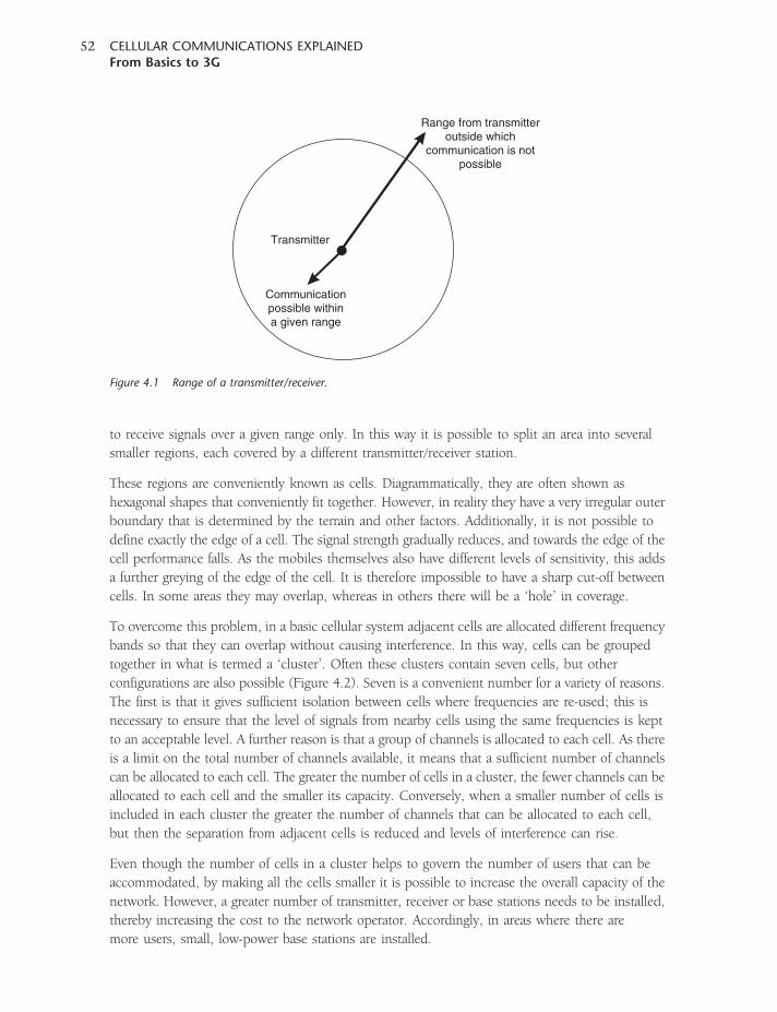
to receive signals over a given range only. In this way it is possible to split an area into several
smaller regions, each covered by a different transmitter/receiver station.
These regions are conveniently known as cells. Diagrammatically, they are often shown as
hexagonal shapes that conveniently fit together. However, in reality they have a very irregular outer
boundary that is determined by the terrain and other factors. Additionally, it is not possible to
define exactly the edge of a cell. The signal strength gradually reduces, and towards the edge of the
cell performance falls. As the mobiles themselves also have different levels of sensitivity, this adds
a further greying of the edge of the cell. It is therefore impossible to have a sharp cut-off between
cells. In some areas they may overlap, whereas in others there will be a ‘hole’ in coverage.
To overcome this problem, in a basic cellular system adjacent cells are allocated different frequency
bands so that they can overlap without causing interference. In this way, cells can be grouped
together in what is termed a ‘cluster’. Often these clusters contain seven cells, but other
configurations are also possible (Figure 4.2). Seven is a convenient number for a variety of reasons.
The first is that it gives sufficient isolation between cells where frequencies are re-used; this is
necessary to ensure that the level of signals from nearby cells using the same frequencies is kept
to an acceptable level. A further reason is that a group of channels is allocated to each cell. As there
is a limit on the total number of channels available, it means that a sufficient number of channels
can be allocated to each cell. The greater the number of cells in a cluster, the fewer channels can be
allocated to each cell and the smaller its capacity. Conversely, when a smaller number of cells is
included in each cluster the greater the number of channels that can be allocated to each cell,
but then the separation from adjacent cells is reduced and levels of interference can rise.
Even though the number of cells in a cluster helps to govern the number of users that can be
accommodated, by making all the cells smaller it is possible to increase the overall capacity of the
network. However, a greater number of transmitter, receiver or base stations needs to be installed,
thereby increasing the cost to the network operator. Accordingly, in areas where there are
more users, small, low-power base stations are installed.
Transmitter
Range from transmitteroutside which
communication is notpossible
Communicationpossible withina given range
Figure 4.1 Range of a transmitter/receiver.
CELLULAR COMMUNICATIONS EXPLAINEDFrom Basics to 3G
52
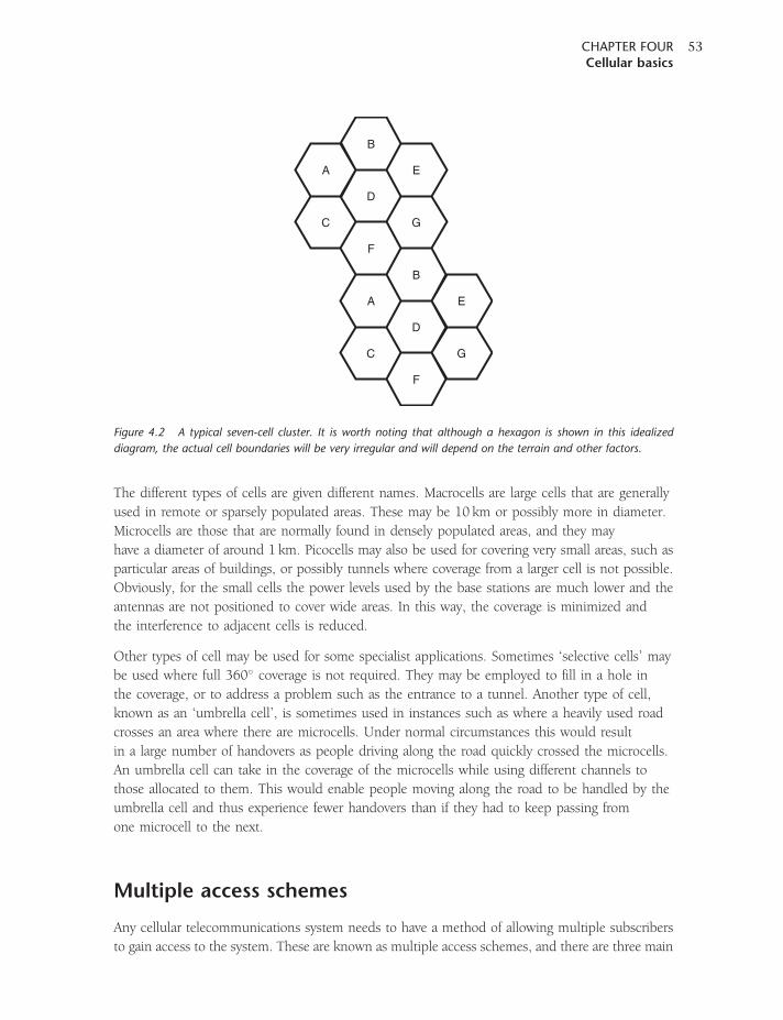
The different types of cells are given different names. Macrocells are large cells that are generally
used in remote or sparsely populated areas. These may be 10 km or possibly more in diameter.
Microcells are those that are normally found in densely populated areas, and they may
have a diameter of around 1 km. Picocells may also be used for covering very small areas, such as
particular areas of buildings, or possibly tunnels where coverage from a larger cell is not possible.
Obviously, for the small cells the power levels used by the base stations are much lower and the
antennas are not positioned to cover wide areas. In this way, the coverage is minimized and
the interference to adjacent cells is reduced.
Other types of cell may be used for some specialist applications. Sometimes ‘selective cells’ may
be used where full 360� coverage is not required. They may be employed to fill in a hole in
the coverage, or to address a problem such as the entrance to a tunnel. Another type of cell,
known as an ‘umbrella cell’, is sometimes used in instances such as where a heavily used road
crosses an area where there are microcells. Under normal circumstances this would result
in a large number of handovers as people driving along the road quickly crossed the microcells.
An umbrella cell can take in the coverage of the microcells while using different channels to
those allocated to them. This would enable people moving along the road to be handled by the
umbrella cell and thus experience fewer handovers than if they had to keep passing from
one microcell to the next.
Multiple access schemes
Any cellular telecommunications system needs to have a method of allowing multiple subscribers
to gain access to the system. These are known as multiple access schemes, and there are three main
A
A
D
D
C
C
F
F
G
G
E
E
B
B
Figure 4.2 A typical seven-cell cluster. It is worth noting that although a hexagon is shown in this idealized
diagram, the actual cell boundaries will be very irregular and will depend on the terrain and other factors.
CHAPTER FOURCellular basics
53

methods that are in use: Frequency Division Multiple Access (FDMA), Time Division Multiple
Access (TDMA) and Code Division Multiple Access (CDMA).
The first of the schemes to be used was FDMA. This scheme is the most straightforward.
As a subscriber comes onto the system, or swaps from one cell to the next, the network allocates
a channel or frequency to each one (Figure 4.3). In this way, the different subscribers are allocated
different slots and access to the network. As different frequencies are used, the system is naturally
termed frequency division multiple access. This scheme was used by all analogue systems.
The second system came about with the transition to digital schemes. Here, digital data could
be split up in time and sent as bursts when required (Figure 4.4). As speech was digitized, it could
be sent in short data bursts; any small delay caused by sending the data in bursts would be short
and go unnoticed. In this way it became possible to organize the system so that a given number of
slots were available on a given transmission. Each subscriber would then be allocated a different
time slot in which they could transmit or receive data. As different time slots are used for each
subscriber to gain access to the system, it is known as time division multiple access. Obviously,
this only allows a certain number of users access to the system. Beyond this another channel
may be used, so systems that use TDMA may also have elements of FDMA operation as well.
Different transmissions from different usersallocated different frequencies or channels
Frequency
Figure 4.3 Diagram of an FDMA system.
Different time slots on the same transmissionallocated to different users
Data block Data blockData block
Time
Figure 4.4 Operation of a TDMA system.
CELLULAR COMMUNICATIONS EXPLAINEDFrom Basics to 3G
54
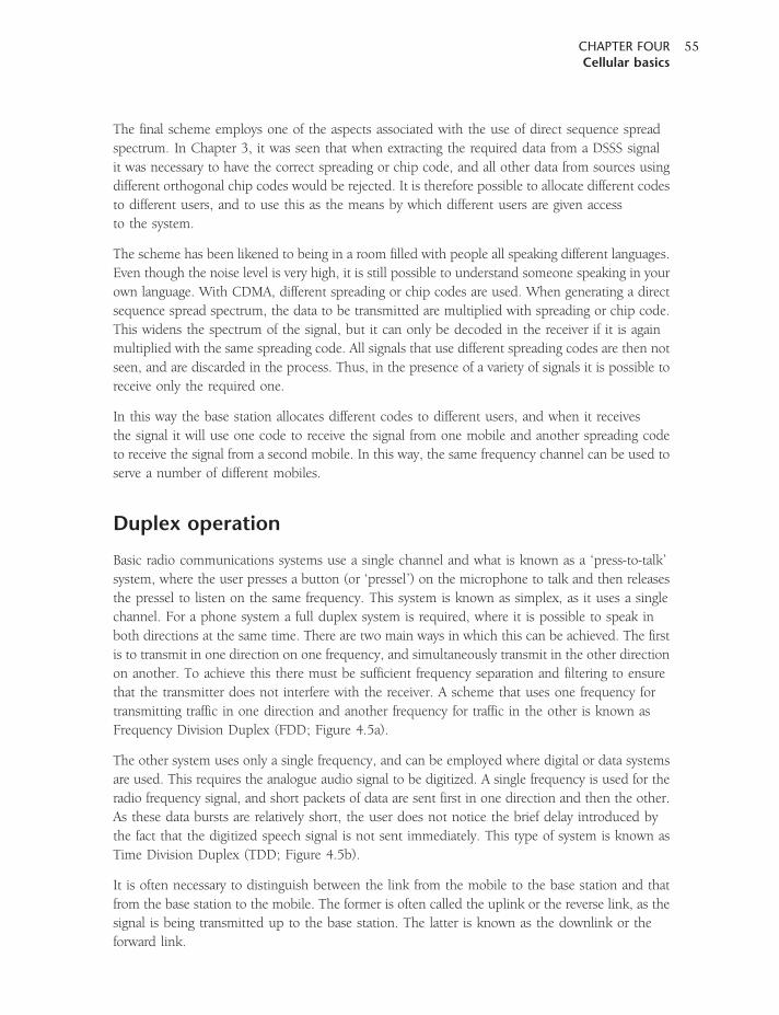
The final scheme employs one of the aspects associated with the use of direct sequence spread
spectrum. In Chapter 3, it was seen that when extracting the required data from a DSSS signal
it was necessary to have the correct spreading or chip code, and all other data from sources using
different orthogonal chip codes would be rejected. It is therefore possible to allocate different codes
to different users, and to use this as the means by which different users are given access
to the system.
The scheme has been likened to being in a room filled with people all speaking different languages.
Even though the noise level is very high, it is still possible to understand someone speaking in your
own language. With CDMA, different spreading or chip codes are used. When generating a direct
sequence spread spectrum, the data to be transmitted are multiplied with spreading or chip code.
This widens the spectrum of the signal, but it can only be decoded in the receiver if it is again
multiplied with the same spreading code. All signals that use different spreading codes are then not
seen, and are discarded in the process. Thus, in the presence of a variety of signals it is possible to
receive only the required one.
In this way the base station allocates different codes to different users, and when it receives
the signal it will use one code to receive the signal from one mobile and another spreading code
to receive the signal from a second mobile. In this way, the same frequency channel can be used to
serve a number of different mobiles.
Duplex operation
Basic radio communications systems use a single channel and what is known as a ‘press-to-talk’
system, where the user presses a button (or ‘pressel’) on the microphone to talk and then releases
the pressel to listen on the same frequency. This system is known as simplex, as it uses a single
channel. For a phone system a full duplex system is required, where it is possible to speak in
both directions at the same time. There are two main ways in which this can be achieved. The first
is to transmit in one direction on one frequency, and simultaneously transmit in the other direction
on another. To achieve this there must be sufficient frequency separation and filtering to ensure
that the transmitter does not interfere with the receiver. A scheme that uses one frequency for
transmitting traffic in one direction and another frequency for traffic in the other is known as
Frequency Division Duplex (FDD; Figure 4.5a).
The other system uses only a single frequency, and can be employed where digital or data systems
are used. This requires the analogue audio signal to be digitized. A single frequency is used for the
radio frequency signal, and short packets of data are sent first in one direction and then the other.
As these data bursts are relatively short, the user does not notice the brief delay introduced by
the fact that the digitized speech signal is not sent immediately. This type of system is known as
Time Division Duplex (TDD; Figure 4.5b).
It is often necessary to distinguish between the link from the mobile to the base station and that
from the base station to the mobile. The former is often called the uplink or the reverse link, as the
signal is being transmitted up to the base station. The latter is known as the downlink or the
forward link.
CHAPTER FOURCellular basics
55
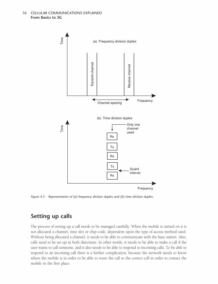
Setting up calls
The process of setting up a call needs to be managed carefully. When the mobile is turned on it is
not allocated a channel, time slot or chip code, dependent upon the type of access method used.
Without being allocated a channel, it needs to be able to communicate with the base station. Also,
calls need to be set up in both directions. In other words, it needs to be able to make a call if the
user wants to call someone, and it also needs to be able to respond to incoming calls. To be able to
respond to an incoming call there is a further complication, because the network needs to know
where the mobile is in order to be able to route the call to the correct cell in order to contact the
mobile in the first place.
Tran
smit
chan
nel
Tim
eT
ime
Rec
eive
cha
nnel
Channel spacing
(a) Frequency division duplex
(b) Time division duplex
Guardinterval
Only onechannelused
Tx
Tx
Rx
Rx
Rx
Frequency
Frequency
Figure 4.5 Representation of (a) frequency division duplex and (b) time division duplex.
CELLULAR COMMUNICATIONS EXPLAINEDFrom Basics to 3G
56
There is a variety of tasks that need to be undertaken when a phone is turned on. It actually
takes a few seconds from switching the phone on until it is ready for use. Part of this process is
registration, and there are several aspects to this. The first is to make contact with the base station,
and then the mobile has to register to allow it to have access to and use the network.
In order to make contact with the base station, the mobile uses a paging or control channel.
The name of this channel and the exact way in which it works will vary from one cellular standard
to the next, but it is a channel that the mobile can access to indicate its presence. The message
sent is often called the ‘attach’ message. Once this has been achieved, it is necessary for the mobile
to register.
There must be a register or database of users of a given network. With mobiles often being able to
access all the channels available in a country, measures to ensure that the mobile registers with the
correct network, and that the account is valid, are required. Additionally, this is required for billing
purposes. To achieve this, an entity on the network, often known as the Authentication Centre
(AuC), is used. The network and the mobile communicate, and numbers give the identity
of the subscriber. The user information is then checked to provide authentication and encryption
parameters that verify the user’s identity and ensure the confidentiality of each call, protecting users
and network operators from fraud.
Once accepted onto the network, two further registers are normally required: the Home Location
Register (HLR) and the Visitors’ Location Register (VLR). These two registers are required to keep
track of the mobile so that the network knows where it is at any time in order for calls to be routed
to the correct base station or general area of the network. These registers are used to store the last
known location of the mobile. Thus at registration the register is updated, and then periodically
the mobile updates its position. Even when the mobile is in what is termed its ‘idle mode’ it will
communicate with the network on a regular basis to update its position and status. When the
mobile is switched off, it sends a detach message. This informs the network that it is switching off,
and enables the network to update its last known position.
Two registers are required – one for mobiles for which the network is the home network (i.e. the
one with whom the contract exists) and the other for visitors. If there were only one register, then
every time the mobile sent any message to the foreign network this would need to be relayed back
to the home network, and this would require international signalling. The approach adopted is to
send a message back to the HLR when the mobile first enters the new country, saying that the
mobile is in a different network and that any calls for that mobile should be forwarded to the
foreign visited network.
Receiving and making a call
One of the key elements in the receipt of an incoming call is the use of a paging channel. Under idle
conditions, the mobile listens to the paging channel. When there is an incoming call, the network
sends out a message in the cells in the area where the mobile is known to be located. The mobile
monitors each message that is sent and compares the number with its own, responding only
when the particular mobile in question has a call for which it is the destination.
CHAPTER FOURCellular basics
57
Monitoring the paging channel all the time consumes current and this reduces battery life, although
much less than when the mobile is transmitting. Battery life is of key importance to any
mobile design, so many schemes to reduce battery drain and thereby prolong the battery life are
implemented. As a result of this, many mobile systems adopt a procedure whereby the mobile
has to listen for only part of the time.
One solution is to divide the paging messages into ten groups, depending on the last digit
of the mobile telephone number. These groups, known as paging sub-groups, are sent
in order and then repeated. This means that the mobile is required to synchronize with the
timing of the paging message, and then it only needs to have the receiver active for 10 per cent
of the time.
The drawback of the scheme is that it takes longer for calls to be routed through to the destination
mobile. When a call needs to be set up, the network has to wait until it is time to transmit
that particular paging group before it can send the paging message. This is the reason why it often
takes some time to obtain a ringing tone after a mobile has been called. While this
is a disadvantage, the gain of significantly improved battery life outweighs the drawback of the
small additional wait to set up the call.
Receiving the paging message is only the first part of the exchange, as the mobile needs to
acknowledge the call and the call needs to be set up. To achieve this, a channel that is often called
the ‘random access channel’ is used. This channel serves two purposes, one is responding to
paging messages, and the other is when the mobile needs to contact the base station to initiate
a call. Mobiles send what is termed an ‘access message’, requesting a slot or channel for
further communication.
The random access channel is given its name because mobiles access it randomly. As the network
does not know when access is required, it cannot allocate slots. It is quite possible that two or more
mobiles will access the channel at the same time, and both messages will collide. To ensure that the
message has arrived and been read the mobile waits for an acknowledgement, and if no response
is forthcoming then it waits a random amount of time before re-sending the message. By waiting
a random length of time it significantly reduces the chances of a repeat collision with the same
mobile. The chances of collisions are also reduced by keeping the messages on the random access
channel short.
Once the message has been received an acknowledgement is sent, along with details of
which channel to use. The mobile is then able to use the allocated channel to establish its
communication.
Handover and handoff
The concept of a cellular phone system is that it has a large number of base stations each covering
a small area of cells, and as a result frequencies are able to be re-used. Cell-phone systems also
provide mobility. It is therefore a very basic requirement of the system that as the mobile handset
moves out of one cell and into the next, it must be possible to hand the call over from the base
CELLULAR COMMUNICATIONS EXPLAINEDFrom Basics to 3G
58
station of the first cell to that of the second with no discernable disruption to the call. There are two
terms for this process: ‘handover’ is used within Europe, and ‘handoff’ in North America.
Although the concept of handover is relatively straightforward, it is not an easy process to
implement in reality. The system needs to decide when handover is necessary, and to which
cell, and when the handover occurs it is necessary to re-route the call to the relevant base
station while changing the communication between the mobile and the base station to
a new channel. All of this needs to be undertaken without any noticeable interruption to the call.
The process is quite complicated, and in early systems calls were often lost if the process
did not work correctly.
Different cellular standards handle handover in slightly different ways, and a considerable amount
of effort is placed on ensuring the standard defines a very robust method for handling handover,
as this is such a key element in any cellular system. For the sake of explanation, the example of
the way that GSM handles handover is given.
There are a number of parameters that need to be known to determine whether a handover is
required – the signal strength of the base station with which communication is being made, and
the signal strengths of the surrounding stations. The availability of channels also needs to be
known. The mobile is obviously best suited to monitor the strength of the base stations, but only
the network knows the status of channel availability, and the network makes the decision about
when the handover is to take place and to which channel of which cell.
Accordingly, the mobile continually monitors the signal strengths of the base stations it can receive,
including the one it is currently using, and it feeds this information back. When the strength of
the signal from the cell the mobile is using starts to fall to a level where action needs to be taken,
the network looks at the strength of the signals from other cells reported by the mobile. It then
checks for channel availability, and if one is available it notifies the new cell to reserve a channel
for the incoming mobile. When ready, the current base station passes the information for the
new channel to the mobile, which then makes the change. Once there, the mobile sends a message
on the new channel to inform the network that it has arrived. If this message is successfully sent
and received, then the network shuts down communication with the mobile on the old channel,
freeing it up for other users, and all communication takes place on the new channel.
Under some circumstances, such as when one cell is nearing its capacity, the network may decide
to hand some mobiles over to another cell they are receiving that has more capacity, and in this
way reduces the load on the cell that is running to near-capacity. Accordingly, access can be
opened to the maximum number of users. In fact, channel usage and capacity are very important
factors in the design of a cellular network.
Channel usage
One of the important factors in designing a cellular system is judging the usage that the system
will receive. In order to see the greatest financial return, network operators are under pressure
to optimize the usage of the system. However, when the system becomes over-used there are not
CHAPTER FOURCellular basics
59
sufficient channels to allow all the subscribers to gain access or, alternatively, when changing from
one cell to the next there may be no free channels and the call is then dropped. Dropping calls
is obviously not popular with subscribers, and if the levels of dropped calls rise too high then the
subscriber is likely to move to another network, thereby increasing what is called the ‘churn’ rate
(the rate at which subscribers move from one network to the next).
In order to judge the capacity requirement for a system it is necessary to look at the average time
each subscriber is likely to use the system, the number of subscribers, and what the peaks in usage
are likely to be. In general it is found that usage is high over most of the working day, rising slightly
as people return home between about 5.00 and 6.00 pm.
In order to look at the traffic that is carried by a system, a unit called an Erlang (E) is used. The idea
of analysing telephone usage was first investigated by Dr Erlang (hence the name), but the
same ideas can be used for cellular telecommunications systems; the only difference is that radio
is used as the medium to carry the signals, rather than copper wire.
In essence, 1 Erlang (E) is equivalent to one channel being used 100 per cent of the time. Thus if
100 channels are available and users are using them for 10 per cent of the time, then the capacity
required is 10 E.
The amount of phone concentration (oversubscription) can be determined with the Erlang-B
function (the Erlang blocked call function). Because the telephone network must be designed
for the worst-case load, phone usage is defined as the level that is achieved during the busiest
hour of the day.
There are ways of overcoming this. As the number of phone lines or channels increases, efficiency
(in terms of fewer blocked calls) and oversubscription will also increase. This aligns with other
similar examples, and the efficiency of all systems that use statistical multiplexing improves as the
number of channel resources increases at the multiplexer. The concentration level moves from
around 2:1 at ten subscriber phone lines to more than 3:1 at sixty user phone lines.
Infrastructure
The most obvious part of the cellular network is the base station. The antennas and the associated
equipment often located in a container below are seen dotted around the country, and especially
at the sides of highways and motorways. However, there is more to the network behind this,
as the system needs to have elements of central control and it must also link in with the
PSTN landline system to enable calls to be made to and from the wire-based phones, or between
networks.
Different cellular standards, and in some cases different network operators, use different
techniques. In fact, the early systems (and AMPS was one example) did not define the system
beyond the air interface. Despite the differences between systems, the basic concepts are very
similar. In any case, systems such as GSM have a well-defined structure, and this means that
manufacturers’ products can be standardized.
CELLULAR COMMUNICATIONS EXPLAINEDFrom Basics to 3G
60
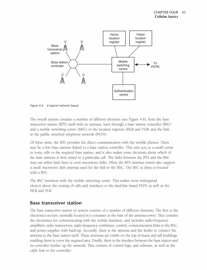
The overall system contains a number of different elements (see Figure 4.6), from the base
transceiver station (BTS) itself with its antenna, back through a base station controller (BSC)
and a mobile switching centre (MSC) to the location registers (HLR and VLR) and the link
to the public switched telephone network (PSTN).
Of these units, the BTS provides the direct communication with the mobile phones. There
may be a few base stations linked to a base station controller. This unit acts as a small centre
to route calls to the required base station, and it also makes some decisions about which of
the base stations is best suited to a particular call. The links between the BTS and the BSC
may use either land lines or even microwave links. Often the BTS antenna towers also support
a small microwave dish antenna used for the link to the BSC. The BSC is often co-located
with a BTS.
The BSC interfaces with the mobile switching centre. This makes more widespread
choices about the routing of calls and interfaces to the land-line based PSTN as well as the
HLR and VLR.
Base transceiver station
The base transceiver station or system consists of a number of different elements. The first is the
electronics section, normally located in a container at the base of the antenna tower. This contains
the electronics for communicating with the mobile handsets, and includes radio-frequency
amplifiers, radio transceivers, radio-frequency combiners, control, communication links to the BSC,
and power supplies with back-up. Secondly, there is the antenna and the feeder to connect the
antenna to the base station itself. These antennas are visible on the top of masts and tall buildings,
enabling them to cover the required area. Finally, there is the interface between the base station and
its controller further up the network. This consists of control logic and software, as well as the
cable link to the controller.
Base stationcontroller
Basetransceiver
station
Mobileswitching
centre
Homelocationregister
ToPSTN
Visitorlocationregister
Authenticationcentre
Figure 4.6 A typical network layout.
CHAPTER FOURCellular basics
61
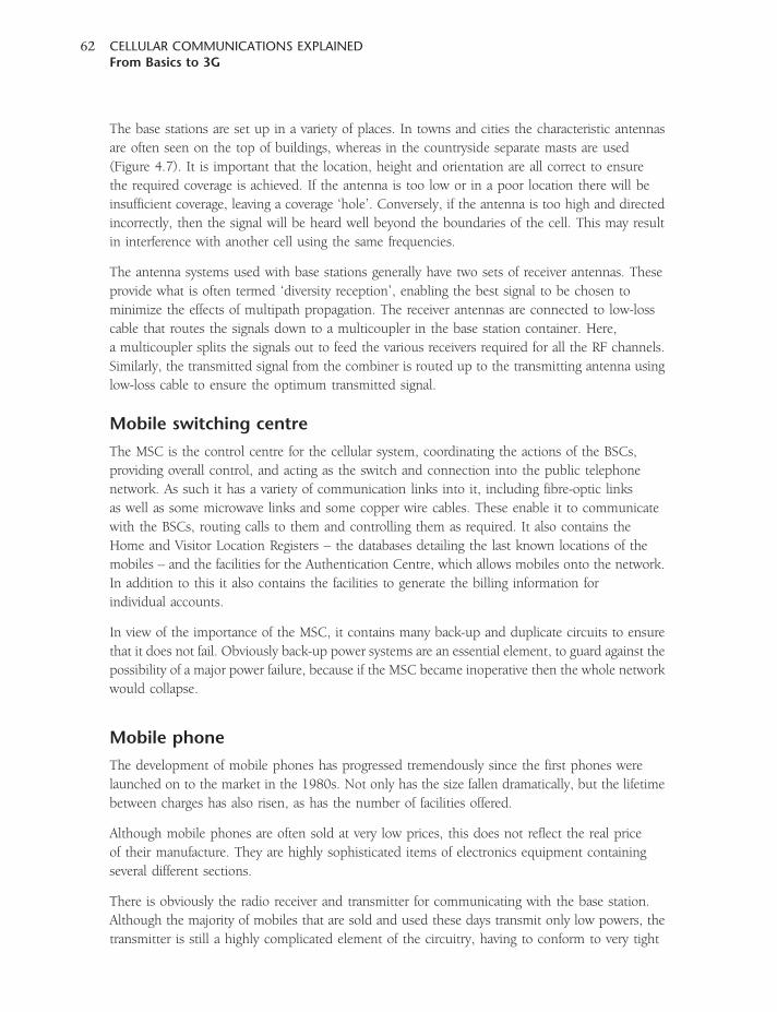
The base stations are set up in a variety of places. In towns and cities the characteristic antennas
are often seen on the top of buildings, whereas in the countryside separate masts are used
(Figure 4.7). It is important that the location, height and orientation are all correct to ensure
the required coverage is achieved. If the antenna is too low or in a poor location there will be
insufficient coverage, leaving a coverage ‘hole’. Conversely, if the antenna is too high and directed
incorrectly, then the signal will be heard well beyond the boundaries of the cell. This may result
in interference with another cell using the same frequencies.
The antenna systems used with base stations generally have two sets of receiver antennas. These
provide what is often termed ‘diversity reception’, enabling the best signal to be chosen to
minimize the effects of multipath propagation. The receiver antennas are connected to low-loss
cable that routes the signals down to a multicoupler in the base station container. Here,
a multicoupler splits the signals out to feed the various receivers required for all the RF channels.
Similarly, the transmitted signal from the combiner is routed up to the transmitting antenna using
low-loss cable to ensure the optimum transmitted signal.
Mobile switching centre
The MSC is the control centre for the cellular system, coordinating the actions of the BSCs,
providing overall control, and acting as the switch and connection into the public telephone
network. As such it has a variety of communication links into it, including fibre-optic links
as well as some microwave links and some copper wire cables. These enable it to communicate
with the BSCs, routing calls to them and controlling them as required. It also contains the
Home and Visitor Location Registers – the databases detailing the last known locations of the
mobiles – and the facilities for the Authentication Centre, which allows mobiles onto the network.
In addition to this it also contains the facilities to generate the billing information for
individual accounts.
In view of the importance of the MSC, it contains many back-up and duplicate circuits to ensure
that it does not fail. Obviously back-up power systems are an essential element, to guard against the
possibility of a major power failure, because if the MSC became inoperative then the whole network
would collapse.
Mobile phone
The development of mobile phones has progressed tremendously since the first phones were
launched on to the market in the 1980s. Not only has the size fallen dramatically, but the lifetime
between charges has also risen, as has the number of facilities offered.
Although mobile phones are often sold at very low prices, this does not reflect the real price
of their manufacture. They are highly sophisticated items of electronics equipment containing
several different sections.
There is obviously the radio receiver and transmitter for communicating with the base station.
Although the majority of mobiles that are sold and used these days transmit only low powers, the
transmitter is still a highly complicated element of the circuitry, having to conform to very tight
CELLULAR COMMUNICATIONS EXPLAINEDFrom Basics to 3G
62
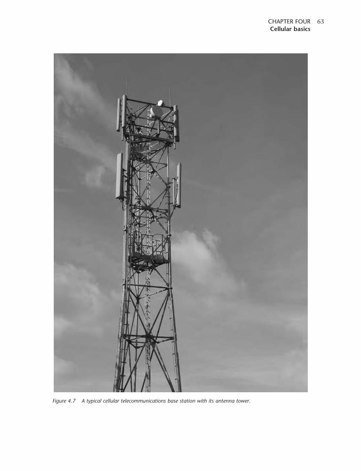
Figure 4.7 A typical cellular telecommunications base station with its antenna tower.
CHAPTER FOURCellular basics
63
limits for the level of spurious transmissions emitted. The transmitter power is dependent upon
the system in use and the type of handset, but generally powers of only a few hundred milliwatts
are transmitted. Even this may vary, as systems usually limit the power to what is actually required.
In this way, interference levels are reduced and battery power is conserved. However, tight limits
are sometimes placed on the power control tolerances, as in the case of GSM.
The choice of power amplifier mode of operation depends upon the system in use. Some systems
do not require the use of a linear power amplifier, whereas others (like those using CDMA)
need a relatively linear power amplifier. As linear power amplifiers are inherently less efficient
than non-linear ones, there can be an issue with battery life.
The receiver is also of great importance. It must be sufficiently sensitive to enable it to operate
under low signal conditions, but it must also be immune to the effects of other signals nearby –
for example, when two mobile phones are operating close together. If the receiver were sensitive to
strong off-channel signals, then its sensitivity could be significantly degraded when operating close
to another mobile. This would clearly be unacceptable. Again, with the receiver battery drain is
important. Not only must it have a low level of power consumption, but most receivers also have
an idle state when they periodically monitor channels to check for paging information. By turning
off the majority of the receiver, the drain on the battery can be reduced.
The antenna is another significant item. Today many antennas are contained within the body
of the phone, although a number of phones do have small antenna positions. In either case,
the size of the antenna has to be limited and this places significant constraints on the design.
In addition to this, the antenna must be capable of operating in the proximity of nearby objects.
Not only is the phone itself nearby, but the hand of the person using the phone may also be
shrouding it. In all cases, the antenna design must be able to operate adequately under
these conditions.
There is a significant level of control circuitry within a phone. This undertakes a large number
of tasks. It obviously controls the transmitter and receiver, setting them to the right channels as
instructed by the network. It also controls the changeover from transmit to receive. In addition
to this it will put various sections of the circuitry into a sleep mode when they are not required,
to limit the current drain on the battery and conserve power.
Any communication with the network has to be in the correct format. Data sent to and from
the base station need to be correctly formatted. There is also a large number of protocol messages
that are sent to ensure that the network and mobile operate correctly together. Messages such
as attach, detach, those sent when initiating and completing a call, when handing over to another
base station, and many more all need to be correctly controlled, and this is done by the
control circuitry.
The man–machine interface (MMI), consisting of the keypad and display, also needs to be managed
so that the user can operate the phone. This too is undertaken by the control circuitry. However,
the MMI also provides many other functions, including the phone book, text message organization,
games, clock, and many more of the applications that are finding their way into modern
mobile phones.
CELLULAR COMMUNICATIONS EXPLAINEDFrom Basics to 3G
64
Another part of many phones these days is what is called the SIM card on GSM phones. It is called
the USIM (Universal Subscriber Identity Module) for UMTS and the RUIM (Removable User
Identity Module) on CDMA phones.
The battery is a major element of the phone. Its power capacity governs the time for which the
phone can operate between charges. In recent years, battery technology has improved considerably.
Initially nickel cadmium power sources were used, which can be detrimental to the environment
if disposed of incorrectly. The next source was the nickel metal hydrogen battery, which provided
virtually the same cell voltage as the NiCad battery but with a slight improvement in performance.
Most of all, these cells did not contain the harmful cadmium constituent. The next development
of cell technology came with the introduction of the lithium ion (or Li-ion) battery. This offers
a high voltage of around 3 volts per cell, and also a greatly increased power density. This enables
the cells to be made much smaller while providing a similar or possibly larger capacity. In the
future, it is likely that fuel cells may be used. Rather than having to recharge them, these cells
require re-fuelling. With the varieties likely to be used in cell phones running on methanol
or ethanol, the refills will be cheap and easy to use.
Voice coding
All the second- and third-generation mobile phone systems use digital techniques in various
forms to transmit the voice signals of a phone call. This requires that the analogue voice signals
have to be converted to a digital format.
The conversion into a digital format is accomplished using an analogue-to-digital converter (ADC).
The ADC samples the waveform at fixed time intervals, and generates a binary representation of the
value of the waveform at that instant. The actual voice quality is dependent upon two basic factors,
namely the sampling rate and the number of bits in each sample.
It is possible to determine the minimum sampling rate from Nyquist’s theorem. This states that
the sampling rate must be twice the maximum frequency of the waveform. If a straight conversion
were used, then the amount of data required to be sent would be too high to be accommodated
in a cellular phone channel. If the maximum frequency of the audio were 4 kHz, this would require
a sampling rate of 8 kHz, and if there were 8 bits per sample, then it would require a data rate
of 64 kbps.
To overcome this problem, vocoders are used. These are able to analyse and compact the data
representing the speech so that it requires a considerably lower data rate. Typically, data rates below
15 kHz are attainable. To achieve this level of performance they use complex algorithms to analyse
the speech, and the speech is then reconstituted at the receiving end.
A variety of different vocoders is used, many of which use a technique known as Code Excited
Linear Prediction (CELP). The choice is dependent upon the cellular standard in use and,
in some instances, the conditions. However, they all give significant improvements in the data rate
and bandwidth required to transmit the signals.
CHAPTER FOURCellular basics
65
Digital data structures
With cellular systems focusing on digital technology these days, the data that are transmitted have
to be carefully organized. In this way the receiver, whether in a mobile handset or a base station,
knows what the data being received relate to, and can thus handle them accordingly.
Typically, data are organized into three elements for TDMA systems. These are frames, slots
and channels, and they follow this hierarchy. The channels should not be confused with the
radio-frequency channels that are used; they are in effect data channels that are contained
within the overall data stream.
A frame is what may be termed an all-inclusive data package. It is made up of a number of slots
which are in a given order, and the overall structure is repeated after a given time. Thus the frame
carries control information indicating features about the frame, its length etc; it also carries the
payload (typically this will be data contained within the slots), and error-checking information.
There may be start bits as well for synchronization.
The slots contain individual information destined for or arriving from a particular mobile, and are
a result of the fact that different users are allocated different time slots. A given user is allocated
a particular time slot, and in this way the relevant data can be inserted into or extracted from
the right time slot.
The next level down the hierarchy consists of the channels. These handle call-processing elements,
and are the sections of data required for particular purposes. For example, channels may be used
for actions including paging, call initiation, control, traffic data and the like.
Within CDMA systems that are not time-multiplexed, slots are not used; instead, the different
channels are made up by using different spreading codes on the same radio-frequency carrier.
In this way, the different functions, types of data and users can be separated from one another.
CELLULAR COMMUNICATIONS EXPLAINEDFrom Basics to 3G
66
5CHAPTER FIVE
Analogue systems
The first mobile phone systems to be launched were based on analogue technology. By today’s
standards the performance was limited, the phones were large, and initially the coverage was
poor. In addition to this, when the phone systems were first launched they were very expensive,
which limited them to business use. Nevertheless, these phone systems marked a major milestone
in telecommunications history. For their day they represented a major step forward in technology,
and they also established a market that grew well beyond the initial predictions. In fact, many
of these systems quickly ran out of capacity as a result of the demand as the numbers of
subscribers grew.
Around the world a number of different standards were introduced. Although many of the
systems were adapted from others, it still meant that incompatible systems were often in use
from one country to the next. As roaming was not a concept that had gained a foothold by this
time this was not a major problem, but it did mean that manufacturers could not gain
the full benefits of scale that might otherwise have been possible, even though many of the
differences were relatively small.
The three main systems that were launched were NMT (Nordic Mobile Telephone),
AMPS (Advanced Mobile Phone System, also known under its specification number as IS-41)
and TACS (Total Access Communications System). The NMT system was developed as a joint
venture by Nordic countries with Ericsson, and Nokia playing a major part, although there were
many other interested parties. This system was obviously used in Nordic countries, but was also
employed elsewhere around the world. AMPS was focused on North America, but was also
widely used around the globe. Similarly TACS, developed by Motorola, was used in the UK
as well as many other countries.
All these systems used FM for the voice channel. The channel spacing for AMPS was 30 kHz,
for TACS it was 25 kHz and for NMT it was 25 kHz. A further system, known as NAMPS or
Narrowband AMPS, was also introduced with the aim of conserving spectrum, but this did not
gain widespread acceptance because the first digital systems were in the process of being
developed by this time. In general the systems used frequencies in the region of 900MHz,
although the NMT system made use of an allocation around 450MHz.
The major analogue mobile phone systems are summarized in Table 5.1.
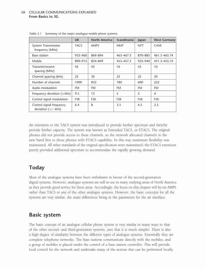
An extension to the TACS system was introduced to provide further spectrum and thereby
provide further capacity. The system was known as Extended TACS, or ETACS. The original
phones did not provide access to these channels, so the network allocated channels in the
new band first to those phones with ETACS capability. In this way maximum flexibility was
maintained. All other standards of the original specification were maintained; the ETACS extension
purely provided additional spectrum to accommodate the rapidly growing demand.
Today
Most of the analogue systems have been withdrawn in favour of the second-generation
digital systems. However, analogue systems are still in use in many outlying areas of North America
as they provide good service for these areas. Accordingly, the focus on this chapter will be on AMPS
rather than TACS or any of the other analogue systems. However, the basic concepts for all the
systems are very similar, the main differences being in the parameters for the air interface.
Basic system
The basic concept of an analogue cellular phone system is very similar in many ways to that
of the other second- and third-generation systems, save that it is much simpler. There is also
a high degree of similarity between the different types of analogue systems. Essentially they are
complete telephone networks. The base stations communicate directly with the mobiles, and
a group of mobiles is placed under the control of a base station controller. This will provide
local control for the network and undertake many of the actions that can be performed locally.
Table 5.1 Summary of the major analogue mobile phone systems.
UK North America Scandinavia Japan West Germany
System Transmission
frequency (MHz)
TACS AMPS NMT NTT C450
Base station 935–960 869–894 463–467.5 870–885 461.3–465.74
Mobile 890–915 824–849 453–457.5 925–940 451.3–455.74
Transmit/receive
spacing (MHz)
45 45 10 55 10
Channel spacing (kHz) 25 30 25 25 20
Number of channels 1000 832 180 600 222
Audio modulation FM FM FM FM FM
Frequency deviation (� kHz) 9.5 12 5 5 4
Control signal modulation FSK FSK FSK FSK FSK
Control signal frequency
deviation (þ/�kHz)
6.4 8 3.5 4.5 2.5
CELLULAR COMMUNICATIONS EXPLAINEDFrom Basics to 3G
68
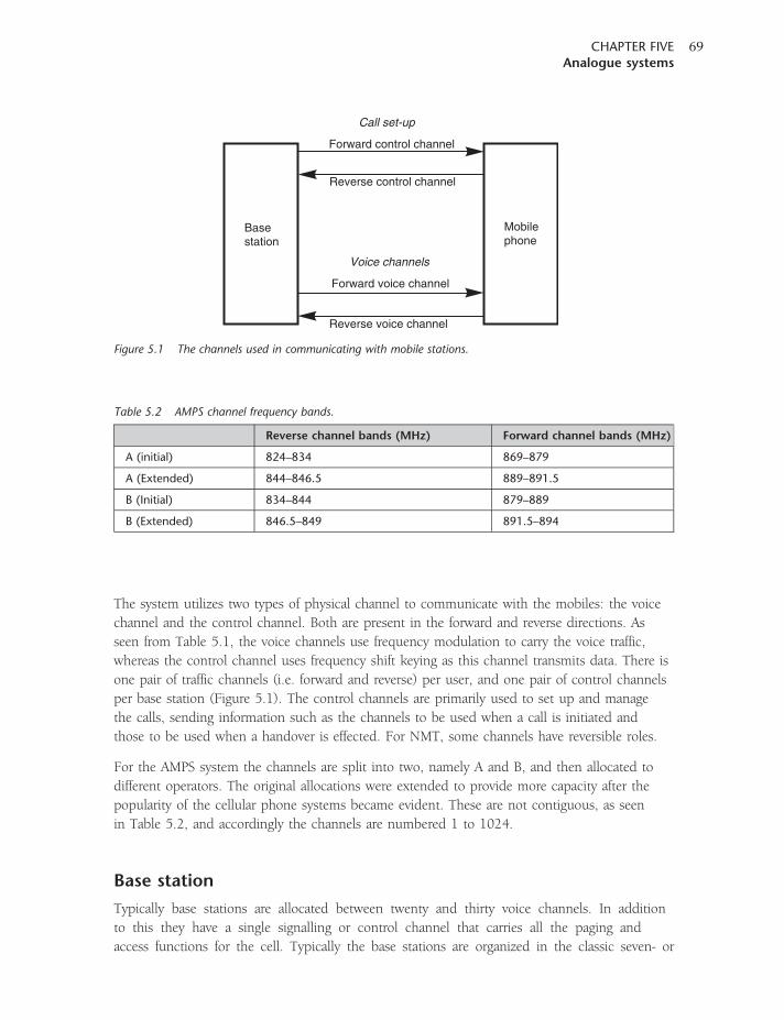
The system utilizes two types of physical channel to communicate with the mobiles: the voice
channel and the control channel. Both are present in the forward and reverse directions. As
seen from Table 5.1, the voice channels use frequency modulation to carry the voice traffic,
whereas the control channel uses frequency shift keying as this channel transmits data. There is
one pair of traffic channels (i.e. forward and reverse) per user, and one pair of control channels
per base station (Figure 5.1). The control channels are primarily used to set up and manage
the calls, sending information such as the channels to be used when a call is initiated and
those to be used when a handover is effected. For NMT, some channels have reversible roles.
For the AMPS system the channels are split into two, namely A and B, and then allocated to
different operators. The original allocations were extended to provide more capacity after the
popularity of the cellular phone systems became evident. These are not contiguous, as seen
in Table 5.2, and accordingly the channels are numbered 1 to 1024.
Base station
Typically base stations are allocated between twenty and thirty voice channels. In addition
to this they have a single signalling or control channel that carries all the paging and
access functions for the cell. Typically the base stations are organized in the classic seven- or
Forward control channel
Forward voice channel
Call set-up
Voice channels
Reverse control channel
Reverse voice channel
Mobilephone
Basestation
Figure 5.1 The channels used in communicating with mobile stations.
Table 5.2 AMPS channel frequency bands.
Reverse channel bands (MHz) Forward channel bands (MHz)
A (initial) 824–834 869–879
A (Extended) 844–846.5 889–891.5
B (Initial) 834–844 879–889
B (Extended) 846.5–849 891.5–894
CHAPTER FIVEAnalogue systems
69
twelve-cell arrangement to provide adequate channel re-use, while still maintaining sufficient
levels of separation to ensure that interference levels are reduced to satisfactory figures. In
some urban areas where system usage is very high the cell coverage areas are reduced, and
the cells may be arranged in a four-cell repeat pattern with six sectors to a cell. Each of the
sectors is then allocated its own set of voice channels, although a single signalling channel is
retained for the whole base station.
The voice channels and signalling channel outputs are combined using a high Q cavity resonator.
As the system operates in full duplex and the transmission mode is FM for the voice channels and
FSK for the paging or control channel, this is on all the time. The output from the combiner is fed
to the antennas. Often these are of the collinear variety, providing around 9 dB gain over a dipole.
The radiation is omni-directional to provide coverage all around the cell. In some instances, the
directional pattern may be altered to ensure that interference between cells using the same channels
is reduced to the minimum.
For receiving, many base stations are fitted with six directional antennas. These have considerably
more gain than the transmitting antenna, and they are often mounted at 60� angles. The outputs
from these antennas are then switched so that the optimum signal can be chosen for the receiver.
To ensure that the receiver is always provided with the best signal, a scanning receiver is used.
This monitors every channel on the base station on every antenna every few seconds, and
ensures that the best signal is routed through to the relevant receiver for each channel. In this
way, the optimum reception is maintained.
The use of multiple antennas with additional gain for receiving while maintaining an
omni-directional transmit pattern has several advantages. The base station is able to transmit
a higher power level than the mobile, and therefore antenna gain is less important. However,
for receiving, the fact that the mobile is able to transmit only a lower power can be compensated
for at the base station by having a high-gain antenna. The gain in the antenna means that it will
be directional, and this is overcome by having a set of antennas with the scanning receiver.
The network and base station are provided with identification codes. In the USA, the System
Identifier (SID) is assigned by the Federal Communications Commission (FCC) along with the
carrier frequencies for each geographical area. The system identifier is used by the mobile to ensure
that it is on the correct network.
Mobile switching centres
In a network there may typically be around twenty mobile switching centres. These mobile
switching centres (MSC) or, as they are sometimes called in AMPS, Mobile Telephone
Switching Offices (MTSO), are effectively a digital exchange, and they have a distributed
architecture. To achieve this, the switching centres are linked together to provide a fully
integrated network. Also, the base station controllers are linked to the most convenient MSC,
often by a dedicated line, although other links are used as appropriate. The base station
controllers typically control a small number of individual base stations and are linked either
by a wire landline or, often, a short-range microwave link.
CELLULAR COMMUNICATIONS EXPLAINEDFrom Basics to 3G
70
Mobile equipment
By today’s standards, the mobile phones used for analogue systems were large and offered
a lower level of performance. Battery life was much shorter. This was a result of the fact that
semiconductor technology was less advanced, and frequency modulation was used. This
requires that the full power be transmitted all the time that a call is in process (one of
the advantages of the TDMA technology used for the second-generation GSM and
NA-TDMA technologies is that the duty cycle during a call is only 12.5 per cent).
Furthermore, both transmit and receive functions are required during a call and this means
that the two frequency synthesizers used as the local oscillators are required – one for the
transmit side of the phone and the other for the receive side. This again increased
battery consumption.
Mobiles are given a Mobile Identifier Number (MIN). This is equivalent to a land-line
telephone number, and includes an area code identifying the home service area, a three-digit
exchange number and a four-digit subscriber identification number. This number is used
in a variety of areas, not least of which is to route calls through to the mobile phone.
The mobile also has what is termed an electronic serial number (ESN). This code is permanently
assigned at manufacture and acts as a security number, helping to prevent fraud – particularly
in the form of phone cloning. The code is 32 bits long, and consists of three fields. These include
an 8-bit manufacturer code, an 18-bit serial number and 6 bits reserved for future use. Many
manufacturers have tried to implement a feature that renders the phone inoperative if there is
any attempt to alter the ESN.
A further identifier within the phone is able to inform the network of the capabilities of the
phone. Parameters such as the number of channels it can support, the power output class and
the like can be passed to the network.
Voice messaging
The voice is carried on the main ‘traffic’ channel, one of which is allocated to each mobile making
a call. The audio is modulated onto the carrier using FM, which causes the carrier to deviate in
line with the instantaneous level of the modulation. The actual level of deviation varies between
the different systems, but for AMPS the maximum deviation is �12 kHz, whereas for TACS
it was 9.5 kHz.
The audio is processed to ensure that the carrier signal is used as effectively as possible. It is
found that speech consists of short high peaks, with longer periods of low intensity. This is
fine when listening to someone talking face to face, but for an electronic medium such as
a mobile phone it leads to considerable inefficiency. If not processed, the system would have to
be set to enable it to cater for the high peak levels, but this would mean that the average level
of deviation was very low and thus the speech would become very susceptible to any noise present.
It was found that if the average level of the speech could be raised, it would be much easier
to hear and less susceptible to noise.
CHAPTER FIVEAnalogue systems
71
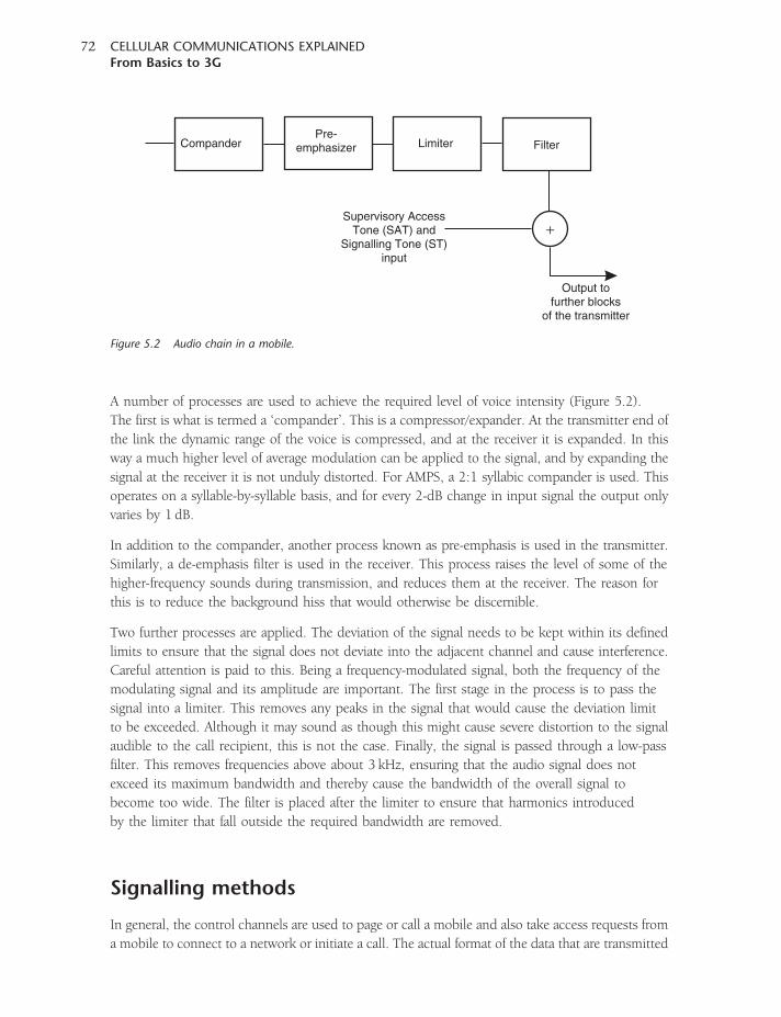
A number of processes are used to achieve the required level of voice intensity (Figure 5.2).
The first is what is termed a ‘compander’. This is a compressor/expander. At the transmitter end of
the link the dynamic range of the voice is compressed, and at the receiver it is expanded. In this
way a much higher level of average modulation can be applied to the signal, and by expanding the
signal at the receiver it is not unduly distorted. For AMPS, a 2:1 syllabic compander is used. This
operates on a syllable-by-syllable basis, and for every 2-dB change in input signal the output only
varies by 1 dB.
In addition to the compander, another process known as pre-emphasis is used in the transmitter.
Similarly, a de-emphasis filter is used in the receiver. This process raises the level of some of the
higher-frequency sounds during transmission, and reduces them at the receiver. The reason for
this is to reduce the background hiss that would otherwise be discernible.
Two further processes are applied. The deviation of the signal needs to be kept within its defined
limits to ensure that the signal does not deviate into the adjacent channel and cause interference.
Careful attention is paid to this. Being a frequency-modulated signal, both the frequency of the
modulating signal and its amplitude are important. The first stage in the process is to pass the
signal into a limiter. This removes any peaks in the signal that would cause the deviation limit
to be exceeded. Although it may sound as though this might cause severe distortion to the signal
audible to the call recipient, this is not the case. Finally, the signal is passed through a low-pass
filter. This removes frequencies above about 3 kHz, ensuring that the audio signal does not
exceed its maximum bandwidth and thereby cause the bandwidth of the overall signal to
become too wide. The filter is placed after the limiter to ensure that harmonics introduced
by the limiter that fall outside the required bandwidth are removed.
Signalling methods
In general, the control channels are used to page or call a mobile and also take access requests from
a mobile to connect to a network or initiate a call. The actual format of the data that are transmitted
CompanderPre-
emphasizer Limiter
Output tofurther blocks
of the transmitter
Filter
Supervisory AccessTone (SAT) and
Signalling Tone (ST)input
+
Figure 5.2 Audio chain in a mobile.
CELLULAR COMMUNICATIONS EXPLAINEDFrom Basics to 3G
72
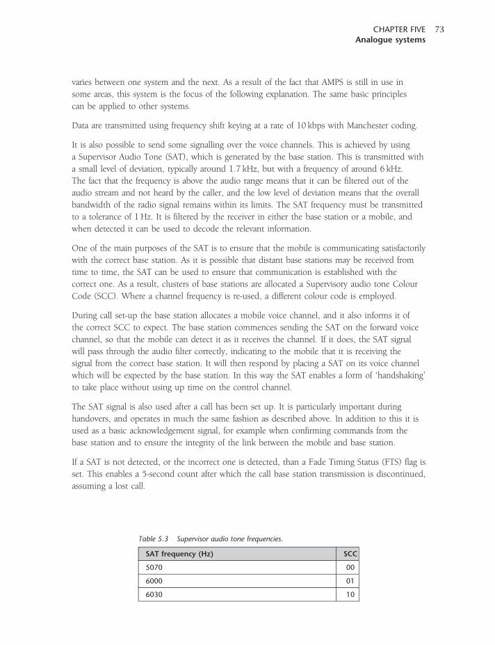
varies between one system and the next. As a result of the fact that AMPS is still in use in
some areas, this system is the focus of the following explanation. The same basic principles
can be applied to other systems.
Data are transmitted using frequency shift keying at a rate of 10 kbps with Manchester coding.
It is also possible to send some signalling over the voice channels. This is achieved by using
a Supervisor Audio Tone (SAT), which is generated by the base station. This is transmitted with
a small level of deviation, typically around 1.7 kHz, but with a frequency of around 6 kHz.
The fact that the frequency is above the audio range means that it can be filtered out of the
audio stream and not heard by the caller, and the low level of deviation means that the overall
bandwidth of the radio signal remains within its limits. The SAT frequency must be transmitted
to a tolerance of 1 Hz. It is filtered by the receiver in either the base station or a mobile, and
when detected it can be used to decode the relevant information.
One of the main purposes of the SAT is to ensure that the mobile is communicating satisfactorily
with the correct base station. As it is possible that distant base stations may be received from
time to time, the SAT can be used to ensure that communication is established with the
correct one. As a result, clusters of base stations are allocated a Supervisory audio tone Colour
Code (SCC). Where a channel frequency is re-used, a different colour code is employed.
During call set-up the base station allocates a mobile voice channel, and it also informs it of
the correct SCC to expect. The base station commences sending the SAT on the forward voice
channel, so that the mobile can detect it as it receives the channel. If it does, the SAT signal
will pass through the audio filter correctly, indicating to the mobile that it is receiving the
signal from the correct base station. It will then respond by placing a SAT on its voice channel
which will be expected by the base station. In this way the SAT enables a form of ‘handshaking’
to take place without using up time on the control channel.
The SAT signal is also used after a call has been set up. It is particularly important during
handovers, and operates in much the same fashion as described above. In addition to this it is
used as a basic acknowledgement signal, for example when confirming commands from the
base station and to ensure the integrity of the link between the mobile and base station.
If a SAT is not detected, or the incorrect one is detected, than a Fade Timing Status (FTS) flag is
set. This enables a 5-second count after which the call base station transmission is discontinued,
assuming a lost call.
Table 5.3 Supervisor audio tone frequencies.
SAT frequency (Hz) SCC
5070 00
6000 01
6030 10
CHAPTER FIVEAnalogue systems
73
A further tone, known as the Signalling Tone (ST), is used in AMPS. Unlike the SAT, which is
generated by the base station and then relayed back by the handset, the ST is actually generated
within the handset and has a frequency of 10 kHz. Thus tone is used in combination with the
SAT to provide an indicator of a variety of states during the course of a call. It is also used as
an ‘acknowledge’ signal in some instances.
Control channels
The control channels are the means by which the radio elements of the cellular system are
organized. As such the control channels are of prime importance, maintaining order within
the radio channels and informing the mobiles which channels they need to use.
For AMPS, there is a total of twenty-one channels that are reserved in each direction. One control
channel is assigned to each base station, and mobiles can search for the strongest control channel
to assess the best base station to access.
There are two types of control channel: forward and reverse. For AMPS, the forward channel is
known as the FOrward Control Channel (FOCC) and the other as the REverse Control Channel
(RECC).
Forward control channel
The FOCC is transmitted continuously by the base station so that it can be received by all
mobiles. It also acts as a beacon for mobiles joining the network, and for others looking for
alternative base stations in case they need to handover from one base station to the next.
With a total of twenty-one control channels available, mobiles scan these frequencies to look for
the strongest signal, as the one with the strongest control channel is likely to provide the
best overall communications.
It is interesting to note that not only can the antenna patterns be altered to change the coverage area
of the base station, but also adjustment of the power of the control channel has a similar effect.
If the power is reduced then the range of the signal is reduced, and mobiles in a more restricted
area will find it as the strongest signal. Similarly, the receive sensitivity and thresholds need to be
altered so that the transmitter and receiver are compatible.
The control channel obviously performs other functions as well. It transmits control data to the
mobiles so that they can act in accordance with the wishes of the network. Data is transmitted
at 10 kbps, and it consists of frames of 463 bits which take 46.3ms to transmit.
The data stream is made up from several components. It starts with synchronization or sync bits,
after which there are two words. Each of these words is repeated five times in a frame. The words
are addressed to different mobiles. Mobiles with even MINs refer to word A, and those with odd
MINS refer to word B. In addition to this there are busy/idle bits. These are sent every 10 bits, and
are used to control the access of the mobile to the system.
CELLULAR COMMUNICATIONS EXPLAINEDFrom Basics to 3G
74

Reverse control channel
The RECC uses a 48-bit word which is repeated five times, making a 240-bit sequence. The
mobiles transmit on the channel only when instructed to do so, or when accessing the system.
As a result, there may be times when it appears to be unoccupied.
There are three main messages that are carried by the RECC, and these are registration, origination
and page response. The registration message is sent by the mobile before any calls are set up.
The mobile needs to be accepted onto the network prior to either receiving or sending any calls.
Origination messages are also required. These are sent when a number is dialled and the mobile
communicates this with the network. Finally, responses are required when a mobile is paged to
say that there is an incoming call.
Call initiation
In order to make a call from a mobile phone, the phone has to originate the call and communicate
its intention to make a call. The phone knows the correct channel to use from information
broadcast on the FOCC, and transmits a request on the channel.
As the system does not have access to the network, it cannot ask for a slot in which to transmit so
it will not interfere with other mobiles. Accordingly, it uses a technique known as Carrier Sense
Multiple Access (CSMA). Using this scheme, the mobile phone sends its message and waits for
an acknowledgement. If it does not receive an acknowledgement, it assumes that another mobile
is transmitting and has blocked its message. It waits until the other mobile should have stopped
transmitting and tries to send its message again, repeating this until it receives a response.
The message from the mobile contains information about it, including its MIN and ESN.
After transmitting the message, it listens on the FOCC for the acknowledgement and channel
assignment. The base station forwards the request to the Mobile Switching Centre and, after
validating the mobile, selects a traffic channel pair for the mobile. If no channels are available,
the network rejects the request.
If the network allows the mobile onto the network, it allocates the channels and sends this
information to the mobile, which then retunes its transmitter and receiver accordingly, and the
SAT is used to confirm that all is set correctly. Additionally the network routes the call to the
PSTN, where it is further routed through to the destination, or to another mobile on the network.
All call and power control from this point forward is handled using SAT and ST on the
AMPS traffic channel assigned to the mobile.
Paging and incoming call set-up
When an AMPS mobile is not engaged in a call, it monitors the FOCC for any paging calls that may
occur. The phone checks the correct data words in the data frames sent out on the paging channel.
CHAPTER FIVEAnalogue systems
75
As explained previously, mobiles with even MINs listen to one of the data words, and those with
odd MINs listen to the other.
When a call attempt is directed to the mobile, the paging signal is set more than once. It is actually
repeated after several seconds in case the mobile was temporarily in an RF ‘hole’ or otherwise
unable to receive the first page. The time interval between pages is short to minimize the
ringing delay experienced by the originator of the call.
Once received, the mobile responds to the page using the RECC. It then awaits the network
assigning it a pair of traffic channels. The mobile response is also repeated, in case the initial
response collided with another mobile on the reverse control channel or the message does not
succeed as a result of a poor signal path or interference.
Once the mobile has received details of the channels that are assigned to it, it proceeds to
these channels. At the same time, the network produces the audible ringing tone and the
phone starts to ring. As in the case of a mobile-originated call, all further signalling takes place
using the tones on the voice or traffic channel.
Handoff
During the course of a call it is quite likely that the mobile will change its location, and the
signal strengths between the mobile and the base station and the base station and the mobile
will fall as the mobile moves away from the base station. During the call the scanning receiver
monitors the quality of the received signal in terms of what is essentially a signal-to-noise ratio.
If this measurement falls below a predetermined level, the base station sends a message to the
mobile switching centre to advise of the situation.
The system them initiates a search for a more suitable cell by requesting the adjacent cells
to measure the strength of the signal of the relevant mobile.
If the signal is received better in another base station, a new channel on that station is allocated
if one is available. A second voice path is then set up and bridged across to the existing one in
preparation for the handoff.
Once this is complete, the system or network generates a handoff instruction and sends it over
the FOCC. This carries information that includes the new channel to be used along with the
SAT. The mobile accepts the information and sends an ST signalling tone for 50ms. It then
turns off the reverse channel transmission and retunes to the new channel. The transmitter in
the mobile is turned off so that the signal does not sweep across all the other channels in between,
causing interference.
Once it reaches the new channel, the mobile turns its voice transmitter channel transmission
on and retransmits the SAT of the new base station. This acts as confirmation that the new link
has been established. Accordingly, when the new base station receives this it informs the
mobile switching centre that the handoff has been successfully accomplished. It then informs
CELLULAR COMMUNICATIONS EXPLAINEDFrom Basics to 3G
76
the old base station to release the channel the mobile was previously using, making it available
for further use.
Summary
The analogue systems were a major technological achievement for their time, and in addition to
this they also established a market that grew very much faster than expected. However, there were
several drawbacks to the system that were soon discovered. With the rapidly growing number of
subscribers, capacity started to become a major issue. This was why the FCC in the USA, and
the equivalent in governments around the world, started to allocate further spectra. In the UK,
the TACS system was extended as ETACS to provide further capacity. However, it was obvious
that new technology would be needed to overcome the problem in the long term.
Another problem was that of security. Not only was it possible to listen in to conversations,
but in addition to this it was possible to clone phones very easily.
As a result of these problems, new systems were developed to ensure that capacity and quality
of service targets could be met, and security levels significantly improved. The resulting systems
used digital technology and resulted in the migration from the first-generation analogue systems
to the second-generation digital ones.
CHAPTER FIVEAnalogue systems
77

6CHAPTER SIX
GSM
The system now referred to as GSM started life as the Groupe Speciale Mobile. Later this was
changed to represent its global nature, while keeping the same initials, to Global System for Mobile
communications.
The aim was an initiative to develop a digital mobile phone system that would support roaming
across country borders and also provide improved capacity when compared to the analogue
systems that were then in use. As the press had made much of the lack of security of some of the
analogue systems that had been in use, with more than one high-ranking dignitary having their calls
listened to by outsiders, call privacy and security were also high on the agenda.
The goals set for the system were tough, as no digital system had been launched before and
neither had any attempts at roaming on this scale been considered. The original aim was to use
spectra in the 900-MHz region, but since its initial launch further bands have been used at 1800,
1900 and, more recently, 800MHz. Originally the systems using the high-frequency bands were
given the names DCS 1800 (Digital Communications System) and PCS 1900 (Personal
Communications System). Now they are simply referred to as GSM 1800 and GSM 1900
respectively.
The system has been a considerable success, far outstripping the take-up by any other network
beforehand or currently available. In early 2004 the system had over a billion subscribers, and this
figure has continued to rise.
Part of the success of the GSM system is that the standard has rigorously defined the whole system.
The standard was generated and controlled under the auspices of ETSI. In this way a truly
international standard was generated, and all manufacturers and service providers have to adhere to
the standard. In this way, not only did global roaming become a reality; it also meant that
manufacturers could cater for a global market and benefit from economies of scale. These benefits
of cost could also be passed on to the consumer, making it a very attractive solution. Previously
there had been a large variety of different systems, and manufacturers had to tailor their solutions to
the relevant countries and systems. Even now the other systems in use around the world are not
standardized to the same degree, and this prevents seamless roaming across countries and even
different networks within the same country. The running of the GSM standard has now been
passed to 3GPP, the organization that is also controlling the third generation UMTS (Universal
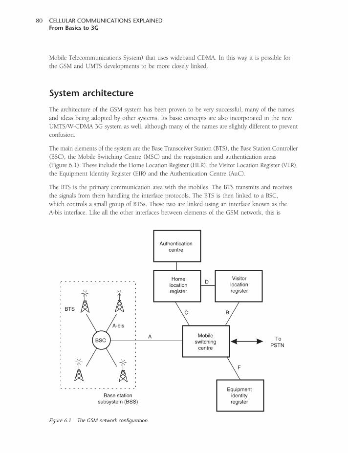
Mobile Telecommunications System) that uses wideband CDMA. In this way it is possible for
the GSM and UMTS developments to be more closely linked.
System architecture
The architecture of the GSM system has been proven to be very successful, many of the names
and ideas being adopted by other systems. Its basic concepts are also incorporated in the new
UMTS/W-CDMA 3G system as well, although many of the names are slightly different to prevent
confusion.
The main elements of the system are the Base Transceiver Station (BTS), the Base Station Controller
(BSC), the Mobile Switching Centre (MSC) and the registration and authentication areas
(Figure 6.1). These include the Home Location Register (HLR), the Visitor Location Register (VLR),
the Equipment Identity Register (EIR) and the Authentication Centre (AuC).
The BTS is the primary communication area with the mobiles. The BTS transmits and receives
the signals from them handling the interface protocols. The BTS is then linked to a BSC,
which controls a small group of BTSs. These two are linked using an interface known as the
A-bis interface. Like all the other interfaces between elements of the GSM network, this is
BSC
BTS
A-bis
A
C
D
B
F
Base stationsubsystem (BSS)
Mobileswitching
centre
Homelocationregister
ToPSTN
Visitorlocationregister
Authenticationcentre
Equipmentidentityregister
Figure 6.1 The GSM network configuration.
CELLULAR COMMUNICATIONS EXPLAINEDFrom Basics to 3G
80
now rigorously defined to enable equipment from different manufacturers to be used together.
However, some of this standardization came late, and it means that many older components
are proprietary makes, enabling only BSCs and BTSs from particular manufacturers to be
connected.
The BSC manages one or more BTSs. It handles the radio channel set-up, frequency hopping
control and handovers. It links with the MSC or mobile switching centre via an interface termed
the A interface. A further task normally handled by the BSC is to translate the 13-kbps voice data
rate used over the radio link to the standard 64 kbps used by the PSTN.
The core of the network sub-system is the MSC, or mobile switching centre, acting like a
switching node of the PSTN. In addition to this it interfaces with the AuC to provide authentication
allowing users onto the network. It also interfaces with the HLR and VLR to provide location
information for the network, so that calls can be routed to the correct BTS – including those that
may need to be routed overseas to mobiles that are roaming. In addition to this, it coordinates
handovers.
Equipment and subscriber identifiers
There are several different identifiers that are incorporated within the GSM standard to provide
flexibility while still being able to retain the required level of security. A number of these identifiers
are stored on a card, known as the Subscriber Identity Module (SIM) card. This small memory card
is inserted into a mobile to provide information about the subscriber. SIM cards also contain
other information, including numbers in the ‘phone book’, thereby enabling subscribers to change
the mobile equipment while still retaining their call number and other information. Other
identifiers are stored within the mobile equipment itself, or on the network.
International mobile equipment identity
The IMEI is a fifteen-digit number used to identify the equipment. Entered into the mobile at
manufacture, it is checked when a mobile tries to access a network and compared with the
Equipment Identity Register (EIR) database of the numbers of known stolen mobiles. The status
returned in response to an IMEI query to the EIR may fall into one of three categories: white-listed,
in which case it is allowed to connect; grey-listed, in which case it remains under observation
by the network for possible problems; and black-listed, when it is either reported stolen or is not
a type-approved mobile, and is therefore not allowed to connect.
International mobile subscriber identity
The IMSI is a fifteen-digit number that is contained within the SIM card and allocated to
the user by the network operator. It enables the operator to link the phone number and the
subscriber. The number includes a country identifier code to enable the item to be operated
globally.
CHAPTER SIXGSM
81
Temporary mobile subscriber identity
The TMSI is assigned by the network and is shorter than the full IMSI address, thereby making
it more efficient to send.
Authentication key and cipher key
The authentication key (Ki) is stored on the SIM card and is used to compute the cipher key (Kc),
which is used in the encryption algorithm to prevent unauthorized listening to the mobile message.
Air interface
The GSM system uses digital TDMA technology combined with a channel bandwidth of 200 kHz.
In this way it is able to offer a higher level of spectrum efficiency than that achieved with the
previous generation of analogue systems. As there are many carrier frequencies available (124 at
900MHz for the basic frequency allocation, although there are extensions to provide additional
channels), one or more can be allocated to each base station.
The system uses frequency division duplex, and as a result the channels are paired – one for the
downlink from the BTS to the mobile and another for the reverse link back to the BTS. The
frequency difference between the two channels varies according to the band in use. For 900MHz
there is a difference of 45MHz between transmit and receive, when the 1800-MHz band is used the
frequency difference is 95MHz, and for the 1900MHz band the difference is 80MHz (Table 6.1).
In addition to the frequency difference, transmit and receive functions take place at different times,
using different time slots, and this significantly eases the problem of interference between the
transmitter and receiver. It also significantly simplifies the electronics, as some areas of the RF chain
can be used for both transmit and receive functions. One example of this is the frequency
synthesizer used as the local oscillator, which can change between transmit and receive functions
and frequencies, thereby requiring only one section of hardware rather than repeating the circuitry
for both the transmit and receive paths.
The carrier is modulated using Gaussian Minimum Shift Keying (GMSK), and the data rate for the
overall carrier is approximately 270 kbps. GMSK is used for the GSM system because it is able to
provide features required for GSM. It is resilient to noise when compared to some other forms of
modulation, it occupies a relatively narrow bandwidth, and it has a constant power level.
The relative immunity to interference and noise allows for increased re-use of the available
spectrum between cells, thereby allowing a higher channel capacity for a given channel quality.
Table 6.1 Transmit and receive bands for the various GSM bands.
Band/system BTS transmit (mobile receive) BTS receive (mobile transmit)
900MHz 935–960MHz 890–915MHz
DCS 1800 1805–1880MHz 1710–1785MHz
PCS 1900 1930–1990MHz 1850–1910MHz
CELLULAR COMMUNICATIONS EXPLAINEDFrom Basics to 3G
82
The narrow bandwidth and spreading of the carrier enables the optimum use to be made of the
spectrum, by ensuring that adjacent channels do not need a large guard band between them to
make sure that interference levels are kept to acceptable limits. Finally, the fact that the output
signal level is constant enables more efficient power amplifiers to be used. This enables the power
amplifiers in the mobiles to consume less power for a given output level, thereby lengthening
battery life.
The data transported by the carrier serve up to eight different users. Even though the full
data rate on the carrier is approximately 270 kbps, some of this supports the management
overhead, and therefore the data rate allotted to each time slot is only 24.8 kbps. In addition,
error correction is required to overcome the problems of interference, fading and the like.
This means that the available data rate for transporting the digitally encoded speech is 13 kbps
for the basic vocoders.
Each cell site normally has several different radio carrier frequencies. One of these frequencies for
each cell site has a single time slot allocated as a control channel, and this is known as the beacon
frequency. This is time shared, but if activity (especially that of SMS) increases then further time
slots may be allocated.
Power levels
A variety of power levels is allowed by the GSM standard. The highest is 20 watts (43 dBm)
and the lowest is 800mW (29 dBm). As mobiles may transmit for only one-eighth of the time
(i.e. for their allocated slot, which is one of eight), the average power is one-eighth of the
maximum.
Additionally, to reduce the levels of transmitted power and hence the levels of interference, mobiles
are able to step the power down in increments of 2 dB from the maximum to a minimum of
13 dBm (20mW). The mobile station measures the signal strength or signal quality (based on the
bit error rate), and passes the information to the BTS and hence to the BSC, which ultimately
decides if and when the power level should be changed.
A further power-saving and interference-reducing facility is the discontinuous transmission (DTx)
capability that is incorporated within the specification. It is particularly useful because there
are long pauses in speech – such as when the person using the mobile is listening – and during
these periods there is no need to transmit a signal. In fact, it is found that a person speaks for
less than 40 per cent of the time during a normal telephone conversation. The most important
element of DTx is the Voice Activity Detector, which must correctly distinguish between voice
and noise inputs – a task that is not trivial. If a voice signal is misinterpreted as noise, the
transmitter is turned off and an effect known as clipping results. This is particularly annoying to
the person listening to the speech. However, if noise is misinterpreted as a voice signal too often,
the efficiency of DTx is dramatically decreased.
It is also necessary for the system to add background or comfort noise when the transmitter is
turned off, because complete silence can be very disconcerting for the listener. Accordingly, this is
added as appropriate. The noise is controlled by the Silence Indication Descriptor (SID).
CHAPTER SIXGSM
83
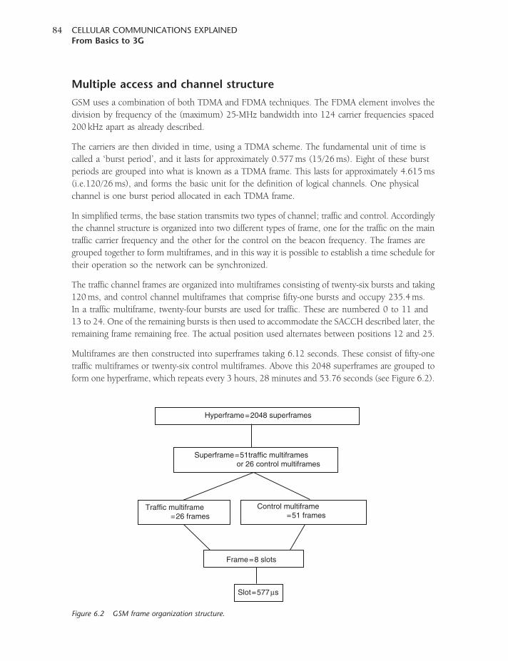
Multiple access and channel structure
GSM uses a combination of both TDMA and FDMA techniques. The FDMA element involves the
division by frequency of the (maximum) 25-MHz bandwidth into 124 carrier frequencies spaced
200 kHz apart as already described.
The carriers are then divided in time, using a TDMA scheme. The fundamental unit of time is
called a ‘burst period’, and it lasts for approximately 0.577ms (15/26ms). Eight of these burst
periods are grouped into what is known as a TDMA frame. This lasts for approximately 4.615ms
(i.e.120/26ms), and forms the basic unit for the definition of logical channels. One physical
channel is one burst period allocated in each TDMA frame.
In simplified terms, the base station transmits two types of channel; traffic and control. Accordingly
the channel structure is organized into two different types of frame, one for the traffic on the main
traffic carrier frequency and the other for the control on the beacon frequency. The frames are
grouped together to form multiframes, and in this way it is possible to establish a time schedule for
their operation so the network can be synchronized.
The traffic channel frames are organized into multiframes consisting of twenty-six bursts and taking
120ms, and control channel multiframes that comprise fifty-one bursts and occupy 235.4ms.
In a traffic multiframe, twenty-four bursts are used for traffic. These are numbered 0 to 11 and
13 to 24. One of the remaining bursts is then used to accommodate the SACCH described later, the
remaining frame remaining free. The actual position used alternates between positions 12 and 25.
Multiframes are then constructed into superframes taking 6.12 seconds. These consist of fifty-one
traffic multiframes or twenty-six control multiframes. Above this 2048 superframes are grouped to
form one hyperframe, which repeats every 3 hours, 28 minutes and 53.76 seconds (see Figure 6.2).
Hyperframe=2048 superframes
Traffic multiframe =26 frames
Frame=8 slots
Slot=577µs
Control multiframe =51 frames
Superframe=51traffic multiframes or 26 control multiframes
Figure 6.2 GSM frame organization structure.
CELLULAR COMMUNICATIONS EXPLAINEDFrom Basics to 3G
84
Control channels
There is a variety of different control channels that are used to provide the required functionality
to enable the mobiles and the BTS to communicate, set up and manage the calls. There are a
number of channels, and they can be split into groups, namely broadcast channels for initial
synchronization, common control channels for initiating calls, and dedicated control channels to
manage calls. The common channels include the following.
1. Broadcast channels:
� Frequency Correction Channel (FCCH). This is effectively a series of 148 zeros sent as the
first logical channel in the control sequence. As the burst is all zeros, this equates in GMSK
to a sine wave at a frequency of approximately 67 kHz. The mobile finds this and adjusts
its own frequency to be that of the network.
� Synchronization Channel (SCH). This is transmitted in time slot zero in the frame following
FCCH. It contains extended training sequences to allow the mobile to gain exact
synchronization with the network. Also contained within the sequence are the BTS
identification and the current frame location in relation to the hyperframe.
� Broadcast Control Channel (BCCH). This channel is continually broadcast on the
downlink, i.e. by the BTS. It contains information including base station identity,
frequency allocations, and frequency-hopping sequences that are needed by the mobiles
to set up and receive calls. One broadcast control channel segment occupies four frames
per multiframe.
2. Common control channels:
� Paging Channel (PCH). This channel is used to ‘page’ or call the mobile to let it know that
there is an incoming call. The location registers are able to identify the relevant cell for the
mobile, and a request is sent out for a particular mobile (on the paging channel that all
mobiles monitor periodically) to inform the mobile that there is an incoming call.
� Access Grant Channel (AGCH). This channel is used to set up a call once a mobile has been
paged on the paging channel or random access channel. It directs the mobile to another
control channel, typically the Slow Dedicated Control Channel (SDCCH), where the call
set up is progressed.
� Random Access Channel (RACH). This performs an equivalent function to that of
the paging channel, except that it is used when a mobile initiates a call. Accordingly,
it is located within the uplink from the mobile to the BTS. As the name implies, the
channel is accessed randomly as required by the mobile. As any mobile communicating
with the BTS can access this channel, there is the possibility that two mobiles will interfere
with one another. To overcome this problem, the BTS sends an acknowledgement to
the mobile once it has correctly accepted the access. If this does not occur, the mobile
waits a random amount of time before re-accessing via the RACH. On acceptance of
the access the BTS directs the mobile to the SDCCH, a two-way channel where the call
can be set up.
CHAPTER SIXGSM
85
3. Dedicated control channels:
� Standalone Dedicated Control Channel (SDCCH). This channel is used for messaging along
with the companion SACCH in order to relay signalling information. The channel takes four
bursts in each multiframe for each mobile that is active on the BTS, which is just sufficient
to enable timely transmission of the relevant data.
� Slow Associated Control Channel (SACCH). This channel is used to relay a variety of
information. On the downlink from the BTS to the mobile, this includes broadcast
messages which give the beacon frequencies of neighbouring cells, power control
information, and timing advance. For the uplink it includes the measurement report, which
gives the strength measurements from signals received from neighbouring cell beacon
transmissions, acknowledgement for the power control and acknowledgement for the
timing advance.
� Fast Associated Control Channel (FACCH). This channel is used to send urgent messages
that are normally unscheduled. As the SACCH may take seconds to transfer, this may not
be swift enough for many functions. In order to achieve much faster data transfer, the
messages are sent in place of speech data for short periods of time. Additionally, it comes
free when a TCH is activated, so part way through a call set-up signalling will move to
FACCH, not because it needs to be fast or is unscheduled, but because it is an available and
efficient resource. It is referred to as ‘fast’ because it can carry up to fifty messages per
second against four per second for SDCCH.
It is often possible to take up to about one in six of the traffic or speech frames without undue
loss of quality, although there is some degradation. When a frame of speech data is lost as a result
of the presence of an FACCH frame being sent, the same action is taken as when data is lost due
to poor signal or channel conditions. Here, the receiving end replaces the lost speech data with
a repeat of the previous sound. In this way the listener hears a persistence of the sound rather than
a silence or click, and in this way the missing data are masked sufficiently. As the number of frames
that are used by the FACCH increases, the degradation of the speech deteriorates. This happens in
a non-linear fashion as the number of frames increases.
It is necessary that the receiver knows whether a frame is traffic (i.e. speech or FACCH) so
that the data can be used correctly. To achieve this, the data are marked in each burst using
two flag bits. These are set to 0 for user or speech data and to 1 for FACCH data. Two data
bits are required because it is possible that the FACCH and speech data may be interleaved
where the data is spread between adjacent bursts, and only half the data may be speech and
half FACCH.
The traffic channel
As the name implies, the Traffic Channel (TCH) is used to carry the voice information for the call.
There are three basic types of traffic channel: full-rate, half-rate and eighth-rate. A full-rate traffic
channel (TCH/F) occupies a complete slot per frame, whereas a half-rate traffic channel (TCH/H)
CELLULAR COMMUNICATIONS EXPLAINEDFrom Basics to 3G
86
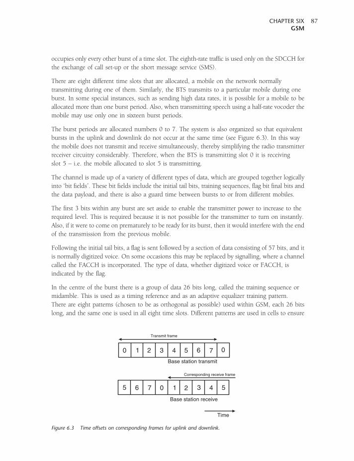
occupies only every other burst of a time slot. The eighth-rate traffic is used only on the SDCCH for
the exchange of call set-up or the short message service (SMS).
There are eight different time slots that are allocated, a mobile on the network normally
transmitting during one of them. Similarly, the BTS transmits to a particular mobile during one
burst. In some special instances, such as sending high data rates, it is possible for a mobile to be
allocated more than one burst period. Also, when transmitting speech using a half-rate vocoder the
mobile may use only one in sixteen burst periods.
The burst periods are allocated numbers 0 to 7. The system is also organized so that equivalent
bursts in the uplink and downlink do not occur at the same time (see Figure 6.3). In this way
the mobile does not transmit and receive simultaneously, thereby simplifying the radio transmitter
receiver circuitry considerably. Therefore, when the BTS is transmitting slot 0 it is receiving
slot 5 – i.e. the mobile allocated to slot 5 is transmitting.
The channel is made up of a variety of different types of data, which are grouped together logically
into ‘bit fields’. These bit fields include the initial tail bits, training sequences, flag bit final bits and
the data payload, and there is also a guard time between bursts to or from different mobiles.
The first 3 bits within any burst are set aside to enable the transmitter power to increase to the
required level. This is required because it is not possible for the transmitter to turn on instantly.
Also, if it were to come on prematurely to be ready for its burst, then it would interfere with the end
of the transmission from the previous mobile.
Following the initial tail bits, a flag is sent followed by a section of data consisting of 57 bits, and it
is normally digitized voice. On some occasions this may be replaced by signalling, where a channel
called the FACCH is incorporated. The type of data, whether digitized voice or FACCH, is
indicated by the flag.
In the centre of the burst there is a group of data 26 bits long, called the training sequence or
midamble. This is used as a timing reference and as an adaptive equalizer training pattern.
There are eight patterns (chosen to be as orthogonal as possible) used within GSM, each 26 bits
long, and the same one is used in all eight time slots. Different patterns are used in cells to ensure
0
0
1
1
2
2
3
3
4
4
5
5
6
6
7
7
0
5
Time
Base station transmit
Base station receive
Transmit frame
Corresponding receive frame
Figure 6.3 Time offsets on corresponding frames for uplink and downlink.
CHAPTER SIXGSM
87
that only the signal from the required BTS is recognized. With the movement of mobiles, signals
vary considerably, and it is possible that the signal from a nearby cell may be received suddenly.
The use of the training patterns enables the mobile to detect this.
The data, usually from the voice encoding, need to be split to fit the data structure. The speech is
broken into blocks of 20ms, and this is processed by the speech coder to give 260 bits to represent
the speech. These are ordered and divided into two groups. For full-rate speech, one group of
182 bits is passed through error correction and results in a string of 382 bits. The less critical group
of 78 bits is just summed with the error-corrected data to yield 482 bits. These are diagonally
interleaved to form 57 bits per time slot, the exact size of the data length in the data slots, two
per burst. As a result, the 20-ms sample of speech is sent over eight timeslots over the air.
A further flag and section of 57 bits of data follow. Finally there are three final tail bits where
the transmitter ramps down its power, and this is followed by a guard period to separate this
burst from the next. The guard period is equivalent to 8.25 bits.
Vocoders
If digitized in a linear fashion, the speech would occupy a far greater bandwidth than any cellular
system could accommodate. To overcome this, a variety of voice coding systems (or vocoders) are
used. These systems involve analysing the incoming data that represent the speech and then
performing a variety of actions upon the data to reduce the data rate. At the receiving end the
reverse process is undertaken to re-constitute the speech data so that it can be understood.
The original vocoder used in GSM was called LPC-RPE (Linear Prediction Coding with Regular
Pulse Excitation). This vocoder took each 20-ms block of speech and then represented it using just
260 bits. This actually equates to a data rate of 13 kbps.
In GSM, it is recognized that some bits are more important than others. If some bits are missed
or corrupted, it is more important to the voice quality than others. Accordingly, the different bits
are classified as:
� Class Ia, 50 bits – most important and sensitive to bit errors
� Class Ib, 132 bits – moderately sensitive to bit errors
� Class II, 78 bits – least sensitive to bit errors.
The 50 Class 1a bits are given a 3-bit Cyclic Redundancy Code (CRC) so that errors can be
detected. This makes a total length of 53 bits. If there are any errors, the frame is not used and is
discarded. In its place a version of the previously correctly received frame is used. These 53 bits,
together with the 132 Class Ib bits with a 4-bit tail sequence, are entered into a 1/2 rate
convolutional encoder. The total length is 189 bits. The encoder encodes each of the bits that enter
as 2 bits, the output also being dependent upon a combination of the previous 4 input bits.
As a result, the output from the convolutional encoder consists of 378 bits. The remaining 78 Class
II bits are considered the least sensitive to errors, so they are not protected and are simply added
to the data. In this way, every 20-ms speech sample generates a total of 456 bits. Accordingly,
CELLULAR COMMUNICATIONS EXPLAINEDFrom Basics to 3G
88
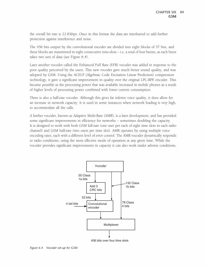
the overall bit rate is 22.8 kbps. Once in this format the data are interleaved to add further
protection against interference and noise.
The 456 bits output by the convolutional encoder are divided into eight blocks of 57 bits, and
these blocks are transmitted in eight consecutive time-slots – i.e. a total of four bursts, as each burst
takes two sets of data (see Figure 6.4).
Later another vocoder called the Enhanced Full Rate (EFR) vocoder was added in response to the
poor quality perceived by the users. This new vocoder gave much better sound quality, and was
adopted by GSM. Using the ACELP (Algebraic Code Excitation Linear Prediction) compression
technology, it gave a significant improvement in quality over the original LPC-RPE encoder. This
became possible as the processing power that was available increased in mobile phones as a result
of higher levels of processing power combined with lower current consumption.
There is also a half-rate vocoder. Although this gives far inferior voice quality, it does allow for
an increase in network capacity. It is used in some instances when network loading is very high,
to accommodate all the calls.
A further vocoder, known as Adaptive Multi-Rate (AMR), is a later development, and has provided
some significant improvements in efficiency for networks – sometimes doubling the capacity.
It is designed to work with both GSM full-rate (one user per each of eight time slots in each radio
channel) and GSM half-rate (two users per time slot). AMR operates by using multiple voice
encoding rates, each with a different level of error control. The AMR vocoder dynamically responds
to radio conditions, using the most effective mode of operation at any given time. While the
vocoder provides significant improvements in capacity it can also work under adverse conditions,
Vocoder
Add 3CRC bits
Convolutionalencoder
Multiplexer
4 tail bits
50 Class1a bits
53 bits
132 Class1b bits
78 ClassII bits
456 bits over four time slots
Figure 6.4 Vocoder set-up for GSM.
CHAPTER SIXGSM
89

including poor radio signal conditions, where errors are high and when the network is heavily
loaded. It is particularly useful at cell boundaries, where signal levels are lower and interference
levels may be higher.
There are eight full-rate modes within AMR, and these operate at: 12.2, 10.2, 7.95, 7.4, 6.7, 5.9,
5.15 and 4.75 kbps. The highest rate of 12.2 kbps is actually the same as the GSM EFR vocoder
and the 7.4 rate is the same as that used in ANSI-136 TDMA. The bit rate for each burst is
22.8 kbps. This includes both the voice data and the error correction information. By decreasing
the voice data, the error correction can be increased to allow for increased errors and the system can
therefore operate under poorer conditions by increasing the level of error correction. This can be
achieved dynamically.
There are also six half-rate modes that operate at rates of 7.95, 7.4, 6.7, 5.9, 5.15 and 4.75 kbps.
Since the gross bit rate in a half-rate channel is only 11.4 kbps, fewer bits are available for channel
coding. Accordingly, a better signal-to-noise ratio is required for half-rate operation. However, when
there is a good signal-to-noise ratio it can be enabled, allowing more users to access the same
number of radio channels. AMR half-rate mode is further enhanced in EDGE radio networks,
where more bits per time slot are available.
Operation
Initialization
When a GSM mobile phone is first turned on, it takes a few seconds before a call can be made.
Not only does the mobile have to initialize itself, but it also needs to connect to the network
so that it is ready to make and receive calls.
The first stage in linking to the network is to scan the available frequencies for a BTS. The mobile
will scan all the available frequencies, noting the signals that can be received. It also checks for
those signals that contain a control channel and notes the broadcast information, including the
system identification and access control information, including the initial transmit power.
The locations of messaging and paging channels are also sent. A unique identifier for the base
station is sent, along with a network identifier.
The mobile chooses the strongest beacon frequency and then, using the random access channel,
it sends a registration message. The network responds, checking the authentication and storing
the location of the mobile in the HLR or VLR, as appropriate.
Call initiation
When a call is made from a mobile, the mobile has to communicate with the BTS so that the
call can be set up and a connection made. It sends an access burst using the random access
channel. This message contains a 5-bit number that temporarily identifies the mobile to the
network. A further 3 bits contained within the message identify the type of message that is
being requested – page response, call origination, or even a reconnection of a temporarily lost call.
CELLULAR COMMUNICATIONS EXPLAINEDFrom Basics to 3G
90
There is a chance that another mobile will send a random access request at the same time, and
if no acknowledgement is received it will wait a random amount of time so that it does not clash
with the same mobile again, and then resend its access request.
When the BTS successfully receives the access request, it sends back the same random number
and directs the mobile to a specific radio channel and time slot. Normally the network will request
authentication and, if successful, the call can commence.
Receiving a call
A similar process to that used for a mobile-originated call is used for a call that needs to be received
by a specific mobile. There are obviously some differences, because the mobile has to be alerted
about the call rather than the mobile alerting the network that it needs to make a call.
When a request for a call is made to a specific mobile, the network checks the last registered
location of the mobile with the location register. The network then sends a page message on the
paging channel of a group of BTSs in the region where the mobile was last located.
When the mobile receives the paging message, it responds on its control channel. The network
then allocates a radio channel and time slot to which the mobile is sent. Once there the call is made
and continues until either end terminates the call.
Ending a call
A call may be terminated by either end of the connection. When this is detected, a number of
messages are exchanged between the network and the mobile. Several messages are sent to ensure
that the link has not been accidentally broken and that it is a real call termination.
Once the call is completed, the network frees the traffic channel for another user and the mobile
returns to its idle state monitoring the paging channel. It also checks to ensure that the BTS it
was using still offers the optimum signal. In this way it ensures that if any further calls arrive then
it is in the best position to receive them.
Handovers
One of the key elements of a mobile phone is that it is able to move and still remain connected.
This means that when the mobile moves out of the range of one BTS (i.e. out of a given cell) and
into the next, it must be possible to transfer the call without any noticeable interruption to the user.
It takes a considerable amount of the network’s time to ensure that this process, known as
handover, happens correctly, as it is an essential element of the network control. Any problems
quickly lead to customer dissatisfaction and a move to another network. The term for this is
‘churn’.
In GSM which uses TDMA techniques the transmitter transmits only for one slot in eight and,
similarly, the receiver receives only for one slot in eight. As a result, the RF section of the mobile
CHAPTER SIXGSM
91
could be idle for six slots out of the total eight. This is not the case, because during the slots in
which it is not communicating with the BTS it scans the other radio channels looking for beacon
frequencies that may be stronger or more suitable. In addition to this, when the mobile
communicates with a particular BTS one of the responses it makes is to send out a list of the radio
channels of the beacon frequencies of neighbouring BTSs. It scans these and reports back the
quality of the link to the BTS. In this way the mobile assists in the handover decision, and as
a result this is known as Mobile-Assisted HandOver (MAHO).
The network knows the quality of the link between the mobile and the BTS, as well as the strength
of local BTSs as reported back by the mobile. It also knows the availability of channels in the nearby
cells. As a result it has all the information it requires to be able to make a decision about whether it
needs to hand the mobile over from one BTS to another.
If the network decides that it is necessary for the mobile to hand over, it assigns a new channel
and time slot to the mobile. It informs the BTS and the mobile of the change. The mobile then
retunes during the period it is not transmitting or receiving, i.e. in an idle period.
Frequency hopping
One of the facilities that the GSM standard offers is to enable a mode of operation called frequency
hopping. This is effectively a form of spread spectrum operation. Essentially, when a signal
uses frequency hopping it moves from one frequency to another, staying on a particular
frequency for a short length of time, sufficient to send a burst of data. It then moves onto another
frequency, where it sends another burst of data. To operate in this mode, both transmitter and
receiver must follow the same hop pattern so that they are both on the same frequency at the
same time.
There are a number of advantages to frequency hopping. It is a technique that is used by the
military to prevent jamming by hostile signal sources, and it also prevents eavesdropping because
the signal cannot be received easily unless the hop pattern is known. For applications such
as cellular telecommunications, it is primarily used because it averages the level of interference.
By using frequency hopping, if one channel is blocked this will have only a transitory effect. Also,
as the channel is effectively shared by several mobiles hopping from one channel to the next, this
averages the level of interference. This has significant advantages for network planners, who often
have to design systems for worst-case situations; by adopting frequency hopping, average scenarios
can be taken. As a result of this, the level of frequency re-use can be improved, thereby bringing
considerable operational and financial advantages.
A further advantage is that it reduces the effects of selective fading. A signal that reaches a mobile
or BTS will be the sum of signals from the transmitter reaching the receiver via several paths as
a result of reflections. As the lengths of the paths will differ, sometimes the signals will add
constructively to produce a larger signal, whereas at other times they will tend to cancel each
other out. As this is somewhat dependent on the frequency in use, moving to a different channel
will often ease the situation. Again, the problem tends to be averaged out.
CELLULAR COMMUNICATIONS EXPLAINEDFrom Basics to 3G
92
Frequency hopping is relatively easy to implement in GSM because the RF section of the mobile is
already moving between different frequencies for transmit and receive, changing frequency during
the dead periods when neither the transmitter nor receiver are active.
In order to coordinate the transmit and receive channels and ensure that the BTS and mobile hop
in synchronism, the hopping algorithm is broadcast on the Broadcast Control Channel.
Short message service
The Short Message Service (SMS) is a feature that is widely used on GSM mobiles today. It provides
the ability to send and receive text messages to and from mobile telephones. The text can comprise
words or numbers, or an alphanumeric combination. SMS was created as part of the GSM Phase 1
standard, and its use has grown beyond all expectations. The first short message is believed to
have been sent in December 1992 from a Personal Computer (PC) to a mobile phone on the
Vodafone GSM network in the UK. Each short message is up to 160 characters in length when
Latin alphabets are used, and 70 characters in length when non-Latin alphabets (such as Arabic
and Chinese) are used.
SMS is what is termed a ‘store and forward’ service. The messages from the sender are routed to an
SMS centre and then on to the recipient. Each mobile telephone network that supports SMS has
one or more messaging centres to handle and manage the short messages. Once delivered a
confirmation of message is delivered, and this can be selected to appear at the user’s handset.
Short messages can be sent and received simultaneously with GSM voice, data and fax calls. This
is possible because voice, data and fax calls take over the traffic channel, whereas the SMS uses
the signalling path.
General packet radio service
As mobile phone technology became more widely used, it became obvious that data services
would become the next major generator of revenue. Although many second-generation systems
were able to carry data, it was only at very low data rates. For GSM, the maximum rate was
14.4 kbps.
As a result of this, developments were made to enable higher speed data to be carried over the
networks. The first was known as High Speed Circuit Switched Data (HSCSD). Although this was
never widely deployed, it enabled data rates of up to about 64 kbps to be achieved by combining
time slots. Although this enabled higher-speed data to be transferred, the concept was not widely
taken up because it did not make efficient use of the resources of the network.
Most data transfer occurs in what is often termed a ‘bursty’ fashion. The transfer occurs in short
peaks, and then remains quiescent for a while. This means that the channel remains dormant, even
though this capacity could be used to transfer data for other users. To overcome this problem,
CHAPTER SIXGSM
93
a system called the General Packet Radio Service (GPRS) was devised. Rather than using a circuit
switched scheme, where a complete circuit is devoted to a user, this scheme uses packet data and
enables a far greater level of efficiency to be obtained.
In addition to this, the data world is now very focused on the Internet and the protocols that it has
adopted. The 3G services have an IP-based structure, and with this in place it is easier to migrate to
the 3G standards such as UMTS/W-CDMA.
GPRS network structure
In order for the GPRS network structure to provide a packet-based service, the core network
structure has to be upgraded from what is used for GSM. The network between the BSC and BTS
is similar, but behind this, new infrastructure is required to support the packet data.
Data from the BSC is routed through what is termed a Serving GPRS Support Node (SGSN), which
forms the gateway to the services within the network, and then a Gateway GPRS Support Node
(GGSN), which forms the gateway to the outside world. These elements form what is known as the
Public Land Mobile Network (PLMN).
The SGSN serves a number of functions for mobiles with a data service. It enables authentication
to occur, and it then tracks the location of the mobile within the network and ensures that the
quality of service is of the required level.
For the network protocols there are two layers that are used and supported by GPRS, namely
X25 and IP. In operation, the protocols assign addresses (Packet Data Protocol or PDP addresses) to
the devices in the network for the purpose of routing the data through the system. Thus the
GGSN appears as a data gateway to the public packet network, and therefore the fact that the users
are mobiles cannot be identified.
In operation, the mobile must attach itself to the SGSN and activate its PDP address. This address
is supplied by the GGSN, which is associated with the SGSN. As a result a mobile can attach to only
one SGSN although, once assigned its address, it can receive data from multiple GGSNs using
multiple PDP addresses.
Layers
Software plays a very large part in the current cellular communications systems. To enable it to be
sectioned into areas that can be addressed separately, the concept of ‘layers’ has been developed.
It is used in GSM and other cellular systems, but as they become more datacentric the idea takes
a greater prominence. Often these are referred to as layers, 1, 2 and 3.
Layer 1 concerns the physical link between the mobile and the base station. This is often
subdivided into two sub-layers, namely the physical RF layer, which includes the modulation and
demodulation, and the physical link layer, which manages the responses and controls required
for the operation of the RF link. These include elements such as error correction, interleaving and
the correct assembly of the data, power control, and the like.
CELLULAR COMMUNICATIONS EXPLAINEDFrom Basics to 3G
94
Above this are the Radio Link Control (RLC) and the Medium Access Control (MAC) layers.
These organize the logical links between the mobile and the base station. They control the
radio link access and organize the logical channels that route the data to and from the mobile.
There is also the Logical Link Layer (LLC), which formats the data frames and is used to link the
elements of the core network to the mobile.
GPRS mobiles
In view of the increased capabilities that GPRS offers, the mobiles that are available are classified
according to their capabilities in terms of both the ability to connect to GSM and GPRS facilities,
and also the data rates they support. In the first instance, they are classified into three classes to
describe the way in which they can connect to the services available:
1. Class A describes mobile phones that can be connected to both GPRS and GSM services at the
same time.
2. Class B mobiles can be attached to both GPRS and GSM services, but they can be used on only
one service at a time. A Class B mobile can make or receive a voice call, or send and or
receive a SMS message during a GPRS connection. During voice calls or texting the GPRS
service is suspended, but it is re-established when the voice call or SMS session is complete.
3. Class C phones can be attached to either GPRS or GSM services, but the user needs to switch
manually between the two different types.
The mobiles are also categorized by the data rates they can support. In GSM there are eight time
slots that can be used to provide TDMA, allowing multiple mobiles onto a single RF signal carrier.
With GPRS it is possible to use more than one slot to enable much higher data rates to be achieved
when these are available. The different speed classes of the mobiles are dependent upon the
number of slots that can be used in either direction. There are a total of 29 speed classes: class 1
mobiles are able to send and receive in one slot in either direction (i.e. uplink and downlink), and
class 29 mobiles are able to send and receive in all eight slots. The classes between these two limits
are able to support sending and receiving in different combinations of uplink and downlink slots.
GPRS coding
GPRS offers a number of coding schemes with different levels of error detection and correction.
Their use is dependent upon the radio-frequency signal conditions and the requirements for the
data being sent. These are given labels CS-1 to CS-4:
� CS-1 applies the highest level of error detection and correction, and is used in scenarios when
interference levels are high or signal levels are low. By applying high levels of detection and
correction, this prevents the data having to be re-sent too often. Although it is acceptable for
many types of data to be delayed, for others there is a more critical time element. This level
of detection and coding results in a half code rate – that is, for every 12 bits that enter the coder,
24 bits result. It results in a 9.05-kbps actual throughput data rate.
CHAPTER SIXGSM
95
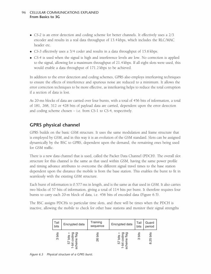
� CS-2 is an error detection and coding scheme for better channels. It effectively uses a 2/3
encoder and results in a real data throughput of 13.4 kbps, which includes the RLC/MAC
header etc.
� CS-3 effectively uses a 3/4 coder and results in a data throughput of 15.6 kbps.
� CS-4 is used when the signal is high and interference levels are low. No correction is applied
to the signal, allowing for a maximum throughput of 21.4 kbps. If all eight slots were used, this
would enable a data throughput of 171.2 kbps to be achieved.
In addition to the error detection and coding schemes, GPRS also employs interleaving techniques
to ensure the effects of interference and spurious noise are reduced to a minimum. It allows the
error correction techniques to be more effective, as interleaving helps to reduce the total corruption
if a section of data is lost.
As 20-ms blocks of data are carried over four bursts, with a total of 456 bits of information, a total
of 181, 268, 312 or 428 bits of payload data are carried, dependent upon the error detection
and coding scheme chosen – i.e. from CS-1 to CS-4, respectively.
GPRS physical channel
GPRS builds on the basic GSM structure. It uses the same modulation and frame structure that
is employed by GSM, and in this way it is an evolution of the GSM standard. Slots can be assigned
dynamically by the BSC to GPRS, dependent upon the demand, the remaining ones being used
for GSM traffic.
There is a new data channel that is used, called the Packet Data Channel (PDCH). The overall slot
structure for this channel is the same as that used within GSM, having the same power profile
and timing advance attributes to overcome the different signal travel times to the base station
dependent upon the distance the mobile is from the base station. This enables the burst to fit in
seamlessly with the existing GSM structure.
Each burst of information is 0.577ms in length, and is the same as that used in GSM. It also carries
two blocks of 57 bits of information, giving a total of 114 bits per burst. It therefore requires four
bursts to carry each 20-m block of data, i.e. 456 bits of encoded data (Figure 6.5).
The BSC assigns PDCHs to particular time slots, and there will be times when the PDCH is
inactive, allowing the mobile to check for other base stations and monitor their signal strengths
Tailbits
3 bi
ts
3 bi
ts
57 b
its +
1-bi
t cod
ing
sche
me
flag
57 b
its +
1-bi
t cod
ing
sche
me
flag
26 b
its
8.25
bits
Tailbits
Guardperiod
Encrypted data Encrypted dataTrainingsequence
Figure 6.5 Physical structure of a GPRS burst.
CELLULAR COMMUNICATIONS EXPLAINEDFrom Basics to 3G
96
to enable the network to judge when handover is required. The GPRS slot may also be used by
the base station to judge the time delay, using a logical channel known as the Packet Timing
Advance Control Channel (PTCCT).
Channel allocation
Although GPRS uses only one physical channel (PDCH) for the sending of data, it employs
several logical channels that are mapped into this to enable the GPRS data and facilities to
be managed. As the data in GPRS are handled as packet data rather than circuit switched data,
the way in which this is organized is very different to that on a standard GSM link. Packets
of data are assigned a space within the system according to the current needs, and routed
accordingly.
The MAC layer is central to this, and there are three MAC modes that are used to control the
transmissions: fixed allocation, dynamic allocation and extended dynamic allocation.
The fixed allocation mode is required when a mobile requires data to be sent at a consistent data
rate. To achieve this, a set of PDCHs are allocated for a given amount of time. When this mode is
used there is no requirement to monitor for availability, and the mobile can send and receive data
freely. This mode is used for applications such as video-conferencing.
When using the dynamic allocation mode, the network allocates time slots as they are required.
A mobile is allowed to transmit in the uplink when it sees an identifier flag known as the Uplink
Status Flag (USF) that matches its own. The mobile then transmits its data in the allocated slot.
This is required because up to eight mobiles can have potential access to a slot, but obviously only
one can transmit at any given time.
Extended dynamic allocation is also available. Use of this mode allows much higher data rates to be
achieved because it enables mobiles to transmit in more than one slot. When the USF indicates
that a mobile can use this mode, it can transmit in the number allowed, thereby increasing the rate
at which it can send data.
Logical channels
There is a variety of channels used within GPRS, and they can be set into groups dependent upon
whether they are for common or dedicated use (see below). Naturally, the system does use the
GSM control and broadcast channels for initial set-up, but all the GPRS actions are carried out
within the GPRS logical channels carried within the PDCH.
1. Common control channels
� Packet Broadcast Control Channel (PBCCH). This is a downlink-only channel that is used
to broadcast information to mobiles and informs them of incoming calls etc. It is very
similar in operation to the BCCH used for GSM. In fact the BCCH is still required in the
initialization to provide a time slot number for the PBCCH. In operation, the PBCCH
CHAPTER SIXGSM
97

broadcasts general information such as power control parameters, access methods and
operational modes, network parameters, etc., required to set up calls.
� Packet Paging Channel (PPCH). This is a downlink-only channel, and is used to alert the
mobile to an incoming call and to warn it to be ready to receive data. It is used for control
signalling prior to the call set-up. Once the call is in progress, a dedicated channel referred
to as the PACCH takes over.
� Packet Access Grant Channel (PAGCH). This is also a downlink channel, and it sends
information telling the mobile which traffic channel has been assigned to it. It occurs after
the PPCH has informed the mobile that there is an incoming call.
� Packet Notification Channel (PNCH). This is another downlink-only channel which is
used to alert mobiles that there is broadcast traffic intended for a large number of mobiles.
It is typically used in what is termed ‘point-to-point multicasting’.
� Packet Random Access Channel (PRACH). This is an uplink channel that enables the
mobile to initiate a burst of data in the uplink. There are two types of PRACH burst; one
is an 8-bit standard burst, and a second one using an 11-bit burst has added data to allow
for priority setting. Both types of burst allow for timing advance setting.
2. Dedicated control channels
� Packet Associated Control Channel (PACCH). This channel is present in both uplink and
downlink directions, and is used for control signalling while a call is in progress. It takes
over from the PPCH once the call is set up, and it carries information such as channel
assignments, power control messages and acknowledgements of received data.
� Packet Timing Advance Common Control Channel (PTCCH). This channel, which is
present in both the uplink and downlink directions, is used to adjust the timing advance.
This is required to ensure that messages arrive at the correct time at the base station,
regardless of the distance of the mobile from the base station. As timing is critical in a
TDMA system and signals take a small but finite time to travel, this aspect is very important
if long guard bands are not to be left.
3. Dedicated traffic channel
� Packet Data Traffic Channel (PDTCH). This channel is used to send the traffic and it is
present in both the uplink and downlink directions. Up to eight PDTCHs can be allocated
to a mobile to provide high-speed data.
GPRS operation
There are three modes in which a GPRS mobile may operate: initialization/idle, standby and ready.
When the mobile is turned on, it must register with the network and update the location register.
This is very similar to the action performed with a GSM mobile, but it is referred to as a location
update. It first locates a suitable cell and transmits a radio burst on the RACH, using a shortened
burst because it does not know what timing advance is required. The data contained within this
CELLULAR COMMUNICATIONS EXPLAINEDFrom Basics to 3G
98
burst temporarily identifies the mobile, and indicates that the reason for the update is to perform
a location update.
When the mobile performs its location update, the network also performs an authentication to
ensure that it is allowed to access the network. As with GSM, it accesses the HLR and VLR as
necessary for the location update and the AuC for authentication. It is at registration that the
network detects that the mobile has a GPRS capability. The SGSN also maintains a record of the
location of the mobile so that data can be sent there if required.
The mobile then enters a standby mode, periodically updating its position. It monitors the
MNC of the base station to ensure that it has not changed base stations, and looks for stronger
base-station control channels.
The mobile also monitors the PPCH in case of an incoming alert indicating that data are ready to be
sent. As with GSM, most base stations set up a schedule for paging alerts based on the last figures of
the mobile number. In this way it does not have to monitor all the available alert slots, and can
instead monitor a reduced number to which it knows alerts can be sent for it. In this way the
receiver can be turned off for longer and battery life can be extended.
In the ready mode, the mobile is attached to the system and a virtual connection is made with
the SGSN and GGSN. By making this connection, the network knows where to route the
packets when they are sent and received. In addition to this, the mobile is likely to use the
PTCCH to ensure that its timing is correctly set so that it is ready for a data transfer should one
be needed.
With the mobile attached to the network, it is prepared for a call or data transfer. To transmit data,
the mobile attempts a Packet Channel Request using the PRACH uplink channel. As this may be
busy, the mobile monitors the PCCCH, which contains a status bit indicating the status of the base
station receiver – whether it is busy, or idle and capable of receiving data. When the mobile sees
this status bit indicating that the receiver is idle, it sends its packet channel request message.
If accepted, the base station will respond by sending an assignment message on the PAGCH on
the downlink. This will indicate which channel the mobile is to use for its packet data transfer,
as well as other details required for the data transfer.
This sets up the packet data transfers for the uplink only. If data need to be transferred in the
downlink direction, then a separate assignment is performed for the downlink channel.
When data are transferred, this is controlled by the action of the MAC layer. In most instances it
will operate in an acknowledge mode, whereby the base station acknowledges each block of data.
The acknowledgement may be contained within the data packets being sent in the downlink, or the
base station may send data packets down purely to acknowledge the data.
When disconnecting, the mobile sends a packet temporary block flow message, and this is
acknowledged. Once this has taken place, the USF assigned to the mobile becomes redundant and
can be assigned to another mobile wanting access. At this point the mobile effectively becomes
disconnected and, although still attached to the network, no more data transfer takes place unless it
is re-initiated. Separate messages are needed to detach the mobile from the network.
CHAPTER SIXGSM
99
EDGE
EDGE is a further evolution of GSM, enabling higher data rates to be achieved but using
substantially the same network equipment. Effectively, it is an upgrade to GPRS. Although
upgrades are required at the base station, as there are differences to the radio interface, the
core network capability remains virtually unchanged, allowing migration to the new standard.
EDGE stands for either Enhanced Data for Global Evolution or for Enhanced Data for GSM
Evolution – both are widely used and accepted.
One of the main differences between EDGE and GPRS is that EDGE uses a different form of
modulation. GPRS uses the GMSK used on GSM, whereas EDGE, to achieve higher data rates, uses
a higher-order modulation format in the form of 8PSK (see Chapter 3). This means that instead
of the maximum payload per slot being 116 bits, as in the case of GPRS, it rises to 464 bits.
The packet technology used in GPRS is carried forward to EDGE, and this means that the upgrades
that are required are essentially within the BTS to enable it to transmit and receive 8PSK
modulation.
EDGE offers a significant speed improvement over GPRS, but this can only be achieved under
ideal conditions. The optimum radio conditions occur only when the signals in both directions
are sufficiently strong, and this normally entails the mobile being reasonably close to the base
station. Once a mobile starts to move, variations in signal strength are normally experienced
and these degrade the quality of the link.
Although 8PSK, being a higher-order modulation format, enables a three-fold increase in the
data transfer rate, this comes at the price of noise resilience. It is found that 8PSK is considerably
more sensitive to noise than GMSK, and this is why the higher data rate is available only under
good signal conditions.
Phones equipped for EDGE can be used for both circuit switched voice and packet switched data.
They can also operate on GPRS-only networks. In fact, the phone will use the higher-order 8PSK
modulation only when the conditions are suitable, returning to the GMSK modulation when
the link is not optimum for 8PSK.
The phones are grouped into classes dependent upon their capabilities. Class A equipment is
able to support simultaneous GSM voice along with GPRS/EDGE data; class B equipment can
support GSM voice and GPRS/EDGE data, but not simultaneously; and class C equipment can
support only GPRS/EDGE data services but no voice services.
Time slots
EDGE, GPRS and GSM all have to operate alongside each other in a network. It is a primary
requirement that evolutionary technologies are all able to operate on the same network.
This ensures that service is offered to existing customers using older phones along with those
paying additional rates for the premium EDGE services. The network therefore has to support both
services operating simultaneously. Accordingly, different slots within the traffic frames will need
to be able to support different structures and different types of modulation, dependent upon the
CELLULAR COMMUNICATIONS EXPLAINEDFrom Basics to 3G
100
phones being used, the calls being made and the prevailing conditions. It is quite possible that one
slot may be supporting a GSM call, the next a GPRS data connection and the third an EDGE
connection using 8PSK.
Table 6.2 provides a comparison of GPRS and EDGE data payloads.
Data coding and throughput
Most of the data being sent over an EDGE link consist of TCP/IP packets. These packets are
longer than a single EDGE packet payload, and therefore it is necessary to split the TCP/IP
packets into smaller sections known as ‘chunks’. These chunks have defined sizes, and may
consist of one of 22, 28, 34 or 37 bytes or ‘octets’. The 37-octet chunk may be made directly
of data to be transmitted, or it may be a 34-octet chunk which is then padded by adding three
dummy octets.
There are nine different Modulation and Coding Schemes (MCS) that can be used with EDGE,
and each one is designated a number in the region 1 to 9. These allow different degrees of error
protection (and coding rate), resulting in a change in the net data throughput. The system detects
the number of bit errors and adjusts the coding scheme accordingly. It naturally endeavours to
adopt the scheme that will result in the highest throughput, but will adjust itself according to the
prevailing conditions, changing as required.
The different coding schemes are grouped into three classes or families, which are referred to
as families A, B and C. The coding schemes within a family are used together and complement
one another (Table 6.3). Family A consists of MCS-3, MCS-6, MCS-8 and MCS-9; family B consists
Table 6.3 EDGE error protection and coding schemes.
Scheme name Effective code rate Modulation format Data rate using one time slot (kbps)
MCS-9 1.0 8PSK 59.2
MCS-8 0.92 8PSK 54.4
MCS-7 0.76 8PSK 44.8
MCS-6 0.49 8PSK 29.6
MCS-5 0.37 8PSK 22.4
MCS-4 1.0 GMSK 17.6
MCS-3 0.8 GMSK 14.8
MCS-2 0.66 GMSK 11.2
MCS-1 0.53 GMSK 8.8
Table 6.2 Comparison of GPRS and EDGE data payloads.
GPRS (using GMSK) EDGE (using 8PSK)
Overall payload per slot 116 464
Overall payload per block 348 1392
CHAPTER SIXGSM
101
of MCS-2, MCS-5 and MCS-7; and family C consists of MCS-1 and MCS-4. The advantage of
grouping the families together in this way is that if a block transmitted in one of the coding
schemes is not acknowledged, then it can be sent as two blocks with a coding scheme in the same
family. For example, if a block transmitted using MCS-7 is corrupted, then it can be re-sent as
two blocks using MCS-5 or four using MCS-2.
Operation
The overall operation of an EDGE network is virtually identical to that of GPRS. The same core
network components are used, as it is a migration from one to the next allowing higher data rates.
In fact, the differences occur at the air interface. Here, the new scheme sends data faster and is
more adaptive in terms of the modulation scheme and coding schemes used, so that the optimum
performance is achieved. It is also possible for a network to run simultaneous GSM, GPRS and
EDGE calls. The major upgrades are to the base station, where new hardware is normally required
to enable the transmission of 8PSK as well as GMSK modulation.
CELLULAR COMMUNICATIONS EXPLAINEDFrom Basics to 3G
102
7CHAPTER SEVEN
North American TDMA
While GSM was the second-generation digital cellular system that was introduced within Europe
initially, another development took place in the USA. There were different requirements, and as
a result the system, although digital and using Time-Division Multiple Access (TDMA) techniques,
is very different.
The FCC had indicated that no new frequency allocations were to be made to accommodate
a new cellular system. Therefore, with a very heavy investment in AMPS technology which had
been deployed over vast areas of the USA, there was a need to ensure that any digital system
that was developed was as compatible as possible with AMPS. In view of this, the system
was designed to use the existing AMPS channels so that it would allow a smooth transition
from AMPS to TDMA. During the changeover, both AMPS and TDMA could co-exist in the
same area.
Although using the same 30-kHz channel spacing as adopted by AMPS, TDMA provides a threefold
increase in voice traffic by splitting the voice channel using digitized voice, and using time slots for
three voice channels. In addition to the improvement in capacity, the system has also been made
secure against casual listening, cloning and other forms of fraud.
The system, which is primarily used only within North America, is known by a variety of names.
Today it is most commonly called just TDMA, in view of its time-division multiple access
technology. However, outside the USA it is often called NA or North American TDMA, for obvious
reasons. It is also called Digital AMPS (DAMPS) as well as US Digital Cellular (USDC), American
Digital Cellular (ADC) and North American Digital Cellular (NADC). Whatever name is used,
it is the same system.
The system was originally defined under the standard IS-54. However, the performance
of the system was upgraded to keep pace with some of the competing technologies, and
IS-54 was superseded by IS-136. This includes new features such as text messaging and data
capabilities.
Although the system in this format is used within North America, a variant was adopted in Japan.
Known as Pacific or Personal Digital Cellular (PDC), this is used exclusively in Japan, where has
it attained a very high degree of use and market penetration.
System overview
The NA-TDMA standard builds on many of the elements found in AMPS, containing many of the
features used in AMPS but implemented in a format suitable for a digital standard. It utilizes the
idea of control channels, as well as using different traffic channels onto which the calls are routed.
There are also features that are similar to the SAT tones used in AMPS.
The overall network architecture is similar to that of AMPS. Base stations are grouped together
under the control of a base station controller. This will manage or control a small number of base
stations and enable some of the local decisions and control to be effected close to the area where
the control is needed. This simplifies the central control that is required, and also makes
communication faster and more effective. The base station controllers are then connected back
to the mobile switching centre, which takes overall control of the network and links into the PSTN.
As before, the MSC contains the location registers for monitoring the location of mobiles on the
network, and also the database used for authentication of the mobiles attempting to gain access
to the network.
RF signal
The signals that are transmitted in NA-TDMA fall within a 30-kHz channel spacing, as already
discussed. To achieve this spacing while being able to accommodate a sufficiently high data rate
to support three digitized voice channels, a form of modulation known as DQPSK is used. This
enables data at a rate of 48.6 kbps to be fitted into the channel bandwidth of 30 kHz.
This approach provides a very high level of modulation efficiency. The overall level is 1.62 bps/Hz
(i.e. 48.6 kbps/30 kHz). Unfortunately there is a price to pay for this. One of the major
disadvantages is that the signal varies in amplitude as the modulation is applied. GSM uses a
form of modulation known as GMSK, and the amplitude of this remains constant. The use of
a form of modulation that gives a varying output amplitude requires that a linear amplifier is used
in the final stages of the transmitter of the mobile. As linear amplifiers are less efficient than those
that are non-linear, this reduces battery life. However, the system requires a very high modulation
efficiency, and this was part of the compromise needed in choosing the most suitable form of
modulation.
Even though NA-TDMA operates on 30-kHz channels, the digital information causes the spectrum
of the radio frequency signal to be different to that of the FM signal modulated with straight
analogue audio. As a result, the mask used to define the maximum bandwidth of the digital
signal is less stringent than that of the analogue transmissions, although still retaining a sufficiently
low level of signal in the adjacent channels to enable interference to be kept within acceptable
limits.
In addition to the 850-MHz band that was used for AMPS and the first deployment of
NA-TDMA defined under IS-54, the later release of the standard released under IS-136 allows
for transmissions in the PCS band at 1900MHz. This has given further capacity to systems that
CELLULAR COMMUNICATIONS EXPLAINEDFrom Basics to 3G
104
were reaching their limits. As a result, the frequency bands 869–894MHz and 1930–1990MHz
are used for the base station transmissions, and 824–849MHz and 1850–1910MHz for the
mobile transmissions.
Channels
When the first forms of NA-TDMA as defined under IS-54 were deployed the system operated in
a very similar way to AMPS, but instead of having an analogue voice or traffic channel it was
digital and enabled three voice channels to be accommodated on the single RF carrier. By allowing
the AMPS FOCC and RECC channels to remain, it was possible to run the two systems together
and give backward compatibility. Nevertheless, some upgrades were required to enable the
additional facilities required by NA-TDMA to operate.
In total, there are four messages required for authentication, three for FOCC and two for RECC.
These provide the required level of security to prevent a variety of forms of fraud that were prevalent
when using AMPS, such as cloning.
The message structure using RECC and FOCC has been updated to provide more flexibility and
allow both voice and data to be transferred, thereby allowing data (including SMS) to be carried.
On RECC, two additional messages have been introduced; Page Response With Service, and
Origination With Service. On FOCC, Page With Service and Message Waiting have been
introduced.
In order to direct the mobile to the correct digital channel for the call, a message known as Initial
Digital Traffic Channel has been introduced onto the FOCC. This enables the system to use the
FOCC and divide traffic channels between analogue and digital, thereby allowing analogue and
digital formats to operate satisfactorily alongside each other.
A further addition is new information that has been added into the Global Action Message.
The basic message was used in AMPS, but by adding a DCCH (Digital Control Channel) pointer
it enables the mobile to move to the allocated DCCH to receive its service.
Identifiers
Although the basic channel structure is approximately the same, there are naturally some
differences. There are both control and traffic channels. However, the base stations transmit what
is called a Digital Verification Colour Code (DVCC). This performs a very similar function to that of
the SAT signal transmitted for AMPS, where the tone indicated the group of stations to which a
particular base station belonged. Using the DVCC, a specific digital identification known as a
LOCAID is transmitted. This is allocated to a group of base stations, and provides a broad
indication of the area in which a mobile is located. If the mobile moves into a different area, it sees
a new LOCAID. By knowing the LOCAID the mobile is receiving, the network knows which
base stations need to page the mobile for an incoming call. This considerably reduces the load
on the network as it only has to send the page message to a limited number of base stations.
CHAPTER SEVENNorth American TDMA
105
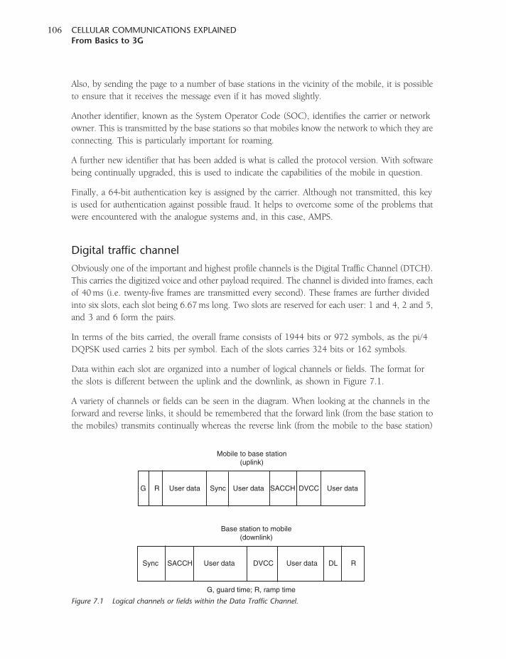
Also, by sending the page to a number of base stations in the vicinity of the mobile, it is possible
to ensure that it receives the message even if it has moved slightly.
Another identifier, known as the System Operator Code (SOC), identifies the carrier or network
owner. This is transmitted by the base stations so that mobiles know the network to which they are
connecting. This is particularly important for roaming.
A further new identifier that has been added is what is called the protocol version. With software
being continually upgraded, this is used to indicate the capabilities of the mobile in question.
Finally, a 64-bit authentication key is assigned by the carrier. Although not transmitted, this key
is used for authentication against possible fraud. It helps to overcome some of the problems that
were encountered with the analogue systems and, in this case, AMPS.
Digital traffic channel
Obviously one of the important and highest profile channels is the Digital Traffic Channel (DTCH).
This carries the digitized voice and other payload required. The channel is divided into frames, each
of 40ms (i.e. twenty-five frames are transmitted every second). These frames are further divided
into six slots, each slot being 6.67ms long. Two slots are reserved for each user: 1 and 4, 2 and 5,
and 3 and 6 form the pairs.
In terms of the bits carried, the overall frame consists of 1944 bits or 972 symbols, as the pi/4
DQPSK used carries 2 bits per symbol. Each of the slots carries 324 bits or 162 symbols.
Data within each slot are organized into a number of logical channels or fields. The format for
the slots is different between the uplink and the downlink, as shown in Figure 7.1.
A variety of channels or fields can be seen in the diagram. When looking at the channels in the
forward and reverse links, it should be remembered that the forward link (from the base station to
the mobiles) transmits continually whereas the reverse link (from the mobile to the base station)
G
RDL
Sync
Sync User dataUser data
User data User data User dataSACCH
SACCH
DVCC
DVCC
Mobile to base station(uplink)
Base station to mobile(downlink)
G, guard time; R, ramp time
R
Figure 7.1 Logical channels or fields within the Data Traffic Channel.
CELLULAR COMMUNICATIONS EXPLAINEDFrom Basics to 3G
106
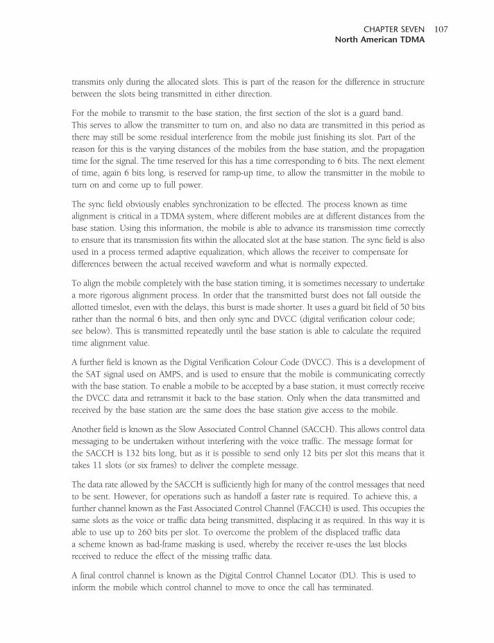
transmits only during the allocated slots. This is part of the reason for the difference in structure
between the slots being transmitted in either direction.
For the mobile to transmit to the base station, the first section of the slot is a guard band.
This serves to allow the transmitter to turn on, and also no data are transmitted in this period as
there may still be some residual interference from the mobile just finishing its slot. Part of the
reason for this is the varying distances of the mobiles from the base station, and the propagation
time for the signal. The time reserved for this has a time corresponding to 6 bits. The next element
of time, again 6 bits long, is reserved for ramp-up time, to allow the transmitter in the mobile to
turn on and come up to full power.
The sync field obviously enables synchronization to be effected. The process known as time
alignment is critical in a TDMA system, where different mobiles are at different distances from the
base station. Using this information, the mobile is able to advance its transmission time correctly
to ensure that its transmission fits within the allocated slot at the base station. The sync field is also
used in a process termed adaptive equalization, which allows the receiver to compensate for
differences between the actual received waveform and what is normally expected.
To align the mobile completely with the base station timing, it is sometimes necessary to undertake
a more rigorous alignment process. In order that the transmitted burst does not fall outside the
allotted timeslot, even with the delays, this burst is made shorter. It uses a guard bit field of 50 bits
rather than the normal 6 bits, and then only sync and DVCC (digital verification colour code;
see below). This is transmitted repeatedly until the base station is able to calculate the required
time alignment value.
A further field is known as the Digital Verification Colour Code (DVCC). This is a development of
the SAT signal used on AMPS, and is used to ensure that the mobile is communicating correctly
with the base station. To enable a mobile to be accepted by a base station, it must correctly receive
the DVCC data and retransmit it back to the base station. Only when the data transmitted and
received by the base station are the same does the base station give access to the mobile.
Another field is known as the Slow Associated Control Channel (SACCH). This allows control data
messaging to be undertaken without interfering with the voice traffic. The message format for
the SACCH is 132 bits long, but as it is possible to send only 12 bits per slot this means that it
takes 11 slots (or six frames) to deliver the complete message.
The data rate allowed by the SACCH is sufficiently high for many of the control messages that need
to be sent. However, for operations such as handoff a faster rate is required. To achieve this, a
further channel known as the Fast Associated Control Channel (FACCH) is used. This occupies the
same slots as the voice or traffic data being transmitted, displacing it as required. In this way it is
able to use up to 260 bits per slot. To overcome the problem of the displaced traffic data
a scheme known as bad-frame masking is used, whereby the receiver re-uses the last blocks
received to reduce the effect of the missing traffic data.
A final control channel is known as the Digital Control Channel Locator (DL). This is used to
inform the mobile which control channel to move to once the call has terminated.
CHAPTER SEVENNorth American TDMA
107
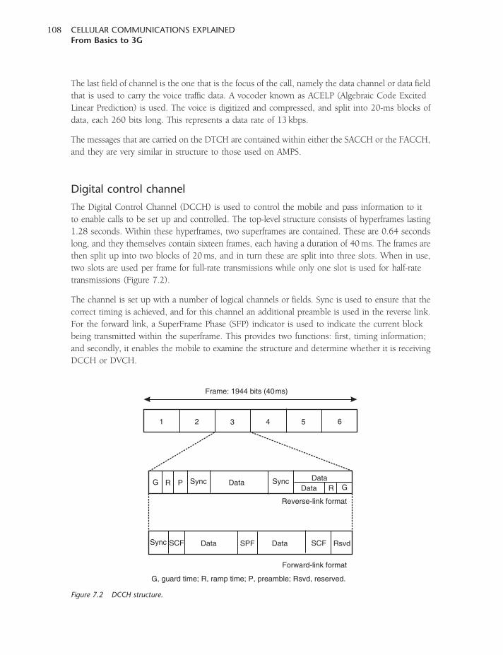
The last field of channel is the one that is the focus of the call, namely the data channel or data field
that is used to carry the voice traffic data. A vocoder known as ACELP (Algebraic Code Excited
Linear Prediction) is used. The voice is digitized and compressed, and split into 20-ms blocks of
data, each 260 bits long. This represents a data rate of 13 kbps.
The messages that are carried on the DTCH are contained within either the SACCH or the FACCH,
and they are very similar in structure to those used on AMPS.
Digital control channel
The Digital Control Channel (DCCH) is used to control the mobile and pass information to it
to enable calls to be set up and controlled. The top-level structure consists of hyperframes lasting
1.28 seconds. Within these hyperframes, two superframes are contained. These are 0.64 seconds
long, and they themselves contain sixteen frames, each having a duration of 40ms. The frames are
then split up into two blocks of 20ms, and in turn these are split into three slots. When in use,
two slots are used per frame for full-rate transmissions while only one slot is used for half-rate
transmissions (Figure 7.2).
The channel is set up with a number of logical channels or fields. Sync is used to ensure that the
correct timing is achieved, and for this channel an additional preamble is used in the reverse link.
For the forward link, a SuperFrame Phase (SFP) indicator is used to indicate the current block
being transmitted within the superframe. This provides two functions: first, timing information;
and secondly, it enables the mobile to examine the structure and determine whether it is receiving
DCCH or DVCH.
Frame: 1944 bits (40ms)
Reverse-link format
Forward-link format
G, guard time; R, ramp time; P, preamble; Rsvd, reserved.
1
G R P Sync SyncData
Data SPF RsvdData SCFSync SCF
R GDataData
2 3 4 5 6
Figure 7.2 DCCH structure.
CELLULAR COMMUNICATIONS EXPLAINEDFrom Basics to 3G
108
A field referred to as the Shared Channel Feedback (SCF) field is used to maintain the reverse
channel transmissions. It contains three sub-fields, namely the BRI, R/N and CPE fields. The first
field is the Busy/Reserved/Idle (BRI) field, which informs the mobile whether the RACH is being
used, and hence whether it can access the system to make a call. The Received/Not Received (R/N)
field is used to indicate the result of a random access, along with the Coded Partial Echo (CPE)
field. Additionally, the user data may be abbreviated in a shortened burst and, as shown in
Figure 7.2, one of two formats may be adopted dependent upon the amount of data to be
transmitted.
Data on the forward channel falls into two categories or channels, namely a BroadCast CHannel
(BCCH) and a Short message Paging and Access response CHannel (SPACH).
Paging
The way in which mobiles are paged can have a bearing on a number of elements of the
overall performance. One in particular is the battery life. By arranging the paging messaging
such that many of the circuits within the mobile can be switched off while the mobile is not
involved in a call, it is possible to conserve power and considerably extend the life of the
battery. Accordingly, mobiles have a ‘sleep’ mode and the channel structure has been organized
to facilitate this.
When there is an incoming call for a mobile, the mobile is alerted using the paging sub-channels in
the SPACH blocks. These are transmitted twice, once in each superframe found in the hyperframes.
By enabling the mobile to close down during some superframes and listen in to specific ones only,
it is able to shut off its circuitry for part of the time.
The MIN within the mobile determines which paging channels the mobile will listen to, and
the length of time the mobile is allowed to sleep is determined by the Paging Frame Number.
A number 1 means that the mobile will monitor one paging channel in each hyperframe.
The maximum 96 means that the mobile will sleep through 96 hyperframes. While the mobile
sleeps, it cannot pick up paging messages. As each hyperframe takes 1.28 seconds, if the PFN is
equal to 1 then the mobile will be able to identify an incoming call quickly. A PFN of 96 equates
to 122.88 seconds, meaning that it might take up to this time for the mobile to realize that there
is an incoming call. However, battery life in the idle mode would be very good.
Handoff
In order to determine whether the station needs to handoff to another base station, the mobile
makes a determination of the bit error rate (BER). This gives not only an indication of the signal
strength, but also the level of interference. This is a far more useful indication of whether a handoff
is required.
CHAPTER SEVENNorth American TDMA
109
The mobile is provided with information detailing channels where it might look for other local base
stations. This information is contained within a message called the Measurement Order, and it
contains six or twelve different channels where the mobile may look.
While the mobile is undertaking a call, it is able to monitor the signal strength and BER from
the signals surrounding base stations with the information provided from the measurement order.
As the system uses TDMA, the mobile is able to undertake the measurements during the time when
it is not transmitting or receiving. The results of these measurements (BER and RSSI – Received
Signal Strength Indication) are returned to the base station as a Channel Quality message using the
SACCH.
If the network decides that a handoff is required, then the mobile is allocated a new channel and
moves to this. The actual channel allocation and base station is determined by the reports sent back
to the network from the mobile.
Authentication
NA-TDMA was developed after the first-generation analogue systems were established.
These systems were open to fraud, and there were many instances of this. To overcome this,
preventive measures were introduced into the second-generation systems. Being digital, this was
much easier to achieve.
The authentication processes were standardized within IS-41C, and this is independent of
the air interface. Accordingly, this has also been also adopted for other schemes, including
cdmaOne/IS-95. It consists of a several-step process, and is additionally undertaken at several
different stages, including registration, call origination and call termination, and when the
mobile moves to a new location.
The Authentication Centre (AuC) is at the core of the process. It is the database at the centre
of the network where much of the private authentication data is stored. A 64-bit number known
as the A key is stored in each mobile in a way that is cannot be known even by the user. It is also
not transmitted over the air.
A number known as the Shared Secret Data (SSD) is used; this consists of a 128-bit
number which itself consists of two 64-bit sections. These are known as SSD_A and SSD_B.
The first of these, SSD_A, is used for authentication purposes, while SSD_B is used for voice
encryption.
The SSD is generated using both the A key and the Electronics Serial Number (ESN) held within
the mobile. This enables the SSD to be changed if the network feels that security may have been
compromised.
By utilizing these techniques the authentication process and network security can be successfully
maintained.
CELLULAR COMMUNICATIONS EXPLAINEDFrom Basics to 3G
110
PDC
In Japan, the second-generation TDMA cellular system is very similar to NA-TDMA and is known
as PDC. This stands for either Pacific Digital Cellular or Personal Digital Cellular. The standard
was defined by RCR, which later became ARIB, the Japanese standards organization. The first
service was launched in March 1993 by NTT DoCoMo, and by 2003 the system had over
61 million subscribers. The system is used nowhere else in the world, and is now being phased
out with the advent of 3G services. Both UMTS and CDMA2000 are being rolled out.
PDC uses a 25-kHz carrier spacing with three time slots. The modulation used is pi/4-DQPSK, and
this enables it to carry low bit-rate 11.2-kb/s and 5.6-kb/s (half-rate) vocoder data. The signalling
is very similar to that employed on NA-TDMA. The bands used for the service are 800MHz
(downlink 810–888MHz, uplink 893–958MHz) and also 1.5 GHz (downlink 1477–1501MHz,
uplink 1429–1453MHz). The services include voice (full- and half-rate), supplementary services
(call waiting, voice mail, three-way calling, call forwarding and so on), data service (up to 9.6 kbps
CSD) and packet switched wireless data (up to 28.8 kbps PDC-P).
CHAPTER SEVENNorth American TDMA
111

8CHAPTER EIGHT
cdmaOne/IS-95
While spread spectrum techniques had been used for many years in military circles, and then
primarily for covert communications systems, it was not until 1989 that the idea of using direct
sequence spread spectrum techniques in the form of a code division multiple access scheme was
proposed to the Telecommunications Industry Association in the USA. As there was already
another second-generation technology being developed, the industry did not want competing
technology to be introduced. Accordingly, the first CDMA networks were not launched in the USA,
from where the idea had emanated. Instead the first network was launched in Hong Kong in 1994,
with the first network in the USA being launched in 1996.
The idea of using direct sequence spread spectrum techniques to provide an access technology
was quite revolutionary. It was a major leap in technology over the original FDMA schemes used
for the first-generation networks, and also the TDMA systems being rolled out as GSM, initially
in Europe, and the NA-TDMA system being rolled out in the USA. It relied heavily on the much
greater levels of digital signal processing power that were coming and as such formed a significant
development in the approach used for mobile communications.
As described in Chapter 3, CDMA relies on the use of different orthogonal spreading codes to
differentiate between the different mobiles accessing the system. Although the signals all occupy
the same frequency channel, the system is able to decipher each signal by applying the correct code
to correlate the incoming signal and decipher it.
Standards
The first CDMA system was defined under IS-95. The first revision, termed IS-95A, was released
in 1995, and specified the air interface for a cellular, 800-MHz frequency band. ANSI J-STD-008
specified the PCS version (i.e. the air interface for 1900MHz). Later, the IS-95 standard was revised
to give IS-95B. This merged the IS-95A, ANSI J-STD-008 and others. Additionally, it specified
‘high-speed’ data operation with a maximum bit rate of 115.2 kbps. Although the system was
defined by a number of standards, it was marketed under the brand name cdmaOne. It is this name
that will be seen in any sales information.
Spreading codes
As a CDMA system is based on direct sequence spread spectrum techniques, the core of the system
revolves around the use of the orthogonal chip or spreading codes. The codes used in cdmaOne
are called Walsh codes, and the system combines these with two pseudo-random noise (PN) codes
for each communication channel. By using a number of different codes, it is possible to create
different channels. These can either be used for control applications or for carrying the data
payload. The different channels can then be separated by the receiver, as the receiver is only able
to correlate those for which it has been provided with the required Walsh codes. All other signals
using other Walsh codes just appear as noise.
The Walsh codes used for cdmaOne have a fixed length of 64 bits, and this allows for a maximum
of sixty-four individual physical channels to be carried by the system. The maximum number of
usable channels is limited by the level of interference from outside, possibly adjacent cells, and the
data throughput on each channel. This means that as interference from neighbouring cells rises so
do the interference levels, and the capacity of a given cell becomes less. This may mean that it is
not possible to utilize all the channels, and less than the maximum sixty-four may be used.
A further type of code, known as a PN code, is used in assembling the signal. Called
pseudo-random noise codes, they consist of a series of bits that have random properties. Three PN
codes are used within cdmaOne, two short codes and one long one.
These codes are used because they have some particularly useful properties. If one code is
time-shifted, it is found that the two copies of the same code become uncorrelated. This means
that the same code can be used twice, but time-shifted to provide two uncorrelated sequences.
In fact, when used in the network the codes are synchronized to triggers that are synchronized
to GPS timing signals.
In order to utilize the PN codes, an approach using a mask is adopted. Codes transmitted at a
different time offset are uncorrelated, and therefore by adopting a known given set of offsets it is
possible to create a set of ‘codes’ that can be used. The short codes are 32 768 bits long and offset
by 64 bits. This gives a total of 512 offsets that can be used. As the short code is transmitted
at the CDMA data rate of 1.2288Mbps, this equates to a full cycle time of 26.667ms.
As will be seen in later explanations, a process known as ‘decimation’ is used when generating
the channels. This is a process where only part of the data acquired is actually used. If only 1 out
of 5 bits is used, then the sequence is decimated by a factor of 5:1.
Radio signal construction
CDMA transmissions are very different to those used for the previous FDMA and TDMA systems.
Here, the system occupied a relatively narrow bandwidth. For a CDMA system, a much wider
bandwidth is used. In the case of IS-95/cdmaOne, a channel bandwidth of 1.25MHz is used.
The actual bandwidth is determined by the chip rate, which is 1.228Mcps. Additionally, in another
CELLULAR COMMUNICATIONS EXPLAINEDFrom Basics to 3G
114

departure from previous practice, adjacent cells are able to use the same frequency, the different
codes used by the adjacent cells enabling them to work alongside each other.
The characteristics of the transmission between the forward and reverse links are slightly different.
Much of this arises from the fact that the two links are on different frequencies, and the path
lengths are different in terms of the number of wavelengths travelled. In the forward link, a form of
modulation known as Quadrature Phase Shift Keying (QPSK) is used. This allows 2 bits per symbol
to be transmitted, and is therefore an efficient method of transmitting the data. In the reverse
channel, a form of modulation known as Offset Quadrature Phase Shift Keying (OQPSK) is used.
This is a form of quadrature phase shift keying where the quadrature (Q) component of the signal
is offset from the in-phase (I) component by half a symbol period. As a result the amplitude of
the resulting waveform does not cross zero, and this reduces the peak-to-average ratio. This has
advantages for power amplifiers because the reduction enables more efficient signal amplifiers to
be made in the mobile, where battery consumption is a key parameter.
Channels
The channels in cdmaOne can be split into those used for the forward link and those used
for the reverse link. The channels between these two links differ slightly, and will be treated
separately. The reason that the uplink and downlink are treated differently is that Walsh codes
need to be synchronized if they are to remain orthogonal. As the signals transmitted from the
mobile stations travel over different distances because of the variety of locations of the mobiles,
they will all arrive at slightly different times and hence will not be synchronized with one another.
The addition of the PN code overcomes this problem, even though Walsh codes have been used
for part of the spreading process in the mobile.
Forward link code channels
There are sixty-four code channels that can be accommodated on each CDMA RF channel.
Of these there are three overhead channel types: the pilot channel, the paging channels (of which
there may be up to seven) and the Sync channel. Beyond these channels, the remaining codes can
be traffic channels. Their arrangement is shown in Figure 8.1.
The data from the individual channels are multiplied with the Walsh codes to provide the
individual channels. The product is then further multiplied with the short PN codes explained
above (Figure 8.2). This has the effect of acting as an identifier for the sector/cell in question.
In this way, the mobile can determine from which cell the signal is coming.
Pilot channel
The Pilot Channel (PC) acts as a timing beacon for the system, and as a result it carries no data.
In fact the data is a stream of zeros, and these are spread using Walsh code 0, which is also a
CHAPTER EIGHTcdmaOne/IS-95
115
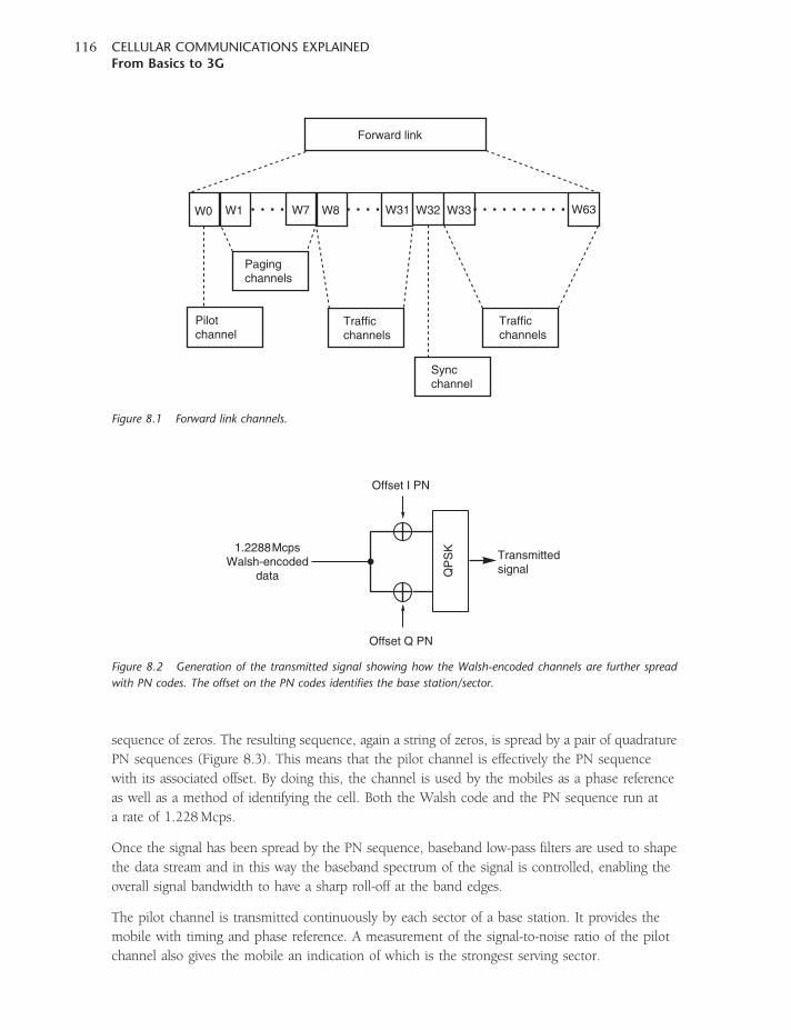
sequence of zeros. The resulting sequence, again a string of zeros, is spread by a pair of quadrature
PN sequences (Figure 8.3). This means that the pilot channel is effectively the PN sequence
with its associated offset. By doing this, the channel is used by the mobiles as a phase reference
as well as a method of identifying the cell. Both the Walsh code and the PN sequence run at
a rate of 1.228Mcps.
Once the signal has been spread by the PN sequence, baseband low-pass filters are used to shape
the data stream and in this way the baseband spectrum of the signal is controlled, enabling the
overall signal bandwidth to have a sharp roll-off at the band edges.
The pilot channel is transmitted continuously by each sector of a base station. It provides the
mobile with timing and phase reference. A measurement of the signal-to-noise ratio of the pilot
channel also gives the mobile an indication of which is the strongest serving sector.
Forward link
W0
Pilotchannel
Pagingchannels
Trafficchannels
Trafficchannels
Syncchannel
W1 W7 W8 W31 W32 W33 W63
Figure 8.1 Forward link channels.
QP
SK
Transmittedsignal
Offset I PN
Offset Q PN
1.2288McpsWalsh-encoded
data
Figure 8.2 Generation of the transmitted signal showing how the Walsh-encoded channels are further spread
with PN codes. The offset on the PN codes identifies the base station/sector.
CELLULAR COMMUNICATIONS EXPLAINEDFrom Basics to 3G
116
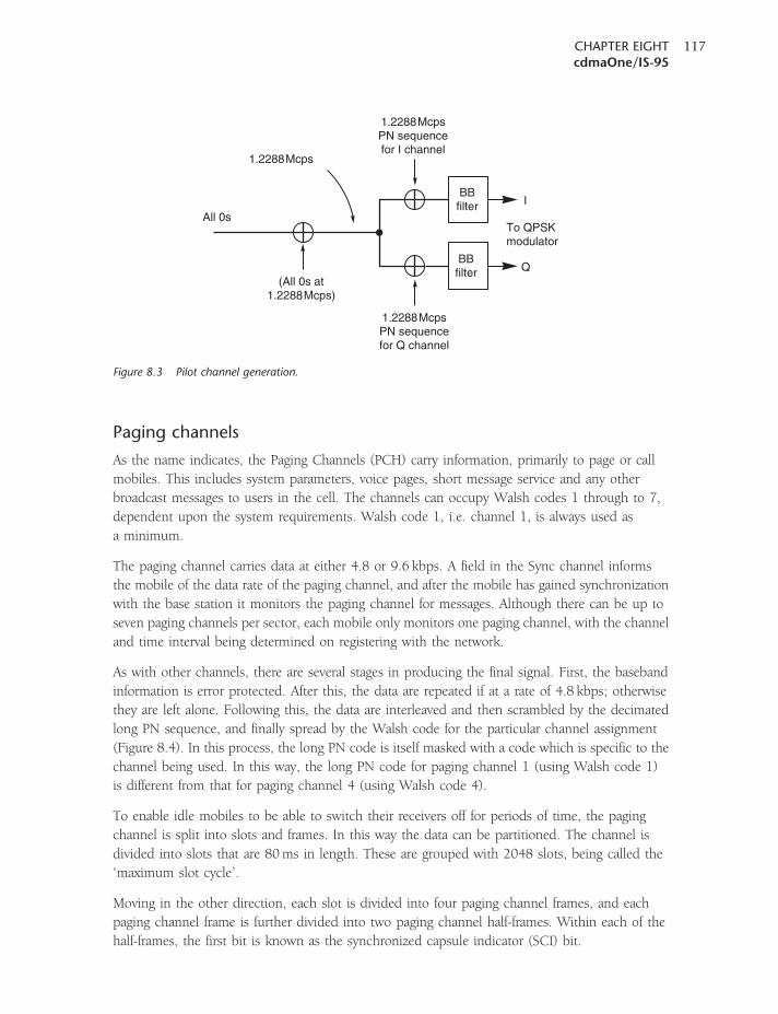
Paging channels
As the name indicates, the Paging Channels (PCH) carry information, primarily to page or call
mobiles. This includes system parameters, voice pages, short message service and any other
broadcast messages to users in the cell. The channels can occupy Walsh codes 1 through to 7,
dependent upon the system requirements. Walsh code 1, i.e. channel 1, is always used as
a minimum.
The paging channel carries data at either 4.8 or 9.6 kbps. A field in the Sync channel informs
the mobile of the data rate of the paging channel, and after the mobile has gained synchronization
with the base station it monitors the paging channel for messages. Although there can be up to
seven paging channels per sector, each mobile only monitors one paging channel, with the channel
and time interval being determined on registering with the network.
As with other channels, there are several stages in producing the final signal. First, the baseband
information is error protected. After this, the data are repeated if at a rate of 4.8 kbps; otherwise
they are left alone. Following this, the data are interleaved and then scrambled by the decimated
long PN sequence, and finally spread by the Walsh code for the particular channel assignment
(Figure 8.4). In this process, the long PN code is itself masked with a code which is specific to the
channel being used. In this way, the long PN code for paging channel 1 (using Walsh code 1)
is different from that for paging channel 4 (using Walsh code 4).
To enable idle mobiles to be able to switch their receivers off for periods of time, the paging
channel is split into slots and frames. In this way the data can be partitioned. The channel is
divided into slots that are 80ms in length. These are grouped with 2048 slots, being called the
‘maximum slot cycle’.
Moving in the other direction, each slot is divided into four paging channel frames, and each
paging channel frame is further divided into two paging channel half-frames. Within each of the
half-frames, the first bit is known as the synchronized capsule indicator (SCI) bit.
BBfilter
BBfilter
I
Q
To QPSKmodulator
1.2288McpsPN sequencefor I channel
1.2288McpsPN sequencefor Q channel
All 0s
(All 0s at1.2288Mcps)
1.2288Mcps
Figure 8.3 Pilot channel generation.
CHAPTER EIGHTcdmaOne/IS-95
117
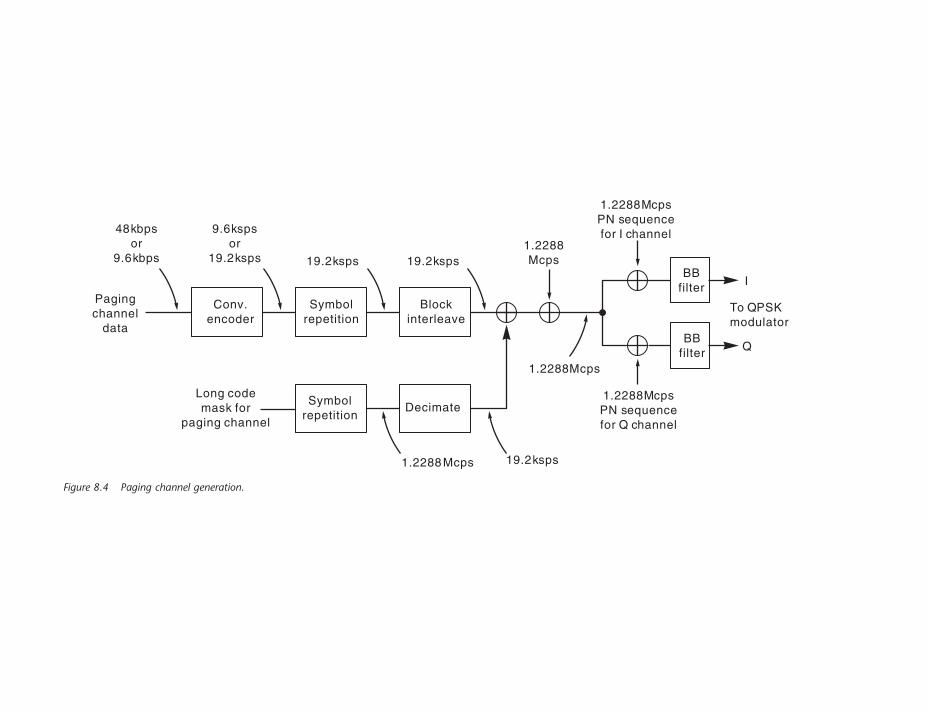
BBfilter
BBfilter
I
Q
To QPSKmodulator
1.2288McpsPN sequencefor I channel
1.2288McpsPN sequencefor Q channel
1.2288Mcps
1.2288Mcps
19.2ksps 19.2ksps
9.6kspsor
19.2ksps
48kbpsor
9.6kbps
Blockinterleave
Decimate
Symbolrepetition
Conv.encoder
Pagingchannel
data
Symbolrepetition
Long codemask for
paging channel
1.2288Mcps 19.2ksps
Figure 8.4 Paging channel generation.
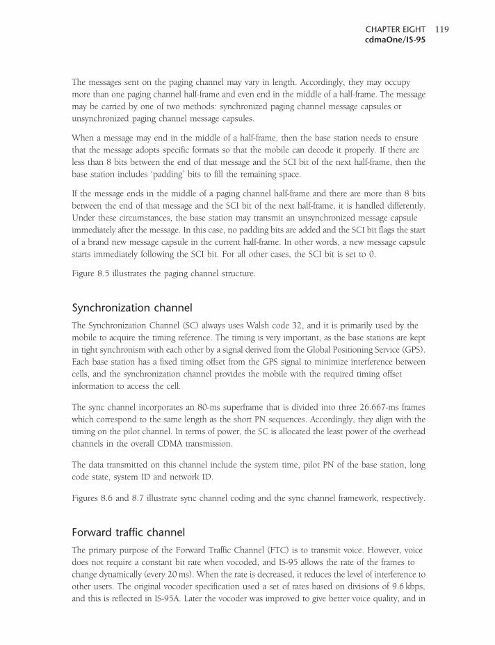
The messages sent on the paging channel may vary in length. Accordingly, they may occupy
more than one paging channel half-frame and even end in the middle of a half-frame. The message
may be carried by one of two methods: synchronized paging channel message capsules or
unsynchronized paging channel message capsules.
When a message may end in the middle of a half-frame, then the base station needs to ensure
that the message adopts specific formats so that the mobile can decode it properly. If there are
less than 8 bits between the end of that message and the SCI bit of the next half-frame, then the
base station includes ‘padding’ bits to fill the remaining space.
If the message ends in the middle of a paging channel half-frame and there are more than 8 bits
between the end of that message and the SCI bit of the next half-frame, it is handled differently.
Under these circumstances, the base station may transmit an unsynchronized message capsule
immediately after the message. In this case, no padding bits are added and the SCI bit flags the start
of a brand new message capsule in the current half-frame. In other words, a new message capsule
starts immediately following the SCI bit. For all other cases, the SCI bit is set to 0.
Figure 8.5 illustrates the paging channel structure.
Synchronization channel
The Synchronization Channel (SC) always uses Walsh code 32, and it is primarily used by the
mobile to acquire the timing reference. The timing is very important, as the base stations are kept
in tight synchronism with each other by a signal derived from the Global Positioning Service (GPS).
Each base station has a fixed timing offset from the GPS signal to minimize interference between
cells, and the synchronization channel provides the mobile with the required timing offset
information to access the cell.
The sync channel incorporates an 80-ms superframe that is divided into three 26.667-ms frames
which correspond to the same length as the short PN sequences. Accordingly, they align with the
timing on the pilot channel. In terms of power, the SC is allocated the least power of the overhead
channels in the overall CDMA transmission.
The data transmitted on this channel include the system time, pilot PN of the base station, long
code state, system ID and network ID.
Figures 8.6 and 8.7 illustrate sync channel coding and the sync channel framework, respectively.
Forward traffic channel
The primary purpose of the Forward Traffic Channel (FTC) is to transmit voice. However, voice
does not require a constant bit rate when vocoded, and IS-95 allows the rate of the frames to
change dynamically (every 20ms). When the rate is decreased, it reduces the level of interference to
other users. The original vocoder specification used a set of rates based on divisions of 9.6 kbps,
and this is reflected in IS-95A. Later the vocoder was improved to give better voice quality, and in
CHAPTER EIGHTcdmaOne/IS-95
119
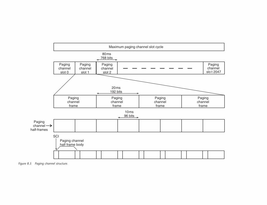
Maximum paging channel slot cycle
Pagingchannelslot 0
Pagingchannel
half-frames
Pagingchannelslot 1
Pagingchannelslot 2
Pagingchannel
slo t 2047
80ms768 bits
Pagingchannelframe
20ms192 bits
10ms96 bits
SCIPaging channelhalf frame body
Pagingchannelframe
Pagingchannelframe
Pagingchannelframe
Figure 8.5 Paging channel structure.
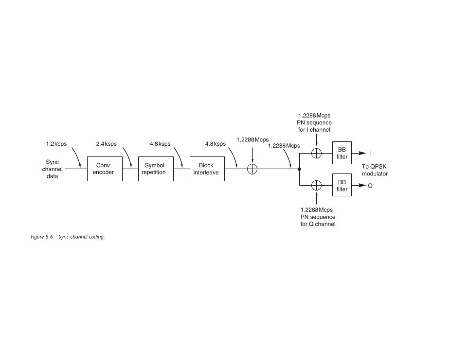
BBfilter I
Q
To QPSKmodulator
1.2288McpsPN sequencefor I channel
1.2288McpsPN sequencefor Q channel
1.2288Mcps1.2288Mcps1.2kbps
Blockinterleave
Symbolrepetition
Conv.encoder
Syncchannel
data
2.4ksps 4.8ksps 4.8ksps
BBfilter
Figure 8.6 Sync channel coding.
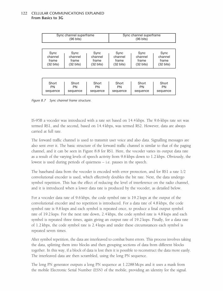
IS-95B a vocoder was introduced with a rate set based on 14.4 kbps. The 9.6-kbps rate set was
termed RS1, and the second, based on 14.4 kbps, was termed RS2. However, data are always
carried at full rate.
The forward traffic channel is used to transmit user voice and also data. Signalling messages are
also sent over it. The basic structure of the forward traffic channel is similar to that of the paging
channel, and it can be seen in Figure 8.8 for RS1. Here, the vocoder varies its output data rate
as a result of the varying levels of speech activity from 9.6 kbps down to 1.2 kbps. Obviously, the
lowest is used during periods of quietness – i.e. pauses in the speech.
The baseband data from the vocoder is encoded with error protection, and for RS1 a rate 1/2
convolutional encoder is used, which effectively doubles the bit rate. Next, the data undergo
symbol repetition. This has the effect of reducing the level of interference on the radio channel,
and it is introduced when a lower data rate is produced by the vocoder, as detailed below.
For a vocoder data rate of 9.6 kbps, the code symbol rate is 19.2 ksps at the output of the
convolutional encoder and no repetition is introduced. For a data rate of 4.8 kbps, the code
symbol rate is 9.6 ksps and each symbol is repeated once, to produce a final output symbol
rate of 19.2 ksps. For the next rate down, 2.4 kbps, the code symbol rate is 4.8 ksps and each
symbol is repeated three times, again giving an output rate of 19.2 ksps. Finally, for a data rate
of 1.2 kbps, the code symbol rate is 2.4 ksps and under these circumstances each symbol is
repeated seven times.
After symbol repetition, the data are interleaved to combat burst errors. This process involves taking
the data, splitting them into blocks and then grouping sections of data from different blocks
together. In this way, if a block of data is lost then it is possible to reconstruct the data more easily.
The interleaved data are then scrambled, using the long PN sequence.
The long PN generator outputs a long PN sequence at 1.2288Mcps and it uses a mask from
the mobile Electronic Serial Number (ESN) of the mobile, providing an identity for the signal.
Syncchannelframe
(32 bits)
ShortPN
sequence
Sync channel superframe(96 bits)
Sync channel superframe(96 bits)
Syncchannelframe
(32 bits)
Syncchannelframe
(32 bits)
Syncchannelframe
(32 bits)
Syncchannelframe
(32 bits)
Syncchannelframe
(32 bits)
ShortPN
sequence
ShortPN
sequence
ShortPN
sequence
ShortPN
sequence
ShortPN
sequence
Figure 8.7 Sync channel frame structure.
CELLULAR COMMUNICATIONS EXPLAINEDFrom Basics to 3G
122
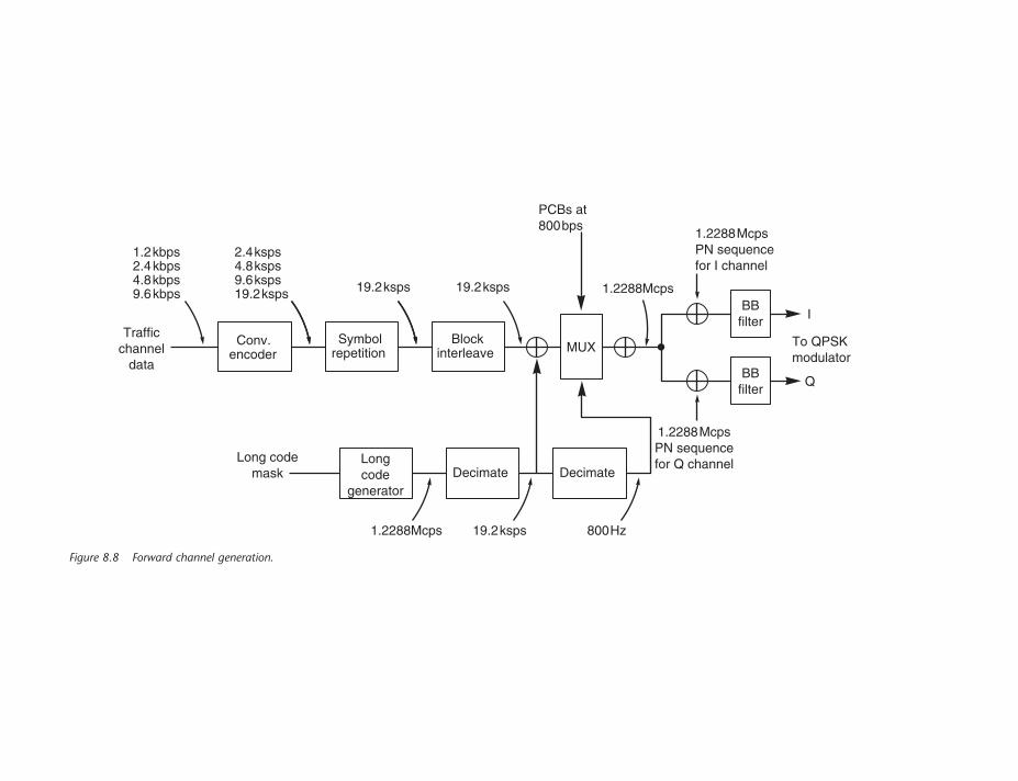
BBfilter
I
Q
To QPSKmodulator
1.2288McpsPN sequencefor I channel
1.2288McpsPN sequencefor Q channel
1.2288Mcps
Blockinterleave
Decimate
MUXSymbol
repetition
Decimate
Conv.encoder
Longcode
generator
Trafficchannel
data
PCBs at800bps
Long codemask
1.2288Mcps 19.2ksps 800Hz
1.2kbps2.4kbps4.8kbps9.6kbps
2.4ksps4.8ksps9.6ksps19.2ksps 19.2ksps 19.2ksps
BBfilter
Figure 8.8 Forward channel generation.
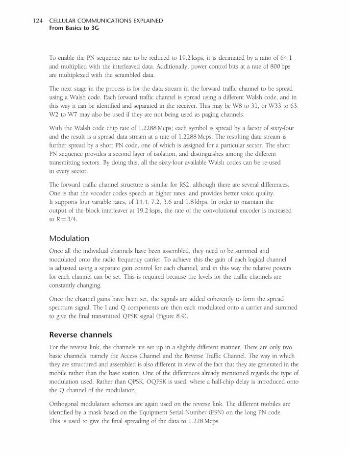
To enable the PN sequence rate to be reduced to 19.2 ksps, it is decimated by a ratio of 64:1
and multiplied with the interleaved data. Additionally, power control bits at a rate of 800 bps
are multiplexed with the scrambled data.
The next stage in the process is for the data stream in the forward traffic channel to be spread
using a Walsh code. Each forward traffic channel is spread using a different Walsh code, and in
this way it can be identified and separated in the receiver. This may be W8 to 31, or W33 to 63.
W2 to W7 may also be used if they are not being used as paging channels.
With the Walsh code chip rate of 1.2288Mcps; each symbol is spread by a factor of sixty-four
and the result is a spread data stream at a rate of 1.2288Mcps. The resulting data stream is
further spread by a short PN code, one of which is assigned for a particular sector. The short
PN sequence provides a second layer of isolation, and distinguishes among the different
transmitting sectors. By doing this, all the sixty-four available Walsh codes can be re-used
in every sector.
The forward traffic channel structure is similar for RS2, although there are several differences.
One is that the vocoder codes speech at higher rates, and provides better voice quality.
It supports four variable rates, of 14.4, 7.2, 3.6 and 1.8 kbps. In order to maintain the
output of the block interleaver at 19.2 ksps, the rate of the convolutional encoder is increased
to R¼ 3/4.
Modulation
Once all the individual channels have been assembled, they need to be summed and
modulated onto the radio frequency carrier. To achieve this the gain of each logical channel
is adjusted using a separate gain control for each channel, and in this way the relative powers
for each channel can be set. This is required because the levels for the traffic channels are
constantly changing.
Once the channel gains have been set, the signals are added coherently to form the spread
spectrum signal. The I and Q components are then each modulated onto a carrier and summed
to give the final transmitted QPSK signal (Figure 8.9).
Reverse channels
For the reverse link, the channels are set up in a slightly different manner. There are only two
basic channels, namely the Access Channel and the Reverse Traffic Channel. The way in which
they are structured and assembled is also different in view of the fact that they are generated in the
mobile rather than the base station. One of the differences already mentioned regards the type of
modulation used. Rather than QPSK, OQPSK is used, where a half-chip delay is introduced onto
the Q channel of the modulation.
Orthogonal modulation schemes are again used on the reverse link. The different mobiles are
identified by a mask based on the Equipment Serial Number (ESN) on the long PN code.
This is used to give the final spreading of the data to 1.228Mcps.
CELLULAR COMMUNICATIONS EXPLAINEDFrom Basics to 3G
124
The mobile transmits for a portion of the time, and this not only increases the battery life but
also serves to keep the overall level of interference to a minimum to ensure that the cell capacity
is kept as high as possible.
Access channel
The Access Channel (AC) is used by the mobile to communicate with the base station
when no traffic channel has been set up. It therefore uses the channel for call origination
requests, and also to carry the responses to paging commands sent by the network to
the mobile.
There can be up to 32 access channels on the reverse link for each paging channel on the downlink.
Each AC uses the PN, but time-shifted to enable it to be uniquely identified. Data are sent at
4800 bps in a 20-ms timeframe, so that each frame contains 96 bits.
Gaincontrol
Gaincontrol
A
a
Gaincontrol
Gaincontrol
B
b
Gaincontrol
Gaincontrol
C
c
Gaincontrol
Gaincontrol
DI
dI
Gaincontrol
Gaincontrol
DM
dM
Su
m in
pu
tsS
um
inp
uts
Sum Output
cos ω
sin ω
Figure 8.9 Modulator used for the forward link.
CHAPTER EIGHTcdmaOne/IS-95
125
Modulation
To generate the signal, the baseband information is first error protected using a convolutional
encoder. Symbols are then repeated once to give a code symbol rate of 28.8 ksps. The data
are interleaved and then coded using a 64-ary orthogonal modulator.
The set of sixty-four Walsh functions is used, but here the Walsh functions are used to modulate
groups of six symbols. The reason for orthogonal modulation of the symbols arises from the fact
that the mobiles are not synchronized in the same way as are the transmissions from the base
station. This means that the signals arriving at the base station will not be coherent, because the
receiver in the base station will receive signals with different timings due to small timing errors
in the mobile and also the different transmission times resulting from the different path lengths
from the mobiles to the base stations. When the transmission of a mobile is not coherent, the
receiver (at the base station) still has to detect each symbol correctly. Making a decision as to
whether or not a symbol is þ1 or �1 is difficult when judged over the period of one symbol.
To overcome this, if a group of six symbols is represented by a unique Walsh code, then the
base station can easily detect six symbols at a time by deciding which Walsh function is sent during
that period. Unlike the forward link, where the Walsh codes are used to distinguish between
different channels, on the reverse link they are used to distinguish between different groups of
six symbols. Thus the receiver can easily identify which Walsh function is being transmitted by
correlating the received sequence with the set of sixty-four known Walsh functions. In other
words, the six-symbol pattern dictates which Walsh code is used. If a pattern of þ1, �1, �1, þ1,
þ1, þ1 is to be sent, this corresponds to a binary value of 100111, which has a decimal value
of 39. Accordingly, Walsh code 37 is used.
The orthogonally modulated data are then spread by a long PN sequence running at a rate
of 1.2288Mcps, which is used to distinguish the access channel from the channels in the
reverse link. The data are further scrambled in the I and the Q paths by the short PN sequences
running at 1.2288Mcps. Data in the Q leg are delayed by half a chip to give OQPSK modulation
(Figure 8.10).
Information is transmitted in access channel slots and access channel frames. Each frame contains
96 bits and lasts 20ms, giving a baseband data rate of 4.8 kbps. The data comprise 88 information
bits and 8 encoder tail bits. There are two types of messages sent on the access channel: a response
message (in response to a base station message) or a request message (sent by the mobile station).
Reverse traffic channel
The Reverse Traffic Channel (RTC) carries variable rate data consisting of voice, data, control
information, etc. The frames contained within the channel are variable-rate frames at 4800, 2400 or
1200 bps.
The structure of the reverse traffic channel is similar to that of the access channel, but additionally
it includes a data burst randomizer into which the orthogonally modulated data are fed. The data
burst randomizer is the technique by which the voice activity factor is accounted for on the reverse
CELLULAR COMMUNICATIONS EXPLAINEDFrom Basics to 3G
126
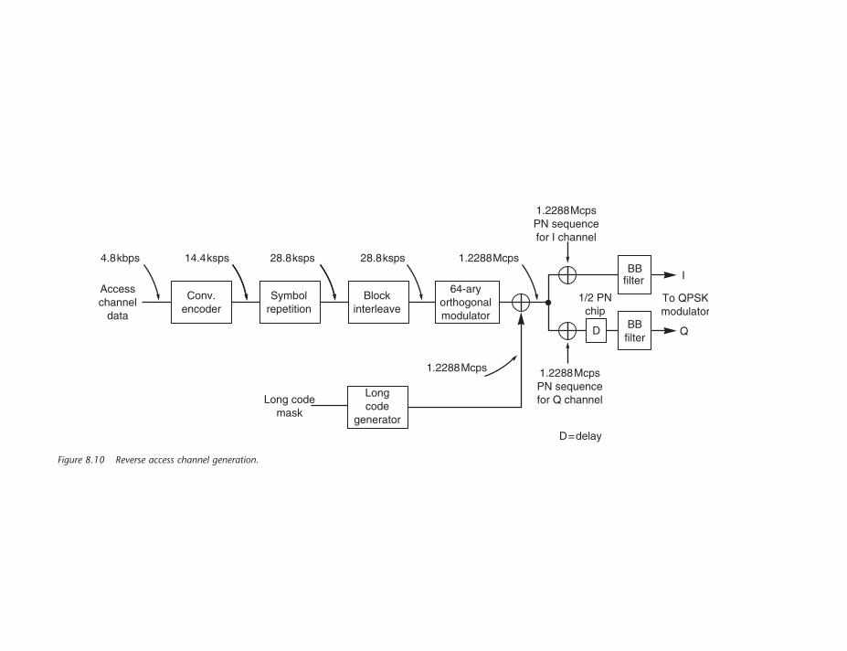
BBfilter
BBfilter
I
Q
To QPSKmodulator
1.2288McpsPN sequencefor I channel
1.2288McpsPN sequencefor Q channel
1.2288Mcps28.8ksps 28.8ksps14.4ksps4.8kbps
Blockinterleave
Symbolrepetition
Conv.encoder
Longcode
generator
Accesschannel
data
Long codemask
1.2288Mcps
64-aryorthogonalmodulator
D
D=delay
1/2 PNchip
Figure 8.10 Reverse access channel generation.
link. It is not possible to use the same techniques used on the reverse link that are used on the
forward link because they affect the channel power. This would upset the power control
adjustments that need to be made to ensure that all the mobiles are received as close to the same
strength as possible. Accordingly, a method that does not upset the measurements taken in the
base station needs to be adopted.
For the reverse link, the technique used is pseudo-randomly to switch off the transmitter during
redundant symbols produced by symbol repetition. This is accomplished by the data burst
randomizer. It first creates a mask that randomly masks out redundant data. This is partially
governed by the vocoder rate. If the vocoder is operating at 9.6 kbps then no data are masked, but
if, for example, the vocoder is operating at 1.2 kbps then the symbols are repeated seven times, and
the data burst randomizer masks out seven of eight groups of symbols.
The traffic channel frames are divided into sixteen Power Control Groups (PCG), each 1.25ms
in length, and accordingly the data burst randomizer pseudo-randomly masks out individual power
control groups to enable the power control to be maintained correctly. When the vocoder operates
at 9.6 kbps, no PCGs are masked out; when the vocoder operates at 4.8 kbps, an average of
eight PCGs are masked out in a frame. While the masking pattern is mainly dependent upon
the vocoder rate it is also dependent upon the long PN sequence used to spread the previous frame,
and this is used in determining the masking pattern.
Like the forward traffic channel, the reverse traffic channel frames are 20ms long. At full rate it
contains 192 bits, i.e. a data rate of 9.6 kbps, while at half rate it contains 96 bits, giving a data rate
of 4.8 kbps, etc. The full-rate and half-rate frames contain frame quality indicator Cyclic
Redundancy Check (CRC) bits, and all frames contain encoder tail bits.
The traffic channel is used to carry voice and data traffic as well as signalling. In fact, the system can
multiplex primary or voice traffic with the secondary or signalling traffic. There are two techniques
that are used, although only on full-rate frames. The first is known as ‘blank and burst’. Here, the
entire traffic channel frame is used to send only secondary data, while the entire traffic channel
frame is used to send only signalling data. The secondary or signalling data effectively blank out
the primary data. The second technique is known as ‘dim and burst’. With this the traffic channel
is used to send both primary and secondary data, although the primary traffic is only sent at half
rate – i.e. 80 bits per frame – or sometimes more.
Power control
In order for the receiver to receive all the incoming signals at approximately the same strength,
power control is of great importance. Accordingly, IS-95 provides three different power control
mechanisms. Power control is particularly important in the reverse link to the base station, where it
is necessary to keep all the mobiles at approximately the same strength so that the stronger mobiles
do not mask the weaker ones in an effect known as the near–far effect. Accordingly, both open-loop
and fast closed-loop power control are employed. In the downlink, a relatively slow power control
loop controls the transmission power.
CELLULAR COMMUNICATIONS EXPLAINEDFrom Basics to 3G
128
Open-loop power control
Open-loop power control provides a broad level of power control. Accordingly, it is used to adjust
the initial access channel transmission power of the mobile station and to compensate for large,
abrupt variations in signal strength. To use it, the mobile station determines an estimate of the path
loss between the base station and mobile by measuring the received signal strength at the mobile.
This measurement is then used to determine the power level the mobile will use when accessing
the system.
Closed-loop power control
The forward and reverse links have a frequency separation of 45MHz, and as a result the fading and
many of the path loss variations do not correlate well. Even though the average power is
approximately the same, the short-term power resulting from small changes in position, etc., is
different. This means that the open-loop power control mechanism cannot accurately set the
required power level to give the correct signal at the base station, and hence the closed-loop power
mechanism is required. To achieve this, the base station measures the received signal-to-
interference ratio (SIR) over a 1.25-ms period, which is equivalent to twenty-four modulation
symbols. It then compares this to a target SIR, and decides whether the mobile station transmission
power needs to be increased or decreased. The power control bits are transmitted to the mobile on
the downlink traffic channel every 1.25ms, giving a transmission rate of 800Hz, and this is
achieved by puncturing the data symbols. The placement of a power control bit is randomized
within the 1.25-ms power control group. The transmission occurs in the second power control
group following the corresponding uplink traffic channel power control group in which the SIR
was estimated. The power control commands are transmitted uncoded, and this is why they are
transmitted at full-rate power, regardless of the frame rate. However, any errors are made less
critical by the fact that the power is continually monitored and altered accordingly, up or down.
Thus errors in the power correction data are soon compensated.
On receipt of the power control commands, the mobile extracts the power control bit commands
and adjusts its transmission power accordingly. The adjustment step depends upon the system,
and may be 0.25, 0.5 or 1.0 dB. The dynamic range for the closed-loop power control is �24 dB.
The composite dynamic range for open and closed loop power control is �32 dB for mobile
stations operating in the North American cellular band around 850MHz, and �40 dB for mobile
stations operating in the PCS band around 1900MHz.
Downlink slow power control
Although the power control in the downlink is less critical than in the uplink, it is nevertheless
important. It serves to improve the performance of mobile stations at a cell edge where the signal is
weak and the interfering base station signals are strong. The base station periodically reduces the
transmitted power to the mobile station. For this control, the mobile measures the Frame Error
Ratio (FER) for the received signal. When this exceeds a predefined limit, typically 1 per cent, the
mobile station requests additional power from the base station. This adjustment is not as swift as
CHAPTER EIGHTcdmaOne/IS-95
129
that used for the reverse link, and occurs every 15–20ms. The dynamic range is also limited,
with an adjustment range of only �6 dB.
Handoff
One of the advantages of CDMA systems is associated with handoff. As a result of the fact that the
same frequency is used for adjacent cells, mobiles are able to receive signals from more than one
base station at the same time. Normally they would reject all but the signal from the wanted base
station as part of the decoding process. However, the ability to receive more than one signal is
advantageous when handing off from one cell to the next. During the handoff process, the two
adjacent cells both send the same data to the mobile. The mobile listens to both signals, and when
the handoff is complete the mobile returns to listening to just the one base station. This approach
significantly reduces the possibility of a call being dropped during handoff, and it also ensures
optimum voice quality when a mobile is on the edge of a cell. This form of handoff is known as
a ‘soft’ handoff.
Whilst soft handoff appears to be a significant advantage, there is a downside to the process.
The first is that it reduces the system capacity. The reason for this is simply that it requires
two channels or codes, one for each base station. It is estimated that this can reduce system
capacity by as much as 40 per cent, but this is dependent upon many factors, including the
duration of the handoff, the size of the cells and the level of overlap between the cells. There are
disadvantages for the mobile as well in that it requires two receivers or demodulators to be able to
monitor the two cells. Whilst this adds complexity to the mobile, it can be overcome by integrating
the additional functions into the main IC, and therefore the cost is relatively small. Despite these
disadvantages, the advantages of a much smoother and more reliable handoff are worth the
additional costs.
There is another form of handoff called a ‘softer’ handoff. This occurs when a mobile moves
between sectors on the same base station. As elements of the processing are shared, this enables
a ‘softer’ handoff to be accomplished even more easily than a soft handoff.
It may also be necessary for a mobile to undergo a ‘hard’ handoff. Under these circumstances, the
mobile is instructed to change channels. This is considerably more involved than the soft handoff,
because it is necessary for the mobile physically to break the connection with one base station
before connecting to the next. Hard handoff is also required when handing off from IS-95 to an
analogue network.
Discontinuous reception
In order to conserve battery capacity, the mobile is able to enter a sleep mode when it is idle and
only listens for paging data periodically. Under these conditions the mobile shuts down any
unnecessary areas of the circuitry, the receiver being one, and wakes them up only as required.
In this way, the current drain on the battery can be minimized.
CELLULAR COMMUNICATIONS EXPLAINEDFrom Basics to 3G
130
The mobile will undertake tasks such as monitoring the paging channel. There is a cycle set up to
do this, and it is in multiples of 1.28 seconds with a maximum period of just over 168 seconds.
The parameters for the sleep mode are set up when the mobile registers with the base station.
In this way, the mobile does not miss any messages being sent to it.
Call processing
Call processing is the complete process that enables calls to be successfully routed through to a
mobile to enable users to communicate with another user at some other location, whether he or
she is on another mobile phone or connected to a land line.
In IS-95, there are four states that the mobile passes through from power to accepting a call.
Although the process may appear somewhat simple, it needs to capture all the errors that may
occur in real life, and this complicates the picture considerably. However, to gain an overview
the main steps will be addressed in turn, and the host of possible error conditions will not be
addressed here.
The four states are termed MS initialization, MS idle state, system access state, and finally, MS traffic
state (Figure 8.11).
The first state that the mobile enters after it is powered on is known as initialization. When entering
this state the mobile performs a cell search, listening for the primary paging channel on Walsh code
1. From the information it gains, it is able to determine which of the cells is the strongest and the
most suitable to access. The mobile also acquires the pilot channel and then, using the sync
channel, it gains synchronization with the base station, synchronizing its long PN code and system
timing with that of the base station. It also registers with the network, and is allocated a time period
or slot for monitoring the paging channel. The length of this slot is determined between the base
station and the mobile.
Having achieved initialization, the next phase is for the mobile to be able to enter the idle
state – the name being given because to the user the mobile appears to be idle. In reality, it is
undertaking a large number of processes. The mobile periodically listens to the paging channel,
as described above, but to reduce the drain on the battery the mobile powers much of the
circuitry down, monitoring the paging channel only when pages are likely to appear. The mobile
also undertakes various acknowledgement procedures, and re-registration if required. This may be
necessary in a number of circumstances, such as after a certain time has elapsed, or when the
mobile moves to a new cell.
The mobile enters what is known as the access state when activity commences. This may be to
receive an incoming call or to initiate an outgoing call. During this phase the network determines
which channels are available, and then the mobile is allocated a traffic channel on receiving what is
termed a ‘traffic assignment message’.
Once the resource for the call has been committed, it enters the traffic state. During this state or
phase, traffic is exchanged between the base station and the mobile.
CHAPTER EIGHTcdmaOne/IS-95
131
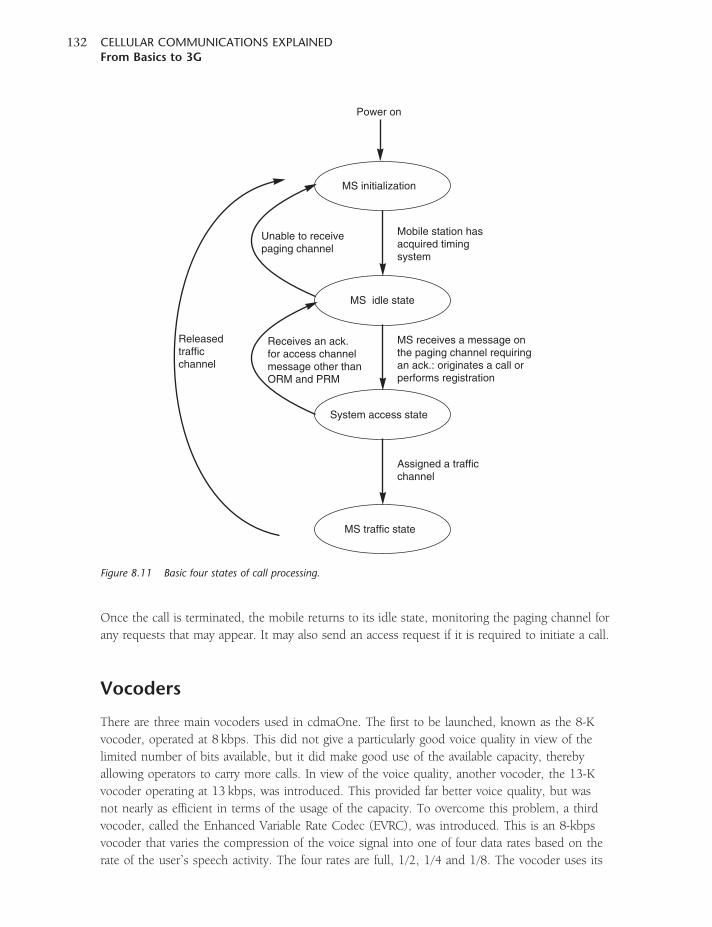
Once the call is terminated, the mobile returns to its idle state, monitoring the paging channel for
any requests that may appear. It may also send an access request if it is required to initiate a call.
Vocoders
There are three main vocoders used in cdmaOne. The first to be launched, known as the 8-K
vocoder, operated at 8 kbps. This did not give a particularly good voice quality in view of the
limited number of bits available, but it did make good use of the available capacity, thereby
allowing operators to carry more calls. In view of the voice quality, another vocoder, the 13-K
vocoder operating at 13 kbps, was introduced. This provided far better voice quality, but was
not nearly as efficient in terms of the usage of the capacity. To overcome this problem, a third
vocoder, called the Enhanced Variable Rate Codec (EVRC), was introduced. This is an 8-kbps
vocoder that varies the compression of the voice signal into one of four data rates based on the
rate of the user’s speech activity. The four rates are full, 1/2, 1/4 and 1/8. The vocoder uses its
MS initialization
MS idle state
System access state
MS traffic state
Mobile station hasacquired timingsystem
Unable to receivepaging channel
Receives an ack.for access channelmessage other thanORM and PRM
Assigned a trafficchannel
MS receives a message onthe paging channel requiringan ack.: originates a call orperforms registration
Releasedtrafficchannel
Power on
Figure 8.11 Basic four states of call processing.
CELLULAR COMMUNICATIONS EXPLAINEDFrom Basics to 3G
132
full rate when a person is talking very fast. It uses the 1/8 rate when the person is silent or nearly
silent. In most areas the 13-K vocoder is the standard, but the originator of the call controls which
vocoder is used.
The vocoder algorithm that is used is Coded Excited Linear Prediction (CELP). The actual specific
algorithm used for cdmaOne is QCELP, a Qualcomm variant of CELP that assists in increasing
the available system capacity.
Two rate-families are currently supported, the first based on 9600 bps and the second on
14 400 bps.
Advantages of CDMA
One of the main advantages claimed for CDMA is a vast improvement in the efficiency of the use of
the spectrum. However, this parameter is very difficult to calculate in real terms, and there are
many claims and counterclaims regarding the measurable advantages. This is because it depends
to a large extent on a variety of aspects, including the level of interference from outside the cell,
the cell density and such like. Accordingly, different methods of calculating the advantages yield
different results. Despite this, some useful comparisons can be made with systems such as GSM.
It is accepted that fifteen voice channels can be placed on each CDMA carrier, and as each carrier
is 1.25MHz wide (1.2288MHz in exact terms), this represents a spectrum usage figure of twelve
voice calls per MHz. GSM can carry eight voice channels per carrier and there are five carriers
per MHz, which appears to provide a usage of forty calls per MHz. However, this is not the full
story because neighbouring cells have to use different frequencies. With a cluster size of twelve
(i.e. twelve cells in a cluster) this figure reduces to 3.3 calls per MHz, although when the
frequency hopping facility of GSM is employed, cluster sizes of seven can be used and the
frequency usage rises to six calls per MHz. Comparing the two systems, when other factors (such as
handoff) that use up some of the capacity of a CDMA system are taken into account, it appears
that cdmaOne has a capacity improvement of around 30 per cent. Whilst much smaller than
the original figures seemed to indicate, it is still very important when the level of calls that can
be carried represents the earnings that can be made by the telephone company, and a figure of
30 per cent is very significant.
Another advantage of CDMA is that new cells can be added relatively easily without the need for
a considerable amount of frequency planning. By adding new cells further capacity is gained, albeit
at the expense of additional interference because there are more mobiles and base stations that can
interfere with one another. Although there is a loss of capacity in each cell, there are more cells and
this brings an overall improvement in capacity – often by as much as fifteen additional channels
for the addition of a new base station. Fortunately, by tailoring the antennas in each base station to
provide the required coverage it is possible to limit the levels of overlap in the cells and thereby
reduce some of the causes of interference.
CHAPTER EIGHTcdmaOne/IS-95
133

9CHAPTER NINE
CDMA2000
With IS-95 established and very successful, it became necessary to upgrade the system with a
high-speed data capability to enable it to carry much faster data and thereby enhance the revenue
growth. The approach adopted by those developing the CDMA technology from cdmaOne/IS-95
was to have a system in which there was a well-defined migration path forward but with full
backward compatibility. As a result of this the IS-2000 standard was developed to enable the higher
3G data rates to be provided.
Within IS-2000, a number of further developments were included. It was envisaged that with many
more areas moving towards 3G standards and the old AMPS systems being made obsolete, it would
be possible to have systems operating on a wider bandwidth. As a result of this, the new standards
allowed for systems that would use the single channel bandwidth (1X) and also ones that would
use three times the bandwidth (3X).
The first stage of the 3G development in the form of CDMA2000 1X can double the voice capacity
of cdmaOne networks and deliver peak packet data speeds of 307 kbps in mobile environments.
CDMA2000 1X has been designated a 3G standard, and is widely deployed with operators in all
continents of the world. Like cdmaOne, 1X is widely deployed in North America and the
Asia Pacific regions as well as many other countries around the globe.
CDMA2000 1X is the basic 3G standard but, in what is termed CDMA2000 1xEv, there are further
developments. The first of these, known as CDMA2000 1xEV-DO (evolution data only or, as it is
becoming more widely known, EVolution Data Optimized) is something of a sideline from the
main evolutionary development of the standard. It is defined under IS-856 rather than IS-2000 and,
as the name indicates, it carries only data, but at speeds up to 3.1Mbps in the forward direction
and 1.8Mbps in the reverse direction, the speed in the reverse link being upgraded as part of
Release A of the standard. The first commercial CDMA2000 1xEV-DO network was deployed by
SK Telecom (Korea) in January 2002 (see Figure 9.1).
The next logical evolution of the system is to incorporate both data and voice into the standard.
This is exactly what CDMA2000 1xEV-DV achieves. This is catered for under Release C of the
IS-2000 standard, and is effectively 1X with additional high-speed data channels. In this way it
is able to provide complete backward compatibility with both CDMA2000 1X and cdmaOne.
In addition to this, the migration requires comparatively few upgrades to a 1X system and as such
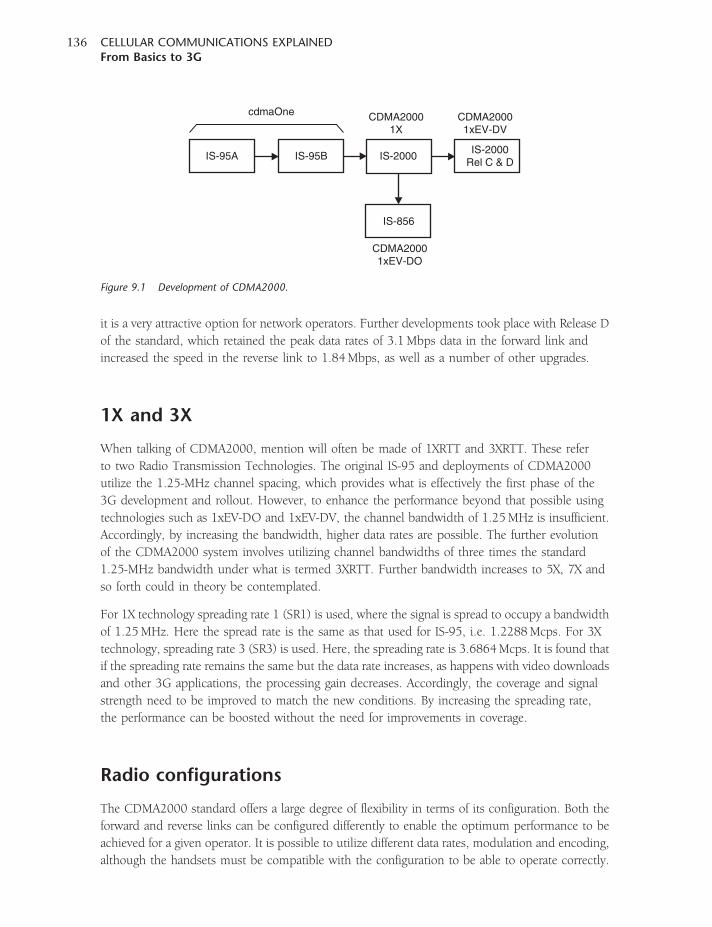
it is a very attractive option for network operators. Further developments took place with Release D
of the standard, which retained the peak data rates of 3.1Mbps data in the forward link and
increased the speed in the reverse link to 1.84Mbps, as well as a number of other upgrades.
1X and 3X
When talking of CDMA2000, mention will often be made of 1XRTT and 3XRTT. These refer
to two Radio Transmission Technologies. The original IS-95 and deployments of CDMA2000
utilize the 1.25-MHz channel spacing, which provides what is effectively the first phase of the
3G development and rollout. However, to enhance the performance beyond that possible using
technologies such as 1xEV-DO and 1xEV-DV, the channel bandwidth of 1.25MHz is insufficient.
Accordingly, by increasing the bandwidth, higher data rates are possible. The further evolution
of the CDMA2000 system involves utilizing channel bandwidths of three times the standard
1.25-MHz bandwidth under what is termed 3XRTT. Further bandwidth increases to 5X, 7X and
so forth could in theory be contemplated.
For 1X technology spreading rate 1 (SR1) is used, where the signal is spread to occupy a bandwidth
of 1.25MHz. Here the spread rate is the same as that used for IS-95, i.e. 1.2288Mcps. For 3X
technology, spreading rate 3 (SR3) is used. Here, the spreading rate is 3.6864Mcps. It is found that
if the spreading rate remains the same but the data rate increases, as happens with video downloads
and other 3G applications, the processing gain decreases. Accordingly, the coverage and signal
strength need to be improved to match the new conditions. By increasing the spreading rate,
the performance can be boosted without the need for improvements in coverage.
Radio configurations
The CDMA2000 standard offers a large degree of flexibility in terms of its configuration. Both the
forward and reverse links can be configured differently to enable the optimum performance to be
achieved for a given operator. It is possible to utilize different data rates, modulation and encoding,
although the handsets must be compatible with the configuration to be able to operate correctly.
IS-95A IS-95B IS-2000IS-2000
Rel C & D
IS-856
cdmaOne CDMA20001X
CDMA20001xEV-DV
CDMA20001xEV-DO
Figure 9.1 Development of CDMA2000.
CELLULAR COMMUNICATIONS EXPLAINEDFrom Basics to 3G
136
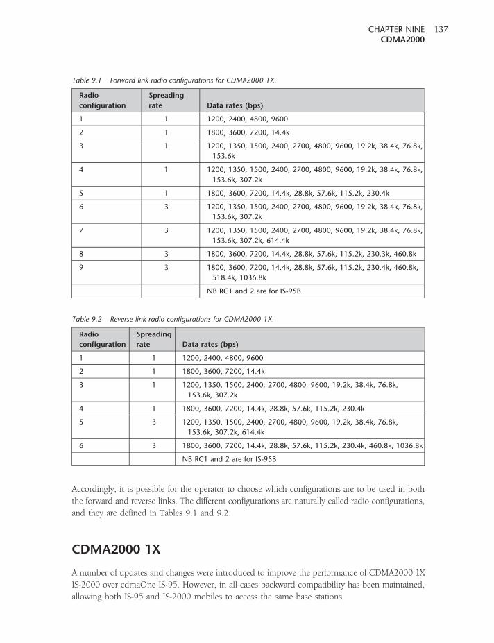
Accordingly, it is possible for the operator to choose which configurations are to be used in both
the forward and reverse links. The different configurations are naturally called radio configurations,
and they are defined in Tables 9.1 and 9.2.
CDMA2000 1X
A number of updates and changes were introduced to improve the performance of CDMA2000 1X
IS-2000 over cdmaOne IS-95. However, in all cases backward compatibility has been maintained,
allowing both IS-95 and IS-2000 mobiles to access the same base stations.
Table 9.1 Forward link radio configurations for CDMA2000 1X.
Radio
configuration
Spreading
rate Data rates (bps)
1 1 1200, 2400, 4800, 9600
2 1 1800, 3600, 7200, 14.4k
3 1 1200, 1350, 1500, 2400, 2700, 4800, 9600, 19.2k, 38.4k, 76.8k,
153.6k
4 1 1200, 1350, 1500, 2400, 2700, 4800, 9600, 19.2k, 38.4k, 76.8k,
153.6k, 307.2k
5 1 1800, 3600, 7200, 14.4k, 28.8k, 57.6k, 115.2k, 230.4k
6 3 1200, 1350, 1500, 2400, 2700, 4800, 9600, 19.2k, 38.4k, 76.8k,
153.6k, 307.2k
7 3 1200, 1350, 1500, 2400, 2700, 4800, 9600, 19.2k, 38.4k, 76.8k,
153.6k, 307.2k, 614.4k
8 3 1800, 3600, 7200, 14.4k, 28.8k, 57.6k, 115.2k, 230.3k, 460.8k
9 3 1800, 3600, 7200, 14.4k, 28.8k, 57.6k, 115.2k, 230.4k, 460.8k,
518.4k, 1036.8k
NB RC1 and 2 are for IS-95B
Table 9.2 Reverse link radio configurations for CDMA2000 1X.
Radio
configuration
Spreading
rate Data rates (bps)
1 1 1200, 2400, 4800, 9600
2 1 1800, 3600, 7200, 14.4k
3 1 1200, 1350, 1500, 2400, 2700, 4800, 9600, 19.2k, 38.4k, 76.8k,
153.6k, 307.2k
4 1 1800, 3600, 7200, 14.4k, 28.8k, 57.6k, 115.2k, 230.4k
5 3 1200, 1350, 1500, 2400, 2700, 4800, 9600, 19.2k, 38.4k, 76.8k,
153.6k, 307.2k, 614.4k
6 3 1800, 3600, 7200, 14.4k, 28.8k, 57.6k, 115.2k, 230.4k, 460.8k, 1036.8k
NB RC1 and 2 are for IS-95B
CHAPTER NINECDMA2000
137
For IS-2000, CDMA2000 1X, several new methods of coding and spreading are used, and these
enable much higher capacities to be achieved. The first major change is that the Walsh codes used
are a different length. For IS-95, the length of the code was 64 bits and there was a choice of 64
codes per carrier. For 1X, the codes are generally 128 bits long, allowing for a total of 128 different
codes. In addition to this, CDMA2000 uses stronger error coding functions and also turbo-codes
rather than the convolutional codes used for IS-95. This enables higher-speed data to be sent.
In addition to this, interleaving and symbol repetition are used to provide the various data rates.
Turbo-codes are a class of error correction codes that enable transfer rates over a noisy channel to
approach the ‘Shannon’ limit. The turbo-coding principle was first proposed in 1993 by Professors
Claude Berrou and Alain Glaxieux. Originally their claims that the codes could double throughput
for a given power were treated with scepticism, but their findings were eventually proved to be
accurate. Turbo-coders use powerful interleavers that reduce the susceptibility of a data stream to
random and impulsive noise. By working on ‘soft’ bits from a radio receiver, the turbo-codes enable
the decoder to extract the maximum level of data from the noisy signals. Turbo-codes require two
encoders and two decoders per link, and these blocks operate in parallel and work synergistically.
They also use an iterative process to reduce the amount of processing required, but despite this
they still require more processing power than previous coding systems such as convolutional codes.
Apart from the improvements in the spreading and channel generation, there are also changes in
the air interface itself. The IS-95 forward link uses a form of QPSK where the data on both the I and
Q channels are the same. However, for CDMA2000 the I and Q channels are different, and this
gives the advantage that half the bandwidth can be used for the same number of chips, or twice the
number of chips can be sent in the same bandwidth. While this does make the reception more
sensitive to phase errors, other improvements (including an improved system of forward power
control and forward transmit diversity) enable these problems to be overcome to a sufficient degree,
thereby effecting a doubling of the spectrum usage efficiency.
Similarly, there are significant changes on the reverse link where several new channels have been
added. These include a pilot channel, as well as supplemental data channels and a control channel
for signalling. Additionally, similar to the forward link, the reverse link now uses Walsh codes
to differentiate between the different channels. A further change is that the format of the carrier
modulation is changed. With the reverse link now transmitting multiple channels, the use of
OQPSK would not prevent zero crossings. To achieve this, the modulation format is changed to
a scheme known as Orthogonal Complex Quadrature Phase Shift Keying (OCQPSK). This form of
modulation requires a number of stages. First the channels to be transmitted are split so that some
take the I path and others the Q path, and then they are scrambled along with the Walsh code
spreading. In the scrambling process the probability of zero crossings is identified and, using
a scheme known as Orthogonal Variable Spreading Function (OVSF), the probability of zero
crossings is reduced. Accordingly, the channels are spread with a Walsh code sequence and
summed with the correct gain to produce the I and Q sequences. These are then further spread
by a long PN code with its mobile-specific long mask to identify the mobile, and these I and Q
sequences are modulated onto the carrier. Although particularly complicated, this form of
modulation does have fewer zero crossings and the power amplifier in the mobile does not have to
be run in a linear mode, thereby saving battery power.
CELLULAR COMMUNICATIONS EXPLAINEDFrom Basics to 3G
138
Power control
For IS-95, fast power control was implemented on the reverse link to ensure that all the mobiles
could be received at virtually the same power level. This is achieved by using a power control
message every 1.25ms. In this way, the ‘near–far’ problem could be overcome. However, on the
forward link, where power control was not as critical, a power control message was sent every
20ms to adjust the channel power to a given mobile.
While in many respects power control may not be quite as critical in the forward direction, when
high data speeds are being carried accurate power control becomes more of an issue. Accordingly,
a scheme similar to that implemented on the reverse link has been introduced on the forward link.
It involves the use of two loops, as on the reverse link. The outer loop sets the required Eb /N0 (this
is effectively a measurement of signal-to-noise ratio, where it is the energy per bit divided by the
noise power spectral density, to ensure a given acceptable frame error rate (FER). The inner loop
then measures the received signal-to-noise ratio, and sends control bits back to the base station via
the power control sub-channel on the new reverse pilot channel. In this way, power control is
implemented every 1.25ms as on the forward link.
Improvements have also been made to the reverse link power control. In view of the impact on
high data-rate transmissions, the control can be implemented in 0.25-dB steps.
Beam formatting
The CDMA2000 system has been planned to accommodate smart antenna systems that allow
beam formatting. Although advanced in concept, this technique has been in the minds of cellular
and other wireless communications systems designers for many years. By adopting this technique,
much smaller beams can be realized. This has the same effect as using smaller cells, and allows the
re-use of the same codes more often. It also reduces the levels of interference, thereby allowing the
full potential of the system to be realized and the highest data rates to be achieved.
In consequence, a number of new channels have been introduced to cater for this when it is
implemented. For example, the primary pilot channel is used for the mobile to synchronize with
the cell, and then an auxiliary pilot channel is used to allow it to synchronize to a specific beam.
Channels
CDMA2000 builds on IS-95 cdmaOne, and as a result it utilizes many of the channels that were
found on the original system. However, in order to be able to provide the additional functionality
and performance, a number of new channels have been incorporated. Channels are different for the
forward and reverse links.
Forward link channels
1. Forward Pilot Channel (F-PICH). This remains the same as it was on IS-95. It carries no data,
and uses Walsh code 0. As Walsh code 0 is used, this is all zeros and therefore its length is
immaterial; thus it retains compatibility with IS-95.
CHAPTER NINECDMA2000
139
2. Forward Transmit Diversity Pilot Channel (F-TDPICH). While the F-PICH channel remains
the primary pilot channel, this channel is used to provide a pilot for transmit diversity when
two antennas are used. It provides a timing reference for the second antenna diversity signals.
As F-PICH is the primary channel, this one is normally set at a power level below it.
3. Forward Dedicated Auxiliary Pilot Channel (F-APICH). This channel is used when smart antennas
are employed. Under these circumstances a sector can be further divided into smaller sector
beams, and this can be used to reduce the levels of interference. When this is implemented,
each of these beams forms a new sector and needs its own pilot channel.
4. Forward Auxiliary Transmit Diversity Pilot Channel (F-ATDPICH). This channel is required when
transmitting diversity in each beam when using a smart antenna system.
5. Forward Sync Channel (F-SYNCH). This channel provides the same functionality and operates in
the same fashion as for IS-95. The timing of the channel is also aligned with that of the pilot
channel, and as a result the mobile is able easily to decode the sync channel messages. Some
additional information does need to be transmitted on this channel. For example, it is necessary
to inform the mobile whether the base station is 1X or 3X compatible.
6. Forward Paging Channel (F-PCH). This channel retains the same structure as that used for IS-95,
but a number of enhancements have been introduced. Information such as overhead and
direction messages to specific mobiles can now be transmitted on other channels, and this
improves the performance of the channel. Improvements have also been made to the sleep
mode, so messages can be handled by a variety of channels when the mobile is not engaged in a
call. These include the following:
� Forward Quick Paging Channel (F-QPCH). This channel provides information to the
mobile so that it can use slotted reception for its sleep mode. For IS-95, the mobile awoke
at specific times to check the paging channel, which also carried other information. The
forward quick paging channel is dedicated to this function, and is able to perform it more
effectively. Using the paging channel in IS-95 the receiver had to wake up and receive a
96-ms slot, whereas using the F-QPCH it only needs to wake up and receive a 5-ms slot.
This gives a significant reduction in the time for which the receiver needs to be awake, and
considerably extends the standby battery life.
� Forward Common Control Channel (F-CCCH). The F-CCCH is a forward link channel that
transmits control information to a specific mobile. The frame sizes for this channel may be
5, 10 or 20ms, and these provide data rates of 9.6, 19.2 and 38.4 kbps, respectively. When
not on a call, mobile-specific messages can be sent on the F-CCCH.
� Forward Broadcast Control Channel (F-BCCH). This channel is used to broadcast messages
to all mobiles within the coverage area of the cell. These messages may include
advertisements of news as well as static paging messages. The channel transmits data at 4.8,
9.6 or 19.2 kbps.
7. Forward Common Power Control Channel (F-CPCCH). Even when it is not involved in a call,
the mobile still needs to receive bits for its power control. Each mobile therefore monitors
a particular bit in this channel to enable it to adjust its power up or down by one increment.
CELLULAR COMMUNICATIONS EXPLAINEDFrom Basics to 3G
140
To ensure the maximum speed, this information is not encoded. If any data errors are
introduced, the error is quickly corrected by the next bit.
8. Forward Fundamental Channel (F-FCH). This channel is still the main channel to carry the
payload, whether voice or data. The fundamental channel uses a fixed amount of spreading,
and the variable data rates are achieved by using symbol repetition.
9. Forward Supplemental Code Channel (F-SCCH). The supplemental code channels are retained
from IS-95 and contained within a traffic channel, and they are used to carry or data but may
only be used with RC1 and RC2. For RC1 the frame size is 20ms and the data rate is 9.6 kbps,
whereas for RC2 the data rate is 14.4 kbps.
10. Forward Supplemental Channel (F-SCH). This channel is contained within the traffic channel,
and can only be used with radio configurations 3 to 5 for 1X and 6 to 9 for 3X. The channel
can use variable length Walsh codes to provide a constant spreading rate. It provides for a wide
range of data rates, from 1200 bps right up to 1 036 800 bps.
11. Forward Dedicated Control Channel (F-DCCH). This channel carries information from the base
station to the mobile. For IS-95 systems, the control information was sent on the forward
traffic channel along with the voice data during a call. The introduction of this channel for
CDMA2000 removes the requirement from the traffic channel to carry control information,
thereby allowing the traffic channel to carry the data for which it was primarily intended and
thus improving its efficiency.
Reverse channels
A number of improvements and new channels have been applied to the reverse link as well,
including the following:
1. Reverse Pilot Channel (R-PICH). This new channel for CDMA2000 provides a reference for base
stations to gain initial access to a system and channel recovery. The channel also carries power
control information for the forward link. Although the addition of this channel results in
increased battery consumption, it provides significant advantages and has therefore been
incorporated into the system.
2. Reverse Access Channel (R-ACH). This channel operates in the same manner as that used for
IS-95 and provides backward compatibility. It is used by the mobile to transmit random bursts
when it attempts to access the system.
3. Reverse Enhanced Access Channel (R-EACH). The reverse enhanced access channel performs the
same functions as R-ACH, but has been enhanced to provide improved methods of access.
There are two modes in which it can operate. The first is what is termed a basic access mode,
where the channel carries access messages in a similar manner to that used on IS-95. The
second is termed a reservation access mode, and it is used to reserve radio resources such as
Internet access, etc. In both of these modes the channel is only used to establish the
communications access. It can have frame sizes of 5, 10 and 20ms, and provides data
transmission at speeds of 9.6, 19.2 and 38.4 kbps.
4. Reverse Common Control Channel (R-CCCH). This channel is an access channel that enables
CDMA2000 to provide improved packet access. It provides the much faster access and lower
CHAPTER NINECDMA2000
141
latency required for packet access. It offers a 20-ms 9.6-kbps channel, and in addition to this
there are new 5- and 10-ms frames that offer data rates of 19.2 and 38.4 kbps, respectively.
In operation, this channel is controlled by a closed-loop power control system.
5. Reverse Dedicated Control Channel (R-DCCH). This is similar to the F-DCCH, and is used to
carry signalling and user information in a call. The channel is only present if there are data to
be transmitted.
6. Reverse Fundamental Channel (R-FCH). This is the channel in the reverse link that is used
to carry the voice and data payload. It allows for either 5- or 20-ms frames; the shorter
frames are used to give lower latency (i.e. the phone gets the data it needs in 5ms rather
than 20ms).
7. Reverse Supplemental Code Channel (R-SCCH). This channel is the equivalent of the F-SCCH
and is used with radio configurations 1 and 2. Again, the timing of this channel is offset
from the fundamental channel by 1.25mS. There can be up to seven used per traffic channel.
8. Reverse Supplemental Channel (R-SCH). The reverse supplemental channel provides user data
rates that vary from as low as 1200 bps up to 230.4 kbps (and 103.68 kbps for 3X). To
accomplish this, the channel uses variable length Walsh codes. This channel applies only to
radio configurations 3 and 4 for 1X, and 5 and 6 for 3X.
Packet data
With a growing level of data being sent, the packet data system has been adopted for this rather
than circuit switched data, as it allows for far more efficient use of the data channels and therefore
many users to access the capacity. This is particularly useful because much data is ‘bursty’ in
nature, and circuit switching will tie up capacity even when no data are actually being sent.
Accordingly, packet data can be sent easily over CDMA2000, where a slotted Aloha principle
is used. Instead of using a fixed transmission power, it increases the transmission power for the
random access burst after an unsuccessful access attempt. Then, after the mobile station has
been allocated a traffic channel, it can transmit without scheduling up to a predefined bit rate.
If the transmission rate exceeds the defined rate, a new access request has to be made.
When the mobile station stops transmitting, it releases the traffic channel but not the dedicated
control channel. After a while it also releases the dedicated control channel, but maintains the link
layer and network layer connections in order to shorten the channel set-up time when new data
need to be transmitted. Short data bursts can be transmitted over a common traffic channel in
which a simple ARQ is used to improve the error rate performance.
Handoff
One of the main limiting factors with IS-95 was the handoff process. With the ease with which
soft handoffs could be performed, they occurred very frequently. This actually took up a
considerable amount of the radio capacity, and in many instances it limited the capacity of the
system. When developing CDMA2000, it was necessary to ensure that this problem did not
occur again.
CELLULAR COMMUNICATIONS EXPLAINEDFrom Basics to 3G
142
To achieve the required improvement, a number of measures were taken. A number of thresholds
were introduced to determine whether a handoff is really necessary. These are based on elements
such as the total pilot channel energy that is coherently demodulated. By utilizing the thresholds,
the number of handoffs is reduced while still ensuring that handoffs are implemented when they
are really required. By achieving a reduction in the number of handoffs that are undertaken, the
system capacity that is available for real traffic is increased.
CDMA2000 1xEV-DV
While CDMA2000 1X was particularly successful, and the data rates offered did fall into some
of the 3G classifications, it was nonetheless not the final evolution for 1X. Higher data rates
were needed to retain users, and the IS-2000 standard was updated to accommodate this.
As defined in Figure 9.1, it can be seen that Releases A and B of the standard catered for just
the 1X capability, whereas the EV-DV capability was introduced in Release C and then upgraded
in Release D.
The key features of CDMA2000 1xEV-DV are a high forward link capacity with data rates up to
3.1Mbps peak with an average sector throughput of 1Mbps. The original Release C version of the
IS-2000 specification provided only for data rates of 384 kbps in the reverse direction, as it was
anticipated that most of the data flow would be in the forward link. However, with applications
such as video-conferencing becoming more likely, the Release D specification increased the
maximum data rate in the reverse link to 1.8456Mbps.
A further feature of the evolution was to provide concurrent support for both data and voice. This
provides operators with an efficient use of their available spectrum as separate channels are not
required for data and voice. The concept is that by taking advantage of the different usage patterns
of voice and data, it is possible for the operator to make the most efficient use of the available
spectrum. A further requirement of 1xEV-DV is that it retains backward compatibility with 1X and
also with IS-95.
Despite the advantages of the scheme and its complete backward compatibility, many
operators are adopting the 1xEV-DO solution for data, described below. Although this
requires a separate 1X channel if voice traffic is to be carried (other than by Voice over IP),
the data elements of the system have been optimized, and the industry appears to be
moving toward the EV-DO standard. Nevertheless, an overview of the EV-DV solution is
provided here.
New features
In order to meet the requirements for 1xEV-DV, a number of new features needed to be
implemented. These included the addition of new channels and an adaptive modulation
and coding scheme, and the addition of ARQ (Automatic Repeat reQuest – a mechanism
used to trigger the retransmission of data packets received in error) to the physical layer and
cell switching.
CHAPTER NINECDMA2000
143
New channels
The EV-DV specification utilizes one new traffic channel and three new control channels as follows:
1. Forward Packet Data Channel (F-PDCH). This is the main packet data channel. There can be
two per sector, users being separated by both code-division and time-division techniques.
The channel carries data, as well as some layer 3 signalling. To achieve the high data rate
required, adaptive modulation and hybrid ARQ are applied.
2. Forward Packet Data Control Channel (F-PDCCH). This channel is a forward link control
channel, and it provides the mobile with the information it needs to correctly identify
data intended for it on the F-PDCH. In more specific terms, the information carried is the
MAC-ID, the F-PDCH packet size, the number of slots per sub-packet and the last Walsh
code index. The MAC-ID is an 8-bit identifier known by the mobile and base station. It
signifies the data being carried on the F-PDCH that is destined for the mobile. This
identifier is set up as part of the call set-up procedure, and it remains the same during the
duration of the call. The F-PDCH packet size simply indicates the size of the packet being
transmitted, and the number of slots informs the mobile of the number of time division slots
it occupies. The last Walsh code index is used by the mobile to determine the number of
Walsh codes used for the data transmission on the F-PDCH to allow code division multiplexing
on the channel.
3. Reverse Channel Quality Indicator Channel (R-CQICH). This channel is used for the mobile to
report the results of measurements of the channel quality of the best serving sector back to the
base station.
4. Reverse Acknowledgement Channel (R-ACKCH). This channel is used to inform the base station
whether or not a packet transmitted on the F-PDCH has been successfully received.
Tables 9.3 and 9.4 show the channel types on forward and reverse CDMA links, respectively, for
spreading rate 1.
Adaptive modulation
CDMA2000 1xEV-DV supports much higher levels of data throughput than does the 1X service.
One of the key elements in being able to achieve this is the fact that adaptive modulation and
coding is used. This is able to modify the RF transmission to best adapt to the environment
and signal path that exists between the transmitter and the receiver (i.e. the base station and
the mobile) or vice versa.
The adaptation is achieved by varying the RF packet duration, the number of bits
per packet and the coding algorithm. The RF packet duration can be 1.25, 2.5 or 5ms,
and the number of bits per packet varies from 408 to 3864 bits. It will be seen that the
variation in the number of bits per packet varies over a wider range than the packet length;
this is achieved by also changing the modulation type, using QPSK, 8-PSK or 16 QAM. By
making a choice from all these elements, it is possible to make the best utilization of the
carrier.
CELLULAR COMMUNICATIONS EXPLAINEDFrom Basics to 3G
144
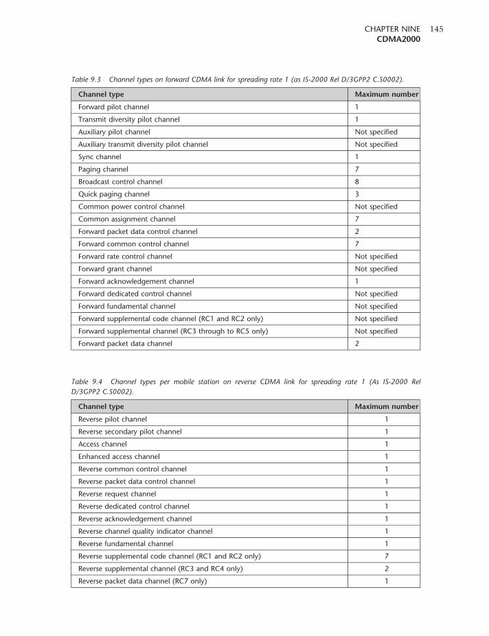
Table 9.3 Channel types on forward CDMA link for spreading rate 1 (as IS-2000 Rel D/3GPP2 C.S0002).
Channel type Maximum number
Forward pilot channel 1
Transmit diversity pilot channel 1
Auxiliary pilot channel Not specified
Auxiliary transmit diversity pilot channel Not specified
Sync channel 1
Paging channel 7
Broadcast control channel 8
Quick paging channel 3
Common power control channel Not specified
Common assignment channel 7
Forward packet data control channel 2
Forward common control channel 7
Forward rate control channel Not specified
Forward grant channel Not specified
Forward acknowledgement channel 1
Forward dedicated control channel Not specified
Forward fundamental channel Not specified
Forward supplemental code channel (RC1 and RC2 only) Not specified
Forward supplemental channel (RC3 through to RC5 only) Not specified
Forward packet data channel 2
Table 9.4 Channel types per mobile station on reverse CDMA link for spreading rate 1 (As IS-2000 Rel
D/3GPP2 C.S0002).
Channel type Maximum number
Reverse pilot channel 1
Reverse secondary pilot channel 1
Access channel 1
Enhanced access channel 1
Reverse common control channel 1
Reverse packet data control channel 1
Reverse request channel 1
Reverse dedicated control channel 1
Reverse acknowledgement channel 1
Reverse channel quality indicator channel 1
Reverse fundamental channel 1
Reverse supplemental code channel (RC1 and RC2 only) 7
Reverse supplemental channel (RC3 and RC4 only) 2
Reverse packet data channel (RC7 only) 1
CHAPTER NINECDMA2000
145
Hybrid automatic repeat request
In order to maintain the high data transmission rates of 1xEV-DV, it is necessary to ensure the fast
re-transmission of any packets received with errors. As a result, the Automatic Repeat Request
(ARQ) has been migrated from the MAC layer to the physical layer. Hybrid ARQ (HARQ) then
improves the throughput by combining, rather than discarding, those packets that failed with the
current attempt. In this way it is able more quickly and accurately to receive the data and re-build it
if necessary. By adopting HARQ, which acts in the physical layer, shorter round trip delays are
experienced compared to those using higher layer retransmission schemes employed in the Radio
Link Protocol (RLP). This considerably reduces the possibility of data session timeout when using
protocols such as TCP/IP. Additionally, it reduces latency, increases the average throughput and is
more spectrally efficient.
Base station selection
When selecting a cell, the mobile will make RF quality measurements to enable it to connect to the
base station providing the best RF link quality. Using a scheme known as cell selection, no soft
handoff is undertaken for the EV-DV channels, although it is still active for the CDMA2000 1X
traffic. By adopting this approach, the large overhead on the network resources caused by soft
handoff is greatly reduced.
The system of cell selection requires that the base stations synchronize the F-PDCH data stream
since it is possible that the mobile will have channels belonging to multiple base stations in its
active set. When selecting a base station, the mobile indicates this selection via R-CQICH; the
network receives this message and transmits the 1xEV-DV forward link data via the relevant
base station.
Release D
The initial release of the IS-2000 specification defining 1xEV-DV appeared in the release C version
of the specification. Further updates were undertaken to increase the speed of the reverse link to
provide data at a much increased speed, as well as providing some improvements for the forward
link as well.
To achieve the increased reverse link data transfer rates, new channels were introduced as follows:
1. Reverse Packet Data Channel (R-PDCH). This is a data bearing channel in the reverse link; it has a
fixed duration of 10ms and it can only transmit any of the fixed packet sizes of length 192, 408,
792, 1560, 3096, 4632, 6168, 9240, 12 312, 15 384 or 18 432 bits. Using the variable packet
sizes, four channel HARQ and a maximum of three transmissions enable data rates from
6.4 kbps right up to 1.8432Mbps to be achieved.
2. Reverse Packet Data Control Channel (R-PDCCH). This channel was introduced to avoid the
problem of blind detection and decoding at the base station, and the channel carries
information relating to the packet format on the R-PDCH.
3. Reverse Request Channel (R-REQCH). This channel supports the autonomous transmission
mode, permitting the mobile to start transmission at any given time up to a pre-authorized
CELLULAR COMMUNICATIONS EXPLAINEDFrom Basics to 3G
146
maximum data rate. The autonomous mode allows the mobile to start up a service at
any time while simultaneously reducing the delay. In this way the system is able to provide
different levels of quality of service, to enable it to meet the needs of the mobile more
accurately.
4. Reverse Secondary Pilot Channel (R-SPICH). This channel serves three purposes: to facilitate fast
and simple detection, to improve reverse link power control, and to improve the coherent
demodulation.
Further channels were also introduced in the forward link:
1. Forward Grant Channel (F-GCH). This channel is monitored by all mobiles within the
sector served by the channel. It is used when high-speed data transmissions are to
be undertaken, and it allows a mobile access to the network for data transmission above
a given rate.
2. Forward Indicator Control Channel (F-ICCH). This was added to facilitate rate control on a
per user or per sector basis.
3. Forward Acknowledgement Channel (F-ACKCH). This channel provides synchronous acknowl-
edgements to the received reverse link data packet transmissions. The channel is capable of
serving up to 192 users in any given sector.
Broadcast and multicast services
In addition to the fast data in both forward and reverse links, EV-DV is also able to support
broadcast multimedia transmissions from a single source to multiple users with users in either an
active or an idle state. This is achieved by enhancing the forward supplemental channel and the
forward fundamental channel, and this can be achieved in one of three ways.
In the first approach, the F-SCH channel is shared among the idle mobile stations and no reverse
link channels are required. To enable the service to operate, new Broadcast and Multicast Services
(BCMCS) specific upper layer messages are sent to the mobiles with parameters for configuration
information. Handoff is autonomous, the mobile selecting the best base station from which to
receive the data.
For the second type of BCMCS, the F-FCH is shared among the active mobiles. When a
mobile is in a traffic state, the F-FCH can be shared and used to carry BCMCS content. For this
type, the F-CPCCH carries the power control command and the F-DCCH carries the individual
signalling, using a TDM approach for each mobile. Each mobile has its own long code mask for
reverse link channelization. Using this mode, data rates of 9.6 and 14.4 kbps are supported. The
advantage of this type of BCMCS is that it provides dynamic coverage and optimizes base station
power usage and code usage. Additionally, it allows soft handoff.
The third type of BCMCS shares the F-SCH among the active mobile stations, and it can be used by
mobiles in a traffic state. The F-SCH is shared by all users. Signalling procedures remain the same
for the shared F-SCH.
CHAPTER NINECDMA2000
147
Fast call set-up
With any cellular communications system, call set-up can take a while. For CDMA2000, it can take
up to 12 seconds under worst-case scenarios. This length of time is unacceptable for applications
such as Push to talk over Cellular (PoC). Much of the delay arises from the procedures that have to
be undertaken. A call set-up can be split into three stages: paging, access, and channel set-up and
service negotiation.
To reduce the time for fast call set-up, a number of measures have been taken. The first is to reduce
the paging delay. When an application such as PoC is encountered, the mobile may enter a
reduced slotted or a non-slotted mode for a period of time. This decreases the time between paging
slots, and may reduce the paging time by several seconds. Additionally, the base station may
perform channel assignment without the access procedure, again saving several seconds. Finally,
the traffic channel set-up has been simplified, thereby saving time. Combined, these measures
enable very fast call set-up to be achieved when it is required.
Mobile equipment identifier
Mobile phones are assigned a 32-bit Electronic Serial Number (ESN). However, with the enormous
growth in mobile phone production these numbers are running out. To resolve the problem, a
56-bit identifier known as the Mobile Equipment Identifier (MEID) has been introduced. Careful
implementation has been required to ensure that both ESNs and MEIDs can operate alongside each
other. Having overcome these problems, this has enabled a much greater number of identification
serial numbers to be used, preventing the shortage that was due to occur.
CDMA2000 1xEV-DO
Despite the fact that EV-DO may be considered something of a sidetrack from the main IS-2000
development, it has nevertheless gained significant acceptance and now appears to be the main
route to provide 3G data speeds. As the name implies, it has been optimized for data transmission,
the letters now standing for ‘data optimized’ rather than the initial meaning of ‘data only’.
However, being a data-only system, channels that carry DO transmissions may not carry voice.
A separate 1X carrier is required for voice transmissions unless they are carried, for example, as data
in the form of Voice over IP (VoIP).
The CDMA2000 1xEV-DO cell phone system is defined under IS-856 rather than IS-2000, which
defines the other CDMA2000 standards. In Release 0 of the standard, the maximum data rate was
2.4576Mbps in the forward (downlink) with 153.6 kbps in the reverse (uplink) direction – the
same as CDMA2000 1X. However, in a later release of the standard, Release A, the forward data rate
has risen to 3.072Mbps and the reverse data rate to 1.8432Mbps (see Figure 9.2).
The forward channel forms a dedicated variable-rate packet data channel with signalling and control
time multiplexed into it. The channel is itself time-divided and allocated to each user on a demand
and opportunity driven basis. A data-only format was adopted to enable the standard to be
CELLULAR COMMUNICATIONS EXPLAINEDFrom Basics to 3G
148
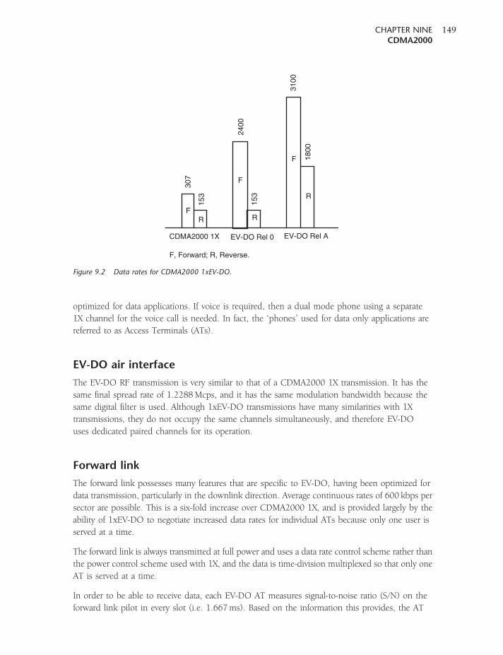
optimized for data applications. If voice is required, then a dual mode phone using a separate
1X channel for the voice call is needed. In fact, the ‘phones’ used for data only applications are
referred to as Access Terminals (ATs).
EV-DO air interface
The EV-DO RF transmission is very similar to that of a CDMA2000 1X transmission. It has the
same final spread rate of 1.2288Mcps, and it has the same modulation bandwidth because the
same digital filter is used. Although 1xEV-DO transmissions have many similarities with 1X
transmissions, they do not occupy the same channels simultaneously, and therefore EV-DO
uses dedicated paired channels for its operation.
Forward link
The forward link possesses many features that are specific to EV-DO, having been optimized for
data transmission, particularly in the downlink direction. Average continuous rates of 600 kbps per
sector are possible. This is a six-fold increase over CDMA2000 1X, and is provided largely by the
ability of 1xEV-DO to negotiate increased data rates for individual ATs because only one user is
served at a time.
The forward link is always transmitted at full power and uses a data rate control scheme rather than
the power control scheme used with 1X, and the data is time-division multiplexed so that only one
AT is served at a time.
In order to be able to receive data, each EV-DO AT measures signal-to-noise ratio (S/N) on the
forward link pilot in every slot (i.e. 1.667ms). Based on the information this provides, the AT
307
153
153
2400
3100
1800
FR
F
R
F
R
F, Forward; R, Reverse.
CDMA2000 1X EV-DO Rel 0 EV-DO Rel A
Figure 9.2 Data rates for CDMA2000 1xEV-DO.
CHAPTER NINECDMA2000
149
sends a data rate request to the base station or Access Node (AN). The AN receives requests
from a variety of ATs, and decisions have to be made regarding which ATs are to be served next.
The AN endeavours to achieve the best data transfer, and this is done by serving those ATs offering
a good signal-to-noise ratio. This is achieved at the expense of users experiencing poor propagation
conditions, which will typically be those at some distance from the AN’s antenna.
As with 1X, accurate time synchronization is required between the EV-DO access nodes. To achieve
this, time information is taken from the Global Positioning System, as this is able to provide an
exceedingly accurate time signal.
Forward link channels
A number of channels are transmitted in the forward direction to enable signalling, data and other
capabilities to be handled. These channels include the traffic, MAC, control and pilot channels.
These are time-division multiplexed.
1. Traffic channel. This channel uses quadrature phase shift keying (QPSK) modulation for data
rates up to 1.2288Mbps. For higher data rates higher-order modulation techniques are used,
in the form of 8PSK with 3 bits per symbol or 16QAM with 4 bits per symbol. The levels
of the I and Q symbols are chosen so that the average power remains the same regardless
of the modulation scheme employed. The incoming data to be used in the modulation come
from the turbo-coder, and are scrambled by mixing with a pseudorandom number (PN)
sequence. The initial state of the PN is derived from known parameters, and is unique for each
user. Every packet starts at the same initial value of the PN sequence. At the beginning of the
transmission to each user, there is a preamble that contains the user ID for the data. Its repeat
rate is determined by the data rate because lower data rates require higher repeat values.
However, even at its largest the preamble will fill no more than half the first slot.
2. Control channel. This channel carries the signalling and overhead messages. It has the same
structure as the traffic channel.
3. Pilot channel. The differentiator between the cell and the sector is still the PN offset of the pilot
channel, and the pilot signal is only gated on for 192 chips per slot. The pilot PN sequence is
the time-reversed sequence of 1X. This is done so that mobiles do not confuse 1X transmissions
with EV-DO ones.
4. Medium Access Control (MAC) channel. This channel carries a number of controls, including
the Reverse Power Control (RPC), the Data Rate Control (DRC) Lock and the reverse activity
(RA) channels.
Reverse link
The reverse link for 1xEV-DO has a structure similar to that of CDMA2000. In EV-DO all signalling
is performed on the data channel, and this means that there is no dedicated control channel.
The data channel can support five data rates, which are separated in powers of 2 from 9.6 to
153.6 kbps. These rates are achieved by varying the repeat factor. The highest rate uses a
CELLULAR COMMUNICATIONS EXPLAINEDFrom Basics to 3G
150
turbo-coder with lower gain. The following channels are transmitted in addition to those used
with 1X:
1. Reverse Rate Indicator (RRI) channel. This indicates the data rate of the reverse data channel.
2. Acknowledgement (Ack) channel. This channel is transmitted after the AT detects a slot, with the
preamble identifying it as the recipient of the data.
3. Data Rate Control (DRC) channel. This channel contains a 4-bit word in each slot to allow the
choice of twelve different transmission rates. The phone also uses a 3-bit DRC cover to identify
the base station from which it wants to receive packets on the forward traffic channel.
Mobile IPOne of the advantages of 3G high-speed data networks is their ability to allow users to connect their
computers to networks. People need to take laptop computers with them and use them anywhere,
as if they were working from their ‘home’ or normal network. While it is possible to make
connections reasonably easily, improvements are being put in place to ensure full mobility and
ease of use.
As infrastructures and standards are already in place for data transfer, it is necessary to adapt
them to take account of mobility rather than introducing completely new techniques. The most
common services are the data services using the Internet Protocol (IP). When using this, a user
(which may be any form of node or computer) is normally connected to a particular network
or sub-network. Moving the computer from one network or sub-network to another creates
problems because routing tables need to be updated to enable the data to reach the user at the
new location.
Under normal circumstances, users are attached to what is termed their home network. This is the
network to which the computer is usually attached, and all the routing tables are set up for the
computer successfully to send and receive data from this location. Using their home network IP
address, users can move anywhere within this particular network with no problem.
The most common example of operating in a ‘home’ environment is when a computer connects to
its normal wired or wireless LAN.
If a node or computer needs to move outside its home network, to what is termed a ‘foreign’
network, then it needs a means of connecting back to the home network so that data packets sent
to the home network can be forwarded to the new location and vice versa. This is done by using a
‘foreign agent’ (FA). Each network has its own foreign agent to enable the provision of mobile data
operation. It operates by advertising its presence and services on its network, and looking for any
foreign users that may have attached to its network. Once a foreign user is found, it communicates
with that user to establish the required information to link to the home network.
Similarly, on the home network there is an equivalent agent called the ‘home agent’ (HA). The
home agent acts as what is termed a ‘proxy’ for the mobile user – in other words, it takes the place
of the home IP location and routes data to the foreign agent, allowing communication with what
is termed the ‘correspondent node’ (CN).
CHAPTER NINECDMA2000
151
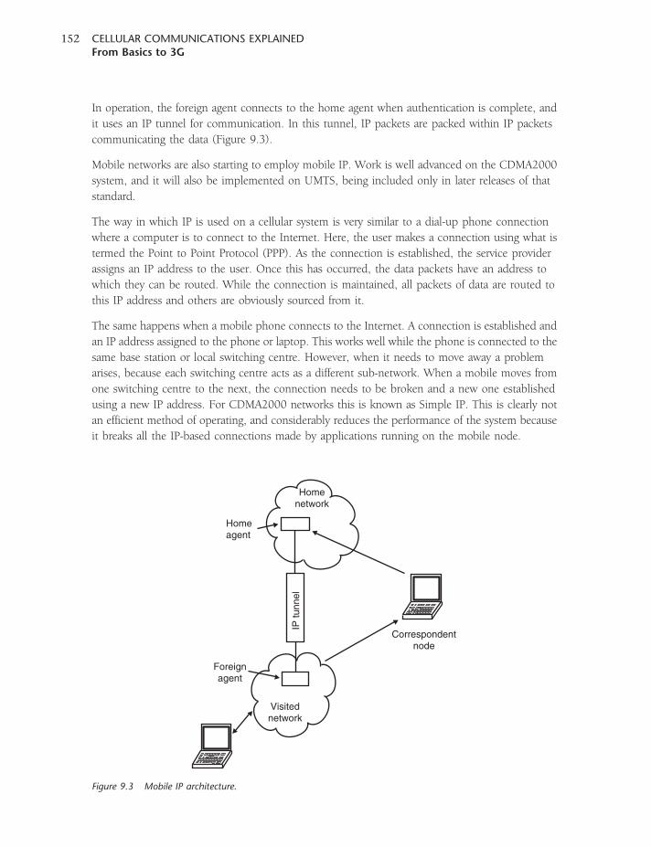
In operation, the foreign agent connects to the home agent when authentication is complete, and
it uses an IP tunnel for communication. In this tunnel, IP packets are packed within IP packets
communicating the data (Figure 9.3).
Mobile networks are also starting to employ mobile IP. Work is well advanced on the CDMA2000
system, and it will also be implemented on UMTS, being included only in later releases of that
standard.
The way in which IP is used on a cellular system is very similar to a dial-up phone connection
where a computer is to connect to the Internet. Here, the user makes a connection using what is
termed the Point to Point Protocol (PPP). As the connection is established, the service provider
assigns an IP address to the user. Once this has occurred, the data packets have an address to
which they can be routed. While the connection is maintained, all packets of data are routed to
this IP address and others are obviously sourced from it.
The same happens when a mobile phone connects to the Internet. A connection is established and
an IP address assigned to the phone or laptop. This works well while the phone is connected to the
same base station or local switching centre. However, when it needs to move away a problem
arises, because each switching centre acts as a different sub-network. When a mobile moves from
one switching centre to the next, the connection needs to be broken and a new one established
using a new IP address. For CDMA2000 networks this is known as Simple IP. This is clearly not
an efficient method of operating, and considerably reduces the performance of the system because
it breaks all the IP-based connections made by applications running on the mobile node.
IP tu
nnel
Visitednetwork
Correspondentnode
Foreignagent
Homeagent
Homenetwork
Figure 9.3 Mobile IP architecture.
CELLULAR COMMUNICATIONS EXPLAINEDFrom Basics to 3G
152
Accordingly, the mobile phone system is treated as a network in the same way as a wired network.
Each switching centre has a foreign agent, which operates in the same way that it does for a wired
LAN system. It communicates messages from a operating mobile that has moved away from its
home switching centre, and in this way the IP connection is not broken.
By adopting this approach the foreign agents serving different switching centres are used, and the
information is updated with the home agent as the mobile moves from one switching centre to the
next. Although this complicates the handover process it enables a continuous connection to be
maintained, despite the mobile moving its location and requiring to be served by different
switching centres.
With the telecommunications scene changing rapidly, moving from a voice-centred service to a
data-centred service and the hybrid approaches being offered to provide the optimum service,
Mobile IP is clearly going to become an increasingly important technique to be used to enable
seamless transition from one area to the next, and one technology to the next.
CHAPTER NINECDMA2000
153

10CHAPTER TEN
UMTS
UMTS, the Universal Mobile Telecommunications System, is the third-generation (3G) successor
to the second-generation GSM-based technologies, including GPRS, and EDGE. Although UMTS
uses a totally different air interface, the core network elements have been migrating towards the
UMTS requirements with the introduction of GPRS and EDGE. In this way, the transition from
GSM to UMTS does not require such a large instantaneous investment.
UMTS, which uses wideband CDMA (W-CDMA), has had a long history. Even as the first 2G
systems were first being rolled out, it was clear that these would not cater for the demand
forever. New technologies capable of providing new services and facilities would be required.
With this in mind, the World Administrative Radio Conference started to reserve spectrum
allocations for a new service at its meetings in 1992.
The next stage in the development arose when the International Telecommunications Union began
defining a system, and the International Mobile Telecommunications System 2000 (IMT2000)
started to take shape. In order to manage the new standard, a group known as the Third Generation
Partnership Programme (3GPP) was formed. In fact, 3GPP is a global co-operation between
six Organizational Partners (ARIB, CCSA, ETSI, ATIS, TTA and TTC) who are recognized as
being the world’s major standardization bodies from Japan, China, Europe, the USA and Korea.
The establishment of 3GPP was formalized in December 1998 by the signing of The Third
Generation Partnership Project Agreement.
The original scope of 3GPP was to produce globally applicable technical specifications and
technical reports for a third-generation mobile telecommunications system. This would be based
upon the GSM core networks and the radio access technologies that they support (i.e. Universal
Terrestrial Radio Access (UTRA), both Frequency Division Duplex (FDD) and Time Division
Duplex (TDD) modes). Later the scope of 3GPP was increased to include the maintenance and
development of the GSM Technical Specifications and Technical Reports, including its derivatives
of GPRS and EDGE.
In view of the fact that UMTS is a 3G technology and is a successor to GSM with a defined
migration path, some are now referring to it as 3GSM.
While 3GPP undertook the management of the UMTS standard, a similar committee was needed
to oversee the development of the other major 3G standard, namely CDMA2000. This committee
took on the name 3GPP2, and the standards bodies that were represented included ARIB, TTA,
CWTS and TIA.
Capabilities
UMTS uses W-CDMA as the radio transmission standard. It employs a 5-MHz channel bandwidth
(wider than the cdmaOne/CDMA2000 1XRTT channel bandwidth of 1.25MHz), and as such it
has the capacity to carry over 100 simultaneous voice calls, or to carry data at speeds up to 2Mbps
in its original format. However, with the later enhancements included in later releases of the
standard, new technologies (including HSDPA and HSUPA) have enabled data transmission
speeds of 14.4Mbps.
Many of the ideas that were incorporated into GSM have been carried over and enhanced for
UMTS. Elements such as the SIM have been transformed into a far more powerful USIM
(universal SIM). In addition to this, the network has been designed so that the enhancements
employed for GPRS and EDGE can be used for UMTS. In this way, the investment required is
kept to a minimum.
A new introduction for UMTS is that there are specifications that allow both FDD and TDD modes.
The first modes to be employed are FDD modes, where the uplink and downlink are on different
frequencies. The spacing between them is 190MHz for the Band 1 networks being currently used
and rolled out. However, the TDD mode where the uplink and downlink are split in time with the
base stations and then the mobiles transmitting alternately on the same frequency is particularly
suited to a variety of applications. An obvious example is where spectrum is limited and paired
bands suitably spaced are not available. It also performs well where small cells are to be used. As a
guard time is required between transmit and receive, this will be less when transit times are smaller
as a result of the shorter distances being covered. A further advantage arises from the fact that more
data are carried in the downlink as a result of Internet surfing, video downloads and the like. This
means that it is often better to allocate more capacity to the downlink. Where paired spectrum is
used this is not possible; however, when a TDD system is used it is possible to alter the balance
between downlink and uplink transmissions to accommodate this imbalance and thereby improve
the efficiency. In this way, TDD systems can be highly efficient when used in picocells for carrying
Internet data. The TDD systems have not been widely deployed, but this may occur more in the
future. In view of its character, it is often referred to as TD-CDMA (Time Division CDMA).
System architecture overview
Like GSM, the network for UMTS can be split into three main constituents. These are the mobile
station, called the User Equipment or UE, the base station sub-system, known as the Radio
Network Sub-system (RNS), and the core network.
User equipment
The user equipment is very much like the mobile equipment used within GSM. It consists
of a variety of different elements, including RF circuitry, processing, antenna, battery and the
CELLULAR COMMUNICATIONS EXPLAINEDFrom Basics to 3G
156
like. The UMTS/W-CDMA standard, with the many additional features and applications that can
run, requires far greater levels of processing than were needed for GSM, GPRS and EDGE.
Accordingly, the development programmes took longer than expected and the first phones
appeared somewhat later than had been hoped. The levels of integration required were much
greater than those needed previously, and this also resulted in higher drain on the battery. These
problems had to be overcome to ensure that users were not disappointed and found the battery
life of the new 3G phones much shorter than those of the old 2G and 2.5G phones. In addition to
this, many new integrated circuits combined both analogue RF and digital areas of the phone to
reduce the component count in the phones.
Another problem that had to be overcome resulted from the form of modulation used.
It required that a linear RF amplifier was used for the transmitter, unlike the GMSK modulation
used for GSM. The use of a linear RF amplifier increased the drain on the battery. To help
overcome this, a number of novel RF design techniques (which are not within the scope of
this book) were employed by designers to reduce the current drain, thereby improving the
battery life.
Use was also made of the improved battery technology that was coming available. Many older
phones had used nickel cadmium technology, but as batteries improved a move was made
to nickel metal hydride types. Lithium ion (Li-ion) batteries then became standard, and
they provided considerably greater energy storage densities, allowing phones to remain
small and relatively lightweight while still retaining or even improving the overall life between
charges.
The UE also contains a SIM card, although in the case of UMTS it is termed a USIM
(Universal Subscriber Identity Module). This is a more advanced version of the SIM card used
in GSM and other systems, but embodies the same types of information. It contains the
International Mobile Subscriber Identity number (IMSI) as well as the Mobile Station
International ISDN Number (MSISDN). The USIM may store more than one MSISDN, enabling the
phone to be used for a number of different ‘lines’ – home, business, etc. The USIM is also
programmed with an access priority control class. These classes are used to give different users
different levels of priority when accessing the system. Levels 0–9 are assigned to regular customers,
while 10–14 are assigned to users, such as the police and other safety personnel, who may need
to gain access even when the system might otherwise be nearing capacity. Other information
that the USIM holds includes the preferred language, to enable the correct language information
to be displayed, especially when roaming, and a list of preferred and prohibited Public Land
Mobile Networks (PLMN).
The USIM also contains a short message storage area that allows messages to stay with the user
even when the phone is changed. Similarly, ‘phone book’ numbers and call information regarding
the numbers of incoming and outgoing calls are stored.
The USIM is an integrated circuit assembly which contains the USIM Integrated Circuit Card
(UICC). The information stored is in the form of Elementary Files (EF). The UICC has eight
contacts available. The supply voltage is applied to pin 1, pin 2 is used as the reset line, and a clock
reference is supplied on pin 3. Pin 7 is used for the data input and output line. The UICC may
CHAPTER TENUMTS
157
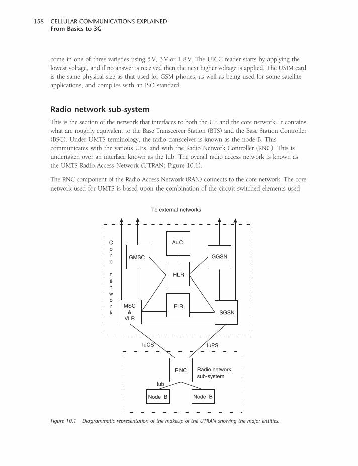
come in one of three varieties using 5 V, 3 V or 1.8 V. The UICC reader starts by applying the
lowest voltage, and if no answer is received then the next higher voltage is applied. The USIM card
is the same physical size as that used for GSM phones, as well as being used for some satellite
applications, and complies with an ISO standard.
Radio network sub-system
This is the section of the network that interfaces to both the UE and the core network. It contains
what are roughly equivalent to the Base Transceiver Station (BTS) and the Base Station Controller
(BSC). Under UMTS terminology, the radio transceiver is known as the node B. This
communicates with the various UEs, and with the Radio Network Controller (RNC). This is
undertaken over an interface known as the Iub. The overall radio access network is known as
the UMTS Radio Access Network (UTRAN; Figure 10.1).
The RNC component of the Radio Access Network (RAN) connects to the core network. The core
network used for UMTS is based upon the combination of the circuit switched elements used
GMSC
AuC
GGSN
SGSN
HLR
EIRMSC&
VLR
To external networks
Core
network
Node B Node B
RNC Radio networksub-system
IuPSIuCS
Iub
Figure 10.1 Diagrammatic representation of the makeup of the UTRAN showing the major entities.
CELLULAR COMMUNICATIONS EXPLAINEDFrom Basics to 3G
158
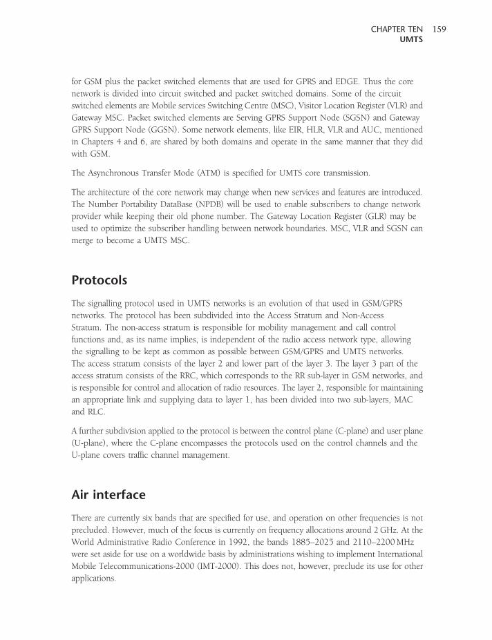
for GSM plus the packet switched elements that are used for GPRS and EDGE. Thus the core
network is divided into circuit switched and packet switched domains. Some of the circuit
switched elements are Mobile services Switching Centre (MSC), Visitor Location Register (VLR) and
Gateway MSC. Packet switched elements are Serving GPRS Support Node (SGSN) and Gateway
GPRS Support Node (GGSN). Some network elements, like EIR, HLR, VLR and AUC, mentioned
in Chapters 4 and 6, are shared by both domains and operate in the same manner that they did
with GSM.
The Asynchronous Transfer Mode (ATM) is specified for UMTS core transmission.
The architecture of the core network may change when new services and features are introduced.
The Number Portability DataBase (NPDB) will be used to enable subscribers to change network
provider while keeping their old phone number. The Gateway Location Register (GLR) may be
used to optimize the subscriber handling between network boundaries. MSC, VLR and SGSN can
merge to become a UMTS MSC.
Protocols
The signalling protocol used in UMTS networks is an evolution of that used in GSM/GPRS
networks. The protocol has been subdivided into the Access Stratum and Non-Access
Stratum. The non-access stratum is responsible for mobility management and call control
functions and, as its name implies, is independent of the radio access network type, allowing
the signalling to be kept as common as possible between GSM/GPRS and UMTS networks.
The access stratum consists of the layer 2 and lower part of the layer 3. The layer 3 part of the
access stratum consists of the RRC, which corresponds to the RR sub-layer in GSM networks, and
is responsible for control and allocation of radio resources. The layer 2, responsible for maintaining
an appropriate link and supplying data to layer 1, has been divided into two sub-layers, MAC
and RLC.
A further subdivision applied to the protocol is between the control plane (C-plane) and user plane
(U-plane), where the C-plane encompasses the protocols used on the control channels and the
U-plane covers traffic channel management.
Air interface
There are currently six bands that are specified for use, and operation on other frequencies is not
precluded. However, much of the focus is currently on frequency allocations around 2GHz. At the
World Administrative Radio Conference in 1992, the bands 1885–2025 and 2110–2200MHz
were set aside for use on a worldwide basis by administrations wishing to implement International
Mobile Telecommunications-2000 (IMT-2000). This does not, however, preclude its use for other
applications.
CHAPTER TENUMTS
159
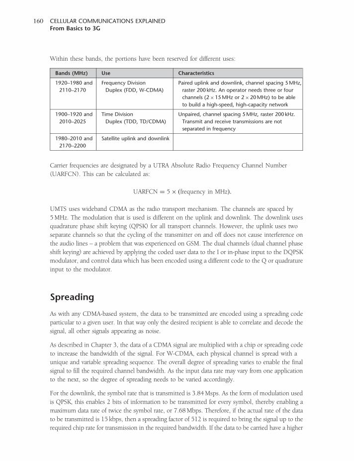
Within these bands, the portions have been reserved for different uses:
Bands (MHz) Use Characteristics
1920–1980 and
2110–2170
Frequency Division
Duplex (FDD, W-CDMA)
Paired uplink and downlink, channel spacing 5MHz,
raster 200 kHz. An operator needs three or four
channels (2�15MHz or 2�20MHz) to be able
to build a high-speed, high-capacity network
1900–1920 and
2010–2025
Time Division
Duplex (TDD, TD/CDMA)
Unpaired, channel spacing 5MHz, raster 200 kHz.
Transmit and receive transmissions are not
separated in frequency
1980–2010 and
2170–2200
Satellite uplink and downlink
Carrier frequencies are designated by a UTRA Absolute Radio Frequency Channel Number
(UARFCN). This can be calculated as:
UARFCN ¼ 5� ðfrequency in MHzÞ:
UMTS uses wideband CDMA as the radio transport mechanism. The channels are spaced by
5MHz. The modulation that is used is different on the uplink and downlink. The downlink uses
quadrature phase shift keying (QPSK) for all transport channels. However, the uplink uses two
separate channels so that the cycling of the transmitter on and off does not cause interference on
the audio lines – a problem that was experienced on GSM. The dual channels (dual channel phase
shift keying) are achieved by applying the coded user data to the I or in-phase input to the DQPSK
modulator, and control data which has been encoded using a different code to the Q or quadrature
input to the modulator.
Spreading
As with any CDMA-based system, the data to be transmitted are encoded using a spreading code
particular to a given user. In that way only the desired recipient is able to correlate and decode the
signal, all other signals appearing as noise.
As described in Chapter 3, the data of a CDMA signal are multiplied with a chip or spreading code
to increase the bandwidth of the signal. For W-CDMA, each physical channel is spread with a
unique and variable spreading sequence. The overall degree of spreading varies to enable the final
signal to fill the required channel bandwidth. As the input data rate may vary from one application
to the next, so the degree of spreading needs to be varied accordingly.
For the downlink, the symbol rate that is transmitted is 3.84Msps. As the form of modulation used
is QPSK, this enables 2 bits of information to be transmitted for every symbol, thereby enabling a
maximum data rate of twice the symbol rate, or 7.68Mbps. Therefore, if the actual rate of the data
to be transmitted is 15 kbps, then a spreading factor of 512 is required to bring the signal up to the
required chip rate for transmission in the required bandwidth. If the data to be carried have a higher
CELLULAR COMMUNICATIONS EXPLAINEDFrom Basics to 3G
160
data rate, then a lower spreading rate is required to balance this out. It is worth remembering that
altering the chip rate does alter the processing gain of the overall system, and this also needs to be
accommodated in the signal processing. Higher spreading factors are more easily correlated by the
receiver, and therefore a lower transmit power can be used for the same symbol error rate.
The codes required to spread the signal must be orthogonal if they are to enable multiple users and
channels to operate without mutual interference. The codes used in W-CDMA are Orthogonal
Variable Spreading Factor (OVSF) codes, and they must remain synchronous to operate. As it is not
possible to retain exact synchronization for this, a second set of scrambling codes is used to ensure
that interference does not result (Figure 10.2). This scrambling code is a pseudorandom number
(PN) code. Thus there are two stages of spreading: the first using the OSVF code, and the second
using a scrambling PN code. These codes are used to provide different levels of separation. The
OVSF spreading codes are used to identify the user services in the uplink and the user channels in
the downlink, whereas the PN code is used to identify the individual node B or UE.
On the uplink, there is a choice of millions of different PN codes. These are processed to include a
masked individual code to identify the UE. As a result, there are more than sufficient codes to
accommodate the number of different UEs likely to access a network. For the downlink, a short
code is used. There are a total of 512 different codes that can be used, one of which will be
assigned to each node B.
Synchronization
The level of synchronization required for the W-CDMA system to operate is provided by the
Primary Synchronization Channel (P-SCH) and the Secondary Synchronization Channel (S-SCH).
These channels are treated in a different manner to the normal channels, and as a result they are not
spread using the OVSFs and PN codes but rather by using synchronization codes. Two types are
employed: the first is called the primary code and is used on the P-SCH, while the second is named
a secondary code and is used on the S-SCH.
The primary code is the same for all cells, and is a 256-chip sequence that is transmitted during the
first 256 chips of each time slot. This allows the UE to synchronize with the base station for the
time slot.
Once the UE has gained time slot synchronization, it knows the start and stop of the time slot but
it does not have information about the particular time slot, or the frame. This is gained using the
secondary synchronization codes.
Spreading codeOVSF
Incomingdata
Scrambling code
Data stream tobe passed to
the RF sections
Figure 10.2 Spreading and scrambling process.
CHAPTER TENUMTS
161
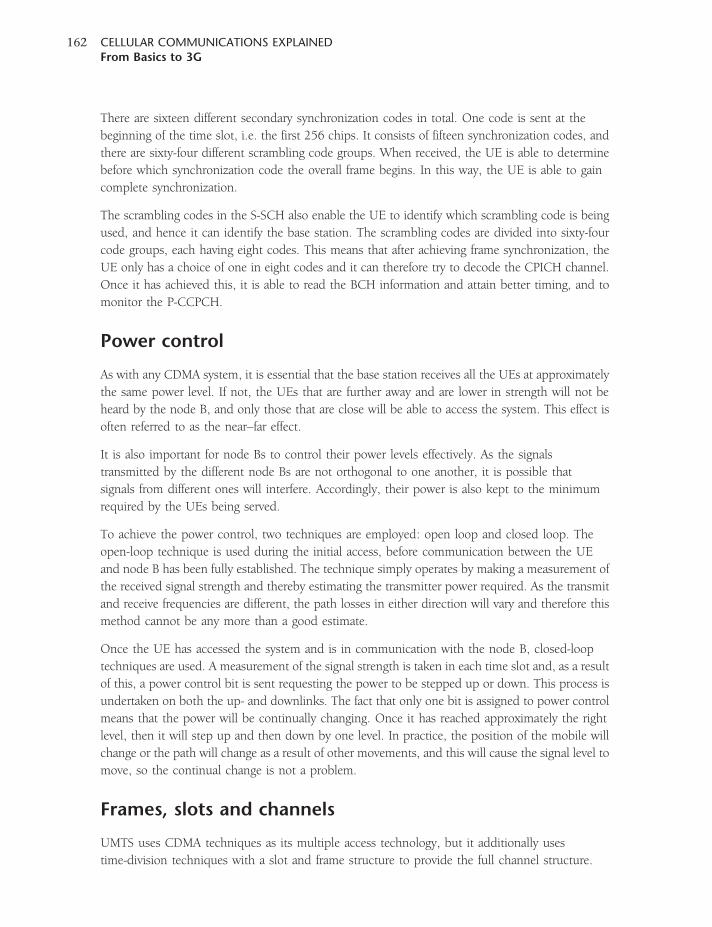
There are sixteen different secondary synchronization codes in total. One code is sent at the
beginning of the time slot, i.e. the first 256 chips. It consists of fifteen synchronization codes, and
there are sixty-four different scrambling code groups. When received, the UE is able to determine
before which synchronization code the overall frame begins. In this way, the UE is able to gain
complete synchronization.
The scrambling codes in the S-SCH also enable the UE to identify which scrambling code is being
used, and hence it can identify the base station. The scrambling codes are divided into sixty-four
code groups, each having eight codes. This means that after achieving frame synchronization, the
UE only has a choice of one in eight codes and it can therefore try to decode the CPICH channel.
Once it has achieved this, it is able to read the BCH information and attain better timing, and to
monitor the P-CCPCH.
Power control
As with any CDMA system, it is essential that the base station receives all the UEs at approximately
the same power level. If not, the UEs that are further away and are lower in strength will not be
heard by the node B, and only those that are close will be able to access the system. This effect is
often referred to as the near–far effect.
It is also important for node Bs to control their power levels effectively. As the signals
transmitted by the different node Bs are not orthogonal to one another, it is possible that
signals from different ones will interfere. Accordingly, their power is also kept to the minimum
required by the UEs being served.
To achieve the power control, two techniques are employed: open loop and closed loop. The
open-loop technique is used during the initial access, before communication between the UE
and node B has been fully established. The technique simply operates by making a measurement of
the received signal strength and thereby estimating the transmitter power required. As the transmit
and receive frequencies are different, the path losses in either direction will vary and therefore this
method cannot be any more than a good estimate.
Once the UE has accessed the system and is in communication with the node B, closed-loop
techniques are used. A measurement of the signal strength is taken in each time slot and, as a result
of this, a power control bit is sent requesting the power to be stepped up or down. This process is
undertaken on both the up- and downlinks. The fact that only one bit is assigned to power control
means that the power will be continually changing. Once it has reached approximately the right
level, then it will step up and then down by one level. In practice, the position of the mobile will
change or the path will change as a result of other movements, and this will cause the signal level to
move, so the continual change is not a problem.
Frames, slots and channels
UMTS uses CDMA techniques as its multiple access technology, but it additionally uses
time-division techniques with a slot and frame structure to provide the full channel structure.
CELLULAR COMMUNICATIONS EXPLAINEDFrom Basics to 3G
162
A channel is divided into 10-ms frames, each of which has fifteen time slots of 666microseconds.
On the downlink, the time is further subdivided so that the time slots contain fields that hold either
user data or control messages (Figure 10.3).
On the uplink, dual channel modulation is used so that both data and control are
transmitted simultaneously. Here, the control elements contain a pilot signal, Transport
Format Combination Identifier (TFCI), FeedBack Information (FBI) and Transmission
Power Control (TPC).
The channels carried are categorized into three groups: logical, transport and physical. The logical
channels define the way in which the data will be transferred; the transport channels, along with
the logical channel, also define the way in which the data are transferred; and the physical channels
carry the payload data and govern the physical characteristics of the signal.
The channels are organized such that the logical channels are related to what is transported,
whereas the physical layer transport channels deal with how, and with what characteristics. The
MAC layer provides data transfer services on logical channels. A set of logical channel types is
defined for different kinds of data transfer services.
Frame 10ms
Frame 10ms
666µs
Data and controltransmitted at thesame time
14
14
0
0
Control
Control
Data
Data
Downlink
Uplink
Figure 10.3 Frame and slot structure.
CHAPTER TENUMTS
163
Logical channels
1. Broadcast Control Channel (BCCH), DL. The broadcast control channel is a downlink (DL)
channel that broadcasts information relevant to that cell to the UEs in the service area.
Information includes the radio channels of neighbouring cells with their configurations, as well
as the available RACHs and scrambling codes.
2. Paging Control Channel (PCCH), DL. This downlink channel is associated with the PICH, and is
used for the transmission of paging messages as well as notification information.
3. Dedicated Control Channel (DCCH), UL/DL. This channel is used to carry dedicated control
information in both directions.
4. Common Control Channel (CCCH), UL/DL. This bi-directional channel is used to transfer
control information.
5. Shared Channel Control Channel (SHCCH), bi-directional. This channel is bi-directional but is
only found in the TDD form of UMTS, where it is used to transport shared channel control
information.
6. Dedicated Traffic Channel (DTCH), UL/DL. The DTCH is a bi-directional channel that is used to
carry the user data or traffic.
7. Common Traffic Channel (CTCH), DL. This unidirectional downlink channel is used to transfer
dedicated user information to a group of UEs.
Transport channels
1. Dedicated Transport Channel (DCH), UL/DL, mapped to DCCH and DTCH. This channel,
which is present in both uplink and downlink directions, is used to transfer data specific to a
particular UE. Each UE has its own DCH in each direction.
2. Broadcast Channel (BCH), DL, mapped to BCCH. This is a downlink channel that transmits or
broadcasts information to the UEs in the cell to enable them to identify the network and the
cell. Typically, it provides information about system information, system configuration
information and neighbouring radio channels. Of particular importance to UEs accessing the
network, it identifies the available random access channels and their scrambling codes. The UE
will also monitor the strength of the BCH to determine the relative signal strengths, and in this
way it can determine which cell it should access. It is also used in determining whether a
handover is required.
3. Forward Access Channel (FACH), DL, mapped to BCCH, CCCH, CTCH, DCCH and
DTCH. This channel appears in the downlink, and carries data or information to the
UEs that are registered on the system. There may be more than one FACH per cell, as
they may carry packet data. However, there is always one FACH that carries low-rate data to
enable mobiles to receive the FACH messages, and it operates without closed loop power
control.
4. Paging Channel (PCH), DL, mapped to PCCH. Like the paging channels on other systems such
as GSM, this channel carries messages that alert the UE to incoming calls, SMS messages, data
sessions, or required maintenance such as re-registration.
CELLULAR COMMUNICATIONS EXPLAINEDFrom Basics to 3G
164
5. Random Access Channel (RACH), UL, mapped to CCCH, DCCH and DTCH. Again, this channel
is similar in nature to the GSM random access channel, although this one carries requests for
service from UEs trying to access the system. By its nature the RACH is a shared channel that
any UE can access, and therefore mobiles requesting service will send a message. This is
acknowledged by the network, using the Acquisition Indicator Channel (AICH). If the RACH
request is not acknowledged, then the UE waits a random amount of time before sending
another access request.
6. Uplink Common Packet Channel (CPCH), UL, mapped to DCCH and DTCH. From its name it is
understood that this is an uplink only channel. It provides additional capability beyond that of
the RACH. If the mobile supports the use of this channel, it can access the system via this
channel and then continue to use it for transmitting small amounts of data. This channel uses
fast power control.
7. Downlink Shared Channel (DSCH), DL, mapped to DCCH and DTCH. This channel can be
shared by several users, and is used for data that are ‘bursty’ in nature – such as that obtained
from web browsing, etc. It is time-shared by the different users, and the UMTS packet
scheduling system dynamically assigns a particular slot on a carrier and code to a given UE that
has packets to transmit in the required direction. Once the data have been sent, the packet
scheduling system can assign the capacity to another UE.
Physical channels
1. Primary Common Control Physical Channel (PCCPCH), mapped to BCH. This channel
continuously transmits on the downlink, broadcasting the system identification and access
control information. Its spreading code is permanently allocated to 256 so that it provides an
overall transmission rate of 30 kbps. Half-rate convolutional coding is used, with interleaving
over two consecutive frames.
2. Secondary Common Control Physical Channel (SCCPCH), mapped to FACH, PCH. This is a
downlink channel that carries the Forward Access Channel (FACH), providing control
information, and the Paging Channel (PACH) with messages for UEs that are registered on the
network. The spreading factor is determined according to the capabilities of the UE, allowing
the fastest data transmission rate that the UE can handle.
3. Physical Random Access Channel (PRACH), mapped to RACH. This is an uplink channel that
enables the UE to transmit random access bursts in an attempt to access a network. In view of
the nature of the channel a fixed spreading factor is used, giving a data rate of 16 kbps.
4. Dedicated Physical Data Channel (DPDCH), mapped to DCH. This channel is used to transfer
user data on both the uplink and downlink. The spreading factor depends upon the data rates,
and also varies between the uplink and downlink because of the different modulation
schemes used. On the downlink the spreading factor can vary between 4 and 256, and on the
uplink it can vary from 4 to 512. Furthermore, the spreading factor can vary on a frame by frame
basis (see Figures 10.4 and 10.5).
5. Dedicated Physical Control Channel (DPCCH), mapped to DCH. This channel is present on both
the uplink and downlink. It carries control information to and from the UE. The channel carries
CHAPTER TENUMTS
165
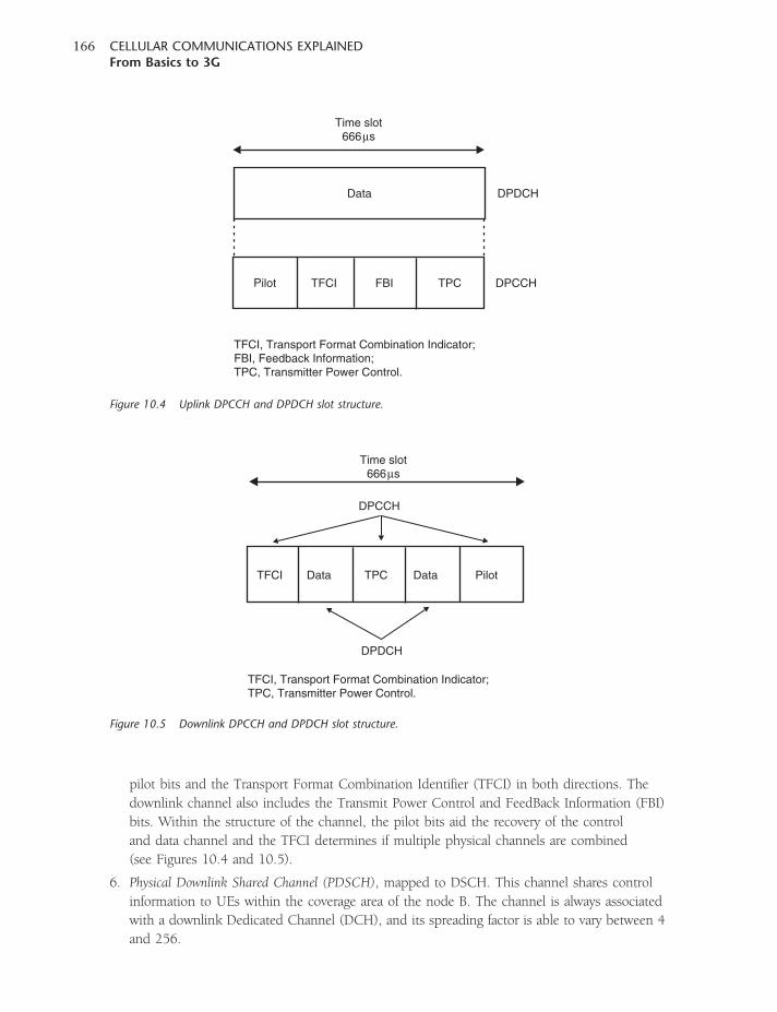
pilot bits and the Transport Format Combination Identifier (TFCI) in both directions. The
downlink channel also includes the Transmit Power Control and FeedBack Information (FBI)
bits. Within the structure of the channel, the pilot bits aid the recovery of the control
and data channel and the TFCI determines if multiple physical channels are combined
(see Figures 10.4 and 10.5).
6. Physical Downlink Shared Channel (PDSCH), mapped to DSCH. This channel shares control
information to UEs within the coverage area of the node B. The channel is always associated
with a downlink Dedicated Channel (DCH), and its spreading factor is able to vary between 4
and 256.
Data
Pilot TFCI FBI TPC
Time slot666µs
DPDCH
DPCCH
TFCI, Transport Format Combination Indicator;FBI, Feedback Information;TPC, Transmitter Power Control.
Figure 10.4 Uplink DPCCH and DPDCH slot structure.
Data PilotDataTFCI TPC
Time slot666µs
DPDCH
DPCCH
TFCI, Transport Format Combination Indicator;TPC, Transmitter Power Control.
Figure 10.5 Downlink DPCCH and DPDCH slot structure.
CELLULAR COMMUNICATIONS EXPLAINEDFrom Basics to 3G
166
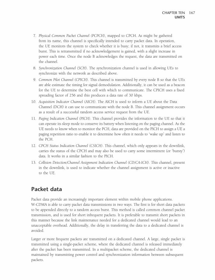
7. Physical Common Packet Channel (PCPCH), mapped to CPCH. As might be gathered
from its name, this channel is specifically intended to carry packet data. In operation,
the UE monitors the system to check whether it is busy; if not, it transmits a brief access
burst. This is retransmitted if no acknowledgement is gained, with a slight increase in
power each time. Once the node B acknowledges the request, the data are transmitted on
the channel.
8. Synchronization Channel (SCH). The synchronization channel is used in allowing UEs to
synchronize with the network as described above.
9. Common Pilot Channel (CPICH). This channel is transmitted by every node B so that the UEs
are able estimate the timing for signal demodulation. Additionally, it can be used as a beacon
for the UE to determine the best cell with which to communicate. The CPICH uses a fixed
spreading factor of 256 and this produces a data rate of 30 kbps.
10. Acquisition Indicator Channel (AICH). The AICH is used to inform a UE about the Data
Channel (DCH) it can use to communicate with the node B. This channel assignment occurs
as a result of a successful random access service request from the UE.
11. Paging Indication Channel (PICH). This channel provides the information to the UE so that it
can operate its sleep mode to conserve its battery when listening on the paging channel. As the
UE needs to know when to monitor the PCH, data are provided on the PICH to assign a UE a
paging repetition ratio to enable it to determine how often it needs to ‘wake up’ and listen to
the PCH.
12. CPCH Status Indication Channel (CSICH). This channel, which only appears in the downlink,
carries the status of the CPCH and may also be used to carry some intermittent (or ‘bursty’)
data. It works in a similar fashion to the PICH.
13. Collision Detection/Channel Assignment Indication Channel (CD/CA-ICH). This channel, present
in the downlink, is used to indicate whether the channel assignment is active or inactive
to the UE.
Packet data
Packet data provide an increasingly important element within mobile phone applications.
W-CDMA is able to carry packet data transmissions in two ways. The first is for short data packets
to be appended directly to a random access burst. This method is called common channel packet
transmission, and is used for short infrequent packets. It is preferable to transmit short packets in
this manner because the link maintenance needed for a dedicated channel would lead to an
unacceptable overhead. Additionally, the delay in transferring the data to a dedicated channel is
avoided.
Larger or more frequent packets are transmitted on a dedicated channel. A large, single packet is
transmitted using a single-packet scheme, where the dedicated channel is released immediately
after the packet has been transmitted. In a multipacket scheme, the dedicated channel is
maintained by transmitting power control and synchronization information between subsequent
packets.
CHAPTER TENUMTS
167
Speech coding
Speech coding in UMTS uses a variety of source rates. As a result, a range of vocoders is employed,
including the GSM EFR vocoder. When a variety of rates is available, a system known as Adaptive
Multi-Rate (AMR) may be employed where rate is chosen according to the system capacity and
requirements. This scheme is the same as that used on GSM and explained in Chapter 6. The
actual vocoder that is chosen is governed by the system.
The speech coding process can be combined with a voice activity detector. This is particularly
useful because during normal conversations there are long periods of inactivity. In the same way
that discontinuous transmission is applied to GSM, it is applied to UMTS. It employs the same
technique of inserting background noise when there is no speech, because when the discontinuous
transmission cuts out the transmission no background noise would otherwise be heard, which can
be very disconcerting for the listener.
Discontinuous reception
One of the big issues with mobile phones in general is that of battery life. It is one of the key
differentiators that people take into account when buying a phone, and this gives a measure of its
importance. Taking this into consideration when developing the UMTS/W-CDMA standard, a
discontinuous reception or sleep mode was introduced. This mode allows several non-essential
segments of the phone circuitry to power down during periods when paging messages will not
be received.
To enable this facility to be introduced into the UMTS UE circuitry, the paging channel is divided
into groups or sub-channels. The actual number of the paging sub-channel to be used by a
particular UE is assigned by the network, and in this way the UE has to listen for only part of the
time. To achieve this, the Paging Indicator Channel (PICH) is split into 10-ms frames, each of
which comprises 300 bits – 288 for paging data and 12 idle bits. At the beginning of each paging
channel frame there is a paging indicator (PI) that identifies the paging group being transmitted.
By synchronizing with the paging channels being transmitted, it is able to turn the receiver on
only when it needs to monitor the paging channel. As the receiver, with its RF circuitry, will
consume power, savings can be made by switching it off.
Access stratum protocol layers
The MAC sub-layer is responsible for mapping the logical channels and the transport
channels, ensuring optimum delivery of common and dedicated channel Protocol Data Units
(PDUs). To deal with the range of channels, the MAC is subdivided into a variety of areas.
These are the MAC-b, which is responsible for controlling the BCH; the MAC-c/sh, which
controls access to the common transport channels except for the HS-DSCH; the MAC-d, which
controls access to all dedicated transport channels; and the MAC-hs, which controls access to
the HS-DSCH.
CELLULAR COMMUNICATIONS EXPLAINEDFrom Basics to 3G
168
Sitting above the MAC layer is the Radio Link Control (RLC) layer, which is subdivided into three
entities. These entities provide the control parts supporting three modes of operation at layer 2.
The first is the Transparent Mode (TM), which transfers user data; and provides segmentation
and re-assembly of data units. The second is the Unacknowledged Mode (UM), which is similar
to the TM but also checks sequence numbers, and provides ciphering, padding and concatenation
where required. Thirdly, there is the Acknowledged Mode (AM), which supports flow control,
in-sequence delivery of upper-layer PDUs, error correction and duplicate detection.
The RLC also maintains the Quality of Service (QoS) as requested by the upper layers. This is
required to ensure that a quality of service appropriate to the requirements of the application is
received. There are four classes:
1. Conversational class (voice, video telephony, video gaming)
2. Streaming class (multimedia, video on demand, webcast)
3. Interactive class (web browsing, network gaming, database access)
4. Background class (email, SMS, downloading).
The top layer of the access stratum is called the Radio Resource Control (RRC) layer. This is a
complex layer which has many functions. These include the control of broadcast information, the
establishment and release of RRC connections and radio bearers, cell selection and re-selection,
paging, ciphering, integrity protection, and the control of UE measurement reporting.
Using these features, the RRC layer provides the signalling connections used by the upper,
non-access stratum layers, enabling information flow between the network and the UE.
There are two protocol states that can be adopted by the UE. The first is called Idle Mode, where
the UE performs cell searches. The second is known as Connected Mode. Here, the behaviour of
the UE is determined by the current state of the UE, of which there are four types: URA_PCH,
CELL_PCH, CELL_FACH and CELL_DCH.
In the first two states, the UE is searching for the most appropriate cell and decoding broadcast
system information. The UE can respond to paging in this mode. In the CELL_FACH mode, the
UE can act on RRC messages received on the BCCH, CCCH and DCCH. In the CELL_DCH mode,
the UE acts on messages received on the DCH.
Handover
Within UMTS, handover follows many concepts similar to those used for other CDMA systems
such as CDMA2000. There are three basic types of handover: hard, soft and softer. All three types
are used, but under different circumstances.
Hard handover is like that used for the previous generations of systems. Here, as the UE moves out
of range of one node B the call has to be handed over to another frequency channel. In this
instance, simultaneous reception of both channels is not possible.
CHAPTER TENUMTS
169
Soft handover is a technique that was not available on the previous generations of mobile phone
systems. With CDMA systems it is possible to have adjacent cell sites on the same frequency, and
as a result the UE can receive the signals from two adjacent cells at once, while these cells are also
able to receive the signals from the UE. When this occurs and handover is effected, it is known as
soft handover.
The decisions about handover are generally handled by the RNC. It continually monitors
information regarding the signals being received by both the UE and node B, and when a particular
link has fallen below a given level and another better radio channel is available, it initiates a
handover. As part of this monitoring process, the UE measures the Received Signal Code Power
(RSCP) and Received Signal Strength Indicator (RSSI) and the information is then returned to the
node B and hence to the RNC on the uplink control channel.
If a hard handover is required, then the RNC will instruct the UE to adopt a compressed mode,
allowing short time intervals in which the UE is able to measure the channel quality of other radio
channels.
Inter-system handover
While the primary handover strategy for a UMTS UE is to hand over to another UMTS node B, it
may be the case that no other suitable UMTS node B is available, particularly during the roll-out
phase of a 3G network. It is therefore expected that under these conditions the UE will perform an
intersystem handover. As GSM and UMTS have completely different air interfaces, this form of
handover is more complicated than a handover within UMTS or GSM. There are several reasons for
this. Obviously, the 5-MHz channel and use of CDMA against the 200-kHz channel width and
TDMA techniques are both hurdles to overcome. Another is the fact that UMTS continuously
transmits data, and this does not allow the single-receiver UE to tune to another RF channel while
communicating with the UMTS network.
To overcome this, a compressed mode has been provided within UMTS. This allows the UE to
adapt its transmission rate to provide for interruptions in the transmission when it can monitor the
GSM channels. These Transmission Gap Lengths (TGLs) are enabled by one of several methods –
by lowering the amount of data to be transmitted, reducing the spreading factor or puncturing the
error protection code. This feature is an essential element of UMTS, as it means that UEs can fall
back to GSM (or GPRS/EDGE) when the full UMTS service is not available. Although it may appear
to be particularly difficult, the fact that the updated GSM network has many common elements
with the UMTS network, and may even use the same elements, does mean that the handover is
simplified, at least a little.
The evolution of 3G networks
The maximum data transfer rate for UMTS is 2Mbps. With Wi-Fi and other technologies,
including wired ADSL links, providing much higher maximum download speeds and at lower cost,
there was a need to ensure that UMTS did not fall behind and as a result lose business. To address
CELLULAR COMMUNICATIONS EXPLAINEDFrom Basics to 3G
170
this, high-speed data packet access technology was introduced into UMTS. Additionally, trends
showed the volume of packet switched data rising and overtaking the more traditional circuit
switched traffic. Using the new HSDPA scheme, it is possible to achieve peak data rates of 10Mbps
within the 5-MHz channel bandwidth offered under W-CDMA.
The first stage of the upgrade was to increase the data rate on the downlink channel, where there
are typically more data transferred. This imbalance arises because of data downloads such as web
browsing, video clips and the like. The resulting technology was known as High Speed Downlink
Packet Access (HSDPA). In terms of the standards, Release 4 of the 3GPP W-CDMA standard
provided the efficient IP support to enable provision of services through an all IP core network.
Then Release 5 included HSDPA itself, with support for the packet-based multimedia services. In
Release 6, antenna array processing technologies were introduced to enhance the peak data rate to
about 30Mbps. This involves smart antennas using beam forming for handsets with one antenna,
and multiple-input multiple-output (MIMO) for UEs with up to four antennas.
As HSDPA needs to work alongside the original Release 99 systems, the new technology is
completely backwards compatible.
One of the keys to the operation of HSDPA was the use of an additional form of modulation.
Originally W-CDMA had used only QPSK as the modulation scheme; however, under the new
system 16-QAM (which can carry a higher data rate but is less resilient to noise) was specified for
when the link was sufficiently robust. The robustness of the channel and its suitability to use
16-QAM instead of QPSK is determined by analysing information fed back about a variety of
parameters. These include details of the channel physical layer conditions, power control and
quality of service, and information specific to HSDPA.
A scheme known as Hybrid Automatic Repeat Request (HARQ) was also implemented, along with
multi-code operation, and this eliminated the need for a variable spreading factor. By using these
approaches, all users, whether near or far from the base station, were able to receive the optimum
available data rate.
Improvements in the area of scheduling were also made. By moving more intelligence into the node
B, data traffic scheduling could be achieved in a more dynamic fashion. This enabled variations
arising from fast fading to be accommodated, with the cell even being able to allocate much of the
cell capacity for a short period of time to a particular user. In this way, the user was able to receive
the data as fast as conditions allow.
To be able to implement the improvements, a new channel termed the High Speed Downlink
Shared Channel (HS-DSCH) was introduced. W-CDMA normally carries data over dedicated
transport channels (DCHs), several of which are multiplexed onto one RF carrier. This approach
has been adopted because it provides the optimum performance with continuous user data. Under
the new scheme, the ‘bursty’ nature of the data has been accounted for and more efficient use
of the available spectrum has been made.
To enable all the HSDPA features to be implemented, a number of additional channels have been
introduced. The High-Speed Shared Control Channel (HS-SCCH) is the downlink signalling
CHAPTER TENUMTS
171
channel that carries key physical layer control information. This information enables the
demodulation of the data on HS-DSCH, and supports the data sent on HS-DSCH in the case of
retransmission or an erroneous packet. The information includes the channelization code set,
modulation scheme, transport block size, HARQ process information, redundancy and
constellation version, and new data indicator.
The High Speed Dedicated Physical Control Channel (HS-DPCCH) is the signalling channel that
carries the necessary control data in the up link. These consist of ARQ acknowledgements and the
quality feedback information from the downlink, which are required by the node B. It also carries
the downlink channel quality indicator (CQI) to indicate which estimated transport block size,
modulation type, etc. can be received correctly with a reasonable error rate in the downlink.
The High Speed Physical Downlink Shared Channel (HS-PDSCH) is the physical channel that
carries the user packet data in the downlink from the transport channel HS-DSCH. It has a fixed
spreading factor of sixteen and multicode transmission using up to fifteen codes. The peak data rate
is 10Mbit/s, and it is modulated using 16-QAM.
HSDPA adapts to varying downlink radio and overall channel conditions by modifying the effective
code rate, the modulation scheme, the number of codes used and the power per code. This enables
the scheme to cope with a wide dynamic range and thereby give all users, regardless of their
proximity or otherwise to the node B, the ability to make the best use of the high available
data rates.
Fast packet scheduling functions are performed in the node B. These functions manage the
HS-DSCH resources, and select the coding/modulation scheme and the power for the HS-DSCH
data packets. The handsets that should be scheduled are determined using CQI reports coming
from the UEs in question. Channel condition-dependent scheduling rather than sequential
scheduling can increase the capacity significantly and make better use of air interface resources.
Fast scheduling also allows guaranteed bit-rate services using packet scheduling, without the need
for a dedicated channel. Handsets are prioritized by the scheduler according to the channel
conditions, the amount of data pending in the buffer for each user, the elapsed time for that user
since last served, and pending retransmissions for a handset.
HSDPA was the first to be implemented because most of the data are transported in the downlink
direction. However, to support applications such as Voice over IP (VoIP) video-conferencing, and
some of the other new ideas that are being introduced, high-speed data transmission is required in
both directions. To this end, the equivalent for HSDPA, known as High Speed Uplink Packet
Access (HSUPA), is also being introduced and is part of Release 6 of the 3GPP specification. This
employs many of the same features found in HSDPA, but in the uplink direction. The upgrades
include adaptive modulation along with HARQ, as well as improvements in the base station similar
to those employed on HSDPA. While the maximum speed in the downlink direction is 14Mbps,
in the uplink it is less at 5.8Mbps.
CELLULAR COMMUNICATIONS EXPLAINEDFrom Basics to 3G
172
11CHAPTER ELEVEN
Position location
In recent years the importance of location services for mobile phone/cellular telecommunications
has risen significantly. One of the major reasons for this is the requirement to locate mobile phones
in the case of an emergency. For landlines it is a simple matter to trace the location of the call,
because by their very nature they are fixed. For mobile phones the matter is quite different, and
on many occasions the emergency services have had great difficulty in locating mobiles with any
degree of accuracy. With rulings such as the E911 directive in the USA requiring operators to
be able to locate mobile phones accurately, the concept of phone position location has become
more important.
A number of techniques are made available by cell phone operators, including cell identity
(Cell ID), Time Difference of Arrival (TDOA), Enhanced Observed Time Difference (EOTD),
Advanced Forward Link Trilateration (AFLT) and Assisted GPS (A-GPS). Of these, Cell ID, TDOA
and A-GPS are being widely used, with A-GPS emerging as the front runner. The other schemes have
not gained any real acceptance and commercial usage.
Cell ID
Cell identity is the most basic positioning system used in GSM, and for many years was the only
method of locating a mobile. It is a network-based method, and utilizes the fact that once the
mobile has registered with the network, the network has to know where the mobile is so that
it can be paged when there are incoming calls or text messages, etc. This information is available
from the network and the handset.
With the cell identified, the cell ID information is converted to a geographic position using
parameters from the network. This information is available in the coverage database at the Serving
Mobile Location Centre (SMLC).
The major drawback of this system is the level of accuracy. The location of the mobile can only be
determined to within a given cell. This will depend on the size of the cell, which in turn depends
on a number of factors. Cells for networks using the lower-frequency bands, such as 900MHz, tend
to be larger than those for networks operating at 1800MHz. The terrain will have a large effect, as
will the level of usage. In open country where usage levels are low, macrocells might be installed
that may have a radius of up to 35 km, whereas urban cells, where usage is much higher and signals
will not propagate as far, tend to be much smaller and may have a radius of 1 km or less. Some
picocells may only have a very small coverage area, and it would be possible to locate a mobile
accurately if one of these was used.
Moreover, many cells are sectored, and this will further narrow the area in which the mobile is
located. A sectored cell uses a number of antennas to split the cell; three are often used, providing a
coverage of 120�.
While Cell ID is limited in its accuracy, it has the advantage that it is possible to locate any cell
phone, however old, once it is registered onto the network.
TDOA
Time Difference of Arrival (TDoA) is another scheme that is in use, particularly in the USA. It
provides better location than cell ID, and operates by measuring the relative time of arrival of signals
transmitted by three base stations at the handset, or the signal transmitted by a mobile at three
base stations. As the radio signals travel at the speed of light, it is very easy to relate the time
of travel to a distance from the base station. As no absolute measurement is possible, the time
differences between signals are measured. The time difference between two signals enables a
hyperbolic line to be traced out on a map along which the mobile may be located. When
using the time differences between three stations, the hyperbolae intersect, providing a unique
location.
In order for this technique to work, there must be very accurate synchronization between the base
stations. Any differences will manifest themselves as offsets from the true position. However, unlike
some techniques, it does not require a large amount of data to be transmitted over the network for
it to operate. In view of the fact that data capacity is limited, any method of reducing it is welcomed
by network operators.
A-GPS
The most accurate technique, and that which seems to be gaining the widest level of acceptance, is
known as assisted GPS. It uses the Global Positioning System (GPS) as the basis of its operation,
but takes additional data to enable the GPS to operate under weak signal conditions, and to provide
the service required for mobile phone location.
Prior to looking at how A-GPS operates, a brief description of the operation of GPS is provided so
that the requirement for assistance can be understood.
GPS
The full operational system consists of a constellation of twenty-four operational satellites, with a
few more in orbit as spares in case one fails. The satellites are in one of six orbits, which are in
CELLULAR COMMUNICATIONS EXPLAINEDFrom Basics to 3G
174
planes that are inclined at approximately 55� to the equatorial plane. There are four satellites
in each orbit. This arrangement provides the user with a view of between five and eight satellites
at any time from any point on the Earth. When four satellites are visible, sufficient information is
available to be able to calculate the user’s position on Earth.
The GPS satellites need to be monitored and controlled from the ground, and it is necessary
to be in contact with each satellite for most of the time to be able to maintain the level
of performance required. To achieve this, there is a master station located at Falcon Air
Force Base, Colorado Springs, USA. However, other remote stations are located on Hawaii,
Ascension Island and Diego Garcia, and at Kwajalein. Using all these stations, the satellites
can be tracked and monitored for 92 per cent of the time. This results in two 1.5-hour
periods every day when each satellite is out of contact with the ground stations. This results
in two 1.5 hour periods every day when each satellite is out of contact with the ground
stations.
Figure 11.1 shows a GPS satellite being launched into orbit.
Using the network of ground stations, the performance of the GPS satellites is monitored
very closely. The information that is received at the remote stations is passed to the main
operational centre at Colorado Springs, and the received information is assessed. Parameters
such as the orbit and clock performance are monitored, and action taken to reposition the
satellite if it is drifting even very slightly out of its orbit, or to adjust the clock if necessary or,
more usually, to provide data to it indicating its error. This information is passed to three
uplink stations co-located with the downlink monitoring stations at Ascension Island,
Diego Garcia and Kwejalein.
The GPS operates by a process of triangulation. Each GPS satellite transmits information about the
time, and its position. By comparing the signals received from four satellites, the receiver is able to
deduce how long it has taken for the signals to arrive. From knowledge of the position of the
satellites, it can calculate its own position.
The GPS satellites transmit two signals on different frequencies. One is at 1575.42MHz and
the other is at 1227.6MHz. These provide two services, one known as course acquisition (C/A)
and the other as a precision (P) signal. The precision signal is only available for the military,
but the C/A elements of GPS are open to commercial use.
Both signals are transmitted using direct sequence spread spectrum (DSSS), and this enables all the
satellites to use the same frequency. They can be separated in the GPS receiver by the fact that they
use different orthogonal spreading codes, and this works in exactly the same way as the CDMA
cell phone systems. The spreading codes are accurately aligned to GPS time to enable decoding
of the signals to be facilitated.
The coarse acquisition signal at 1.5 GHz uses a 1.023-MHz spreading or chip code, while the
precision signal is transmitted at 1.2 GHz using a 10.23-MHz code. This precision signal is
encrypted, and uses a higher power level. Not only does this assist in providing a higher level of
accuracy; it also improves the reception in buildings.
CHAPTER ELEVENPosition location
175
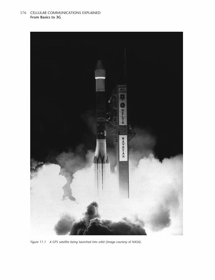
Figure 11.1 A GPS satellite being launched into orbit (image courtesy of NASA).
CELLULAR COMMUNICATIONS EXPLAINEDFrom Basics to 3G
176

All the GPS satellites continually transmit information, including what are termed Ephemeris data,
almanac data, satellite health information and clock correction data. Correction parameters for
the ionosphere and troposphere are also transmitted, as these have a small but significant effect on
signals even at these frequencies.
The Ephemeris data provide information that enables the precise orbit of the GPS satellite to be
calculated. The almanac data give the approximate position of all the satellites in the constellation,
and from this the GPS receiver is able to discover which satellites are in view. Although each
satellite contains an atomic clock, they all drift to a small extent and as a result details of the clock
offsets are transmitted. It is found that it is more effective to measure the error and transmit the data
than to maintain the clock exactly on time.
The data transmitted by the GPS satellite are formatted into twenty-five frames, each 1500 bits
in length. The frames are divided equally into five sub-frames. At a data transmission rate of
50 bits per second, it takes 6 seconds to transmit a sub-frame, 30 seconds to transmit a frame
and 12.5 minutes to transmit the complete set of twenty-five frames.
Sub-frames 1, 2 and 3 are the same for all data frames, and contain critical satellite-specific
information. This allows the receiver to determine a single satellite clock correction and Ephemeris
within 30 seconds. Sub-frames 4 and 5 contain less critical data that apply to the complete satellite
constellation, and these data are distributed throughout the twenty-five frames.
The strength of the GPS signal that is received on the surface of the earth is very low. Typically it is
around �127 dBm, although there is a variation on this arising from the elevation of the GPS
satellite. This may reduce the signal level by up to about 3 dB. To receive the signal a receiver
bandwidth of around 2MHz is often used, even though a chip rate of 1.023MHz is employed.
The reason for the wide bandwidth is that it reduces differential group delay, which would cause
positional errors.
With the wide bandwidth and low signal levels, the actual received signal is below the thermal
noise level. The only way to recover the signal is by correlation over a large number of chips.
Commonly, the correlation is done over a complete code cycle of 1023 chips, giving a correlation
time of 1ms. Using these techniques, the best receivers may receive signals down to levels of
around �142 dBm.
From a ‘cold start’, the GPS receiver chooses a satellite to look for and tries all possible code phases
to see if correlation is achieved. The problem is compounded by the Doppler shift on the satellite,
which forces the receiver to look in a number of Doppler ‘bins’ for each code phase, thus increasing
the search time. If no satellite is found, then the search is repeated for the next satellite.
Modern receivers speed up this search by using large numbers of correlators in parallel.
Tens of thousands of correlators are typically used.
Once the first signal has been correlated, the GPS receiver can demodulate the data the signal
carries. With the almanac data available, the GPS receiver is able to deduce which satellites are
visible and hence which ones to receive. Additionally, this enables the receiver to correlate the
signals more quickly.
CHAPTER ELEVENPosition location
177
The receiver measures the relative phases of the signals from each of the satellites to provide
what are termed ‘pseudoranges’. The GPS receiver then uses the Ephemeris data and also
compensates for elements such as the clock offsets, effects of the ionosphere and troposphere,
and even relativity. The receiver uses all of this information to calculate its own clock error and
position. The overall calculation is somewhat involved, and uses iterative processes to reach the
final result.
In view of the time taken to correlate with the GPS satellites, as well as the time taken to transmit
the data, the Time To First Fix (TTFF) is usually in excess of 12.5minutes. Faster TTFF times from
a cold start are often achieved by using a vast number of correlators, and this approach means that
it is not always necessary to wait until all the data have been received before the first fixes can
be made.
Assistance from the base station
The problem with GPS for mobile phone applications is that signal levels are low, and the receiver
needs to have a direct view of the satellite. This can cause problems when the phone is used in a
building, or even in an urban area where a direct view of the satellite is masked. Additionally, the
time taken for the receiver to lock – the Time To First Fix (TTFF) – can be as much as 10 minutes
or more from switch-on. This is not acceptable when emergency calls are being made, as a much
faster acquisition time is required. To achieve this, assistance is required for the GPS receiver,
thereby giving rise to the requirement for Assisted GPS.
A-GPS
The system known as Assisted GPS or A-GPS uses the mobile phone network to assist the GPS
receiver in the mobile phone to overcome the problems associated with TTFF, and the low signal
levels that are encountered in some situations.
For A-GPS, the network provides the Ephemeris data to the cell phone GPS receiver, and this
improves the TTFF. This can be achieved by incorporating a GPS receiver into the base station
itself, and as this is sufficiently close in position to the mobile, the data received by the base station
are sufficiently accurate to be transmitted on to the mobiles. The base station receiver is obviously
on all the time, and will be located in a position where it can ‘see’ the satellites.
The information provided can be either the Ephemeris data for visible satellites or, more
helpfully, the code phase and Doppler ranges over which the mobile has to search – i.e.
‘acquisition data’. These ranges can be estimated as the position of the mobile is bounded,
because it must be within the cell served by the particular base station. This technique is able
to improve the TTFF by many orders of magnitude.
Assisted GPS is also used to improve the performance within buildings where the GPS signals are
attenuated by 20 dB or possibly more. Again, by providing information to the GPS receiver in the
mobile it is able better to correlate the signal being received from the satellite when the signal is low
in strength. Using this technique it is possible to gain considerable increases in sensitivity,
CELLULAR COMMUNICATIONS EXPLAINEDFrom Basics to 3G
178
and some manufacturers have claimed it is possible to receive signals down to power levels of
around �159 dBm. The base station supplies the receiver with navigation message bits –
‘sensitivity data’.
Several techniques are used to pass the assistance data from the base station to the mobile. For
GSM, GPRS, EDGE and CDMA2000, the information is transmitted as packet data requiring a
new session to be activated. For UMTS, a data channel is used and the information is broadcast
to the users. In this way, the level of data is reduced.
CHAPTER ELEVENPosition location
179

12CHAPTER TWELVE
Conformance and interoperabilitytesting
Testing of mobile phone designs before they enter service and are used on a live network is
particularly important. Users expect their phones to operate correctly – to be able to make calls,
and for all the features to work as intended – under all conditions. The huge variety of phones
on the market means that a user can easily change to another manufacturer, and in a market
that is very sensitive a manufacturer can soon get a poor name. With the vast number of
phones of any given design being produced, recalling them is not normally a viable option.
Additionally, it has been known for incorrectly operating phones to cause problems to the
network operator.
Ensuring that phones operate virtually perfectly is not an easy task. The specifications used to
define the standard are usually very extensive, and can be open to interpretation in some places.
Essential operations such as registration require many transactions between the phone and the
network, and as a call proceeds the network and phone have to keep in communication with one
another to ensure that the call is maintained. Handover and other scenarios then introduce further
complications. All these interactions must proceed correctly, despite the huge number of
communications that are undertaken under a wide variety of scenarios. With the introduction
of 3G these protocol exchanges have become increasingly complicated, and still demand the
same high level of operation. In addition to this, many physical elements of the phone need to
be tested – from ensuring that the phone can be heard, to checking that people using them
do not absorb too much RF energy.
Types of test
To ensure that a phone meets its required standards, it has to undergo a variety of types of test.
It should naturally pass basic safety tests to ensure that there is no way that it can cause
harm or injury.
Similarly, it also needs to undergo what is called Specific Absorption Rate (SAR) testing. This
involves the use of an anatomically correct model of the human head. Sensors are set up inside the
model to measure the temperature rises to ensure that the heating effect is within acceptable limits.
It is necessary to check the protocol operation of the phone and, with the complicated protocols
used in mobile phones, this is a critical area. If the phone protocol software operates incorrectly,
then it could result in problems experienced not only by the phone but also on the network. In view
of the complexity of the protocols, this testing can be very involved. Specialized network simulators
are used, and these testers emulate a variety of network entities – i.e. base stations or node Bs, RNC
(Radio Network Controller) and the like. In this way a host of scenarios from registration to
handover, and in fact any situation that can be encountered, can be simulated.
RF testing is also undertaken. Many measurements of the transmitter and receiver performance are
undertaken in a variety of areas, such as the out-of-band emissions. Measurements of the
Radio Resource Management (RRM) are undertaken to ensure that the control capability of the
phone is operating correctly. There are, for instance, very tight limits on the control of the
transmitter output power to ensure that the phone radiates only as much as is needed under
any given condition, and that the noise in the phone bands is reduced to the minimum level.
To achieve this, a protocol tester is often used to control the phone and set up the relevant
scenarios. In addition to this, RF measurement and generation equipment is required. This is often
in the form of additional signal generators, power meters, analysers, noise generators, etc. To check
operation of the phone with multi-path and fading, special fading simulators are required.
It is also necessary to test the operation of the SIM or, in the case of 3G UMTS phones, the USIM.
As SIMs are interchangeable between phones, the interface must be rigorously checked.
It is also vital to verify the security aspects of the operation of the SIM, as lapses in security could
compromise elements of the network security. To undertake this testing, a SIM simulator
(or USIM simulator) is required. This simulator emulates the operation of the SIM, and tests on the
phone can then be run using a protocol tester to set up the variety of scenarios that are needed.
Finally, audio checks are undertaken. These check the correct operation of the audio aspects of the
phone, in terms of both the microphone and the earphone. Checks of audio levels, quality and
much more are measured, using a variety of equipment, to ensure they conform to the
requirements laid down.
Test cases
It is obviously necessary to ensure that each stage in the testing is repeatable, regardless of the
test equipment used and the organization performing the testing.
To achieve uniformity, a large number of what are termed ‘test cases’ are defined. These were
originally defined by ETSI (European Telecommunications Standards Institute) for GSM, but they
are now controlled by 3GPP (Third Generation Partnership Project).
For GSM these test cases were written in prose, and they described the test itself, the
set-up conditions and the applied stimuli, and of course the pass and fail criteria. It was then
possible for each test equipment manufacturer to implement these tests on their equipment.
However, to ensure that the tests are a faithful implementation of the original intent,
a validation and certification process has been set up.
CELLULAR COMMUNICATIONS EXPLAINEDFrom Basics to 3G
182
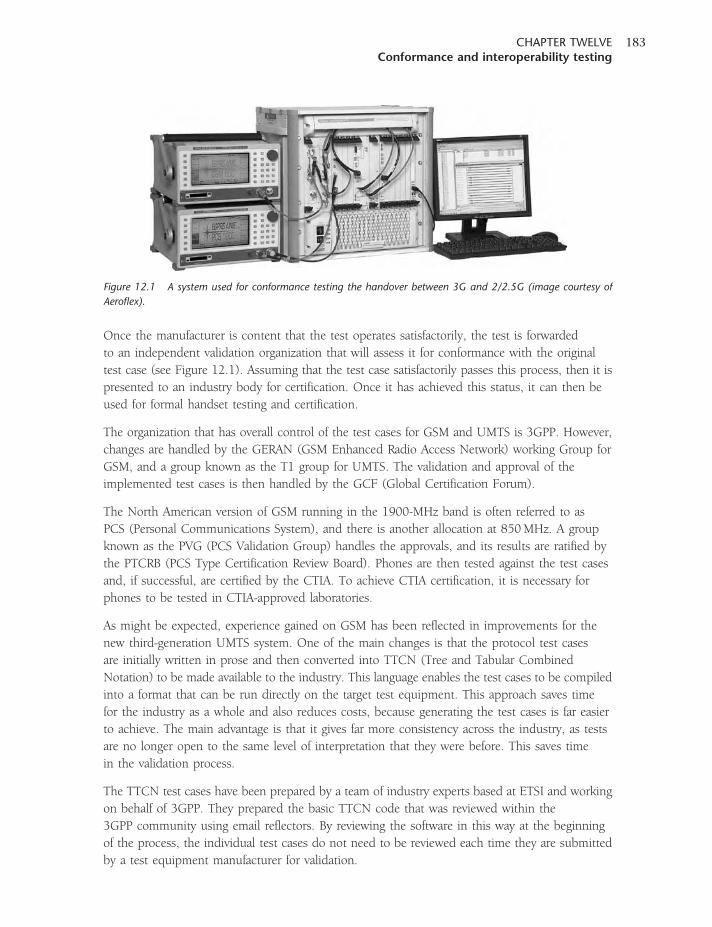
Once the manufacturer is content that the test operates satisfactorily, the test is forwarded
to an independent validation organization that will assess it for conformance with the original
test case (see Figure 12.1). Assuming that the test case satisfactorily passes this process, then it is
presented to an industry body for certification. Once it has achieved this status, it can then be
used for formal handset testing and certification.
The organization that has overall control of the test cases for GSM and UMTS is 3GPP. However,
changes are handled by the GERAN (GSM Enhanced Radio Access Network) working Group for
GSM, and a group known as the T1 group for UMTS. The validation and approval of the
implemented test cases is then handled by the GCF (Global Certification Forum).
The North American version of GSM running in the 1900-MHz band is often referred to as
PCS (Personal Communications System), and there is another allocation at 850MHz. A group
known as the PVG (PCS Validation Group) handles the approvals, and its results are ratified by
the PTCRB (PCS Type Certification Review Board). Phones are then tested against the test cases
and, if successful, are certified by the CTIA. To achieve CTIA certification, it is necessary for
phones to be tested in CTIA-approved laboratories.
As might be expected, experience gained on GSM has been reflected in improvements for the
new third-generation UMTS system. One of the main changes is that the protocol test cases
are initially written in prose and then converted into TTCN (Tree and Tabular Combined
Notation) to be made available to the industry. This language enables the test cases to be compiled
into a format that can be run directly on the target test equipment. This approach saves time
for the industry as a whole and also reduces costs, because generating the test cases is far easier
to achieve. The main advantage is that it gives far more consistency across the industry, as tests
are no longer open to the same level of interpretation that they were before. This saves time
in the validation process.
The TTCN test cases have been prepared by a team of industry experts based at ETSI and working
on behalf of 3GPP. They prepared the basic TTCN code that was reviewed within the
3GPP community using email reflectors. By reviewing the software in this way at the beginning
of the process, the individual test cases do not need to be reviewed each time they are submitted
by a test equipment manufacturer for validation.
Figure 12.1 A system used for conformance testing the handover between 3G and 2/2.5G (image courtesy of
Aeroflex).
CHAPTER TWELVEConformance and interoperability testing
183
To test a new handset, the manufacturer generally approaches a qualified test house which
will possess a variety of different test systems. The test house will then run the required
certified test cases and be able to present a case for a handset being suitable for use on the
available networks.
CDMA system
A different approach to that used by GSM/UMTS has been adopted by the CDMA-based systems.
The emphasis of testing is on interoperability with the network, rather than conformance with
a specification. This has the advantage that it checks that the phone actually works on the network.
For CDMA2000, the standards are written by 3GPP2. This is the equivalent of 3GPP, but for the
CDMA standard IS-2000. These standards are then published by the relevant standards body for a
particular area. In North America, this is the TIA (Telecommunications Industry Association); for
Japan it is the ARIB (Association of Radio Industries and Businesses), etc. In North America, testing
is carried out under the auspices of either the CDG (CDMA Development Group) or the CTIA.
Testing is then conducted in three stages. Stage 1 testing verifies the RF performance of a system,
checking parameters such as receiver sensitivity, and performance under fading conditions.
In addition to this, protocol testing is undertaken. Stage 2 is what is termed ‘cabled interoperability
testing’. Here, the focus is on the interoperability of a handset with a particular base station.
If a network has base stations from one manufacturer, then the handset will be tested against this.
In this way, any operational anomalies between the two will be discovered. Tests ensure that the
mobile performs in the correct manner with the base station under a variety of conditions,
including call set-up, handoff and call termination. Finally, Stage 3 testing is undertaken by an
operator and consists of running the mobile on a live network to ensure that it works over the air.
This may include what is termed a ‘drive test’, where the mobile is driven around a live network
and its performance checked under real conditions.
The testing carried out under CTIA auspices is undertaken by approved laboratories. These use
test equipment to simulate the network, and tests similar to those in CDG Stages 1 and 2 are
employed. Once mobile phones have successfully passed the CTIA tests, they are given
an approval certificate.
Different test requirements are placed upon handset manufacturers by the various network
operators, and therefore phones may undergo a variety of tests under either CDG or CTIA auspices,
or both.
Although the idea of interoperability testing is well established, there is a move towards the
conformance testing approach. Part of the reason behind this is to ensure a higher degree of
commonality between phones. This will facilitate aspects such as roaming, where there is a greater
need for phones to work on a variety of networks. This aspect has been seen as one of the major
successes of GSM, as a GSM phone will work on any network around the globe. Currently
CDMA phones tend to be targeted towards a particular network, and there may be minor
differences between networks.
CELLULAR COMMUNICATIONS EXPLAINEDFrom Basics to 3G
184
Summary
With well over a billion and a half subscribers connected to GSM networks alone, and many
millions of phones being produced each year, testing is a major element in the production of a
mobile phone design. It is particularly important to operators that phones work correctly. If they do
not operate correctly, it is likely that users will change their network as well as the phone, not
knowing where the problem lies. With the enormous levels of competition between the variety of
network operators and also between the different phone manufacturers, none can afford poor levels
of performance. Adequate testing in the development stages can save considerable amounts of
money later – far outweighing the cost of any test equipment purchased.
CHAPTER TWELVEConformance and interoperability testing
185


Glossary
1X RTT The abbreviation used to describe the first phase of CDMA2000 that
uses a single 1.25-MHz bandwidth RF carrier channel. The abbreviation
RTT stands for Radio Transmission Technology spreading, and the
1X element indicates that it uses the spreading required for one 1.25-MHz
channel.
3GPP Third Generation Partnership Programme. The standards body and organization
used to develop and coordinate W-CDMA/UMTS development.
3GPP2 Third Generation Partnership Programme 2. The standards body and
organization used to coordinate the development of CDMA2000 in the USA.
3X RTT The version of CDMA2000 that will be capable of higher data rates than 1X
systems. It uses a spreading rate of three times the basic 1X technology.
RTT stands for Radio Transmission Technology.
ACELP Algebraic Code Excited Linear Prediction. A vocoder technique used in GSM
and NA-TDMA.
ADPCM Adaptive Differential Pulse Code Modulation. A form of speech coding widely
used for wireless local loop networks and cordless phones employing a 32-kbps
data rate.
Air interface The interface between the mobile phone and the base station. Often this refers
to the protocols used in this area.
AM Amplitude Modulation. A form of modulation used widely on the long-,
medium- and short-wave broadcast bands. It involves changing the amplitude of
the signal in line with the instantaneous amplitude of the incoming audio or
modulating signal.
AMPS Advanced Mobile Phone System. The analogue first-generation mobile phone
system used extensively in North America and many other countries.
ANSI American National Standards Institute. The main North American standards
approving body.
ARQ Automatic Repeat reQuest. A form of error correction system whereby when
errors are detected by the receiver, it sends a repeat request so that the data with
errors are re-sent.
AuC Authentication Centre. The database used to control the authentication process
and compare the users’ identification with those recognized as valid by the
network.
Authentication A process used to validate a user before allowing the user onto the network.
Authentication
key
The secret 64-bit word used in the North American authentication process.
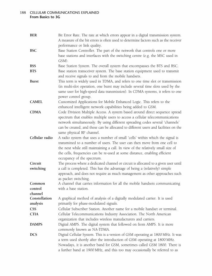
BER Bit Error Rate. The rate at which errors appear in a digital transmission system.
A measure of the bit errors is often used to determine factors such as the receiver
performance or link quality.
BSC Base Station Controller. The part of the network that controls one or more
base stations and interfaces with the switching centre (e.g. the MSC used in
GSM).
BSS Base Station System. The overall system that encompasses the BTS and BSC.
BTS Base station transceiver system. The base station equipment used to transmit
and receive signals to and from the mobile handsets.
Burst This term is widely used in TDMA, and refers to one time slot or transmission
(in multi-slot operation, one burst may include several time slots used by the
same user for high-speed data transmission). In CDMA systems, it refers to one
power control group.
CAMEL Customized Applications for Mobile Enhanced Logic. This refers to the
enhanced intelligent network capabilities being added to GSM.
CDMA Code Division Multiple Access. A system based around direct sequence spread
spectrum that enables multiple users to access a cellular telecommunications
network simultaneously. By using different spreading codes several ‘channels’
can be created, and these can be allocated to different users and facilities on the
same physical RF channel.
Cellular radio A radio system that uses a number of small ‘cells’ within which the signal is
transmitted to a number of users. The user can then move from one cell to
the next while still maintaining a call. In view of the relatively small size of
the cells, frequencies can be re-used at some distance, enabling efficient
occupancy of the spectrum.
Circuit
switching
The process where a dedicated channel or circuit is allocated to a given user until
a call is completed. This has the advantage of being a (relatively) simple
approach, and does not require as much management as other approaches such
as packet switching.Common
control
channel
A channel that carries information for all the mobile handsets communicating
with a base station.
Constellation
analysis
A graphical method of analysis of a digitally modulated carrier. It is used
primarily for phase-modulated signals.
CSS Cellular Subscriber Station. Another name for a mobile handset or terminal.
CTIA Cellular Telecommunications Industry Association. The North American
organization that includes wireless manufacturers and carriers.
DAMPS Digital AMPS. The digital system that followed on from AMPS. It is more
commonly known as NA-TDMA.
DCS Digital Cellular System. This is a version of GSM operating at 1800MHz. It was
a term used shortly after the introduction of GSM operating at 1800MHz.
Nowadays, it is another band for GSM, sometimes called GSM 1800. There is
a further band at 1900MHz, and this too may occasionally be referred to as
CELLULAR COMMUNICATIONS EXPLAINEDFrom Basics to 3G
188

DCS 1900 although the original term was PCS 1900 (Personal Communications
System).
DECT Digital Enhanced Cordless Telephone. A European cordless telephone standard.
Diversity A receiving technique employing two antennas spaced apart from each other
so that reception conditions will be different for both. The receiver then switches
between antennas to ensure the best reception is maintained at all times.
Downlink This is also known as the forward link, and is the transmission path from the
base station to the mobile.
DSSS Direct Sequence Spread Spectrum. A form of transmission used for a number
of applications, including CDMA phone technology, where data are multiplied
by a spreading code to spread the signal over a wide bandwidth. Only when it
is correlated with the same spreading code in the receiver can the data be
extracted.
DTx Discontinuous Transmission. This is a method of reducing the transmission time
of a mobile handset by cutting the transmission when no audio is present.
Dual band Phones that operate on two bands, but with one standard or radio access
technology. Many phones may be triple or even quad band now.
Dual mode This refers to phones that are able to operate on two standards or radio access
technologies.
Dual Tone
Multiple
Frequency
A method of transmitting numbers over a phone line by using two tones,
different combinations of which represent different numbers.
Eb/N0 This term is the energy per bit divided by the noise power spectral density. The
energy per bit is simply the signal power, and hence this term is effectively a
form of signal-to-noise ratio.
EDGE Enhanced Data for Global Evolution. Sometimes referred to as Enhanced Data
for GSM Evolution, this is a system that uses packet switched data along with
8PSK modulation and other updates to provide enhanced data rate transfer over
what is basically a GSM network.
EIR Equipment Identity Register. A database used within GSM that retains
information about whether a mobile phone has been stolen.
Enhanced
Variable Rate
Vocoder
An 8-kHz vocoder that can be used on CDMA networks to provide improved
voice quality of the QCELP vocoder normally used.
Erlang A measure of radio channel usage – 1 Erlang is equivalent to one telephone
line being used permanently.
ERP Effective Radiated Power. The level of power radiated by an antenna in the
required direction.
FDD Frequency Division Duplex. The technique where transmission and reception
(i.e. forward and reverse channels) use different frequencies.
FDMA Frequency Division Multiple Access. The multiple access scheme that allows
different users access to a cellular telecommunications network by assigning
them different frequencies.
GLOSSARYGlossary
189
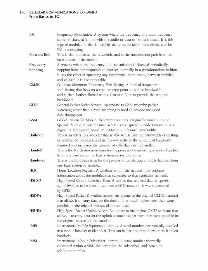
FM Frequency Modulation. A system where the frequency of a radio frequency
carrier is changed in line with the audio or data to be transmitted. It is this
type of modulation that is used by many walkie-talkie transceivers, and for
FM broadcasting.
Forward link This is also known as the downlink, and is the transmission path from the
base station to the mobile.
Frequency
hopping
A process where the frequency of a transmission is changed periodically,
hopping from one frequency to another, normally in a pseudorandom fashion.
It has the effect of spreading any interference more evenly between mobiles,
and as such it is less noticeable.
GMSK Gaussian Minimum Frequency Shift Keying. A form of frequency
shift keying that keys on a zero crossing point to reduce bandwidth,
and is then further filtered with a Gaussian filter to provide the required
bandwidth.
GPRS General Packet Radio Service. An update to GSM whereby packet
switching rather than circuit switching is used to provide increased
data throughput.
GSM Global System for Mobile telecommunications. Originally named Groupe
Speciale Mobile, it was renamed when its use spread outside Europe. It is a
digital TDMA system based on 200-kHz RF channel bandwidths.
Half-rate This term refers to a vocoder that is able to use half the bandwidth of existing
or established vocoders, and in this way reduces the amount of bandwidth
required and increases the number of calls that can be handled.
Handoff This is the North American term for the process of transferring a mobile handset
from one base station or base station sector to another.
Handover This is the European term for the process of transferring a mobile handset from
one base station to another.
HLR Home Location Register. A database within the network that contains
information about the mobiles that subscribe to that particular network.
HSCSD High Speed Circuit Switched Data. A service that allowed data at speeds
up to 64 kbps to be transmitted over a GSM network. It was superseded
by GPRS.
HSDPA High Speed Packet Downlink Access. An update to the original UMTS standard
that allows it to carry data on the downlink at much higher rates than were
possible in the original releases of the standard.
HSUPA High Speed Packet Uplink Access. An update to the original UMTS standard that
allows it to carry data on the uplink at much higher rates than were possible in
the original releases of the standard.
IMEI International Mobile Equipment Identity. A serial number electronically installed
in a mobile handset to identify it. This can be used to immobilize or track stolen
handsets.
IMSI International Mobile Subscriber Identity. A serial number (normally
contained within a SIM) that identifies the subscriber, and hence the
telephone number.
CELLULAR COMMUNICATIONS EXPLAINEDFrom Basics to 3G
190
InterRAT
handover
A handover that takes place between two different radio access technologies.
This occurs when the coverage of one system does not extend as far as that
of another. This occurrence is widespread whilst 3G is being deployed and
handsets need to hand over from a 3G service to a 2G service as the handset
moves outside the coverage area of the 3G network. It is less of an issue with
CDMA2000 services, as there is backward compatibility between the different
levels of service.
Intersymbol
interference
A form of interference caused by reflections in the signal path giving rise to
some portions of the signal travelling over different path lengths. This results
in time delays, which can mean that different symbols arrive at the same time,
resulting in interference between them.
Intersystem
handover
(handoff )
A handover that takes place when a mobile hands over from one radio access
technology to another.
Intracell
handover
(handoff )
A handover from one frequency to another within the same cell.
LPC-RPE Linear Prediction Coding with Regular Pulse Excitation. A vocoder technique
used in GSM.
Macrocell A cell covering a large area, often several kilometres in diameter.
MAHO Mobile Assisted Handover (Handoff). This occurs when the mobile handset
assists in the handover process by making measurements, for example of signal
strength, to assist the base station in the handover process.
Microcell A cell covering a very small area, often less than 500 metres in diameter.
Typically one is created by having a low-power base station and placing the
antenna below the height of the surrounding buildings. In this way the radiation
will follow the pattern of the street.
Modulation The process of changing the radio frequency carrier signal in line with the audio
signal or data to be transmitted. This modulation is then extracted by the
receiver, and the original audio or data can be recreated.
MSC Mobile Switching Station. The switching centre where the mobile network
interfaces to the public telephone system.
MTSO Mobile Telephone Switching Office. The switching centre used in the AMPS
system that controls base stations and also interfaces to the public telephone
system.
NAMPS Narrowband AMPS. A narrowband version of the AMPS standard developed
by Motorola using a 10-kHz channel bandwidth rather than the 30 kHz used
by AMPS. It was aimed at overcoming the problem of spectrum crowding.
As cellular technology became more widespread, voice quality was poorer,
and it was overtaken by 2G technology. In view of these reasons, it was not
widely deployed.
NA-TDMA North American TDMA. The digital second-generation system first adopted
in the USA. It uses time division multiple access (TDMA) technology, and
this has given rise to its name. Also known as Digital AMPS and US Digital
GLOSSARYGlossary
191
Cellular, it is specified under standard IS-136, having been initially issued
as IS-54.
NMT Nordic Mobile Telephone. The analogue (1G) standard that was developed
in Scandinavia and was the first mobile phone system to be commercially
deployed (1979).
Node B A terminology used within UMTS to denote a base station.
Open loop This refers to the fact that CDMA systems in particular require considerable
degrees of power control. Such control is normally undertaken with
feedback loop in operation between the base station and the mobile
handset. However, there are some instances (for example when a handset
has just been switched on and is registering) when this information is not
available. The handset will then operate ‘open loop’, making an estimate
of the power required, dependent upon the signal it is receiving from the
base station.
Origination The process of starting or originating a call. This is done by the handset
when the user dials a call.
Orthogonal
codes
The codes used as spreading codes when generating DSSS (CDMA) signals.
They are said to be orthogonal if, when they are summed over a period of time,
they add to zero.
Packet
switching
The process whereby data are segmented into packets, each of which is
typically a few milliseconds long. These packets are then transmitted along
whatever channel is available. As there are normally dead periods when no
data are transmitted by a particular user, this system makes more efficient
use of the available capacity than does the circuit switched approach.
Paging channel The channel used by the mobile handset in GSM and CDMA to monitor
whether there is an incoming call about to arrive.
PCS Personal Communications System. This normally refers to GSM used on the
1900-MHz band. It is now just called GSM or, occasionally, GSM 1900.
PDC Pacific Digital Cellular, sometimes also referred to as Personal Digital
Cellular. The 2G TDMA system similar to NA-TDMA that is widely used
in Japan.
PLMN Public Land Mobile Network. The landline or wired side of the mobile network,
i.e. the infrastructure.
PM Phase Modulation. A form of modulation where the phase of the signal is
modulated in line with the audio or data to be transmitted. This form of
modulation is used in many data applications.
PN Pseudorandom number. A number that is generated mathematically to create
an almost random number sequence. By using the same start or ‘seed’ number,
the number can be recreated and therefore it is not fully random.
PSTN Public Switched Telephone Network. The public landline-based telephone
network.
QCELP Qualcomm Code Excited Linear Prediction. The vocoder used in cdmaOne/
CDMA2000.
CELLULAR COMMUNICATIONS EXPLAINEDFrom Basics to 3G
192
Rake receiver A receiver used for reception of CDMA signals that enables multi-path signals
to be coherently combined to reinforce one another.
RAT Radio Access Technology. This refers to the type of cellular system that is in
use. GSM, NA-TDMA, W-CDMA and CDMA 2000 are all different radio
access technologies.
Registration The process whereby a mobile gives information to the network so that it can
gain access.
Reverse link A term used to describe the link from the mobile to the base station.
RF Radio Frequency. Pertaining to those parts of a system that manipulate the
signals at high or radio frequencies.
Rho This is a transmitter performance measurement that gives an indication of
transmitter quality.
Roaming The process that enables a mobile to be used on a different network to the
one for which it was originally intended. It occurs when travelling outside
the coverage area of the original network, e.g. when abroad.
SID System Identifier. A code sent by base stations to indicate a particular operator
or geographic area.
SIM Subscriber Identity Module. The card used initially just in GSM phones, but
now more widely used to carry the personal subscriber information. Swapping
the SIM card from one phone to another enables users to swap phones
while retaining their number and other personal information.
SINAD This is similar to the signal-to-noise ratio, but includes other forms of unwanted
signal. It is actually the ratio of signalþ noiseþ distortion to noiseþ distortion.
Like the signal-to-noise ratio it is widely used as an indication of signal quality,
and under specified conditions it can be used as a measure of receiver
performance.
SMS Short Message Service. A service initially used on GSM that enables messages
up to 160 characters to be sent by one mobile and received by another.
SNR Signal-to-noise ratio. This is the ratio of the signal to the background noise,
and is used as an indication of signal quality. Under specified conditions it
can be used as a measure of receiver performance. It is sometimes denoted
as S/N.
Soft handover
(handoff )
This is the ability, used in CDMA, of a mobile to be able to handover
when it can hear two base stations at once. In this way it can make the
connection to the new base station before relinquishing the connection with
the previous one.
Softer handover
(handoff )
A term applicable to cdmaOne/CDMA2000, this is a soft handover between
two sectors of the same base station.
TACS Total Access Communications System. The analogue first-generation system
widely used within Europe and a number of other countries.
TDD Time Division Duplex. The concept of using timesharing to enable
forward and reverse channels to be accommodated on the same channel
or frequency.
GLOSSARYGlossary
193
TDMA Time Division Multiple Access. The concept whereby multiple users share the
same channel by being assigned different timeslots. This scheme is used in a
number of digital cell phone systems, including GSM, NA-TDMA and PDC.
TIA Telecommunications Industry Association. An industry association based in
North America that organizes standards bodies for the telecommunications
industry.
TMSI Temporary Mobile Subscriber Identity. A temporary identifier assigned to
a subscriber by a network.
UE User Equipment. The term used in W-CDMA for a mobile handset.
UMTS Universal Mobile Telecommunications System. The name given to the
third-generation system that has been developed as a migration path for GSM.
It is also known as Wideband CDMA (W-CDMA).
Uplink Another term for the reverse link, i.e. the link from the mobile to the base
station.
VLR Visitor Location Register. The database that is used to hold information on
mobiles that are ‘visitors’ to the network, i.e. roaming.
Vocoder A voice encoder. A codec used for encoding and decoding voice signals.
Vocoders utilize many of the characteristics of speech to encode signals far
more efficiently than if they were other forms of signal.
Walsh codes A family of orthogonal codes used in CDMA technology.
W-CDMA Wideband CDMA. The third-generation mobile phone system that has
been developed as the migration path from GSM. It is also known as UMTS.
CELLULAR COMMUNICATIONS EXPLAINEDFrom Basics to 3G
194
Index
1XRTT, 136
3GPP, 155
3XRTT, 136
8PSK, 100
A
AC, 125
Access Channel, 125
Access Grant Channel, 85
Access stratum protocol layer, 168
ACELP, 108
Acknowledgement Channel, 151
Acquisition Indicator Channel, 167
Adaptive modulation, 144
Adaptive Multi-Rate, 89, 168
Advanced Mobile Phone System, 6, 67
AGCH, 85
A-GPS, 174
AICH, 167
Algebraic Code Excited Linear Prediction, 108
AM, 27
Amplitude modulation, 27
AMPS channels, 69
AMPS signalling, 72
AMPS voice messaging, 71
AMPS, 6, 10, 67
AMR, 89, 168
ANSI J-STD-008, 113
Assisted GPS, 174
Attenuation (by atmosphere), 24
AuC, 80, 110
Authentication, 110
Authentication Centre, 80, 110
B
Bandwidth, FM, 35
Base station controller, 61, 80
Base station, 69, 104
Base Transceiver Station, 61, 80
BCCH, 85, 109, 164
BCH, 164
Beam formatting, 139
Bessel function, 34
Binary Phase Shift Keying, 38
BPSK, 38
Broadcast Channel, 109, 164
Broadcast Control Channel, 85, 164
Broadcast services, 145
BSC, 61, 80
BTS, 61, 80
C
C450, 10
Call processing, 131
Call set-up, 56
Carrier Sense Multiple Access, 75
Carrier, 27
CCCH, 164
CD/CA-ICH, 167
CDMA advantages, 133
CDMA, 8, 12, 44, 55
CDMA2000 1X, 8, 11, 134, 135
CDMA2000 1xEV-DO, 8, 11, 134, 148
CDMA2000, 8, 134
cdmaOne, 8, 11, 113
Cell (concept), 52
Cell ID, 171
CELP, 65, 133
Channel usage, 59
Chip code, 45
Chunks, 101
Closed-loop power control, 129
Cluster (cells), 52
Code Division Multiple Access, 12, 55
Coded Excited Linear Prediction, 65, 133
Coded Orthogonal Frequency Division
Multiplex, 47
COFDM, 47
Collision Detection/Channel Assignment
Indication Channel, 167
Common Control Channel, 164
Common Pilot Channel, 167
Common Traffic Channel, 164
Compander, 72
Conformance test, 181
Constellation diagram, 39
Control Channel, 150
Correspondent node, 151
CPCH Status Indication Channel, 167
CPCH, 165
CPICH, 167
CSICH, 167
CSMA, 75
CTCH, 164
D
DAMPS, 103
Data Rate Control Channel, 151
DCCH, 105, 108, 164
DCH, 162
DCS1800, 7, 10
Dedicated Control Channel, 164
Dedicated Physical Control Channel, 165
Dedicated Physical Data Channel, 165
Dedicated Traffic Channel, 164
Dedicated Transport Channel, 164
Demodulation, 28
Demodulator, FM, 33
Deviation ratio, 33
Diffraction, 22
Digital AMPS, 103
Digital Control Channel Locator, 107
Digital Control Channel, 105, 108
Digital Traffic Channel, 106
Digital Verification Colour Code,
105, 107
Direct Sequence Spread Spectrum, 44
Discontinuous reception, 130, 168
DL, 107
Downlink Shared Channel, 165
Downlink slow power control, 129
DPCCH, 165
DPDCH, 165
DSCH, 165
DSSS, 44
DTCH, 106, 164
Duplex operation, 55
DVCC, 105, 107
E
EDGE data coding, 101
EDGE timeslots, 100
EDGE, 8, 11, 100
EFR, 89
EIR, 80
Electric field, 13
Electromagnetic spectrum, 18
Electromagnetic wave, 15
Electronics Serial Number, 122
Enhanced Data rates for Global Evolution, 8
Enhanced Data rates for GSM Evolution, 8
Enhanced Full Rate Vocoder, 89
Enhanced Variable Rate Codec, 131
Equipment Identity Register, 80
Erlang, 60
ESN, 122
EVRC, 131
Extended TACS, 68
F
FACCH, 86, 107
FACH, 164
F-ACKCH, 147
Fading, 22
F-APICH, 140
Fast Associated Control Channel, 86, 107
Fast call set-up, 148
Fast fading, 24
F-ATDPICH, 140
F-BCCH, 140
FBI, 163
F-CCCH, 140
FCCH, 85
F-CPCCH, 140
F-DCCH, 141
FDD, 55
FDMA, 12, 54
Feedback Information, 163
F-FCH, 141
F-GCH, 147
F-ICCH, 147
Field effect transistor, 5
FM, 32
FOCC, 74, 105
Foreign agent, 151
Forward Access Channel, 164
Forward Acknowledgement Channel, 147
Forward Auxiliary Transmit Diversity
Channel, 140
Forward Broadcast Control Channel, 140
Forward Common Control Channel, 140
Forward Common Power Control Channel, 140
Forward Control Channel, 74
Forward Dedicated Auxiliary Pilot Channel, 140
Forward Dedicated Control Channel, 141
Forward Fundamental Channel, 141
INDEX196
Forward Grant Channel, 147
Forward Indicator Control Channel, 147
Forward Packet Data Channel, 144
Forward Packet Data Control Channel, 144
Forward Paging Channel, 140
Forward Pilot Channel, 139
Forward Quick Paging Channel, 140
Forward Supplemental Channel, 141
Forward Supplemental Code Channel, 141
Forward Sync Channel, 140
Forward Traffic Channel, 119
Forward Transmit Diversity Pilot
Channel, 140
F-PCH, 140
F-PDCCH, 144
F-PDCH, 144
F-PICH, 139
F-QPCH, 140
Frequency Correction Channel, 85
Frequency Division Duplex, 55
Frequency Division Multiple Access, 12, 54
Frequency hopping, 43, 92
Frequency Modulation, 32
Frequency Shift Keying, 37
Frequency to wavelength conversion, 17
Frequency, 17
F-SCCH, 141
F-SCH, 141
FSK, 37
F-SYNCH, 140
FTC, 120
F-TDPICH, 140
G
Gateway GPRS Support Node, 94, 159
Gateway MSC, 159
Gaussian filtered Phase Shift Keying, 40
Gaussian Minimum Shift Keying, 82
GCF, 181
General Packet Radio Service, 8, 93
GGSN, 94, 159
Global Certification Forum, 183
Global Positioning System, 174
Global System for Mobile Communications,
7, 79
GMSK, 40, 82
GPRS coding, 95
GPRS mobile classes, 95
GPRS operation, 98
GPRS physical channel, 96
GPRS, 8, 10, 93
GPS, 172
Groupe Speciale Mobile, 7
GSM call initiation, 90
GSM ending a call, 91
GSM initialisation, 90
GSM receiving a call, 91
GSM, 7, 10, 79
H
Handoff, 58, 109, 130, 142
Handover, 58, 91, 169
Hard handoff, 130
HARQ, 146
High Speed Circuit Switched Data, 93
High Speed Dedicated Physical Control
Channel, 172
High Speed Downlink Shared Channel, 171
High Speed Packet Downlink Access, 156
High Speed Packet Uplink Access, 156
High Speed Shared Control Channel, 171
HLR, 57, 80
Home agent, 151
Home Location Register, 57, 80
HSCSD, 93
HSDPA, 156, 171
HS-DSCH, 171
HS-PDSCH, 172
HS-SCCH, 171
HSUPA, 156
Hybrid Automatic Repeat Request, 146
I
IMEI, 81
IMSI, 81, 157
IMT-2000, 155
Infrastructure, 60
International Mobile Equipment Identity, 81
International Mobile Subscriber
Identity, 81, 157
Intersymbol interference, 24
Inter-system handover, 170
I-Q modulator, 40
IS-136, 103
IS-2000, 135
IS-54, 103
IS-856, 148
IS-95, 113
INDEX 197
L
Layers, 94
LOCAID, 105
Logical channels, 164
LPC-RPE, 88
M
Macrocell, 53
Magnetic field, 14
Man–machine interface, 64
MCS, 101
Medium Access Control Channel, 150
MEID, 148
Microcell, 53
MIN, 71
Minimum Phase Shift Keying, 40
MMI, 64
Mobile Equipment Identifier, 148
Mobile Identifier Number, 71
Mobile IP, 151
Mobile phone, 62
Mobile Services Switching Centre, 159
Mobile Station International ISDN Number, 157
Mobile Switching Centre, 61, 62, 70, 80, 104
Mobile Telephone Switching Office, 70
Modulation (IS-95), 124
Modulation and coding schemes, 101
Modulation index, 31, 33
Modulation, amplitude, 27
frequency, 32phase, 37
Morse telegraph, 2
MS idle state, 131
MS initialization, 131
MS traffic state, 131
MSC, 104
MSC, 61, 62, 70, 80, 159
MSISDN, 157
MSK, 40
MTSO, 70
Multicast services, 147
Multiple access schemes, 53
N
NAMPS, 10
NA-TDMA, 8, 103
Network coverage, 25
Network planning, 25
NMT, 6, 10, 67
Nordic Mobile Telephone, 6, 67
North American TDMA, 8, 103
Nyquist’s theorem, 49, 65
O
OCQPSK, 138
Octets, 101
OFDM, 47
Offset Phase Shift Keying, 40
Open loop power control, 129
O-QPSK, 40
Orthogonal code, 44
Orthogonal Complex Quadrature Phase
Shift Keying, 138
Orthogonal Frequency Division Multiplex, 47
Orthogonal Variable Spreading Factor code, 161
Orthogonal Variable Spreading Function, 138
OVSF, 138, 159
P
PACCH, 98
Pacific Digital Cellular, 8, 111
Packet Access Grant Channel, 98
Packet Associated Control Channel, 98
Packet Broadcast Control Channel, 97
Packet Data Traffic Channel, 98
Packet data, 142, 167
Packet Notification Channel, 98
Packet Paging Channel, 98
Packet Random Access Channel, 98
Packet Timing Advance Common Control
Channel, 98
PAGCH, 98
Paging Channel, 57, 85, 117, 164
Paging Control Channel, 164
Paging Indication Channel, 167
Paging message, 58
Paging, 109
PBCCH, 97
PCCH, 164
PCCPCH, 165
PCG, 127
PCH, 85, 164
PCPCH, 167
PCS Type Certification Review Board, 183
PCS Validation Group, 183
PCS1900, 7, 10
PDC, 8, 10, 111
PDSCH, 166
Personal Digital Cellular, 8
Phase modulation, 37
INDEX198
Phase Shift Keying, 38
Physical Common Packet Channel, 167
Physical Downlink Shared Channel, 166
Physical Random Access Channel, 165
PICH, 167
Picocell, 53
Pilot Channel, 115, 150
PM, 37
PN code, 114
PNCH, 98
Polarization, 19
Position location, 173
Potential gradient, 14
Power Control Group, 128
Power control, 128, 139, 162
PPCH, 98
PRACH, 98, 165
Primary Common Control Physical
Channel, 165
Primary Synchronization Channel, 161
Propagation (radio waves), 20
P-SCH, 161
PSK, 38
PTCCH, 98
PTCRB, 183
PTDCH, 98
PVG, 183
Q
QAM, 42
QCELP, 133
QPSK, 39
Quadrature Amplitude Modulation, 42
Quadrature detector, 33
Quadrature Phase Shift Keying, 39
Qualcomm Coded Excited Linear Prediction, 133
R
RACH, 85, 141, 165
R-ACKCH, 144
Radio carrier, 27
Radio configurations, 135
Radio Network Sub-system, 156, 158
Radio spectrum, 18
Radio telephone, 6
Radio wave, 15
Radio, 2
Random Access Channel, 58, 85, 165
Rate Set 1, 120
Rate Set 2, 120
R-CCCH, 141
R-CQICH, 144
R-DCCH, 142
R-EACH, 141
RECC, 105
RECC, 75
Reflected signals, 22
Reflection, 22
Refraction, 20
Release D (CDMA2000 1xEV-DV), 146
Removable User Identity Module, 65
Reverse Access Channel, 141
Reverse Acknowledgement Channel, 144
Reverse Channel Quality Indicator Channel, 144
Reverse Common Control Channel, 141
Reverse Control Channel, 75
Reverse Dedicated Control Channel, 142
Reverse Enhanced Access Channel, 142
Reverse Fundamental Channel, 142
Reverse Packet Data Channel, 144
Reverse Packet Data Control Channel, 146
Reverse Pilot Channel, 141
Reverse Rate Indicator Channel, 151
Reverse Request Channel, 146
Reverse Secondary Pilot Channel, 147
Reverse Supplemental Channel, 142
Reverse Supplemental Code Channel, 142
Reverse Traffic Channel, 127
R-FCH, 142
RNS, 154, 158
R-PDCCH, 146
R-PDCH, 146
R-PICH, 141
R-REQCH, 142
RS1, 122
RS2, 122
R-SCCH, 142
R-SCH, 142
R-SPICH, 147
RTC, 126
RUIM, 65
S
SACCH, 86, 107
SAR, 181
SAT, 73
SC, 120
SCCPCH, 165
SCF, 109
SCH, 85, 167
INDEX 199
SCI, 117
SDCCH, 86
Secondary Common Control Physical Channel, 165
Secondary Synchronization Channel, 161
Selective cell, 53
Semiconductor invention, 4
Serving GPRS Support Node, 94, 159
SGSN, 94, 159
Shannon’s Law, 50
Shared Channel Feedback, 109
Shared Control Channel, 164
Shared Secret Data, 110
SHCCH, 164
Short Message Paging and Access Response
Channel, 109
Short Message Service, 7, 93
SID, 70
Sidebands, 34
Signal to noise ratio improvement, 36
Signalling Tone, 74
SIM test, 182
SIM, 65
Slow Associated Control Channel, 86, 107
Slow fading, 23
SMS, 7, 93
SOC, 106
Soft handoff, 130
Softer handoff, 130
SPACH, 109
Specific Absorption Rate, 181
Spectrum re-use, 51
Speech coding, 168
SPF, 108
Spreading codes, 44, 114
Spreading Rate 1, 136
Spreading Rate 2, 136
S-SCH, 161
SSD, 110
ST, 74
Standalone Dedicated Control
Channel, 86
Subscriber Identity Module, 65
Superframe Phase, 108
Supervisory Audio Tone, 73
Synchronization Channel, 85, 119, 167
Synchronization, 161
Synchronized Capsule Indicator, 117
Synchronous demodulation, 29
System Identifier, 70
System Operator Code, 106
T
TACS, 6, 10, 67
TCH, 86
TDD, 55
TDMA, 12, 54
TDOA, 172
TD-SCDMA, 9, 11
Telegraph, 1
Telephone, 2
Temporary Mobile Subscriber Identity, 82
Test cases, 182
TFCI, 163, 166
Thermionic valve, 4
Time Difference of Arrival, 174
Time Division Duplex, 55
Time Division Multiple Access, 12, 54
Time to First Fix, 178
TMSI, 82
Total Access Communications System, 6, 67
TPC, 163
Traffic channel, 86, 145
Transistor invention, 4
Transmission Power Control, 163
Transport channels, 164
Transport Format Combination Identifier,
163, 166
TTFF, 178
U
UARFCN, 160
UE, 156
UICC, 157
Umbrella cell, 53
UMTS Radio Access Network, 158
UMTS, 8, 11, 155
Universal Mobile Telecommunications System,
8, 155
Universal Subscriber Identity Module, 65, 157
Universal Terrestrial Radio Access, 157
Uplink Common Packet Channel, 165
US Digital Cellular, 103
USDC, 103
User Equipment, 156
USIM Integrated Circuit Card, 157
USIM, 65, 157
US-TDMA, 10
UTRA Absolute Radio Frequency Channel
Number, 160
UTRA, 155
UTRAN, 158
INDEX200

V
Visitor Location Register,
57, 80, 159
VLR, 57, 80, 159
Vocoders, 88, 133
Voice coding, 65
W
Walkie-talkie, 6
Walsh codes, 114
Wavelength, 17
W-CDMA, 8
Wideband CDMA, 8
INDEX 201
