ce:j school sound/communications systems … · director iit'mseries ... *vc-6365 and vc-6366...
TRANSCRIPT

--.----
6 ce:JKI-1252-0
DIRECTOR IIT'MSERIESDESK-TOP CONTROL CENTERS FOR
SCHOOL SOUND/COMMUNICATIONS SYSTEMS
- -
RAULAND-BORG CORPORATION l 3535 West Addison Street, Chicago, Illinois 60618 (312) 267-1300
- -- -- -- -
- -
- -
ATTACHMENTS
This service manual includes the following items:MCI350 to SPL1425 System Wiring Diagram KM-0539Two Room Selector Panels Wiring Diagram KM-0540Three Room Selector Panels Wiring Diagram KM-0541DIR350/DIR350L Typical System Wiring DiagramAnd Multiple Masters Connections Diagram
KM-0536/KM-0535
MCI350 Master Control Intercom DiagramRoom Selector Switch Panel Instruction Manual
EQUIPMENT MODEL COMPLEMENT
KC-1362KI-1200
DIR350B DIR35OLB-_--
INCLUDED ITEMS ---7--
X
X
X
SW25
X SWL25
X PSL25
X MCI35OB
Room Selector Panel
Room Selector Panels/W LightCall-In
Power Supply (6.0 Vdc @ 100 mA)
Master Control Intercom Panel
VC-6365*Miscellaneous Hardware Items
X VC-6366*Miscellaneous Hardware Items
X X PCC300A Cabinet W/Accessories
*VC-6365 and VC-6366 are assembly numbers used for internal factorycontrol and fabrication purposes. Do not order hardware itemsusing the VC-6365 and VC-6366 numbers.
01980 RAULAND-BORG CORP. PRINTED IN U.S.A. 3/80
PAGE 1 OF 1 7

S P E C I F I C A T I O N S
Operational Channels:. Two; PROGRAM and INTERCOM. Both channelswork independently, permitting simulta-neous PROGRAM distribution to selectedrooms and two-way INTERCOM with anotherroom. Unit can be converted to single-channel operation by jumpering option oncircuit board.
Room Capacity:
Rated Power Output:
Output Available:
Frequency Response:
Distortion: PROGRAM Channel: Less than 2% at RPO
Noise Levels (below RPO): Microphone: - 60 dBAuxiliary: - 70 dBIntercom: - 50 dB
Inputs:
25, expandable in groups of 25 rooms upto 75 rooms with addition of optionalSW25 and SWL25 Room Selector Panel (s).
PROGRAM Channel:INTERCOM Channel:
35 watts RMS5 watts RMS
25V balanced and center-taped. Readilyconvertible to 5V (45 ohms) balancedoutput. Either output is transformerisolated.
PROGRAM Channel: Flat within + 3 dB,50 Hz to 15 kHz
INTERCOM Channel:Shaped for maximumintelligibility; approx-imately 2 kHz to 10 kHz.
Microphone: Two balanced 150 ohm inputsusing built-in Model R1050Microphone Transformers.
Auxiliary: Two unbalanced 5OOK ohms.
Input Sensitivity (for RPO): Microphone: 0.3mV for low impedance.
Auxiliary: 0.25V
PAGE 2

Supervisory Tone(Intercom Listen Mode) : Duration: 200 msec
Repetition Rate: Every 13 ±3 sec.Frequency: Approximately 1.2 kHz.
Power Requirements: 120 Vac (105-130 V); 60 Hz; 65 watts.
Safety Devices: Resettable circuit breaker to input ofac power tra sformer. Automatic reset-ting 195 ± 7
°F thermostat on inside of
rear chassis senses heat sink temper-ature.
MCI350 Panel Size: 19" W x 3½" H x 10½" D
DIR350 or DIR35OL Unit Weight: 33 lb.
SPECIFICATIONS ARE SUBJECT TO CHANGE WITHOUT PRIOR NOTICE
1. DESCRIPTION
1.1 General
T.M.The Rauland-Borg Director II Series Desk-Top Control Centers are
ideal for small and medium-sized schools requiring the features avail-able on console-type control centers. For these schools, the Desk-TopControl Centers thoroughly fulfill communications and program distri-bution needs in a space-saving and cost-saving design which is simpleto operate.
1.2 Program Channel
Complete facilities are provided for distributing a variety ofprogram materials from microphone, radio, cassette or tape player,and/or tape recorder. Program distribution to individual classrooms,or selected groups of rooms, or to all rooms is extremely flexibleand easily accomplished using the "follow-the-color" operational tech-nique.
1.3 Intercom Channel-
The Desk-Top Control Center provide efficient control of communi-cations throughout your school. Instant, effective two-way voice com-munications can be obtained with any classroom. Classrooms may easilycall and communicate with you.
Emergency announcements to all rooms is simply made by depressingthe ALL-CALL button and speaking into the local microphone/speakerbuilt into the front panel.
PAGE 3

2. ACCESSORIES
2.1 Rauland Model 47RCA Remote Control Adapter- - - -
Prepares microphone inputs to program channel for operation withremotely controlled volume. An optical-isolator within the 47RCAprovides "hum-free" remote operation as the remote volume controlsignal is completely isolated from the amplifier input circuits.
2.2 Rauland Model 47RVC Remote Volume Control- - -
Provides remote (up to 2,000 feet) volume control of the micro-phones without changing the level of auxiliary sources. Accurate ad-justment to the desired volume level is provided by the calibratedfaceplate and the potentiometer taper. Must be used with the RaulandModel 47RCA Remote Control Adapter.
2.3 Rauland Model DO158 Clock Relay- -
Provides switching that sends a continuous tone to all classroomsindicating class change. Compatible with single-channel, classroomchange systems. Switch closure from programmed time-change clockenables DO158 clock relay. OFF buss is gathered and tone frominternalMCI350 circuitry is sent to all classrooms for the class change notifi-cation.
3. INSTALLATION
3.1 Introduction
A well planned equipment installation saves time and assures bestequipment performance. Evaluate the following items:
Equipment location and type of equipment mounting.
Number of microphone inputs to be used.
Field conversion for classroom time-change notification.,
Field conversion for remotely controlled functions.
Type of output to be used and if line-matching transformers areneeded.
System wiring to and from amplifier.
WARNING-
Installation of optional accessories requiresremoval of amplifier cabinet which could presentan electrical shock hazard. Installation ofthese items must be performed by an authorizedRauland-Borg serviceman.
PAGE 4
3.2 Equipment Damaged in Transit
This equipment has been carefully inspected and tested at the fac-tory prior to shipment. If the equipment was damaged in transit,notifythe transportation company immediately to place your claim.
3.3 How To Access The MCI350 (Desk-Top Models Only)
Some disassembly of equipment mounted in desk-top models is requiredin order to access the MCI350 for connection of field wiring, installa-tion of optional accessories,modes of operation.
and modification to accommodate specialConnection of field wiring requires only removal
of the back cover to access the screw terminals provided on the rearof the MC1350. Installation of optional accessories and modificationto the circuit board requires removal of all equipment and blankpanelsmounted in the cabinet.
Removing An Equipment Panel/Chassis- - - - - - - - - - - - -
Step 1. Remove dresspanelby unscrewing two screws from front of panel.
step 2. Unplug interconnecting cables, as required in order to freechassis from other units. Tag plugs for identification, ifnecessary.
Step 3. Remove four screws securing chassis to cabinet side rails.
Step 4. Re-install by reversing the above sequence.
3.4 Conversion For Remotely Controlled Volume-1-
Step 1. Access the MCI350 circuit board as described in Paragraph 3.3.
Step 2. Insert the Model 47RCA Remote Control Adapter into four-pinsocket LVl, provided on the circuit board.
3.5 Conversion for Single-Zone Time Change Notification
Step 1. Access the MCI350 circuit board as described in Paragraph 3.3.
Step 2. Insert the Model DO158 Clock Relay into socket RY2.
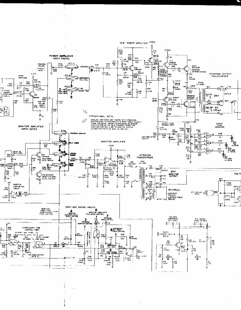
Step 3. Remove jumper connected across wire wrap terminals T58 and T59.These terminals are located adjacent to socket RY2. Refer toattached Schematic Diagram KC-1362 for circuit details.
3.6 Modification For Single-Channel System Operation
Unshielded speaker lines were often used in older buildings. Ifthese are encountered,single-channel system,
it may be desirable to operate the MCI350 as ainstead of incurring the cost of rewiring the
building with shielded cable. Operation of a single-channel systemtemporarily prevents the distribution of program material to roomswhile an intercom conversation is proceeding.
PAGE 5

TO make modification:
Step 1. Access the MC1350 Circuit board as described in Paragraph
Step 2. Install a jumper across wire wrap terminals T19 and T20.terminals are located about two inches behind the MONITOR
3.3.
These
PROGRAM control. Refer to attached Schematic Diagram KC-1362for circuit details.
3.7 Conversion For 5 Volt (45 Ohm) Output_-__l_--_-_)- -
The MCI350 is shipped from the factory wired for 25 Volt constant-voltage outpu-t. If 5 Volt (45 Ohm) output is required:
Step 1. Access the MCI350 circuit board as described in Paragraph 3.3.
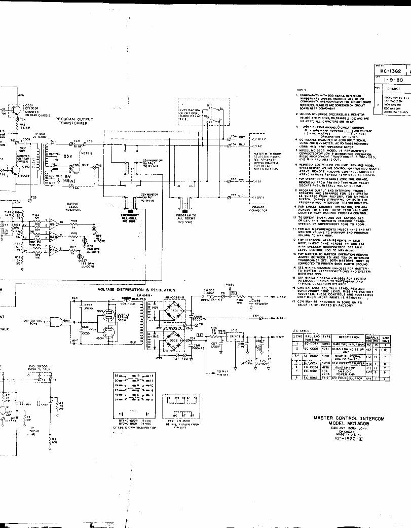
Step 2. Change the secondary connections of chassis-mounted programoutput transformer XF502 as shown in Chart 1, below. Refer toattached Schematic Diagram KC-1362 for circuit details.
Chart 1. Program Transformer Output Connections.
Wire Color 25V Jumper Change To 5V Jumper_--- I_ - _ - - - - - -Blue T56 to T69 T56 to T67
White T53 to T68 T53 to T66
Step 3. Change the secondary connections of circuit-board mounted inter-corn transformer XF2 as shown in Chart 2. Refer to the attachedSchematic Diagram KC-1362 for circuit details.
Chart 2. Intercom Transformer Output Connections.
Wire Color 25V Jumpers Change to 5V Jumpers- _-Orange T39 to T35 T39 to T33
White T 4 0 to T36 T 4 0 to T34
3.8 Interface For Multiple-Master Intercom Operationn_______________
Intercom operation with multiple masters requires interface to wirewrap terminals provided on the amplifier circuit board, and modifica-tions to the room selector panel. Required interface is described inthis paragraph. Use of wiring interface and needed room selectorpanelmodifications are given in a subsequent paragraph. Refer to attachedMiltiple Masters Connections Diagram KM-0535 for circuit details.
Step 1. Locate wire wrap terminals T45 and T48, adjacent to listen/talkrelay RYl. These terminals provide the multiple master inputconnections to the amplifier for master operation. Two ten-inch long wires are needed; connect one wire to each terminal, lT45 and T48.
PAGE 6

Step 2.
Step 3.
Step 4.
step 5.
Step 6.
Make three or four twists throughout the length of the wires.Route twisted wires along side of chassis and insert throughaccess space provided between rear edge of circuit board andchassis bottom.
Locate wire wrap terminals T37 and T38, adjacent to listen/talk relay RYl. These terminals provide the multiple masteroutput connections for the C BUSS on the room selector panel.Connect two two-foot long wires, one wire to each of theseterminals.
Make several twists throughout the length of the wires. Routetwisted wires along side of chassis and insert through accessspace provided between rear edge of circuit board and chassisbottom.
Locate wire wrap terminals T30 and T31, adjacent to intercomtransformer XF2. Remove the jumper connected between T30 andT31 to isolate the center tap of XF2 from circuit common.
Connect each master used in the master-to-master configurationto a proven good earth ground. It's recommended that theshield of the wire pair from Master #l to Master #2 be con-nected to chassis ground at Master #2.
3.9 Remounting MCI350 In Cabinet (Desk-Top Models Only)
Cabinet should be upside-down for remounting the MC1350 and theswitchbanks in the subsequent paragraphs. Place the MCI350 on theinside of the cabinet. Secure the MCI350 to the cabinet using thefour screws previously removed.time,
Don't install dress panel at thisas controls accessible only through front chassis may have to
be adjusted when setting initial levels.
3.10 Rack-Mounting Or Turrent-Mounting MCI350-
If rack-mounting the unit, forced air ventilation is recommendedfor an enclosed equipment rack where the combined rated output powerof all equipment exceeds 250 watts RMS, or the input power to therack from the 60 Hz power line exceeds 500 watts: or where there isthe possibility of "hotspots" due to restricted air flow.
CAUTION
Failure to observe the above precautions couldresult in damage due to overheating, or couldcause a possible fire hazard.
PAGE 7

If turrent-mounting the unit, use one of the upper positions inthe turrent so that there is sufficient clearance beneath the chassisto make switchbank interconnections. Make sure that the mounting posi-tion selected is deep enough to accommodate the 10½" depth of the unit,plus the additional space needed to install field wiring and performroutine maintenance functions.
CAUTION
Observe all safety precautions given abovefor rack-mounted units. Failure to observethese precautions could result in damage dueto overheating, or could cause a possiblefire hazard.
Install chassis using the following procedure:
Step 1. Insert the four #lO TINNERMAN-type clips supplied with the unitover the corresponding mounting holes in the channel rails forthe selected mounting position. Smooth side of clip must facetowards outside of channel rail.
Step 2. Secure the MCI350 chassis to the channel rails using the four#l0-½" sheet metal screws supplied. Don't install dress panelat this time, as controls accessible only through front chassismay have to be adjusted when setting initial levels.
3.11 Room Selector Panel Modifications
MASTERROOM 4
\ I1
MULTIPLEMASTER REMOTE
ROOM 3
Figure 1. Sample Multiple Master Intercom System
PAGE 8

3.11.1 System Definitions and Capabilities----_c_-___-__-_--_
For intercom operation, the MCI350 is considered to be a masterand classrooms to be remotes. When only one MCI350 is used in thesystem, the configuration is called a single master with multipleremotes intercom system. This is the typical intercom system andrequires no equipment modifications, as shipped from the factory.
A multiple master system is shown in Figure 1. Each master inthis system is capable of operating with several remotes. Multiplemaster systems require modifications to the associated room selectorpanels dependent upon how the included remotes are used in the system.When a remote can communicate only with one master, it is called adedicated remote. When all masters in the system are operated witheither dedicated remotes or no remotes, the only modification requiredis to split the C BUSS on the room selector panel. This isolates theC lines between masters and remotes. In a dedicated remote system,both intercom and program all-call are possible without additionalmodification.
When a remote can communicate with more than one master, it iscalled a multiple-master remote and is used in a system configurationcalled an intermix intercom system. For intermix systems, the roomselector panel must be modified by: (1) splitting the C BUSS, and (2)completely removing both OFF BUSSES. In an intermix system, intercomall-call is possible only if a special buss gathering relay is used.Contact Rauland-Borg Sales Engineering for modification details.Program all-call is not practical as lock-out relays would be required.
3.11.2 How To Split C BUSS- - - - - - - - -
Split the C BUSS on the associated room selector panel at theswitch position correlating to the number of outlying masters used inthe system. For example: if four outlying masters are used in thesystem, split the C BUSS at switch number four. Outlying masters mustalways be assigned the low-numbered switch positions. Both C BUSSplating strips run along the top of the room selector circuit board,with Cl on the front of C2 on the rear of the board.
On the SWL25 Room Selector Panel, some disassembly is requiredsince the C BUSS can not be readily accessed. Remove metal spacerbaron rear of unit. Remove two screws securing rear circuit board tomounting frame. Swing rear board away from front board using the wirejumpers along the bottom of both boards as a hinge. Refer to attachedInstruction Manual KI-1200 for circuit details.
3.12 Adding Second Or Third Room Selector Panels
The second room selector panel can be installed either below thefirst room selector panel in the DIR350 or DIR350L Systems, or with athird room selector panel in a separate PCC300A Cabinet. In eithercase, the physical installation is the same. Remove blank dress panelfrom selected mounting position, if not previously removed. Remove thetwo blank panel supports mounted to the channel rails. Make modifi-cations to the room selector panel as required per Paragraph 3.11.
PAGE 9

Install the room selector panel using the mounting hardware suppliedwith the panel. A second PCC300A Cabinet is required for mounting thethird room selector panel. Follow the afore-referenced instructionsfor its installation.
3.13 Cabling Between MCI350 and One Room Selector Panel
Prewired cabling is provided with the MCI350 for direct plug-into one SW25 or SWL25 Room Selector Panel. Some cabling modificationsare required when more than one room selector panel is used in thesystem. Interface of the MCI350 with equipment other than the SW25 orSWL25 requires custom-made cabling.
Step 1. Insert the ORANGE four-contact plug onto the A-OFF terminalpins provided on one end of the room selector panel. Properplug orientation is to have the violet wire correspond withOFF-l.
Step 2. Insert the RED five-contact plug onto the C-G (SW25) or C-G-L-K (SWL25) terminal pins on the other end of the roomselectorpanel. Proper plug orientation is to have the red wire of theshielded cable correspond with C2.
3.14 Connections To Two Room Selector Panels
In multiple room selector panel installations, paralled connec-tions must be made to each panel. Connections for the C-G lines andthe L-K lines on the SWL25 are made to the screw terminals provided onthe rear of the MC1350. Connections for the A-OFF lines are made bysplicing into the existinq cable. Refer to attached Wiring DiagramKM-0540
Step 1.
while performing the following steps.
Step 2.
Step 3.
Insert the prewired ORANGE four-contact plug onto the A-OFFterminal pins provided on one end of the second room selectorpanel. Proper plug orientation is to have the violet wirecorrespond with OFF 1.
Make parallel connections to the corresponding terminal pinson the first room selector panel using the unwired ORANGEinsulation-piercing connector provided with the.second roomselector panel. This connector may have to be modified bycutting through the shell on one side, if it is notcompatiblewith loop-through splicing of the interconnecting wires.
Insert the prewired RED five-contact plug onto the C-G (SW25)or C-G-L-K (SWL25) terminal pins on the other end of the firstroom selector panel. Proper plug orientation is to have thered wire of the shielded cable correspond with C2.
PAGE 10

step 4. To make parallel connections for the C-G (SW25) and the C-G-L-K(SW25) lines, a cable must be fabricated long enough to reachfrom the screw terminals on the rear of the MCI350 to theunusedterminal pins on the other end of the second room selectorpanel. Use the unwired RED connector provided with the secondroom selector panel and suitable wires to make the cable.Install #6 spade lugs on the opposite end of the fabricatedcable for termination with the MC1350.
Step 5. Insert RED connector onto terminal pins on the end of thesecondroom selector panel. Proper plug orientation is to have the redwire of the shielded cable correspond with C2. Connect otherend of cable to screw terminals on the rear of the MCI350, asshown below.
ScrewTerminal
SWL25 SW25Function Function
Cl
c2
GND
+PSL25
-PSL25
Cl Cl
c2 c2
G G
L --
K --
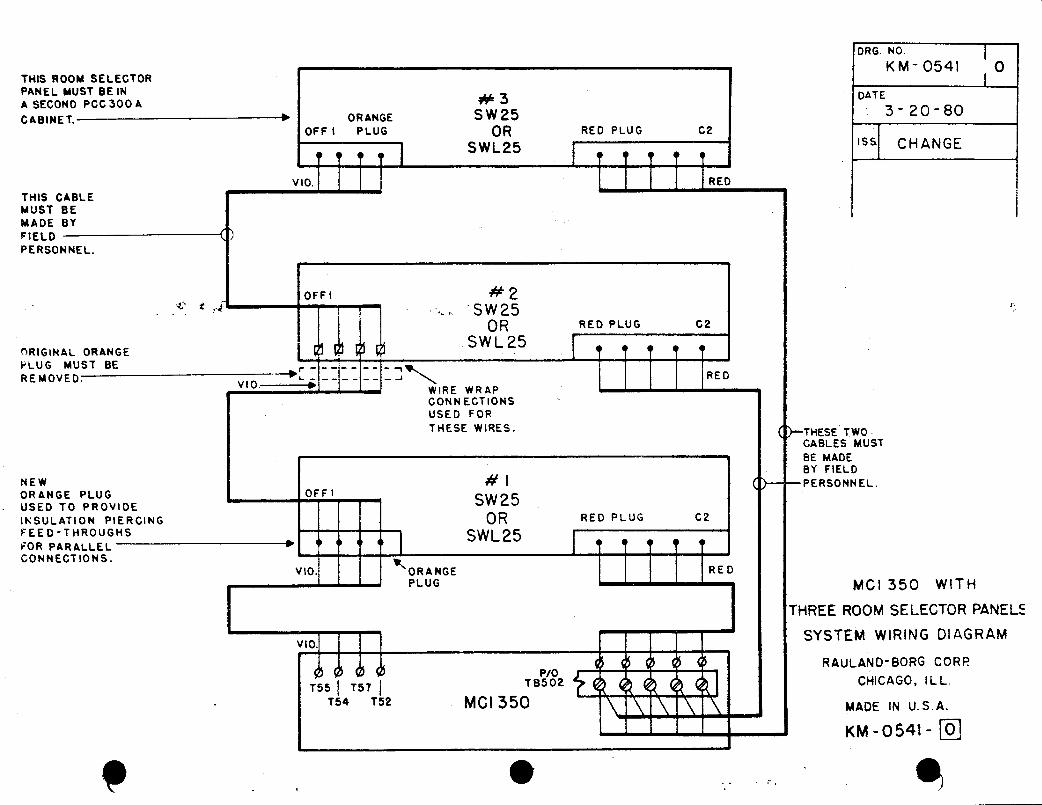
3.15 Connections To Three Room Selector Panels
In multiple room selector panel installations, parallel connec-tions must be made to each panel. Connections for the C-G lines andthe L-K lines on the SWL25 are made to the screw terminals provided onthe rear of the MC1350. Connections for the A-OFF lines are made bysplicing into the existing cable. Refer to attached Wiring DiagramKM-0541 while performing the following steps.
Step 1.
Step 2.
Locate the ORANGE plug on the end of one of the cables providedwith the MC1350. Remove the ORANGE plug by cutting the wiresclose to the plug.
Connect the four wires previously terminated at the orangeplugto the second room selector panel by wire wrapping to thefollowing terminals:
Wire Color SW25/SWL25 Terminal
Violet OFF 1
Gray OFF 2
Blue A2
White Al
PAGE 11
Step 3. Make parallel connections to the corresponding terminal pinson the first room selector panel using the unwired ORANGEinsulation-piercing connector provided with the second roomselector panel. This connector may have to be modified bycutting through the shell on one side, if it is not compatiblewith loop-through splicing of the wires.
Step 4. Make parallel connections from the second to the third roomselector panels, using a specially fabricated cable. Use theunwired ORANGE connector provided with the third room selectorpanel and suitable wire to make the cable. Leave the oppositeend of this cable unfinished.
Step 5. Insert the ORANGE connector onto the A-OFF terminal pins onthe end of the third room selector panel. Proper plug orien".tation is to have the violet wire correspond with OFF 1. Ter-minate other end of cable to the second room selector panel bywire wrapping to the qorresponding terminals pins used inStep 2 above.
Step 6. Two additional cables will have to be fabricated using the REDconnectors provided with the second and third room selectorpanels. Connect these cables from the MCI350 tothird room selector panels.
3.16 Connections To More Than-Three Room Selector Panels
the secondand
For intercom systems where program all-call and emergency all-call are not required, more than three room selector panels may beused. Parallel connect these room selector panels to the third roomselector panel and to the MCI350 as if adding a second panel. Referto paragraph 3.14 for procedural guidelines.
3.17 Equipment Location Considerations For Desk-Top Models
Good judgement must be used when selecting the equipment location.Consider user safety, environmental conditions, and accessibility toequipment controls. Never use a location where the equipment is sub-jected to "hotspots" or "coldspots", or widely changing temperatures.Never place the unit on a soft, yielding surface that could impedeairflow underneath or around the sides of the cabinet.
CAUTION
Failure to observe the aboveprecautions could resul-t indamage due to over-heating,or could cause a possiblefire hazard.
PAGE 12

3. 18 Wiring Guide1 ines-___i--....___--.-.-______
Local codes a n d ordinances should be checked before permanent acpower lines, if required, are installed and terminated at the equip-ment . If using conduits for cable runs, separate conduits should beused for AC power lines a n d audio lines. To minimize the possibilityof high frequency oscillations, high level audio lines should be keptas far as possible from microphone input lines. Good practicedictatesthat the microphone lines be shielded and preferably run in a separateconduit.
WARNING
Make AC power connections to theseamplifiers only after all otherconnections have been made.
When using more than one speaker in the same room, make sure thespeakers are correctly phased to prevent low frequency cancellation.For a parallel-wired system, make sure all system components are con-nected to the same polarity; speaker wires to speaker terminals andline-matching transformers to speaker terminals. For a series-wiredsystem, make sure all system components are connected to oppositepolarities, from one item to the next item.
In intercom systems using voice-call origination, one twisted-pair shielded cable is "looped" between all classrooms equipped withvoice call origination switches before it is terminated at' the MCI350.In some installations, it may be easier or less costly to make the callorigination connections directly to certain classrooms; so called"home-run" connections.
3.19 Microphone Input Connections--
Follow the wiring guidelines given in Paragraph 3.18 beforemakingmicrophone connections. Make connections to the MICl and MIC 2 screwterminals shown in the following chart using appropriate space lugs.Both microphone inputs must be low impedance.
Screw Terminal Low-Impedance Microphone
(Hi)L_GNDSignalCable ShieldSignal
3.20 Auxiliary Input Connections--_--_-- _..-_-~--.----
Follow the wiring guidelines given in Paragraph 3.18 beforemakingauxiliary input connections. The AUX and TAPE/TUNER jacks accept anRCA-type phono-plug for unbalanced input sources. High impedance aux-iliary sources are acceptable. Applicable equipment are: record -changer, AM-FM tuner, tape player, etc.
PAGE 13

3.21 Remote Volume Control. Connections
Make the connections shown in the following detail to the MICREMOTE VOLUME and COM screw. terminals using #6 spade lugs.
NOT CONNECTED MODEL 47RVC
MIC REMOTE REMOTE VOLUME CONTROL
(REAR VIEW)
3.22 Time Clock Closure Connections
Use only a dry-contact closure a energize the clock relay withinthe MC1350. If the programmed time-change clock provides a switchedvoltage for time-change activation, use a suitable slave relay toproduce the required closure. Connect the dry-contact closure acrossthe CLOCK screw terminals using #6 spade lugs.
3.23 Intercom Voice-Call Origination Connections
Step 1. Follow the wiring guidelines given in Paragraph 3.18 beforemaking voice-call origination connections.
Step 2. Connect the voice-call origination cable to the C BUSS screwterminals shown in the following chart using #6 spade lugs.
C BUSS Terminals . Function- - -
Cl Voice Call-Inc2 Voice Call-InGND Cable Shield
3.24 Room Speaker And Light Call-In ConnectionsI~-Connect speaker and light call-in lines to the room selectorpanel
following the procedure given in attached Instruction Manual KI-1200.If the SWL25 Room Selector Panel is used, verify that Power SupplyPSL25 is securely mounted to the bottom of the MC1350. Also, verifythat the power supply is connected to -the PSL25 + and - screwterminals.(Positive wire is marked with a colored dot or tracer stripe.)
3.25 Cabinet Reassembly
Step 1. Place back panel on cabinet and secure with the screws origi-nally removed.
PAGE 14


4.3 INTERCOM TALK LEVEL Control R30--_l___-~
Step 1. In a distant room,in NORMAL position,
have assistant place call origination switchif the room is so equipped.
Step 2. Place appropriate room selector switch in the PROGRAM Cposition.
Step 3. Depress and hold t h e PRESS-TO-TALK/release to listen switch.Talk into the monitor speaker grille using your normal voicelevel.
Step 4. Adjust INTERCOM TALK LEVEL Control R30 to obtain the desiredroom speaker volume level.
Step 5. Place appropriate rodm selector switch in the OFF position.
4.4 SUPERVISORY TONE LEVEL Control R126-
Step 1. In a distant room,in NORMAL position,
have assistant place call origination switchif the room is so equipped.I.
Step 2. Place appropriate room selector switch in theAbout every thirteen seconds, the supervisorysound in the selected room.
Step 3. Adjust SUPERVISORY TONE LEVEL Control R126 toroom speaker volume level.
Step 4. Place appropriate room selector switch in the
5. OPERATION
PROGRAM C position.tone will briefly
obtain thedesired
OFF position.
5.1 Introduction
Equipment operation is straightforward using the color coordinatedguidelines and condensed instructions provided on the equipment. Callsfrom rooms will either be by voice when the SW25 is used, or by thesounding of a tone and an illuminated lamp when the SWL25 is used. Onceyou have operated the equipment as a system,as simple as A.B.C. to do so.
you will find that it is
5.2 How To Use The Output Level Indicators- - -
These indicators provide visual monitoring of the relative audiooutput from the program amplifier. PROPER output level is indicatedwhen the TWO GREEN lamps are on. This condition permits optimum oper-ation of the program amplifier for undistorted sound amplification.The red lamp may flash occasionally on voice peaks: this is a normalcondition and indication. EXCESSIVE output level is indicated whenthe TWO GREEN and the RED lamps are on. This condition can cause over-driving of the program amplifier producing much distortion. If exces-sive audio output is continuously indicated, have the equipment checkedby a Rauland-Borg serviceman for possible malfunction or improperlymade input level adjustments.
PAGE 16
LOW output is indicated when only the FIRST GREEN lamp is on. Thiscondition may produce low or distorted output for the program ampli-fier. If low output is continuously indicated, have the equipmentchecked for proper operation.
5.3 Remotely Controlled Microphone Volume
This mode of operation is an option that may be used in your soundsystem. Caution must be used with remotely controlled volume as im-proper operation could prevent transmission of microphone audio through-out the system. Setting the remote volume control to OFF blocks trans-mission of audio through both microphone channels (MICl and MIC2).Always set the remote volume control to MAX (not OFF) when leaving thecontrol unattended.
6.
6.1
MAINTENANCE
Simulating Classroom Selection
A classroom selection can'be easily simulated when the MCI350MasterControl Intercom Panel is operated without a room selector panel, asmay be required for servicing in the shop. Simply, jumper the "C" bussusing a 1.2 k ± 5%, ½ watt resistor'across the Cl and C2 screw terminals.
6.2 Monitoring Without Supervisory Alerting Tone Transmissions
The periodic supervisory tone transmissions that normally occurduring the intercom listening mode may be objectional. These trans-missions can be defeated by adding a jumper across C26 or C27 in thesupervisory tone timer circuitry. Refer to attached Schematic DiagramKC-1362 for circuit details.
PAGE 17