ceiling connector assembly installation - · pdf fileceiling connector assembly installation...
TRANSCRIPT

860634932
Issue 1, May 2017
www.commscope.com
Ceiling Connector Assembly Installation
© 2017 CommScope, Inc.
All rights reserved
This product is covered by one or more U.S.
patents or their foreign equivalents. For patents, see
www.commscope.com/ProductPatent/ProductPatent.aspx
Page 1 of 4
For RoHS Inquiries:CommScope Inc.Corke Abbey, BrayCo. Dublin, IrelandAttn: Legal Department
General
These instructions provide the installation procedure for the Ceiling
Connector (760234921) and cord assemblies incorporating the ceiling
connector assembly. See the CommScope Product Catalog for available
cord configurations.
How to Contact Us
To find out more about CommScope® products, visit us on the web at
www.commscope.com/
For technical assistance, customer service, or to report any
missing/damaged parts, visit us at
http://www.commscope.com/SupportCenter
Tools Required
Cable jacket scoring tool (such as Xcelite® 2CSKY or JOKARI® No.1-Cat)
Flush-cutting wire cutters (such as Xcelite MS545JV)
Tongue-and-groove pliers (optional)
Flat-blade screwdriver
Parts List
Verify parts against the parts list below:
Quantity Description
1 Ceiling connector assembly
2
2
Ceiling connector cap (one pre-installed in cord assemblies)
Small cable tie (one pre-installed in cord assemblies)
Ceiling Connector

860634932
Instruction Sheet www.commscope.com
Page 2 of 4
Cable Termination
1. Remove approximately two inches (50mm) of cable jacket. Bend the pairs out of the way and cut away any
separator device. Arrange the wires in order – BLUE, ORANGE, GREEN, BROWN – with the blue and
brown pairs bent 90° in opposite directions, as shown in image 1, below.
2. Insert the cable into the connector and push it tight against the middle pair separator, shown in image 2.
3. Add twist to each pair so that the proper wire is on top over the pair gate, and place it into the gate.
IMPORTANT: The two sides of the connector are color marked differently. The colored wire must be on top
in the gate with the color markings positioned to the left as shown in 3a. On the side with the color markings
positioned to the right (3b), the white/light wire must be on top in the gate.
Middle pairseparator
Colored wireon top in gate.
Color markson left.
White/light wireon top in gate.
Color markson right.
Orange
Blue
Green
Brown
2 1
3a 3b

www.commscope.com 860634932
Instruction Sheet
Page 3 of 4
4. Unwind and route each wire into its respective slot (colored wire by color marking), pulling the wire
underneath the retention barbs at the end of each slot. Start with the center pairs and keep the cable tight
against the middle pair separator. Route the outside pairs underneath the hooks as shown in image 4.
5. Trim pair separator tapes (if present) directly after the pair gates as shown in image 4 and trim the wires
flush with the end of the wire slots, image 5.
6. Optionally, install a small cable tie for strain relief (6a). Cut the excess cable tie length flush and position the
cable tie head to either side to avoid interference with the cap (6b).
7. Install a cap over the wires and squeeze it lightly to partially seat the wires.
Note: Repeat steps 1-7 to terminate the other side of the connector, if necessary.
8. Squeeze the caps to engage retention snaps on both sides of each cap as shown in image 8. This may be
done by hand or with tongue-and-groove pliers. If using pliers, squeeze along the ribbed surface.
Outside pairsunderneathhooks.
Trim separatortapes(if present).
Unwind androute eachwire into slot.
Trim wiresflush.
Note: Make sure thatall wires are fully seatedwithin the wire slots.
Cable tie headto either side.
4 5 6a
6b 7 8
860634932
Instruction Sheet www.commscope.com
Page 4 of 4
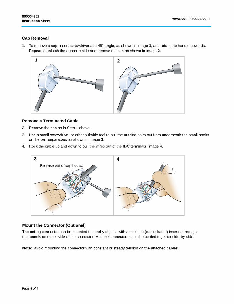
Cap Removal
1. To remove a cap, insert screwdriver at a 45° angle, as shown in image 1, and rotate the handle upwards.
Repeat to unlatch the opposite side and remove the cap as shown in image 2.
Remove a Terminated Cable
2. Remove the cap as in Step 1 above.
3. Use a small screwdriver or other suitable tool to pull the outside pairs out from underneath the small hooks
on the pair separators, as shown in image 3.
4. Rock the cable up and down to pull the wires out of the IDC terminals, image 4.
Release pairs from hooks.
Mount the Connector (Optional)
The ceiling connector can be mounted to nearby objects with a cable tie (not included) inserted through
the tunnels on either side of the connector. Multiple connectors can also be tied together side-by-side.
Note: Avoid mounting the connector with constant or steady tension on the attached cables.
1 2
3 4