cee rotax max challenge special technical regulation 2019 ... · cee rotax max challenge special...
TRANSCRIPT
1
CEE Rotax MAX Challenge Special Technical
Regulation 2019
1. General The RMC Technical Regulations 2019 replace the RMC Technical Regulations 2018. Anything which is not expressly allowed in the technical regulations is forbidden. The English language is the authentic version.
1.1. Categories
125 Micro Max
125 Mini Max
125 Junior MAX
125 MAX
125 MAX DD2/ DD2 Masters
Note: The 125 Junior MAX engine is the basis for the engine configurations 125 Micro MAX and 125 Mini MAX. Only the deviations for 125 Micro MAX and 125 Mini MAX from the standard Technical Regulation for the 125 Junior MAX engine are defined.
1.2. Amount of equipment
For each RMC race event (from qualifying practice to the final) following
maximum amount of equipment is allowed:
1 chassis
1 sets of dry tires + 1 spare tire
wet tires are free number of pieces
2 engines
2. Equipment
2.1. Chassis 125 Micro MAX, 125 Mini MAX
For national RMC's any chassis sanctioned by an authorized Rotax distributor is allowed with a wheel base of 950 mm. Front brakes are not allowed.
2
2.2. Chassis 125 Junior MAX and 125 Senior MAX
Front brakes are not allowed. For national RMC's any chassis sanctioned by an authorized Rotax distributor is allowed with a wheel base of 1040 mm. Maximum diameter of rear axle = 50 mm, minimum wall thickness according to CIK-FIA rules. At IRMCE chassis with a valid CIK-FIA homologation only are allowed. Any brake system must have a valid CIK-FIA homologation.
2.3. Chassis 125 MAX DD2/DD2 Masters
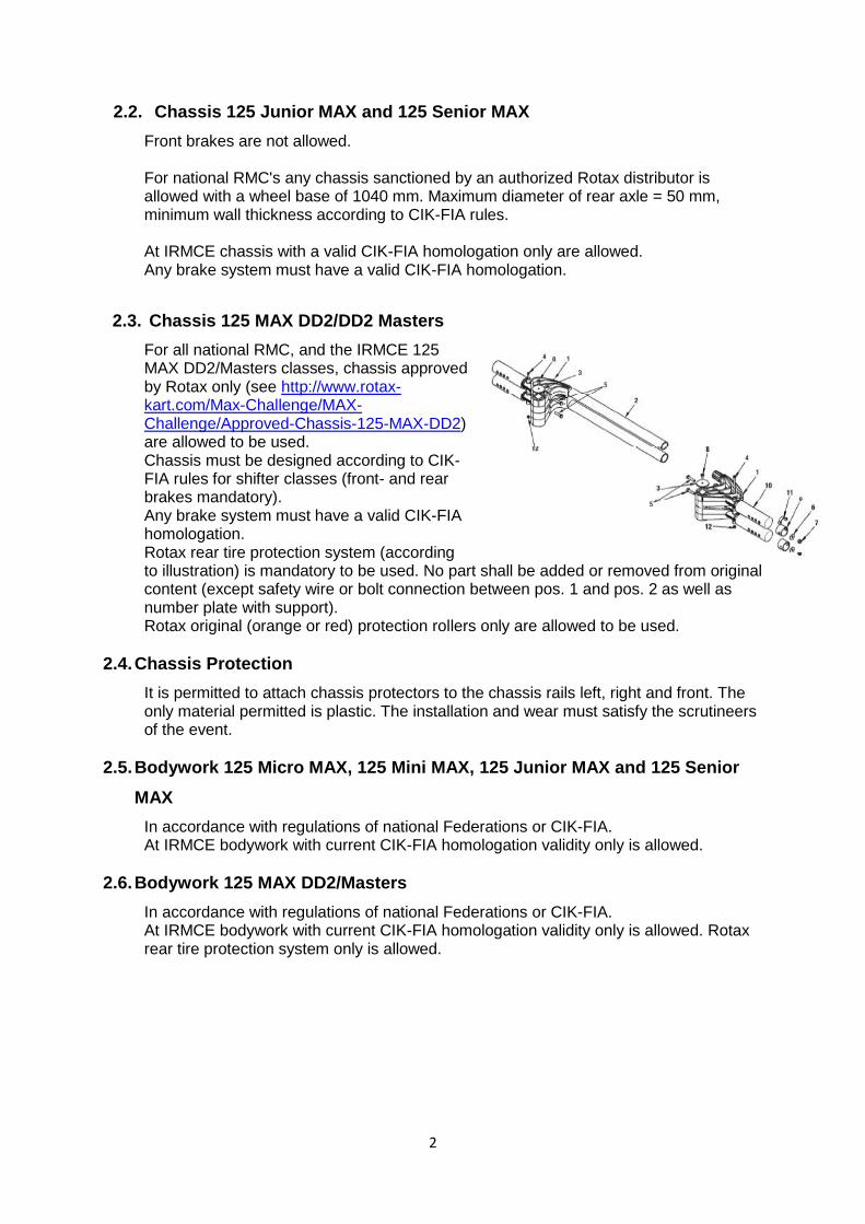
For all national RMC, and the IRMCE 125 MAX DD2/Masters classes, chassis approved by Rotax only (see http://www.rotax-kart.com/Max-Challenge/MAX-Challenge/Approved-Chassis-125-MAX-DD2) are allowed to be used. Chassis must be designed according to CIK-FIA rules for shifter classes (front- and rear brakes mandatory). Any brake system must have a valid CIK-FIA homologation. Rotax rear tire protection system (according to illustration) is mandatory to be used. No part shall be added or removed from original content (except safety wire or bolt connection between pos. 1 and pos. 2 as well as number plate with support). Rotax original (orange or red) protection rollers only are allowed to be used.
2.4. Chassis Protection
It is permitted to attach chassis protectors to the chassis rails left, right and front. The only material permitted is plastic. The installation and wear must satisfy the scrutineers of the event.
2.5. Bodywork 125 Micro MAX, 125 Mini MAX, 125 Junior MAX and 125 Senior
MAX
In accordance with regulations of national Federations or CIK-FIA. At IRMCE bodywork with current CIK-FIA homologation validity only is allowed.
2.6. Bodywork 125 MAX DD2/Masters
In accordance with regulations of national Federations or CIK-FIA. At IRMCE bodywork with current CIK-FIA homologation validity only is allowed. Rotax rear tire protection system only is allowed.
3
2.7. Tires
At all RMC and IRMCE following tires have to be used Front tyre Rear tyre 125 Micro MAX Dry Mojo C2 4.0 x 10.0 5.0 x 11.0 Wet Mojo W3 4.5 x 10.0 – 5 4.5 x 10.0 – 5
125 Mini MAX Dry Mojo C2 4.0 x 10.0 5.0 x 11.0 Wet Mojo W3 4.5 x 10.0 – 5 4.5 x 10.0 – 5
125 Junior MAX Dry Mojo D2 4.5 x 10.0 – 5 7.1 x 11.0 – 5 Wet Mojo W3 4.5 x 10.0 – 5 6.0 x 11.0 – 5
125 Senior MAX Dry Mojo D5 4.5 x 10.0 – 5 7.1 x 11.0 – 5 Wet Mojo W3 4.5 x 10.0 – 5 6.0 x 11.0 – 5
125 MAX DD2/Masters Dry Mojo D5 4.5 x 10.0 – 5 7.1 x 11.0 – 5 Wet Mojo W3 4.5 x 10.0 – 5 6.0 x 11.0 – 5
Strictly no modifications or tire treatment allowed. Recommended equipment to detect tire treatment is Mini-RAE-Lite. Threshold value of maximum 4 ppm is recommended. Tires must be mounted according to the sense of rotation defined on the tire.
2.8. Data acquisition
Systems which permit the reading/recording of following
data are allowed.
All telemetry system is allowed Connection of the data acquisition system to the original Rotax battery is allowed.
2.9. Composite materials
Composite materials (carbon fiber etc.) are banned except for the seat and
the floor tray. Alloys from different metals/substances are not considered as
composite materials.
2.10. Safety equipment
For RMC overalls, helmets, kart shoes, gloves and other kind of driver protection
must comply with the regulations of the national Federation or CIK-FIA.
For IRMCE and the RMCGF article 3 of CIK-FIA technical regulations apply.
4
2.11. Fuel/Oil
Unleaded fuel 95 octane’s.
only XPS-KARTTEC 2-stroke oil ( ROTAX PART NO. 297461 ) can be used int he
CEE events!
2.12. Advertising on engines
No sponsor stickers are allowed on the engine and engine accessories, except ROTAX, BRP, Mojo, XPS, Original SODI KART badges and the following plates attached to the cylinder.
3. Engine sealing, Scrutinizing
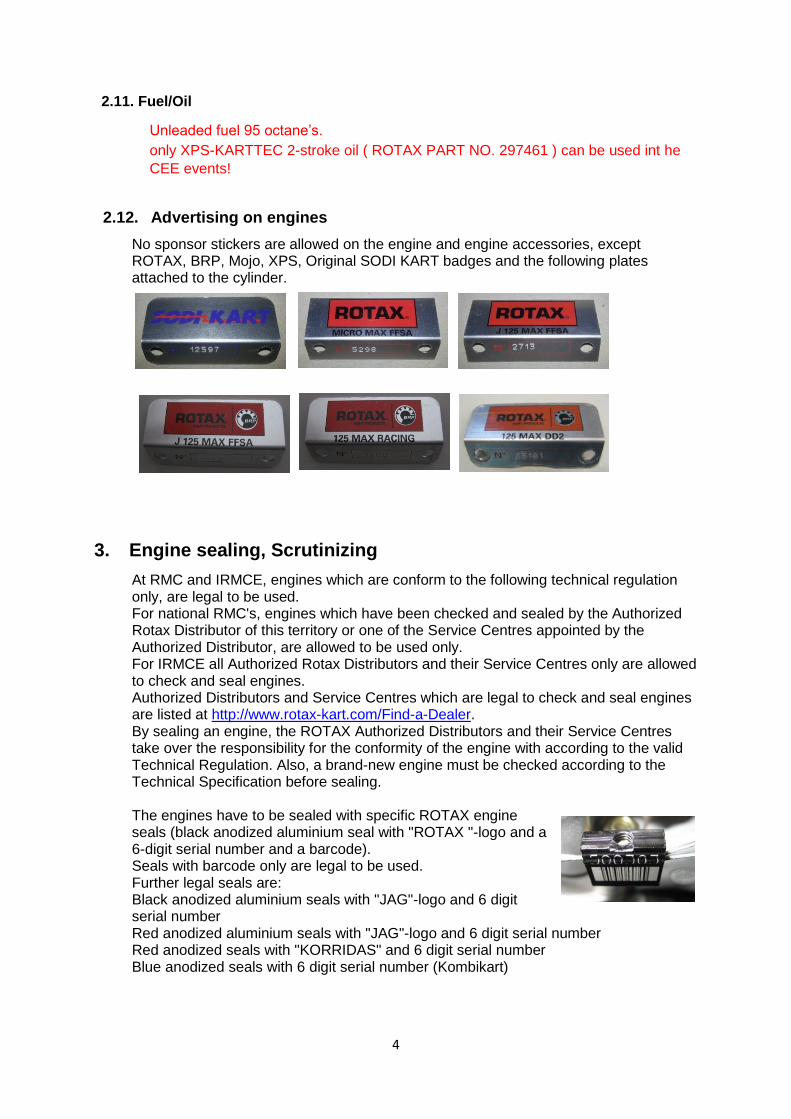
At RMC and IRMCE, engines which are conform to the following technical regulation only, are legal to be used. For national RMC's, engines which have been checked and sealed by the Authorized Rotax Distributor of this territory or one of the Service Centres appointed by the Authorized Distributor, are allowed to be used only. For IRMCE all Authorized Rotax Distributors and their Service Centres only are allowed to check and seal engines. Authorized Distributors and Service Centres which are legal to check and seal engines are listed at http://www.rotax-kart.com/Find-a-Dealer. By sealing an engine, the ROTAX Authorized Distributors and their Service Centres take over the responsibility for the conformity of the engine with according to the valid Technical Regulation. Also, a brand-new engine must be checked according to the Technical Specification before sealing. The engines have to be sealed with specific ROTAX engine seals (black anodized aluminium seal with "ROTAX "-logo and a 6-digit serial number and a barcode). Seals with barcode only are legal to be used. Further legal seals are: Black anodized aluminium seals with "JAG"-logo and 6 digit serial number Red anodized aluminium seals with "JAG"-logo and 6 digit serial number Red anodized seals with "KORRIDAS" and 6 digit serial number Blue anodized seals with 6 digit serial number (Kombikart)
5
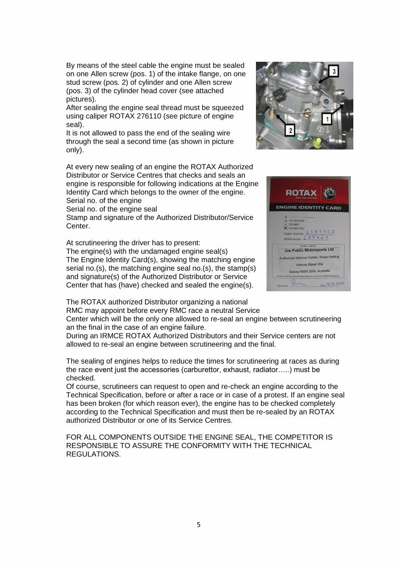
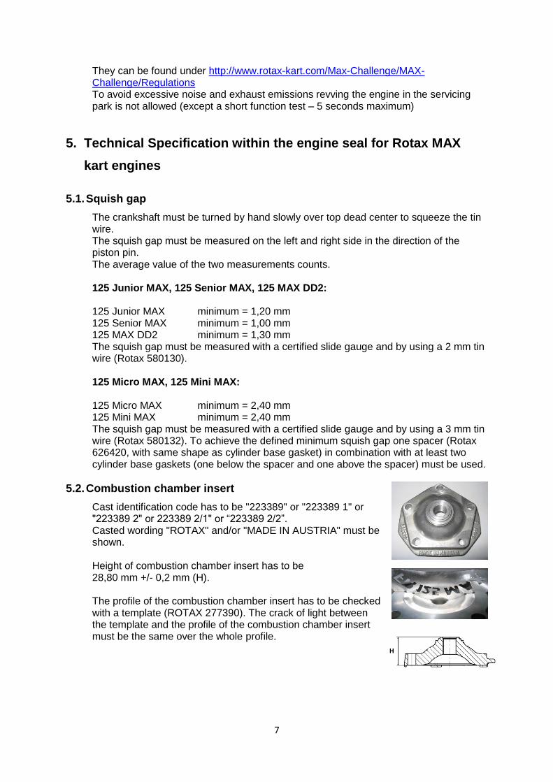
By means of the steel cable the engine must be sealed on one Allen screw (pos. 1) of the intake flange, on one stud screw (pos. 2) of cylinder and one Allen screw (pos. 3) of the cylinder head cover (see attached pictures). After sealing the engine seal thread must be squeezed using caliper ROTAX 276110 (see picture of engine seal). It is not allowed to pass the end of the sealing wire through the seal a second time (as shown in picture only). At every new sealing of an engine the ROTAX Authorized Distributor or Service Centres that checks and seals an engine is responsible for following indications at the Engine Identity Card which belongs to the owner of the engine. Serial no. of the engine Serial no. of the engine seal Stamp and signature of the Authorized Distributor/Service Center. At scrutineering the driver has to present: The engine(s) with the undamaged engine seal(s) The Engine Identity Card(s), showing the matching engine serial no.(s), the matching engine seal no.(s), the stamp(s) and signature(s) of the Authorized Distributor or Service Center that has (have) checked and sealed the engine(s). The ROTAX authorized Distributor organizing a national RMC may appoint before every RMC race a neutral Service Center which will be the only one allowed to re-seal an engine between scrutineering an the final in the case of an engine failure. During an IRMCE ROTAX Authorized Distributors and their Service centers are not allowed to re-seal an engine between scrutineering and the final. The sealing of engines helps to reduce the times for scrutineering at races as during the race event just the accessories (carburettor, exhaust, radiator…..) must be checked. Of course, scrutineers can request to open and re-check an engine according to the Technical Specification, before or after a race or in case of a protest. If an engine seal has been broken (for which reason ever), the engine has to be checked completely according to the Technical Specification and must then be re-sealed by an ROTAX authorized Distributor or one of its Service Centres. FOR ALL COMPONENTS OUTSIDE THE ENGINE SEAL, THE COMPETITOR IS RESPONSIBLE TO ASSURE THE CONFORMITY WITH THE TECHNICAL REGULATIONS.

6
4. Engine modifications, repairs and additions
4.1. Modifications
Neither the engine nor any of its ancillaries may be modified in any way. "Modified" is defined as any change in form, content or function that represents a condition of difference from that originally designed. This is to include the addition and/or omission of parts and/or material from the engine package assembly unless specifically allowed within these rules. The adjustment of elements specifically designed for that purpose shall not be classified as modifications, i.e. carburettor and exhaust valve adjustment screws. The repair of a thread on the crankcase (maximum of three threaded holes per crankcase) using a "heli-coil" or similar is allowed. Exception: The threads located under the crankcase to fix the crankcase on the engine mount may be repaired as needed. The repair of a thread on the cylinder (maximum of three threaded holes per cylinder) using a "heli-coil" or similar is allowed. Genuine ROTAX components only that are specifically designed and supplied for the 125 Micro MAX, 125 Mini MAX, 125 Junior MAX, the 125 Senior MAX and the 125 MAX DD2 engine are legal, unless otherwise specified. ANYTHING WHICH IS NOT EXPRESSLY ALLOWED IN THE TECHNICAL REGULATIONS IS FORBIDDEN.
4.2. Internal additions
No additional material may be added except in the case of engine repairs and shall only restore the engine or components to original specifications. The use of thermal barrier coatings/ceramic coatings on or in the engine and on or in the exhaust system is prohibited. The use of anti-friction coatings in or on the engine/engine components is prohibited.
4.3. Legal additions
Chain guard, engine mount, temperature gauge and tachometer/hour meter, catch cans for liquids with mounting brackets, supplementary bracket for DENSO ignition coil (only allowed if the original mounting position of the Denso ignition coil is in conflict with a chassis component). Customizing the cylinder head cover by painting is legal. Sensor for exhaust gas temperature (see exhaust systems).
4.4. Non-tech items
Non-original fasteners, circlips, washers, throttle cable housing, fuel and pulse line (type and size) as well as length of coolant hoses are allowed unless otherwise specified.
4.5. Measurements
When taking any dimensional reading, of the following technical regulation, in the order of accuracy of 0,10 mm or even more precise, the temperature of the part must be between +10°C and +30°C. Before taking any decision based on this regulation a check for available Bulletins is mandatory.
7
They can be found under http://www.rotax-kart.com/Max-Challenge/MAX-Challenge/Regulations To avoid excessive noise and exhaust emissions revving the engine in the servicing park is not allowed (except a short function test – 5 seconds maximum)
5. Technical Specification within the engine seal for Rotax MAX
kart engines
5.1. Squish gap
The crankshaft must be turned by hand slowly over top dead center to squeeze the tin wire. The squish gap must be measured on the left and right side in the direction of the piston pin. The average value of the two measurements counts. 125 Junior MAX, 125 Senior MAX, 125 MAX DD2: 125 Junior MAX minimum = 1,20 mm 125 Senior MAX minimum = 1,00 mm 125 MAX DD2 minimum = 1,30 mm The squish gap must be measured with a certified slide gauge and by using a 2 mm tin wire (Rotax 580130). 125 Micro MAX, 125 Mini MAX: 125 Micro MAX minimum = 2,40 mm 125 Mini MAX minimum = 2,40 mm The squish gap must be measured with a certified slide gauge and by using a 3 mm tin wire (Rotax 580132). To achieve the defined minimum squish gap one spacer (Rotax 626420, with same shape as cylinder base gasket) in combination with at least two cylinder base gaskets (one below the spacer and one above the spacer) must be used.
5.2. Combustion chamber insert
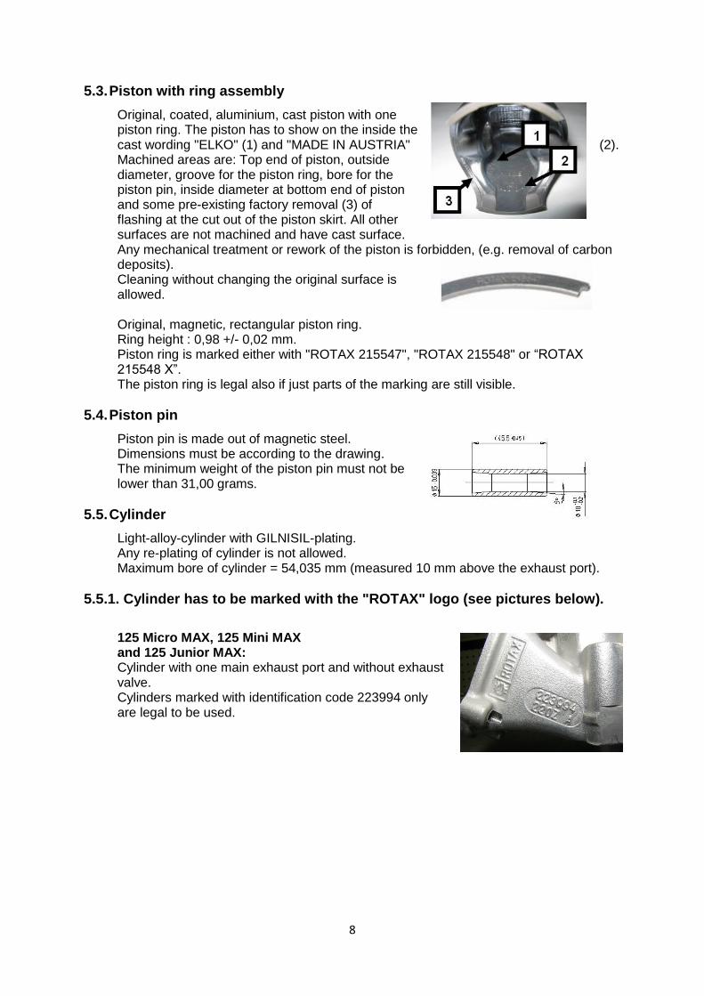
Cast identification code has to be "223389" or "223389 1" or "223389 2" or 223389 2/1" or “223389 2/2”. Casted wording "ROTAX" and/or "MADE IN AUSTRIA" must be shown. Height of combustion chamber insert has to be 28,80 mm +/- 0,2 mm (H). The profile of the combustion chamber insert has to be checked with a template (ROTAX 277390). The crack of light between the template and the profile of the combustion chamber insert must be the same over the whole profile.
8
5.3. Piston with ring assembly
Original, coated, aluminium, cast piston with one piston ring. The piston has to show on the inside the cast wording "ELKO" (1) and "MADE IN AUSTRIA" (2). Machined areas are: Top end of piston, outside diameter, groove for the piston ring, bore for the piston pin, inside diameter at bottom end of piston and some pre-existing factory removal (3) of flashing at the cut out of the piston skirt. All other surfaces are not machined and have cast surface. Any mechanical treatment or rework of the piston is forbidden, (e.g. removal of carbon deposits). Cleaning without changing the original surface is allowed. Original, magnetic, rectangular piston ring. Ring height : 0,98 +/- 0,02 mm. Piston ring is marked either with "ROTAX 215547", "ROTAX 215548" or “ROTAX 215548 X”. The piston ring is legal also if just parts of the marking are still visible.
5.4. Piston pin
Piston pin is made out of magnetic steel. Dimensions must be according to the drawing. The minimum weight of the piston pin must not be lower than 31,00 grams.
5.5. Cylinder
Light-alloy-cylinder with GILNISIL-plating. Any re-plating of cylinder is not allowed. Maximum bore of cylinder = 54,035 mm (measured 10 mm above the exhaust port).
5.5.1. Cylinder has to be marked with the "ROTAX" logo (see pictures below).
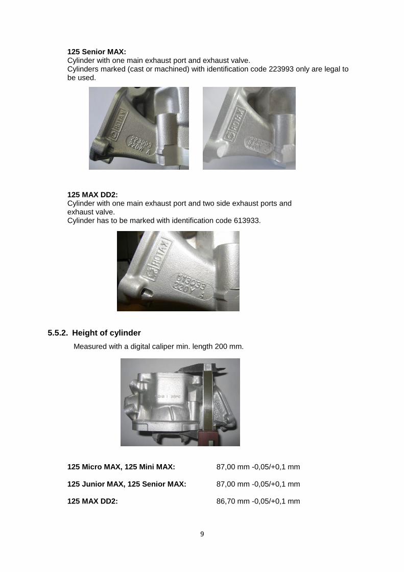
125 Micro MAX, 125 Mini MAX and 125 Junior MAX: Cylinder with one main exhaust port and without exhaust valve. Cylinders marked with identification code 223994 only are legal to be used.
9
125 Senior MAX: Cylinder with one main exhaust port and exhaust valve. Cylinders marked (cast or machined) with identification code 223993 only are legal to be used.
125 MAX DD2: Cylinder with one main exhaust port and two side exhaust ports and exhaust valve. Cylinder has to be marked with identification code 613933.
5.5.2. Height of cylinder
Measured with a digital caliper min. length 200 mm.
125 Micro MAX, 125 Mini MAX: 87,00 mm -0,05/+0,1 mm 125 Junior MAX, 125 Senior MAX: 87,00 mm -0,05/+0,1 mm 125 MAX DD2: 86,70 mm -0,05/+0,1 mm
10
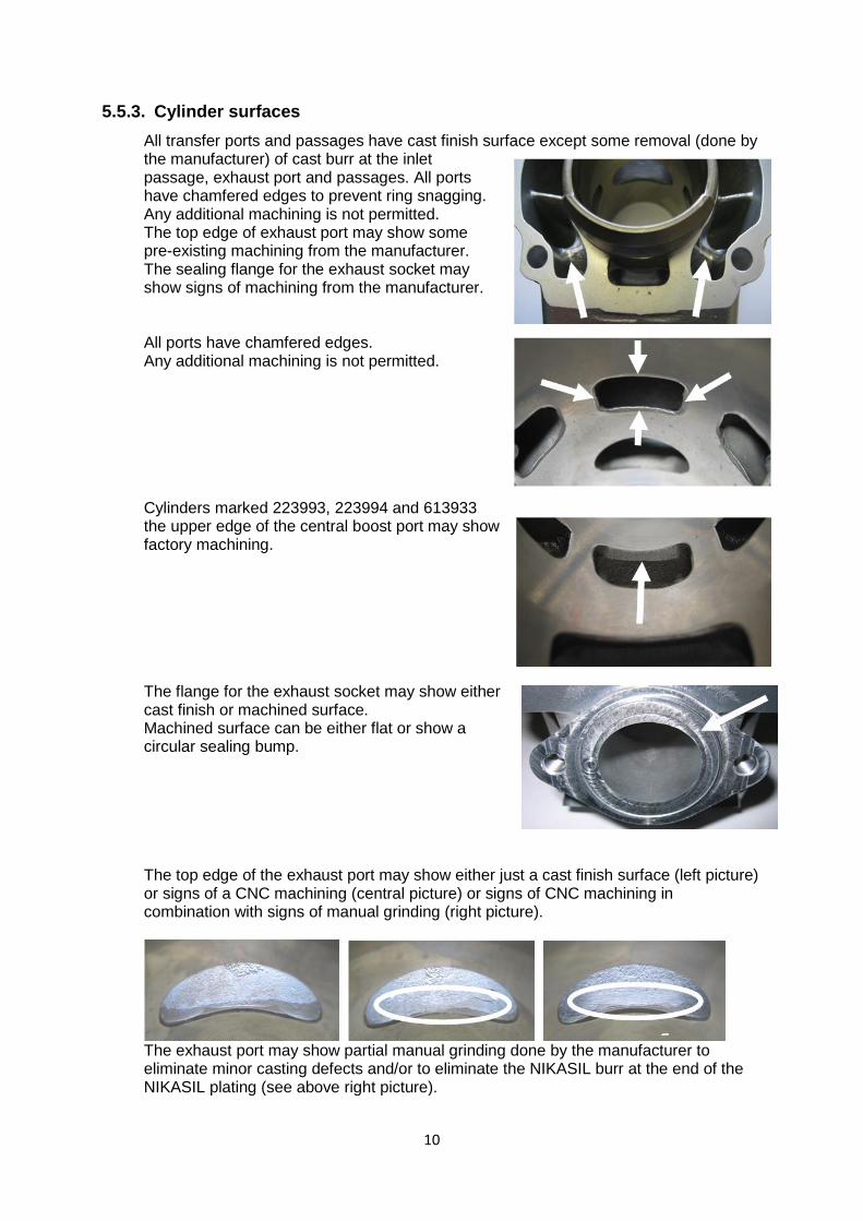
5.5.3. Cylinder surfaces
All transfer ports and passages have cast finish surface except some removal (done by the manufacturer) of cast burr at the inlet passage, exhaust port and passages. All ports have chamfered edges to prevent ring snagging. Any additional machining is not permitted. The top edge of exhaust port may show some pre-existing machining from the manufacturer. The sealing flange for the exhaust socket may show signs of machining from the manufacturer. All ports have chamfered edges. Any additional machining is not permitted. Cylinders marked 223993, 223994 and 613933 the upper edge of the central boost port may show factory machining. The flange for the exhaust socket may show either cast finish or machined surface. Machined surface can be either flat or show a circular sealing bump. The top edge of the exhaust port may show either just a cast finish surface (left picture) or signs of a CNC machining (central picture) or signs of CNC machining in combination with signs of manual grinding (right picture).
The exhaust port may show partial manual grinding done by the manufacturer to eliminate minor casting defects and/or to eliminate the NIKASIL burr at the end of the NIKASIL plating (see above right picture).
11
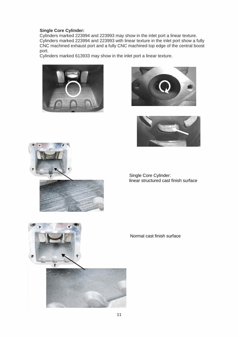
Single Core Cylinder: Cylinders marked 223994 and 223993 may show in the inlet port a linear texture. Cylinders marked 223994 and 223993 with linear texture in the inlet port show a fully CNC machined exhaust port and a fully CNC machined top edge of the central boost port. Cylinders marked 613933 may show in the inlet port a linear texture.
Normal cast finish surface
Single Core Cylinder: linear structured cast finish surface
12
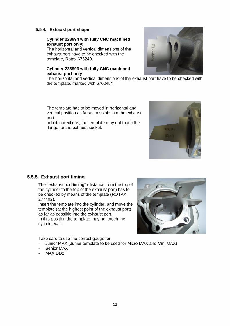
5.5.4. Exhaust port shape
Cylinder 223994 with fully CNC machined exhaust port only: The horizontal and vertical dimensions of the exhaust port have to be checked with the template, Rotax 676240.
Cylinder 223993 with fully CNC machined exhaust port only The horizontal and vertical dimensions of the exhaust port have to be checked with the template, marked with 676245*.
The template has to be moved in horizontal and vertical position as far as possible into the exhaust port. In both directions, the template may not touch the flange for the exhaust socket.
5.5.5. Exhaust port timing
The "exhaust port timing" (distance from the top of the cylinder to the top of the exhaust port) has to be checked by means of the template (ROTAX 277402). Insert the template into the cylinder, and move the template (at the highest point of the exhaust port) as far as possible into the exhaust port. In this position the template may not touch the cylinder wall. Take care to use the correct gauge for: - Junior MAX (Junior template to be used for Micro MAX and Mini MAX) - Senior MAX - MAX DD2
13
5.6.Inlet system
5.6.1. Reed valve assy
The reed valve assy. is equipped with 2 petal stops and 2 reeds, each having 3 petals. The thickness of the reeds is 0,6 mm +/- 0,10 mm.
5.6.2. Inlet manifold
Some factory flash removal may be present at the conjunction of the inside contour and the carburettor stop mounting face. This is a manual trimming operation consisting of a small corner break of less than 3 mm in width. No additional grinding or machining is permitted. 125 Micro MAX, 125 Mini MAX, 125 Junior MAX and 125 Senior MAX: Inlet manifold marked with the identification code “267915” and the name “ROTAX” or just “267916”. 125 MAX DD2: Inlet manifold marked with the identification code “267410” and the name “ROTAX” or just “267411”.
5.7. Crankshaft
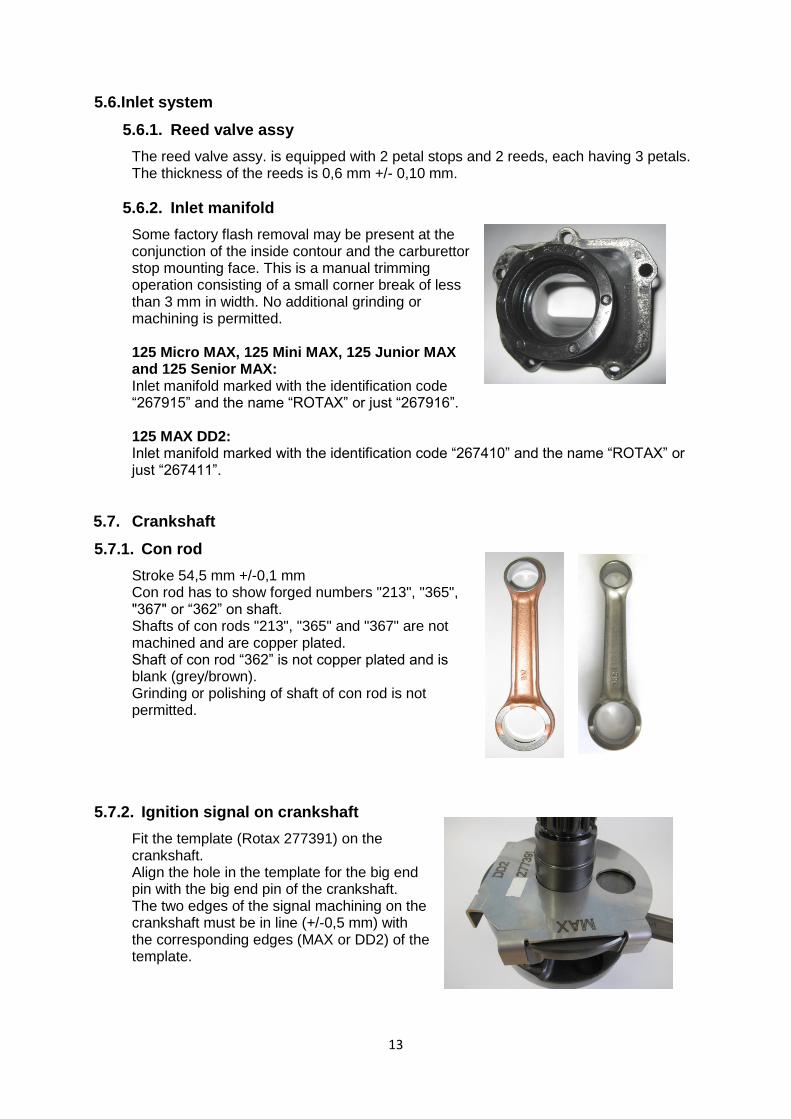
5.7.1. Con rod
Stroke 54,5 mm +/-0,1 mm Con rod has to show forged numbers "213", "365", "367" or “362” on shaft. Shafts of con rods "213", "365" and "367" are not machined and are copper plated. Shaft of con rod “362” is not copper plated and is blank (grey/brown). Grinding or polishing of shaft of con rod is not permitted.
5.7.2. Ignition signal on crankshaft
Fit the template (Rotax 277391) on the crankshaft. Align the hole in the template for the big end pin with the big end pin of the crankshaft. The two edges of the signal machining on the crankshaft must be in line (+/-0,5 mm) with the corresponding edges (MAX or DD2) of the template.
14
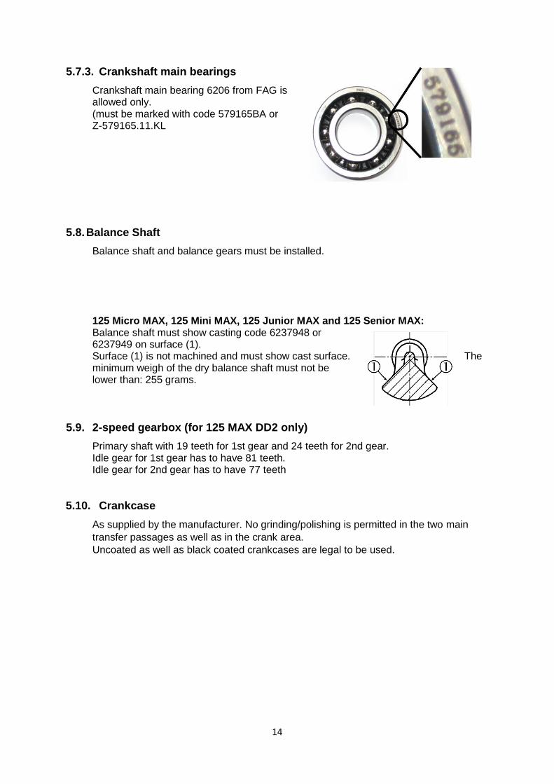
5.7.3. Crankshaft main bearings
Crankshaft main bearing 6206 from FAG is allowed only. (must be marked with code 579165BA or Z-579165.11.KL
5.8. Balance Shaft
Balance shaft and balance gears must be installed.
125 Micro MAX, 125 Mini MAX, 125 Junior MAX and 125 Senior MAX: Balance shaft must show casting code 6237948 or 6237949 on surface (1). Surface (1) is not machined and must show cast surface. The minimum weigh of the dry balance shaft must not be lower than: 255 grams.
5.9. 2-speed gearbox (for 125 MAX DD2 only)
Primary shaft with 19 teeth for 1st gear and 24 teeth for 2nd gear. Idle gear for 1st gear has to have 81 teeth. Idle gear for 2nd gear has to have 77 teeth
5.10. Crankcase
As supplied by the manufacturer. No grinding/polishing is permitted in the two main
transfer passages as well as in the crank area.
Uncoated as well as black coated crankcases are legal to be used.
15
6. Technical Specification outside the engine seal for Rotax MAX kart engines It is the responsibility of the competitor to check his equipment (all components outside the engine seal as mentioned below), to assure that his equipment is conforming to the technical specification below!
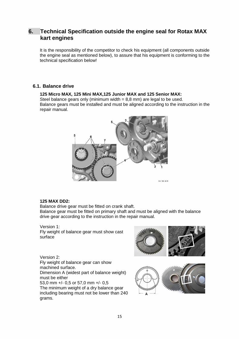
6.1. Balance drive
125 Micro MAX, 125 Mini MAX,125 Junior MAX and 125 Senior MAX: Steel balance gears only (minimum width = 8,8 mm) are legal to be used. Balance gears must be installed and must be aligned according to the instruction in the repair manual. 125 MAX DD2: Balance drive gear must be fitted on crank shaft. Balance gear must be fitted on primary shaft and must be aligned with the balance drive gear according to the instruction in the repair manual. Version 1: Fly weight of balance gear must show cast surface
Version 2: Fly weight of balance gear can show machined surface. Dimension A (widest part of balance weight) must be either 53,0 mm +/- 0,5 or 57,0 mm +/- 0,5 The minimum weight of a dry balance gear including bearing must not be lower than 240 grams.

16
6.2. Centrifugal clutch
6.2.1. Components
125 Micro MAX, 125 Mini MAX, 125 Junior MAX and 125 Senior MAX: Engagement speed of centrifugal clutch at maximum 4.000 rpm (the kart without driver must start to move). Two versions of clutch (item 1, with and without holes) are legal to be used. Both versions are marked with the wording “ROTAX”. O-ring (item 2) must be fitted and must assure an appropriate sealing between the clutch drum and the needle/plain bearing. Two versions of clutch drum (item 3) are legal to be used. Both versions are marked with the wording “ROTAX”. Signs of emission of grease from the needle/plain bearing into the clutch drum may not exceed the picture beside. Contact area between clutch and clutch drum has to be dry at any time – no lubrication allowed. 125 MAX DD2: Engagement speed of centrifugal clutch at maximum 4.000 rpm (the kart without driver must start to move). Both versions of clutch (item 6, with and without holes) are legal to be used. O-ring (item 11) must be fitted.

17
6.2.2. Clutch dimensions
Thickness of clutch shoe (A): All MAX Engines Minimum = 24,10 mm Measurement must be done at the 3 open ends of the clutch, 5 - 10 mm from the machined groove (all clutch shoes must be completely closed at measurement - no gap). Height of clutch (B): 125 Micro MAX, 125 Mini MAX : Minimum = 11,45 mm 125 Junior MAX and 125 Senior MAX: Minimum = 11,45 mm 125 MAX DD2: Minimum = 14,45 mm Clutch drum Outer diameter (C): Minimum = 89,50 mm Diameter must be measured with a sliding calliper just beside the radius from the shoulder (not at the open end of the clutch drum). Clutch drum Inner diameter (D): Maximum = 84,90 mm Diameter must be measured with a sliding calliper. The measurement must be done in the middle of the clutch drum (in the contact area between clutch and clutch drum).
Clutch drum Height (E) with sprocket/primary gear 125 Micro MAX, 125 Mini MAX: Minimum = 33,90 mm 125 Junior MAX, 125 Senior MAX: Minimum = 33,90 mm 125 MAX DD2: Minimum = 39,50 mm
18
6.3. Primary drive (125 MAX DD2):
Original primary drive gears (4+5) of following gear ratio options must be used only. Following combinations are legal to be used. Drive gear Driven gear 32 65 33 64 34 63 35 62 36 61 37 60 38 59 A specific primary gear ratio may be determined for each race event by a “Bulletin”.
6.4. Gear shifting (125 MAX DD2)
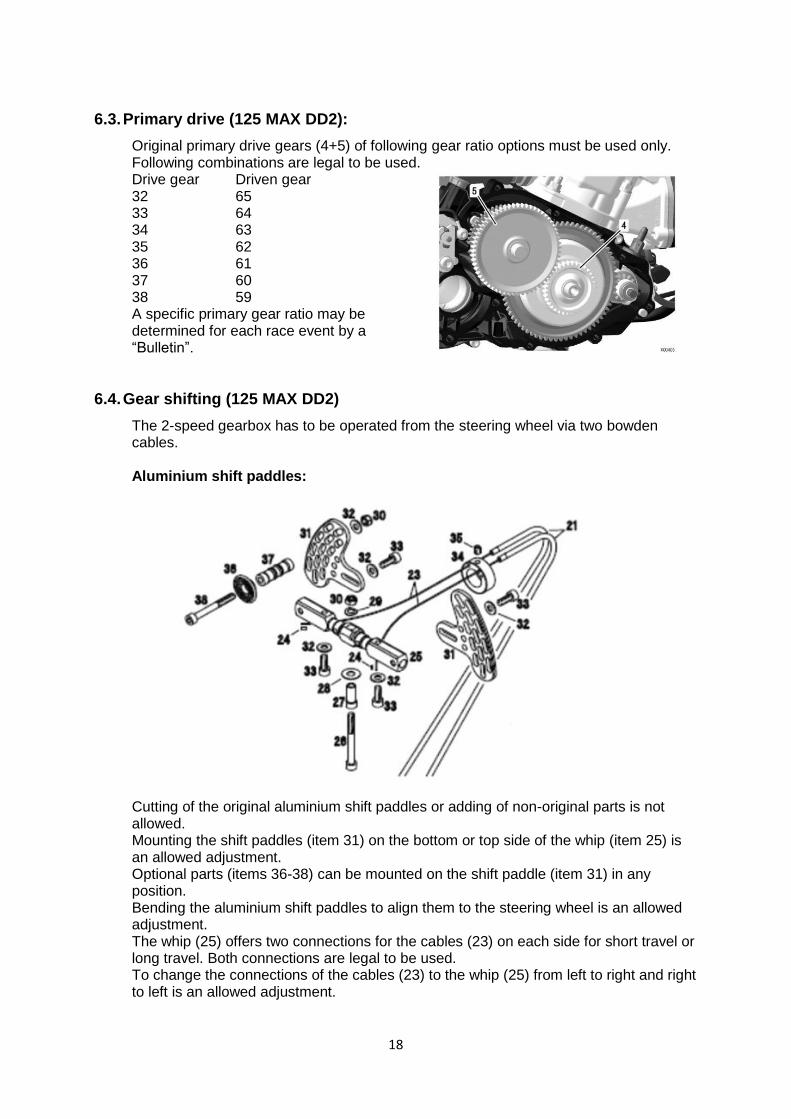
The 2-speed gearbox has to be operated from the steering wheel via two bowden cables. Aluminium shift paddles:
Cutting of the original aluminium shift paddles or adding of non-original parts is not allowed. Mounting the shift paddles (item 31) on the bottom or top side of the whip (item 25) is an allowed adjustment. Optional parts (items 36-38) can be mounted on the shift paddle (item 31) in any position. Bending the aluminium shift paddles to align them to the steering wheel is an allowed adjustment. The whip (25) offers two connections for the cables (23) on each side for short travel or long travel. Both connections are legal to be used. To change the connections of the cables (23) to the whip (25) from left to right and right to left is an allowed adjustment.
19
6.5. Combination of ignition system, carburettor and exhaust system
The combination of components is limited to following specification per engine type.
Component \ MAX Engine Micro
Mini
Junior Senior DD2
Ignition system Dell'orto ✓ ✓ ✓ ✓
Exhaust valve, electronic timed ✓ ✓
Carburettor XS ✓ ✓ ✓ ✓
Exhaust system, evo ✓ ✓ ✓ ✓
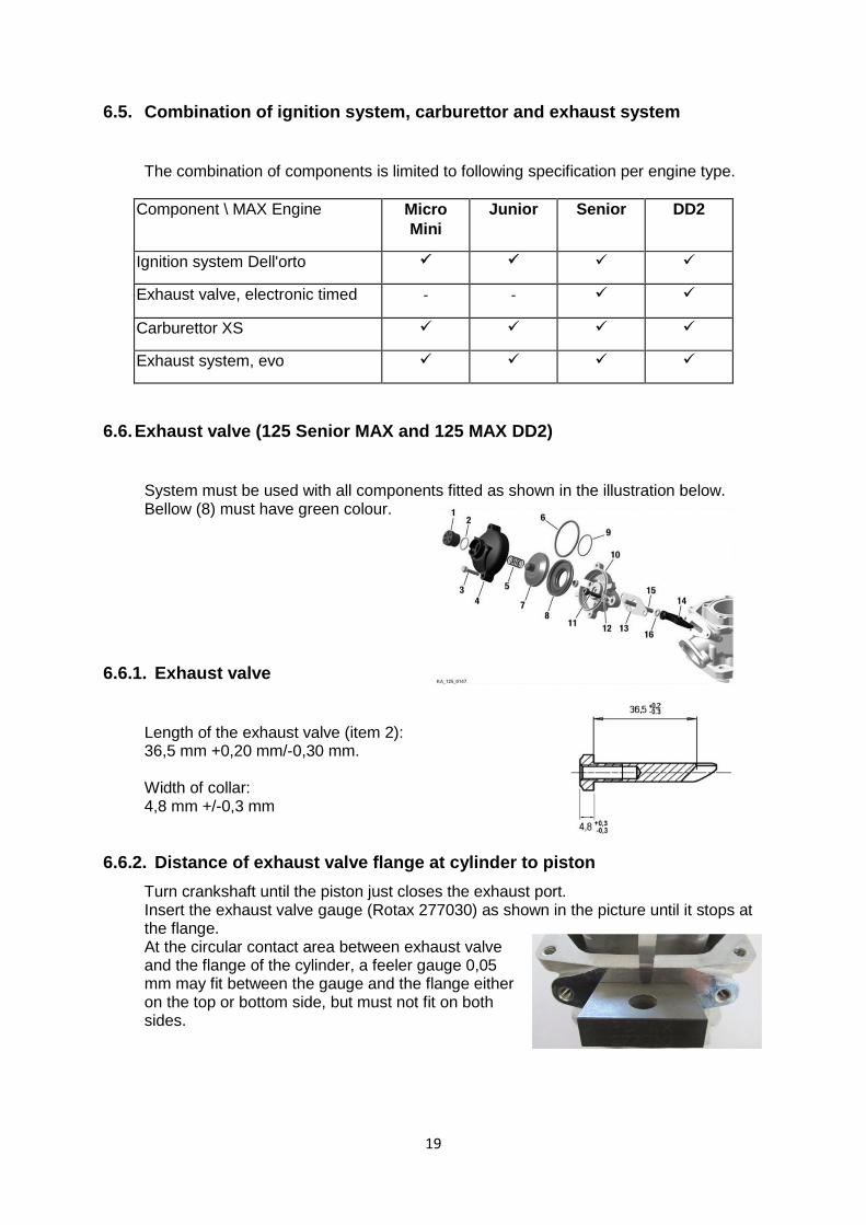
6.6. Exhaust valve (125 Senior MAX and 125 MAX DD2)
System must be used with all components fitted as shown in the illustration below. Bellow (8) must have green colour.
6.6.1. Exhaust valve
Length of the exhaust valve (item 2): 36,5 mm +0,20 mm/-0,30 mm. Width of collar: 4,8 mm +/-0,3 mm
6.6.2. Distance of exhaust valve flange at cylinder to piston
Turn crankshaft until the piston just closes the exhaust port. Insert the exhaust valve gauge (Rotax 277030) as shown in the picture until it stops at the flange. At the circular contact area between exhaust valve and the flange of the cylinder, a feeler gauge 0,05 mm may fit between the gauge and the flange either on the top or bottom side, but must not fit on both sides.
20
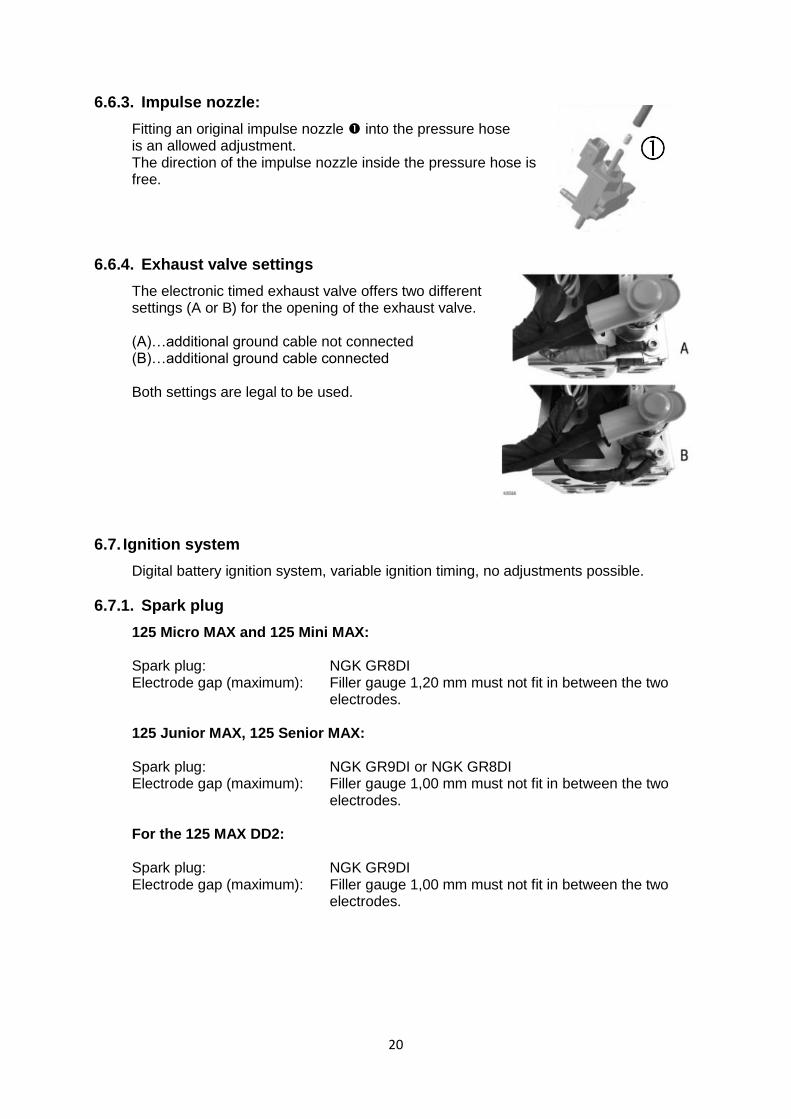
6.6.3. Impulse nozzle:
Fitting an original impulse nozzle into the pressure hose is an allowed adjustment. The direction of the impulse nozzle inside the pressure hose is free.
6.6.4. Exhaust valve settings
The electronic timed exhaust valve offers two different settings (A or B) for the opening of the exhaust valve. (A)…additional ground cable not connected (B)…additional ground cable connected Both settings are legal to be used.
6.7. Ignition system
Digital battery ignition system, variable ignition timing, no adjustments possible.
6.7.1. Spark plug
125 Micro MAX and 125 Mini MAX: Spark plug: NGK GR8DI Electrode gap (maximum): Filler gauge 1,20 mm must not fit in between the two
electrodes. 125 Junior MAX, 125 Senior MAX: Spark plug: NGK GR9DI or NGK GR8DI Electrode gap (maximum): Filler gauge 1,00 mm must not fit in between the two
electrodes. For the 125 MAX DD2: Spark plug: NGK GR9DI Electrode gap (maximum): Filler gauge 1,00 mm must not fit in between the two
electrodes.
21
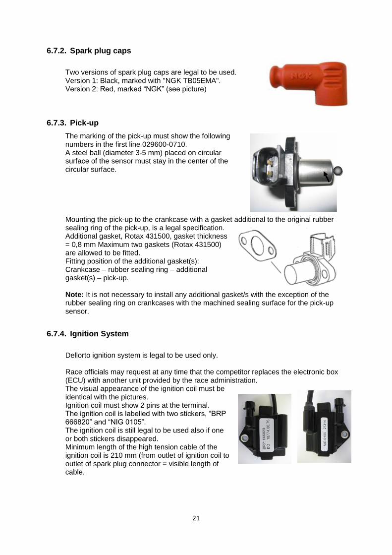
6.7.2. Spark plug caps
Two versions of spark plug caps are legal to be used. Version 1: Black, marked with "NGK TB05EMA". Version 2: Red, marked “NGK” (see picture)
6.7.3. Pick-up
The marking of the pick-up must show the following numbers in the first line 029600-0710. A steel ball (diameter 3-5 mm) placed on circular surface of the sensor must stay in the center of the circular surface. Mounting the pick-up to the crankcase with a gasket additional to the original rubber sealing ring of the pick-up, is a legal specification. Additional gasket, Rotax 431500, gasket thickness = 0,8 mm Maximum two gaskets (Rotax 431500) are allowed to be fitted. Fitting position of the additional gasket(s): Crankcase – rubber sealing ring – additional gasket(s) – pick-up. Note: It is not necessary to install any additional gasket/s with the exception of the rubber sealing ring on crankcases with the machined sealing surface for the pick-up sensor.
6.7.4. Ignition System
Dellorto ignition system is legal to be used only. Race officials may request at any time that the competitor replaces the electronic box (ECU) with another unit provided by the race administration. The visual appearance of the ignition coil must be identical with the pictures. Ignition coil must show 2 pins at the terminal. The ignition coil is labelled with two stickers, “BRP 666820” and “NIG 0105”. The ignition coil is still legal to be used also if one or both stickers disappeared. Minimum length of the high tension cable of the ignition coil is 210 mm (from outlet of ignition coil to outlet of spark plug connector = visible length of cable.

22
Ignition coil (same for all engines) with separate electronic box (ECU, specific for every engine). Ignition coil and ECU (and magnet valve, for 125 Senior MAX and 125 MAX DD2 only) must be fitted with all components according to the illustrations below. Two different mounting versions (left illustration and right illustration) are legal. 125 Micro MAX, 125 Mini MAX, 125 Junior MAX and 125 Senior MAX: In case the mounting bracket (125 Micro MAX, 125 Mini Max, 125 Junior MAX and 125 Senior MAX only) is in conflict with a chassis component, the additions of 2 spacers, one per mounting hole, with a maximum thickness of 20 mm between the mounting bracket and the gearbox cover is allowed. Removing the black coating of the gearbox cover (125 Micro MAX, 125 Mini MAX, 125 Junior MAX and 125 Senior MAX) in specific areas defined by Rotax (for mass connection between cable harness and engine) is a legal modification.
125 MAX DD2: At the mounting versions as shown in the left illustrations, the ground cable of the cable harness must be connected to the lower rubber buffer of the support plate
23
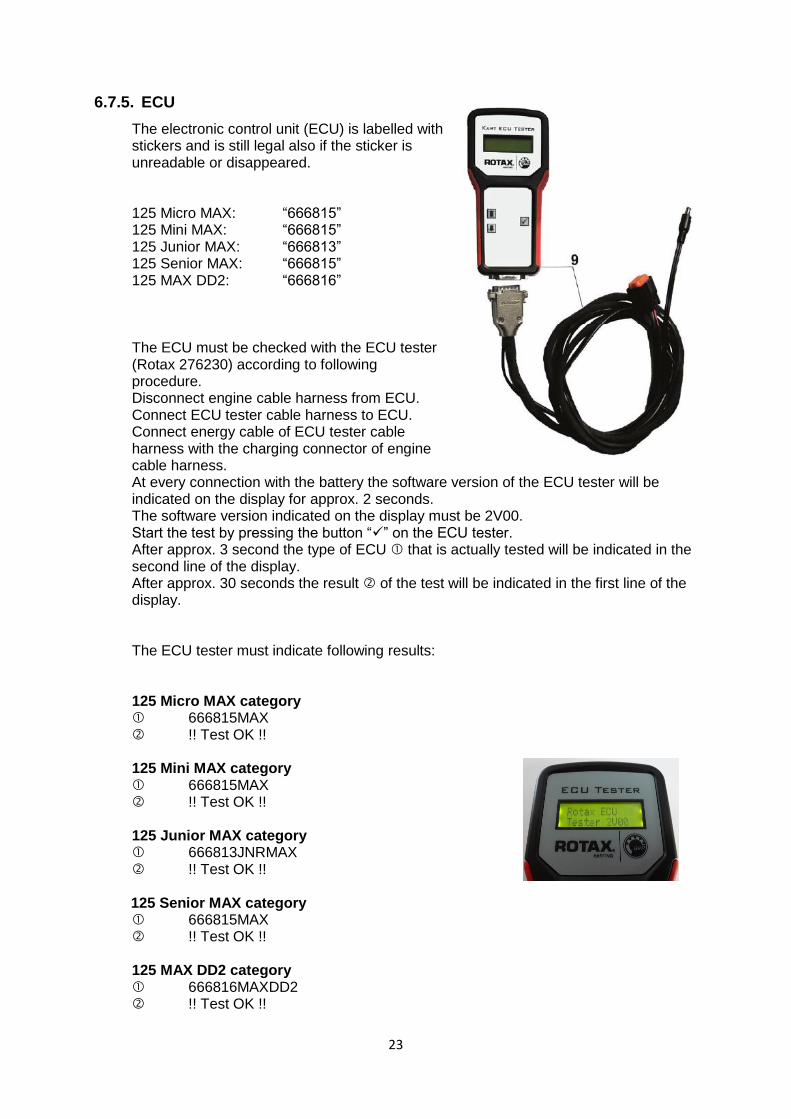
6.7.5. ECU
The electronic control unit (ECU) is labelled with stickers and is still legal also if the sticker is unreadable or disappeared. 125 Micro MAX: “666815” 125 Mini MAX: “666815” 125 Junior MAX: “666813” 125 Senior MAX: “666815” 125 MAX DD2: “666816”
The ECU must be checked with the ECU tester (Rotax 276230) according to following procedure. Disconnect engine cable harness from ECU. Connect ECU tester cable harness to ECU. Connect energy cable of ECU tester cable harness with the charging connector of engine cable harness. At every connection with the battery the software version of the ECU tester will be indicated on the display for approx. 2 seconds. The software version indicated on the display must be 2V00. Start the test by pressing the button “✓” on the ECU tester. After approx. 3 second the type of ECU that is actually tested will be indicated in the second line of the display. After approx. 30 seconds the result of the test will be indicated in the first line of the display.
The ECU tester must indicate following results: 125 Micro MAX category 666815MAX !! Test OK !! 125 Mini MAX category 666815MAX !! Test OK !! 125 Junior MAX category 666813JNRMAX !! Test OK !!
125 Senior MAX category
666815MAX !! Test OK !! 125 MAX DD2 category 666816MAXDD2 !! Test OK !!
24
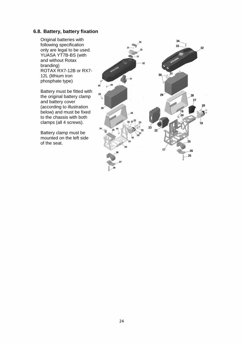
6.8. Battery, battery fixation
Original batteries with following specification only are legal to be used. YUASA YT7B-BS (with and without Rotax branding) ROTAX RX7-12B or RX7-12L (lithium iron phosphate type) Battery must be fitted with the original battery clamp and battery cover (according to illustration below) and must be fixed to the chassis with both clamps (all 4 screws). Battery clamp must be mounted on the left side of the seat.

25
6.9. Intake silencer
125 Micro MAX , 125 Mini MAX, 125 Junior MAX and 125 Senior MAX
Intake silencer with integrated, washable air filter must be used with all parts as shown at the illustration and has to be mounted on the support bracket with two screws (in dry and wet condition). Intake silencer tube (pos 2) and carburettor socket (pos 6) are marked with the wording "ROTAX". Intake silencer case bottom is marked on the inside with “225015”. Intake silencer case, top is marked on the inside with “225025”. Three versions of original air filters (pos.4) are legal to be used. Single layer air filter (black), double layer air filter (green/orange), double layer air filter (green/dark green) marked “Twin Air”. Depending on the degree of oil-lubrication colours may alter slightly or the surface becomes stained (see examples). Air filter (pos 4) must be installed as shown in the illustration between the two holders (pos 3) and must cover the complete area of the intake silencer case bottom (pos1). During wet condition, it is not allowed to attach anything to the air box to protect the air inlet from water spray.
Pos. 4, legal air filter executions
26
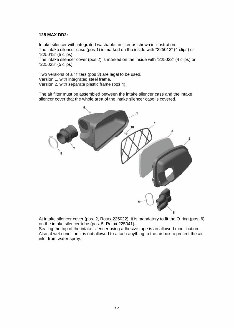
125 MAX DD2: Intake silencer with integrated washable air filter as shown in illustration. The intake silencer case (pos 1) is marked on the inside with “225012” (4 clips) or “225013” (5 clips). The intake silencer cover (pos 2) is marked on the inside with “225022” (4 clips) or “225023” (5 clips). Two versions of air filters (pos 3) are legal to be used. Version 1, with integrated steel frame. Version 2, with separate plastic frame (pos 4). The air filter must be assembled between the intake silencer case and the intake silencer cover that the whole area of the intake silencer case is covered.
At intake silencer cover (pos. 2, Rotax 225022), it is mandatory to fit the O-ring (pos. 6) on the intake silencer tube (pos. 5, Rotax 225041). Sealing the top of the intake silencer using adhesive tape is an allowed modification. Also at wet condition it is not allowed to attach anything to the air box to protect the air inlet from water spray.
27
6.10. Carburettor
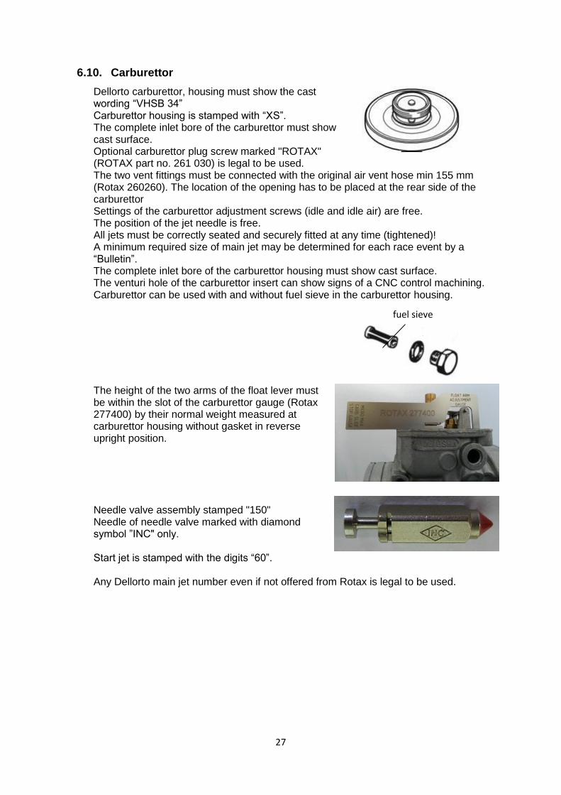
Dellorto carburettor, housing must show the cast wording “VHSB 34” Carburettor housing is stamped with “XS”. The complete inlet bore of the carburettor must show cast surface. Optional carburettor plug screw marked "ROTAX" (ROTAX part no. 261 030) is legal to be used. The two vent fittings must be connected with the original air vent hose min 155 mm (Rotax 260260). The location of the opening has to be placed at the rear side of the carburettor Settings of the carburettor adjustment screws (idle and idle air) are free. The position of the jet needle is free. All jets must be correctly seated and securely fitted at any time (tightened)! A minimum required size of main jet may be determined for each race event by a “Bulletin”. The complete inlet bore of the carburettor housing must show cast surface. The venturi hole of the carburettor insert can show signs of a CNC control machining. Carburettor can be used with and without fuel sieve in the carburettor housing. The height of the two arms of the float lever must be within the slot of the carburettor gauge (Rotax 277400) by their normal weight measured at carburettor housing without gasket in reverse upright position. Needle valve assembly stamped "150" Needle of needle valve marked with diamond symbol ”INC" only. Start jet is stamped with the digits “60”. Any Dellorto main jet number even if not offered from Rotax is legal to be used.
fuel sieve
28
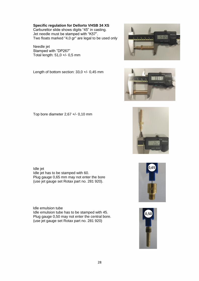
Specific regulation for Dellorto VHSB 34 XS Carburettor slide shows digits “45” in casting. Jet needle must be stamped with “K57”. Two floats marked "4,0 gr" are legal to be used only Needle jet Stamped with ”DP267” Total length: 51,0 +/- 0,5 mm Length of bottom section: 33,0 +/- 0,45 mm Top bore diameter 2,67 +/- 0,10 mm
Idle jet Idle jet has to be stamped with 60. Plug gauge 0,65 mm may not enter the bore (use jet gauge set Rotax part no. 281 920).
Idle emulsion tube Idle emulsion tube has to be stamped with 45. Plug gauge 0,50 may not enter the central bore. (use jet gauge set Rotax part no. 281 920)
29
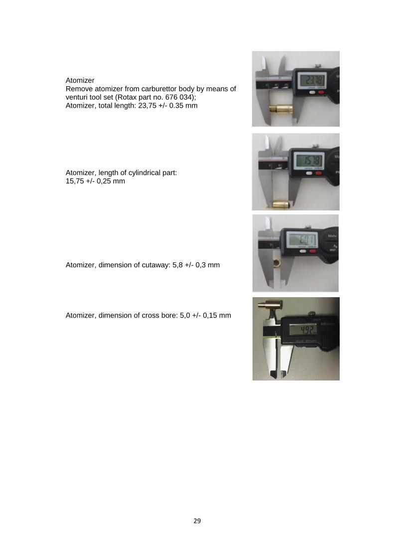
Atomizer Remove atomizer from carburettor body by means of venturi tool set (Rotax part no. 676 034); Atomizer, total length: 23,75 +/- 0.35 mm Atomizer, length of cylindrical part: 15,75 +/- 0,25 mm Atomizer, dimension of cutaway: 5,8 +/- 0,3 mm Atomizer, dimension of cross bore: 5,0 +/- 0,15 mm
30
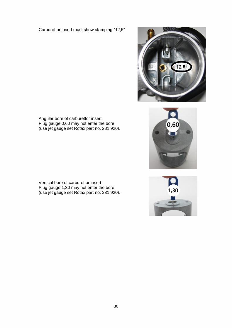
Carburettor insert must show stamping “12,5” Angular bore of carburettor insert Plug gauge 0,60 may not enter the bore (use jet gauge set Rotax part no. 281 920). Vertical bore of carburettor insert Plug gauge 1,30 may not enter the bore (use jet gauge set Rotax part no. 281 920).
31
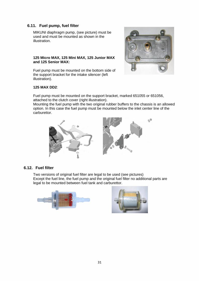
6.11. Fuel pump, fuel filter
MIKUNI diaphragm pump, (see picture) must be used and must be mounted as shown in the illustration. 125 Micro MAX, 125 Mini MAX, 125 Junior MAX and 125 Senior MAX: Fuel pump must be mounted on the bottom side of the support bracket for the intake silencer (left illustration). 125 MAX DD2: Fuel pump must be mounted on the support bracket, marked 651055 or 651056, attached to the clutch cover (right illustration). Mounting the fuel pump with the two original rubber buffers to the chassis is an allowed option. In this case the fuel pump must be mounted below the inlet center line of the carburettor.
6.12. Fuel filter
Two versions of original fuel filter are legal to be used (see pictures) Except the fuel line, the fuel pump and the original fuel filter no additional parts are legal to be mounted between fuel tank and carburettor.
32
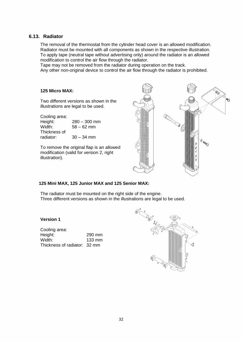
6.13. Radiator
The removal of the thermostat from the cylinder head cover is an allowed modification. Radiator must be mounted with all components as shown in the respective illustration. To apply tape (neutral tape without advertising only) around the radiator is an allowed modification to control the air flow through the radiator. Tape may not be removed from the radiator during operation on the track. Any other non-original device to control the air flow through the radiator is prohibited. 125 Micro MAX: Two different versions as shown in the illustrations are legal to be used. Cooling area: Height: 280 – 300 mm Width: 58 – 62 mm Thickness of radiator: 30 – 34 mm To remove the original flap is an allowed modification (valid for version 2, right illustration).
125 Mini MAX, 125 Junior MAX and 125 Senior MAX: The radiator must be mounted on the right side of the engine. Three different versions as shown in the illustrations are legal to be used. Version 1 Cooling area: Height: 290 mm Width: 133 mm Thickness of radiator: 32 mm
33
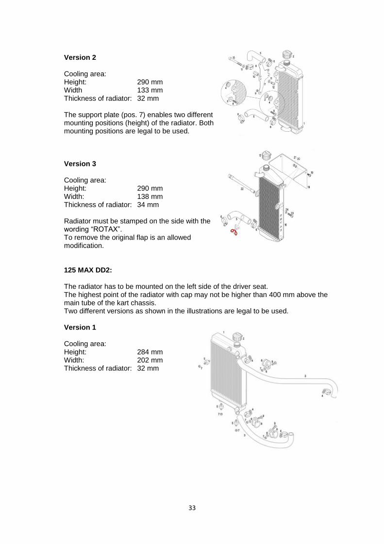
Version 2 Cooling area: Height: 290 mm Width 133 mm Thickness of radiator: 32 mm The support plate (pos. 7) enables two different mounting positions (height) of the radiator. Both mounting positions are legal to be used. Version 3 Cooling area: Height: 290 mm Width: 138 mm Thickness of radiator: 34 mm Radiator must be stamped on the side with the wording “ROTAX”. To remove the original flap is an allowed modification. 125 MAX DD2: The radiator has to be mounted on the left side of the driver seat. The highest point of the radiator with cap may not be higher than 400 mm above the main tube of the kart chassis. Two different versions as shown in the illustrations are legal to be used. Version 1 Cooling area: Height: 284 mm Width: 202 mm Thickness of radiator: 32 mm
34
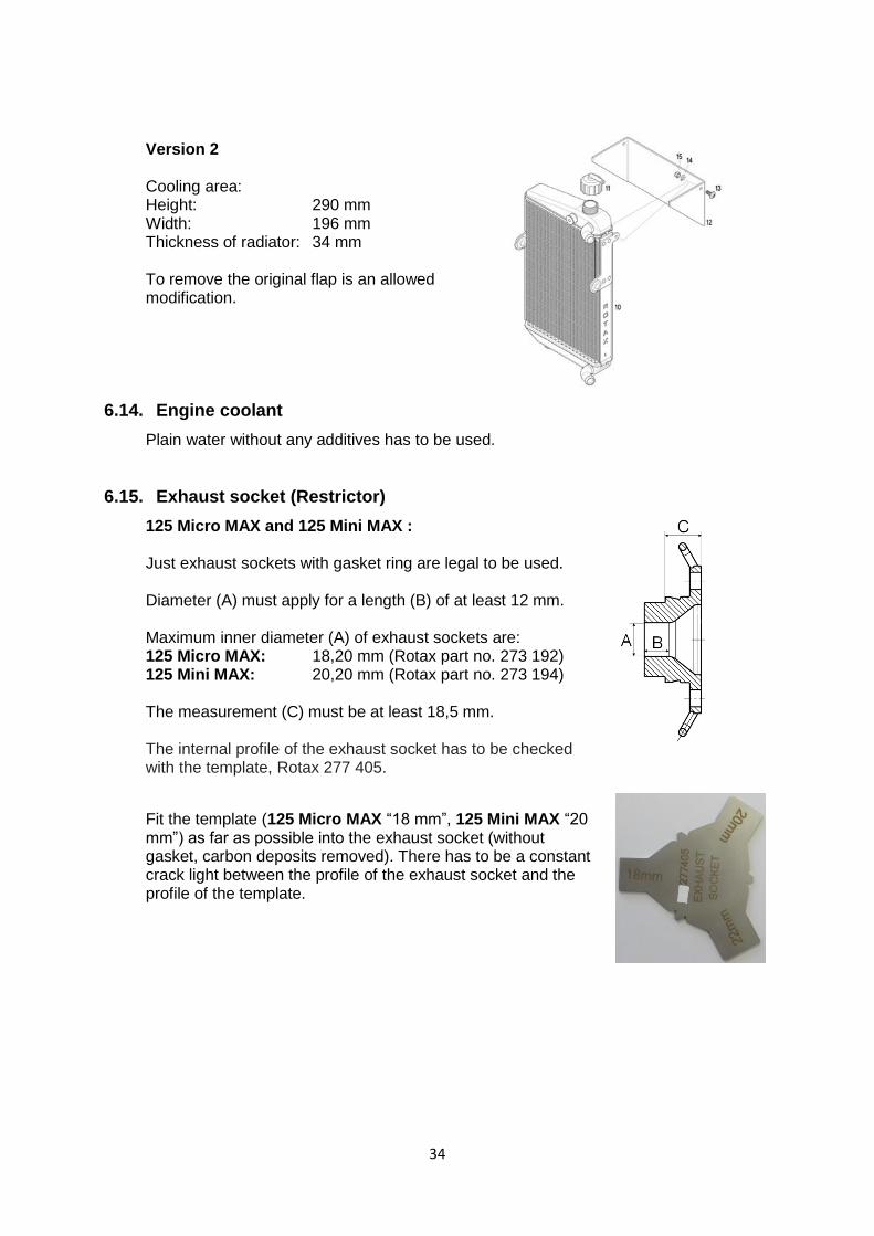
Version 2 Cooling area: Height: 290 mm Width: 196 mm Thickness of radiator: 34 mm To remove the original flap is an allowed modification.
6.14. Engine coolant
Plain water without any additives has to be used.
6.15. Exhaust socket (Restrictor)
125 Micro MAX and 125 Mini MAX : Just exhaust sockets with gasket ring are legal to be used. Diameter (A) must apply for a length (B) of at least 12 mm. Maximum inner diameter (A) of exhaust sockets are: 125 Micro MAX: 18,20 mm (Rotax part no. 273 192) 125 Mini MAX: 20,20 mm (Rotax part no. 273 194) The measurement (C) must be at least 18,5 mm. The internal profile of the exhaust socket has to be checked with the template, Rotax 277 405.
Fit the template (125 Micro MAX “18 mm”, 125 Mini MAX “20 mm”) as far as possible into the exhaust socket (without gasket, carbon deposits removed). There has to be a constant crack light between the profile of the exhaust socket and the profile of the template.
35
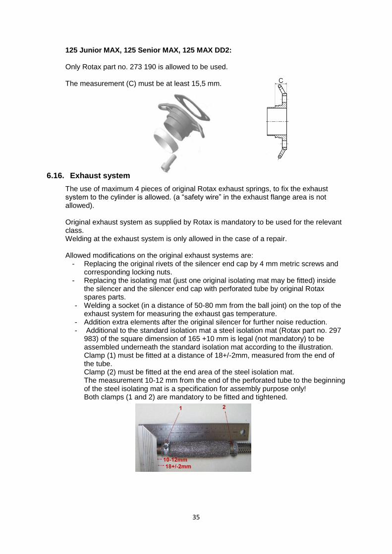
125 Junior MAX, 125 Senior MAX, 125 MAX DD2: Only Rotax part no. 273 190 is allowed to be used. The measurement (C) must be at least 15,5 mm.
6.16. Exhaust system
The use of maximum 4 pieces of original Rotax exhaust springs, to fix the exhaust system to the cylinder is allowed. (a “safety wire” in the exhaust flange area is not allowed). Original exhaust system as supplied by Rotax is mandatory to be used for the relevant class. Welding at the exhaust system is only allowed in the case of a repair. Allowed modifications on the original exhaust systems are:
- Replacing the original rivets of the silencer end cap by 4 mm metric screws and corresponding locking nuts.
- Replacing the isolating mat (just one original isolating mat may be fitted) inside the silencer and the silencer end cap with perforated tube by original Rotax spares parts.
- Welding a socket (in a distance of 50-80 mm from the ball joint) on the top of the exhaust system for measuring the exhaust gas temperature.
- Addition extra elements after the original silencer for further noise reduction. - Additional to the standard isolation mat a steel isolation mat (Rotax part no. 297
983) of the square dimension of 165 +10 mm is legal (not mandatory) to be assembled underneath the standard isolation mat according to the illustration. Clamp (1) must be fitted at a distance of 18+/-2mm, measured from the end of the tube. Clamp (2) must be fitted at the end area of the steel isolation mat. The measurement 10-12 mm from the end of the perforated tube to the beginning of the steel isolating mat is a specification for assembly purpose only! Both clamps (1 and 2) are mandatory to be fitted and tightened.
36
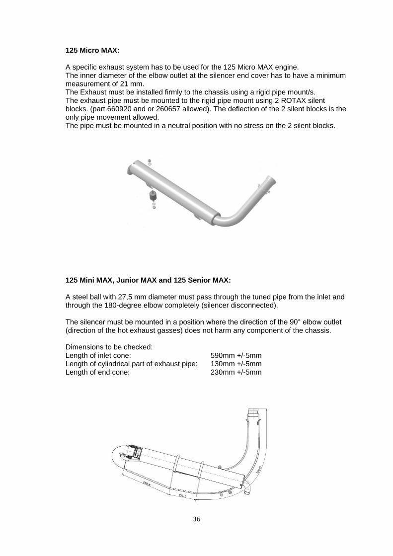
125 Micro MAX: A specific exhaust system has to be used for the 125 Micro MAX engine. The inner diameter of the elbow outlet at the silencer end cover has to have a minimum measurement of 21 mm. The Exhaust must be installed firmly to the chassis using a rigid pipe mount/s. The exhaust pipe must be mounted to the rigid pipe mount using 2 ROTAX silent blocks. (part 660920 and or 260657 allowed). The deflection of the 2 silent blocks is the only pipe movement allowed. The pipe must be mounted in a neutral position with no stress on the 2 silent blocks.
125 Mini MAX, Junior MAX and 125 Senior MAX: A steel ball with 27,5 mm diameter must pass through the tuned pipe from the inlet and through the 180-degree elbow completely (silencer disconnected). The silencer must be mounted in a position where the direction of the 90° elbow outlet (direction of the hot exhaust gasses) does not harm any component of the chassis. Dimensions to be checked: Length of inlet cone: 590mm +/-5mm Length of cylindrical part of exhaust pipe: 130mm +/-5mm Length of end cone: 230mm +/-5mm
37
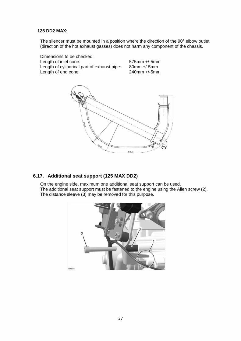
125 DD2 MAX: The silencer must be mounted in a position where the direction of the 90° elbow outlet (direction of the hot exhaust gasses) does not harm any component of the chassis. Dimensions to be checked: Length of inlet cone: 575mm +/-5mm Length of cylindrical part of exhaust pipe: 80mm +/-5mm Length of end cone: 240mm +/-5mm
6.17. Additional seat support (125 MAX DD2)
On the engine side, maximum one additional seat support can be used. The additional seat support must be fastened to the engine using the Allen screw (2). The distance sleeve (3) may be removed for this purpose.