cee 6100 / css 6600: remote sensing fundamentalsw.d. philpot, cornell univ. fall 2010radiation,...
TRANSCRIPT

CEE 6100 / CSS 6600: Remote Sensing Fundamentals W.D. Philpot, Cornell Univ. Fall 2010 Radiation, Radiometry and Blackbodies 1
The EM spectrum and associated detectors
0.1 µ
Ultraviolet
Multispectral scanners
Infrared film &silicon detectors
Ordinaryfilm
Infrared instruments THz
X-rays andgamma rays
VisibleHuman eye
Film & silicon
NearIR
(NIR)IR film
&silicon
Short-waveIR
(SWIR)HgCdTeInGaAs
Mid-wave(MIR)HgCdTeInAsSb
ThermalIR
(TIR)HgCdTe
PbS
0.4 µ 1 µ0.7 µ 3 µ 10 µ 30 µ
Infrared
0.4 µ 0.5 µ 0.6 µ 0.7 µ
IRUV Blue Green Red

CEE 6100 / CSS 6600: Remote Sensing Fundamentals W.D. Philpot, Cornell Univ. Fall 2010 Radiation, Radiometry and Blackbodies 2
EM radiation in the microwave
1mm 10cm
passive microwave systems
active systems (radar)
1cm
Ka X C S LK KuUHF
PBand designations:
1m
CEE 6100 / CSS 6600: Remote Sensing Fundamentals W.D. Philpot, Cornell Univ. Fall 2010 Radiation, Radiometry and Blackbodies 3
Radiative Transfer Concepts (Phenomenological Optics)
• Angular measures• plane angles• solid angles
• Radiative terms• Power (Flux)• Radiance• Irradiance
• Blackbody radiation• Reflectance• Attenuation (absorption & scattering)• Transmission
CEE 6100 / CSS 6600: Remote Sensing Fundamentals W.D. Philpot, Cornell Univ. Fall 2010 Radiation, Radiometry and Blackbodies 4
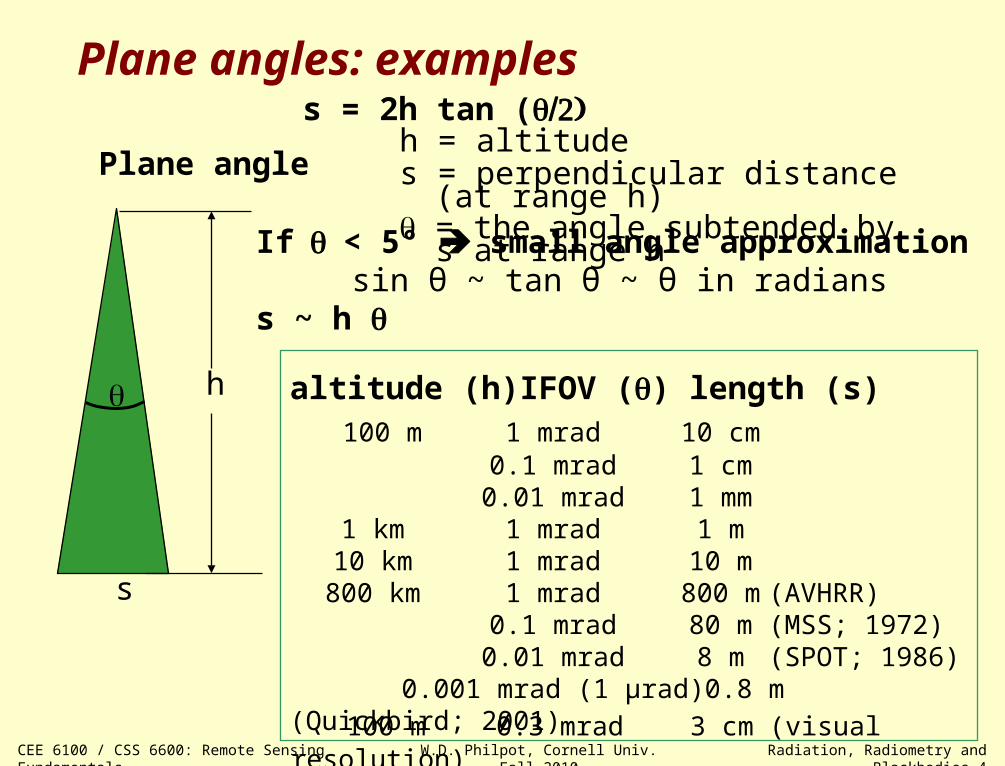
Plane angles: examples
Plane angleh = altitudes = perpendicular distance (at range h) = the angle subtended by s at range h
altitude (h) IFOV () length (s) 100 m 1 mrad 10 cm
0.1 mrad 1 cm0.01 mrad 1 mm
1 km 1 mrad 1 m10 km 1 mrad 10 m
800 km 1 mrad 800 m (AVHRR)0.1 mrad 80 m (MSS; 1972)
0.01 mrad 8 m (SPOT; 1986)0.001 mrad (1 µrad) 0.8 m (Quickbird; 2001)
If< 5° small angle approximationsin θ ~ tan θ ~ θ in radians
s ~ h
s = 2h tan (
h
s
100 m 0.3 mrad 3 cm (visual resolution)
CEE 6100 / CSS 6600: Remote Sensing Fundamentals W.D. Philpot, Cornell Univ. Fall 2010 Radiation, Radiometry and Blackbodies 5
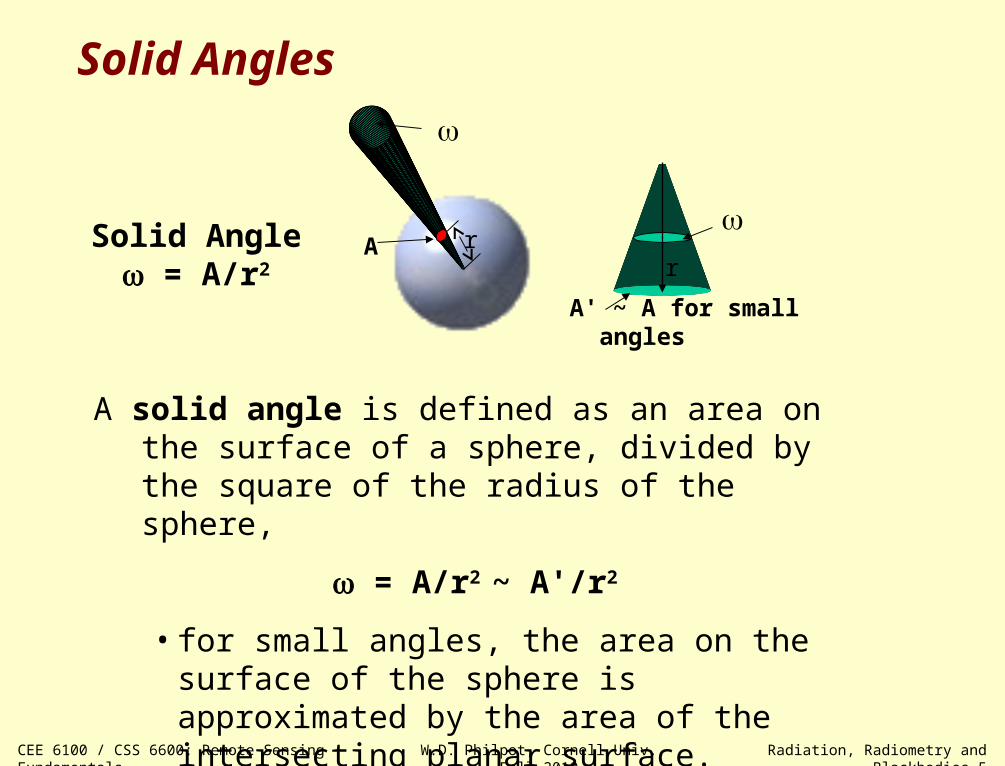
Solid Angles
A solid angle is defined as an area on the surface of a sphere, divided by the square of the radius of the sphere,
= A/r2 ~ A'/r2
• for small angles, the area on the surface of the sphere is approximated by the area of the intersecting planar surface.
rA
A' ~ A for small angles
Solid Angle = A/r2 r
CEE 6100 / CSS 6600: Remote Sensing Fundamentals W.D. Philpot, Cornell Univ. Fall 2010 Radiation, Radiometry and Blackbodies 6
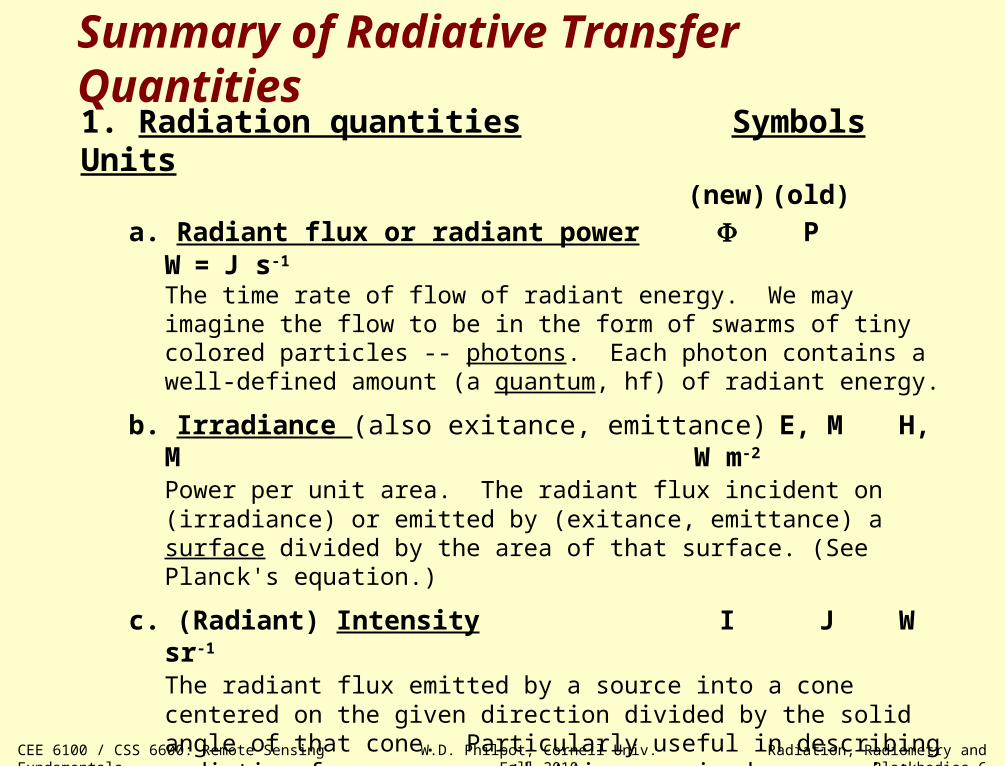
Summary of Radiative Transfer Quantities1. Radiation quantities Symbols Units
(new) (old)
a. Radiant flux or radiant power PW=J s-1
The time rate of flow of radiant energy. We may imagine the flow to be in the form of swarms of tiny colored particles -- photons. Each photon contains a well-defined amount (a quantum, hf) of radiant energy.
b. Irradiance (also exitance, emittance) E, M H, M W m-2
Power per unit area. The radiant flux incident on (irradiance) or emitted by (exitance, emittance) a surface divided by the area of that surface. (See Planck's equation.)
c. (Radiant) Intensity I J W sr-1
The radiant flux emitted by a source into a cone centered on the given direction divided by the solid angle of that cone. Particularly useful in describing radiation from a source that is perceived as a point source.
d. Radiance L N W m-2 sr-1
Radiant flux per unit solid angle per unit projected area. If a source is perceived/measured as an extended source, radiated power is described by radiance, L.
CEE 6100 / CSS 6600: Remote Sensing Fundamentals W.D. Philpot, Cornell Univ. Fall 2010 Radiation, Radiometry and Blackbodies 7
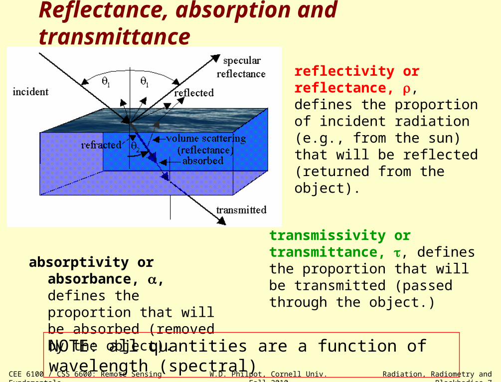
reflectivity or reflectance, , defines the proportion of incident radiation (e.g., from the sun) that will be reflected (returned from the object).
absorptivity or absorbance, , defines the proportion that will be absorbed (removed by the object).
transmissivity or transmittance, , defines the proportion that will be transmitted (passed through the object.)
NOTE: all quantities are a function of wavelength (spectral)
Reflectance, absorption and transmittance
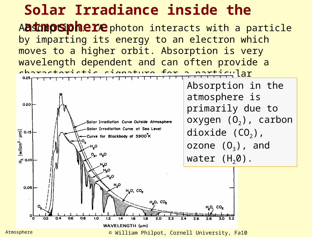
Solar Irradiance inside the atmosphereAbsorption. A photon interacts with a particle by imparting its energy to an electron which moves to a higher orbit. Absorption is very wavelength dependent and can often provide a characteristic signature for a particular substance.
Absorption in the atmosphere is primarily due to oxygen (O2), carbon dioxide (CO2), ozone (O3), and water (H20).
Atmosphere © William Philpot, Cornell University, Fa10
8

L* = Path radiance Lsat = v Lt + L*
Lsat = v [(sunEsuncos sun Esky)] Rrs(v) + L*
RT Model: Path Radiance
vvrs v
d
L( )R ( )
E
earth's surfaceEsky
L*
M
A
Atmosphere © William Philpot, Cornell University, Fa10
9
Esun
sunEsuncos sun
sun

10 CEE 610: RS Fundamentals – Frame Cameras
H
As
FOV
θFOV
FOV @ aperture = 2 H tan(θFOV)
The frame camera as radiometer
source element
[w m-2 sr -1]
Radiance at the aperture
as a a s
P PL
A A
s
s = IFOV = As / H2 sec3 = angle subtended by a source element at a distance R seca
a =Aa / H2 sec3 = angle subtended by a camera aperture at a distance R sec

11 CEE 610: RS Fundamentals – Frame Cameras
emulsion
anti-halationcoating
base
film,glass, or
paper
Photographic materials Solid State Detectors
• emulsion: most commonly a silver halide in a gelatin base
• base: paper, film, or glass
• anti-halation coating: an absorbing layer to suppress "halos" -- the spreading of a photographic image beyond its proper boundaries. Halation is caused primarily
• Each photodiode collects light independently
• The active area is smaller than the photodiode area
http://home.sandiego.edu/~ekim/photodiode/pdtech.html

12 CEE 610: RS Fundamentals – Frame Cameras
Characteristic (D log E) curve Response function
• Each film has a unique D log E curve
• The shape of the curve varies with conditions of development
• A film's sensitivity is determined from the film's characteristic curve.
• "Gross fog" = film base density + net fog (dark current for film)
Solid state analogs: characteristic curve response functionDmin dark currentDmax saturation
The gain of a photodiode under reverse bias is extremely linear with irradiance (illuminance) over a very wide dynamic range.
Photographic materials Solid State Detectors
gross fog
log E (Exposure)
Den
sity
(D
)
linearresponse
range
Dmax
Dmin
(dar
ken
ing
on t
he
neg
ativ
e)
101
logdensitytransmission

13
Photographic materials Solid State Silicon Detectors
• Both are frame cameras, i.e., they image the entire 2-D array at one time.
• The fundamental optics are identical, both in terms of advantages and limitations.
• The spectral range of sensitivity is from the near UV through the NIR
• Film is a random medium – there is no orientation associated with the response
• Digital arrays are arranged in a rectangular grid.
• There are no gaps in film between detection elements.
• The detection surface is discontinuous.
• For a given speed and aperture setting, film products are limited to roughly 8-bits of information (distinct gray levels).
• Digital arrays (professional cameras) commonly capture up to12-bits of (reproducible) information
• The spectral range and specificity of film can range from near UV through the NIR
• The spectral range of solid state detectors (other than silicon based) can be extended into the SWIR, MIR and TIR
• Color film provides full resolution for all three channels
• Single array cameras generally use separate color filters over individual detector elements (e.g,. the Bayer Pattern) to produce color imagery.

© W. Philpot, Cornell University, Fall-09 CEE 6100: Remote Sensing Fundamentals 14
Digital Cameras have only one 2-D array which is essentially a grayscale device.
A Color Filter Array (CFA) is placed between the lens and the sensors. A CFA typically has one color filter element for each sensor.
Bayer Pattern
The Bayer pattern uses the three additive primary colors, red, green and blue (RGB), for the filter elements. Since there are two Green elements in every set of 4 elements, this is sometimes referred to as an RGBG mask. The extra Green is used to create contrast in the image.

0.00
0.02
0.04
0.06
0.08
0.10
0.12
0.14
0.16
0.18
0.20
400 700 1000 1300 1600 1900 2200 2500
Refle
ctan
ce
wavelength (nm)
Laboratory ReflectancePaving Asphalt
Const. Asphalt
Galv. Steel 1
Galv. Steel 2
Bare Soil
vegetation

W. Philpot, Fa 10 CEE 6100 / CSS 6600: Photogrammetry 16
Photogrammetry
Photogrammetry:
Making precise measurements from images
• Close range photogrammetry: with camera focus set to a finite value.
• Far range photogrammetry: with camera focus setting to indefinite (infinity)

W. Philpot, Fa 10 CEE 6100 / CSS 6600: Photogrammetry 17
Depth of field
http://www.cs.mtu.edu/~shene/DigiCam/User-Guide/950/depth-of-field.html
• A lens focused on the yellow dot generates a yellow dot on the image plane. The yellow dot and all objects having the same subject-lens distance will appear sharp.
• The white dot, with larger subject-lens distance, will be out of focus. Its image is actually formed somewhere in front of the image plane and the image of this white dot on the image plane is a circle (the circle of confusion). As the subject-lens distance increases, the size of this circle increases.
• The same holds true for a subject in front of the yellow dot (e.g., the green dot).
• The size of a circle of confusion is proportional to the amount of light that can pass through the lens tube. Thus, smaller circles of confusion will be formed if less light can pass through. Therefore, a smaller aperture means smaller circles of confusion and a sharper image.
aperture

W. Philpot, Fa 10 CEE 6100 / CSS 6600: Photogrammetry 18
Basic Optics: thin lens equation
o i
imag
e
f
obje
ct
1 1 1
o i f
i h ' image sizeM
o h object size
thin lens equation:
magnification:
h
h'
depth of field
optic axis

W. Philpot, Fa 10 CEE 6100 / CSS 6600: Photogrammetry 19
Long range photogrammetry: focus at infinity
1 1 1
o if
f
h 'M Scale
o h
f
thin lens equation:
magnification:
i ≈ fo
W. Philpot, Fa 10 CEE 6100 / CSS 6600: Photogrammetry 20
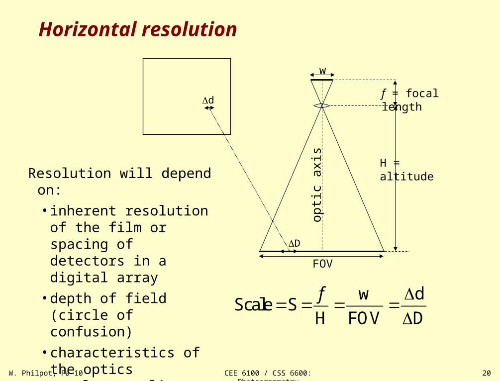
Horizontal resolution
w dScale S
H FOV D
f
H = altitude
opti
c ax
is
FOV
w
d
D
f = focal length
Resolution will depend on:
• inherent resolution of the film or spacing of detectors in a digital array
• depth of field (circle of confusion)
• characteristics of the optics– lens quality – focal length– imaging geometry
W. Philpot, Fa 10 CEE 6100 / CSS 6600: Photogrammetry 21
fa
a'bt
rb'rb
ra'ra
da
RARB
A
A'
H
hT
hB hA
• •
• •
•• • •
datum ground
photo
nadir point
•
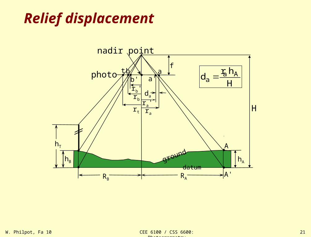
Relief displacement
a Aa
r hd
H•b'
rt
W. Philpot, Fa 10CEE 6100 / CSS 6600: Photogrammetry 22
f
H-h
dp1
o2o1
x1
h
H
dp2
o2o1
x2
imageplane
rearnode(lens)
O1 O2
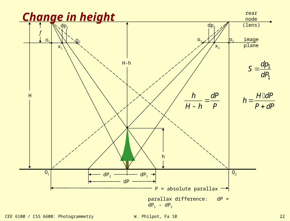
dP
P = absolute parallax
dP1dP2
parallax difference: dP = dP1 – dP2
h dP
H h P
H dP
hP dP
Change in height
1
1
dpS
dP
W. Philpot, Fa 10 CEE 6100 / CSS 6600: Photogrammetry 23
perspective center
t
ff
d'
d d''
n'
n
Pa a''
a'equivalent vertical photo
•
•
•
••• •
i
tilted photo•
AB
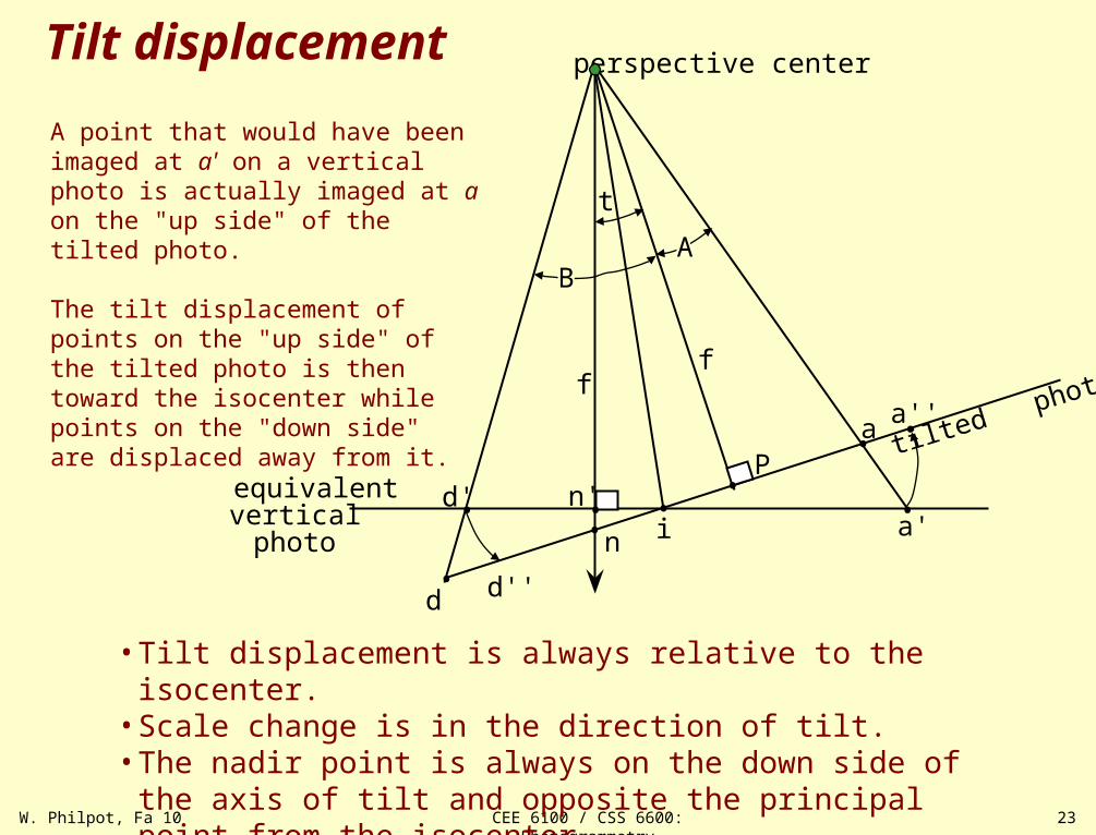
• Tilt displacement is always relative to the isocenter.• Scale change is in the direction of tilt.• The nadir point is always on the down side of the axis of tilt and
opposite the principal point from the isocenter
Tilt displacement
A point that would have been imaged at a' on a vertical photo is actually imaged at a on the "up side" of the tilted photo.
The tilt displacement of points on the "up side" of the tilted photo is then toward the isocenter while points on the "down side" are displaced away from it.
•

W. Philpot, Fa 10 CEE 6100 / CSS 6600: Photogrammetry 24
Flight Planning
Factors to consider:
1. General issues• focal length• film size (format)• photo scale / FOV• overlap / sidelap (continuous coverage, stereo, …)
2. Issues specific to the application• spectral considerations (film / filter) • time of day (illumination, sun orientation, tidal stage, …)• season (crop calendar, leaf on, leaf off, …)• sun orientation, sun angle
W. Philpot, Fa 10 CEE 6100 / CSS 6600: Photogrammetry 25
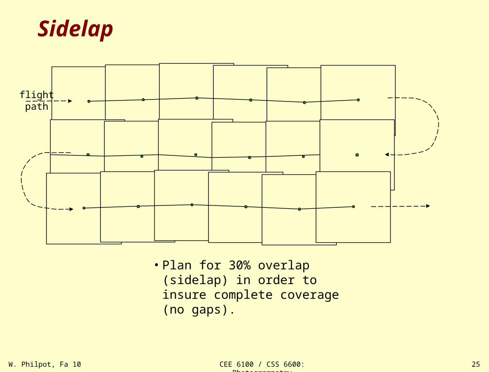
Sidelap
flightpath
• Plan for 30% overlap (sidelap) in order to insure complete coverage (no gaps).