ce371– structural analysis ii lecture 4: 14.1 - kunetammar.kunet.com/notes/ce371/lecture-4.pdf ·...
TRANSCRIPT

CE371– Structural Analysis II Lecture 4: 14.1 – 14.7 14.1) Fundamentals of the Stiffness Method 14.2) Member Stiffness Matrix 14.3) Displacement & Force Transformation Matrices 14.4) Member Global Stiffness Matrix 14.5) Truss Stiffness Matrix 14.6) Application of Stiffness Method for Trusses 14.7) Nodal Coordinates
CE371 – Structural Analysis II Dr. Ammar T. Al-Sayegh

14.1) Fundamentals of the Stiffness Method The Stiffness Method (SM) is a displacement method of
analysis (as opposed to the Flexibility Method which is a force method of analysis).
SM can be used to analyze both statically determinate and indeterminate structures by yielding the displacements of the analyzed structure.
SM uses matrices which are easy to formulate in computers. Thus, SM is usually the method of choice for solving structural problems using computers.
Application of SM requires subdividing the structure into a series of finite elements and identify their end points as nodes. These finite elements can be truss members, beam-column members, or any other structural member.
CE371 – Structural Analysis II Dr. Ammar T. Al-Sayegh 1
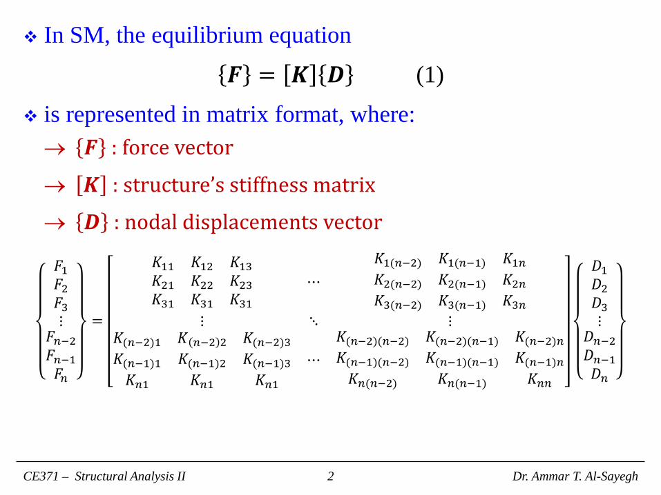
In SM, the equilibrium equation
𝑭𝑭 = 𝑲𝑲 𝑫𝑫 (1)
is represented in matrix format, where: → 𝑭𝑭 : force vector
→ 𝑲𝑲 : structure’s stiffness matrix
→ 𝑫𝑫 : nodal displacements vector
𝐹𝐹1𝐹𝐹2𝐹𝐹3⋮
𝐹𝐹𝑛𝑛−2𝐹𝐹𝑛𝑛−1𝐹𝐹𝑛𝑛
=
𝐾𝐾11 𝐾𝐾12 𝐾𝐾13𝐾𝐾21 𝐾𝐾22 𝐾𝐾23𝐾𝐾31 𝐾𝐾31 𝐾𝐾31
⋯𝐾𝐾1(𝑛𝑛−2) 𝐾𝐾1(𝑛𝑛−1) 𝐾𝐾1𝑛𝑛𝐾𝐾2(𝑛𝑛−2) 𝐾𝐾2(𝑛𝑛−1) 𝐾𝐾2𝑛𝑛𝐾𝐾3(𝑛𝑛−2) 𝐾𝐾3(𝑛𝑛−1) 𝐾𝐾3𝑛𝑛
⋮ ⋱ ⋮𝐾𝐾(𝑛𝑛−2)1 𝐾𝐾 𝑛𝑛−2 2 𝐾𝐾(𝑛𝑛−2)3𝐾𝐾(𝑛𝑛−1)1 𝐾𝐾(𝑛𝑛−1)2 𝐾𝐾(𝑛𝑛−1)3𝐾𝐾𝑛𝑛1 𝐾𝐾𝑛𝑛1 𝐾𝐾𝑛𝑛1
⋯𝐾𝐾(𝑛𝑛−2)(𝑛𝑛−2) 𝐾𝐾(𝑛𝑛−2)(𝑛𝑛−1) 𝐾𝐾(𝑛𝑛−2)𝑛𝑛𝐾𝐾(𝑛𝑛−1)(𝑛𝑛−2) 𝐾𝐾(𝑛𝑛−1)(𝑛𝑛−1) 𝐾𝐾(𝑛𝑛−1)𝑛𝑛𝐾𝐾𝑛𝑛(𝑛𝑛−2) 𝐾𝐾𝑛𝑛(𝑛𝑛−1) 𝐾𝐾𝑛𝑛𝑛𝑛
𝐷𝐷1𝐷𝐷2𝐷𝐷3⋮
𝐷𝐷𝑛𝑛−2𝐷𝐷𝑛𝑛−1𝐷𝐷𝑛𝑛
CE371 – Structural Analysis II Dr. Ammar T. Al-Sayegh 2

Truss Node and Member Identification: Node Number: Each joint in a truss will be identified with a node
number, which is the circled number near each joint.
Member Number: Each member in a truss will be identified with a member number, which is the squared number on each member.
Near and Far Ends of a Member: An arrow is used to identify the near and far nodes of a member.
CE371 – Structural Analysis II Dr. Ammar T. Al-Sayegh 3

Global and Local Coordinates: Global Coordinates: coordinate system (x, y) that can locate
any joint in the structure according to a single reference point relative to the structure.
Local Coordinates: coordinate system (x’, y’) that can locate any point on the element according to a single reference point on the element. For convenience, let near end be the origin, x’ goes toward far end, y’ goes perpendicular to x’.
CE371 – Structural Analysis II Dr. Ammar T. Al-Sayegh 4
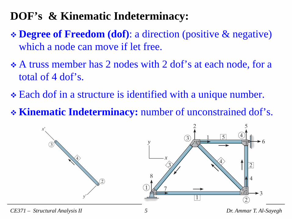
DOF’s & Kinematic Indeterminacy: Degree of Freedom (dof): a direction (positive & negative)
which a node can move if let free.
A truss member has 2 nodes with 2 dof’s at each node, for a total of 4 dof’s.
Each dof in a structure is identified with a unique number.
Kinematic Indeterminacy: number of unconstrained dof’s.
CE371 – Structural Analysis II Dr. Ammar T. Al-Sayegh 5
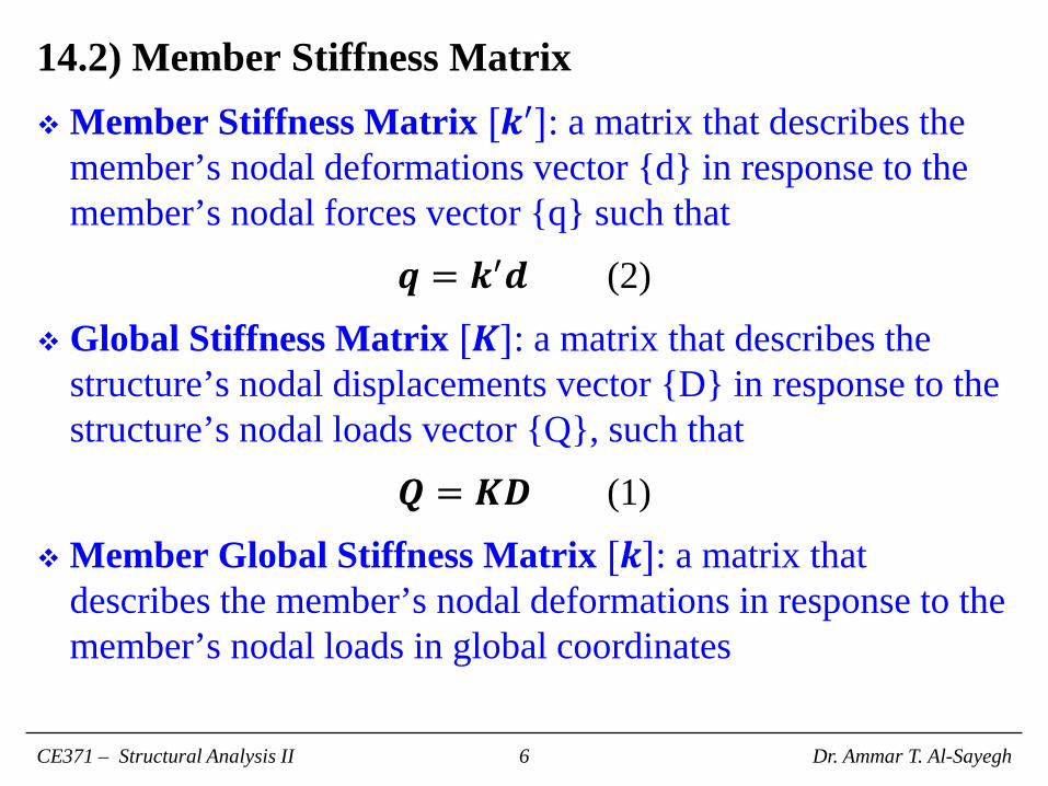
14.2) Member Stiffness Matrix Member Stiffness Matrix [𝒌𝒌′]: a matrix that describes the
member’s nodal deformations vector {d} in response to the member’s nodal forces vector {q} such that
𝒒𝒒 = 𝒌𝒌′𝒅𝒅 (2)
Global Stiffness Matrix [𝑲𝑲]: a matrix that describes the structure’s nodal displacements vector {D} in response to the structure’s nodal loads vector {Q}, such that
𝑸𝑸 = 𝑲𝑲𝑫𝑫 (1)
Member Global Stiffness Matrix [𝒌𝒌]: a matrix that describes the member’s nodal deformations in response to the member’s nodal loads in global coordinates
CE371 – Structural Analysis II Dr. Ammar T. Al-Sayegh 6
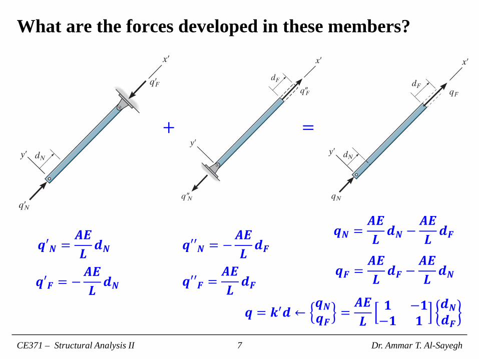
What are the forces developed in these members?
CE371 – Structural Analysis II Dr. Ammar T. Al-Sayegh 7
𝒒𝒒𝒒𝑵𝑵 =𝑨𝑨𝑨𝑨𝑳𝑳𝒅𝒅𝑵𝑵
𝒒𝒒𝒒𝑭𝑭 = −𝑨𝑨𝑨𝑨𝑳𝑳𝒅𝒅𝑵𝑵
𝒒𝒒𝒒𝒒𝑵𝑵 = −𝑨𝑨𝑨𝑨𝑳𝑳𝒅𝒅𝑭𝑭
𝒒𝒒𝒒𝒒𝑭𝑭 =𝑨𝑨𝑨𝑨𝑳𝑳𝒅𝒅𝑭𝑭
+ =
𝒒𝒒𝑵𝑵 =𝑨𝑨𝑨𝑨𝑳𝑳𝒅𝒅𝑵𝑵 −
𝑨𝑨𝑨𝑨𝑳𝑳𝒅𝒅𝑭𝑭
𝒒𝒒𝑭𝑭 =𝑨𝑨𝑨𝑨𝑳𝑳𝒅𝒅𝑭𝑭 −
𝑨𝑨𝑨𝑨𝑳𝑳𝒅𝒅𝑵𝑵
𝒒𝒒 = 𝒌𝒌′𝒅𝒅 ←𝒒𝒒𝑵𝑵𝒒𝒒𝑭𝑭 =
𝑨𝑨𝑨𝑨𝑳𝑳
𝟏𝟏 −𝟏𝟏−𝟏𝟏 𝟏𝟏
𝒅𝒅𝑵𝑵𝒅𝒅𝑭𝑭
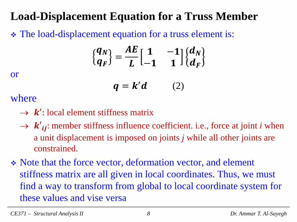
Load-Displacement Equation for a Truss Member The load-displacement equation for a truss element is:
𝒒𝒒𝑵𝑵𝒒𝒒𝑭𝑭 =
𝑨𝑨𝑨𝑨𝑳𝑳
𝟏𝟏 −𝟏𝟏−𝟏𝟏 𝟏𝟏
𝒅𝒅𝑵𝑵𝒅𝒅𝑭𝑭
or 𝒒𝒒 = 𝒌𝒌′𝒅𝒅 (2)
where → 𝒌𝒌′: local element stiffness matrix → 𝒌𝒌𝒒𝒊𝒊𝒊𝒊: member stiffness influence coefficient. i.e., force at joint i when
a unit displacement is imposed on joints j while all other joints are constrained.
Note that the force vector, deformation vector, and element stiffness matrix are all given in local coordinates. Thus, we must find a way to transform from global to local coordinate system for these values and vise versa
CE371 – Structural Analysis II Dr. Ammar T. Al-Sayegh 8

14.3) Displacement & Force Transformation Matrices Consider the following truss, and let:
CE371 – Structural Analysis II Dr. Ammar T. Al-Sayegh 9
→ 𝒙𝒙,𝒚𝒚: global axes.
→ 𝒙𝒙𝒒, 𝒚𝒚𝒒: local axes.
→ 𝜽𝜽𝒙𝒙: smallest angle between local and global x-axes.
→ 𝜽𝜽𝒚𝒚: smallest angle between local and global y-axes.
→ λx = 𝒄𝒄𝒄𝒄𝒄𝒄(𝜽𝜽𝒙𝒙) = 𝑥𝑥𝐹𝐹−𝑥𝑥𝑁𝑁𝐿𝐿
= 𝑥𝑥𝐹𝐹−𝑥𝑥𝑁𝑁
(𝑥𝑥𝐹𝐹−𝑥𝑥𝑁𝑁)2+2(𝑦𝑦𝐹𝐹−𝑦𝑦𝑁𝑁)2
→ λy = 𝒄𝒄𝒄𝒄𝒄𝒄(𝜽𝜽𝒚𝒚) = 𝑦𝑦𝐹𝐹−𝑦𝑦𝑁𝑁𝐿𝐿
= 𝑦𝑦𝐹𝐹−𝑦𝑦𝑁𝑁
(𝑥𝑥𝐹𝐹−𝑥𝑥𝑁𝑁)2+2(𝑦𝑦𝐹𝐹−𝑦𝑦𝑁𝑁)2
Effects of global displacement D on local deformation d.
𝒅𝒅𝑵𝑵 = 𝑫𝑫𝑵𝑵𝒙𝒙𝒄𝒄𝒄𝒄𝒄𝒄𝜽𝜽𝒙𝒙 + 𝑫𝑫𝑵𝑵𝒚𝒚𝒄𝒄𝒄𝒄𝒄𝒄𝜽𝜽𝒚𝒚
𝒅𝒅𝑭𝑭 = 𝑫𝑫𝑭𝑭𝒙𝒙𝒄𝒄𝒄𝒄𝒄𝒄𝜽𝜽𝒙𝒙 + 𝑫𝑫𝑭𝑭𝒚𝒚𝒄𝒄𝒄𝒄𝒄𝒄𝜽𝜽𝒚𝒚

The two equations: 𝒅𝒅𝑵𝑵 = 𝑫𝑫𝑵𝑵𝒙𝒙𝒄𝒄𝒄𝒄𝒄𝒄𝜽𝜽𝒙𝒙 + 𝑫𝑫𝑵𝑵𝒚𝒚𝒄𝒄𝒄𝒄𝒄𝒄𝜽𝜽𝒚𝒚𝒅𝒅𝑭𝑭 = 𝑫𝑫𝑭𝑭𝒙𝒙𝒄𝒄𝒄𝒄𝒄𝒄𝜽𝜽𝒙𝒙 + 𝑫𝑫𝑭𝑭𝒚𝒚𝒄𝒄𝒄𝒄𝒄𝒄𝜽𝜽𝒚𝒚
can be rewritten in matrix format:
𝒅𝒅𝑵𝑵𝒅𝒅𝑭𝑭
=𝞴𝞴𝒙𝒙 𝞴𝞴𝒚𝒚 𝟎𝟎 𝟎𝟎𝟎𝟎 𝟎𝟎 𝞴𝞴𝒙𝒙 𝞴𝞴𝒚𝒚
𝑫𝑫𝑵𝑵𝒙𝒙𝑫𝑫𝑵𝑵𝒚𝒚𝑫𝑫𝑭𝑭𝒙𝒙𝑫𝑫𝑭𝑭𝒚𝒚
or
𝒅𝒅 = 𝑻𝑻𝑫𝑫 where
𝑻𝑻 =𝞴𝞴𝒙𝒙 𝞴𝞴𝒚𝒚 𝟎𝟎 𝟎𝟎𝟎𝟎 𝟎𝟎 𝞴𝞴𝒙𝒙 𝞴𝞴𝒚𝒚
CE371 – Structural Analysis II Dr. Ammar T. Al-Sayegh 10

Consider once again the following truss:
CE371 – Structural Analysis II Dr. Ammar T. Al-Sayegh 11
Effects of local forces q on global forces Q.
𝑸𝑸𝑵𝑵𝒙𝒙 = 𝒒𝒒𝑵𝑵𝒄𝒄𝒄𝒄𝒄𝒄𝜽𝜽𝒙𝒙
𝑸𝑸𝑵𝑵𝒚𝒚 = 𝒒𝒒𝑵𝑵𝒄𝒄𝒄𝒄𝒄𝒄𝜽𝜽𝒚𝒚
𝑸𝑸𝑭𝑭𝒙𝒙 = 𝒒𝒒𝑵𝑵𝒄𝒄𝒄𝒄𝒄𝒄𝜽𝜽𝒙𝒙
𝑸𝑸𝑭𝑭𝒚𝒚 = 𝒒𝒒𝑭𝑭𝒄𝒄𝒄𝒄𝒄𝒄𝜽𝜽𝒚𝒚
So global and local forces are related as: 𝑸𝑸𝑵𝑵𝒙𝒙𝑸𝑸𝑵𝑵𝒚𝒚𝑸𝑸𝑭𝑭𝒙𝒙𝑸𝑸𝑭𝑭𝒙𝒙
=
𝞴𝞴𝒙𝒙 𝟎𝟎𝞴𝞴𝒚𝒚𝟎𝟎𝟎𝟎
𝟎𝟎𝞴𝞴𝒙𝒙𝞴𝞴𝒚𝒚
𝒒𝒒𝑵𝑵𝒒𝒒𝑵𝑵
or 𝐐𝐐 = 𝑻𝑻𝑻𝑻𝒒𝒒
where 𝑻𝑻𝑻𝑻transforms 2 end forces in local coordinates to 4 end forces in global coordinates.

14.4) Member Global Stiffness Matrix Getting back to Eq. (2), 𝒒𝒒 = 𝒌𝒌′𝒅𝒅, which compute end forces from
end displacements in local coordinates. It can be restated as 𝒒𝒒 = 𝒌𝒌′𝑻𝑻𝑫𝑫 (3)
Multiplying both sides of Eq. (3) by 𝑻𝑻𝑻𝑻 we get: 𝑸𝑸 = 𝑻𝑻𝑻𝑻𝒌𝒌′𝑻𝑻𝑫𝑫 (4)
Let 𝑻𝑻𝑻𝑻𝒌𝒌′𝑻𝑻 be the member stiffness in global coordinates. Then, 𝑸𝑸 = 𝒌𝒌𝑫𝑫 (5)
Calculating the element stiffness in global coordinates gives:
𝒌𝒌 =
𝞴𝞴𝒙𝒙 𝟎𝟎𝞴𝞴𝒚𝒚𝟎𝟎𝟎𝟎
𝟎𝟎𝞴𝞴𝒙𝒙𝞴𝞴𝒚𝒚
𝑨𝑨𝑨𝑨
𝑳𝑳
𝟏𝟏 −𝟏𝟏−𝟏𝟏 𝟏𝟏
𝞴𝞴𝒙𝒙 𝞴𝞴𝒚𝒚 𝟎𝟎 𝟎𝟎𝟎𝟎 𝟎𝟎 𝞴𝞴𝒙𝒙 𝞴𝞴𝒚𝒚
(6)
CE371 – Structural Analysis II Dr. Ammar T. Al-Sayegh 12
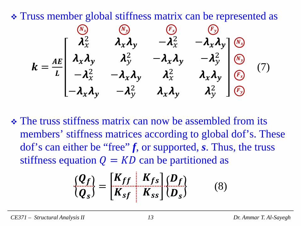
Truss member global stiffness matrix can be represented as
𝒌𝒌 = 𝑨𝑨𝑨𝑨𝑳𝑳
𝞴𝞴𝑥𝑥2 𝞴𝞴𝒙𝒙𝞴𝞴𝒚𝒚 −𝞴𝞴𝑥𝑥2 −𝞴𝞴𝒙𝒙𝞴𝞴𝒚𝒚𝞴𝞴𝒙𝒙𝞴𝞴𝒚𝒚 𝞴𝞴𝑦𝑦2 −𝞴𝞴𝒙𝒙𝞴𝞴𝒚𝒚 −𝞴𝞴𝑦𝑦2
−𝞴𝞴𝑥𝑥2 −𝞴𝞴𝒙𝒙𝞴𝞴𝒚𝒚 𝞴𝞴𝑥𝑥2 𝞴𝞴𝒙𝒙𝞴𝞴𝒚𝒚−𝞴𝞴𝒙𝒙𝞴𝞴𝒚𝒚 −𝞴𝞴𝑦𝑦2 𝞴𝞴𝒙𝒙𝞴𝞴𝒚𝒚 𝞴𝞴𝑦𝑦2
(7)
The truss stiffness matrix can now be assembled from its
members’ stiffness matrices according to global dof’s. These dof’s can either be “free” f, or supported, s. Thus, the truss stiffness equation 𝑄𝑄 = 𝐾𝐾𝐷𝐷 can be partitioned as
𝑸𝑸𝒇𝒇𝑸𝑸𝒄𝒄
=𝑲𝑲𝒇𝒇𝒇𝒇 𝑲𝑲𝒇𝒇𝒄𝒄𝑲𝑲𝒄𝒄𝒇𝒇 𝑲𝑲𝒄𝒄𝒄𝒄
𝑫𝑫𝒇𝒇𝑫𝑫𝒄𝒄
(8)
CE371 – Structural Analysis II Dr. Ammar T. Al-Sayegh 13
𝑵𝑵𝒙𝒙 𝑵𝑵𝒚𝒚 𝑭𝑭𝒙𝒙 𝑭𝑭𝒚𝒚
𝑵𝑵𝒙𝒙
𝑵𝑵𝒚𝒚
𝑭𝑭𝒙𝒙
𝑭𝑭𝒚𝒚

𝑸𝑸𝒇𝒇 represents known loads, because loads on free dof’s are either prescribed or zero such that 𝑸𝑸𝒇𝒇 = 𝑷𝑷, while 𝑸𝑸𝒄𝒄 is the known reactions vector, such that 𝑸𝑸𝒄𝒄 = 𝑹𝑹.
𝑫𝑫𝒇𝒇 represents the unknown displacements of the free dof’s, while 𝑫𝑫𝒄𝒄 are the known supported dof displacements which are either zero or have prescribed values.
It can be seen from Eq. (8) that 𝑸𝑸𝒇𝒇 = 𝑲𝑲𝒇𝒇𝒇𝒇 𝑫𝑫𝒇𝒇 + 𝑲𝑲𝒇𝒇𝒄𝒄 𝑫𝑫𝒄𝒄 (9) 𝑸𝑸𝒄𝒄 = 𝑲𝑲𝒄𝒄𝒇𝒇 𝑫𝑫𝒇𝒇 + 𝑲𝑲𝒄𝒄𝒄𝒄 𝑫𝑫𝒄𝒄 (10)
Multiplying Eq. (9) by 𝑲𝑲𝒇𝒇𝒇𝒇 −1 and rearranging 𝑫𝑫𝒇𝒇 = 𝑲𝑲𝒇𝒇𝒇𝒇 −1 𝑸𝑸𝒇𝒇 − 𝑲𝑲𝒇𝒇𝒄𝒄 𝑫𝑫𝒄𝒄 (11)
Using 𝑫𝑫𝒇𝒇 , 𝑸𝑸𝒄𝒄 can be calculated from Eq. (10).
CE371 – Structural Analysis II Dr. Ammar T. Al-Sayegh 14
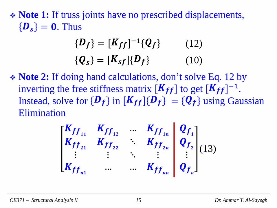
Note 1: If truss joints have no prescribed displacements, 𝑫𝑫𝒄𝒄 = 𝟎𝟎. Thus
𝑫𝑫𝒇𝒇 = 𝑲𝑲𝒇𝒇𝒇𝒇 −1 𝑸𝑸𝒇𝒇 (12) 𝑸𝑸𝒄𝒄 = 𝑲𝑲𝒄𝒄𝒇𝒇 𝑫𝑫𝒇𝒇 (10)
Note 2: If doing hand calculations, don’t solve Eq. 12 by inverting the free stiffness matrix 𝑲𝑲𝒇𝒇𝒇𝒇 to get 𝑲𝑲𝒇𝒇𝒇𝒇 −1. Instead, solve for 𝑫𝑫𝒇𝒇 in 𝑲𝑲𝒇𝒇𝒇𝒇 𝑫𝑫𝒇𝒇 = 𝑸𝑸𝒇𝒇 using Gaussian Elimination
𝑲𝑲𝒇𝒇𝒇𝒇𝟏𝟏𝟏𝟏 𝑲𝑲𝒇𝒇𝒇𝒇𝟏𝟏𝟐𝟐 … 𝑲𝑲𝒇𝒇𝒇𝒇𝟏𝟏𝒏𝒏 𝑸𝑸𝒇𝒇𝟏𝟏𝑲𝑲𝒇𝒇𝒇𝒇𝟐𝟐𝟏𝟏 𝑲𝑲𝒇𝒇𝒇𝒇𝟐𝟐𝟐𝟐 ⋱ 𝑲𝑲𝒇𝒇𝒇𝒇𝟐𝟐𝒏𝒏 𝑸𝑸𝒇𝒇𝟐𝟐⋮ ⋮ ⋱ ⋮ ⋮
𝑲𝑲𝒇𝒇𝒇𝒇𝒏𝒏𝟏𝟏 … … 𝑲𝑲𝒇𝒇𝒇𝒇𝒏𝒏𝒏𝒏 𝑸𝑸𝒇𝒇𝒏𝒏
(13)
CE371 – Structural Analysis II Dr. Ammar T. Al-Sayegh 15
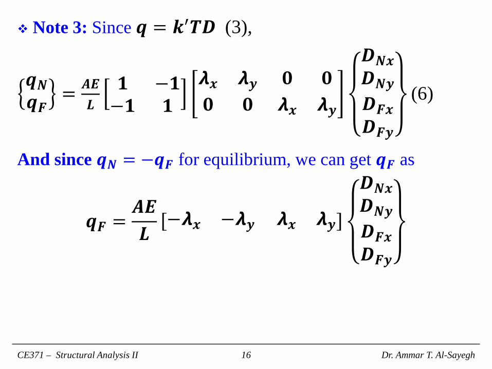
Note 3: Since 𝒒𝒒 = 𝒌𝒌′𝑻𝑻𝑫𝑫 (3),
𝒒𝒒𝑵𝑵𝒒𝒒𝑭𝑭 = 𝑨𝑨𝑨𝑨
𝑳𝑳𝟏𝟏 −𝟏𝟏−𝟏𝟏 𝟏𝟏
𝞴𝞴𝒙𝒙 𝞴𝞴𝒚𝒚 𝟎𝟎 𝟎𝟎𝟎𝟎 𝟎𝟎 𝞴𝞴𝒙𝒙 𝞴𝞴𝒚𝒚
𝑫𝑫𝑵𝑵𝒙𝒙𝑫𝑫𝑵𝑵𝒚𝒚𝑫𝑫𝑭𝑭𝒙𝒙𝑫𝑫𝑭𝑭𝒚𝒚
(6)
And since 𝒒𝒒𝑵𝑵 = −𝒒𝒒𝑭𝑭 for equilibrium, we can get 𝒒𝒒𝑭𝑭 as
𝒒𝒒𝑭𝑭 =𝑨𝑨𝑨𝑨𝑳𝑳
−𝞴𝞴𝒙𝒙 −𝞴𝞴𝒚𝒚 𝞴𝞴𝒙𝒙 𝞴𝞴𝒚𝒚
𝑫𝑫𝑵𝑵𝒙𝒙𝑫𝑫𝑵𝑵𝒚𝒚𝑫𝑫𝑭𝑭𝒙𝒙𝑫𝑫𝑭𝑭𝒚𝒚
CE371 – Structural Analysis II Dr. Ammar T. Al-Sayegh 16
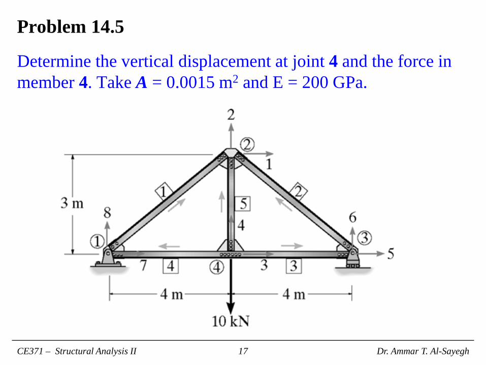
Problem 14.5
Determine the vertical displacement at joint 4 and the force in member 4. Take A = 0.0015 m2 and E = 200 GPa.
CE371 – Structural Analysis II Dr. Ammar T. Al-Sayegh 17
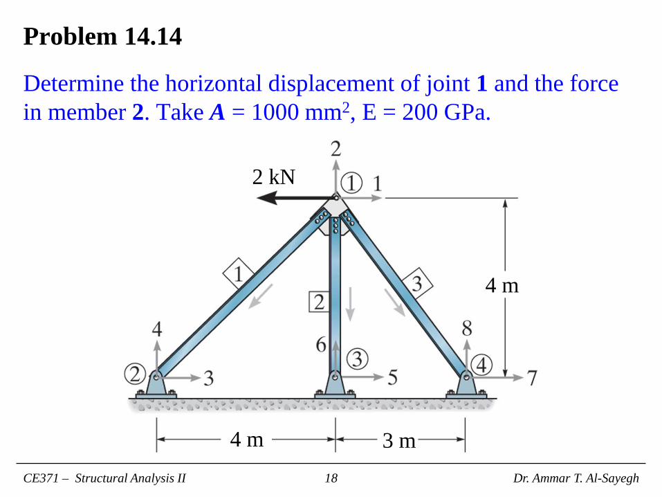
Problem 14.14
Determine the horizontal displacement of joint 1 and the force in member 2. Take A = 1000 mm2, E = 200 GPa.
CE371 – Structural Analysis II Dr. Ammar T. Al-Sayegh 18
2 kN
4 m
4 m 3 m
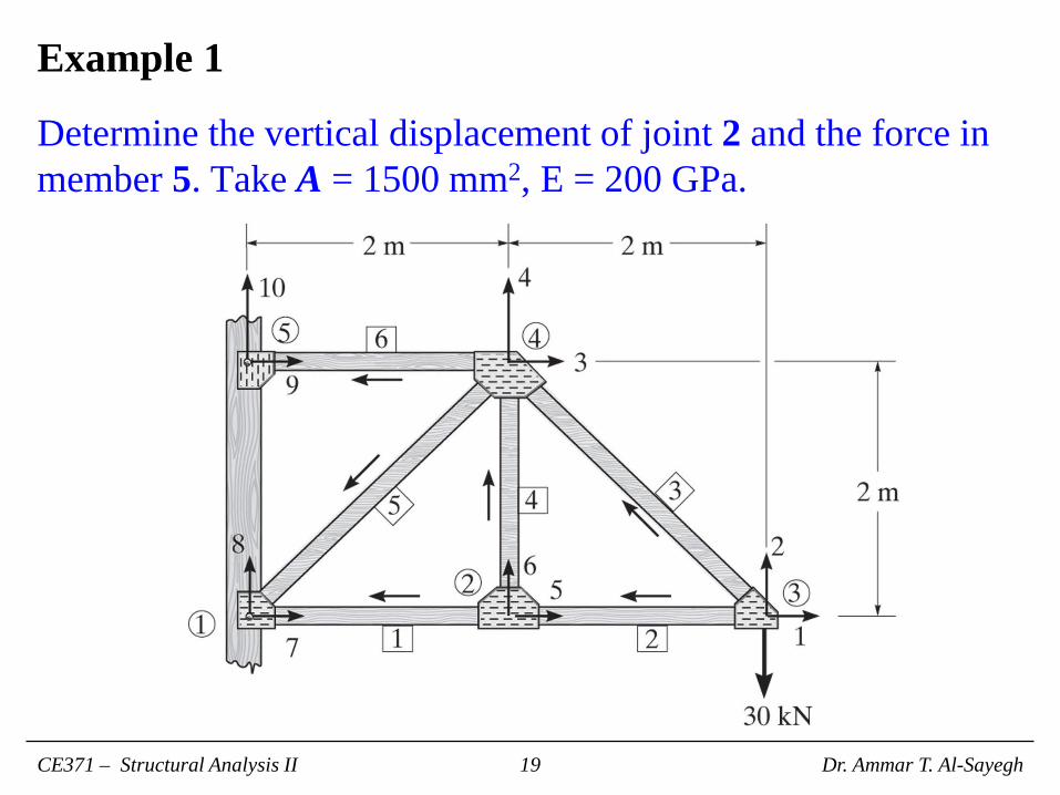
Example 1
Determine the vertical displacement of joint 2 and the force in member 5. Take A = 1500 mm2, E = 200 GPa.
CE371 – Structural Analysis II Dr. Ammar T. Al-Sayegh 19