ce-321: computer architecture
DESCRIPTION
Dr Mohamed Menacer College of Computer Science and Engineering Taibah University [email protected] www.mmenacer.info. Chapter 4: Input/Output. CE-321: Computer Architecture. Why peripherals are not connected directly to the system bus. Wide variety of peripherals - PowerPoint PPT PresentationTRANSCRIPT

Dr Mohamed MenacerCollege of Computer Science and EngineeringTaibah [email protected].
CE-321: Computer Architecture
Chapter 4: Input/Output
William Stallings, Computer Organization and Architecture, 8th Edition

Why peripherals are not connected directly to the system bus
• Wide variety of peripherals—Delivering different amounts of data—At different speeds—In different formats
• Data transfer rate of peripherals often much slower than CPU and RAM
• Some peripherals data transfer rate is faster than that of memory or processor.—Need I/O module

Input/Output Module
• Interface to processor and memory via the system bus or central switch
• Interface to one or more peripheral devices by data links.

Generic Model of I/O Module

External Devices
• Human readable—Screen, printer, keyboard
• Machine readable—Monitoring and control—Magnetic disk, tape systems, sensors and
actuators such as used in robotics application.• Communication
—Modem—Network Interface Card (NIC)

External Device Block Diagram

I/O Module Function
• Control & Timing• CPU Communication• Device Communication• Data Buffering• Error Detection

I/O Steps: the control of the transfer of datafrom an external device to processor involve:
• CPU checks I/O module device status• I/O module returns device status• If ready, CPU requests data transfer• I/O module gets data from device• I/O module transfers data to CPU• Variations for output, DMA, etc.

I/O Module Diagram

Input Output Techniques
• Programmed• Interrupt driven• Direct Memory Access (DMA)

Three Techniques for Input of a Block of Data

Programmed I/O
• CPU has direct control over I/O—Sensing status—Read/write commands—Transferring data
• CPU waits for I/O module to complete operation
• Wastes CPU time

I/O Commands
• CPU issues address—Identifies module (& device if >1 per module)
• CPU issues command—Control - telling module what to do
– e.g. spin up disk—Test - check status
– e.g. power? Error?—Read/Write
– Module transfers data via buffer from/to device

Addressing I/O Devices
• Under programmed I/O data transfer is very like memory access (CPU viewpoint)
• Each device given unique identifier• CPU commands contain identifier
(address)

I/O Mapping• Memory mapped I/O
—Devices and memory share an address space— I/O looks just like memory read/write—No special commands for I/O
– Large selection of memory access commands available
• Isolated I/O—Separate address spaces—Need I/O or memory select lines—Special commands for I/O
– Limited set

Interrupt Driven I/O
• Overcomes CPU waiting• No repeated CPU checking of device• I/O module interrupts when ready

Interrupt Driven I/OBasic Operation
• CPU issues read command• I/O module gets data from peripheral
whilst CPU does other work• I/O module interrupts CPU• CPU requests data• I/O module transfers data

Simple InterruptProcessing

Changes in Memory and Registersfor an Interrupt

Design Issues
• How do you identify the module issuing the interrupt?
• How do you deal with multiple interrupts?—i.e. an interrupt handler being interrupted

Identifying Interrupting Module (1)
• Different line for each module—PC—Limits number of devices
• Software poll—CPU asks each module in turn—Slow

Multiple Interrupts
• Each interrupt line has a priority• Higher priority lines can interrupt lower
priority lines• If bus mastering only current master can
interrupt

Example - PC Bus
• 80x86 has one interrupt line• 8086 based systems use one 8259A
interrupt controller• 8259A has 8 interrupt lines

Sequence of Events
• 8259A accepts interrupts• 8259A determines priority• 8259A signals 8086 (raises INTR line)• CPU Acknowledges• 8259A puts correct vector on data bus• CPU processes interrupt

ISA Bus Interrupt System
• ISA bus chains two 8259As together• Link is via interrupt 2• Gives 15 lines
—16 lines less one for link• IRQ 9 is used to re-route anything trying to
use IRQ 2—Backwards compatibility
• Incorporated in chip set
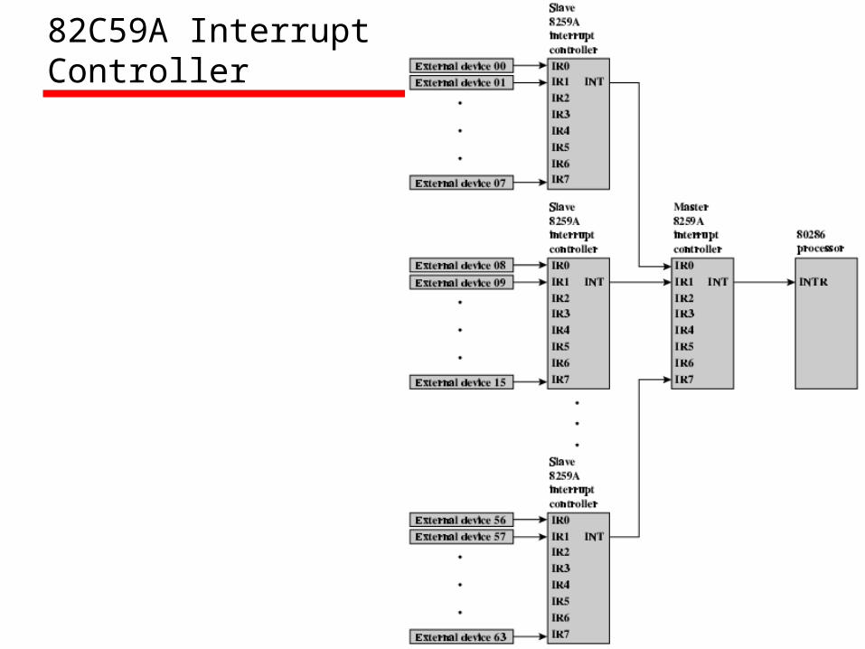
82C59A InterruptController

Intel 82C55A Programmable Peripheral Interface

Keyboard/Display Interfaces to 82C55A

Direct Memory Access
• Interrupt driven and programmed I/O require active CPU intervention—Transfer rate is limited—CPU is tied up
• DMA is the answer

DMA Function
• Additional Module (hardware) on bus• DMA controller takes over from CPU for I/O
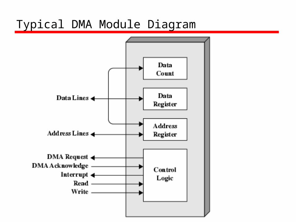
Typical DMA Module Diagram

DMA Operation
• CPU tells DMA controller:-—Read/Write—Device address—Starting address of memory block for data—Amount of data to be transferred
• CPU carries on with other work• DMA controller deals with transfer• DMA controller sends interrupt when
finished

DMA and Interrupt Breakpoints During an Instruction Cycle

8237 DMA Usage of Systems Bus

DMA Configurations (1)
• Single Bus, Detached DMA controller• Each transfer uses bus twice
—I/O to DMA then DMA to memory• CPU is suspended twice

DMA Configurations (2)
• Single Bus, Integrated DMA controller• Controller may support >1 device• Each transfer uses bus once
—DMA to memory• CPU is suspended once
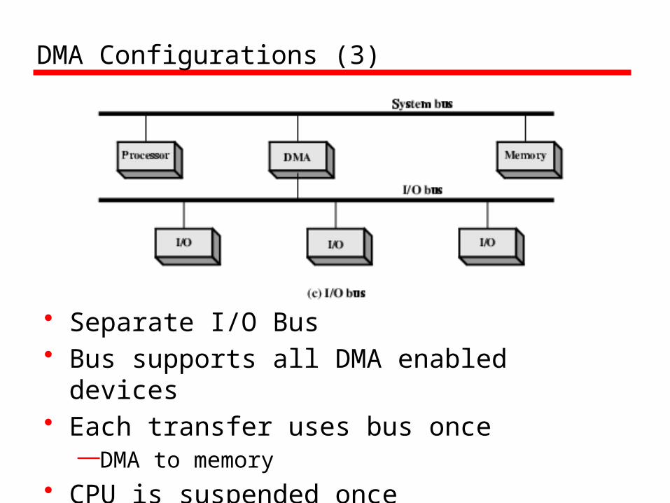
DMA Configurations (3)
• Separate I/O Bus• Bus supports all DMA enabled devices• Each transfer uses bus once
—DMA to memory• CPU is suspended once

Internet Resources- Web site for book• William Stallings
—Chapter 7
• http://WilliamStallings.com/COA/COA7e.html— links to sites of interest— links to sites for courses that use the book— information on other books by W. Stallings
• www.pcguide.com• http: www.howstuffworks.com• http: www.wikipedia.com